

Toshiba RAS-B13U2FVG-TR, RAS-B18U2FVG-TR, RAS-B18U2FVG-E, RAS-25U2FVG-ND, RAS-25U2AVPG-ND Service Manual
...
SERVICE MANUAL
SPLIT TYPE
Indoor Unit
<Console
, Heat Pump Type>
RAS-B10
U2FVG-E,-TR
RAS-B13
U2FVG-E,-TR
RAS-B18
U2FVG-E,-TR
May, 2018
R32
FILE NO. SVM-18048

CONTENTS
1. SAFETY PRECAUTIONS .......................................................................... 3
2. SPECIFICATIONS ..................................................................................... 7
3. REFRIGERANT R410A ............................................................................. 9
4. CONSTRUCTION VIEWS ........................................................................ 17
5. WIRING DIAGRAM .................................................................................. 18
6. SPECIFICATIONS OF ELECTRICAL PARTS ......................................... 19
7. REFRIGERANT CYCLE DIAGRAM ........................................................ 20
8. CONTROL BLOCK DIAGRAM ................................................................ 22
9. OPERATION DESCRIPTION................................................................... 23
10.
INSTALLATION PROCEDURE ................................................................ 57
11.
HOW TO DIAGNOSE THE TROUBLE...................................................... 65
12.
HOW TO REPLACE THE MAIN PARTS................................................... 88
13.
EXPLODED VIEWS AND PARTS LIST ................................................... 95
FILE NO. SVM-18048
- 2 -
1. SAFETY PRECAUTIONS
FILE NO. SVM-18048
- 3 -
SAFETY PRECAUTIONS
The important contents concerned to the safety are described on the product itself and on this Service Manual.
Please read this Service Manual after understanding the described items thoroughly in the following contents
(Indications/Illustrated marks), and keep them.
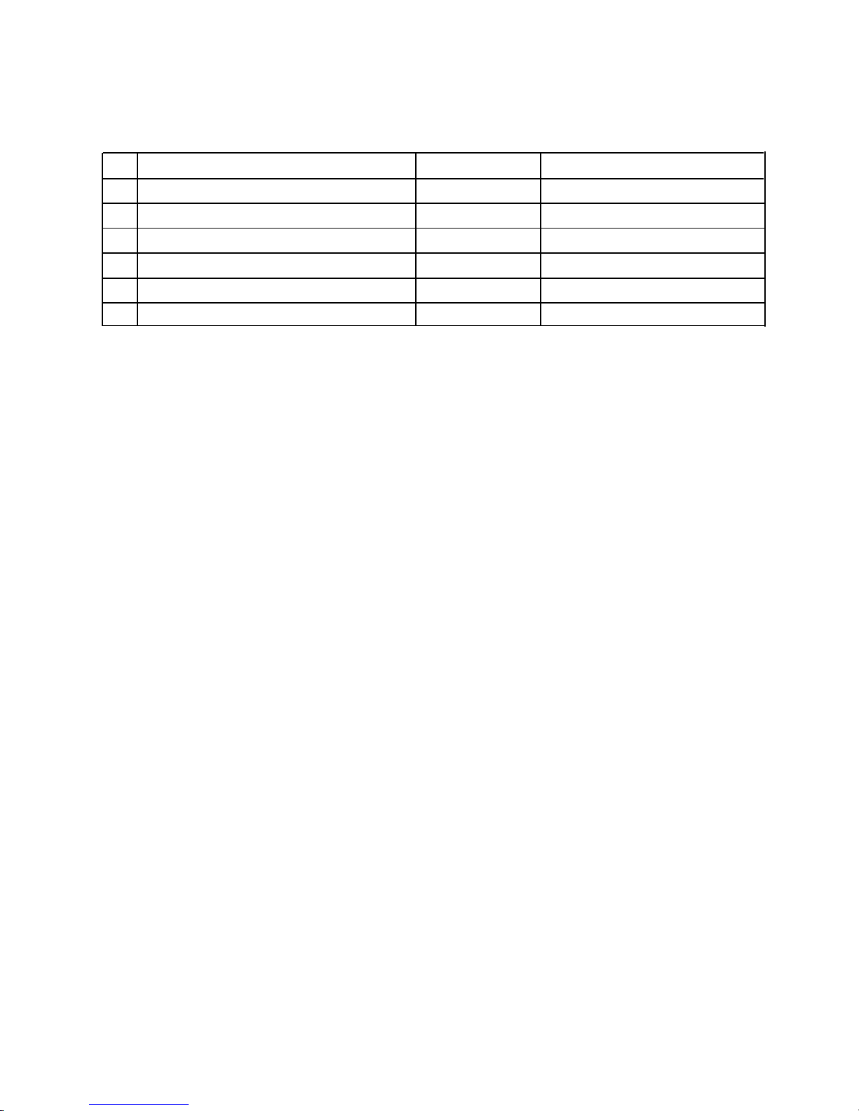
[Explanation of indications]
Indication Explanation
DANGER
WARNING
CAUTION
* Property damage : Enlarged damage concerned to property, furniture, and domestic animal/pet
Indicates contents assumed that an imminent danger causing a death or serious injury of the
repair engineers and the third parties when an incorrect work has been executed.
Indicates possibilities assumed that a danger causing a death or serious injury of the repair
engineers, the third parties, and the users due to troubles of the product after work when an
incorrect work has been executed.
Indicates contents assumed that an injury or property damage (*) may be caused on the repair
engineers, the third parties, and the users due to troubles of the product after work when an
incorrect work has been executed.
[Explanation of illustrated marks]
Mark Explanation
Indicates prohibited items (Forbidden items to do)
The sentences near an illustrated mark describe the concrete prohibited contents.
Indicates mandatory items (Compulsory items to do)
The sentences near an illustrated mark describe the concrete mandatory contents.
Indicates cautions (including danger/warning)
The sentences or illustration near or in an illustrated mark describe the concrete cautious contents.
For general public use
Power supply cord of outdoor unit shall be more than 1.5 mm2 (H07RN-F or 60245IEC66) polychloroprene
sheathed flexible cord.
• Read this “SAFETY PRECA UTIONS” carefully before servicing.
• The precautions described below include the important items regarding safety. Observe them without fail.
• After the servicing work, perform a trial operation to check for any problem.
• Turn off the main power supply switch (or break er) before the unit maintenance.
• THIS AIR CONDITIONER ADOPTS THE NEW HFC REFRIGERANT (R32) WHICH DOES NOT
DESTROY OZONE LAYER.
R32 refrigerant is apt to be affected by impurities such as water, oxidizing membrane, and oils because the
working pressure of R32 refrigerant is approx. 1.6 times of refrigerant R22. Accompanied with the adoption
of the new refrigerant, the refrigeration machine oil has also been changed. Therefore, during installation
work, be sure that water, dust, former refrigerant, or refrigeration machine oil does not enter into the new
type refrigerant R32 air conditioner circuit.
To prevent mixing of refrigerant or refrigerating machine oil, the sizes of connecting sections of charging
port on main unit and installation tools are different from those used for the conventional refrigerant units.
Accordingly, special tools are required for the new refrigerant (R32) units. For connecting pipes, use new
and clean piping materials with high pressure fittings made for R32 only, so that water and/or dust does not
enter. Moreover, do not use the existing piping because there are some problems with pressure fittings and
possible impurities in existing piping.
CAUTION
TO DISCONNECT THE APPLIANCE FROM THE MAIN POWER SUPPLY
This appliance must be connected to the main power supply by a circuit breaker or a switch with a contact
separation of at least 3 mm.
■
Important information regarding the refrigerant used
This product contains fl uorinated greenhouse gases covered by the Kyoto Protocol. Do not vent gases into
the atmosphere. Refrigerant type: R32
GWP
(1)
value: 675*
(1)
GWP = global warming potential
The refrigerant quantity is in dicated on the unit name plate.
* This value is based on F gas regulation 517/2014
CAUTION
CAUTION
New Refrigerant Air Conditioner Installation
Read the precautions in this manual
carefully before operating the unit.
This appliance is fi lled with R32.
(Flammable Material)
Information included in the Operation
Manual and/or Installation Manual.
Service personnel should be handing this equipment
with reference to the Installation Manual.
FILE NO. SVM-18048
- 4 -
• ASK AN AUTHORIZED DEALER OR QUALIFIED INSTALLATION PROFESSIONAL TO IN-
STALL/MAINTAIN THE AIR CONDITIONER.
INAPPROPRIATE SERVICING MAY RESULT IN WATER LEAKA GE, ELECTRIC SHOCK OR FIRE.
• TURN OFF MAIN POWER SUPPLY BEFORE ATTEMPTING ANY ELECTRICAL WORK. MAKE SURE
ALL POWER SWITCHES ARE OFF. FAILURE TO DO SO MAY CAUSE ELECTRIC SHOCK.
DANGER: HIGH VOLTAGE
The high voltage circuit is incorporated.
Be careful to do the check service, as the electric shock may be caused in case of touching parts
on the P.C. board by hand.
• CORRECTLY CONNECT THE CONNECTING CABLE. IF THE CONNECTING CABLE IS INCOR-
RECTLY CONNECTED, ELECTRIC PARTS MAY BE DAMAGED.
• CHECK THAT THE EARTH WIRE IS NOT BROKEN OR DISCONNECTED BEFORE SERVICE AND
INSTALLATION. FAILURE TO DO SO MAY CAUSE ELECTRIC SHOCK.
DANGER
• DO NOT INSTALL NEAR CONCENTRATIONS OF COMBUSTIBLE GAS OR GAS VAPORS. FAILURE
TO FOLLOW THIS INSTRUCTION CAN RESULT IN FIRE OR EXPLOSION.
• TO PREVENT THE INDOOR UNIT FROM OVERHEATING AND CAUSING A FIRE HAZARD, PLACE
THE UNIT WELL AWAY (MORE THAN 2 M) FROM HEAT SOURCES SUCH AS RADIATORS, HEAT
REGISTORS, FURNACE, STOVES, ETC.
• WHEN MOVING THE AIR-CONDITIONER FOR INSTALLATION IN ANOTHER PLACE, BE VERY CARE-
FUL NOT TO ALLOW THE SPECIFIED REFRIGERANT (R410A) TO BECOME MIXED WITH ANY
OTHER GASEOUS BODY INTO THE REFRIGERATION CIRCUIT. IF AIR OR ANY OTHER GAS IS
MIXED IN THE REFRIGERANT, THE GAS PRESSURE IN THE REFRIGERATION CIRCUIT WILL
BECOME ABNORMALLY HIGH AND IT MAY RESULT IN THE PIPE BURSTING AND POSSIBLE PERSONNEL INJURIES.
• IN THE EVENT THAT THE REFRIGERANT GAS LEAKS OUT OF THE PIPE DURING THE SERVICE
WORK AND THE INSTALLATION WORK, IMMEDIATELY LET FRESH AIR INTO THE ROOM. IF THE
REFRIGERANT GAS IS HEATED, SUCH AS BY FIRE, GENERATION OF POISONOUS GAS MAY
RESULT.
WARNING
• Never modify this unit by removing any of the safety guards or bypass any of the safety interlock
switches.
• Do not install in a place which cannot bear the weight of the unit. Personal injury and property
damage can result if the unit falls.
• After the installation work, confirm that refrigerant gas does not leak.
If refrigerant gas leaks into the room and flows near a fire source, such as a cooking range, noxious gas
may generate.
• The electrical work must be performed by a qualified electrician in accordance with the Installation
Manual. Make sure the air conditioner uses an exclusive circuit.
An insufficient circuit capacity or inappropriate installation may cause fire.
• When wiring, use the specified cables and connect the terminals securely to prevent external
forces applied to the cable from affecting the terminals.
• Be sure to provide grounding.
Do not connect ground wires to gas pipes, water pipes, lightning rods or ground wires for telephone cables.
• Conform to the regulations of the local electric company when wiring the power supply.
Inappropriate grounding may cause electric shock.
• Manufacturer pay no responsibility to any damage, caused by heating cable, being outside of unit.
FILE NO. SVM-18048
- 5 -
•
•
•
Do not pierce or burn as the appliance is pressurized. Do not expose the appliance to heat, fl ame, sparks, or
other sources or ignition. Else, it may explode and cause injury or death.
For R32 model, use pipes, fl are nut and tools which is specifi ed for R32 refrigerant. Using of existing (R22)
piping, fl are nut and tools may cause abnormally high pressure in the refrigerant cycle (piping), and possibly
result in explosion and injury.
Thickness of copper pipes used R32 must be more than 0.8mm. Never use copper pipes thinner than 0.8mm.
Do not perform flare connection inside a building or dwelling or room, when joining the heat exchanger of
indoor unit with interconnection piping. Refrigerant connection inside a building or dwelling or room must be
made by brazing or welding. Joint connection of indoor unit by flaring method can only be made at outdoor or
at outside of building or dwelling or room. Flare connection may cause gas leak and flammable atmosphere.
After completion of installation or service, confirm there is no leakage of refrigerant gas. It may generate toxic
gas when the refrigerant contacts with fire.
•
•
• Appliance and pipe-work shall be installed, operated and stored in a room with a floor area large than A
min
m
2
How to get A
min
m2 : A
min
= (M / (2.5 x 0.22759 x h0))
2
M is the refrigerant charge amount in appliance in kg. h0 is the installation height of the appliance in m : 0.6 m
for floor standing/1.8m for wall mounted/1.0 m for window mounted/2.2 m for ceiling mounted.
• Comply with national gas regulations.
CAUTION
• E
xposure of unit to water or other moisture before installation may res
ult in an electrical short.
Do not store in a wet basement or expose to rain or water.
• Do not install in a place that can increase the vibration of the unit. Do not ins
tall in a place that can amplify
the noise level of the unit or where noise or dischar
ged air might disturb neighbors.
• T
o avoid personal injury
, be careful when handling parts with sharp edges.
• P
erform the specified installation work to guard against an earthquake.
If the air conditioner is not installed appropriately, ac
cidents may occur due to the falling unit.
For Reference:
If a heating operation would be continuously performed for a long time under the condition that the outdoor
temperature is 0°C or lower, drainage of defrosted water may be difficult due to freezing of the bottom
plate, resulting in a trouble of the cabinet or fan.
It is recommended to procure an antifreeze heater locally for a safe installation of the air conditioner.
For details, contact the dealer.
FILE NO. SVM-18048
- 6 -
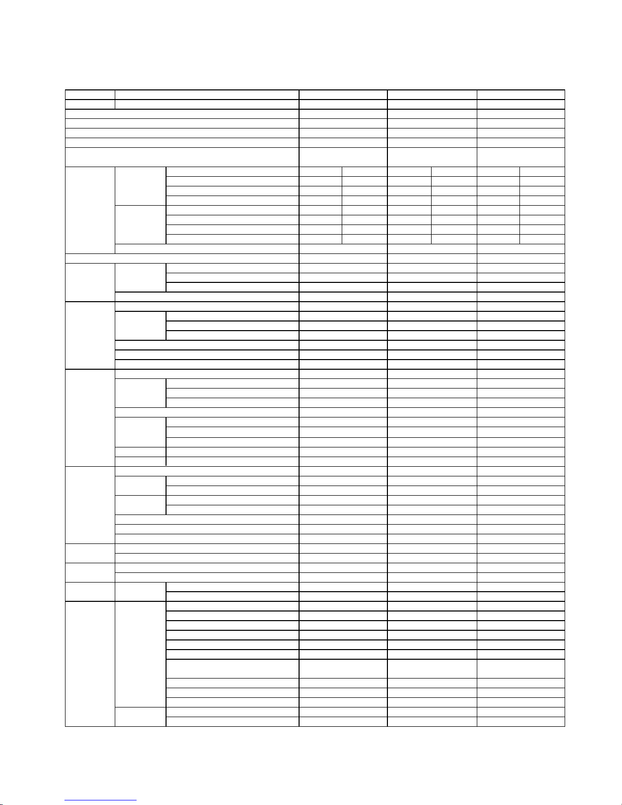
2-1. Specifications
2. SPECIFICATIONS
Unit model Indoor
Outdoor
Cooling capacity (kW)
Cooling capacity range (kW)
Heating capacity (kW)
Heating capacity range (kW)
Power supply
Electric Indoor Operation mode
characteristic Running current (A)
Power consumption (W)
Power factor (%)
Outdoor Operation mode
Running current (A)
Power consumption (W)
Power factor (%)
Starting current (A)
COP (Cooling / Heating) 4.20
Operating Indoor High (Cooling / Heating) (dB-A)
noise Medium (Cooling / Heating) (dB-A)
Low (Cooling / Heating) (dB-A)
Outdoor (Cooling / Heating) (dB-A)
Indoor unit Unit model
Dimention Height (mm)
Width (mm)
Depth (mm)
Net weight (kg)
Fan motor output (W)
Air flow rate (Cooling / Heating)
(m
3
/ min)
Outdoor unit Unit model
Dimention Height (mm)
Width (mm)
Depth (mm)
Net weight (kg)
Compressor Motor output (W)
Type
Model
Fan motor output (W)
Air flow rate (Cooling / Heating)
(m
3
/ min)
Piping Type
connection Indoor unit Liquid side (mm)
Gas side (mm)
Outdoor unit Liquid side (mm)
Gas side (mm)
Maximum length (m)
Maximun charge-less length (m)
Maximum height difference (m)
Refrigerant Name of refrigerant
Weight (kg)
Wiring Power supply
connection Interconnection 4 Wires:Includes earth 4 Wires:Includes earth 4 Wires:Includes earth
Usable temperature range Indoor (Cooling / Heating)
(
o
C)
Outdoor (Cooling / Heating)
(
o
C)
Accessory Indoor unit Installation plate
Wireless remote controller
Batteries
Toshiba New IAQ Filter
Install screw
Remote controller holder
Pan head wood screw
for Remote control holder
Insulate pipe
Installation manual
Owner's manual
Outdoor unit Drain nipple
Water-proof rubber cap
* The specification may be subject to change without notice for purpose of improvement.
8
1
2
*
1
1
1
*
1
1
2
2
*
Cooling Heating
0.20-0.19 0.24-0.22
25 30
56 57
Cooling
1
1
1
*
2
1
1
2
2
8
1
∅6.35
∅9.52
Flare connection
R32
8
1
2
1
1
2
2
1
1
1
*
*
Cooling Heating
0.27-0.24 0.30-0.28
35 40
60 60
R32
21-32/0-28
-10-46/-15-24
∅6.35
∅12.7
Flare connection
220
16
41
10.0/10.7
600
700
3.01/3.21
46/46
40/40
34/34
8.49-7.78
Heating
1Ph/50Hz/220-240V
1Ph/60Hz/220-230V
Cooling
RAS-B13U2FVG-E,-TR
*
21-32/0-28
-10-46/-15-24
220
16
41
8.5/9.2
600
700
3.33-3.36
40/40
33/33
27/27
5.06-4.65
1Ph/50Hz/220-240V
1Ph/60Hz/220-230V
Heating
RAS-B13U2FVG-E,-TR
R32
21-32/0-28
-10-46/-15-24
∅6.35
∅9.52
Flare connection
220
16
41
7.8/8.5
600
700
4.20/4.27
39/39
32/32
26/26
54
Cooling
3.04-2.78
56
Heating
0.20-0.19
25
1Ph/50Hz/220-240V
1Ph/60Hz/220-230V
Cooling Heating
0.17-0.15
20
RAS-B10U2FVG-E,-TR
*
*
RAS-B13U2FVG-E,-TR
RAS-B13U2FVG-E,-TRRAS-B10U2FVG-E,-TR
*
*
*
*
*
*
*
*
*
*
*
*
*
*
*
*
*
*
*
*
*
*
*
*
*
*
*
*
*
*
*
*
*
*
*
*
*
*
*
*
*
*
*
*
*
*
*
*
*
*
*
*
*
*
*
*
*
*
*
*
*
*
*
* *
* *
* *
* *
*
*
*
*
*
*
*
* * * *
*
*
FILE NO. SVM-18048
- 7 -
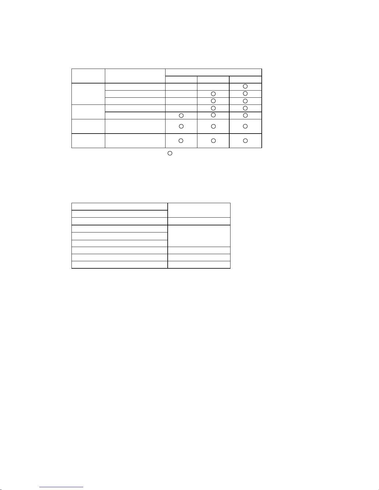
2-2. Combined multi-split outdoor unit
The multi-split outdoor units, which can be combined with B**U2FVG series indoor unit are as described below:
Outdoor
unit type
B18U2FVG B13U2FVG B10U2FVG
X
2-room Multi
outdoor unit
X
X
3-room Multi
outdoor unit
4-room Multi
outdoor unit
5-room Multi
outdoor unit
: Combination available
X : Combination unavailable
This service manual describes about B**U2FVG series indoor units only.
For the multi-split outdoor unit to be combined, refer to the service manual.
Outdoor unit
SVM-18051
SVM-18052
SVM-18053
SVM-18020
RAS-2M18U2AVG-E,-TR
RAS-2M14U2AVG-E,-TR
RAS-5M34U2AVG-E,-TR
RAS-4M27U2AVG-E,-TR
RAS-3M26U2AVG-E,-TR
File name
Heat Pump Model
Combined outdoor unit
model name
Indoor unit model name
RAS-3M18U2AVG-E,-TR
X
X
RAS-2M18U2AVG-E,-TR
RAS-2M14U2AVG-E,-TR
RAS-5M34U2AVG-E,-TR
RAS-4M27U2AVG-E,-TR
RAS-3M26U2AVG-E,-TR
RAS-3M18U2AVG-E,-TR
RAS-2M10U2AVG-E,-TR
SVM-18005
RAS-2M10U2AVG-E,-TR
FILE NO. SVM-18048
- 8 -

3. REFRIGERANT R32
This air conditioner adopts the new refrigerant HFC
(R32) which does not damage the ozone layer.
The next section describes the precautions for air
conditioner using the new refrigerant. Conforming to
contents of the next section together with the general
cautions included in this manual, perform the correct
and safe work.
3-1. Safety During Installation/Servicing
The basic installation servicing work procedures are
the same as conventional R410A models.
As R32’s pressure is about 1.6 times higher than that
of R22, improper installation/servicing may cause a
serious trouble. By using tools and materi-als exclusive
for R32, it is necessary to carry out installation/
servicing safely while taking the following precautions
into consideration.
1. Never use refrigerant other than R32 in an air
conditioner which is designed to operate with R32.
If other refrigerant than R32 is mixed, pressure in
the refrigeration cycle becomes abnormally high,
and it may cause personal injury, etc. by a rupture.
2. Confirm the used refrigerant name, and use tools
and materials exclusive for the refrigerant.
The refrigerant name R32 is indicated on the visible
place of the outdoor unit of the air conditioner using
R32 as refrigerant. To prevent mischarging, the
diameter of the service port differs from that of R22.
R32 and other HFCs are heavier than air, and
therefore they are inclined to settle near the floor
surface.
If the gas fills up the room or the bottom part of a
room, it may also cause oxygen deficiency and may
reach its combustion concentration.
In order to prevent oxygen deficiency and R32
combustion, keep the room well-ventilated for a
healthy work environment.
In particular, using HFCs in a basement room or
confined area creates a higher risk; be sure to
furnish the room with local exhaust ventilation.
If a refrigerant leak is confirmed in a room an
inadequately ventilated location, do not use a flame
until the area has been ventilated appropriately and
the work environment has been improved.
The same applies in case of brazing, ensure
appropriate ventilation to prevent oxygen deficiency
and R32 combustion.
Check that there are no dangerous or combustible
items nearby, and ensure a fire extinguisher is close
at hand.
Keep a sufficient distance away from causes of fire
(ignition sources) such as gas-burning equipment
and electric heaters in places where installation,
repairs, or similar work on air-conditioning
equipment is performed.
3. If a refrigeration gas leakage occurs during
installation/servicing, be sure to ventilate fully.
If the refrigerant gas comes into contact with fire, a
poisonous gas may occur.
4. When installing or removing an air conditioner, do
not allow air moisture dust or oil to remain in the
refrigeration cycle. Otherwise, pressure in
the refrigeration cycle may become abnormally high
so that a rupture or personal injury may be caused.
5. After completion of installation work, check to make
sure that there is no refrigeration gas leakage.
If the refrigerant gas leaks into the room, coming
into contact with fire in the fan-driven heater, space
heater, etc., a poisonous gas may occur
6. When an air conditioning system charged with a
large volume of refrigerant is installed in a small
room, it is necessary to exercise care so that, even
when refrigerant leaks, its concentration does not
exceed the marginal level.
If the refrigerant gas leakage occurs and its
concentration exceeds the marginal level, an
oxygen starvation accident may result.
7. Be sure to carry out installation or removal
according to the installation manual.
Improper installation may cause refrigeration
trouble, water leakage, electric shock, fire, etc.
8. Unauthorized modifications to the air conditioner
may be dangerous. If a breakdown occurs please
call a qualified air conditioner technician or
electrician.
Improper repair's may result in water leakage,
electric shock and fire, etc.
3-2. Refrigerant Piping Installation
3-2-1. Piping Materials and Joints Used
For the refrigerant piping installation, copper pipes
and joints are mainly used. Copper pipes and joints
suitable for the refrigerant must be chosen and
installed. Furthermore, it is necessary to use clean
copper pipes and joints whose interior surfaces are
less affected by contaminants.
1. Copper Pipes
It is necessary to use seamless copper pipes which
are made of either copper or copper alloy and it is
desirable that the amount of residual oil is less than
40 mg/10 m. Do not use copper pipes having a
collapsed, deformed or discolored portion
(especially on the interior surface).
Otherwise, the expansion valve or capillary tube
may become blocked with contaminants.
As an air conditioner using R32 incurs pres-sure
higher than when using R22, it is necessary to
choose adequate materials.
Thicknesses of copper pipes used with R32 are as
shown in Table 3-2-1. Never use copper pipes
thinner than 0.8 mm even when it is available on
the market.
FILE NO. SVM-18048
- 9 -
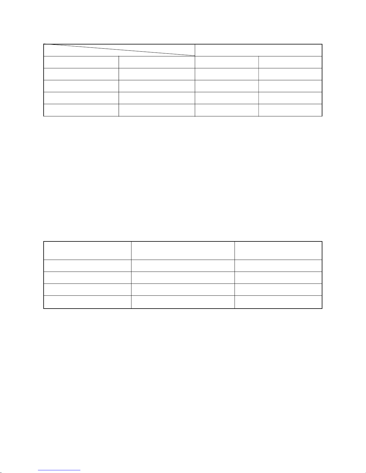
Table 3-2-1 Thicknesses of annealed copper pipes
Nominal diameter
1/4
3/8
1/2
5/8
Outer diameter (mm)
6.35
9.52
12.70
15.88
Thickness (mm)
R32 R22
0.80 0.80
0.80 0.80
0.80 0.80
1.00 1.00
2. Joints
For copper pipes, flare joints or socket joints are used. Prior to use, be sure to remove all contaminants.
a) Flare Joints
Flare joints used to connect the copper pipes cannot be used for pipings whose outer diameter exceeds
20 mm. In such a case, socket joints can be used.
Sizes of flare pipe ends, flare joint ends and flare nuts are as shown in Tables 3-2-3 to 3-2-6 below.
b) Socket Joints
Socket joints are such that they are brazed for connections, and used mainly for thick pipings whose
diameter is larger than 20 mm.
Thicknesses of socket joints are as shown in Table 3-2-2.
Table 3-2-2 Minimum thicknesses of socket joints
Nominal diameter
1/4
3/8
1/2
5/8
Reference outer diameter of
copper pipe jointed (mm)
6.35
9.52
12.70
15.88
Minimum joint thickness
(mm)
0.50
0.60
0.70
0.80
3-2-2. Processing of Piping Materials
When performing the refrigerant piping installation, care should be taken to ensure that water or dust does not
enter the pipe interior, that no other oil than lubricating oils used in the installed air-water heat pump is used,
and that refrigerant does not leak. When using lubricating oils in the piping processing, use such lubricating oils
whose water content has been removed. When stored, be sure to seal the container with an airtight cap or any
other cover.
1. Flare processing procedures and precautions
a) Cutting the Pipe
By means of a pipe cutter, slowly cut the pipe so that it is not deformed.
b) Removing Burrs and Chips
If the flared section has chips or burrs, refrigerant leakage may occur.
Carefully remove all burrs and clean the cut surface before installation.
c) Insertion of Flare Nut
FILE NO. SVM-18048
- 10 -
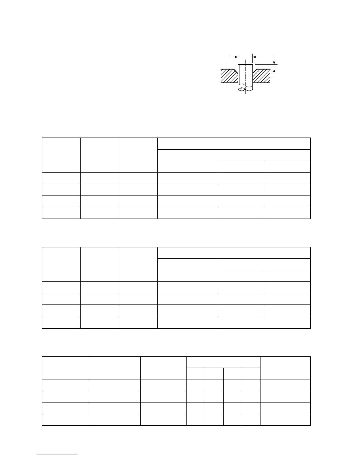
A
ØD
d) Flare Processing
Make certain that a clamp bar and copper
pipe have been cleaned.
By means of the clamp bar, perform the flare
processing correctly.
Use either a flare tool for R32 or conventional flare tool.
Flare processing dimensions differ according
to the type of flare tool. When using a conventional flare tool, be sure to secure “dimension A” by using a gauge for size adjustment.
Fig. 3-2-1 Flare processing dimensions
Table 3-2-3 Dimensions related to flare processing for R32
Nominal
diameter
1/4
3/8
1/2
5/8
Outer
diameter
(mm)
6.35
9.52
12.70
15.88
Thickness
(mm)
0.8
0.8
0.8
1.0
A (mm)
Flare tool for R32
clutch type
0 to 0.5
0 to 0.5
0 to 0.5
0 to 0.5
Conventional flare tool
Clutch type Wing nut type
1.0 to 1.5 1.5 to 2.0
1.0 to 1.5 1.5 to 2.0
1.0 to 1.5 2.0 to 2.5
1.0 to 1.5 2.0 to 2.5
Table 3-2-4 Dimensions related to flare processing for R22
Nominal
diameter
1/4
3/8
1/2
5/8
Outer
diameter
(mm)
6.35
9.52
12.70
15.88
Thickness
(mm)
0.8
0.8
0.8
1.0
A (mm)
Flare tool for R22
clutch type
0 to 0.5
0 to 0.5
0 to 0.5
0 to 0.5
Conventional flare tool
Clutch type Wing nut type
0.5 to 1.0 1.0 to 1.5
0.5 to 1.0 1.0 to 1.5
0.5 to 1.0 1.5 to 2.0
0.5 to 1.0 1.5 to 2.0
Table 3-2-5 Flare and flare nut dimensions for R32
Nominal
diameter
1/4
3/8
1/2
5/8
Outer diameter
(mm)
6.35
9.52
12.70
15.88
Thickness
(mm)
0.8
0.8
0.8
1.0
Dimension (mm)
ABCD
9.1 9.2 6.5 13
13.2 13.5 9.7 20
16.6 16.0 12.9 23
19.7 19.0 16.0 25
Flare nut width
(mm)
17
22
26
29
FILE NO. SVM-18048
- 11 -
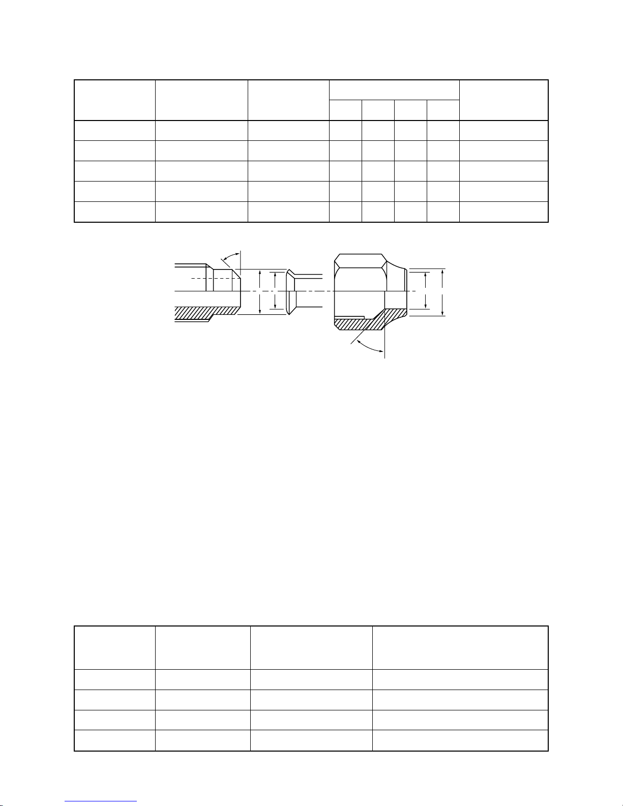
43° to 45°
45° to 46°
B A
C
D
Table 3-2-6 Flare and flare nut dimensions for R22
Nominal
diameter
1/4
3/8
1/2
5/8
3/4
Outer diameter
(mm)
6.35
9.52
12.70
15.88
19.05
Thickness
(mm)
0.8
0.8
0.8
1.0
1.0
Dimension (mm)
ABCD
9.0 9.2 6.5 13
13.0 13.5 9.7 20
16.2 16.0 12.9 20
19.7 19.0 16.0 23
23.3 24.0 19.2 34
Flare nut width
(mm)
17
22
24
27
36
Fig. 3-2-2 Relations between flare nut and flare seal surface
2. Flare Connecting Procedures and Precautions
a) Make sure that the flare and union portions do not have any scar or dust, etc.
b) Correctly align the processed flare surface with the union axis.
c) Tighten the flare with designated torque by means of a torque wrench. The tightening torque for R32 is
the same as that for conventional R22. Incidentally, when the torque is weak, the gas leakage may occur.
When it is strong, the flare nut may crack and may be made non-removable. When choosing the tightening torque, comply with values designated by manufacturers. Table 3-2-7 shows reference values.
NOTE :
When applying oil to the flare surface, be sure to use oil designated by the manufacturer.
If any other oil is used, the lubricating oils may deteriorate and cause the compressor to burn out.
Table 3-2-7 Tightening torque of flare for R32 [Reference values]
Nominal
diameter
1/4
3/8
1/2
5/8
Outer diameter
(mm)
6.35
9.52
12.70
15.88
Tightening torque
N•m (kgf•cm)
14 to 18 (140 to 180)
33 to 42 (330 to 420)
50 to 62 (500 to 620)
63 to 77 (630 to 770)
Tightening torque of torque
wrenches available on the market
N•m (kgf•cm)
16 (160), 18 (180)
42 (420)
55 (550)
65 (650)
FILE NO. SVM-18048
- 12 -
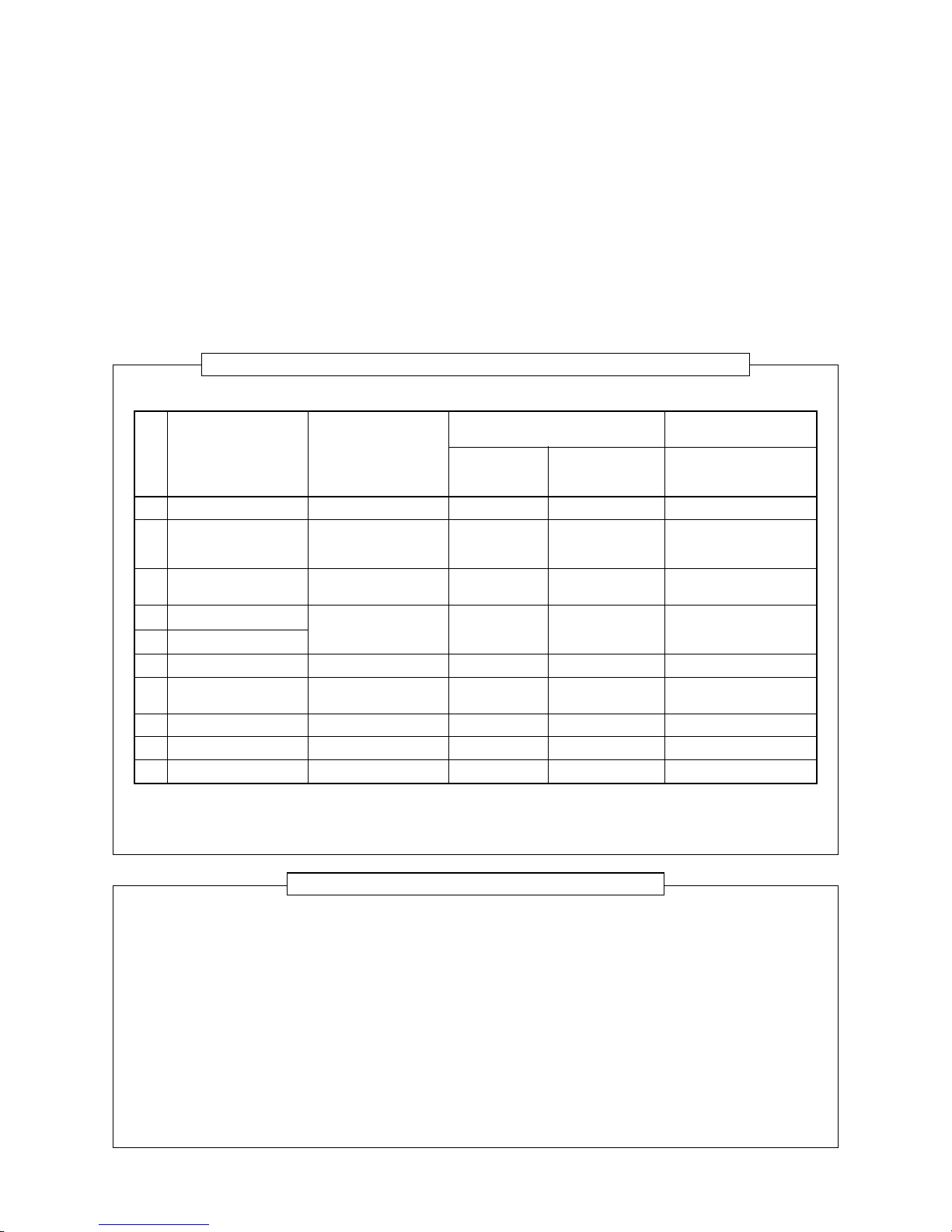
Tools exclusive for R410A (The following tools for R32 are required.)
Tools whose specifications are changed for R32 and their interchangeability
No.
1
2
3
4
5
6
7
8
9
10
Used tool
Flare tool
Copper pipe gauge for
adjusting projection
margin
Torque wrench
(For Ø12.7)
Gauge manifold
Charge hose
Vacuum pump adapter
Electronic balance for
refrigerant charging
Refrigerant cylinder
Leakage detector
Charging cylinder
Usage
Pipe flaring
Flaring by
conventional flare tool
Connection of flare nut
Evacuating, refrigerant
charge, run check, etc.
Vacuum evacuating
Refrigerant charge
Refrigerant charge
Gas leakage check
Refrigerant charge
R32
air-water heat pump installation
Existence of
new equipment
for R32
Ye s
Ye s
Ye s
Ye s
Ye s
Ye s
Ye s
Ye s
(Note 2)
Whether conventional equipment
can be used
*(Note 1)
*(Note 1)
×
×
×
×
×
×
×
Conventional air-water
heat pump installation
Whether new equipment
can be used with
conventional refrigerant
¡
*(Note 1)
×
×
¡
¡
×
¡
×
(Note 1) When flaring is carried out for R32 using the conventional flare tools, adjustment of projection
margin is necessary. For this adjustment, a copper pipe gauge, etc. are necessary.
(Note 2) Charging cylinder for R32 is being currently developed.
General tools (Conventional tools can be used.)
In addition to the above exclusive tools, the following equipments which serve also for R22 are necessary
as the general tools.
1. Vacuum pump
Use vacuum pump by attaching
vacuum pump adapter.
2. Torque wrench (For Ø6.35, Ø9.52)
3. Pipe cutter
4. Reamer
5. Pipe bender
6. Level vial
7. Screwdriver (+, –)
8. Spanner or Monkey wrench
9. Hole core drill (Ø65)
10. Hexagon wrench
(Opposite side 4mm)
11. Tape measure
12. Metal saw
Also prepare the following equipments for other installation method and run check.
1. Clamp meter
2. Thermometer
3. Insulation resistance tester
4. Electroscope
3-3. Tools
3-3-1. Required Tools
The service port diameter of packed valve of the outdoor unit in the air-water heat pump using R32 is
changed to prevent mixing of other refrigerant. To reinforce the pressure-resisting strength, flare processing
dimensions and opposite side dimension of flare nut (For Ø12.7 copper pipe) of the refrigerant piping are
lengthened.
The used refrigerating oil is changed, and mixing of oil may cause a trouble such as generation of sludge,
clogging of capillary, etc. Accordingly, the tools to be used are classified into the following three types.
1. Tools exclusive for R32 (Those which cannot be used for conventional refrigerant (R22))
2. Tools exclusive for R32, but can be also used for conventional refrigerant (R22)
3. Tools commonly used for R32 and for conventional refrigerant (R22)
The table below shows the tools exclusive for R32 and their interchangeability
.
FILE NO. SVM-18048
- 13 -
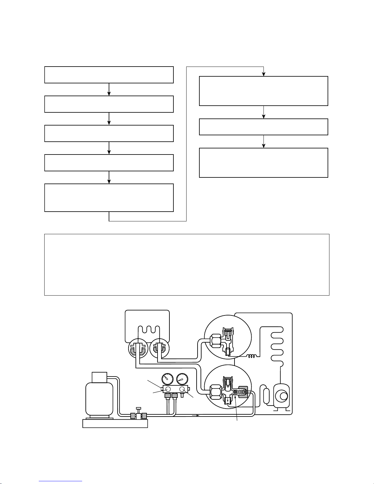
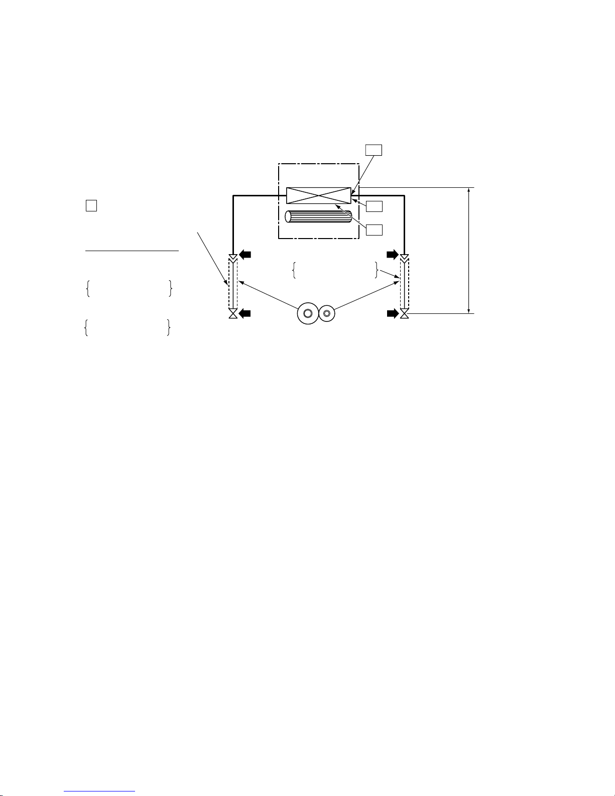
Connect the charge hose to packed valve service
port at the outdoor unit’s gas side.
Recover the refrigerant, and check no refrigerant
remains in the equipment.
(For refrigerant charging, see the figure below.)
Connect the charge hose to the vacuum pump
adapter.
Open fully both packed valves at liquid and gas
sides.
Place the handle of the gauge manifold Low in the
fully opened position, and turn on the vacuum pump’s
power switch. Then, evacuating the refrigerant in the
cycle.
When the compound gauge’s pointer has indicated
–0.1 Mpa (–76 cmHg), place the handle Low in the
fully closed position, and turn off the vacuum pump’s
power switch.
Keep the status as it is for 1 to 2 minutes, and ensure
that the compound gauge’s pointer does not return.
Set the refrigerant cylinder to the electronic balance,
connect the connecting hose to the cylinder and the
connecting port of the electronic balance, and charge
liquid refrigerant.
(Indoor unit)
(Outdoor unit)
Opened
Opened
Refrigerant cylinder
(with siphon)
Check valve
Open/close
valve for charging
Electronic balance for refrigerant charging
Opened
Closed
Service port
3-4. Recharging of Refrigerant
When it is necessary to recharge refrigerant, charge the specified amount of new refrigerant according to the
following steps.
1. Never charge refrigerant exceeding the specified amount.
2. If the specified amount of refrigerant cannot be charged, charge refrigerant bit by bit in COOL mode.
3. Do not carry out additional charging.
When additional charging is carried out if refrigerant leaks, the refrigerant composition changes in the
refrigeration cycle, that is characteristics of the air conditioner changes, refrigerant exceeding the
specified amount is charged, and working pressure in the refrigeration cycle becomes abnormally high
pressure, and may cause a rupture or personal injury.
Fig. 3-4-1 Configuration of refrigerant charging
FILE NO. SVM-18048
- 14 -
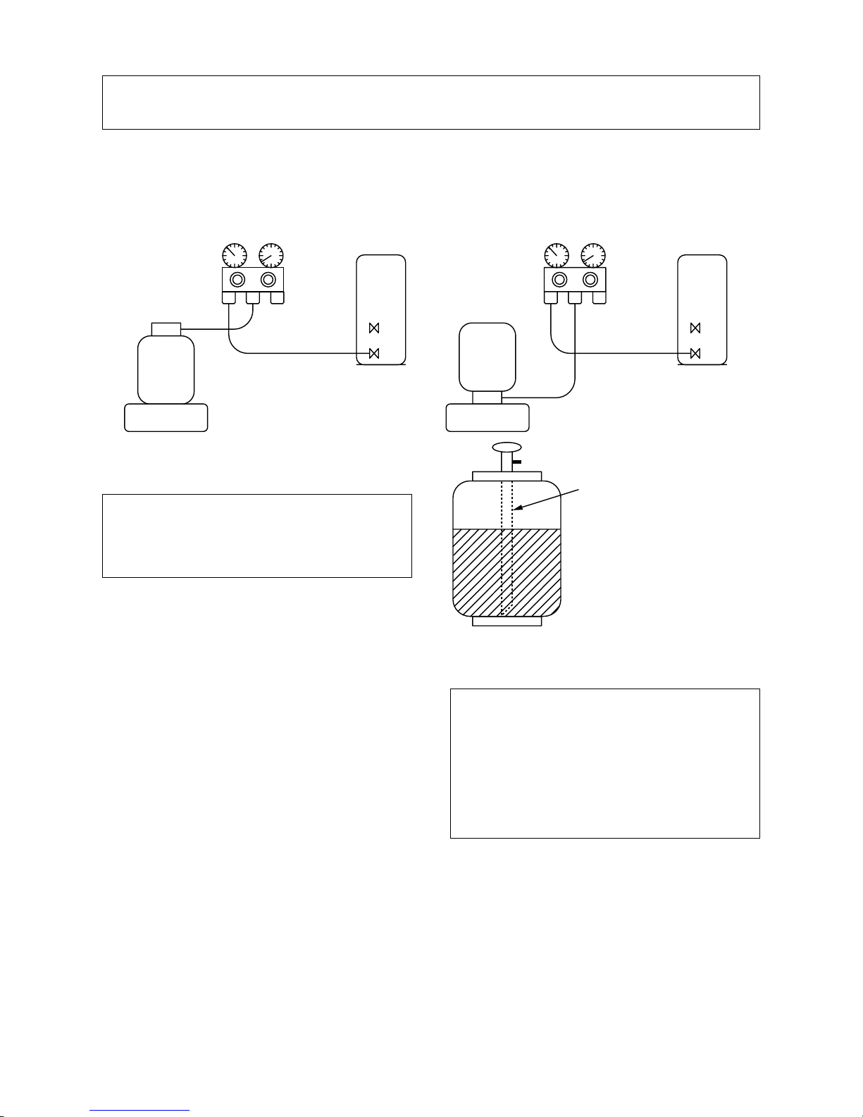
Gauge manifold
[ Cylinder with siphon ] [ Cylinder without siphon ]
OUTDOOR unit
Gauge manifold
OUTDOOR unit
Refrigerant
cylinder
Electronic
balance
Refrigerant
cylinder
Electronic
balance
Siphon
1. Be sure to make setting so that liquid can be charged.
2. When using a cylinder equipped with a siphon, liquid can be charged without turning it upside down.
It is necessary for charging refrigerant under condition of liquid because R32 is mixed type of refrigerant.
Accordingly, when charging refrigerant from the refrigerant cylinder to the equipment, charge it turning the
cylinder upside down if cylinder is not equipped with siphon.
R32 refrigerant is HFC mixed refrigerant.
Therefore, if it is charged with gas, the composition of the charged refrigerant changes and the
characteristics of the equipment varies.
3-5. Brazing of Pipes
3-5-1. Materials for Brazing
1. Silver brazing filler
Silver brazing filler is an alloy mainly composed
of silver and copper. It is used to join iron, copper
or copper alloy, and is relatively expensive though
it excels in solderability.
2. Phosphor bronze brazing filler
Phosphor bronze brazing filler is generally used
to join copper or copper alloy.
3. Low temperature brazing filler
Low temperature brazing filler is generally called
solder, and is an alloy of tin and lead. Since it is
weak in adhesive strength, do not use it for
refrigerant pipes.
1. Phosphor bronze brazing filler tends to react
with sulfur and produce a fragile compound
water solution, which may cause a gas
leakage. Therefore, use any other type of
brazing filler at a hot spring resort, etc., and
coat the surface with a paint.
2. When performing brazing again at time of
servicing, use the same type of brazing filler.
3-5-2. Flux
1. Reason why flux is necessary
• By removing the oxide film and any foreign
matter on the metal surface, it assists the flow
of brazing filler.
• In the brazing process, it prevents the metal
surface from being oxidized.
• By reducing the brazing filler’s surface tension,
the brazing filler adheres better to the treated
metal.
Fig. 3-4-2
FILE NO. SVM-18048
- 15 -
Nitrogen gas
cylinder
Pipe
Flow meter
M
Stop valve
From Nitrogen cylinder
Nitrogen
gas
Rubber plug
2. Characteristics required for flux
• Activated temperature of flux coincides with the
brazing temperature.
• Due to a wide effective temperature range, flux
is hard to carbonize.
• It is easy to remove slag after brazing.
• The corrosive action to the treated metal and
brazing filler is minimum.
• It excels in coating performance and is harmless to the human body.
As the flux works in a complicated manner as
described above, it is necessary to select an
adequate type of flux according to the type and
shape of treated metal, type of brazing filler and
brazing method, etc.
3. Types of flux
• Noncorrosive flux
Generally, it is a compound of borax and boric
acid.
It is effective in case where the brazing temperature is higher than 800°C.
• Activated flux
Most of fluxes generally used for silver brazing
are this type.
It features an increased oxide film removing
capability due to the addition of compounds
such as potassium fluoride, potassium chloride
and sodium fluoride to the borax-boric acid
compound.
4. Piping materials for brazing and used
brazing filler/flux
1. Do not enter flux into the refrigeration cycle.
2. When chlorine contained in the flux remains
within the pipe, the lubricating oil deteriorates.
Therefore, use a flux which does not contain
chlorine.
3. When adding water to the flux, use water
which does not contain chlorine (e.g. distilled
water or ion-exchange water).
4. Remove the flux after brazing.
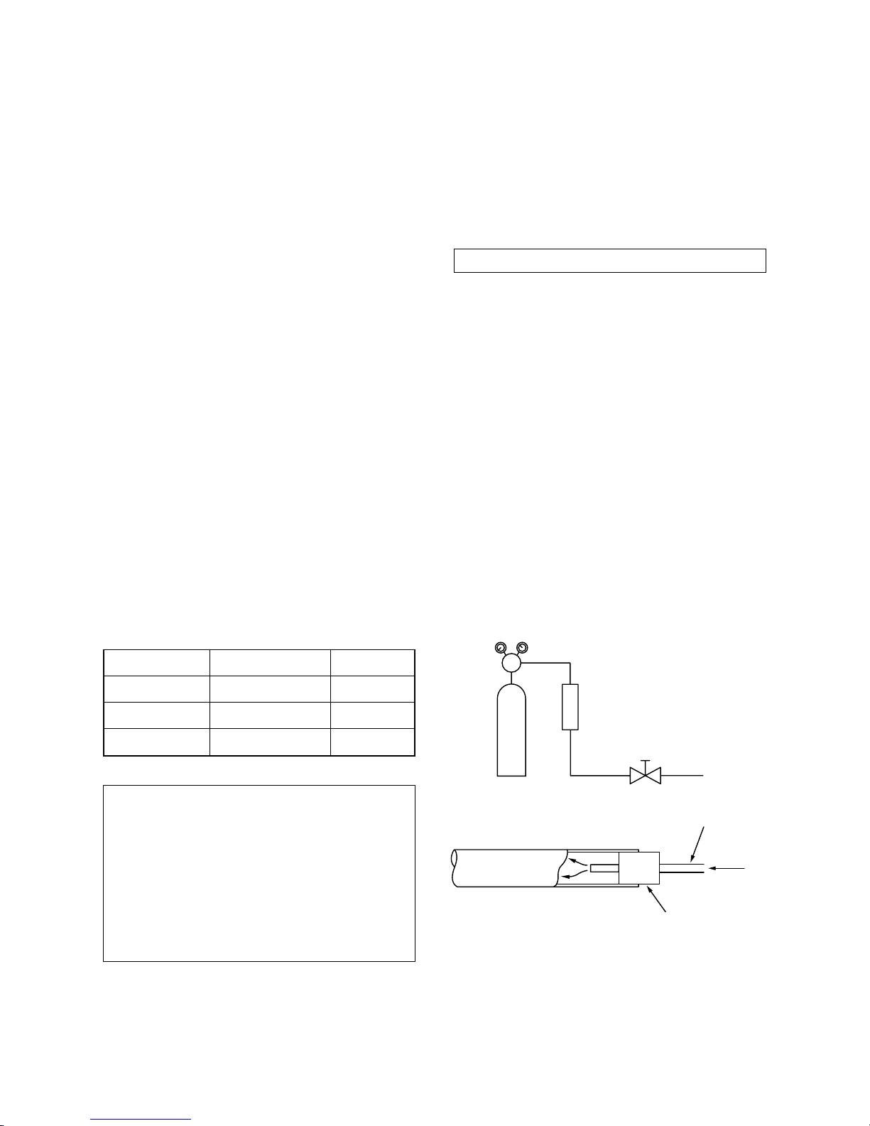
3-5-3. Brazing
As brazing work requires sophisticated techniques,
experiences based upon a theoretical knowledge, it
must be performed by a person qualified.
In order to prevent the oxide film from occurring in
the pipe interior during brazing, it is effective to
proceed with brazing while letting dry Nitrogen gas
(N2) flow.
Never use gas other than Nitrogen gas.
1. Brazing method to prevent oxidation
1) Attach a reducing valve and a flow-meter to
the Nitrogen gas cylinder.
2) Use a copper pipe to direct the piping material, and attach a flow-meter to the cylinder.
3) Apply a seal onto the clearance between the
piping material and inserted copper pipe for
Nitrogen in order to prevent backflow of the
Nitrogen gas.
4) When the Nitrogen gas is flowing, be sure to
keep the piping end open.
5) Adjust the flow rate of Nitrogen gas so that it
is lower than 0.05 m3/Hr or 0.02 MPa
(0.2kgf/cm2) by means of the reducing valve.
6) After performing the steps above, keep the
Nitrogen gas flowing until the pipe cools down
to a certain extent (temperature at which
pipes are touchable with hands).
7) Remove the flux completely after brazing.
Fig. 3-5-1 Prevention of oxidation during brazing
Piping material
Copper - Copper
Copper - Iron
Iron - Iron
Used brazing filler
Phosphor copper
Silver
Silver
Used flux
Do not use
Paste flux
Vapor flux
FILE NO. SVM-18048
- 16 -
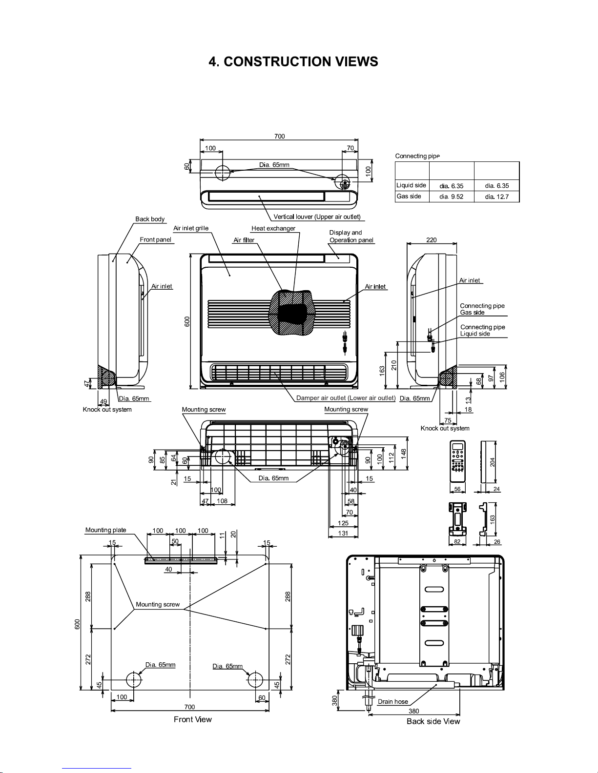
Indoor Unit
4-1.
B10
U2FVG series
B13U2FVG series
B18U2FVG series
FILE NO. SVM-18048
- 17 -
RAS-B10 U2FVG-E,-TR
RAS-B13 U2FVG-E,-TR
RAS-B18 U2FVG-E,-TR
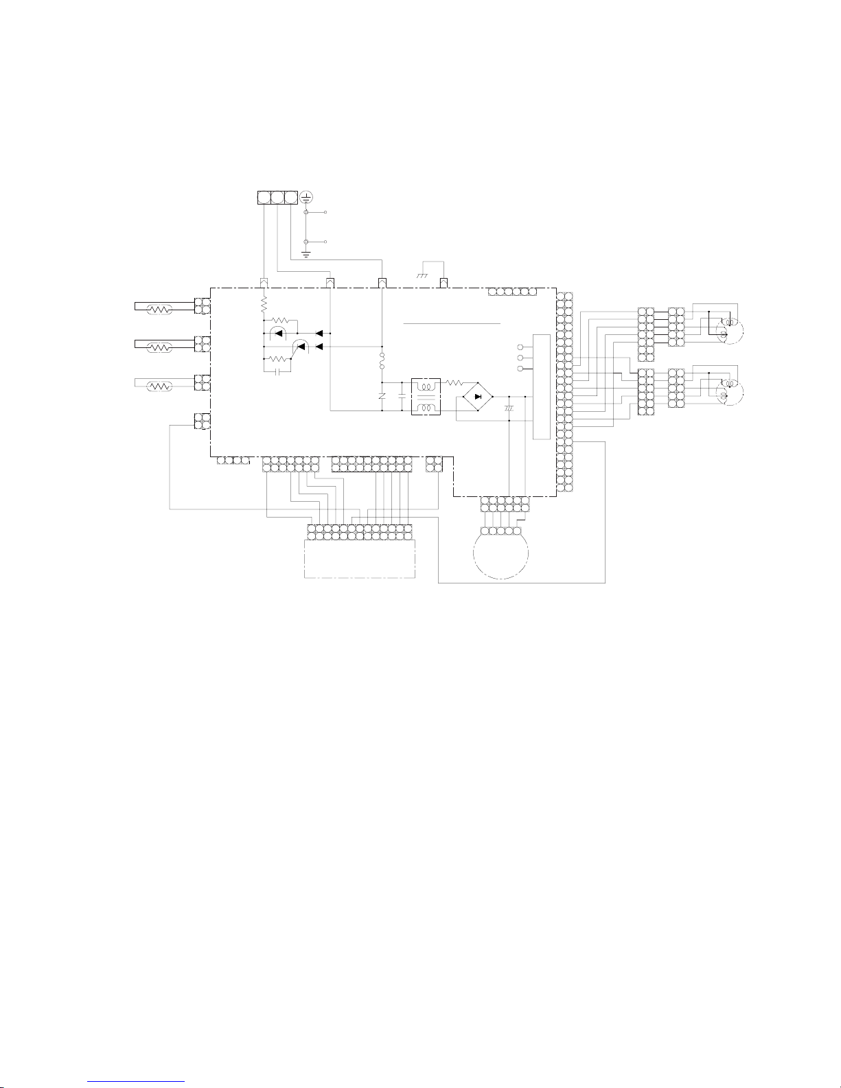
5. WIRING DIAGRAM
ORG
YEL : YELLOW
BLU : BLUE
WHI : W HITE
ORG : ORANGE
GRN & YEL :
GREEN & YELLOW
BLK : BLACK
RED : RED
Color indication
POWER SUPPLY
(From outdoor unit)
1∅ 220-240~ ,50Hz
1∅ 220-230~ ,60Hz
4
5
1
2
3
6
7
8
9
10
11
12
13
14
15
16
17
18
19
20
21
22
23
24
25
26
9
10
11
12
13
14
15
16
17
18
20
4
5
2
1
3
4
5
2
1
3
4
5
2
1
3
4
5
2
1
3
4
5
2
1
3
4
5
2
1
3
4
5
2
1
3
4
5
2
1
3
13
13
8
12 11 10 9 8
12 11
10 9
5
67
567
44123
12
3
4455667
7
112 3 10 9 8
445
5
67
11223
3
CN212
1 432
HA
(WHI)
1
12
121
2
121
2
121
2
1
22
5
5
6634 1
34 1
3
2 1
Wireless Unit
Assembly
WP-021
CN381
(WHI)
CN301
(WHI)
CN201
(WHI)
CN261
(WHI)
CN401
(RED)
CN51
(WHI)
CN604
(WHI)
CN601
(WHI)
CN603
(YEL)
CN602
(BLU)
CN21
Main P.C Board
MCC-5068A
Power Supply Circuit
DC5V
DC12V
+
Fuse F01
T3.15A
250VAC
CN501 CN03 CN01
456112
~
-
+
~
CN801
R01
Varistor
Line
Filter
Thermo Sensor
(TA)
Heat Exch anger Sens or
(TCJ)
Heat Exch anger Sens or
(TC)
Indoor Terminal Block
RED
WHI
BLK
Heat
Exchanger
Fan Motor Base
GRN&YEL
GRN&YEL
SHEET
METAL
BLK
WHI
YEL
YEL
YEL
YEL
WHI
YEL
YEL
YEL
YEL
RED
BLU
BLU
BLU
BLU
BLU
ORG
ORG
BLU
BLU
WHI
45 233
DC MOTOR
Fan Motor
BLU
YEL
WHI
BLK
RED
Stepper motor
(Vertical air flow louver)
Stepper motor
(Damper)
RED
BLK
BLK
BLK
BLK
BLK
BLK
DC29V
3
FILE NO. SVM-18048
- 18 -
6. SPECIFICATIONS OF ELECTRICAL PARTS
6-1. Indoor Unit
No.
Fan motor (for indoor)
2 Room temp. sensor (TA-sensor)
10kΩ at 25°C
3
Heat exchanger temp. sensor (TC-sensor)
10kΩ
at 25°C
5 Louver motor
Output (Rated), 16 poles, DC12V
( - )
( -)
MP24Z3N
ICF-340-41-1 DC340, 41W
Parts n ame
1
Specif icat io nsType
6
Dumper motor
Output (Rated), 16 poles, DC12V
MP24Z3N
4
10kΩ
at 25°C
( -)
Heat exchanger temp. sensor (TCJ-sensor)
FILE NO. SVM-18048
- 19 -
7. REFRIGERANT CYCLE DIAGRAM
Outer dia. : 9.52mm
Thickness : 0.8mm
T1
Temp. measurement
TC
TA
INDOOR UNIT
Indoor heat
exchanger
Cross flow fan
Deoxidized copper pipe
Outer dia. : 6.35mm
Thickness : 0.8mm
Sectional shape
of heat insulator
Allowable height
difference : 10m
Allowable pipe length
Max. : *1
Min. : *1
Chargeless : *1
Charge : *1
*1 : Refer to the service manual of multi outdoor unit to be combined.
For RAS-B18U2FVG Series
Outer dia. : 12.7mm
Thickness : 0.8mm
P Pressure measurement
Gauge attaching port
Vacuum pump connecting port
Deoxidized copper pipe :
For RAS-B10U2FVG Series
RAS-B13U2FVG Series
7-1. Refrigerant Cycle Diagram
FILE NO. SVM-18048
- 20 -
7-2. Operation Data
<Cooling>
Heat exchanger pipe
temp.
Indoor fan
mode
Outdoor fan
mode
Indoor Outdoor T1 (°C) T2 (°C)
B10U2FVG-E,-TR
* * * * * *
B13U2FVG-E,-TR
* * * * * *
B18U2FVG-E,-TR
* * * * * *
<Heating>
Heat exchanger pipe
temp.
Indoor fan
mode
Outdoor fan
mode
Indoor Outdoor T1 (°C) T2 (°C)
* * * * * *
* * * * * *
* * * * * *
NOTES :
* Refer to service manual of outdoor unit which combined.
27/19 35/-
Compressor
revolution
(rps)
Tempeature
condition(°C)
Model name
RAS-
Standard
pressure
P (MPa)
Tempeature
condition(°C)
Model name
RAS-
Standard
pressure
P (MPa)
Compressor
revolution
(rps)
20/- 7/6
B10U2FVG-E,-TR
B13U2FVG-E,-TR
B18U2FVG-E,-TR
FILE NO. SVM-18048
- 21 -
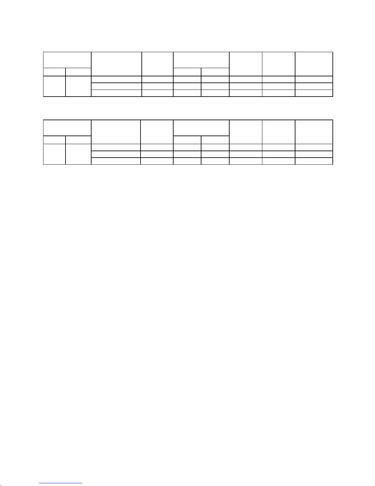
8. CONTROL BLOCK DIAGRAM
8-1. Indoor Unit
M.C.U.
Indoor Unit Control Unit
Serial Signal Communication
(Operation Command and Information)
Serial Signal Transmitter/Receiver
Converter
(D.C circuit)
Noise Filter
Indoor
Fan Motor
Louver
Motor
Louver Motor
Drive Control
Indoor Fan
Motor Control
Initializing Circuit
Clock Frequency
Oscillator Circuit
Power Supply
Circuit
Infrared Rays, 36.7kHz
Fan Speed Selection
ON TIMER Setting
OFF TIMER Setting
Louver AUTO Swing
Louver Direction Setting
REMOTE CONTROL
FLOOR (ON/OFF)
ECO
Heat Exchanger Sensor (TC)
Room Temperature Sensor (TA)
Infrared Rays Signal Receiver
and Indication
Functions
• Cold draft preventing Function
• 3-minute Delay at Restart for Compressor
• Fan Motor Starting Control
•
Processing
(Temperature Processing)
•
Timer / Weekly Timer
• Serial Signal Communication
• Clean Function
Heat Exchanger Sensor (TCJ)
Power Supply
From Outdoor Unit
Damper
Drive Control
Damper
Motor
•
Power Selection
Hi-POWER
COMPORT SLEEP
Remote Control
Operation (START/STOP)
Operation Mode Selection
AUTO, COOL, DRY, HEAT
Thermo. Setting
FILE NO. SVM-18048
- 22 -

.
.
.
9. OPERATION DESCRIPTION
9-1. Outline of Air Conditioner Control
This air conditioner is a capacity-variable type air
conditioner, which uses DC motor for the indoor fan
motor and the outdoor fan motor. And the capacityproportional control compressor which can change the
motor speed is mounted. The DC motor drive circuit
is mounted to the indoor unit. The compressor and
the inverter to control fan motor are mounted to the
outdoor unit.
The entire air conditioner is mainly controlled by the
indoor unit controller.
The indoor unit controller drives the indoor fan motor
based upon command sent from the remote controller
or indoor unit display buttons and transfers the
operation command to the outdoor unit controller.
The outdoor unit controller receives operation command from the indoor unit side, and controls the
outdoor fan and the pulse Modulating valve. (P.M.V)
Besides, detecting revolution position of the compressor motor, the outdoor unit controller controls speed of
the compressor motor by controlling output voltage of
the inverter and switching timing of the supply power
(current transfer timing) so that motors drive according
to the operation command.
And then, the outdoor unit controller transfers reversely
the operating status information of the outdoor unit to
control the indoor unit controller.
2. Role of outdoor unit controller
Receiving the operation command signal (Serial
signal) from the indoor unit controller, the outdoor
unit performs its role.
• Compressor operation control
• Operation control of outdoor fan motor
• P.M.V. control
• 4-way valve control
Operations followed to judgment
of serial signal from indoor side.
• Detection of inverter input current and current
release operation
• Over-current detection and prevention operation
to IGBT module (Compressor stop function)
• Compressor and outdoor fan stop function when
serial signal is off (when the serial signal does not
reach the board assembly of outdoor control by
trouble of the signal system)
• Transferring of operation information (Serial
signal) from outdoor unit controller to indoor unit
controller
• Detection of outdoor temperature and operation
revolution control
• Defrost control in heating operation (Temp.
measurement by outdoor heat exchanger and
control for 4-way valve and outdoor fan)
3. Contents of operation command signal
(Serial signal) from indoor unit controller to
outdoor unit controller
The following three types of signals are sent from
the indoor unit controller.
• Operation mode set on the remote controller
• Compressor revolution command signal defined
by indoor temperature and set temperature
(Correction along with variation of room temperature and correction of indoor heat exchanger
temperature are added.)
• Temperature of indoor heat exchanger
• For these signals ([Operation mode] and [Com-
pressor revolution] indoor heat exchanger temperature), the outdoor unit controller monitors the
input current to the inverter, and performs the
followed operation within the range that current
does not exceed the allowable value.
4. Contents of operation command signal
(Serial signal) from outdoor unit controller
to indoor unit controller
The following signals are sent from the outdoor unit
controller.
• The current operation mode
• The current compressor revolution
• Outdoor temperature
• Existence of protective circuit operation
For transferring of these signals, the indoor unit
controller monitors the contents of signals, and
judges existence of trouble occurrence.
Contents of judgment are described below.
• Whether distinction of the current operation
status meets to the operation command signal
• Whether protective circuit operates
When no signal is received from the outdoor
unit controller, it is assumed as a trouble.
As the compressor adopts four-pole brushless
DC motor, the frequency of the supply power
from inverter to compressor is two-times cycles
of the actual number of revolution.
1. Role of indoor unit controller
The indoor unit controller judges the operation
commands from the remote control or indoor unit
display buttons, and assumesthe following functions.
• Judgment of suction air temperature of the indoor
heat exchanger by using the indoor temp. sensor.
(TA sensor)
• Judgment of the indoor heat exchanger temperature by using heat exchanger sensor (TC sensor)
(Prevent-freezing control, etc.)
• Louver motor control
• Indoor fan motor operation control
• LED (Light Emitting Diode) display control
• Transferring of operation command signal (Serial
signal) to the outdoor unit
• Reception of information of operation status
(Serial signal including outside temp. data) to the
outdoor unit and judgment/display of error
NOTE :
FILE NO. SVM-18048
- 23 -

FILE NO. SVM-18048
- 24 -
9-2. Operation Description
1. Basic operation ........................................................................................................... 25
1.
Operation control ................................................................................................... 25
2.
Cooling/Heating operation ..................................................................................... 26
3.AUTO operation ......................................................................................................26
4.
DRY operation ........................................................................................................ 27
2.
Indoor fan motor control ............................................................................................. 28
3.
4.
Capacity control .......................................................................................................... 31
5.
Current release control ............................................................................................... 31
6.
Release protective co
ntrol by temperature of indoor heat exchanger........................ 31
7.
Defrost
control (Only in heating operation) ................................................................ 31
8.
Air outlet selection ...................................................................................................... 33
9.
Lower air outlet louver control ..................................................................................... 34
10.
Upper air outlet louver control .................................................................................... 35
11.
EC
O operation ........................................................................................................... 36
13.
Discharge temperature control ................................................................................... 37
14.
Pulse Modulating valve (P.M.V.) control ...................................................................... 38
15.
Self-Cleaning function ................................................................................................. 39
16.
Selt-Cleaning function release .................................................................................... 40
17.
Remote-A or B selection ............................................................................................ 41
9-
3. Auto Restart Function .............................................................................................47
9-
3-1. How to Set the A u
to Restart Function .............................. ........................................47
9-
3-2. How to Cancel t
he Au to Restar t Function ................................................................. 48
9-3-3. Power Failure During Timer Operation .................................................................... 48
23.
FIL
TER Indicator ...............................................................................................43
9-
4. Remote Control .........................................................................................................49
9-4-1. Remote control and its functions ................................................................................. 49
9-4-2. Operation of remote control ...................................................................................... 49
18.
QUIET mode ............................................................................................................. 42
19.
COMFORT SLEEP ................................................................................................... 42
20.
Short
Timer ................................................................................................................ 42
21.
One-Touch
Comfort .................................................................................................. 43
22.
Hi-PO
WER Mode ...................................................................................................... 43
9-4-3. Name and Functions of Indications on Remote Contr oller ........................................ 55
Outdoor Quiet control .
................................................................................................ 45
24.
Set temp. correction .
................................................................................................. 44
9-5. Indoor Unit Display & Unit Operation Panel ......................................................... 56
12.
Test operation ............................................................................................................ 37
Item
1. Basic
operation
Operation flow and applicable data, etc.
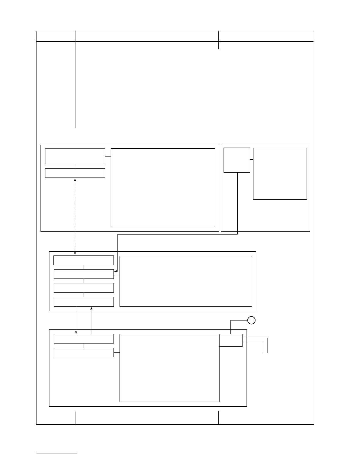
1. Operation control
Description
Receiving the user’s operation condition setup, the operation statuses of indoor/outdoor units are
controlled.
1) The operation conditions are selected by the remote controller or indoor unit display buttons as
shown in the bolow.
2) A signal is sent by ON button of the remote controller.
3) The signal is received by a sensor of the indoor unit and processed by the indoor controllers as
shown in the below.
4) The indoor controller controls the indoor fan motor and louver motor.
5) The indoor controller sends the operation command to the outdoor controller, and sends/receives
the control status with a serial signal.
6) The outdoor controller controls the operation as shown in the left, and also controls the compressor, outdoor fan motor, 4-way valve and pulse Modulating valve.
Indoor unit
Indoor unit control
• Command signal generating function of
indoor unit operation
• Calculation function (temperature calculation)
• Activation compensation function of indoor fan
• Cold draft preventive function
• Timer function
• Indoor heat exchanger release control
• Indoor fan motor
• Louver motor
Outdoor unit
Outdoor unit control
• Frequency control of inverter output
• Waveform composite function
• Calculation function
(Temperature calculation)
• AD conversion function
• Quick heating function
• Delay function of compressor reactivation
• Current release function
• GTr over-current preventive function
• Defrost operation function
• Compressor
• Outdoor fan motor
• 4-way valve
• Pulse Modulating valve
(P.M.V.)
Signal receiving
Indoor unit control
Operation command
Serial signal send/receive
Serial signal send/receive
Outdoor unit control
Inverter
~
Remote controller
Control contents of remote controller
• ON/OFF
• Operation select (COOL/HEAT/AUTO/DRY)
• Temperature setup
• Air direction
• Swing
• Air volume select
• ECO
• ON timer setup
• OFF timer setup
• Hi-POWER
Selection of
operation conditions
ON/OFF
(AUTO/LOW/LOW+/MED/MED+/HIGH)
• COMFORT SLEEP
• QUIET
• PRESET
• ONE-TOUCH
• FLOOR
Selecton
of
operation
conditions
Control contents of
unit display buttons
• ON/OFF
• Operation select
(AUTO/COOL/HEAT)
• Temperature setup
• Air outlet select
(AUTO/Upper/Lower
Indoor unit display buttons
FILE NO. SVM-18048
- 25 -
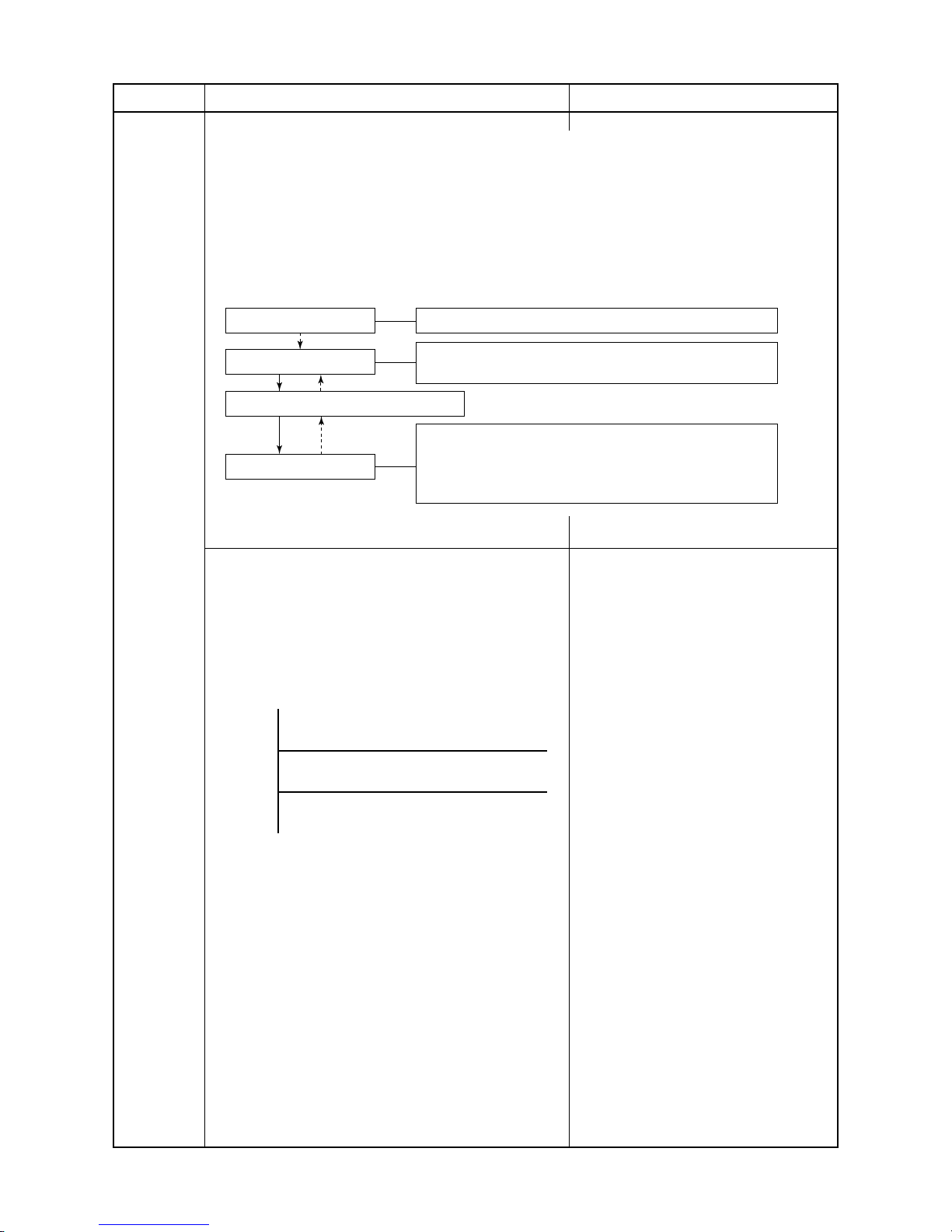
Operation ON
Setup of remote controller
Indoor fan motor control / Louver control / Operation Hz
Control (Requierment)
Indoor unit control
Sending of operation command signal
Outdoor unit control
[ ]
Compressor revolution control / Outdoor fan motor control /
4-way valve control In cooling operation: ON
In heating operation: OFF
Pulse Modulating valve control
Item
1. Basic
operation
Operation flow and applicable data, etc.
2. Cooling/Heating operation
Description
The operations are performed in the following parts by controls according to cooling/heating conditions.
1) Receiving the operation ON signal of the remote controller, the cooling or heating operation signal
starts being transferred form the indoor controller to the outdoor unit.
2) At the indoor unit side, the indoor fan is operated according to the contents of “2. Indoor fan
motor control” and the louver according to the contents of “9. Louver control”, respectively.
3) The outdoor unit controls the outdoor fan motor, compressor, pulse Modulating valve and
4-way valve according to the operation signal sent from the indoor unit.
3. AUTO operation
Selection of operation mode
As shown in the following figure, the operation starts by
selecting automatically the status of room temperature
(TA) when starting AUTO operation.
*1. When reselecting the operation mode, the fan
speed is controlled by the previous operation mode.
1) Detects the room temperature (TA) when
the operation started.
2) Selects an operation mode from TA in
the left figure.
3) Fan operation continues until an
operation mode is selected.
4) When AUTO operation has started
within 2 hours after heating operation
stopped and if the room temperature is
20°C or more, the fan operation is
performed with ”Super Ultra LOW” mode
for 3 minutes.
Then, select an operation mode.
5) If the status of compressor-OFF
continues for 15 minutes the room
temperature after selecting an operation
mode (COOL/HEAT), reselect an
operation mode.
Ts + 1
Ts – 1
Ta
Cooling operation
Monitoring (Fan)
Heating operation
Operation Hz control (Include limit control)
FILE NO. SVM-18048
- 26 -
1. Basic
operation
Operation flow and applicable data, etc.
Description
Item
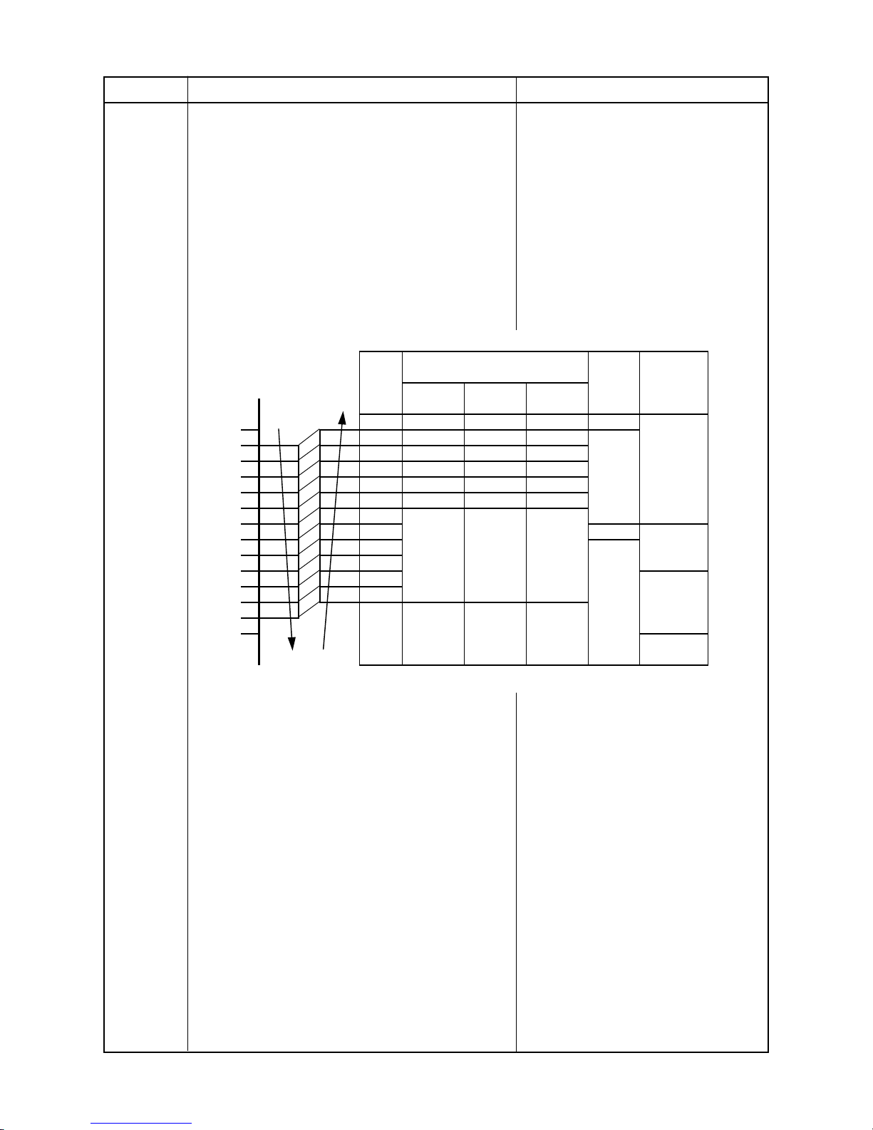
4. DRY operation
DRY operation is performed according to the
difference between room temperature and the setup
temperature as shown below.
In DRY operation, fan speed is controlled in order to
prevent lowering of the room temperature.
1) Detects the room temperature (TA) when
the DRY operation started.
2) Starts operation under conditions in the
left figure according to the temperature
difference between the room temperature and the setup temperature (Tsc).
Setup temperature (Tsc)
= Set temperature on remote controller
(Ts) + (-1.0 to 0.0)
3) When the room temperature is lower
2°C or less than the setup temperature,
turn off the compressor.
4) The time correction is performed every
8 minutes.
Fan Time
TA speed correction
(°C)
12 35 37 49 W8
11 32 34 42 W6
10 30 31 36
9272830
8252624
7222318
6202011
5W5
4W4
3
2
1
−1 zone
OFF OFF OFF (min 1)
+1 zone
±0
0
Compressor speed (rps)
B10U2FVG
Series
B13U2FVG
Series
B18U2FVG
Series
Zone
+4.5
+4.0
+3.5
+3.0
+2.5
+2.0
+1.5
+1.0
+0.5
0.0
−1.0
−1.5
−2.0
−0.5
FILE NO. SVM-18048
- 27 -
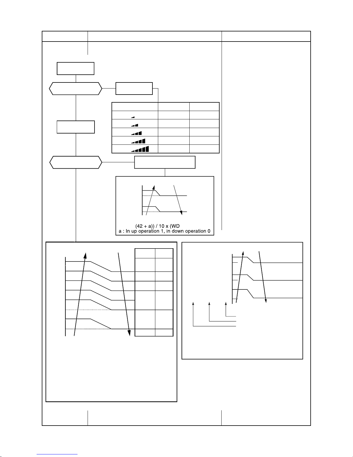
Item
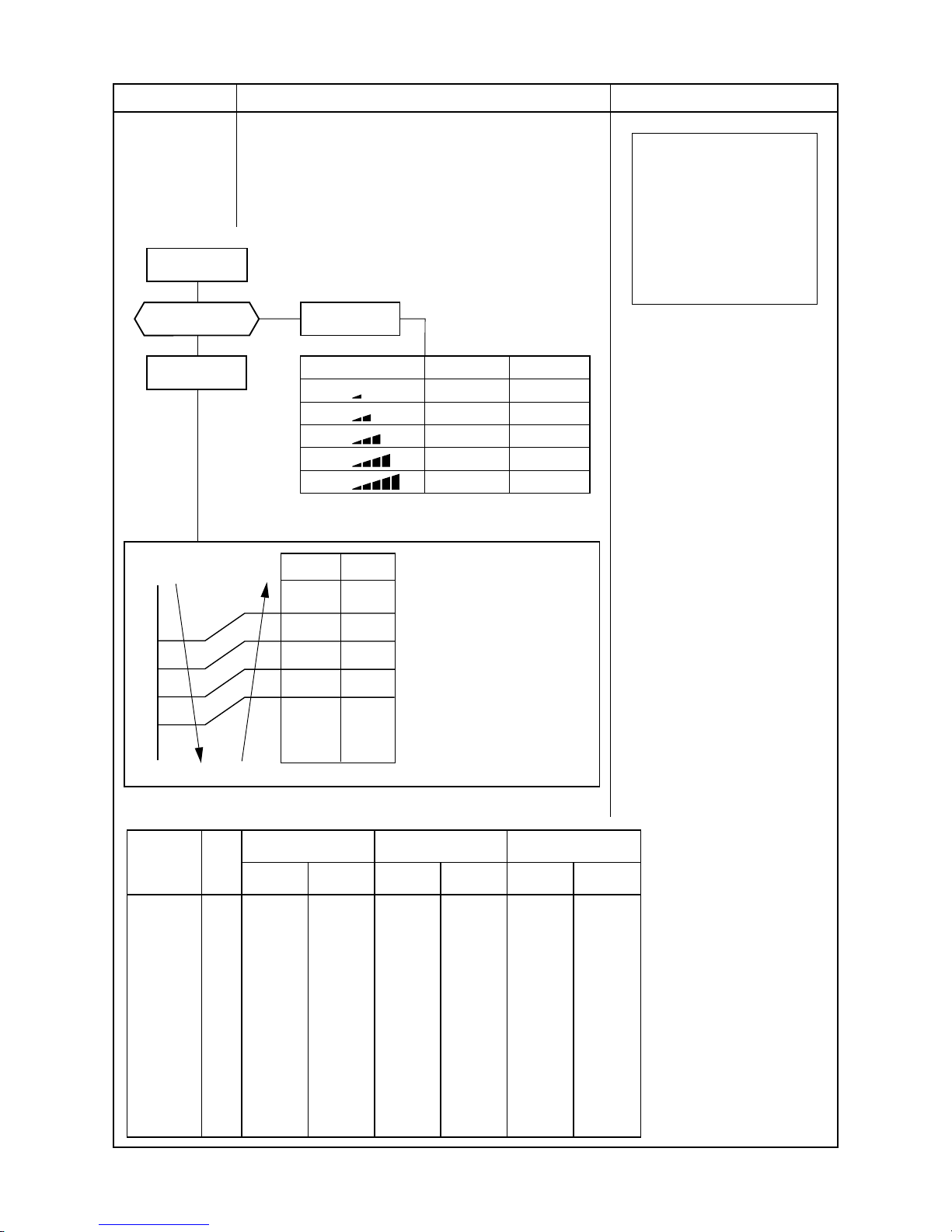
2. Indoor fan
motor control
Operation flow and applicable data, etc.
<In cooling operation>
(This operation controls the fan speed at indoor unit side.)
The indoor fan (cross flow fan) is operated by the phase-
control induction motor. The fan rotates in 5 stages in
MANUAL mode, and in 5 stages in AUTO mode, respectively. (Table 1)
Description
* Symbols
UH : Ultra High
H : High
M+ : Medium+
M : Medium
L+ : Low+
L: Low
L- : Low–
UL : Ultra Low
SUL : Super Ultra Low
* The fan speed broadly varies due
to position of the louver, etc.
The described value indicates one
under condition of inclining
downward blowing.
1) When setting the fan speed to L,
L+, M, M+ or H on the remote
controller, the operation is
performed with the constant
speed shown in Fig. 1.
2) When setting the fan speed to
AUTO on the remote controller,
revolution of the fan motor is
controlled to the fan speed level
shown in Fig. 2 and Table 1
according to the setup temperature, room temperature, and heat
exchanger temperature.
(Fig. 1)
(Fig. 2)
L
L+
M
M+
H
W7
(L + M) / 2
WA
(M + H) / 2
WD
Indication
Fan speed
Fan speed setup
COOL ON
AUTO
+2.5
TA-Tsc
[°C]
+2.0
+1.5
+1.0
+0.5
Tsc
a
b
c
d
e
M+(WC)
*3
*4
*5
L(W7)
MANUAL
*3 : Fan speed = (M + −L) x 3/4 + L
*4 : Fan speed = (M + −L) x 2/4 + L
*5 : Fan speed = (M + −L) x 1/4 + L
(Linear appro ximation
from M+ and L)
Hi Power
Fan speed
H+(WD)
*6
*7
*8
L+(W8)
*6 : Fan speed = (H −L+) x 3/4 + L+
*7 : Fan speed = (H −L+) x 2/4 + L+
*8 : Fan speed = (H −L+) x 1/4 + L+
(Linear appro ximation
from H and L+)
Hi-POWER
W8
(L + M) / 2
WC
(M + H) / 2
WE
Fan speed
level
Fan speed Air flow rate Fan speed Air flow rate Fan speed Air flow rate
(rpm) (m3/h) (rpm) (m3/h) (rpm) (m3/h)
WF 530 498 560 528 650 624
WE UH 530 498 560 528 650 624
WD H 500 468 540 510 630 600
WC M+
450 414 490 459
560 528
WB
450 414 490 459
560 528
WA M
400 366 440 408
500 468
W9
360 324 390 354
450 414
W8 L+
350 315 390 354
450 414
W7 L 300 258 340 300 400 366
W6
L−
260 216 270 228 360 324
W5 UL 260 216 270 228 340 300
W4 240 198 250 210 320 282
W3 SUL 240 198 240 198 300 258
W2 240 198 240 198 300 258
W1 240 198 240 198 300 258
RAS-B13U2FVG
Series
RAS-B18U2FVG
Series
Cool
RAS-B10U2FVG
Series
(table 1) Indoor fan air flow rate <Cooling>
FILE NO. SVM-18048
- 28 -
Item
2. Indoor fan
motor control
Operation flow and applicable data, etc.
<In heating operation>
Description
1) When setting the fan speed to L,
L+, M, M+ or H on the remote
controller, the operation is performed with the constant speed
shown in Fig. 3 and Table 1.
2) When setting the fan speed to
AUTO on the remote controller,
revolution of the fan motor is
controlled to the fan speed level
shown in Fig. 5 according to the set
temperature and room temperature.
3) Min air flow rate is controlled by
temperature of the indoor heat
exchanger (TC) as shown in Fig. 4.
4) Cold draft prevention, the fan
speed is controlled by temperature
of the indoor heat exchanger (TC)
as shown in Fig. 6.
(Fig. 3)
(Fig. 4)
Cold draft preventive control
(Fig. 6)
* No limitation while fan speed MANUAL mode is in stability.
* A: When Tsc ≥ 24, A is 24, and when Tsc < 24, A is Tsc
Tsc: Set value
H (WE)
Line-approximate
M+and SUL with TC.
SUL (W2)
Stop
46 46TC34
45 45 33
33 33 21
32 32 20
*A+4 *A+4 *A+4
*A-4 *A-4 *A-4
Fan speed MANUAL in starting
Fan speed AUTO in stability
Fan speed AUTO in star ting
Fan speed setup
HEAT ON
AUTO
YES
NO
MANUAL
TC ≥ 42 C
Min air flow rate control
Tc
52
51
42
41
Limited to Min WD tap
* Fan speed =
(TC –
– W8) + W8
No limit
*
Fan speed
Basic fan control
TSC
b
- 0.5
c
- 1.0
d
- 1.5
e
- 2.0
f
- 2.5
g
- 5.0
L+ (W9)
*1
*2
*3
M+(WD)
*1: Fan speed = (M + −L+) x 1/5 + L+
*2: Fan speed = (M + −L+) x 2/5 + L+
*3: Fan speed = (M + −L+) x 3/5 + L+
*4: Fan speed = (M + −L+) x 4/5 + L+
(Calculated with linear approximation from M+ and L+)
TA-Tsc [°C]
Hi Power
*4
H(WE)
M(W8)
*5
*6
*7
*8
- 5.5
*5: Fan speed = (H −M) x 1/5 + M
*6: Fan speed = (H −M) x 2/5 + M
*7: Fan speed = (H −M) x 3/5 + M
*8: Fan speed = (H −M) x 4/5 + M
(Calculated with linear approximation from H and M)
L
L+
M
M+
H
W8
(L + M) / 2
WB
(M + H) / 2
WE
Indication
Fan speed Hi-POWER
W9
(L + M) / 2
WD
(M + H) / 2
WF
(Fig. 5)
FILE NO. SVM-18048
- 29 -

(Table 2) Indoor fan air flow rate <Heating>
Fan speed
level
Fan speed Air flow rate Fan speed Air flow rate Fan speed Air flow rate
(rpm) (m3/h) (rpm) (m3/h) (rpm) (m3/h)
WF UH 560 528 600 570 690 666
WE H 540 510 580 552 670 642
WD M+
480 443
520 486
590
570
WC 440 408
470 435
570 540
WB M
430
399 460 426 520 486
WA 380 342
410 376
460 426
W9 L+
370 334 400 366
460 426
W8 L
320 282
340 300 400 366
W7 L- 260 216 270 228 360 324
W6 260 216 270 228 340 300
W5 UL 260 216 270 228 340 300
W4 260 216 270 228 340 300
W3 260 216 270 228 340 300
W2 SUL 240 198 250 210 320 282
W1 240 198 240 198 240 198
HEAT
Item
Operation flow and applicable data, etc. Description
[In starting and in stability]
FAN AUTO
FAN Manual
In starting
• Until 12 minutes passed after operation start
• When 12 to 25 minutes passed after operation
start and room temp. is 3°C or lower than set temp.
• Room temp. < Set temp. –4°C
In stability
• When 12 to 25 minutes passed after operation start
and room temp. is higher than (set temp. –3°C)
• When 25 minutes or more passed after operation start
• Room temp. = Set temp. –3.5°C
RAS-B13U2FVG
Series
RAS-B18U2FVG
Series
RAS-B10U2FVG
Series
FILE NO. SVM-18048
- 30 -

Item
3. Capacity
control
Operation flow and applicable data, etc.
The cooling or heating capacity depending on the load is
adjusted.
According to difference between the setup value of temperature and the room temperature, the capacity is adjusted by
the compressor revolution.
Description
1) The difference between set
temperature on remote controller
(Ts) and room temperature (TA)
is calculated.
2) According to the temperature
difference, the correction value of
Hz signal which determines the
compressor speed is set up.
3) The rotating position and speed
of the motor are detected by the
electromotive force occurred on
the motor winding with operation
of the compressor.
4) According to the difference
resulted from comparison of the
correction value of Hz signal with
the present operation Hz, the
inverter output and the commutation timing are varied.
5) Change the compressor motor
speed by outputting power to the
compressor.
* The contents of control
operation are same in cooling
operation and heating
operation
4. Current release
control
Set temp. (Ts)
Room temp. (TA)
Correction of Hz signal
Detection of electromotive force
of compressor motor winding
Detection of motor speed and rotor position
In
verter output change
Commutation timing change
Change of compressor speed
Remote controller Indoor unit
Ts –TA
Correction value of Hz signal ≤ Operating Hz
Please refer "Current release control" of outdoor unit
service manual.
5. De
frost control
(Only in heating
operation)
* Refer to the service manual of multi outdoor unit
to be combined.
FILE NO. SVM-18048
- 31 -

Item
6. Release protective
control by temperature of indoor heat
exchanger
Operation flow and applicable data, etc.
<In cooling/dry operation>
(Prevent-freezing control for indoor heat exchanger)
In cooling/dry operation, the sensor of indoor heat
exchanger detects evaporation temperature and
controls the compressor speed so that temperature of
the heat exchanger does not exceed the specified
value.
Description
1) When temperature of the indoor
heat exchanger drops below 5°C,
the compressor speed is
reduced. (P zone)
2) When temperature of the indoor
heat exchanger rises in the
range from 6°C to under 7°C, the
compressor speed is kept.
(Q zone)
3) When temperature of the indoor
heat exchanger rises to 7°C or
higher, the capacity control
operation returns to the usual
control in cooling operation.
(R zone)
1) When temperature of the indoor
heat exchanger rises in the
range from 50°C to 55°C, the
compressor speed is kept.
(Q zone)
When temperature of the indoor
heat exchanger drops in the
range from 46°C to under 55°C,
the compressor speed is kept.
(Q zone)
2) When temperature of the indoor
heat exchanger rises to 55°C or
higher, the compressor speed is
reduced. (P zone)
3) When temperature of the indoor
heat exchanger does not rise to
50°C, or when it drops below to
46°C, the capacity control
operation returns to the usual
control in heating operation.
(R zone)
<In heating operation>
(Prevent-overpressure control for refrigerating cycle)
In heating operation, the sensor of indoor heat ex-
changer detects condensation temperature and controls
the compressor speed so that temperature of the heat
exchanger does not exceed the specified value.
7 C
6 C
5 C
R
Q
P
55 C
52 C
48 C
P
Q
R
Usual cooling capacity control
Reduction of compressor speed
Indoor heat exchanger temperature
When the value is
in Q zone, the
compressor speed
is kept.
Reduction of compressor speed
Usual heating capacity control
Indoor heat exchanger temperature
When the value is
in Q zone, the
compressor speed
is kept.
FILE NO. SVM-18048
- 32 -

Item
7. Air outlet
Operation flow and applicable data,etc
Description
selection
< How to change air outlet selection >
1. Operate the air conditioner and select cooling or heating
mode.
(Air outlet selection can't be changed at standby mode.)
• In Cooling operation, only lower-flow
can't be selected.
2. Push AIR OUTLET SELECT button on the unit operation
panel to change air outlet selection.
1. Purpose
2. Description
• In Dry mode operation,bi-flow and
lower-flow can't be selected.
• In heating operation and bi-flow
setting, the air outlet is set only upper
flow for preventing cold draft when
the indoor heat exchanger sensor
temperature (TC) is lower than 33
degrees.
• In cooling operation and bi-flow
setting, the air outlet is set only upper
flow for pravinting the room from
overcooling when the room
temperature (TA) is nearing the setup
temperature.
This function can be cancelled to
AIR OUTLET SELECT button
AIR OUTLET indication
Air outlet is contorolled as below.
< How to cancel to change upper-flow at Bi-flow setting in cooling >
1. Stop operation.
2. Push and hold AIR OUTLET SELECT button on the unit
operation panel over 10seconds (less than 20seconds).
AIR OUTLET SELECT button
3. After holding 10seconds, 4 beep sounds in heard and
TEMPERATURE indicator displays "1" for 5seconds.
Release AIR OUTLET SELECT button.
change setting.
FILE NO. SVM-18048
- 33 -

Item
Operation flow and applicable data,etc
Description
7. Air outlet
selection
< How to set to change upper-flow at Bi-flow setting in
cooling
1. Stop operation.
2. Push and hold AIR OUTLET SELECT button on the unit
operation panel over 10seconds (less than 20seconds).
AIR OUTLET SELECT button
3. After holding 10seconds, 4 beep sounds in heard and
TEMPERATURE indicator displays "1" for 5seconds.
Release AIR OUTLET SELECT button.
8. Lower air
outlet louver
< How to open or close the lower louver at standby mode >
control
1. Push AIR OUTLET SELECT button on the unit operation
panel.
AIR OUTLET SELECT button
1. Purpose
When something is dropped to inside
of the unit from upper air outlet, this
function helps to remove something
from lower air outlet
2. When lower louver is closed, lower louver moves to open
position and TEMPERATURE indicator displays
"OP" (OPEN) during louver moving.
When lower louver is opened, lower louver moves to open
position and TEMPERATURE indicator displays "CL"
(CLOSE) during louver moving.
TMPERATURE indicator
<Close->Open> <Open->Close>
< Louver position in operation >
Lower louver is controlled in operation as below.
FILE NO. SVM-18048
- 34 -

Item
9. Upper air
Operation flow and applicable data,etc
Description
outlet louver
Upper louver position can be arbitrarily set pu by pushing
[FIX] button of the remote control.
1. Description
The position is controlled as below.
control
· Upper louver position is stored in
memory by the microcomputer, and
the louver returns to the stored
position when the next operation is
performed. (Cooling/heating memory
position)
FILE NO. SVM-18048
- 35 -

Item
10. ECO
operation
Operation flow and applicable data, etc.
When pressing [ECO] button on the remote controller, a
Economic operation is performed.
<Cooling operation>
This function operates the air conditioner with the difference
between the set and the room temperature as shown in the
following figure.
Description
<Heating operation>
<Heating operation>
1) Setting the compressor speed to
Max. aHz, the temperature zone
in which the operation can be
performed with Max. cHz is
gradually widened after 30
minutes passed when starting
ECO operation.
* 12 (DRY max - COOL min) /6 x 5 + COOL min
* 11 (DRY max - COOL min) /6 x 4 + COOL min
* 10 (DRY max - COOL min) /6 x 3 + COOL min
* 9 (DRY max - COOL min) /6 x 2 + COOL min
* 8 (DRY max - COOL min) /6 x 1 + COOL min
30 minutes
A
B
C
A
B
C
→ Time Compressor
speed
0Hz
A zone
aHz
B zone
a to cHz
C zone
cHz
0
–0.5
–1.0
–1.5
–2.0
–2.5
–3.0
–4.0
–5.0
–6.0
–7.0
–8.0
–9.0
–10.0
–11.0
(Room temp. – Set temp.)
+3.5
+3.0
+2.5
+1.5
+1.0
TSC
-1.0
-2.0
+5.5
1H 2H
11
10
7
6
5
4
3
2
1
OFF
Dry Max
*12
*11
*
9
*8
*10
+6.0
TA-Tsc
3H
4H
+5.0
+4.5
+4.0
+2.0
+0.5
-0.5
12
9
8
Time
Zone
Frequency
FAN
MinHz
Fan speed depend on presetting and can change every speed.
0
-1.5
Time
correction
+1
ZONE
±0
-1
ZONE
min 1
Hz
a 20
c
1) The control target temperature
increase 0.5ºC per hour up to 2ºC
starting from the set temperature
when ECONO has been received.
2) The indoor fan speed is depend
on presetting and can change
every speed after setting ECO
operation.
<Cooling operation>
2) The indoor fan speed is depend
on presetting and can change
every speed after setting ECO
operation.
3) The compressor speed is
controlled as shown in the left
figure.
4) The time correction is performed
every 8minutes.
50
20
50
15
68
Hz
Cool min 20
35
20
37
11
49
DRY max
RAS-B13U2FVG
Series
RAS-B18U2FVG
Series
RAS-B10U2FVG
Series
RAS-B13U2FVG
Series
RAS-B18U2FVG
Series
RAS-B10U2FVG
Series
FILE NO. SVM-18048
- 36 -

Item
11. Test
operation
Operation flow and applicable data, etc.
When keeping [OPERATION] button pressed for
10 seconds or more, the temporary [COOL] operation
is performed.
Description
1) When pressing [OPERATION] button, the
previous setting operation starts.
2) When keeping [OPERATION] button pressed
for 3 seconds or more, Pi, Pi, Pi sound is
heard and [AUTO RESTART] control is
changed.
3) When keeping [OPERATION] button pressed
for 10 seconds or more, “Pi” sound is
heard and the test [COOL]
operation starts.
4) If the filter lamp goes on, press [OPERTION]
button to go off the filter lamp, and then
press [OPERTION] button again.
5) To stop the test operation, press
the button again.
Filter lamp ON
Press [OPERATION] button.
Did you press [OPERATION] button
for 3 seconds or more?
Did you press [OPERATION] button
for 10 seconds or more?
Switch to [AUTO RESTART] control.
YES
YES
NO
NO
NO
YES
Previous setting operation
Test [COOL] Operation
12. Discharge temperature control
* Refer to the service manual of multi outdoor unit
to be combined.
FILE NO. SVM-18048
- 37 -

Item
Operation flow and applicable data, etc.
This function controls throttle amount of the
refrigerant in the refrigerating cycle.
According to operating status of the air conditioner,
this function also controls the open degree of valve
with an expansion valve with pulse Modulation.
Description
1) When starting the operation, move the
valve once until it fits to the stopper.
(Initialize)
In this time, “Click” sound may be
heard.
2) Adjust the open degree of valve by super
heat amount. (SH control)
3) If the discharge temperature was excessively up, adjust the open degree of valve
so that it is in the range of set temperature.
(Discharge temp. control)
4) When defrost operation is performed, the
open degree of valve is adjusted according to each setup conditions during
preparation for defrost and during defrost
operation (4-way valve is inversed.).
5) To turn off the compressor while the air
conditioner stops by control of the
thermostat or by remote controller, adjust
the open degree of valve to the setup
value before stop of the compressor.
* SH (Super Heat amount) =
TS (Temperature of suction pipe of the compressor) –
TC or TE (Heat exchanger temperature at evaporation side)
* PMV: Pulse Modulating Valve
Starting up
Defrost
Initialize
Move to
initial position
*PMV open degree control
*SH control
Td
release control
Stop by
remote controller
Power OFF
Room temp. sensor
(Ta sensor) control
Compressor ON
13. Pulse
Modu
lating
value (P.M.V.)
control
FILE NO. SVM-18048
- 38 -

Item
14. Self-Cleaning
Operation flow and applicable data, etc.
1. Purpose
The Self-Cleaning operation is to minimize the
growth of mold, bacteria etc. by running
the fan and drying so as to keep the
inside of the air conditioner clean.
Self-Cleaning operation
When the cooling or dry operation shuts
down, the unit automatically starts the SelfCleaning operation which is then performed
for the specified period based on duration
of the operation which was performed
prior to the shutdown, after which the
Self-Cleaning operation stops.
(The Self-Cleaning operation is not
performed after a heating operation.)
2. Operation
1) When the stop signal from the remote
controller or timer-off function is received,
only the timer indicator light.
2) The period of the Self-Cleaning operation
is determined by the duration of the
operation performed prior to the
reception of the stop code.
3) After the Self-Cleaning operation has
been performed for the specified period,
the unit stops operating.
Unit now performing cooling or dry operation
Press “STOP” button
Only timer indicator lights, and Self Cleaning operation starts
Time set now elapses
Operation stops
function
• During Self-Cleaning operations: The louver opens
slightly. The indoor fan operates continuously at
a speed of 240 rpm.
Cooling: Auto (cooling) Dry
Heating: Auto (heating)
Auto (fan only)
Shutdown
Operation time
Up to 10 minutes
No Self-Cleaning operation
performed (0 minutes)
10 minutes
30 mins.
or longer
No Self-Cleaning operation performed
• To stop an ongoing Self-Cleaning operation at any time
Press the start/stop button on the remote controller twice during the Self-Cleaning
operation. (After pressing the button for the first time, press it for the
Self-Cleaning operation times
second time without delay (within 10 minutes).)
Description
Self-Cleaning operation time
FILE NO. SVM-18048
- 39 -

Item
14. Self-Cleaning
function
Operation flow and applicable data, etc.
• Self-Cleaning diagram
Description
15. Self-Cleaning
function release
Operation display ON OFF OFF
FCU fan
ON ON
OFF
rpm is depend on presetting. (240RPM)
Upper airoutlet OPEN OPEN (11º) CLOSE
Timer display
ON or OFF
ON
ON or OFF
depend on presetting of timer function. depend on presetting of timer function.
Compressor
ON or OFF
OFF OFF
depend on presetting per room temperature.
CDU fan ON or OFF
OFF OFF
depend on presetting per room temperature.
Cool mode or dry mode
operation more than 10 mins.
Self-Cleaning mode
operate 30 mins.
Automatically turn-off.
Operation time
Turn off by remote controller or
timer-off function.
How to cencel Self-Cleaning function
To cancel the Self-Cleaning function, proceed as
follows:
Press and hold [MODE] button on opreation
panel for more than 10 seconds.
(less than 20 seconds)
Lower airoutlet
OPEN or CLOSE
OPEN or CLOSE
depend on airoutlet selection
depend on airoutlet selection
OPEN or CLOSE
depend on airoutlet selection
After holding about 10 seconds, the air conditioner
beep 4 times without any blinking of display.
After releasing [Mode] button, Self-Cleaning
function is cancelled.
How to set Self-Cleaning function
To set the Self-Cleaning function, proceed as
follows:
Press and hold [MODE] button on opreation
panel for more than 10 seconds.
(less than 20 seconds)
After releasing [Mode] button, Self-Cleaning
function is set.
After holding about 10 seconds, the air conditioner
beep 4 times and OPERATION display blinks
5 seconds.
FILE NO. SVM-18048
- 40 -

Item
16. Remote-A or B
selection
Operation flow and applicable data, etc.
Description
1. Purpose
This operation is to operate only one
indoor unit using one remote controller.
2. Description
When operating one indoor unit in a
situation where two indoor units have
been installed in the same room or
nearby rooms, this operation prevents the
remote controll signal from being
received simultaneously by both units,
thus preventing both units from operating.
3. Operation
The indoor unit on which the remote
controll selection has been set to B
receives the signal of the remote control
also set to B.
(At the factory the remote controller
selection is set to A on all the indoor
units. There is no A setting display.)
To separate using of remote control for each indoor
unit in case of 2 air conditioner are installed nearly.
Remote Control B Setup.
1. Push and hold button on the Remote
Control by the tip of the pencil.
Note : 1. Repeat above step to reset Remote Control
to be A.
2. Remote Control A has not "A" display.
3. Default setting of Remote Control from
factory is A.
FILE NO. SVM-18048
- 41 -
(Picture 2).
"00" will be shown on the display
(Picture 1
).
2. Press during pushing . "B" will show
on the display and "00" will disappear and the
air conditioner will turn OFF. The Remote
Control B is memorized
Unit B setup.
Press and hold MODE button for more than 20
seconds.
When A setup changed to B setup : 5 beeps will
sound and operation lamp blinks for 5 seconds.
When B setup changed to A setup : 5 beep will
sound.

Item
17. QUIET mode
Operation flow and applicable data, etc.
Description
When the [QUIET] button is pressed, the fan of the
indoor unit will be restricted the revolving speed at
−
until the [QUIET] button is pressed once
Remarks :
1. Quiet mode is unable to work in dry mode.
2. Quiet mode is appropriate to work with less
cooling load and less heating load condition.
Quiet mode is the system which, control the
revolving speed of indoor fan to work
constantly at lower than speed L. In addition,
noise level of indoor unit is less than usual.
speed L
again (cancel Quiet mode).
Because of the fan speed L- may cause not
enough the cooling capacity or heating
The principles of comfort sleep mode are:
• Quietness for more comfortable. When
• Save energy by changing room temperature
• The air condition can shut down by itself
Remarks:
1. Comfort sleep mode will not operate in dry
automatically.
mode.
automatically.
room temperature reach setting temperature
Cooling mode
• The preset temperature will increase as
show on ECO operation (Item No. 9)
• Press the [COMFORT SLEEP] button to
choose the operating hours. Repeat
pressing to select the hours.
• If the [COMFORT SLEEP] button is pressed
again means cancel comfort sleep mode.
Heating mode
• The preset temperature will drop down as
show on ECO operation (Item No. 9)
choose the operating hours. Repeat
• Press the [COMFORT SLEEP] button to
pressing to setect thehours.
• If the [COMFORT SLEEP] button is pressed
again means cancel comfort sleep mode.
(1hr, 3hr, 5hr or 9hr)
(1hr, 3hr, 5hr or 9 hr)
19. Short Timer
In the normal condition, after switching one circuit
breaker, 3-minutes delay time for compressor is
set for the maintenance of the un
it.
Purpose
To start the unit immediately for the purpose of
testing, trial...etc, short timer can be used.
maintenance of the unit.
Short Timer Setting
control without sending the signal to
[CHK] button and hold, "00" will show
to make "00" disappear.
setting on the remote operates
front panel turns ON continuously for
j
Press [ ] button to turn the unit OFF.
k Set the operation mode on the remote
the unit.
l Use the tip of the pencil to push the
on display, them press [SET] button
m
Press [ ] button to turn the unit ON.
n When short timer is activated, all
immediately, besides, all indicatiors on
3 seconds.
capacity.
18. COMFORT
SLEEP
FIX
PRESET
ONE-TOUCH
SWING
FLOOR
TIMER
ON
FILTER
CHK
CLOCK
OFF
SLEEP
SET
CLR
Hi-POWER ECO
QUIET
COMFORT
SLEEP
MODE
TEMP
FAN
l
m
FILE NO. SVM-18048
- 42 -

Item
Operation flow and applicable data, etc.
Description
0 12 25
*
AUTO/L L
Fan
Operation
Time after operation
starts (min)
One touch comfort is the fully automated operation
that is set according to the preferable condition in
a region.
21. Hi-POWER
([Hi-POWER] button on the remote controller
is pressed)
When [Hi-POWER] button is pressed while the indoor
unit is in Auto, Cooling or Heating operation, Hi-
20. One-Touch
Comfort
*AUTO/L: Fan operates depends on the setting
temperature and room temperature.
During the One Touch Comfort mode if the indoor
unit receives any signal with other operation mode,
the unit will cancel the comfort mode and operates
according to the signal received.
Operation condition for model to Europe
market
When an indoor unit receives "One Touch
Comfort Signal" from the remote controller,
the indoor unit operates as following.
1) Air conditioner starts to operation when
the signal is received, even if the air
conditioner was OFF.
2) Operation mode is set according to room
temperature, the same as AUTO mode.
3) Target temperature is 24ºC.
4) Louver position is set as stored position
of the operating mode.
5) Fan is controlled as followings.
Mode
POWER mark is indicated on the display of the remote
controller and the unit operates as follows.
1. Automatic operation
• The indoor unit operates in according to the
current operation.
2. Cooling operation
remote controller does not change.)
The indoor unit's fan speed level increase 1 tap
• The preset temperature drops 1ºC
(The value of the preset temperature on the
3. Heating operation
remote controller does not change.)
The indoor unit's fan speed level increase 1 tap
• The preset temperature increases 2ºC
(The value of the preset temperature on the
4. The Hi-POWER mode can not be set in Dry
operation
22. FILTER
When the elapsed time reaches 1000 hours after
Indicator
operation, the FILTER indicator lights.
After cleaning the filters, turn off the FILTER indicator.
How to Turn Off FILTER Indicator
Press [
OPERATION] button on the indoor unit.
FILE NO. SVM-18048
- 43 -

Item
Operation flow and applicable data,etc
Description
23. Set temp.
correction
Set temp. can be corrected by changing the set temp.
correnction value.
Initial setting of the set temp. correction value is 0.
For example, when set temp. is 25°C
but room temp. is stable 27°C at cooling
Set temp. = Set temp. (TS)+ Set temp. correction
Set temp. (TS) : remote control or indoor unit display setting
1. Purpose
temperature can be corrected.
• Continue to push and hold AIR
OUTLET SELECT button.
AIR OUTLET SELECT button
Set temp. correction
Cooling
(Dry mode)
Heating
−5 ∼ +5°C
−5 ∼ +5°C
3. Push OPERATION button on the unit operation panel
10 times.
When the difference between the set
temperature of the remote control and
the room temperature is wide due to
the installation condition, etc, the set
2. Description
< How to change the set temp. correction >
1. Operate the air conditioner and select cooling or heating
mode.
(The set temp. correction can't be changed at standby
mode.)
2. Push and hold AIR OUTLET SELECT button on the unit
operation panel
Set temp. correction value is displayed on the
TEMPERATURE indicator.
TEMPERATURE
OPERATION button
4. Push TEMPERATURE button (UP or DOWN) to change
set temp. correction.
TEMPERATURE button
5. Release AIR OUTLET SELECT button.
Set temp. correction is memorized and set temp. value is
displayed on the TEMPERATURE indicator again.
• Continue to push and hold AIROUTLET
SELECT button.
mode, chage set temp. correction
(Cooling) from 0 to − 2°C
FILE NO. SVM-18048
- 44 -

Item
24. Outdoor
Operation flow and applicable data,etc
Description
MODE
Heating
Cooling
Normal
(rps)
Normal
(rps)
Normal
(rps)
Normal
(rps)
Normal
(rps)
Normal
(rps)
*
*
*
*
*
*
*
*
*
*
*
*
Quiet
control
As shown in the table, the max. revolution number of
compressor can be reduced.
As the max. number of revolution of compressor is restricted.
the rise-up performance at the start time is weakened.
This function is disable with multi-outdoor unit connecting.
1. Purpose
noise.
• It can be change setting whether air
For the users who concern about
noise of the outdoor unit, this control
controls the max. revolution number
of the compressor to reduce the
2. Description
< How to set Outdoor Quiet control >
1. Push and hold OPERATION button for 20seconds.
• After pushing OPERATION button, air
conditioner starts operation.
(for only
1:1 outdoor
unit)
When air conditioner is on standby before setting.
conditioner is operationg or not.
OPERATION button
2. After holding 20seconds, beep sounds is heard and
OPERATION indicator flashes for 5seconds.
Release OPERATION button.
OPERATION indicator
3. Push OPERATION button to stop temporary operation.
(Set Auto restart function again)
< How to cancel Outdoor Quiet control >
1. Push and hold OPERATION button for 20seconds.
OPERATION button
2. After holding 20seconds, beep sounds is heard.
(OPERATION indicator doesn't flash).
Release OPERATION button.
3. Push OPERATION button to stop temporary operation.
(Set Auto restart function again)
• After pushing OPERATION button, air
conditioner starts operation.
• After 3seconds, 3 beeps are heard.
(Auto restart setting is changed.)
• After 10seconds, a beep is heard.
(Temporary operation starts and Auto
restart function is cancelled.)
• After 3seconds, 3 beeps are heard.
(Auto restart setting is changed.)
• After 10seconds, a beep is heard.
(Temporary operation starts and Auto
restart function is cancelled.)
B10U2FVG-E,-TR
B13U2FVG-E,-TR
B18U2FVG-E,-TR
* Refer to CDU service manual combined).
FILE NO. SVM-18048
- 45 -

Item
24. Outdoor
Operation flow and applicable data,etc
Description
Quiet
control
< How to set Outdoor Quiet control >
1. Push and hold OPERATION button for 20seconds.
• After pushing OPERATION button, air
conditioner starts operation.
(for only
1:1 outdoor
unit)
When air conditioner is in operation before setting.
OPERATION button
2. After holding 20seconds, beep sounds is heard and
OPERATION indicator flashes for 5seconds.
Release OPERATION button.
OPERATION indicator
< How to cancel Outdoor Quiet control >
1. Push and hold OPERATION button for 20seconds.
OPERATION button
2. After holding 20seconds, beep sounds is heard.
(OPERATION indicator doesn't flash).
Release OPERATION button.
• After pushing OPERATION button, air
conditioner stops operation.
• After 3seconds, 3 beeps are heard.
(Auto restart setting is changed.)
• After 3seconds, 3 beeps are heard.
(Auto restart setting is changed.)
FILE NO. SVM-18048
- 46 -

Operation
Press [OPERATION] button for more than
three seconds. (Less than 10 seconds)
Motions
The operation indicator is on.
The unit beeps three times The operation indicator flashes
and continues to operate. for 5 seconds.
If the unit is not required to operate at this time, press [OPERATION]
button once more or use the remote control to turn it off.
Operation
Press [OPERATION] button for more than
three seconds. (Less than 10 seconds)
Motions
The operation indicator is on.
The operation indicator is turned off.
The unit beeps three times. The operation indicator flashes
for 5 seconds.
If the unit is required to operate at this time, press [OPERATION] button
once more or use the remote control to turn it on.
9-3. Auto Restart Function
This indoor unit is equipped with an automatic restarting function which allows the unit to restart operating with
the set operating conditions in the event of a power supply being accidentally shut down.
The operation will resume without warning three minutes after power is restored.
This function is not set to work when shipped from the factory. Therefore it is necessary to set it to work.
9-3-1. How to Set the Auto Restart Function
To set the auto restart function, proceed as follows:
The power supply to the unit must be on ; the function will not set if the power is off.
Press the [OPERATION] button located in the display of the indoor unit continuously for three seconds.
The unit receives the signal and beeps three times.
The unit then restarts operating automatically in the event of power supply being accidentally shut down.
• When the unit is standby (Not operating)
• When the unit is in operation
• While the filter check indicator is on, OPERATION button has the function of filter reset betton.
FILE NO. SVM-18048
- 47 -
The unit is in operation.
↓
The unit stops operating.
↓ After approx. three seconds,
The unit is on standby.
↓
The unit starts to operate.
↓ After approx. three seconds,

Operation
Press [OPERATION] button for more than
three seconds. (Less than 10 seconds)
Motions
The operation indicator is on.
The unit beeps three times and continues to operate.
If the unit is not required to operate at this time, press [OPERATION]
button once more or use the remote control to turn it off.
Operation
Press [OPERATION] button for more than
three seconds. (Less than 10 seconds)
Motions
The operation indicator is on.
The operation indicator is turned off.
The unit beeps three times.
If the unit is required to operate at this time, press [OPERATION] button
once more or use the remote control to turn it on.
9-3-2. How to Cancel the Auto Restart Function
To cancel auto restart function, proceed as follows :
Repeat the setting procedure : the unit receives the signal and beeps three times.
The unit will be required to be turned on with the remote control after the main power supply is turned off.
• When the system is on stand-by (not operating)
• When the system is operating
9-3-3. Power Failure During Timer Operation
When the unit is turned off because of power failure
during timer operation, the timer operation is cancelled. In that case, set the timer operation again.
NOTE :
The Everyday Timer is reset while a command signal
can be received from the remote control even if it
stopped due to a power failure.
FILE NO. SVM-18048
- 48 -
The unit is in operation.
↓
The unit stops operating.
↓ After approx. three seconds,
The unit is on standby.
↓
The unit starts to operate.
↓ After approx. three seconds,

11
11
Infrared signal emitter
Start/Stop button
Mode select button (MODE)
Temperature button (TEMP)
Fan speed button (FAN)
Swing louver button (SWING)
Set louver button (FIX)
On timer button (ON)
Off timer button (OFF)
Sleep timer button (SLEEP)
Setup button (SET)
Clear button (CLR)
Memory and Preset button (PRESET)
One Touch button (ONE-TOUCH)
High power button (Hi-POWER)
Economy button (ECO)
Quiet button (QUIET)
Comfort sleep button (COMFORT SLEEP)
Filter reset button (FILTER)
Clock Reset button (CLOCK)
Check button (CHK)
Floor warming mode button (FLOOR)
1
2
9
9-4. Remote control
9-4-1. Remote control and its functions
18
3
4
5
6
7
8
10
19
11
20
12
13
14
15
16
17
18
19
19
9-4-2. Operation of remote control
1. ONE-TOUCH
Press the "ONE-TOUCH" button for fully automated operation that is customised to the typical consumer
preferences in your region of the world. The coutomised settings control temperature air flow strength, air flow
direction and other settings to provide you alternate contact with "ONE-TOUCH" of the button. If you
prefer other settings you can select from the many other operation functions of your Toshiba unit
Press ONE-TOUCH : Start the operaton.
, or
2. AUTOMATIC OPERATION
To automatically select cooling, heating operation.
1. Press MODE : Select A.
2. Press MODE : Select A.
3. COOLING / HEATING / FAN ONLY* OPERATION
1. Press MODE : Select Cool , Heat or Fan only .
2. Press MODE : Set the desired temperature.
Cooling : Min 17°C - Max 30°C. (Fan Only: No temperature indication)
3. Press FAN : Select AUTO, LOW , LOW+ , MED , MED+
HIGH .
20
22
21
* The remote controller that be had Fan only operation.
FILE NO. SVM-18048
- 49 -

Press HI-POWER : Start and stop the operation.
4. DRY OPERATION (COOLING ONLY)
For dehumidification, a moderate cooling performance is controlled automatically.
1. Press MODE : Select Dry .
2. Press MODE : Set the desired temperature.
5. Hi-POWER OPERATION
To automatically control room temperature and airflow for faster cooling or heating
operation (except in DRY and FAN ONLY mode)
Press ECO : Start and stop the operation.
8. TEMPORARY OPERATION
In case of the misplaced or discharged remote control
• Pressing the RESET button, the unit can start or stop
without using the remote control.
• Operation mode is set on AUTOMATIC
operation, preset temperature is 24°C
and fan operation is automatic speed.
9. TIMER OPERATION
Setting the ON Timer Setting the OFF Timer
Press
ON
: Set the desired ON timer.
Press
OFF
: Set the desired OFF timer.
Press
SET
: Set the timer. Press
SET
: Set the timer.
Press
CLR
: Cancel the timer. Press : Cancel the timer.
CLR
Press
ON
: Set the ON timer.
Press
SET
.
Press
OFF
: Set the OFF timer.
Press
SET
button during the ( or )
mark flashing.
1
1
2
3
2
3
3
4
Everyday timer allows the user to set both the ON & OFF timers and will be activated on a daily basis.
Setting Everyday Timer
· During the every day timer is activation, both arrows are indicated.
( or )
6. FLOOR WARMING OPERATION
Heating will operate with downward blowing only.
Temperature of air outlet will be higher than usual.
7. ECO OPERATION
To automatically control room temperature to save energy (except in DRY and FAN ONLY mode)
Note:
· Keep the remote control in accessible transmission to the indoor unit;
otherwise, the time lag of up to 15 minutes will occur.
· The setting will be saved for the next same operation.
Note: Dry Mode fan speed is set to Auto only.
Note: Cooling operation; the set temperature will increase automatically 0.5 degree/hour for 4 hours
(maximum 2 degrees increase).
Heating operation; the set temperature will decrease.
FILE NO. SVM-18048
- 50 -

10. PRESET OPERATION
Set your preferred operation for future use. The setting will be memorized by the
unit for future operation (except air flow direction).
1. Select your preferred operation.
2. Press and hold PRESET for 3 seconds to memorize the setting. The mark
P
displays.
3. Press PRESET : Operate the preset operation.
11. AUTO RESTART OPERATION
To automatically restart the conditioner after the power failure (Power of the unit
must be on.)
Setting
1. Press and hold the RESET button on the indoor unit for 3 seconds to set the
operation. (3 beep sound and OPERATION lamp blink 5 time/sec for 5 seconds)
• Do not operate ON timer and OFF timer.
2. Press and hold the RESET button on the indoor unit for 3 seconds to cancel the
operation. (3 beep sound but OPERATION lamp does not blink)
12. QUIET OPERATION
To operate at super low fan speed for quiet operation (except in DRY mode)
Press QUIET : Start and stop the operation.
Note: Under certain conditions, QUIET operation may not provide adequate
cooling or heating due to low sound features.
13. COMFORT SLEEP OPERATION
To save energy while sleeping, automatically control air flow and automatically turn OFF.
Press COMFORT SLEEP : Select 1, 3, 5 or 9 hrs for OFF timer operation.
14. SLEEP TIMER OPERATION
To start the sleep timer (OFF timer) operation
Press SLEEP : Select 1, 3, 5 or 9 hrs for OFF timer operation.
Press CLR to cancel the sleep timer operation.
15. FILTER RESET
Firstly, turn off the circuit breaker.
FILTER lamp lights on; the filter must be cleaned.
To turn off the lamp, push OPERATION button on the indoor unit or the FILTER.
button on the remote control.
Note: The filter indicator turns on after turns on after about 1000 hours.
• Clean the indoor unit and the remote control with a wet cloth when needed.
• No benzine, thinner, polishing powder or chemically-treated duster.
Indoor Unit and Remote Control
Note: Cooling operation; the set temperature will increase automatically 0.5 degree/hour for 4 hours
(maximum 2 degrees increase).
Heating operation; the set temperature will decrease.
• In case of timer are set, AUTO RESTART OPERATION does not activate.
FILE NO. SVM-18048
- 51 -

16. SELF CLEANING OPERATION (COOL AND DRY OPERATION ONLY)
Cleaning operation
This function is used to dry the inside of the air conditioner to reduce te growth of
mold, etc. indide the air conditioner.
• When the unit shuts down after having operated for 10 or more minutes in
the cooling or dry mode, the cleaning operation is started automatically, and
the TIMER indicator on the nuit's display panel turns on.
Cleaning operation duration
• The cleaning operation lasts for 30 minutes if the unit has been operating in
the cooling or dry mode for 10 minutes or more.
Note:
• SELF CLEANING operation is default setting from factory.
• How to cancel SELF CLEANING operation.
Press and hold MODE button on operation panel for more than 10 seconds
(less than 20 seconds). When canceling, 4 beeps sound.
• How to activate SELE CLEANING operation.
Press and hold MODE button on operation panel for more than 10 seconds
(less than 20 seconds). Then, 4 beeps will sound and operation lamp will
blink for 5 seconds.
17. OPERATION AND PERFORMANCE
1. Three-minute protection feature: To prevent the unit from being activated for
3 minutes when suddenly restarted or switched to ON.
2. Preheating operation: Warm up the unit for 5 minutes before blowing warm air.
3. Warm air control: When the room temperature reaches the set temperature,
the fan speed is automatically reduced and the outdoor unit will stop.
4. Automatic defrosting: Fans will stop during defrost operation.
5. Heating capacity: heat is absorbed from outdoor and released into the room.
When the outdoor temperature is too low, use another recommended heating
apparatus in combination with the air conditioner.
6. Consideration for accumulated snow: Select the position for outdoor unit when it
will not be subjected to snow drifts, accumulation of leaves or other seasonal debris.
7. Some minor cracking sound may occur when unit operating. This is normal because
the cracking sound may be caused by expansion/contraction of plastic.
Operation
Temp.
Outdoor Temperature
Room Temperature
Heating
Cooling
Dry
*
*
*
*
*
*
* Refer to the service manual of multi outdoor unit to be combined.
FILE NO. SVM-18048
- 52 -

18. TROUBLESHOOTING (CHECK POINT)
Unit B setup.
Press and hold MODE button for more than 20 seconds.
When A setup changed to B setup : 5 beeps will sound and operation lamp
• Check whether the operation mode is different from what has been selected
for the units in the other rooms (The following combinations of operations
In case of multiple connection
The unit does not operate. Cooling or Heating is abnormally low
• The power main switch is turned off.
• The circuit breader is activated to cut
off the power supply.
• Stoppage of electric current.
• ON timer is set.
• The filters are blocked with dust.
• The temperature has been set improperly.
• The windows or doors are opened.
• The air inlet or outlet of the outdoor unit
is blocked.
• The fan speed is too low.
• The operation mode is DRY.
Note: When there is an abnormality in the product, abnormal code (2 digits) will be
displayed on the unit display panel. Please contact the dealership.
cannot be performed: COOL and HEAT, DRY and HEAT).
• Select the same operation mode as for the other rooms.
19. REMOTE CONTROL A-B SELECTION
To separate using of remote control for each indoor unit in case of 2 air conditioners are installed nearly.
Remote Control B Setup.
1. Push and hold CHK · button on the Remote Control by the tip of the pencil.
"00" will be shown on the display
2. Press MODE : during pushing CHK ·. "B" will show on the display and "00" will disappear and the
air conditioner will turn OFF. The Remote Control B is memorized
Note: 1. Repeat above step to reset Remote Control to be A.
2. Remote Control A has not "A" display.
3. Default setting of Remote Control from factory is A.
blinks for 5 seconds.
When B setup changed to A setup : 5 beeps will sound.
20. ADJUSTING BRIGHTNESS OF UNIT DISPLAY PANEL
1. Press and hold AIR OUTLET SELECT button then press MODE button for 3 times (All lamp of the unit
display panel will be switched on).
(At that time, please press and hold the AIR OUTLET SELECT button)
2. Press and hold AIR OUTLET SELECT button on Unit display panel, then press TEMPERATION button
(Up), (Down) for select the desired brightness.
3. Brightness will be settled when AIR OUTLET SELECT button is released. Although the temperature
indicator is switched off, if press the temperature button (up) and (down), the set temperature will be
indicated, and then can adjust the temperature.
10 seconds after stopped pressing the button, the temperature indication will
be switched off.
FILE NO. SVM-18048
- 53 -
(Picture 2).
(Picture ).

4 stages of brightness can be changed.
Temperature indicator Other lamp
1
2
3
4
Usual
Darkness
Turn off
Turn off
Usual
Darkness
Turn off
Darkness
21. CHANGE AIR OUTLET GRILLE ON STABLE TIME (COOLING ONLY)
On cooling operation, whichever air outlet is set, only Upper is used when the room temperature
approaches the set temperature.
In case to keep up/down blowing, operate as below;
Press and hold AIR OUTLET SELECT button for more than 10 seconds (less than 20 seconds)
(4 beeps will sound then "1" indication at TEMPERATURE indicator will light up for 5 seconds).
For return to the former status, press and hold AIR OUTLET SELECT button for more than
4 seconds once again (In this time, 4 beeps will sound then "0" indication at TEMPERATURE
indicator will blinks for 5 seconds).
22. AIR INLET GRILLE MANTENANCE
Wash the air inlet grille with water using the soft sponge or towel.
• Dry it well in a shadow area after washing.
• Scour heavy dirt with neutral detergent for kitchen, and rinse it with the water
(Do not use the wire wool).
• Do not press the front panel strongly. It may be cracked.
FILE NO. SVM-18048
- 54 -

1
7
9
12
4
8
6
3
11
10
2
13
5
9-4-3. Name and Functions of Indications on Remote Controller
[Display]
All indications, except for the clock time indicator, are displayed by pressing the button.
1
Transmission mark
This transmission mark
indicates when the
remote controller transmits signals to the indoor
unit.
2
Mode indicator
Indicates the current operation mode.
(A : Auto changeover control,
: Cool, : Dry, : Heat)
3
Temperature indicator
Indicates the temperature setting.
(17°C to 30°C)
5
TIMER and clock time indicator
The time setting for timer operation or the clock
time is indicated.
The current time is always indicated except
during TIMER operation.
6
Hi-POWER indicator
Indicates when the Hi-POWER operation starts.
Press the Hi-POWER button to start and press it
again to stop the operation.
7
(PRESET) indicator
Flashes for 3 seconds when the PRESET button is
pressed during operation.
The
mark is shown when holding down the
button for more than 3 seconds while the mark is
flashing.
Press another button to turn off the mark.
8
ECO indicator
Indicates when the ECO is in activated.
Press the ECO button to start and press it again
to stop operation.
9
A, B change indicator remote controller
When the remote controller switching function is
set, “B” appears in the remote controller display.
(When the remote controller setting is “A”, there is
no indication at this position.)
10 Comfort
sleep
Indicates when comfort sleep is activaled.
Press comfort sleep button to selectter
11 Quiet
Indicates when quiet is activated.
Press quiet button to start and press it again to stop
operation.
12 One-Touch
Indicates when one touch comfort is activated.
Press one-touch button to start the operation.
13 Swing
Indicates when louver is swing.
Press swing button to start the swing operation
and press it again to stop the swing operation.
4
FAN speed indicator
Indicates the selected fan speed.
AUTO or five fan speed levels
(
LOW , LOW+ , MED , MED+ ,
HIGH ) can be shown.
Indicates AUTO when the operating mode
is : Dry.
FILE NO. SVM-18048
- 55 -

9-5. Indoor Unit Display & Unit Operation Panel
This indoor unit can be operated with the unit operation panel or using remote control.
Operational contents will be followed the one which was operated later.
If change the set temperature with operation panel of unit, temperature indication will be changed,
but the temperature display on the remote control will not change.
If set the air flow only with the upper port, a little air flow may happen at the lower port.
6
14
3
1
4
5
Remote control
light receiver
10
11
12
13
7
8
9
2
15
11
11
OPERATION button : Unit operation ON/OFF button, turn off FILTER CHECK indicator.
MODE button : Operation mode (Auto→Cooling→Heating→Aoto→ • • • )
AIR OUTLET SELECT button : Cooling, Auto (Upper & Lower→ Upper→ Upper & Lower→• • • )
3
1
2
∗ CHILD LOCK function : Press MODE button for 3 seconds. (It is possible to operate even when stopping.)
To cancel CHILD LOCK function, press MODE button for 3 seconds once again.
When CHILD LOCK function is activated, 3 beeps will sound.
When press MODE button to cancel the function, a beep will sound and then 3 seconds later 3 beep
sound may occur.
The indicator button will be invalid while the child lock function is activated.
(When press the button, 1 beep will sound).
Operation with remote control during the CHILD LOCK function works.
This function is cancelled when the power supply is off or failure.
Dry (upper only)
Heating (Upper & Lower→ Upper→ Upper & Lower→• • • )
On cooling operation, whichever air outlet is set, only Upper is used when the room temperature
approaches the set temperature.
During stop operation : Open/Close the lower air outlet grille.
When the TEMPERATURE indicator display "CL" the lower air outlet grille will be in closed status.
When the TEMPERATURE indicator display "OP" the lower air outlet grille will be in open status.
TEMPERATURE button (Up) : Setting temperature increase by 1°C
4
(17°C→18°C • • • 30°C )
TEMPERATURE button (Down) : Setting temperature decrease by 1°C
5
(30°C→ 29°C • • • 17°C )
COOL and DRY indicator (Blue)
6
HEAT indicator (Orange)
7
AUTO indicator (Green)
8
OPERATION indicator (Green)
9
HI-POWER indicator (Green)
10
FLOOR indicator (Orange)
TIMER indicator (Yellow)
FILTER CHECK indicator (Red)
11
12
13
TEMPERATURE indicator (Blue)
AIR OUTLET indicator (Green)
14
15
FILE NO. SVM-18048
- 56 -

10. INSTALLATION PROCEDURE
10-1. Installation Diagram of Indoor and Outdoor Units
1
Installation plate
50 mm or more
50 mm or more
Shield pipe
Air filter
5
Filter
5
Filter
70 mm or more
3
Batteries
7
Pan head
wood screw
4
Remote control holder
Do not allow the drain hose to get
slack.
Make sure to run the drain hose
sloped downward.
The auxiliary piping can be
connected to the left, rear left, rear
right, right, bottom right or bottom
left.
Cut the piping
hole sloped
slightly.
Right
Rear right
Left
Bottom right
Rear left
Bottom left
6
Mounting screw
8
Insulation sheet
2
Wireless remote control
8 mm thick heat resisting
polyethylene foam
Insulate the refrigerant pipes
separately with insulation, not together.
In case of right or left piping
cut dot-line area
A
C
L
• Loading Batteries
1. Remove the battery cover.
2. Insert 2 new batteries (AAA type)
following the (+) and (–) positions.
Before installing the wireless remote controller
3 Batteries
2 Wireless remote controller
FILE NO. SVM-18048
- 57 -

10-2. Optional Parts, Accessories and Tools
10-2-1. Optional Installation Parts
A
Parts name
Refrigerant piping
Liquid side : ∅6.35 mm
Gas side : ∅9.52 mm
Pipe insulating material
(polyethylene foam, 8 mm thick)
Putty, PVC tapes
Part
Code Q'ty
One
each
1
One
each
(RAS-B10,13U2FVG Series)
∅12.70 mm
(RAS-B18U2FVG Series)
B
C
FILE NO. SVM-18048
- 58 -

Part
No.
1
2
3
Part name (Q’ty)
Installation plate x 1
Wireless remote control x 1
Battery x 2
Part name (Q’ty)
Remote control holder x 1
Part
No.
4
5
6
Part
No.
Others
Name
Owner’s manual
Installation manual
Part name (Q’ty)
Insulation sheet x 1
Drain nipple*** x 1
10-2-2. Accessory and installation parts
10
AUTO
AUTO
FIX
PRESET
ONE-TOUCH
SWING
FLOOR
TIMER
ON
FILTER
CHK
CLOCK
OFF
SLEEP
SET
CLR
Hi-POWERECO
QUIET
COMFORT
SLEEP
MODE
TEMP
FAN
Mounting screw ∅ 4 x 25 l x 8
Flat head wood screw
∅
3.1 x 16 l x 2
Filter* x 2
9
8
7
Cap waterproof*** x 2
B Label x 2 (for Multi model)
11
* The part may differ from that shown.
** The number of parts may differ by model.
*** The part is packed with the outdoor unit.
FILE NO. SVM-18048
- 59 -

10-2-3. Installation/Servicing Tools
Changes in the product and components
In the case of an air conditioner using R32, in order to prevent any other refrigerant from being charged
accidentally, the service port diameter of the outdoor unit control valve (3 way valve) has been changed.
(1/2 UNF 20 threads per inch)
• In order to increase the pressure resisting strength of the refrigerant piping flare processing diameter and size
of opposite side of flare nuts has been changed. (for copper pipes with nominal dimensions 1/2 and 5/8)
New tools for R32(R410A)
New tools for
R32(R410A)
Gauge manifold
Charge hose
Electronic balance
for refrigerant charging
Torque wrench
(nominal diam. 1/2, 5/8)
Flare tool (clutch type)
Gauge for projection
adjustment
Vacuum pump adapter
Gas leakage detector
Applicable to R22 model
×
×
¡
×
¡
——
¡
×
Changes
As pressure is high, it is impossible to measure by means of
conventional gauge. In order to prevent any other refrigerant from
being charged, each port diameter has been changed.
In order to increase pressure resisting strength, hose materials
and port size have been changed (to 1/2 UNF 20 threads per inch).
When purchasing a charge hose, be sure to confirm the port size.
As pressure is high and gasification speed is fast, it is difficult to
read the indicated value by means of charging cylinder, as air
bubbles occur.
The size of opposite sides of flare nuts have been increased.
Incidentally,
a common wrench is used for nominal diameters 1/4 and 3/8.
By increasing the clamp bar’s receiving hole, strength of spring in
the tool has been improved.
Used when flare is made by using conventional flare tool.
Connected to conventional vacuum pump. It is necessary to use
an adapter to prevent vacuum pump oil from flowing back to the
charge hose. The charge hose connecting part has two ports-one
for conventional refrigerant (7/16 UNF 20 threads per inch) and
one for R32(R410A). If the vacuum pump oil (mineral) mixes with
R32(R410A) a sludge may occur and damage the equipment.
Exclusive for HFC refrigerant.
• Incidentally, the “refrigerant cylinder” comes with the refrigerant designation R32(R410A) and protector coating in
the U.S's ARI specified rose color (ARI color code: PMS 507).
• Also, the “charge port and packing for refrigerant cylinder” require 1/2 UNF 20 threads per inch corresponding to
the charge hose’s port size.
FILE NO. SVM-18048
- 60 -

7 m
60
9
0
7 m
7 m
45
45
60100
45
45
45
45
100 70
60
100
230
150
(700)
(600)
(205)
15
15
9
0
15
15
272
560
590
670
10-3. Indoor Unit
10-3-1. Installation Place
Remote control
• A place where there are no obstacles such as a curtain that may block the
signal from the remote control.
• Do not install the remote control in a place exposed to direct sunlight or
close to a heating source such as a stove.
• Keep the remote control at least 1 m apart from the nearest TV set or
stereo equipment (This is necessary to prevent image disturbances or
noise interference).
• The location of the remote control should be determined as shown below.
10-3-2. Cutting a Hole and Mounting
When the installation plate is directly mounted
on the wall
1. Securely fil t the installation plate onto the wall by screwing it in the upper
and lower parts to hook up the indoor unit.
2. To mount the installation plate on a concrete wall with anchor bolts, use
the anchor bolt holes as illustrated in the below fi gure.
3. Install the installation plate horizontally in the wall.
NOTE
• When drilling a wall that contains a metal lath, wire lath or metal plate, be
sure to use a pipe hole brim ring sold separately.
• A place which provides the spaces around the indoor unit as shown in the
diagram.
• A place where there are no obstacles near the air inlet and outlet.
• A place which allows easy installation of the piping to the outdoor unit.
• A place which allows the front panel to be opened.
• In case of block, brick, concrete or similar type walls, make ∅5 mm holes
in the wall.
• Insert clip anchors for appropriate mounting screws 6 .
Installation plate
(Keep horizontal direction)
ˇ 5 mm hole
Clip anchor
(local parts)
Anchor bolt
Projection
15 mm or less
Cutting a hole
Mounting the installation plate and screw position
• Direct sunlight to the indoor unit's wireless receiver should be avoided.
• The microprocessor in the indoor unit should not be too close to RF
noise sources.
(For details, see the owner's manual)
1. After determining the pipe hole position, drill the pipe hole (∅65 mm) at a
slight downward slant to the outdoor side.
6
Mounting
screw
∅4 mm x 25 l
Failure to fi rmly install the unit may result in personal injury and property
damage if the unit falls.
Remote
control
Indoor unit
Reception range
(Side view) (Top view)
Reception range
* : Axial distance
: Pipe hole (ˇ 65 mm)
(Side piping)(Rear piping)
(Bottom piping)
(Unit : mm)
Floor
Wall
Remote control
Installation Plate
CAUTIONCAUTION
CAUTION
FILE NO. SVM-18048
- 61 -

47
49
210
163
64
29
85
6 6
40
100
108
49
542 58
4085
112
148
R45
120
10-3-3. How to Install Indoor Unit
1. Remove the air inlet grille. Open the air inlet grille and remove the strap.
2. Remove the front panel (Remove the 4 screws).
NOTE
• The hole should be made at a slight downward slant on the outdoor side.
Shield pipe
Drain hose
Extension drain hose
Inside the room
2. Put water in the drain pan and make sure that the water is drained out of
doors.
3. When connecting extension drain hose, insulate the connecting part of
extension drain hose with shield pipe.
Arrange the drain pipe for proper drainage from the unit.
Improper drainage can result in dew-dropping.
Front panel
Air inlet grille
Hook
Treatment of piping connection
1) Check the fl are nut connections for the gas leak with a gas leak detector
or soap water.
2) To prevent gap in slit, fasten top and bottom with tape.
3) Slit is covered with tape.
4) Fasten with supplied Insulate sheet to prevent gap on the top of slit.
Gas leak check
Tape
Slit
8 Insulation sheet
Do not rise the
drain hose.
Do not form the
drain hose into
a wavy shape.
Do not put the
drain hose end
into water.
Do not put the
drain hose end in
the drainage ditch.
Drainage
1. Run the drain hose sloped downwards.
Wiring connection
Wiring of the connection cable is necessary to remove the front panel.
1. Remove the terminal cover and cord clamp.
2. Insert the connecting cable (according to the local rule) into the pipe hole
on the wall.
3. Take out the connecting cable through the cable slot on the rear panel so
that it protrudes about 50 cm from the front.
4. Insert the connecting cable fully into the terminal block and secure it
tightly with screws.
5. Tightening torque : 1.2 N·m (0.12 kgf·m)
6. Secure the connecting cable with the cord clamp.
7. Fix the terminal cover, install the front panel and grille inlet.
• Be sure to refer to the wiring system diagram labeled inside the front
panel.
• Check local electrical cords and also any specifi c wiring instructions or
limitations.
110 mm
20 mm
10 mm
50 mm
NOTE
• Use stranded wire only.
• Wire type : H07RN-F or 60245 IEC66 (1.0 mm2 or more)
Stripping length of the connecting cable
Terminal
block
Earth line
Screw
Cord clamp
Earth screw
Earth line
Screw
Terminal cover
Hook
Layout of connection piping
Connection piping
430 mm
Tape
CAUTION
CAUTION
FILE NO. SVM-18048
- 62 -

(700)
(600)
272
560
670
240 340
10-3-4. Concealed Installation
The special method to install the indoor unit bury in the wall is shown here.
Please make sure to change to wall burying mode.
1. To switch to the wall burying mode
To switch to the wall burying mode, press and hold AIR OUTLET
SELECT button for 20 seconds.
- When the operation set up and 5 beep sounds. Then indication at
Temperature indicator will light up for 5 seconds.
- To cancel, press AIR OUTLET SELECT button for 20 seconds then, 5
beep sounds. Then indication at Temperature indicator will blinks for 5
seconds.
- To prevent dewfall, above plate angle should be narrow.
3. Installation using the supporting plate
• To install into the existing wall hole, if it is impossible to keep 20-30 mm
of depth, use the supporting plate for securing the distance.
• Arrange the screw positions and supporting plate as shown in the
fi gure.
• Be sure to switch to wall burying mode.
(Rear screws potion)
(Field supply)
: Screw holes
(Field supply)
(Unit : mm)
Wall burying mode
For prevent dewfall
2. Wall hole size
Wall hole size should be enough to keep the distance with indoor unit as
shown in the following fi gure.
50 or more Indoor unit 50 or more
(Front view)
70 or more
800 or more
Wall
Floor
670 or more
2
0 to 30
240 to 250
Floor
Wall
(Side view)(Unit : mm)
4. In case of lattice establishment
• Follow the following fi gure, make sure to keep enough distance
between lattice, frame and wall.
• Be sure to switch to wall burying mode.
• The lattice should be make of wood.
• Between the air inlet and outlet, should be devided with partition board.
• Be sure to establish the open part for RECEIVER.
• The open part of lattice must be opens 70 % or more of the wall hole.
• The open part of lattice must be arranged uniformly.
(Top view)
Partition board
(Unit : mm)
(Side view)
NOTE
• In case the plinth is fi xed to the wall, please make sure to cut out the slit
on the left and right side of the main part.
Mounting directly on the floor
1) Fix the leg of indoor unit on the fl oor with 2 mounting screws.
2) Fix the upper part of indoor unit on the wall with 4 mounting screws.
Cut dot-line area
Slit
6 screw
(M4 x 25L)
Installation on the wall
1) Fix the installation plate on the wall with 4 mounting screws.
2) Hook the indoor unit on the installation plate.
3) Fix the upper part of indoor unit on the wall with 4 mounting screws.
(Floor installation)
Make sure to fi x it at a designated position with the screws.
Failure may result the damage of piping by the turning over of a set.
(Wall installation)
230
150
10
15
15
40
288
670
1000 mm or less
4 screw
(M4 x 25L)
4 screw
(M4 x 25L)
CAUTION
FILE NO. SVM-18048
- 63 -

500 140
(Side view)
Partition board
20 to 30
Opening for receiver
(Front view)
800 or more
670 or more
Partition board
Opening for receiver
50 or more
70 or more
50 or more
Remote control selector switch
• When two indoor units are installed in the same room or adjacent two
rooms, if operating a unit, two units may receive the remote control
signal simultaneously and operate. In this case, the operation can
be preserved by setting either one indoor unit or remote control to B
setting (Both are set to A setting in factory shipment).
• The remote control signal is not received when the settings of indoor
unit and remote control are different.
• There is no relation between A setting/B setting and A room/B room
when connecting the piping and cables.
When two indoor units are installed in the separated rooms, it is not
necessary to change the selector switches.
10-4-1. Setting
of Remote Control
Selector Switch
10-
4-2. Remote Control A-B Selection
To separate using of remote control for each indoor unit in case of 2 air
conditioners are installed nearly.
Remote Control B Setup.
1. Push and hold button on the Remote Control by the tip of the pencil.
"00" will be shown on the display
2. Press . "B" will show on the display and "00" will during pushing
disappear and the air conditioner will turn OFF. The Remote Control B
is memorized
Note : 1. Repeat above step to reset Remote Control to be A.
2. Remote Control A has not "A" display.
3. Default setting of Remote Control from factory is A.
Unit B setup.
Press and hold MODE button for more than 20 seconds.
When A setup changed to B setup : 5 beeps will sound and operation
lamp blinks for 5 seconds.
When B setup changed to A setup : 5 beep will sound.
10-4. OTHERS
10-
4-4. Auto Restart Setting
How to set the Auto Restart
1.
Press and hold
OPERATION
button on the indoor unit for 3 seconds to set
the operation (3 beep sound and OPERATION lamp blink 5 time/sec for 5
seconds).
2.
Press and hold
OPERATION
button on the indoor unit for 3 seconds to
cancel the operation (3 beep sound but OPERATION lamp does not blink).
•
In case of ON timer or OFF timer are set, it does not activate.
This product is designed so that, after a power failure, it can restart
automatically in the same operating mode as before the power failure.
10-
4-3. Test Operation
To switch the TEST RUN (COOL) mode, press OPERATION button for 10
seconds (The beeper will make a short beep).
Information
The product are shipped with Auto Restart function in the off position.
Turn it on as required.
(Picture 1
).
(Picture 2).
FILE NO. SVM-18048
- 64 -

11. HOW TO DIAGNOSE THE TROUBLE
The pulse motor circuits are mounted to both indoor and outdoor units. Therefore, diagnose troubles according
to the trouble diagnosis procedure as described below. (Refer to the check points in servicing written on the
wiring diagrams attached to the indoor/outdoor units.)
Table 11-1
No.
1
2
3
4
5
Troubleshooting Procedure
First Confirmation
Primary Judgment
Judgment by Flashing LED of Indoor Unit
Self-Diagnosis by Remote Controller
Judgment of Trouble by Every Symptom
No.
6
7
8
9
Troubleshooting Procedure
Check Code 1C and 1E
How to Diagnose Trouble in Outdoor Unit
How to Check Simply the Main Parts
How to Simply Judge Whether Outdoor
Fan Motor is Good or Bad
FILE NO. SVM-18048
- 65 -

11-1. First Confirmation
11-1-1. Confirmation of Power Supply
Confirm that the power breaker operates (ON) normally.
11-1-2. Confirmation of Power Voltage
Confirm that power voltage is AC 220–230–240 ± 10%.
If power voltage is not in this range, the unit may not operate normally.
11-1-3. Operation Which is not a Trouble (Program Operation)
For controlling the air conditioner, the program operations are built in the microcomputer as described in the
following table.
If a claim is made for running operation, check whether or not it meets to the contents in the following table.
When it does, we inform you that it is not trouble of equipment, but it is indispensable for controlling and main-
taining of air conditioner.
Table 11-1-1
No.
1
2
3
4
5
6
Operation of air conditioner
When power breaker is turned “ON”, the
operation indicator (Green) of the indoor
unit flashes.
Compressor may not operate even if the
room temperature is within range of
compressor-ON.
In Dry and ECO mode, FAN (air flow)
display does not change even though FAN
(air flow select) button is operated.
Increasing of compressor motor speed
stops approx. 30 seconds after operation
started, and then compressor motor speed
increases again approx. 30 seconds after.
In AUTO mode, the operation mode is
changed.
In HEAT mode, the compressor motor
speed does not increase up to the maximum speed or decreases before the
temperature arrives at the set temperature.
Description
The operation indicator of the indoor unit flashes when
power source is turned on. If [START/STOP] button is
operated once, flashing stops.
(Flashes also in power failure)
The compressor does not operate while compressor
restart delay timer (3-minutes timer) operates.
The same phenomenon is found after power source has
been turned on because 3-minutes timer operates.
The air flow indication is fixed to [AUTO].
For smooth operation of the compressor, the compressor motor speed is restricted to Max. 41 rps for 2 minutes, and Max.91 rps for 2 minutes to 3 minutes, respectively after the operation has started.
After selecting Cool or Heat mode, select an operation
mode again if the compressor keeps stop status for 15
minutes.
The compressor motor speed may decrease by hightemp. release control (Release protective operation by
temp.-up of the indoor heat exchanger) or current
release control.
FILE NO. SVM-18048
- 66 -

11-2. Primary Judgment
To diagnose the troubles, use the following methods.
1) Judgment by flashing LED of indoor unit
2) Self-diagnosis by service check remote controller
3) Judgment of trouble by every symptom
Firstly use the method 1) for diagnosis. Then, use the method 2) or 3) to diagnose the details of troubles.
11-3. Judgment by Flashing LED of Indoor Unit
While the indoor unit monitors the operation status of the air conditioner, if the protective circuit operates, the
contents of self-diagnosis are displayed with block on the indoor unit indication section.
Table 11-3-1
NOTES :
1. The contents of items B and C and a part of item E are displayed when air conditioner operates.
2. When item B and C, and item B and a part of item E occur concurrently, priority is given to the block of item B.
3. The check codes can be confirmed on the remote controller for servicing.
OPERATION (Green)
Flashing display (1 Hz)
OPERATION (Green)
TIMER (Yellow)
FILTER (Orange)
Flashing display (5 Hz)
OPERATION (Green)
FILTER (Orange)
Flashing display (5 Hz)
OPERATION (Green)
TIMER (Yellow)
Flashing display (5 Hz)
OPERATION (Green)
Flashing display (5 Hz)
Protective circuit operation for indoor P.C. board
Protective circuit operation for connecting cable
and serial signal system
Protective circuit operation for outdoor P.C. board
Protective circuit operation for others
(including compressor)
Power failure (when power is ON)
Indoor indication
lamp flashes.
Which lamp
does flash?
Item
A
B
C
D
E
Check
code
Block display Description for self-diagnosis
FILE NO. SVM-18048
- 67 -

11-4. Self-Diagnosis by Remote Controller (Check Code)
1. If the lamps are indicated as shown B to E in Table 11-3-1, execute the self-diagnosis by the remote controller.
2. When the remote controller is set to the service mode, the indoor controller diagnoses the operation condition and indicates the information of the self-diagnosis on the display of the remote controller with the check
codes. If a fault is detected, all lamps on the indoor unit will flash at 5Hz and it will beep for 10 seconds
(Beep, Beep, Beep ... ). The timer lamp usually flashes (5Hz) during self-diagnosis.
11-4-1. How to Use Remote Controller in Service Mode
TEMP
Press [CHECK] button with a tip of pencil to set the
remote controller to the service mode.
• “ ” is indicated on the display of the remote
controller.
Press [ON ] or [OFF ] button
If there is no fault with a code, the indoor unit will beep
once (Beep) and the display of the remote controller will
change as follows :
• The TIMER indicator of the indoor unit flashes continuously.
(5 times per 1 sec.)
• Check the unit with all 52 check codes ( to )
as shown in Table-11-4-1.
• Press [ON ] or [OFF ] button to change the check
code backward.
If there is a fault, the indoor unit will beep for 10
seconds (Beep, Beep, Beep...).
Note the check code on the display of the remote
controller.
• 2-digits alphanumeric will be indicated on the display.
• All indicators on the indoor unit will flash.
(5 times per 1 sec.)
1
2
3
4
Alphanumeric characters are
used for the check codes.
is 5. is 6.
is A. is B.
is C. is D.
• • •
Fig. 11-4-1
FIX
PRESET
ONE-TOUCH
SWING
FLOOR
TIMER
ON
FILTER
CHK
CLOCK
OFF
SLEEP
SET
CLR
Hi-POWER ECO
QUIET
COMFORT
SLEEP
MODE
TEMP
FAN
Press [ ] button to release the service mode.
• The display of the remote controller returns to as it
was before service mode was engaged.
Press [CLR] button. After service finish for clear
service code in memory.
• "7F" is indicated on the display of the remote
control.
FILE NO. SVM-18048
- 68 -

11-4-2 Caution at Servicing
1. After using the service mode of remote controller finished, press the [ ] button to reset the remote controller to
normal function.
2. After finished the diagnosis by the remote controller, turn OFF power supply and turn its ON again to reset the air
conditioner to normal operation. However, the check codes are not deleted from memory of the microcomputer.
3. After servicing finished, press [CLR] button of remote controller under service mode status to send code "7F" to the
indoor unit. The check code stored in memory is cleared.
Table 11-4-1
Block distinction Operation of diagnosis function
Check
code
Block
Check
code
Cause of operation
Air
conditioner
status
Display flashing
error
Indoor P.C. TA sensor ; The room Operation Flashes when 1. Check the sensor TA and connection.
board. temperature sensor is continues. error is detected. 2. In case of the sensor and its
short-Circuit or disconnection. connection is normal, check the
P.C. board.
TC sensor ; The heat Operation Flashes when 1. Check the sensor TC and connection.
exchanger temperature continues. error is detected. 2. In case of the sensor and its
sensor of the indoor unit connection is normal, check the
is out of place, disconnection, P.C. board.
short-circuit or migration.
Fan motor of the indoor unit All OFF Flashes when 1. Check the fan motor and connection.
is failure, lock-rotor, short- error is detected. 2. In case of the motor and its
circuit, disconnection, etc. connection is normal, check the
Or its circuit on P.C. board P.C. board.
has problem.
Other trouble on the indoor Depend on Depend on Replace P.C. board.
P.C. board. cause of cause of
failure. failure.
Action and Judgment
FILE NO. SVM-18048
- 69 -

Block distinction Operation of diagnosis function
Check
code
Block
Check
code
Cause of operation
Air
conditioner
status
Display flashing
error
Serial signal 1) Defective wiring of the Indoor unit Flashes when 1) to 3) The outdoor unit never
and connecting connecting cable or operates error is detected. operate.
cable. miss-wiring. continue. Flashing stop Check connecting cable and correct
2) Operation signal has not Outdoor unit and outdoor unit if defective wiring.
send from the indoor unit stop. start to operate Check 25A fuse of inverter P.C. board.
when operation start. when the return Check 3.15A fuse of inverter
3) Outdoor unit has not signal from the P.C. board.
send return signal to the outdoor unit is Check operation signal of the indoor
indoor unit when operation normal. unit by using diode. Measure voltage
started. at terminal block of the indoor unit
4) Return signal from the between No.2 and No.3 (or L2 and S)
outdoor unit is stop during If signal is varied 15-60V continuously,
operation. replace inverter P.C. board.
Some protector If signal is not varied, replace indoor
(hardware, if exist) of the P.C. board.
outdoor unit open 4) The outdoor unit abnormal stop at
circuit of signal. some time.
Signal circuit of indoor If the other check codes are found
P.C. board or outdoor concurrently, check them together.
P.C. board is failure Check protector (hardware) such
in some period. as Hi-Pressure switch,
Thermal-Relay, etc.
Check refrigerant amount or any
possibility case which may caused
high temperature or high pressure.
Check operation signal of the indoor
unit by using diode. Measure voltage
at terminal block of the indoor unit
between No.2 and No.3 (or L2 and S)
If signal is varied 15-60V continuously,
replace inverter P.C. board.
If signal is not varied, replace indoor
P.C. board.
Action and Judgment
* Signal send only 1 minute and stop. Because of return signal from outdoor unit has not received.
** Signal resend again after 3 minutes stop. And the signal will send continuously.
** * 1 minute after resending, the indoor unit display flashes error.
VDC
Time (Min)
0
34 78
15
60
Measured signal voltage by apply diode
3 minutes Delay, start
counting from power
supply ON or remote
OFF.
3 minutes stop
*
**
***
Sending signal of the indoor unit when have not return
signal from the outdoor unit.
Voltage variation stop
or have not voltage
output.
Note : Operation signal of the indoor unit shall be measured in the sending period as
picture below.
FILE NO. SVM-18048
- 70 -

Block distinction Operation of diagnosis function
Check
code
Block
Check
code
Cause of operation
Air
conditioner
status
Display flashing
error
Outdoor P.C. Current on inverter circuit All OFF Flashes after 1. Remove connecting lead wire of the
board is over limit in short time. error is detected compressor, and operate again.
Inverter P.C. board is 8 times*. 2. If outdoor fan does not operate or
failure, IGBT shortage, etc. operate but stop after some period,
Compressor current is replace the inverter P.C. board.
higher than limitation, 3. If outdoor fan operates normally,
lock rotor, etc. measure 3-Phase output of inverter
P.C. board (150-270VAC) at the
connecting lead wire of compressor.
4. If 3-Phase output is abnormal, replace
inverter P.C.Board.
5. If 3-Phase output is normal, replace
compressor. (lock rotor, etc.)
Compressor position-detect All OFF Flashes after 1. Remove connecting lead wire of the
circuit error or short-circuit error is detected compressor, and operate again.
between winding of 8 times*. 2. If outdoor fan does not operate or
compressor. operation but stop after some period,
replace the inverter P.C. board.
3. If outdoor fan operates normally,
measure resistance of compressor
winding. If circuit is shortage, replace
the compressor.
Current-detect circuit of All OFF Flashes after Even if trying to operate again, all
inverter P.C. board error. error is detected operations stop, replace inverter
4 times*. P.C. board.
All OFF Flashes after
error is detected
4 times*.
1. Check sensors, TE, TS connection. In
case of sensors and it’s connection is
normal, check the inverter P.C. board
2. Check 4way valve operation/position.
In case TE, TS detected temperature
relationship are different from normal
operation, “18” might be detected.
TE or TS sensor; abnormal.
Out of place, disconnection,
shortage, or misconnection
(TE sensor is connected to TS
connector, TS sensor is
connected to TE sensor
connector)
TE sensor; Outdoor heat
exchanger temperature sensor
TS sensor; Suction pipe
temperature sensor
TD sensor ; Discharge pipe All OFF Flashes after 1. Check sensors TD and connection.
temperature sensor is error is detected 2. In case of the sensor and its
disconnection or shortage. 4 times*. connection is normal, check the
inverter P.C. board.
Outdoor fan failure or its All OFF Flashes after 1. Check the motor, measure winding
drive-circuit on the inverter error is detected resistance, shortage or lock rotor.
P.C. board failure. 8 times*. 2. Check the inverter P.C. board.
TO sensor ; The outdoor Operation Record error 1. Check sensors TO and connection.
temperature sensor is
continues. after detected
2. In case of the sensor and its
disconnection or shortage.
4 times*.
connection is normal, check the
But does not
inverter P.C. board.
flash display.
Action and Judgment
FILE NO. SVM-18048
- 71 -

Block distinction Operation of diagnosis function
Check
code
Block
Check
code
Cause of operation
Air
conditioner
status
Display flashing
error
Compressor drive output error. All OFF Flashes after
(Relation of voltage, current error is detected
and frequency is abnormal) 8 times*.
Overloading operation of
compressor caused by
over-charge refrigerant,
P.M.V. failure, etc.
Compressor failure (High
current).
1. Check installation conditions such as
packed valve opening, refrigerant
amount and power supply (rate +10%,
both of operation and non operation
condition).
2. (In case of P.M.V. exists)
Check P.M.V. by measure the
resistance of the coil and confirm its
operation (sound of initial
operation, etc.)
3. Observe any possibility cause which
may affect operation load of
compressor.
4. Operate again. If compressor operation
is failure when 20 seconds passed
(count time from operation starting of
compressor), replace compressor.
* 4 or 8 times ; When first error is detected, error is count as 1 time, then once operation is stop and re-started.
After re-starting operation within 6 minutes, if same error is detected, error count is add (count become 2 times)
When error count comes 4, 8, 11 or 18 times, record error to check code. But after re-starting operation, if no
error is detected and air conditioner can operate more than 6 minutes, error count is cleared.
The others Return signal of the outdoor Indoor unit Flashes when
(including unit has been sent when operates error is detected.
compressor) operation start. But after continue. Flashing stop
that, signal is stop some time. Outdoor unit and outdoor unit
Instantaneous power stop. start to operate
failure. when the return
Some protector signal from the
(hardware) of the outdoor unit is
outdoor unit open normal.
circuit of signal.
Signal circuit of indoor
P.C. board or outdoor
P.C. board is failure
in some period.
1. Check power supply (Rate + 10%)
2. If the air conditioner repeat operates and
stop with interval of approx. 10 to 40
minutes.
(In case of these exist)
Check protector (hardware) such as
Hi-Pressure switch, Thermal-Relay, etc.
Check refrigerant amount, packed valve
opening and any possibility cause which
may affect high temperature or high
pressure.
3. Check operation signal of the indoor unit
by using diode. Measure voltage at
terminal block of the indoor unit
between No.2 and No.3 (or L2 and S) If
signal is varied 15-60V continuously,
replace inverter P.C. board.
If signal is not varied, replace indoor
P.C. board.
Action and Judgment
Outdoor P.C.
board
FILE NO. SVM-18048
- 72 -

Block distinction Operation of diagnosis function
Check
code
Block
Check
code
Cause of operation
Air
conditioner
status
Display
flashing error
Compressor does not rotate. All OFF Flashes after 1. Remove connecting lead wire of the
Because of missed wiring, error is detected compressor, and operate again.
missed phase or shortage. 8 times*. 2. If outdoor fan does not operate or
operation but stop after some period,
replace the inverter P.C. board.
3. If outdoor fan operates normally,
measure 3-Phase output of inverter
P.C. board (150-270VAC) at the
connecting lead wire of compressor.
4. If 3-Phase output is abnormal, replace
inverter P.C.Board.
5. If 3-Phase output is normal, measure
resistance of compressor winding.
6. If winding is shortage, replace the
compressor.
Discharge temperature All OFF Flashes after
exceeded 117
o
C.
error is detected
4 times*.
1. Check sensors TD.
2. Check refrigerant amount.
3. (In case of P.M.V. exists)
Check P.M.V. by measure the
resistance of the coil and confirm its
operation (sound of initial operation, etc.)
4. Observe any possibility cause which
may affect high temperature of
compressor.
Compressor is high current All OFF Flashes after
though operation Hz is error is detected
decreased to minimum limit. 8 times*.
Installation problem.
Instantaneous power
failure.
Refrigeration cycle
problem.
Compressor break down.
1. Check installation conditions such as
packed valve opening, refrigerant
amount and power supply (rate +10%,
both of operation and non operation
condition).
2. (In case of P.M.V. exists)
Check P.M.V. by measure the
resistance of the coil and confirm its
operation (sound of initial operation, etc.)
3. Observe any possibility cause which
may affect high current of compressor.
4. If 1, 2 and 3 are normal, replace
compressor.
Action and Judgment
Compressor failure (High
current).operation, etc.)
The others
(including
compressor)
FILE NO. SVM-18048
- 73 -

Block distinction Operation of diagnosis function
Check
code
Block
Check
code
Cause of operation
Air
conditioner
status
Display
flashing error
Action and Judgment
Indoor unit Flashes when 1.
. Check power supply (Rate +10%)
operates
error is detected
2.
continue.
Flashing stop
Return signal of the outdoor
unit has been sent when
operation start. But after
that, signal is stop some time.
Outdoor unit
and outdoor unit
stop.
start to operate
when the return
signal from the
outdoor unit is
normal.
. If the air conditioner repeat operat
and stop with interval of approx. 10 to
40 minutes.
(In case of these exist)
Check protector (hardware) such as
Hi-Pressure switch, Thermal-Relay,
etc.
Check refrigerant amount, packed
valve opening and any possibility
cause which may affect high
temperature or high pressure.
3. Check operation signal of the indoor
unit by using diode. Measure voltage
at terminal block of the indoor unit
between No.2 and No.3 (or L2 and S)
If signal is varied 15-60V continuously,
replace inverter P.C. board.
If signal is not varied, replace indoor
P.C. board.
4. Check and clean heat exchanger area
Indoor and Outdoor unit.
Instantaneous power
failure.
Some protector
(hardware) of the
outdoor unit open circuit
of signal.
Signal circuit of indoor
P.C. board or outdoor
P.C. board is failure in
some period.
TE, TC high tmperature
TE for cooling operation
TC for heating operation.
11 times*.
* 4
, 8
or 11 times ; When first error is detected, error is count as 1 time, then once operation is stop and re-started.
After re-starting operation within 6 minutes, if same error is detected, error count is add (count become 2
times)
When
error
count
comes
4,
8,
11
or
18
times,
record
error
to
check
code. But
after
re-starting
operation,
if no error is detected and air conditioner can operate more than 6 minutes, error count is cleared.
The others
(including
compressor)
(TE only exists in
the Heat Pump system)
5. Check sensors, TE, TS connection.
In case of sensors and it’s connection
is normal, check the inverter P.C. board.
6. Check 4way valve operation/position.
In case TE, TS detected temperature
relationship are different from normal
operation, “18” might be detected.
TE or TS sensor; abnormal.
Out of place, disconnection,
shortage, or misconnection
(TE sensor is connected to
TS connector, TS sensor is
connected to TE sensor
connector)
TE sensor; Outdoor heat
exchanger temperature
sensor
TS sensor; Suction pipe
temperature sensor
FILE NO. SVM-18048
- 74 -

11-5. Judgment of Trouble by Every Symptom
11-5-1. Indoor Unit (Including Remote Controller)
(1) Power is not turned on (Does not operate entirely)
<Primary check>
1. Is the supply voltage normal?
2. Is the normal voltage provided to the outdoor unit?
3. Is the crossover cable connected properly?
4. Is the fuse (F01) blown?
• Be sure to disconnect the motor connector CN301 after shut off the power supply, or it will be a cause of
damage of the motor.
(2) Power is not turned on though Indoor P.C. board is replaced
<Confirmation procedure>
NO
Turn off power supply once, and
5 second later, turn it on again.
Is OPERATION indicator flashing?
Is it possible to turn on
power supply by pushing
[ ] button
on remote controller?
Is voltage
(DC12V or 7V or 5V)
indicated on rear of
indoor control
board normal?
Does transmission mark
on remote controller flash
normally,and is its signal
transmitted properly?
Is DC310–340V
supplied between
CN301 1 – 3 ?
Does fan
motor connector
between CN301 1 –
3 short-circuit?
Item by symptoms
Operation
Check Item
Considerable principle cause
Measures
Parts (R01, R02, DB01, C01, C03
IC101 and T101) are defective.
Remote controller is defective.
Refer to (5) “Troubleshooting
for remote controller”.
Parts of a power supply circuit
defective.
Unit operates normally.
Replace main
P.C. board
Replace fan
motor.
Is fuse (F01)
of indoor control
board blown?
Microcomputer
is defective.
NO
NO
NO
NO NO
NO
YES
YES
YES
YES YES
YES YES
YES YES
NO
NO
To item of
“Power supply is not turned on”.
Turn on power supply.
Does OPERATION indicator flash?
Is wired correctly to white and
black lead wires of terminal block?
Correct wiring.
FILE NO. SVM-18048
- 75 -

(3) Only the indoor motor fan does not operate
<Primary check>
1. Is it possible to detect the power supply voltage (AC220–240V) between
L
and
N
on the terminal block?
2. Does the indoor fan motor operate in cooling operation?
(In heating operation, the indoor fan motor does not operate for approximately 10 minutes after it is turned
on, to prevent a cold air from blowing in.)
A
B
Start to operate
indoor unit in cooling
operation at airflow
level “LOW”.
Turn off indoor unit and
remove connector from motor.
Then start to operate indoor
unit with remote controller.
Turn off indoor unit and remove
connector from motor.
Then push [ ] button
on remote controller to stop
flashing lamp on indoor unit.
Change airflow level
to “HIGH”.
Start to operate the
indoor unit in except
heating operation.
At this time, is it possible
to detect DC 1V or more
between
5
+ and 3 –
of motor connector (CN301)?
(Check this condition
within 15 seconds after
starting unit.)
Start to operate the
indoor unit in except
heating operation.
At this time, is it possible to
detect DC 1V or more between
5
+ and 3 – of motor
connector (CN301)?
Is it possible to detect
DC 310–340V between
1
+ and 3 – of motor
connector (CN301).
(Motor connection condition)
Is it possible to detect DC 15V
between
4
+ and 3 – of
motor connector (CN301).
Is it possible to detect
DC 15V between
4
+
and
3
– of motor
connector (CN301).
Does indoor
fan operate?
Replace main
P.C. board.
YES
YES
YES
YES
YES
YES
NO
NO
NO
NO
NO
NO
Turn off power
supply once, and
turn it on again.
Is it possible to detect
DC 1V or more between
5
+ and
3
– of
motor connector (CN301)
.
Does fan motor
continue to operate?
Peplace indoor
fan motor.
YES
YES
NO
NO
Does check
operation LED flash?
Does check connecting
cable or power supply
cord complely?
Reconnecting the
interconnection cable
and terminal block
NO
NO
YES
Does check
5V at display unit?
Replace
display unit
Does check 5V
at main P.C board?
NO
NO
YES
YES
YES
FILE NO. SVM-18048
- 76 -

Turn off indoor unit
and rotate cross-flow
fan by hand when the
unit is on standby.
At this time, is it possible to
detect DC 1V or more
between 5 + and 3 –
of motor connector
(CN
301).
Is it possible to
change airflow level
to “HIGH”?
Is it possible to
rotate cross-flow fan by
hand properly?
Fan motor
operates normally.
Replace bearing
of cross-flow fan.
YES
YES
YES
NO
NO
NO
Does check cross-flow
fan bearing normal
condition?
Replace indoor
fan motor.
Replace main
P.C. board.
Does check display
on remote show high?
Change the new PC
board. Does fan speed
change?
Replace
remote
Replace
motor
NO
NO
NO
YES
YES
YES
A
B
FILE NO. SVM-18048
- 77 -

Indoor fan starts rotating when power supply is turned on.
(Check output DC voltage of fan motor on P.C. board.)
Measure voltage between 3 (GND : BLACK)
and 5 (V line : YELLOW) of motor connector (CN301)
while indoor fan motor is rotating.
DC 1.0V or more
P.C. board is defective.
6 (Blue)
5 (Yellow)
4 (White)
3 (Black)
2 –
1 (Red)
Motor is defective.
Under DC 1.0V
CN31
Yellow
Black
P.C. board
DC
Replace P.C. board. Replace motor.
(4) Indoor fan motor automatically starts to rotate by turning on power supply
<Cause>
The IC is built in the indoor fan motor. Therefore the P.C. board is also mounted to inside of the motor.
If the P.C. board is soldered imperfectly or the IC is defective, the fan motor may automatically rotate by turning
on power supply.
<Inspection procedure>
1. Remove the front panel. (Remove 4 screws.)
2. Remove the cover of the indoor unit controller. (remove 1 screw.)
3. Check DC voltage with CN301 connector while the fan motor is rotating.
NOTE :
• Do not disconnect the connector while the fan motor is rotating.
• Use a thin test rod.
FILE NO. SVM-18048
- 78 -

(5) Troubleshooting for remote control
<Primary check>
Check that A or B selected on the main unit is matched with A or B selected on the remote control.
FILE NO. SVM-18048
- 79 -
Push the [ ] button.
Does the transmission
indicator blink?
YES
YES
YES
YES
YES
YES
YES
Is there direct
sunlight on the
receptor of the air
conditioner?
Avoid direct
sunlight.
Is there any
thyristor
fluorescent light
nearly?
Keep the air
conditioner away
from thyristor
fluorescent light.
NO
NO
NO NO
NO
NO
NO
NO
Is operation possible
when setting the
temporary switch of the
air conditioner main unit
to “TEST RUN” or
“TEMPORARY AUTO”?
Can any signal tone
be heard in a transistor
radio when transmitting
within 5 cm distance
from the radio?
P.C. board is failure.
Replace
P.C. board
Is operation
possible when the
transmitter is moved
nearer to the infrared
signal receiver of the
air conditioner?
Battery life
Replace the
batteries
Dose the
transmission
indicator light?
Is there any
beep and
operation?
Normal
Remote control
is failure.
Replace remote
control.
Push the [ ]
button
YES
There is no beep from the indoor unit
The OPERATION lamp of the
air conditioner main unit does not light
Reset the remote
control by take off
batteries

Refer to the chart in 11-6.
Gas leak
P.M.V. is defective.
Miswiring of connecting wires of indoor/outdoor units
Clogging of pipe and coming-off of TC sensor
Gas circulation amount is down.
Measure gas pressure.
Gas shortage
Gas leak
Pipe clogging
Thermo. operation of compressor
Red
White
Terminal block
S5277G
Tester
3
2
1
Terminal block at indoor side
S5277G or equivalent (G or J type)
(Diode with rated voltage of 400V
or more is acceptable.)
To item of Outdoor unit does not operate.
11-5-2. Wiring Failure (Interconnecting and Serial Signal Wire)
(1) Outdoor unit does not operate
1) Is the voltage between R and S of the indoor terminal block varied?
Confirm that transmission from indoor unit to outdoor unit is correctly performed based upon the follow-
ing diagram.
NOTE:
• Measurement should be performed 2 minutes and 30 seconds after starting of the operation.
• Be sure to prepare a diode for judgment.
Normal time : Voltage swings between DC15 and 60V. ...................Inverter Assembly check (11-7-1.)
Abnormal time : Voltage does not vary.
(2) Outdoor unit stops in a little while after operation started
<Check procedure> Select phenomena described below.
1) The outdoor unit stops 10 to 20 minutes after operation started, and 10 minutes or more are required to
restart the unit.
2) If the unit stops once, it does not operate until the power will be turned on again.
3) The outdoor unit stops 10 minutes to 1 hour after operation started, and an alarm is displayed.
(Discharge temp. error check code 03, 1E Sensor temp. error check code 02, 1C)
FILE NO. SVM-18048
- 80 -

NO
NO
NO
NO
YES
YES
YES
YES
YES
Gas leakage,
disconnection of TS/TC
sensors (Check code 02, 1C)
Discharge temp. error,
gas leakage
(Check code 03, 1E)
1C 1E
Gas amount check and valve clogging check
Remove TC sensor connector from the P.C. board in indoor unit.
(Remove connector from the P.C. board.)
Operate the air conditioner in COOL mode by TEMP button
(“Beep” sound is heard if keeping pushed for 10 seconds.).
The operation enters temporary operation mode which fixes opening degree of compressor speed.
Check condensation at outlet of PMV, and then check operating pressure from the service port.
Valve drive check
Check the operating pressure from service port, and add gas if pressure is low.
Is connecter of coil connected to inverter?
Is coil of the pulse motor valve
(P.M.V.) correctly set?
Existence of condensation at outlet of P.M.V.
If there is condensation at outlet (1/4 inch=Ø6.35mm valve side),
the valve is clogged.
Are temp. sensors of indoor/outdoor units correctly set to the holder?
NOTE :
The temperature sensors which are used to control pulse motor valve
include indoor heat exchanger sensor (TC), outdoor heat exchanger temp.
sensor (TE), outdoor suction temp. sensor (TS) and outdoor sensor (TO).
Set it correctly.
Set it correctly.
Set it correctly.
Replace coil valve.
Replace valve.
Add gas.
Is positioning sound of valve (sound hitting to stopper) heard
from valve when the air conditioner starts the operation after turning off power
of the air conditioner once?
11-6. Check Code 1C (Miswiring in indoor/outdoor units) and 1E
<Check procedure>
FILE NO. SVM-18048
- 81 -

11-7. How to Diagnose Trouble in Outdoor Unit
Turn ON the unit
by remote controller
and wait for 3 min.
Check component
parts of control board
assembly by visual.
(damage, burn,.. Etc.)
Check Power Supply
(Voltage Rate ±10%)
Replace
fuse.
NG
OK
OK
YES
Turn OFF power
supply.
Check 25A
fuse (F01)
Remove connector
of compressor.
Replace
control board.
Check terminal
Voltage of electrolytic
capacitor are in
(Voltage Rate
Turn ON power
Supply.
NG
±10%) x 1.414?
Replace
control board.
NO
(Cooling : 17°C)
•
Connect discharge
resistance (approx. 100Ω,
40W) or soldering iron
(plug) between +, –
terminals of the electrol
ytic capacitor
(500µF or 760µF)
Discharging position
(Discharging period
10 seconds or more)
Plug of
soldering
iron
A
FILE NO. SVM-18048
- 82 -

YES
Does outdoor fan
operate normally?
Replace control
board.
YES
YES
Compressor
is normal
Check voltage of the
compressor connector
(AC150V-270V)?
Turn ON power
supply.
NO
Turn OFF power
supply.
Replace outdoor
fan motor.
NO
Replace
compressor.
Replace control
board.
Replace
compressor.
YES
Does compresser
operate normally?
Turn OFF power
supply.
Check compressor
winding resistance
correct?
is in rate.
A
NO
NO
YES
NO
Remove outdoor fan
connector.
Check winding resistance by
ohmmeter are correct?
Check rotor locking by rotate
with hand. Can it rotate?
FILE NO. SVM-18048
- 83 -

11-8. How to Check Simply the Main Parts
8-1. How to Check the P.C. Board (Indoor Unit)
(1) Operating precautions
1) When removing the front panel or the P.C. board, be sure to shut off the power supply breaker.
2) When removing the P.C. board, hold the edge of the P.C. board and do not apply force to the parts.
3) When connecting or disconnecting the connectors on the P.C. board, hold the whole housing. Do not pull
at the lead wire.
(2) Inspection procedures
1) When a P.C. board is judged to be defective, check for disconnection, burning, or discoloration of the
copper foil pattern or this P.C. board.
2) The P.C. board consists of the following 2 parts
a. Main P.C. board part :
DC power supply circuit, Indoor fan motor control circuit, CPU and peripheral circuits,
buzzer, and Driving circuit of louver.
b. Indication unit of infrared ray receiving infrared ray receiving circuit, LED :
To check defect of the P.C. board, follow the procedure described below.
FILE NO. SVM-18048
- 84 -

(3) Check procedures
1
2
3
4
5
6
7
Turn off the power supply breaker
and remove the P.C. board
assembly from electronic parts
base. Remove the connecting
cables from the terminal block.
Remove the connector of the
motor and turn on the power
supply breaker. If OPERATION
indicator flashes (once per
second), it is not necessary to
check steps (1 to 3) in the right
next column.
Push [ ] button once
to start the unit. (Do not set the
mode to On-Timer operation.)
Shorten the restart delay timer
and start unit.
Push [ ] button once
to start the unit,
• Shorten the restart delay timer.
• Set the operation mode to
COOL.
• Set the fan speed level to
AUTO.
• Set the preset temperature
much lower than the room
temperature. (The unit (compressor) operates continuously
in the above condition.)
If the above condition (No. 5) still
continues, start the unit in the
following condition.
• Set the operation mode to
HEAT.
• Set the preset temperature
much higher than room temperature.
Connect the motor connector to
the motor and turn on the power
supply.
Start the unit the following
condition.
• Set the fan speed level to HIGH.
(The unit (compressor) operates
continuously in the above
condition in No. 5.)
Check whether or not the fuse (F01)
is blown.
Check power supply voltage :
1. Between CN01 and No. 3 of CN301
(AC 220–240V)
2. Between and of C03
(DC 310–340V)
3. Between of IC122 and output
side of IC122 (DC15V)
Check power supply voltage :
1. Between CN01 and
CN501 (DC 15–60V)
Check whether or not all indicators
(OPERATION, TIMER, FILTER)
are lit for 3 seconds and they return
to normal 3 seconds later.
1. Check whether or not the compressor operates.
2. Check whether or not the OPERATION indicator flashes.
1. Check whether or not the compressor operates.
2. Check whether or not the OPERATION indicator flashes.
1. Check it is impossible to detect
the voltage (AC120V or higher
voltage) between red and black
2. The motor does not operate or
the fan motor does not rotate with
high speed.
(But it is possible to receive the
signal from the remote controller.)
3. The motor rotates but vibrates
Causes
Impulse voltage was applied or the
indoor fan motor short-circuited.
1. The terminal block or the crossover
cable is connected wrongly.
2. The fuse (F01), line filter
(L01), resistor (R02), of the diode
(DB01) is defective.
3. TC122 and T101 are defective.
4. D122, TC124 and T101 are defective
IC501 and IC502 are defective.
The indicators are defective or the
housing assembly (CN51) display PCB)
1. The temperature of the indoor heat
exchanger is extremely low.
2. The connection of the heat exchanger sensor is loose.
(The connector is disconnected.)
(CN602 and CN603)
3. The heat exchanger sensor and the
P.C. board are defective.
(Refer to Table 11-4-1.)
4. The main P.C. board is defective.
1. The temperature of the indoor heat
exchanger is extremely high.
2. The connection of the heat exchanger sensor short-circuited.
(CN602 and CN603)
3. The heat exchanger sensor and the
P.C. board are defective.
(Refer to Table 11-4-1.)
4. The main P.C. board is defective
1. The indoor fan motor is defective.
(Protected operation of P.C. board.)
2. The P.C. board is defective.
3. The connection of the motor
connector is loose.
lead of the motor.
strongly.
4. Between 12V and GND
5. Between 5V and GND
5. IC121,IC124, IC102,D121 and T101
are defective.
is defective.
Table 11-8-1
No. Procedure
Check points
FILE NO. SVM-18048
- 85 -

11-8-2. P .C . Board Layout
[1] Sensor characteristic table
100
30
40
50
60
70
80
90
20
10
0
0102030 4050
sResistance valueRe )
Temperature (°C)
TD : Discharge temp. sensor
TA : Room temp. sensor
TC and TCJ : Heat exchanger temp. sensor
TA,TC,TCJ
TD
FILE NO. SVM-18048
- 86 -

11-8-3. Indoor Unit (Other Parts)
No.
1
Part name
Room temp. (TA) sensor
Heat exchanger (TC) sensor
Checking procedure
Disconnect the connector and measure the resistance value with tester.
(Normal temp.)
Temperature
Sensor
TA, TC,TCJ (k. )
10°C20°C25°C30°C40°C
20.7 12.6 10.0 7.9 4.5
5
4
3
2
1
White
Yellow
Yellow
Yellow
Yellow
5
4
3
2
1
Refer to 11-5-1. (5).
Measure the resistance value of each winding coil by using the tester.
(Under normal temp. 25°C)
Position
1 to 2
1 to 3
1 to 4
1 to 5
Resistance value
250 ± 20.
Refer to 11-5-1. (3) and (4).
23Remote controller
Louver motor & Damper motor
MP24Z3N
4
Indoor fan motor
Heat exchanger (TCJ)sensor
ICF-340-41-1
FILE NO. SVM-18048
- 87 -

12. HOW TO REPLACE THE MAIN PARTS
WARNING
• Since high voltages pass through the electrical parts, turn off the power without fail before proceeding with
the repairs.
Electric shocks may occur if the power plug is not disconnected.
• After the repairs have been completed (after the front panel and cabinet have been installed), perform a
test run, and check for smoking, unusual sounds and other abnormalities.
If this check is omitted, a fire and/or electric shocks may occur.
Before proceeding with the test run, install the front panel and cabinet.
• Ensure that the following steps are taken when doing repairs on the refrigerating cycle.
1. Do not allow any naked flames in the surrounding area.
If a gas stove or other appliance is being used, extinguish the flames before proceeding.
If the flames are not extinguished, they may ignite any oil mixed with the refrigerant gas.
2. Do not use welding equipment in an airtight room.
Carbon monoxide poisoning may result if the room is not properly ventilated.
3. Do not bring welding equipment near flammable objects.
Flames from the equipment may cause the flammable objects to catch fire.
• If keeping the power on is absolutely unavoidable while doing a job such as inspecting the cir-
cuitry, wear rubber gloves to avoid contact with the live parts.
Electric shocks may be received if the live parts are touched.
High-voltage circuits are contained inside this unit.
Proceed very carefully when conducting checks since directly touching the parts on the control circuit
board may result in electric shocks.
No. Part name Procedure Remarks
① Front panel 1) Stop operation of the air conditioner
and turn off the main power supply.
2) Grip the air inlet grille by two hands
at the handle positions.
3) Pull the air inlet grille as the
arrow direction and remove the rope
from the hook of front panel.
4) Remove screws for front panel. (4 pcs)
Hook of front panel
Rope
Air inlet grille
4) Screws of front
panel (4 pcs)
FILE NO. SVM-18048
- 88 -

No. Part name Procedure Remarks
② Electrical parts 1) Remove screw for E-box cover.
Box assembly
(E-box)
2) Remove screw for drain guide. (4 pcs)
3) Remove screw for earth-lead.
4) Remove screw for display base.
5) Pull off the TC, TCJ sensor.
6) Take off fan motor conector.
7) Take off louver motor conector.
8) Take off damper motor conector.
9) Remove screw for earth-lead from fan
motor base.
10) Remove screw for E-box
11)
-
① Pull the upper part of the E-box.
11) - ② Lift a E-box in the upward for
take off from the hook.
1)Screw for E-box cover
Tube
TCJ sensor
TC sensor
5) TCJ sensor
5) TC sensor
4) The screw for
display base
2) Screws for
drain guide
(4 pcs)
3) Screw for
earth-lead
8) Damper motor connector
6) Fan motor connector
7) Louver motor connector
9) Screw for earth-lead from
fan motor base
10) Screw for E-box
Hook for locking E-box
①
②
FILE NO. SVM-18048
- 89 -

No. Part name Procedure Remarks
Damper motor lead
Display unit lead
Louver motor lead
Fan motor lead
Earth-lead from
fan motor base
Pipe holder
Screws for heat
exchanger (4 pcs)
② Electrical parts <How to arrange the lead>
Box assembly Shown in the picture.
(E-box)
③ Heat exchanger 1) Take off the pipe holder.
(Refrigerant
cycle assembly)
2) Remove screws for heat exchanger.
(4 pcs)
④
Horizontal 1) Open a horizontal louver outward and
louver stretch the arm of louver base same as
the direction in the picture.
FILE NO. SVM-18048
- 90 -

No. Part name Procedure Remarks
⑤ Louver base 1) Remove screws for louver base.
assembly (2 pcs)
2) - ① Pull the upper part of the louver
base to upward.
2) - ② Take off the louver base by pull
out in the front direction.
<Attention for louver base assemble>
Insert the rib of the louver base into the
slot of back body same as the picture.
⑥ Bell mouth
1) Remove screws for bell mouth. (4 pcs)
⑦ Drain pan and 1) Remove screws for drain pan. (2 pcs)
damper base
2) Remove screws for damper base.
(2 pcs)
①
②
Screws for louver base (2 pcs)
Louver base rib
Back body slot
Screws for bell mouth
(4 pcs)
Screw for drain pan
Screws for damper base
(2 pcs)
Screw for drain pan
FILE NO. SVM-18048
- 91 -

No. Part name Procedure Remarks
⑧ Turbo fan 1) Turn the flange nut (M10) in the
counter-clockwise direction and take it off.
2) Pull out the turbo fan from the fan
motor shaft.
<Attention for turbo fan assemble>
The tightening torque of the flange nut
is 5N·m.
⑨ Fan motor 1) Remove screws for motor holder,
and take off the motor holder.
2) Take off the lead cover.
<Attention for motor holder assemble>
1. Arrange the earth lead and fan
motor lead.
2. Adjust the motor axis to the center
of the motor holder then fix screws 4 pcs.
⑩ Fan motor A method to take off a fan motor in a
condition taking on a heat exchanger.
1) Take off pipe holder and remove
screws for heat exchanger. (refer to ③)
2) Remove screws for the bell mouth.
(refer to ⑥)
Screws for motor hold
(4 pcs)
Motor holder
Lead cover
FILE NO. SVM-18048
- 92 -

No. Part name Procedure Remarks
⑩ Fan motor 3) Remove the flange nut and turbo fan.
(refer to ⑧)
4) Remove screws for motor holder and
lead cover. (refer to ⑨
)
FILE NO. SVM-18048
- 93 -

No.
Part name
Common procedure
Procedure
1) Turn the power supply off to stop the
operation of air-conditioner.
2) Remove the front panel.
• Remove the 2 fixing screws.
3) Remove the electrical part base.
Remarks
Replace terminal block,
microcomputer ass’y and the
P.C. board ass’y.
12-2. Microcomputer
<P.C. board layout>
FILE NO. SVM-18048
- 94 -

13. EXPLODED VIEWS AND PARTS LIST
13-1. Indoor Unit
Location Part Location Part
No. No. No. No.
201 43T00553 212 43T19333
202 43T09460 213 43T79314
203 43T80325 214 43T79315
204 43T03379 215 43T49341
205 43T39340 216 43T72310
206 43T21424 217 43T70313
207 43T20330 218 43T22317
208 43T60408 219 43T22316
209 43T63331 220 43T22315
210 43T22314 221 43T63333
211
43T44632
222 43T62339
223 43T49340
211
43T44633
224 43T82316
225 43T66309
211
43T44634
226 43T83003
FRONT PANEL ASSY
INLET GRILLE ASSY
AIR FILTER
BACK BODY ASSY
MOTOR BASE ASSY
FAN MOTOR ASSY
TURBO FAN ASSY
MOTOR HOLDER
LEAD COVER
BELL MOUTH ASSY
REFRIGERANT CYCLE ASSY
(FOR RAS-B10U2FVG-E,-TR)
REFRIGERANT CYCLE ASSY
(FOR RAS-B13U2FVG-E,-TR)
REFRIGERANT CYCLE ASSY
(FOR RAS-B18U2FVG-E,-TR)
HOLDER, SENSOR
DRAIN GUIDE (UP)
DRAIN GUIDE (DOWN)
SHIELD PIPE
DRAIN PAN ASSY
HOSE, DRAIN
DAMPER ASSY
UPPER LOUVER ASSY
HORIZONTAL LOUVER
DISPLAY BASE
TERMINAL COVER ASSY
PIPE HOLDER
PLATE MOUNTING
WIRELESS REMOTE CONTROLLER
HOLDER, REMOTE CONTROL
SHEET-DISPLAY
Description Description
227 43T08425
FILE NO. SVM-18048
- 95 -

13-2. Indoor Unit (E-Part)
Location Part Location Part
No. No. No. No.
401 43T60406 406 43T69865
402 43T50321 407
43T6
V567
403 43T50332 407
43T6
V568
404 43T50333 407
43T6
V569
PC BOARD ASSY,WRS-LED
PC BOARD (FOR RAS-B10U2FVG-E,-TR)
PC BOARD (FOR RAS-B13U2FVG-E,-TR)
PC BOARD (FOR RAS-B18U2FVG-E,-TR)
405 43T62003
TERMINAL 3P
SENSOR;THERMOSTAT
SENSOR:HEAT EXCHANGER
SENSOR:HEAT EXCHANGER
CORD CLAMP
Description Description
FILE NO. SVM-18048
- 96 -

144/9 MOO 5, BANGKADI INDUSTRIAL PARK, TIVANON ROAD, TAMBOL BANGKADI,
AMPHUR MUANG, PATHUMTHANI 12000, THAILAND.
 Loading...