

Toshiba RAS-10G2KVP Series, RAS-13G2KVP Series, RAS-16G2AVP Series, RAS-16G2KVP Series, RAS-10G2AVP Series Installation Manual
...
Indoor unit
RAS-10G2KVP Series
RAS-13G2KVP Series
RAS-16G2KVP Series
Outdoor unit
RAS-10G2AVP Series
RAS-13G2AVP Series
RAS-16G2AVP Series
AIR CONDITIONER (SPLIT TYPE)
INSTALLATION MANUAL
1115751104
1115751104-EN.indd 11115751104-EN.indd 1 5/26/2557 BE 10:45 AM5/26/2557 BE 10:45 AM

PRECAUTIONS FOR SAFETY ...........................................................................................................................................1
INSTALLATION DIAGRAM OF INDOOR AND OUTDOOR UNITS ...................................................................................3
Optional Installation Parts ............................................................................................................................................... 3
INDOOR UNIT .....................................................................................................................................................................4
Installation Place .............................................................................................................................................................4
Cutting a Hole and Mounting Installation Plate ............................................................................................................... 4
Piping and Drain Hose Installation ..................................................................................................................................5
Indoor Unit Fixing ............................................................................................................................................................6
In case of Indoor unit is fi xed to Installation plate with screws ........................................................................................ 6
Drainage .........................................................................................................................................................................6
OUTDOOR UNIT .................................................................................................................................................................6
Installation Place .............................................................................................................................................................6
Refrigerant Piping Connection ........................................................................................................................................ 6
Evacuating .....................................................................................................................................................................7
ELECTRICAL WORKS .......................................................................................................................................................8
Wiring Connection ...........................................................................................................................................................8
Power Supply and Connecting Cable Connection .......................................................................................................... 9
Power supply input Wiring Diagram ..............................................................................................................................10
Wiring between DRED (Demand response enabling device) and Outdoor Unit ........................................................... 11
Connection procedure ...................................................................................................................................................11
Outdoor unit preparation ............................................................................................................................................... 12
OTHERS ............................................................................................................................................................................13
Gas Leak Test ...............................................................................................................................................................13
Remote Control A-B Selection ......................................................................................................................................13
Test Operation ..............................................................................................................................................................13
Auto Restart Setting .....................................................................................................................................................13
CONTENTS
EN
1115751104-EN.indd 21115751104-EN.indd 2 5/26/2557 BE 10:45 AM5/26/2557 BE 10:45 AM
EN
EN
FR
IT
DE
PT
PL
CZ
RU
CR
HU
TR
NL
GR
SV
FI
NO
DK
RO
BG
EE
LV
SK
SI
1
PRECAUTIONS FOR SAFETY
PRECAUTIONS FOR SAFETY
New refrigerant air conditioner installation
CAUTION
• THIS AIR CONDITIONER USES THE NEW HFC REFRIGERANT (R410A), WHICH DOES NOT DESTROY THE OZONE LAYER.
R410A refrigerant is apt to be affected by impurities such as water, oxidizing membranes, and oils because the pressure of R410A refrigerant is approx.
1.6 times of refrigerant R22. As well as the adoption of this new refrigerant, refrigerating machine oil has also been changed. Therefore, during installation
work, be sure that water, dust, former refrigerant, or refrigerating machine oil does not enter the refrigeration cycle of a new-refrigerant air conditioner.
To avoid mixing refrigerant and refrigerating machine oil, the sizes of charging port connecting sections on the main unit are different from those for the
conventional refrigerant, and different size tools are also required. For connecting pipes, use new and clean piping materials with high pressure withstand
capabilities, designed for R410A only, and ensure that water or dust does not enter. Moreover, do not use any existing piping as its pressure withstand
may be insuffi cient and may contain impurities.
DANGER
• FOR USE BY QUALIFIED PERSONS ONLY.
• MEANS FOR DISCONNECTION FROM THE SUPPLY HAVING A CONTACT SEPERATION OF AT LEAST 3 mm IN ALL POLES MUST BE
INCORPORATED IN THE FIXED WIRING.
• TURN OFF MAIN POWER SUPPLY BEFORE ATTEMPTING ANY ELECTRICAL WORK. MAKE SURE ALL POWER SWITCHES ARE OFF. FAILURE
TO DO SO MAY CAUSE ELECTRIC SHOCK.
• CONNECT THE CONNECTING CABLE CORRECTLY. IF THE CONNECTING CABLE IS CONNECTED WRONGLY, ELECTRIC PARTS MAY BE
DAMAGED.
• CHECK THE EARTH WIRE THAT IT IS NOT BROKEN OR DISCONNECTED BEFORE INSTALLATION.
• DO NOT INSTALL NEAR CONCENTRATIONS OF COMBUSTIBLE GAS OR GAS VAPORS. FAILURE TO FOLLOW THIS INSTRUCTION CAN
RESULT IN FIRE OR EXPLOSION.
• TO PREVENT OVERHEATING THE INDOOR UNIT AND CAUSING A FIRE HAZARD, PLACE THE UNIT WELL AWAY (MORE THAN 2 M) FROM
HEAT SOURCES SUCH AS RADIATORS, HEATERS, FURNACE, STOVES, ETC.
• WHEN MOVING THE AIR CONDITIONER FOR INSTALLING IT IN ANOTHER PLACE AGAIN, BE VERY CAREFUL NOT TO GET THE SPECIFIED
REFRIGERANT (R410A) WITH ANY OTHER GASEOUS BODY INTO THE REFRIGERATION CYCLE. IF AIR OR ANY OTHER GAS IS MIXED IN
THE REFRIGERANT, THE GAS PRESSURE IN THE REFRIGERATION CYCLE BECOMES ABNORMALLY HIGH AND IT RESULTINGLY CAUSES
BURST OF THE PIPE AND INJURIES ON PERSONS.
• IN THE EVENT THAT THE REFRIGERANT GAS LEAKS OUT OF THE PIPE DURING THE INSTALLATION WORK, IMMEDIATELY LET FRESH AIR
INTO THE ROOM. IF THE REFRIGERANT GAS IS HEATED BY FIRE OR SOMETHING ELSE, IT CAUSES GENERATION OF POISONOUS GAS.
• WHEN INSTALLING OR RE-INSTALLING THE AIR CONDITIONER, DO NOT INJECT AIR OR OTHER SUBSTANCES BESIDES THE DESIGNATED
REFRIGERANT “R410A” INTO THE REFRIGERATING CYCLE. IF AIR OR OTHER SUBSTANCES ARE MIXED, AN ABNORMAL PRESSURE CAN
OCCUR IN THE REFRIGERATING CYCLE, AND THIS CAN CAUSE AN INJURY DUE TO A PIPE RUPTURE.
For general public use
Power supply cord of parts of appliance shall be at least polychloroprene sheathed fl exible cord (design H07RN-F) or cord designation 60245 IEC66
(1.5 mm
2
or more). (Shall be installed in accordance with national wiring regulations.)
The manufacturer shall not assume any liability for the damage caused by not observing the description of this manual.
Be sure to read this installation manual carefully before installing.
Recommend to the owner to perform maintenance periodically when using over long periods of time.
Be sure to follow the precautions provided here to avoid safety risks. The symbols and their meanings are shown below.
DANGER : It indicates that incorrect use of this unit can result in a high possibility of severe injury (*1) or death.
WARNING : It indicates that incorrect use of this unit may cause severe injury or death.
CAUTION : It indicates that incorrect use of this unit may cause personal injury (*2), or property damage (*3).
*1 : A severe injury refers to blindness, injury, burns (hot or cold), electrical shock, bone fracture, or poisoning that leaves aftereffects and
requires hospitalization or extended out-patient treatment.
*2 : Personal injury means a slight accident, burn, or electrical shock which does not require admission or repeated hospital treatment.
*3 : Property damage means greater damage which affects assets or resources.
1115751104-EN.indd 11115751104-EN.indd 1 5/26/2557 BE 10:45 AM5/26/2557 BE 10:45 AM
2
WARNING
• Installation work must be requested from the supplying retail dealership. Self-installation may cause water leakage, electrical shock, or fi re as a result
of improper installation.
• Specifi ed tools and pipe parts for model R410A are required, and installation work must be done in accordance with the manual. HFC type refrigerant
R410A has 1.6 times more pressure than that of conventional refrigerant (R22). Use the specifi ed pipe parts, and ensure correct installation, otherwise
damage and/or injury may be caused. At the same time, water leakage, electrical shock, and fi re may occur.
• Be sure to install the unit in a place which can suffi ciently bear its weight. If the load bearing of the unit is not enough, or installation of the unit is
improper, the unit may fall and result in injury.
• Electrical work must be performed by a qualifi ed supplying retail dealership in accordance with the code governing such installation work, internal
wiring regulations, and the manual. A dedicated circuit and the rated voltage must be used. Insuffi cient power supply or improper installation may
cause electrical shock or fi re.
• Use a cabtyre cable to connect wires in the indoor/outdoor units. Midway connection, stranded wire, and single-wire connections are not allowed.
Improper connection or fi xing may cause a fi re.
• Wiring between the indoor unit and outdoor units must be well shaped so that the cover can be fi rmly placed. Improper cover installation may cause
increased heat, fi re, or electrical shock at the terminal area.
• Be sure to use only approved accessories or the specifi ed parts. Failure to do so may cause the unit to fall, water leakage, fi re or electrical shock.
• After the installation work, ensure that there is no leakage of refrigerant gas. If the refrigerant gas leaks out of the pipe into the room and is heated by
fi re or something else from a fan heater, stove or gas range, it causes generation of poisonous gas.
• Make sure the equipment is properly earthed. Do not connect the earth wire to a gas pipe, water pipe, lightning conductor, or telephone earth wire.
Improper earth work may be the cause of electrical shock.
• Do not install the unit where fl ammable gas may leak. If there is any gas leakage or accumulation around the unit, it can cause a fi re.
• Do not select a location for installation where there may be excessive water or humidity, such as a bathroom. Deterioration of insulation may cause
electrical shock or fi re.
• Installation work must be performed following the instructions in this installation manual. Improper installation may cause water leakage, electrical
shock or fi re. Check the following items before operating the unit.
- Be sure that the pipe connection is well placed and there are no leaks.
- Check that the service valve is open. If the service valve is closed, it may cause overpressure and result in compressor damage. At the same time, if
there is a leak in the connection part, it may cause air suction and overpressure, resulting burst or injury.
• In pump down operations, ensure to perform the following procedures.
- Do not inject air into the refrigeration cycle.
- Be sure to close both service valves and stop the compressor before removing the refrigerant pipe. If removing the refrigerant pipe while the
compressor is operating with the service valves opened, it may cause to air absorbed and abnormal high pressure inside the refrigeration cycle and
resulting burst or injury.
• Do not modify the power cable, connect the cable midway, or use a multiple outlet extension cable. Doing so may cause contact failure, insulation
failure, or excess current, resulting in fi re or electrical shock.
• Do not use any refrigerant different from the one specifi ed for complement or replacement. Otherwise, abnormally high pressure may be generated in
the refrigeration cycle, which may result in a failure or explosion of the product or an injury to your body.
• Be sure to comply with local regulations/codes when running the wire from the outdoor unit to the indoor unit. (Size of wire and wiring method etc.)
• Places where iron or other metal dust is present. If iron or other metal dust adheres to or collects on the interior of the air conditioner, it may
spontaneously combust and start a fi re.
• If you detect any damage, do not install the unit. Contact your supplying dealer immediately.
• Never modify this unit by removing any of the safety guards.
• Do not install in a place which cannot bear the weight of the unit. Personal injury and property damage can result if the unit falls.
CAUTION
• Please read this installation manual carefully before installing the unit. It contains further important instructions for proper installation.
• Exposure of unit to water or other moisture before installation could result in electric shock. Do not store it in a wet basement or expose to rain or water.
• After unpacking the unit, examine it carefully for possible damage.
• Do not install in a place that can increase the vibration of the unit. Do not install in a place that can amplify the noise level of the unit or where noise and
discharged air might disturb neighbors.
• This appliance must be connected to the main power supply by means of a circuit breaker depending on the place where the unit is installed. Failure to do
so may cause electrical shock.
• Follow the instructions in this installation manual to arrange the drain pipe for proper drainage from the unit. Ensure that drained water is discharged.
Improper drainage can result in water leakage, causing water damage to furniture.
• Tighten the fl are nut with a torque wrench using the prescribed method. Do not apply excess torque. Otherwise, the nut may crack after a long period of
usage and it may cause the leakage of refrigerant.
• Wear gloves (heavy gloves such as cotton gloves) for installation work. Failure to do so may cause personal injury when handling parts with sharp edges.
• Do not touch the air intake section or the aluminum fi ns of the outdoor unit. It may cause injury.
• Do not install the outdoor unit in a place which can be a nest for small animals. Small animals could enter and contact internal electrical parts, causing a
failure or fi re.
• Request the user to keep the place around the unit tidy and clean.
• Make sure to conduct a trial operation after the installation work, and explain how to use and maintain the unit to the customer in accordance with the
manual. Ask the customer to keep the operation manual along with the installation manual.
REQUIREMENT OF REPORT TO THE LOCAL POWER SUPPLIER
Please make absolutely sure that the installation of this appliance is reported to the local power supplier before installation. If you experience any problems
or if the installation is not accepted by the supplier, the service agency will take adequate countermeasures.
1115751104-EN.indd 21115751104-EN.indd 2 5/26/2557 BE 10:45 AM5/26/2557 BE 10:45 AM
EN
EN
FR
IT
DE
PT
PL
CZ
RU
CR
HU
TR
NL
GR
SV
FI
NO
DK
RO
BG
EE
LV
SK
SI
3
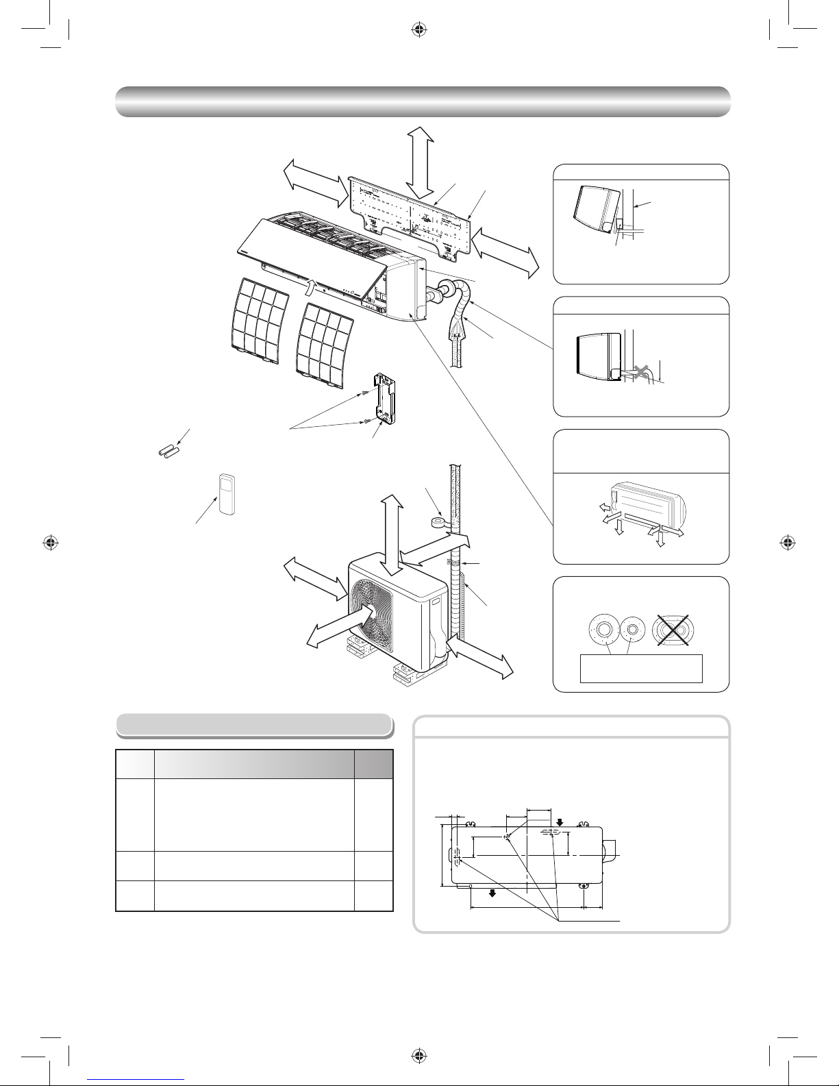
• Secure the outdoor unit with fi xing bolts and nuts if the unit is likely to be
exposed to a strong wind.
• Use Ø8 mm or Ø10 mm anchor bolts and nuts.
• If it is necessary to drain the defrost water, attach drain nipple 7 and cap
water proof 8 to the bottom plate of the outdoor unit before installing it.
Fixing bolt arrangement of outdoor unit
INSTALLATION DIAGRAM OF INDOOR AND OUTDOOR UNITS
INSTALLATION DIAGRAM OF INDOOR AND OUTDOOR UNITS
Part
code
Parts name Q’ty
A
Refrigerant piping
Liquid side : Ø6.35 mm
Gas side : Ø9.52 mm
(RAS-10, 13G2KVP Series)
: Ø12.7 mm
(RAS-16G2KVP Series)
One
each
B
Pipe insulating material
(polyethylene foam, 6 mm thick)
1
C
Putty, PVC tapes
One
each
Optional Installation Parts
Insulate the refrigerant pipes separately
with insulation, not together.
2
3
6
4
Insert the cushion between the indoor
unit and wall, and tilt the indoor unit for
better operation.
For the rear left and left piping
Wall
Make sure to run the drain hose sloped
downward.
Do not allow the drain hose to get slack.
Cut the piping
hole sloped
slightly.
The auxiliary piping can be connected to
the left, rear left, rear right, right, bottom
right or bottom left.
Right
Rear
right
Bottom
right
Rear
left
Bottom left
Left
1
Batteries
Flat head
wood screw
Remote control holder
Vinyl tape
Apply after carrying
out a drainage test.
Wireless remote control
Saddle
Extension
drain hose
(Not available,
provided by installer)
Shield pipe
(Attach to the front panel.)
Air fi lter
Hook
Installation
plate
Hook
52 mm or more
190 mm or more
225 mm or more
600 mm or more
100 mm or more
100 mm or more
600 mm or more
600 mm or more
Remark :
• Detail of accessory and installation parts can
see in the accessory sheet.
• Some pictures might be different from the
actual parts.
Drain outlet
Air inlet
Air outlet
125 mm
108 mm
Ø25 mm
29 mm
330 mm
106 mm
121 mm
99 mm600 mm
* Drain nipple and
cap water proof are
packed in outdoor
unit.
6 mm thick heat resisting
polyethylene foam
Bush body
1115751104-EN.indd 31115751104-EN.indd 3 5/26/2557 BE 10:45 AM5/26/2557 BE 10:45 AM

4
5
45º
45º
75º
Installation plate
(Keep horizontal direction.)
Anchor bolt
Projection
15 mm or less
5 mm dia. hole
Mounting screw
Ø4 x 25R
Clip anchor
(local parts)
INDOOR UNIT
INDOOR UNIT
Installation Place
• Direct sunlight to the indoor unit’s wireless receiver should be avoided.
• The microprocessor in the indoor unit should not be too close to RF
noise sources.
(For details, see the owner’s manual.)
Remote control
• A place where there are no obstacles such as a curtain that may block the
signal from the indoor unit
• Do not install the remote control in a place exposed to direct sunlight or close
to a heating source such as a stove.
• Keep the remote control at least 1 m apart from the nearest TV set or stereo
equipment. (This is necessary to prevent image disturbances or noise
interference.)
• The location of the remote control should be determined as shown below.
Cutting a Hole and Mounting
Installation Plate
NOTE
• When drilling a wall that contains a metal lath, wire lath or metal plate, be sure
to use a pipe hole brim ring sold separately.
Cutting a hole
When installing the refrigerant pipes from the rear
Mounting the installation plate
When the installation plate is directly mounted
on the wall
1. Securely fi t the installation plate onto the wall by screwing it in the upper and
lower parts to hook up the indoor unit.
2. To mount the installation plate on a concrete wall with anchor bolts, use the
anchor bolt holes as illustrated in the below fi gure.
3. Install the installation plate horizontally in the wall.
When installing the installation plate with a mounting screw, do not use the
anchor bolt holes. Otherwise, the unit may fall down and result in personal
injury and property damage.
1. After determining the pipe hole position on the mounting plate (¨), drill the
pipe hole (Ø65 mm) at a slight downward slant to the outdoor side.
• A place which provides the spaces around the indoor unit as shown in the
diagram
• A place where there are no obstacles near the air inlet and outlet
• A place which allows easy installation of the piping to the outdoor unit
• A place which allows the front panel to be opened
• The indoor unit shall be installed as top of the indoor unit comes to at least
2 m height. Also, it must be avoided to put anything on the top of the indoor
unit.
CAUTION
CAUTION
Failure to fi rmly install the unit may result in personal injury and property
damage if the unit falls.
• In case of block, brick, concrete or similar type walls, make 5 mm dia. holes
in the wall.
• Insert clip anchors for appropriate mounting screws 5.
NOTE
• Secure four corners and lower parts of the installation plate with 4 to 6
mounting screws to install it.
CAUTION
(Side view) (Top view)
Indoor unit
Reception range
Remote
control
Remote
control
Reception
range
Indoor unit
The center of the pipe
hole is above the arrow.
35
Ø
65
1
5
Anchor bolt holes
Hook
Hook
Hook
Pipe hole
Pipe hole
Installation
plate
Mounting screw
Weight
Indoor unit
Thread
2 m or more from fl oor
52
40
190
104
225
137
1115751104-EN.indd 41115751104-EN.indd 4 5/26/2557 BE 10:45 AM5/26/2557 BE 10:45 AM

EN
EN
FR
IT
DE
PT
PL
CZ
RU
CR
HU
TR
NL
GR
SV
FI
NO
DK
RO
BG
EE
LV
SK
SI
5
Heat insulator
Drain hose
Piping and Drain Hose Installation
* Since dewing results in a machine trouble, make sure to insulate both
connecting pipes. (Use polyethylene foam as insulating material.)
Piping and drain hose forming
How to remove the drain cap
Clip the drain cap by needle-nose
pliers and pull out.
How to remove the drain hose
• The drain hose can be removed by removing the
screw securing the drain hose and then pulling out
the drain hose.
• When removing the drain hose, be careful of any
sharp edges of steel plate. The edges can injuries.
• To install the drain hose, insert the drain hose
fi rmly until the connection part contacts with heat
insulator, and then secure it with original screw.
How to fi x the drain cap
1) Insert hexagon wrench (4 mm)
in a center head.
2) Firmly insert the drain cap.
Firmly insert the drain hose and drain cap; otherwise, water may leak.
In case of right or left piping
• Take off the cap by hand and cut of the slit.
• After scribing slits of the bush body with a knife or a making-off pin, cut
them with a pair of nippers or an equivalent tool.
In case of bottom right or bottom left piping
• After scribing slits of the bush body with a
knife or a making-off pin, cut them with a
pair of nippers or an equivalent tool.
Left-hand connection with piping
• Bend the connecting pipe so that it is laid within 43 mm above the wall
surface. If the connecting pipe is laid exceeding 43 mm above the wall
surface, the indoor unit may unstably be set on the wall.
When bending the connecting pipe, make sure to use a spring bender so as
not to crush the pipe.
Bend the connecting pipe within a radius of 30 mm.
To connect the pipe after installation of the unit (fi gure)
CAUTION
4 mm
Do not apply lubricating oil
(refrigerant machine oil) when
inserting the drain cap. Application
causes deterioration and drain
leakage of the plug.
No gap
Insert a hexagon
wrench (4 mm).
326 mm
283 mm
43 mm
80°
Liquid side
Gas side
(To the forefront of fl are)
Outward form of indoor unit
R 30 mm (Use polisin (polyethylene)
core or the like for bending pipe.)
Use the handle of screwdriver, etc.
Slit
Cap
Slit
NOTE
If the pipe is bent incorrectly, the indoor unit may unstably be set on the wall.
After passing the connecting pipe through the pipe hole, connect the
connecting pipes to the auxiliary pipes and wrap the facing tape around
them.
• Bind the auxiliary pipes (two) and connecting cable with facing tape
tightly. In case of leftward piping and rear-leftward piping, bind the
auxiliary pipes (two) only with facing tape.
Indoor unit
Connecting cable
Auxiliary pipes
Installation plate
• Carefully arrange pipes so that any pipe does not stick out of the rear
plate of the indoor unit.
• Carefully connect the auxiliary pipes and connecting pipes to one
another and cut off the insulating tape wound on the connecting pipe
to avoid double-taping at the joint; moreover, seal the joint with the
vinyl tape, etc.
• Since dewing results in a machine trouble, make sure to insulate both
connecting pipes. (Use polyethylene foam as insulating material.)
• When bending a pipe, carefully do it, not to crush it.
CAUTION
1. Die-cutting bush body slit
• For Bottom left or Bottom right
Cut out the slit on bottom left or right side of bush body for the bottom left
or right connection with a pair of nippers.
• For Left or Right
Take off Cap and cut out the slit on left or right side of bush body for the
left or right connection with a pair of nippers.
2. Changing drain hose
For leftward connection, bottom-leftward connection and rearleftward
connection’s piping, it is necessary to change the drain hose and drain
cap.
Rear right
Rear left
Bottom left
Left
Bottom right
Right
Die-cutting
bush body
slit
Take off cap
and cut bush
body slit
Changing
drain hose
Piping preparation
Changing
drain
hose
1115751104-EN.indd 51115751104-EN.indd 5 5/26/2557 BE 10:45 AM5/26/2557 BE 10:45 AM

6
90°
A
Die
Pipe
Refrigerant Piping Connection
1. Cut the pipe with a pipe cutter.
2. Insert a fl are nut into the pipe and fl are the pipe.
• Projection margin in fl aring : A (Unit : mm)
Rigid (clutch type)
Imperial (wing nut type)
Outer dia. of copper pipe R410A
Ø6.35 1.5 to 2.0
Ø9.52 1.5 to 2.0
Ø12.70 2.0 to 2.5
Outer dia.
of copper pipe
R410A tool used
Conventional tool
used
Ø6.35 0 to 0.5 1.0 to 1.5
Ø9.52 0 to 0.5 1.0 to 1.5
Ø12.70 0 to 0.5 1.0 to 1.5
Flaring
Obliquity Roughness Warp
Shield pipe
Drain hose
Inside the room
Extension drain hose
Do not form the
drain hose into
a wavy shape.
Do not rise the
drain hose.
50 mm
or more
Do not put the
drain hose end
into water.
Do not put the
drain hose end
in the drainage ditch.
Indoor Unit Fixing
• For detaching the indoor unit from the
installation plate, pull the indoor unit
toward you while pushing its bottom up
at the specifi ed parts.
1. Pass the pipe through the hole in the wall and hook the indoor unit on the
installation plate at the upper hook.
2. Swing the indoor unit to right and left to confi rm that it is fi rmly hooked up on
the installation plate.
3. While pressing the indoor unit onto the wall, hook it at the lower part on the
installation plate. Pull the indoor unit toward you to confi rm that it is fi rmly
hooked up on the installation plate.
Drainage
1. Run the drain hose sloped downwards.
2. Put water in the drain pan and make sure that the water is drained out of
doors.
3. When connecting extension drain hose, insulate the connecting part of
extension drain hose with shield pipe.
NOTE
• The hole should be made at a slight downward slant on the outdoor side.
Arrange the drain pipe for proper drainage from the unit.
Improper drainage can result in dew-dropping.
This air conditioner has the structure designed
to drain water collected from dew, which forms
on the back of the indoor unit, to the drain pan.
Therefore, do not store the power cord and other
parts at a height above the drain guide.
CAUTION
OUTDOOR UNIT
OUTDOOR UNIT
Installation Place
• A place which provides the spaces around the outdoor unit as shown in the
diagram
• A place which can bear the weight of the outdoor unit and does not allow an
increase in noise level and vibration
• A place where the operation noise and discharged air do not disturb your
neighbors
• A place which is not exposed to a strong wind
• A place free of a leakage of combustible gases
• A place which does not block a passage
• When the outdoor unit is to be installed in an elevated position, be sure to
secure its feet.
• An allowable length of the connecting pipe is up to 25 m.
• An allowable height level is up to 10 m.
• A place where the drain water does not raise any problems
CAUTION
1. Install the outdoor unit without anything blocking the air discharging.
2. When the outdoor unit is installed in a place always exposed to strong
wind like a coast or on a high storey of a building, secure the normal fan
operation using a duct or a windshield.
3. In particularly windy areas, install the unit such as to avoid admission of
wind.
4. Installation in the following places may result in trouble.
Do not install the unit in such places.
• A place full of machine oil
• A saline-place such as the coast
• A place full of sulfi de gas
• A place where high-frequency
waves are likely to be generated
as from audio equipment, welders,
and medical equipment
Wall
Drain
guide
Space for pipes
Strong
wind
Push Push
In case of Indoor unit is fi xed to
Installation plate with screws
1. Remove 2 screw caps with fl at screwdriver.
2. Fix them with Ø4x10~14L, 2 screws which are prepared at the site.
3. Cover screw caps as previous process.
Screw cap
Flat screwdriver
<How to remove> <How to fi x>
1
Hook here.
Installation plate
Hook
Push
Installation plate
Hook
1115751104-EN.indd 61115751104-EN.indd 6 5/26/2557 BE 10:45 AM5/26/2557 BE 10:45 AM

EN
EN
FR
IT
DE
PT
PL
CZ
RU
CR
HU
TR
NL
GR
SV
FI
NO
DK
RO
BG
EE
LV
SK
SI
7
Incused line
Flare at indoor
unit side
Flare at outdoor
unit side
Flare nut
Half union
Externally
threaded side
Internally
threaded side
Use a wrench to secure. Use a torque wrench to tighten.
CAUTION
Align the centers of the connecting pipes and tighten the fl are nut as far as
possible with your fi ngers. Then tighten the nut with a spanner and torque
wrench as shown in the fi gure.
Tightening connection
Do not apply excess torque. Otherwise, the nut may crack depending on
the conditions.
(Unit : N·m)
Outer dia. of copper pipe Tightening torque
Ø6.35 mm 14 to 18 (1.4 to 1.8 kgf·m)
Ø9.52 mm 33 to 42 (3.3 to 4.2 kgf·m)
Ø12.70 mm 50 to 62 (5.0 to 6.2 kgf·m)
Evacuating
After the piping has been connected to the indoor unit, you can perform the
air purge together at once.
AIR PURGE
Evacuate the air in the connecting pipes and in the indoor unit using a
vacuum pump. Do not use the refrigerant in the outdoor unit. For details,
see the manual of the vacuum pump.
• Tightening torque of fl are pipe connections
The operating pressure of R410A
is higher than that of R22 (approx.
1.6 times). It is therefore necessary
to fi rmly tighten the fl are pipe
connecting sections (which connect
the indoor and outdoor units) up to the
specifi ed tightening torque. Incorrect
connections may cause not only a
gas leakage, but also damage to the
refrigeration cycle.
1. How to shape the pipes
Shape the pipes along the incused line on
the outdoor unit.
2. How to fi t position of the pipes
Put the edges of the pipes to the place with
a distance of 85 mm from the incused line.
Shaping pipes
Be sure to use a vacuum pump with counter-fl ow prevention function so that
inside oil of the pump does not fl ow backward into pipes of the air conditioner
when the pump stops.
(If oil inside of the vacuum pump enters the air conditioner, which use R410A,
refrigeration cycle trouble may result.)
1. Connect the charge hose from the manifold valve to the service port of the
packed valve at gas side.
2. Connect the charge hose to the port of the vacuum pump.
3. Open fully the low pressure side handle of the gauge manifold valve.
4. Operate the vacuum pump to start evacuating. Perform evacuating for
about 15 minutes if the piping length is 25 meters.
(15 minutes for 25 meters)
(assuming a pump capacity of 27 liters per minute) Then confi rm that the
compound pressure gauge reading is –101 kPa (–76 cmHg).
5. Close the low pressure side valve handle of the gauge manifold valve.
6. Open fully the valve stem of the packed valves (both gas and liquid sides).
7. Remove the charging hose from the service port.
8. Securely tighten the caps on the packed valves.
Using a vacuum pump
Packed valve at liquid side
Service port (Valve core (Setting pin))
Packed valve at gas side
Vacuum
pump
Vacuum pump adapter for
counter-fl ow prevention
(For R410A only)
Charge hose
(For R410A only)
Handle Hi
(Keep full closed)
Manifold valve
Pressure gauge
Compound pressure gauge
Handle Lo
Charge hose
(For R410A only)
Connecting pipe
–101 kPa
(–76 cmHg)
CAUTION
• KEEP IMPORTANT 5 POINTS FOR PIPING WORK.
(1) Take away dust and moisture (inside of the connecting pipes).
(2) Tighten the connections (between pipes and unit).
(3) Evacuate the air in the connecting pipes using a VACUUM PUMP.
(4) Check gas leak (connected points).
(5) Be sure to fully open the packed valves before operation.
Packed valve handling precautions
• Open the valve stem all the way out, but do not try to open it beyond the
stopper.
• Securely tighten the valve cap with torque in the following table.
Pipe size of Packed Valve Size of Hexagon wrench
12.70 mm and smallers A = 4 mm
15.88 mm A = 5 mm
A
H
Hexagon wrench
is required.
Cap
Cap Size
(H)
Torque
Valve Rod
Cap
H17 - H19
14~18 N·m
(1.4 to 1.8 kgf·m)
H22 - H30
33~42 N·m
(3.3 to 4.2 kgf·m)
Service
Port Cap
H14
8~12 N·m
(0.8 to 1.2 kgf·m)
H17
14~18 N·m
(1.4 to 1.8 kgf·m)
Service Port Cap
Valve Rod Cap
1115751104-EN.indd 71115751104-EN.indd 7 5/26/2557 BE 10:45 AM5/26/2557 BE 10:45 AM

8
ELECTRICAL WORKS
ELECTRICAL WORKS
The power supply can be selected to connect to indoor unit or outdoor unit. Choose proper way and connect the power supply and connecting cable by follow
the instruction as following.
Model RAS-10, 13, 16G2KVP Series
Power source
50Hz, 220-240V Single phase
60Hz, 220-230V Single phase
Maximum running current 11A
Circuit breaker rating 15A
Wire type :
Power supply cable More than H07RN-F or 60245 IEC66 (1.5 mm2 or more)
Connecting cable More than H07RN-F or 60245 IEC66 (1.5 mm
2
or more)
Wiring of the cable can be carried out without removing the main panel.
1. Remove the front panel.
Pull and lift up front panel until it stops, move arms on left and right side
to outward direction then pull toward you to remove front panel.
w Beware front panel fall down that may cause of injure or part damage.
Arm
Arm
2. Remove the terminal cover and cord clamp.
3. Insert the cable (according to the local cords) into the pipe hole on the
wall.
4. Take out the cable protrudes about 20 cm from the front.
5. Insert the cable fully into the terminal block and secure it tightly with
screws.
6. Tightening torque : 1.2 N·m (0.12 kgf·m)
7. Secure the cable with the cord clamp.
8. Fix the terminal cover and attach front panel to the indoor unit.
Cable
about 20 cm
Front panel
Terminals block
Main panel
Terminal cover
1. Remove the valve cover from the outdoor unit.
2. Connect the cable to the terminals as identifi ed with their respective
matched numbers on the terminal block of indoor and outdoor unit.
3. When connecting the cable to the outdoor unit terminals, make a loop as
shown in the installation diagram of indoor and outdoor unit to prevent
water coming in the outdoor unit.
4. Insulate the unused cords (conductors) from any water coming in the
outdoor unit. Proceed them so that they do not touch any electrical or
metal parts.
Wiring Connection
Indoor unit
Outdoor unit
Carry out attaching in the reverse order to removal.
Keep front panel horizontally and put both arms into guides.
Make sure both arms are inserted completely.
If the gap between main panel and front panel isn’t even, remove and attach
again.
How to attach the front panel
• Be sure to refer to the wiring system diagram labeled inside the main
panel.
• Check local electrical cords and also any specifi c wiring instructions or
limitations.
CAUTION
Valve cover
Terminals block
Guide
Arm
Main panel
Front panel
Gap between main
panel and front panel
should be even.
1115751104-EN.indd 81115751104-EN.indd 8 5/26/2557 BE 10:45 AM5/26/2557 BE 10:45 AM

EN
EN
FR
IT
DE
PT
PL
CZ
RU
CR
HU
TR
NL
GR
SV
FI
NO
DK
RO
BG
EE
LV
SK
SI
9
Power Supply Input at Indoor Unit Terminal Block (Recommend)
Indoor Unit Outdoor Unit
Power supply cable
Cord clamp
Screw
Stripping length of the
power supply cable
N
L
Earth line
100 mm
90 mm
10 mm
10 mm
01
01
30
40
1
2
3
123 LN
Connecting cable
Earth line
Connecting cable
Connecting cable connect to
terminal block (1, 2, 3, ˙)
Terminal block
Connecting CABLE
Connecting terminal block
(1, 2, 3, ˙)
Power supply terminal block (L, N, ˙)
Plastic wire guide
Earth line
Connecting cable cord
Power supply cord
Stripping length of the connecting cable
3
Connecting cable
50 mm
45 mm
10 mm
Earth line
about 20 cm
Power Supply Input at Outdoor Unit Terminal Block (Optional)
Indoor Unit Outdoor Unit
Connecting CABLE
Connecting cable connect
to terminal block (3, ˙)
Connecting cable connect
to terminal block (L, N)
Stripping length of the connecting cable
3
N
L
Connecting cable
50 mm
90 mm
10 mm
Earth line
about 20 cm
45 mm
10 mm
10 mm
01
01
01
01
30 30
40 40
L
N
1
2
3
123 LN
Connecting cable
Earth line
Earth line
Connecting
cable
Connecting cable
connect to terminal
block (1, 2, 3, ˙)
Power supply
terminal block
(L, N, ˙)
Power cord
Power cord
Terminal block
Power Supply and Connecting Cable
Connection
1115751104-EN.indd 91115751104-EN.indd 9 5/26/2557 BE 10:45 AM5/26/2557 BE 10:45 AM

10
CAUTION
1. The power supply must be same as the rated of air conditioner.
2. Prepare the power source for exclusive use with air conditioner.
3. Circuit breaker must be used for the power supply line of this air conditioner.
4. Be sure to comply power supply and connecting cable for size and wiring method.
5. Every wire must be connected fi rmly.
6. Perform wiring works so as to allow a general wiring capacity.
7. Wrong wiring connection may cause some electrical part burn out.
8. Incorrect or incomplete wiring is carried out, it will cause an ignition or smoke.
9. This product can be connected to main power supply.
Connection to fi xed wiring : A switch which disconnects all poles and has a contact separation at least 3mm must be incorporated in the fi xed wiring.
Power supply input Wiring Diagram
Indoor
Terminal
Block
Power supply input
Outdoor
Terminal
Block
Indoor
Terminal
Block
Power supply input
Outdoor
Terminal
Block
Power supply input at Indoor unit Terminal Block (Recommend)
Power supply input at Outdoor unit Terminal Block (Optional)
1115751104-EN.indd 101115751104-EN.indd 10 5/26/2557 BE 10:45 AM5/26/2557 BE 10:45 AM

EN
EN
FR
IT
DE
PT
PL
CZ
RU
CR
HU
TR
NL
GR
SV
FI
NO
DK
RO
BG
EE
LV
SK
SI
11
Wiring between DRED
(Demand response enabling device)
and Outdoor Unit
This model supports DRM1 DRM2 DRM3.
AS/NZS 4755
DRM1 ; DRM2 ; DRM3 ;
Important notice
• Install in accordance with the wiring rules (AS/NZS 3000).
• The precautions described below include important items regarding safety.
Observe them without fail.
• The manufacturer shall not assume any liability for the damage caused by
not observing the description of this manual.
WARNING
• Turn off the main power supply switch or breaker before
attempting installation.
Make sure all power switches are off. Failure to do so may cause
electric shock.
• Connect the connecting wire correctly.
If the connecting wire is incorrect, electric parts may be damaged.
• Ensure that all terminals are securely fi xed, so preventing any external
forces having a negative effect on the terminals.
• Do not connect the DRED mains cable to the terminal block of
the outdoor unit (Power supply and Indoor/Outdoor connecting).
Improper installation may result in fi re.
• Do not screw the DRED directly to the outdoor unit.
The screw may damage the internal parts and cause an electric
shock, fi re or refrigerant leak.
• Wear heavy gloves during the installation work to avoid injury.
CAUTION
Connection procedure
• This air conditioner complies with AS/NZS 4755.3.1.
• DRM available: DRM1, DRM2, DRM3
• The terminal block meets ELV requirements.
COM DRM1 DRM2 DRM3
COM DRM1 DRM2 DRM3
CN01
WHI
CN102
IC103
C100
DB100
C103
D101
COM
DRM1
DRM2
DRM3
10
30
COM DRM1 DRM2 DRM3
Stripping length for DRED wire
DRED wire
(mm)
Locally procured
DRED
WARNING
• Do not connect the DRED mains cable to the terminal block of
the outdoor unit (Power supply and Indoor/Outdoor connecting).
Improper installation may result in fi re.
• For the power supply of the DRED, prepare exclusive power
supply separated from that of the outdoor unit.
WARNING
Connect the wire (4-wire) with a round terminal to the Demand
section (COM, DRM1, DRM2, DRM3) on the terminal block.
Air conditioner demand response
Demand response mode Description
DRM1 Compressor off
DRM2 E30m ≤ R × 0.50 × 0.5
DRM3 E30m ≤ R × 0.75 × 0.5
*1: E30m = total electrical energy (kWh) used by the air conditioner for all
purposes (including compressors, controls and fans) over a
30 min period.
*2: R = rated input electrical power of the air conditioner (kW) at rated
capacity in the mode in which it is operating during the demand
response event (i.e.cooling or heating).
1115751104-EN.indd 111115751104-EN.indd 11 5/26/2557 BE 10:45 AM5/26/2557 BE 10:45 AM

12
2
1
1. Loosen the screws for Valve cover then pull the Valve cover downward
and remove it.
2. Loosen the screws for Upper cabinet then lift the Upper cabinet upward
to remove it then take off water proof cover.
3. Loosen the screws for Front cabinet
4. Pull the right side of Front cabinet
5. Left side of front cabinet is inserted into Left side cabinet, remove by lift
up the front cabinet.
6. Slide the DRI cover to open for wire connection.
7. Connect DRED wires to the terminal of DRM.
8. Reassembly by reverse process.
Upper cabinet
Water proof cover
Valve cover
5
4
Demand response interface (DRI)
6
Demand response interface (DRI)
DRI cover
Outdoor unit preparation
3
1115751104-EN.indd 121115751104-EN.indd 12 5/26/2557 BE 10:45 AM5/26/2557 BE 10:45 AM

EN
EN
FR
IT
DE
PT
PL
CZ
RU
CR
HU
TR
NL
GR
SV
FI
NO
DK
RO
BG
EE
LV
SK
SI
13
OTHERS
OTHERS
Gas Leak Test Test Operation
To switch to the TEST RUN (COOL) mode, press Temporary switch for
10 seconds. (The unit will make a short Pi sound.)
Auto Restart Setting
The product was shipped with Auto Restart function in the off position.
Turn it on as required.
Remote Control A-B Selection
To separate using of remote control for each indoor unit in case of 2 air
conditioner are installed near.
Remote Control B Setup.
1. Press RESET button on the indoor unit to turn the air conditioner ON.
2. Point the remote control at the indoor unit.
3. Push and hold
button on the Remote Control by the tip of the pencil.
“00” will be shown on the display.
4. Press during pushing . “B” will show on the display and “00” will
disappear and the air conditioner will turn OFF. The Remote Control B is
memorized.
Note : 1. Repeat above step to reset Remote Control to be A.
2. Remote Control A has not “A” display.
3. Default setting of Remote Control from factory is A.
• When two indoor units are installed in the same room or adjacent two
rooms, if operating a unit, two units may receive the remote control signal
simultaneously and operate. In this case, the operation can be preserved
by setting either one remote control to B setting. (Both are set to A setting
in factory shipment.)
• The remote control signal is not received when the settings of indoor unit
and remote control are different.
• There is no relation between A setting/B setting and A room/B room when
connecting the piping and cables.
This product is designed so that, after a power failure, it can restart
automatically in the same operating mode as before the power failure.
Check places for
the indoor unit.
Check places for
the outdoor unit.
Information
• Check the fl are nut connections for the gas leak with a gas leak detector or
soap water.
How to set the Auto Restart
1. Press and hold the Temporary switch on the indoor unit for 3 seconds to
set the operation (3 Pi sound and OPERATION lamp blink 5 time/sec for
5 seconds).
2. Press and hold the Temporary switch on the indoor unit for 3 seconds to
cancel the operation (3 Pi sound but OPERATION lamp does not blink).
• In case of ON timer or OFF timer are set, AUTO RESTART OPERATION
does not activate.
Temporary switch
1115751104-EN.indd 131115751104-EN.indd 13 5/26/2557 BE 10:45 AM5/26/2557 BE 10:45 AM

1115751104
1115751104-EN.indd 141115751104-EN.indd 14 5/26/2557 BE 10:45 AM5/26/2557 BE 10:45 AM
 Loading...