

Toshiba RAS-10SK-E x2, RAS-M18SA-E, RAS-10SKX x2, RAS-M18SAX Service Manual
SERVICE M ANUAL
M U LTI SPLIT W A LL TY PE
TO SH IB A
PRIN TED IN JAPAN, Feb.,1997 ToM o
FIL E N O . A 00-9704
AIR-CONDITIONER
R A S -10S K -E x2
RAS-M 18SA-E
R A S -10S K X x2
RAS-M 18SAX

– 2 –
CONTENTS
1. SPECIFICATIONS............................................................................................................ 4
2. CONSTRUCTION VIEWS................................................................................................ 6
2-1. Indoor Unit .................................................................................................................................. 6
2-2. Outdoor Unit ............................................................................................................................... 7
3. WIRING DIAGRAM.......................................................................................................... 8
4. SPECIFICATIONS OF ELECTRICAL PARTS ................................................................. 9
4-1. Indoor Unit .................................................................................................................................. 9
4-2. Outdoor Unit ............................................................................................................................... 9
5. REFRIGERANT CYCLE DIAGRAM .............................................................................. 10
6. MICRO-COMPUTER BLOCK DIAGRAM .......................................................................11
7. OPERATION DESCRIPTIONS....................................................................................... 12
7-1. FAN ONLY Operation ......................................................................................................... ...... 12
7-2. COOL Operation ............................................................................................................. .......... 12
7-2-1. Louver Control ......................................................................................................................................13
7-3. DRY Operation.............................................................................................................. ............ 13
7-4. AUTO Operation ....................................................................................................................... 14
7-4-1. Temporary Auto .....................................................................................................................................14
7-5. ECONO. Mode........................................................................................................................... 15
7-5-1. Cooling.................................................................................................................. .................................15
7-6. Low-Temperature Limit Control (Cooling Operation) .......................................................... 15
7-7. Auto Restart Function ............................................................................................................. 1 6
7-7-1. How to Set the Auto Restart.................................................................................................................16
7-7-2. How to Cancel the Auto Restart ..........................................................................................................17
7-7-3. In Case of Power Failure during the Timer Operation .......................................................................17
8. INSTALLATION PROCEDURE...................................................................................... 18
8-1. Safety Cautions ............................................................................................................ ............ 18
8-2. Installation Diagram of Indoor and Outdoor Units ............................................................... 20
8-3. Installation ................................................................................................................................ 21
8-3-1. Optional Parts........................................................................................................................................21
8-3-2. Installation Parts ...................................................................................................................................21
8-4. Indoor Unit ................................................................................................................................ 22
8-4-1. Cutting a Hole and Mounting Installation Plate .................................................................................22
8-4-2. Electrical Work ......................................................................................................................................23
8-4-3. Wiring Connection ................................................................................................................................24
8-4-4. Piping and Drain Hose Installation......................................................................................................26
8-4-5. Indoor Unit Installation .........................................................................................................................27
8-4-6. Drainage................................................................................................................. ................................27
8-5. Outdoor Unit ............................................................................................................................. 28
8-5-1. Refrigerant Piping Connection ............................................................................................................29
8-5-2. Vacuum Pumping ..................................................................................................................................29
8-5-3. Wiring Connection ................................................................................................................................30
8-6. Others ........................................................................................................................................ 32
8-6-1. Gas Leak Test ........................................................................................................................................ 32
8-6-2. Test Operation.......................................................................................................................................3 2
8-6-3. Auto Restart Setting .............................................................................................................................32

– 3 –
9. TROUBLESHOOTING CHART...................................................................................... 33
9-1. What to be Prechecked First .................................................................................................. 33
9-1-1. Power Supply Voltage ........................................................................................................................... 3 3
9-1-2. Incorrect Cable Connection between Indoor and Outdoor Units.....................................................33
9-1-3. Misleading but Good Operations.........................................................................................................34
9-2. Primary Judgement of Tro uble Sources ............................................................................... 35
9-2-1. Role of Indoor Unit Controller..............................................................................................................35
9-2-2. Display of Abnormalities and Judgement of the Abnormal Spots...................................................35
9-3. Troubleshooting Flowcharts ................................................................................................... 39
9-3-1. Power can not be Turned on ................................................................................................................39
9-3-2. Power can not be Turned on after Replacing Indoor PC Board .......................................................40
9-3-3. Outdoor Unit does not Operate ...........................................................................................................40
9-3-4. Only Compressor does not Operate ................................................................................................... 41
9-3-5. Only Outdoor Fan does not Operate ...................................................................................................42
9-3-6. Only the Indoor Fan does not Operate................................................................................................43
9-4. How to Check the Remote Control (Including the Indoor PC Board) ................................ 44
9-4-1. How to Check the PC Board.................................................................................................................45
9-4-2. PC Board Layout ...................................................................................................................................47
9-4-3. How to Reduce the Operation Time of the Anti-Restar t Timer .........................................................48
10. PART REPLACEMENT ................................................................................................. 49
10-1. Indoor Unit (RAS-10SK-E, RAS-10SKX) ................................................................................ 49
10-2. Microcomputer (RAS-10SK-E, RAS-10SKX) ......................................................................... 51
10-3. Outdoor Unit (RAS-M18SA-E, RAS-M18SAX) ....................................................................... 52
11. CAUTIONS ON REPLACEMENT OF PC BOARD ASSEMBLY.................................... 54
12. EXPLODED VIEWS AND PARTS LIST ........................................................................ 55
12-1. Indoor Unit (1)........................................................................................................................... 55
Indoor Unit (2)................................................................................................................ ........... 56
12-2. Outdoor Unit ............................................................................................................................. 57
– 4 –
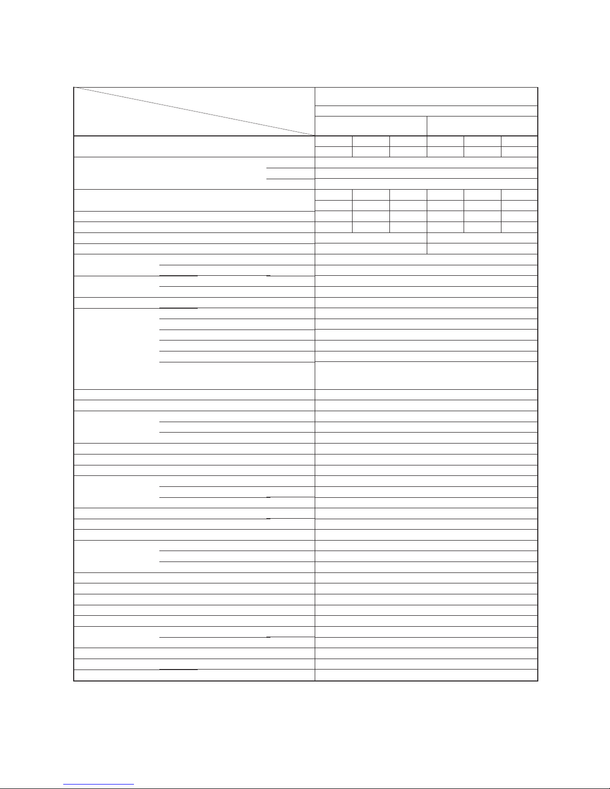
1. SPECIFICATIONS
Specifications are subject to change without notice.
Item
Capacity
Power source
Power consumption
Power factor
Running current
Starting current
Moisture removal
Noise
Refrigerant
Refrigerant control
Interconnection pipe
Condensate drain pipe
INDOOR UNIT
Dimensions
Net weight
Evaporator type
Indoor fan type
Air volume
Fan motor output
Air filter
OUTDOOR UNIT
Dimensions
Net weight
Condenser type
Outdoor fan type
Airflow volume
Fan motor output
Compressor
Safety device
Auto louver
Usable outdoor temperature range
*1
A
Indoor (H/M/L)
Outdoor
Name of refrigerant
Rated volume
Gas side size
Connection type
Liquid side size
Connection type
Maximum length (of one way)
Maximum height difference
Indoor unit
Outdoor unit
Outer diameter
Height
Width
Depth
High fan
Medium fan
Low fan
Height
Width
Depth
(220/230/240V)
Model
Output
Model
kW
Phase
V
Hz
kW
%
Indoor/Outdoor
A
lit/h
dB
dB
kg
mm
mm
m *2
m
mm
mm
mm
mm
kg
m3/h
m3/h
m3/h
W
mm
mm
mm
kg
m3/h
W
W
°C
RAS-10SK-E (2 units) / RAS-M18SA-E
RAS-10SKX (2 units) / RAS-M18SAX
COOLING
1 Indoor unit 2 Indoor units
(A or B) (A + B)
220V 230V 240V 220V 230V 240V
2.6 2.6 2.6 5.2 5.2 5.2
Single
220/230/240
50
220V 230V 240V 220V 230V 240V
0.89 0.91 0.94 1.78 1.82 1.88
97 97 96 97 97 96
0.15/4 0.15/3.95 0.15/3.95 0.3/8 0.3/7.9 0.3/7.9
16 32
1.15 2.3
44/36/31
52
R-22
1.3 (0.65 x 2)
Capillary tube
9.52
Flare connection
6.35
Flare connection
15
5
16
RAS-10SK-E, RAS-10SKX
265
790
174
8
Finned tube
Cross flow fan
650
510
430
19
Polypropylene net filter (Washable)
RAS-M18SA-E, RAS-M18SAX
538
830
300
52
Finned tube
Propeller
1830/1920/2010
28
PH102T1-4C
750
Fuse, Overload relay
Yes
21 ~ 43
– 5 –
Notes : *2
• This air conditioner accepts a connection piping length of up to 15m and a head of up to 5m.
• There is no need to add the refrigerant as long as the total length of the connection piping is up to 10m.
• There is need to add the refrigerant 10g/m as long as the each length of the connection piping is up from 11m
to 15m.
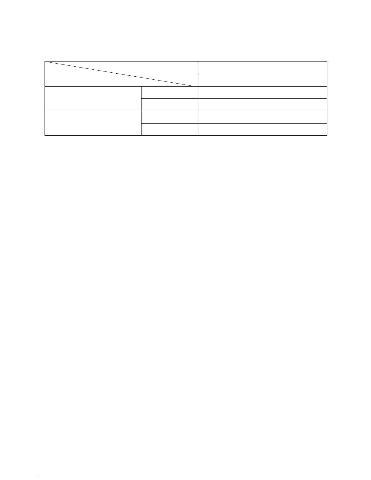
Note : *1
• Capacity is based on the following temperature conditions.
T emperature
Indoor unit inlet air temperature
Outdoor unit inlet air temperature
Condition
(DB)
(WB)
(DB)
(WB)
JIS C9612-1994
Cooling
27°C
19°C
35°C
24°C
– 6 –
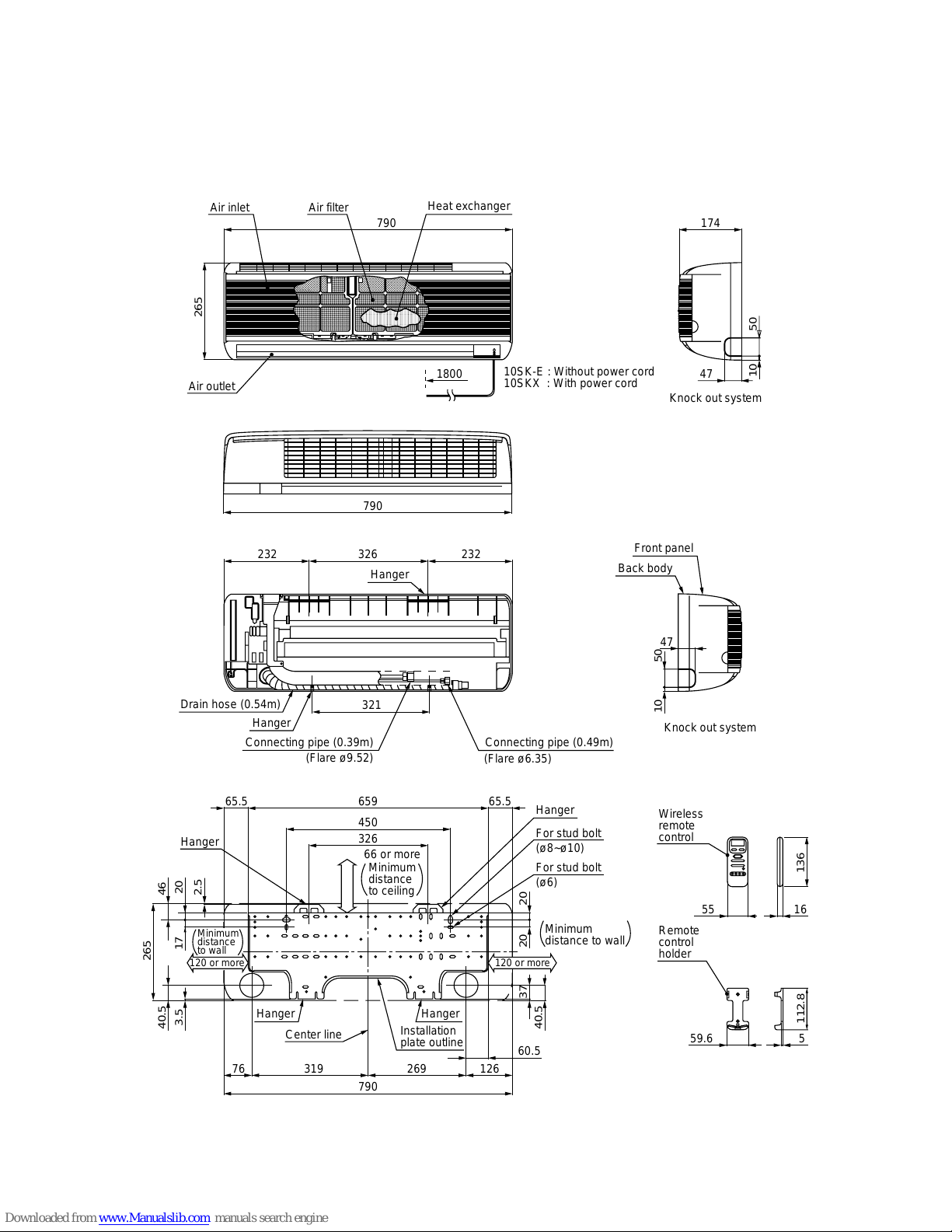
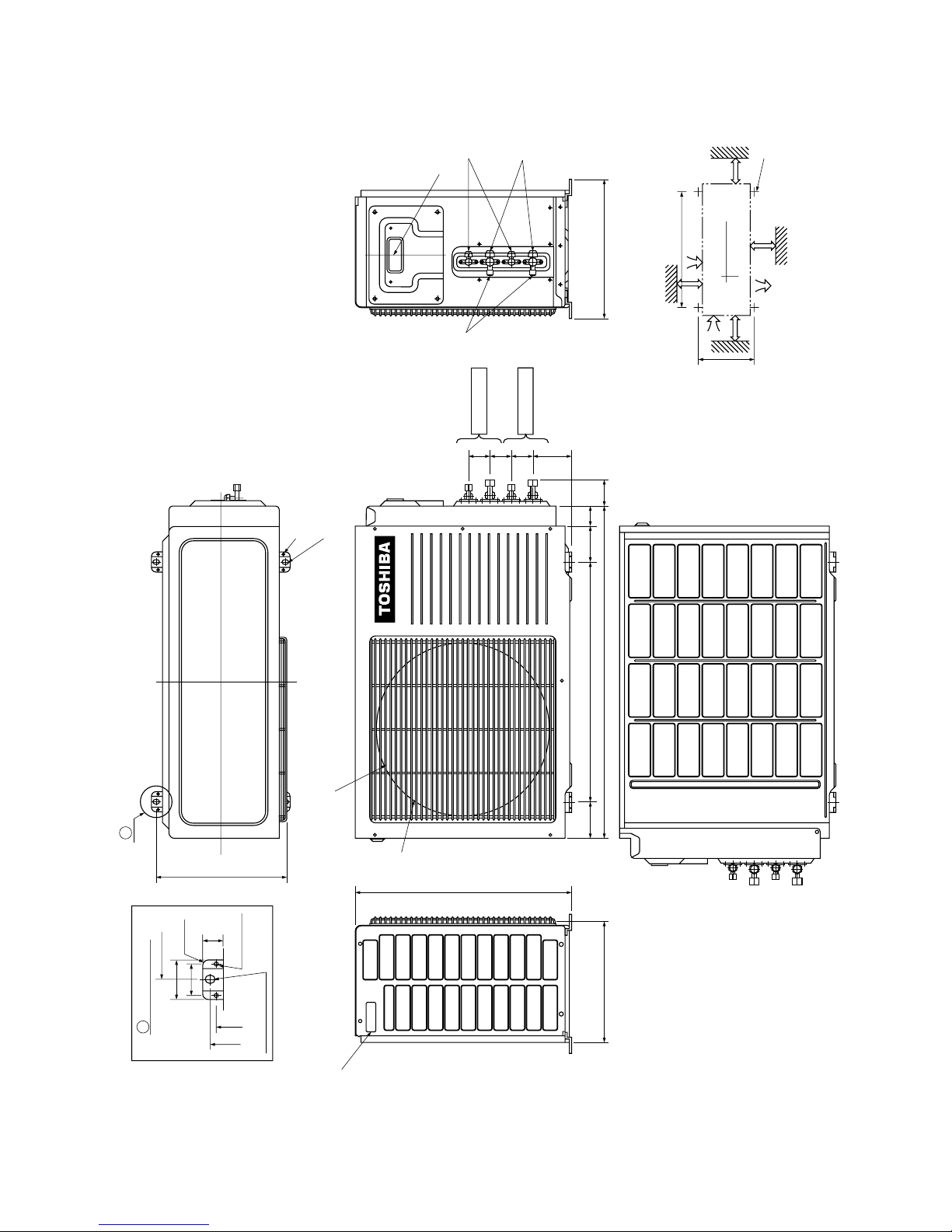
2. CONSTRUCTION VIEWS
2-1. Indoor Unit
RAS-10SK-E
RAS-10SKX
,,,,,,,,,,,,,,,,
,,,,,,,,,,,,,,,,
,,,,,,,,,,,,,,,,
,,,,,,,,,,,,,,,,
,,,,,,,,,,,,,,,,
,,,,,,,,,,,,,,,,
,,,,,,,,,,,,,,,,
,,,,,,,,,,,,,,,,
,,,,,,,,,,,,,,,,
,,,,,,,,,,,,,,,,
,,,,,,,,,,,,,,,,
,,,,,,,,,,,,,,,,
,,,,,,,,,,,,,,,,,
,,,,,,,,,,,,,,,,,
,,,,,,,,,,,,,,,,,
,,,,,,,,,,,,,,,,,
,,,,,,,,,,,,,,,,,
,,,,,,,,,,,,,,,,,
,,,,,,,,,,,,,,,,,
,,,,,,,,,,,,,,,,,
,,,,,,,,,,,,,,,,,
,,,,,,,,,,,,,,,,,
,,,,,,,,,,,,,,,,,
,,,,,,,,,,,,,,,,,
Air filter
790
Heat exchanger
Air inlet
265
Air outlet
47
10
50
174
47
10
50
Wireless
remote
control
55
16
559.6
Remote
control
holder
112.8
136
Knock out system
790
232 326 232
Hanger
321
Drain hose (0.54m)
Connecting pipe (0.39m)
(Flare ø6.35)
(Flare ø9.52)
Hanger
65965.5
326
450
65.5
For stud bolt
(ø8~ø10)
For stud bolt
(ø6)
Hanger
Minimum
distance to wall
Minimum
distance
to ceiling
265
Knock out system
Front panel
Back body
20 2037
40.5
60.5
790
12626931976
Center line
Installation
plate outline
HangerHanger
40.5
3.5
Hanger
Minimum
distance
to wall
17 20
46
120 or more 120 or more
66 or more
2.5
Connecting pipe (0.49m)
1800
10SK-E : Without power cord
10SKX : With power cord
– 7 –
325
23
301
325
325
538
54545491
100 or more
100 or more
600 or more
600 or more
Installation dimension
4xø11x14
for ø8-ø10
anchor bolt
600
Air inlet
Air inlet
Air outlet
ø11x14 hole
ø6 hole
R10
600
Detail Drawing
50
36
300
90 600 90 50
830 60 344
A
6-ø11x14 hole
(for ø8-ø10 anchor bolt)
8-ø6 hole
(for fixing outdoor unit)
Liquid side
(Flare ø6.35)
Gas side
(Flare ø12.7)
A
Handle
ø420
Fan guard
Electric
Parts cover
Service port
FOR UNIT B
FOR UNIT A
2-2. Outdoor Unit
RAS-M18SA-E
RAS-M18SAX
– 8 –
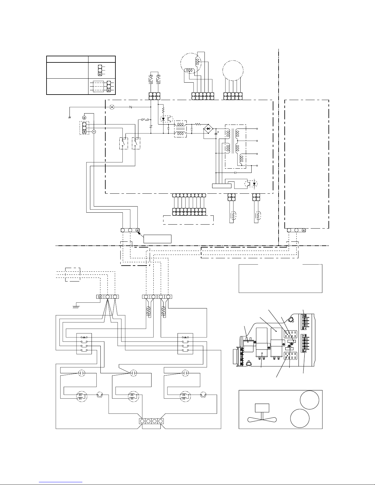
3. WIRING DIAGRAM
1
2
3
4
56789
1
2
3
4
56789
1
23
4
56789
1
2
1
2
1
2
1
2
L
N
1
2
3
4
6
5
IC
Internal circuit is same
as that of INDOOR UNIT A.
INDOOR UNIT B
OUTDOOR UNIT
BLK
BLK
A151311
B161412
BLK
WHI
GRN&YEL
GRN&YEL
P04
BLK
BRW
BLU
PNK
YEL
ORN
RED
BRW
GRY
GRY
BLU
CN04
CN07
CN10
BLU
CN03 CN01
CN13
CN25
BLK
BLK
BLK
BLK
IC01
IC02
C06
DC 35V
DC 12V
DC 7V
DC 0V
T01
MAIN P.C. BOARD
MCC-713
C02
DB01
R01
C01
L01
C15
IC04
R109
F01 FUSE
T3.15A
250V
R21
RY01
RY02
WHI
BLK
3
4
3
4
POWER
TERMINAL
BLOCK
INDOOR
TERMINAL
BLOCK
NO
CONNECTION
INFRARED RAYS RECEIVE
AND INDICATION PARTS
THERMO
SENSOR
(TA)
HEAT
EXCHANGER
SENSOR
(TC)
LOUVER
MOTOR
INDOOR UNIT AINDOOR
UNIT A
FAN MOTOR
:
:
:
:
:
:
:
:
:
:
BROWN
RED
WHITE
YELLOW
BLUE
BLACK
GRAY
PINK
ORANGE
GREEN &
YELLOW
BRW
RED
WHI
YEL
BLU
BLK
GRY
PNK
ORN
GRN&YEL
COLOR IDENTIFICATION
THERMAL FUSE
77˚C x 2
VARISTOR
3
1
1
2
3
4
6
5
1
2
3
4
5
1
2
3
4
5
3
1
DC
MOTOR
SG01
DSA
BLU
BLU
BLU
BLU
BLU
PNK
BLK
WHI
R116
RAS-10SK-E
220/230/240V ~
50Hz
RAS-10SKX
220/230/240V ~
50Hz
L
N
L
N
Model Section A
Section A
1
2
1
2
1
2
BLU
YEL
BLK
RED
WHI
OUTDOOR
TERMINAL
BLOCK
POWER SUPPLY
50Hz
220/230/240V ~
TERMINAL
BLOCK
POWER TERMINAL
BLOCK
SPARK KILLER
RUNNING
CAPACITOR
MAGNETIC RELAY
DSA : Surge absorber
1
2
N
L
WHI
WHI
WHI
RED
RED WHI
WHI
PNK
BLK
BLK
BLK
BLK
BLK BLK
BLK
RED
BLK
BLK
RED
RED
BLK
RUNNING
CAPACITOR
RED
RED
WHI
WHI
RED
BLK
A151311
B161412
RUNNING
CAPACITOR
COMPRESSOR
(FOR UNIT B)
OVER LOAD
RELAY
COMPRESSOR
(FOR UNIT A)
OVER LOAD
RELAY
MAGNETIC RELAY
WHI
RED
RED WHI
WHI
PNK
BLK BLK
RED
BLK
BLK
BLK BLK
RED
RED RED
REDRED
RED
BLK
1 2 3 4
GRN&YEL
Fan
motor
Compressor
(For unit B)
Compressor
(For unit A)
Running capacitor
(For fan motor)
Running capacitor
(For unit B compressor)
Running capacitor
(For unit A compressor)
Magnetic relay
(For unit B)
Magnetic relay (For unit A)
Spark killer
(For unit B)
Spark killer
(For unit A)
TERMINAL BLOCK
(FOR POWER SUPPLY)
Terminal block
(For connecting cable)
FAN MOTOR
Electrical parts position
Parts position
– 9 –
Specifications
Output (Rated) 750W, 2pole, 1phase, 220/230/240V, 50Hz
Winding resistance (Ω)
(at 20°C)
Output (Rated) 28W, 6pole, 1phase, 220/230/240V, 50Hz
Winding resistance (Ω)
(at 20°C)
450V AC, 2µF
400V AC, 25µF
U/T 6.1A (80°C), OPEN 135±5°C, CLOSE 78±11°C
220–240V, 50Hz
AC 500V, 50/60Hz, 0.1µF, 120Ω
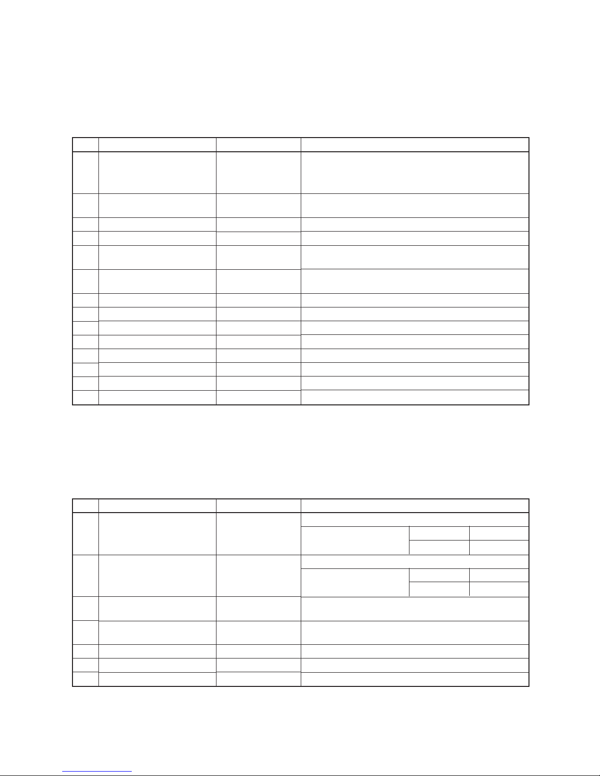
4. SPECIFICATIONS OF ELECTRICAL PARTS
4-1. Indoor Unit
RAS-10SK-E
RAS-10SKX
4-2. Outdoor Unit
RAS-M18SA-E
RAS-M18SAX
No.
1
2
3
4
5
6
7
8
9
10
11
12
13
14
Parts name
Fan motor (for indoor)
Thermo sensor
(TA-sensor)
DC-DC transformer (T01)
Microcomputer
Power relay (RY01),
Common relay (RY02)
Heat exchanger sensor
(TC-sensor)
Line filter (L01)
Diode (DB01)
Capacitor (C02)
Fuse (F01)
Power supply IC (IC01)
Va ristor (R21, R109)
Resistor (R01)
Louver motor
Type
ICF-35-19-3
or
TICF-35-19-3
(microprocessor)
SWT-34
TMP87CK40F
DI1U
(microprocessor)
RF-103YOR6
RBV-406
CEAUF2W101M20
MT3
MA2830-FJ
15G561K
ERF-5TK5R6
MP35EA7
Specifications
DC 35V, 19W
10kΩ at 25°C
DC390V, Secondary DC35V, 12V, 7V
Coil : DC12V 75mA, Rated AC250V 20A
10kΩ at 25°C
10mH, AC 0.6A
4A, 600V
100µF, 450V
T3.15A, 250V
4A, 600V
560V
5.6 Ω, 5W
Output (Rated) 2W, 10poles, 1phase DC 12V
No.
1
2
3
4
5
6
7
Parts name
Compressor
Fan motor
Running capacitor
(for fan motor)
Running capacitor
(for compressor)
Overload relay
Magnetic relay
Spark killer
Type
PH102T1-4C
AF-230-28P
SK-45FMP
SK-40CMP25U1
J-MRA99285-9201
VC 20FA
RFM50S104KD2
Red-Black White-Black
3.88 5.06
Red-Black White-Black
162.1 233.5
– 10 –
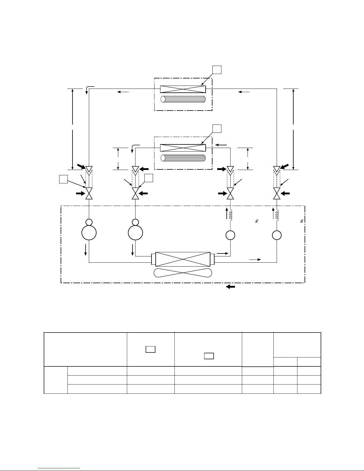
5. REFRIGERANT CYCLE DIAGRAM
RAS-10SK-E x 2 / RAS-M18SA-E
RAS-10SKX x 2 / RAS-M18SAX
Condenser
Cooling
Cooling
Packed valve
(ø6.35)
Packed valve
(ø9.35)
Packed valve
(ø9.35)
Packed valve
(ø6.35)
0.49m
(Connecting pipe)
ø6.35
O.D.:6.35mmO.D.:9.52mm
O.D.:9.52mm
0.39m
(Connecting pipe)
ø9.52
O.D.:6.35mm
0.49m
(Connecting pipe)
ø6.35
0.39m
(Connecting pipe)
ø9.52
Evaporator
INDOOOR UNIT A
Cross flow fan
Optional piping kits
RB-P31BFH1 (3m)
RB-P51BFH1 (5m)
RB-P71BFH1 (7m)
T1
Evaporator
INDOOR UNIT B
Cross flow fan
T1
P
P
Propeller fan
Capillary
tube
ø1.5x1100
Strainer Strainer
Capillary
tube
ø1.5x1100
Compressor
B
PH102T1-4C
Compressor
A
PH102T1-4C
OUTDOOR UNIT
Mark ( ) means check points of Gas Leak
Refrigerant
R-22 1.3kg
(0.65kgx2)
Note :
• Measure the heat exchanger temperature at the center of U-bend. (By means of TC sensor.)
Fig. 5-1
Table 5-1
50Hz
Standard
Cooling High temperature
Low temperature
Standard pressure
P
(kg/cm²G)
5.0
6.5
4.0
Surface temp. of heat
exchanger interchanging
pipe T1 (°C)
13.0
18.0
2.0
Fan speed
(indoor)
High
High
Low
Ambient temp.
conditions DB/WB
(°C)
Indoor Outdoor
27/19 35/24
32/23 43/26
21/15 21/15
– 11 –
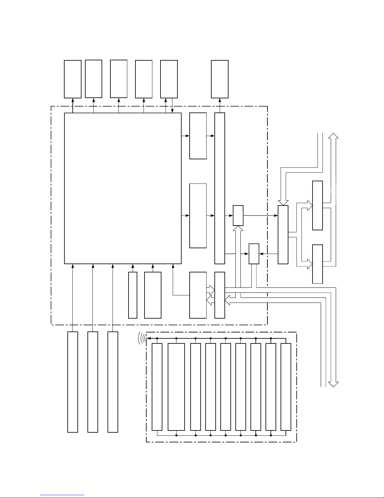
6. MICRO-COMPUTER BLOCK DIAGRAM
Infrared Rays Signal Receiver
Functions
ECONO.
Louver Direction Setting
Louver AUTO Swing
OFF TIMER Setting
ON TIMER Setting
Fan Speed Selection
Thermo Setting
Operation Mode Selection
AUTO, COOL, DRY, FAN ONLY
Operation (START/STOP)
Clock Frequency
Oscillator Circuit
Heat Exchanger Sensor
Infrared
Rays
Initializing Circuit
C. P. U
Main Unit Control Panel
AC 220/230/240V~
50Hz
Remote Control
Operation
Display
Timer
Display
ECONO.
Sign Display
FAN-ONLY
Sign Display
Indoor
Fan Motor
Compressor, Outdoor Fan
ON/OFF Signal
Louver
Motor
RY02
RY01
Thermo Sensor
• Louver Control
• 3-minute Delay at Restart for Compressor
• Motor Revolution Control
• Processing
(Temperature Processing)
• Timer
Magnetic Relay
AC 220/230/240V~
50Hz
Relay Driver, Louver Driver
Relay
Power Supply
Circuit
Louver
ON/OFF Signal
Noise Filter
Relay
Compressor Outdoor Fan Motor
– 12 –
7. OPERATION DESCRIPTIONS
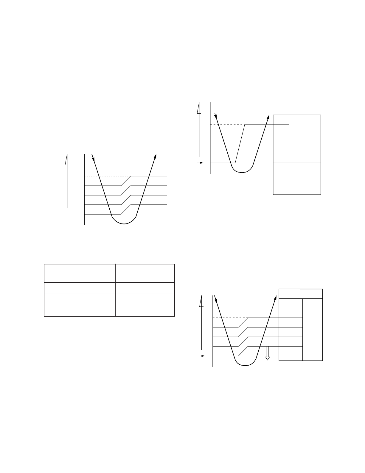
7-1. FAN ONLY Operation
(MODE of the remote control : FAN ONLY)
(1) During this mode, the relay RY01 is alwa ys turned
off so that only the indoor fan is operated. RY02 is
always turnd on. FAN-ONLY display is lit.
1) When the FAN is set to AUTO, the indoor fan
motor operates as shown in Fig 7-1-1.
2) When the FAN is set to LOW, MED, or HIGH,
the indoor fan motor operates with a constant
in volume as listed in Table 7-1-1.
7-2. COOL Operation
(MODE of the remote control : COOL)
(1) Compressor, outdoor fan and operation displa y are
controlled as shown in Fig. 7-2-1.
Fig. 7-2-2
(3) Once the setting is made, the operation mode is
memorized in the microcomputer so that the same
operation can be effected thereafter simply by
pushing the START/STOP button.
Fig. 7-1-1 Auto setting of air volume
Table 7-1-1 Manual setting of FAN SPEED
(2) Once the setting is made, the operation mode is
memorized in the microcomputer so that the same
operation can be effected thereafter simply by
pushing the START/STOP button.
Fig. 7-2-1
(2) Relays R Y01 and R Y02 are turned on to energize
the outdoor unit, and a cool operation is carried
out.
1) When the FAN is set to AUTO, the indoor fan
motor operates as shown in Fig 7-2-2.
2) When the FAN is set to LOW, MED, or HIGH,
the indoor fan motor operates with a constant
in volume as listed in Table 7-1-1.
(Room temp. – Set temp.)
MED
LOW(+)
LOW
LOW
(continuous)
+4
+3
+2
+1
0
RY01
OFF
Set
temp.
Manual
FAN
According
to the set
position
HIGH
AUTO
(Room temp. – Set temp.)
+1
0
Set
temp.
ON
OFF
OPERATION
display
ON ON
Compressor
Outdoor fan
(RY01)
Common relay
(RY02)
HIGH
MED
LOW(+)
LOW
LOW
28
27
26
25
24
Room temp.
Indication of
FAN SPEED
LOW
MED
HIGH
HIGH Air volume
(m3/h)
430
510
650
– 13 –
7-2-1. Louver Control
(1) By pushing the SET button of the remote control
during the operation, the louver can be set to the
desired position.
And the louver position is stored in the microcomputer, the louvers will be set to the position automatically at the next operation.
(2) When the AUT O b utton is pushed, the louv er v er-
tically swings within range of 25deg.
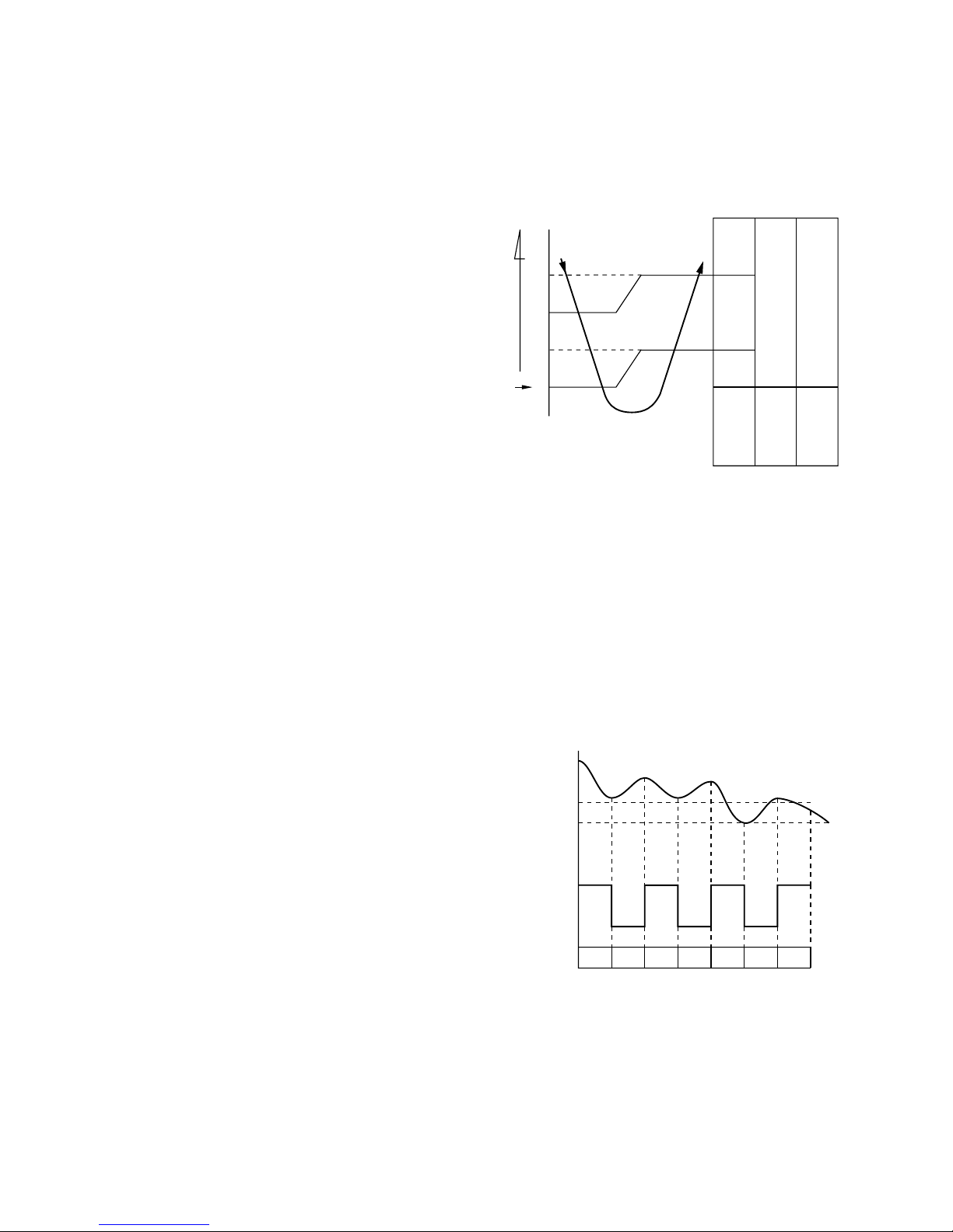
7-3. DRY Operation
(MODE of the remote control : DRY)
(1) Compressor, outdoor fan and operation displa y are
controlled as shown in Fig. 7-3-1.
Fig. 7-3-2
Fig. 7-3-1
• The microprocessor turns the compressor on
and off at regular intervals (4 to 6 minutes on
and/or off). During the compressor off, the indoor fan will operate in the super low position.
• The indoor fan will operate in the AUTO position.
(2) The pattern of operation depending on the rela-
tion between room temperature and set temperature is shown below:
Room temp.
Set temp.+1
Set temp.
Compressor
Outdoor fan
Indoor fan
L.*S.L. S.L.L. L. S.L. L.
ON ON ON ON
OFF OFF OFF
*
Super Low
(Room temp. – Set temp.)
Set
temp.
ON
+3
+2
+1
0
OFF
OPERATION
display
Compressor
Outdoor fan
(RY01)
Common relay
(RY02)
ON:6min.
OFF:4min.
ON:5min.
OFF:5min.
ON

– 14 –
7-4. AU TO Operation
(MODE of the remote control : AUTO)
(1) One of the 2 modes, Cooling or Dry is selected
according to room temperature at which operation is to start, as shown in Fig. 7-4-1. The Fan
mode will continue until room temperature reaches
a level at which another mode is selected.
7-4-1. Temporary Auto
When the TEMPORAR Y button is pushed, the set temperature is fixed at 24°C and controlled in accordance
with the chart shown in Fig. 7-4-1.
Fig. 7-4-1
Cooling mode
Cooling mode
Dry mode
+4
+1
(The same cooling mode as the room temperature control is set at set temp. –1˚C)
The Louver moved downward.
(The same cooling mode as the room temperature control is set at set temp. –1˚C)
(The same dry operation as the room temperature control is set at set temp. –1˚C)
(Room temp. – Set temp.)
– 15 –
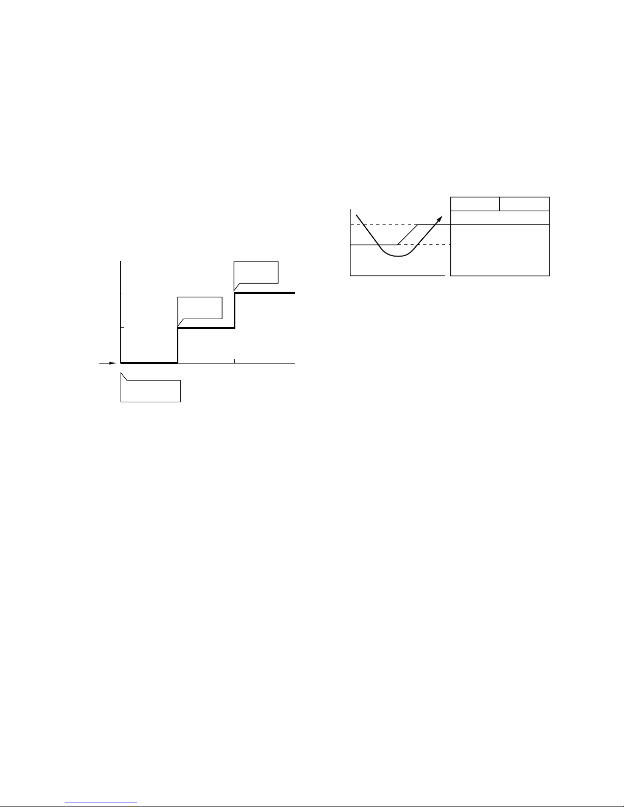
7-5. ECONO. Mode
When the ECONO. button is pushed, during COOL
and AUTO operation, the OPERATION display is
turned off and the ECONO. display is lit and the indoor unit operates quietly and mildly with controlling
airflow.
7-5-1. Cooling
(1) In the ECONO. mode, the set temp. by the remote
control is changed automatically as shown in Fig.
7-5-1.
(2) Fan speed → LOW
+2
+1
Set temp.
1H 2H TIME0H
(˚C)
ECONO. button
is pushed
Set temp.
is changed
Set temp.
is changed
7-6. Low-Temperature Limit Control
(Cooling Operation)
The microprocessor detects the indoor heat exchanger
temperature so as to prevent freezing up the indoor
heat exchanger.
Control is performed as shown in Fig. 7-6-1.
Fig. 7-5-1
Compressor
Less than 5˚C continues
for 5 minutes
OFF
ON
Outdoor fan
7
Heat exchanger
temperature
5
(˚C)
Fig. 7-6-1
– 16 –
7-7. Auto Restart Function
This unit is equipped with an Automatic restarting facility which allows the unit to restart and resume the
set operating conditions in the event of a power supply shutdown without the use of the hand control.
The operation will resume without warning three minutes after the power is restored.
The Auto Restart function is set not to work on shipment from the factory, and so it is necessary to set it
to function as required.
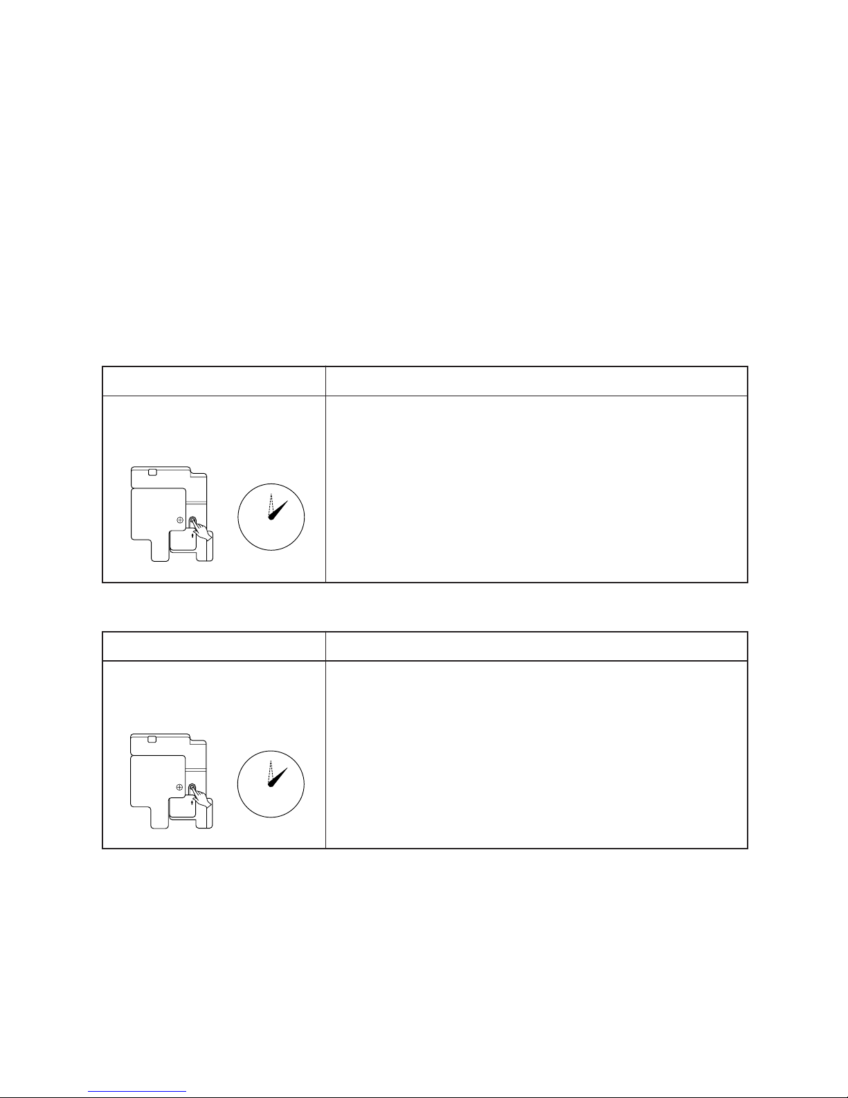
7-7-1. How to Set the Auto Restart
To set the Auto Restart function, proceed as follows:
Access the TEMPORARY button located in the lower
right hand corner beneath the hinged front panel of
the indoor unit (please refer to section on PARTS
NAME). The po wer supply to the unit must be on - the
function will not be set if the power is off.
To enable the Auto Restart function, press the TEMPORARY button continuously for three seconds.
The unit will acknowledge the setting and beep three
times. The system will now restart automatically.
The above A uto Restart settings can be carried out:
During subsequent operation, the orange light is lit.
• The Auto Restart function will not accept an instruction if timer operation with the remote control is
selected.
(Please refer to the section on setting the timer or
setting the louver.)
• When the system is stand-by (not running)
• During louver swing (A UT O) operation, after restart
by the Auto Restart function the louver swing stops.
• When the system is operating
TEMPORARY
0
3S
TEMPORARY
0
3S
OPERATION
Press the TEMPORARY button
continuously more than three
seconds.
MOTION
Stand-by
↓
The system starts to operate. The green light will be lit.
↓ about three seconds after
The unit beeps three times. The orange light will be lit.
↓
The system is operating. The orange light is lighting.
If the system is not required to run at this time, press the TEMPORARY
button once more or use the remote control and the unit will stop.
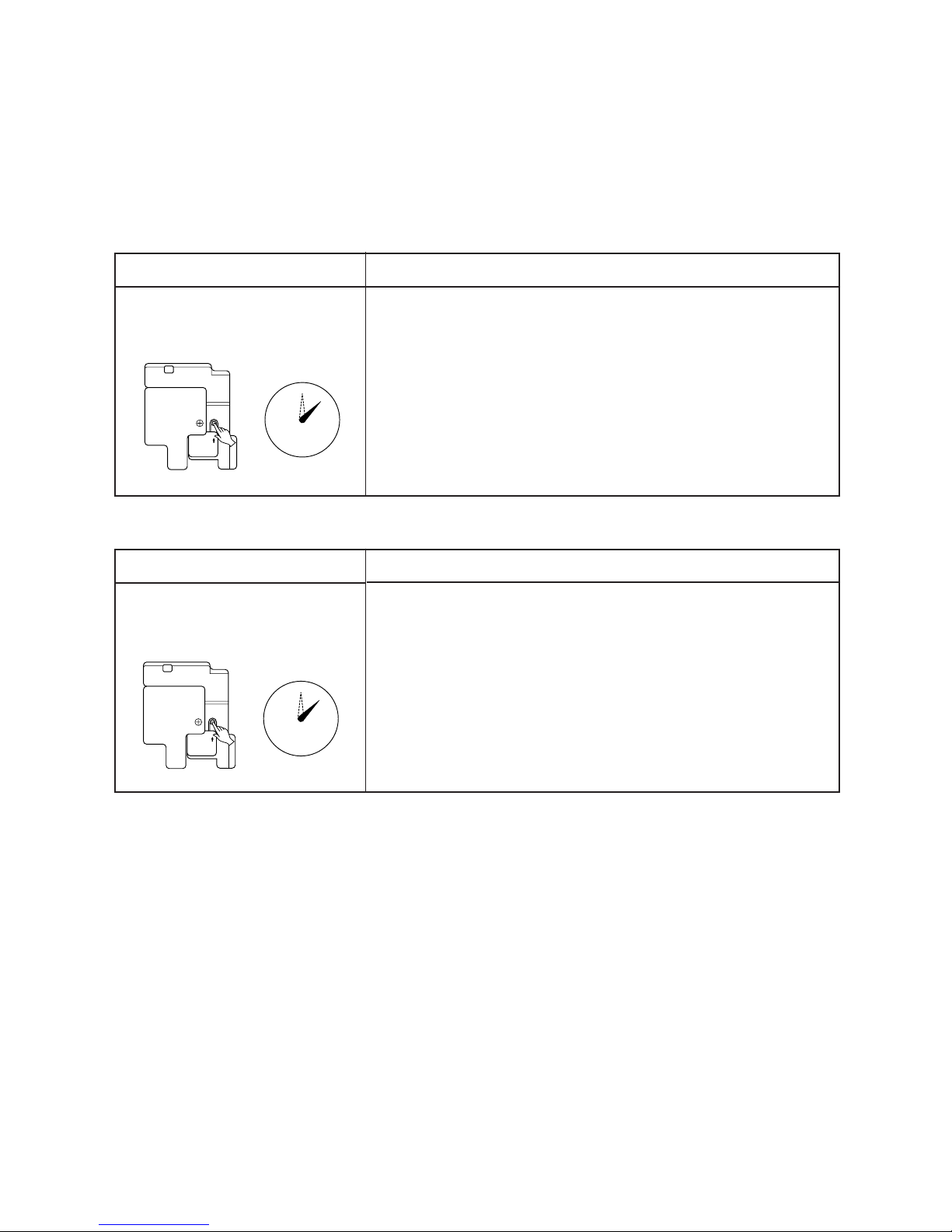
OPERATION
Press the TEMPORARY button
continuously more than three
seconds.
MOTION
Operating The green light is lit.
↓
The system stops to operate. The green light is turned off.
↓ about three seconds after
The unit beeps three times.
↓
The system stops.
If the system is not required to stop at this time, use the remote control
and to restart.
– 17 –
7-7-2. How to Cancel the Auto Restart
To cancel the Auto Restart function, proceed as follows:
Repeat the setting procedure: the unit will acknowledge the instruction and bleep three times.
The system will now be required to manually restart
with the remote control after the main supply is turned
off.
Cancellation is carried out:
• When the system is stand-by (not running)
• When the system is operating
During subsequent operation, the green light is lighting.
7-7-3. In Case of Power Failure during the
Timer Operation
(1) If ON-TIMER operation is reserved with setting of
Auto Restart operation, it is cancelled with power
failure. (The OPERATION lamp on the main unit
goes on and off to inform of power failure.) In that
case, try to reserve ON-TIMER operation once
again.
TEMPORARY
0
3S
TEMPORARY
0
3S
(2) If OFF-TIMER operation is reserved without set-
ting of Auto Restart operation, the reservation is
cancelled with power failure. (The OPERATION
lamp on the main unit goes on and off to inform of
power failure.) In that case, try to reserve OFFTIMER operation. When Auto Restart operation
is set, OFF-TIMER reservation is also cancelled
with power failure.
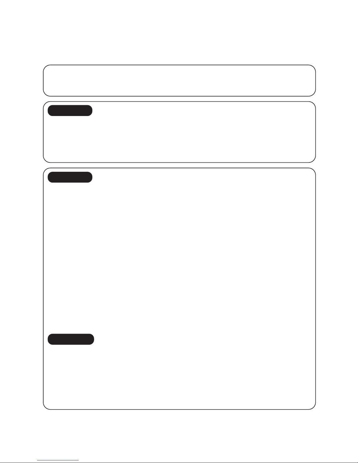
OPERA TION
Press the TEMPORARY button
continuously more than three
seconds.
MOTION
Stand-by
↓
The system starts to operate. The orange light will be lit.
↓ about three seconds after
The unit beeps three times. The green light will be lit.
↓
The system is operating.
If the system is not required to run at this time, press the TEMPORARY
button once more or use the remote control and the unit will stop.
OPERATION
Press the TEMPORARY button
continuously more than three
seconds.
MOTION
Operating The orange light is lit.
↓
The system stops to operate. The orange light is turned off.
↓ about three seconds after
The unit beeps three times.
↓
The system stops.
If the system is not required to stop at this time, use the remote control
and to restart.
– 18 –
8. INSTALLATION PROCEDURE
8-1. Safety Cautions
For general public use
Power supply cord of parts of appliance for Outdoor use shall be more than polychloroprene sheathed flexible
cord (design H05 RN-F), or cord designation 245 IEC 57.
CAUTION
TO DISCONNECT THE APPLIANCE FROM THE MAINS SUPPLY.
This appliance must be connected to the mains by means of a circuit breaker or a switch with a contact
separation of at least 3 mm.
If this is not possible, a power supply plug with earth must be used. This plug must be easily accessible after
installation. The plug must be disconnected from the power supply soc ket in order to disconnect the appliance
completely from the mains.
DANGER
` FOR USE BY QUALIFIED PERSONS ONLY.
` TURN OFF MAIN POWER SUPPLY SWITCH AND BREAKER OF OUTDOOR UNIT AND INDOOR UNIT
BEFORE ATTEMPTING ANY ELECTRICAL WORK.
INDIVIDUAL POWER SUPPLY IS PROVIDED IN THIS OUTDOOR UNIT. MAKE SURE ALL POWER
SWITCHES AND BREAKER TURN OFF. FAILURE TO DO SO MAY CAUSE ELECTRICAL SHOCK.
` CONNECT THE CONNECTING CABLE CORRECTLY. IF THE CONNECTING CABLE IS CONNECTED BY
WRONG WAY, ELECTRIC PARTS MAY BE DAMAGED.
` CHECK THE EAR TH WIRE IS NOT BROKEN OR DISCONNECTED BEFORE INSTALLATION.
` DO NOT INSTALL NEAR CONCENTRATIONS OF COMBUSTIBLE GAS OF GAS VAPORS.
FAILURE TO FOLLOW THIS INSTRUCTION CAN RESULT IN FIRE OR EXPLOSION.
` TO PREVENT OVERHEATING THE INDOOR UNIT AND CAUSING A FIRE HAZARD, PLACE THE UNIT
WELL AW AY (MORE THAN 2M.) FROM HEAT SOURCES SUCH AS RADIA T ORS, HEAT RESISTORS, FUR-
NACE, STOVES, ETC..
` WHEN MOVING THE AIR-CONDITIONER FOR INSTALLING IT IN ANOTHER PLACE AGAIN, BE VERY
CAREFUL NOT TO GET THE SPECIFIED REFRIGERANT (R-22) WITH ANY OTHER GASEOUS BODY
INTO THE REFRIGERATION CYCLE. IF AIR OR ANY O THER GAS IS MIXED IN THE REFRIGERANT, THE
GAS PRESSURE IN THE REFRIGERATION CYCLE BECOMES ABNORMALL Y HIGH AND IT RESUL TINGLY
CAUSES BURST OF THE PIPE AND INJURIES ON PERSONS.
` IN THE EVENT THAT THE REFRIGERANT GAS LEAKS OUT OF THE PIPE DURING THE INSTALLATION
WORK, IMMEDIATELY LET FRESH AIR INTO THE ROOM. IF THE REFRIGERANT GAS IS HEATED BY
FIRE OR SOMETHING ELSE, IT CAUSES GENERATION OF POISONOUS GAS.
WARNING
• Never modify this unit by removing any of the safety guards or by by-passing any of the safety interlock
switches.
• Do not install in a place which cannot bear the weight of the unit.
Personal injury and property damage can result if the unit falls.
• Before doing the electrical work, attach an approved plug to the power supply cord.
And make sure the equipment to be earthed.
• Appliance shall be installed in accordance with national wiring requlations.
If you detect any damage, do not install the unit. Contact your Toshiba dealer immediately.
 Loading...