

Toshiba RAS-B10UFV-E, RAS-137SKV-E5, RAS-167SKV-E5, RAS-B16N3KVP-E, RAS-B13UFV-E Technical Handbook
...
Version 14.1.3
24 Hour Technical Helpline: 0870 843 0333
Fault & DN Code Apps: Android & iPhone
Web Page toshiba-calc.co.uk/fault-codes/
Fault Code Text Service: 07624 803 017
technical.enquiries@toshiba-ac.com
Technical HandBook

Page 2 of 78
Index Page
Make Up of Model Number 3
Mechanical Specifications-RAS R410A Outdoor Units 4
Performance & Electrical Specifications - RAS R410A Single Splits 4
Performance & Electrical Specifications - RAS R410A Multi Splits 4
RAS R410A Multi Split System Combinations 5
Acoustic Data - RAS Indoor Units 5
RAS - Auto Restart Function 6
Fault Codes - RAS “N” Series 6
Mechanical Specifications - DI/SDI R410A Single Splits 7
Performance & Electrical Specifications - DI / SDI R410A Single Splits 7
Electrical Specifications - DI/SDI R410A Multi Splits 8
Acoustic Data – DI/SDI Indoor Units 8
Mechanical & Electrical Data - Air-to-Air Heat Exchangers 9
Digital/Super Digital Replacement Refrigerant Pipe Sizing 10
Digital/Super Digital Inverter Multi Split System Combinations 11
Digital/Super Digital Inverter Twin Splits 12
Digital/Super Digital Inverter Triple Splits 14
Digital Inverter Quad Splits 16
Digital/Super Digital Multi Split System Wiring Schematic 17
VRF System Make Up Chart 18
Electrical Data - VRF Outdoor Units 19
VRF Additional Refrigerant Charge Amount 19
VRF Additional Refrigerant Charge Calculations 20
Acoustic Data - MMY Indoor Units 23
Common Sensor Characteristics 24
Trouble Shooting - RAV Series 25
Apps Store Fault Codes - All Commercial & VRF Systems 28
Fault Codes – All Commercial & VRF Systems 29
Error Detected by TCC-Link Central Controller 43
Step By Step Wiping/Re-addressing Of VRF Systems 44
Priority Mode (SMMSi Only) 44
Outdoor Fan High Static Pressure Setup 44
Compressor or Outdoor Fan Motor Backup Isolation Setting 44
VRF Rotary Dial Data Display SMMSi, SHRMi & Mini SMMS 45
TCC-net Controller Guidelines 46
System Configuration Menu 47
TCCJ Optional Control Accessories 49
TCC-Net Control - Standard Wired Controller 50
Controller Configuration - Remote Controller RBC-AMT32E & RBC-AMS41E 51
Data Retrieval Guide - Remote Controllers RBC-AMT32E, RBC-AMS41E & RBC-AMS51E 52
Simplified Instructions for RBC-AMS41E Remote Controller 54
Time, Temperature & Mode Setting for RBC-AMS41E Remote Controller 55
Simplified Instructions for RBC-AMS51E Remote Controller 56
Fault Code Guide for RBC-AMS51E Remote Controller 57
Data Retrieval Guide - RBC-AMS51E Remote Controller 58
Relocation of Room Temperature Sensing from Return Air to Remote Controller 59
Automatic Restart after Power Failure 60
Condition Setting (Day, Time, Mode & Temperature) 62
Delete Settings for each Day 63
Copy Settings for Previous Day 63
Holiday Day Omit Setting 64
Energy Saving Function 64
VN Air to Air Heat Exchangers 66
VN Air to Air Heat Exchanger Configurations 68
Automatic Zone Registration Using the Central Remote Controller (TCB-SC642TLE) 69
Network Addressing DI/SDI and VRF Systems 70
Integration with AI Network Control 76
Second Controller 76
Temperature Sensing 76
E = CE marked
P = Made in Thailand
T = Twin rotary compressor
V = Single rotary compressor
R = Infrared option
Style
X = Flexi (Low Wall or Under-slung)
K = Hi Wall, C = Ceiling Suspended
U = Cassette, B = Ducted
A = Outdoor
RAV/RAS Products
RAS - 16 7 SK_PE
Digital/Super Digital Inverter
RAV-SM566KRTP-E
SMMSi/SHRMi
MMYMAP 1204HT8E
Modular Multi Indoor Units
MM* - AP 056 4 BH E
009= 2.8kW 012= 3.6kW 015= 4.5kW 018= 5.6kW 024= 7.1kW 027= 8kW 030= 9kW 036= 11.2kW 048= 14kW 056= 16kW
*Style
U = Cassette, F = Tall Floor standing
D = Ducted, C = Ceiling suspended
K = High Wall, L = Floor standing
Refrigerant R410A
Capacity Rank
MMY = Modular Multi
M = Single module
No mark = Combined model
Refrigerant R410A
Capacity rank HP x 10
E = CE marked
Three phase power supply
Capacity variable unit (Inverter)
H = Heat pump (two pipe)
F = Heat recovery (three pipe)
Development series
RAV = Light Commercial Range
SM = Digital Inverter
SP = Super Digital Inverter
Nominal Duty (kW) i.e. 56 = 5.6kW
Generation: 0 = original
3 = 3
rd
Update etc
RAV = Light Commercial Range
RAS = Small Office / Domestic
Approx Duty (x 1000 = BTU)
Generation
RAV use numbers i.e. 0,1,2,3,4,5
RAS use letters i.e. U,E,S,Y
E = CE marked
P = Made in Plymouth
Blank = Single Phase Power Supply
8 = Three Phase Power Supply
H = HP (RAV)
N = Chassis Type, K = High Wall
L = Console Type, C = Ceiling suspended
S = Low Wall, F = Tall Floor
B = Ducted Type, U = Four Way Cassette
A = Outdoor Unit TU = Two Way Cassette
E = CE marked
Style
WH = 2-way discharge, H = Heat pump
SH = 1-way discharge, SPH = Slim Duct
BH = Standard duct
Development series
Make Up of Model Number
Page 3 of 78
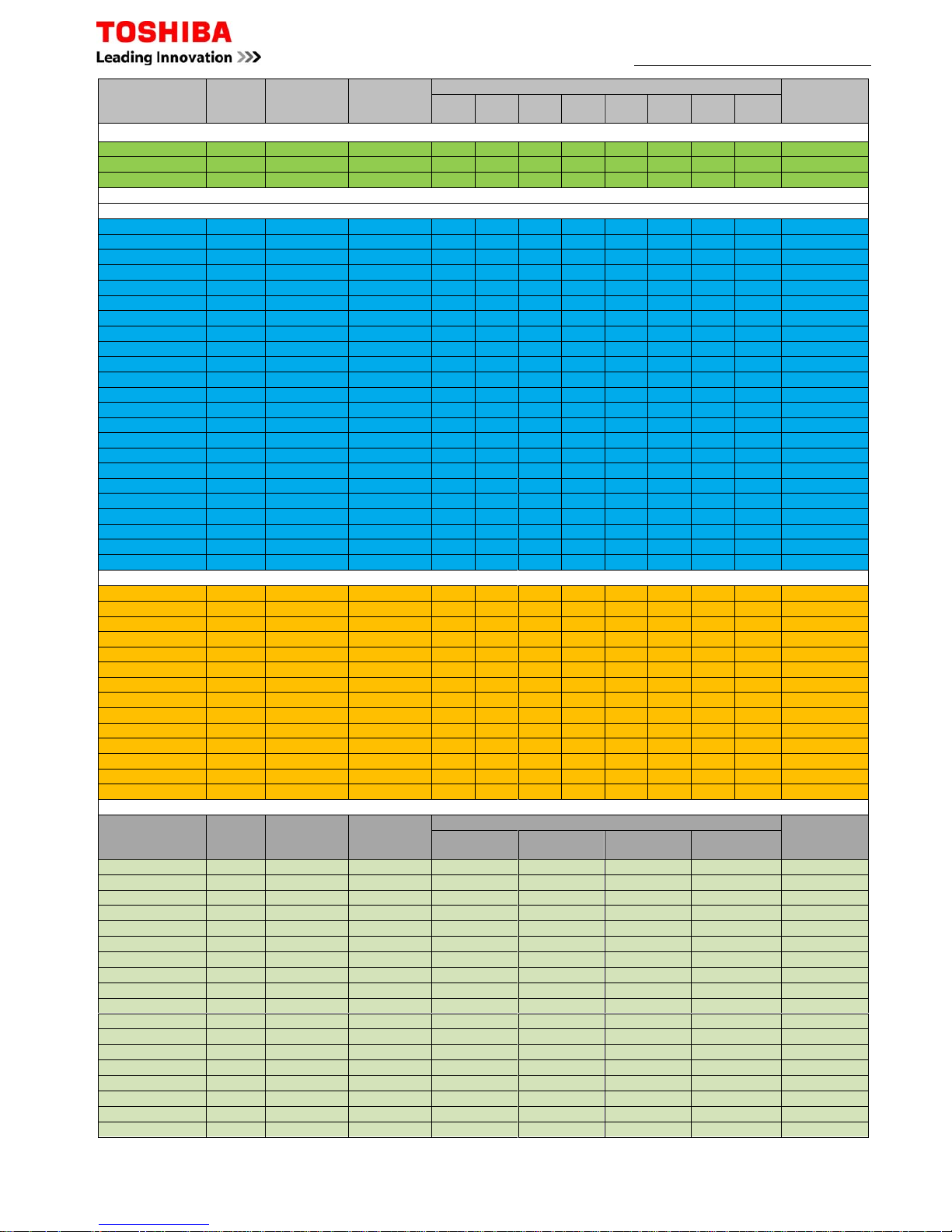
Mechanical Specifications - RAS R410A Outdoor Units
Page 4 of 78
Model
Pipe Sizes
Min/Max
Pipe Sep
(m)
Max
Height
Separation
Pre-
charge
(m)
Add
Charge
(g/m)
Base
Charge
(kg)
Dimensions
(mm)
Weight
(kg)
Liquid Suction
RAS Outdoor Units
RAS-107SAV
-
E6
1/4
3/8 2/15 8 15 N/A 0.63 530x660x240
27
RAS-137SAV
-E630
RAS-167SAV
-E51/2
2/20
10 15
20
1.05
550x780x290
40
RAS-10N3AVP
-
E
3/8
2/25 630x800x300 41
RAS-13N3AVP
-ERAS
-
16N3AVPE
1/2
RAS-10N3AV2
-
E
3/8
2/20 10 15 550x780x290
33
RAS-13N3AV2
-ERAS-16N3AV2
-E1/239RAS
-
M14GVAE
3/8
2/30 10 20
0.90
550x780x290
36
RAS-M18UAV
-
E
1/2
1.20
41
RAS-3M26UAV
-
E
70
15 40
2.40
890x900x320
69
RAS-4M27UAV
-ERAS-5M34UAV
-E180
2.99
75
Performance & Electrical Specifications - RAS R410A Single Splits
Model
Capacity
(kW)
Sensible
Capacity
(kW)
Energy
Rating
Cool/Heat Phase
PowerToSoft
Start
Max
Current
Suggested
Fuse Size
Interconnect
Cable
Cool Heat
RAS Split Systems
RAS-107SAV-E6
2.50 3.20
2.13 A/A
1Ph + N Outdoor Yes
4.19 10
3Core + Earth
RAS-137SAV-E6 3.15 3.60 2.51 A/A 5.37 10
RAS-167SAV-E5 4.87 4.65 3.70 A+/A 7.58 16
RAS-10N3AVP-E
3.30 4.62
2.48 A+++/A+++ 3.42 10
RAS-13N3AVP-E 4.07 4.91 3.05 A++/A+ 4.78 10
RAS-16N3AVP-E
4.50 5.80
3.38 A++/A+ 7.12 16
RAS-10N3AV2-E
3.02 3.60
2.53 A++/A+ 3.60 10
RAS-13N3AV2-E 3.99 4.05 2.79 A++/A 5.66 10
RAS-18N3AV2-E
5.55 4.73
3.89 A+/A 8.79 16
Performance & Electrical Specifications - RAS R410A Multi Splits
Model
Min-Max
Indoors
Capacity (kW)
Energy
Rating
Cool/Heat
Phase
PowerToSoft
Start
Max
Current
Suggested
Fuse Size
Interconnect
Cable
Cool Heat
RAS Multi Systems
RAS-M14GAV-E 1 - 2 1.10 - 4.50 0.90 - 5.20 A+/A
1Ph + N Outdoor Yes
5.47 16
3Core +Earth
RAS-M18UAV-E 2 - 2 1.40 - 6.20 0.90 - 8.30 A++/A++ 7.93 16
RAS-3M26UAV-E 2 - 3 4.10 - 9.00 2.00 - 11.2 A++/A+ 11.37 20
RAS-4M27UAV-E 2 - 4 4.20 - 9.30 3.00 - 11.7 A++/A+ 11.99 20
RAS-5M34UAV-E1 2 - 5 3.70 - 11.0 3.40 - 14.0 A++/A+ 15.22 25
RAS R410A Multi Split System Combinations Examples
Unit 1 Unit 2 Unit 3 Unit 4 Unit 5
10 (1.95kw)
10 (1.95kw)
13 (2.33kw)
10 (1.95kw)
10 (2.55kw)
10 (2.55kw)
13 (2.95kw)
10 (2.15kw)
13 (2.55kw)
13 (2.55kw)
16 (3.19kw)
10 (1.91kw)
16 (2.85kw)
13 (2.35kw)
10 (2.40kw)
10 (2.40kw)
10 (2.40kw)
13 (3.01kw)
10 (2.20kw)
10 (2.20kw)
16 (3.36kw)
10 (2.02kw)
10 (2.02kw)
18 (3.56kw)
10 (1.92kw)
10 (1.92kw)
13 (2.10kw)
13 (2.10kw)
10 (1.98kw)
16 (3.06kw)
13 (2.51kw)
10 (1.83kw)
18 (3.25kw)
13 (2.40kw)
10 (1.50kw)
16 (2.85kw)
16 (2.85kw)
10 (1.10kw)
18 (3.03kw)
16 (2.30kw)
10 (1.64kw)
13 (2.40kw)
13 (2.40kw)
13 (2.40kw)
16 (2.80kw)
13 (2.30kw)
13 (2.30kw)
18 (2.98kw)
13 (2.21kw)
13 (2.21kw)
16 (2.66kw)
16 (2.66kw)
13 (2.19kw)
18 (2.84kw)
16 (2.56kw)
13 (2.10kw)
16 (2.50kw)
16 (2.50kw)
16 (2.50kw)
18 (2.68kw)
16 (2.41kw)
16 (2.41kw)
10 (1.98kw)
10 (1.98kw)
10 (1.98kw)
10 (1.98kw)
13 (2.48kw)
10 (1.81kw)
10 (1.81kw)
10 (1.81kw)
13 (2.28kw)
13 (2.28kw)
13 (1.60kw)
10 (1.60kw)
13 (2.00kw)
13 (2.00kw)
13 (2.00kw)
13 (2.00kw)
16 (2.82kw)
10 (1.69kw)
10 (1.69kw)
10 (1.69kw)
16 (2.61kw)
13 (2.15kw)
10 (1.50kw)
10 (1.50kw)
16 (2.40kw)
13 (2.03kw)
13 (2.03kw)
10 (1.48kw)
16 (2.50kw)
16 (2.50kw)
10 (1.50kw)
10 (1.50kw)
18 (3.02kw)
10 (1.63kw)
10 (1.63kw)
10 (1.63kw)
18 (2.80kw)
13 (2.00kw)
10 (1.51kw)
10 (1.51kw)
18 (2.65kw)
13 (1.96kw)
13 (1.96kw)
10 (1.43kw)
18 (2.68kw)
16 (2.42kw)
10 (1.45kw)
10 (1.45kw)
10 (1.98kw)
10 (1.98kw)
10 (1.98kw)
10 (1.98kw)
10 (1.98kw)
13 (2.53kw)
10 (1.84kw)
10 (1.84kw)
10 (1.84kw)
10 (1.84kw)
13 (2.36kw)
13 (2.36kw)
10 (1.20kw)
10 (1.20kw)
10 (1.20kw)
13 (2.22kw)
13 (2.22kw)
13 (2.22kw)
10 (1.62kw)
10 (1.62kw)
13 (2.09kw)
13 (2.09kw)
13 (2.09kw)
13 (2.09kw)
10 (1.53kw)
13 (2.00kw)
13 (2.00kw)
13 (2.00kw)
13 (2.00kw)
13 (2.00kw)
16 (2.91kw)
10 (1.50kw)
10 (1.50kw)
10 (1.50kw)
10 (1.50kw)
16 (2.61kw)
13 (2.61kw)
10 (1.56kw)
10 (1.56kw)
10 (1.56kw)
16 (2.58kw)
13 (2.12kw)
13 (2.12kw)
10 (1.55kw)
10 (1.55kw)
16 (2.46kw)
13 (2.02kw)
13 (2.02kw)
13 (2.02kw)
10 (1.48kw)
16 (2.33kw)
13 (1.92kw)
13 (1.92kw)
13 (1.92kw)
13 (1.92kw)
16 (2.61kw)
16 (2.61kw)
10 (1.56kw)
10 (1.56kw)
10 (1.56kw)
16 (2.49kw)
16 (2.49kw)
13 (2.04kw)
10 (1.49kw)
10 (1.49kw)
16 (2.36kw)
16 (2.36kw)
13 (1.94kw)
13 (1.94kw)
10 (1.41kw)
18 (3.13kw)
10 (1.69kw)
10 (1.69kw)
10 (1.69kw)
10 (1.69kw)
18 (2.95kw)
13 (2.18kw)
10 (1.59kw)
10 (1.59kw)
10 (1.59kw)
18 (2.80kw)
13 (2.06kw)
13 (2.06kw)
10 (1.50kw)
10 (1.50kw)
18 (2.66kw)
13 (1.90kw)
13 (1.90kw)
13 (1.90kw)
10 (1.44kw)
*** Outdoor Unit will operate with 1 indoor unit connected ***
RAS-3M26UAV-E
7.5 kW
RAS-4M27UAV-E
8.0 kW
RAS-5M34UAV-E1
10.0 kW
Indoor Unit Size & Duty
Outdoor Unit
RAS Multi-Split System Combinations Examples
RAS-M14GAV-E
4.5 kW
RAS-M18UAV-E
5.3 kW
Outdoor Model Type
2 - Room Multi outdoor unit X X X X
2 - Room Multi outdoor unit O O O O
3 - Room Multi outdoor unit O O O O
4 - Room Multi outdoor unit O O O O
5 - Room Multi outdoor unit O O O O
Outdoor Unit Combination of 4-way Air Discharge Cassette
O Combination available, X Combination unavailable
RAS-M14GAV-E
RAS-M18UAV-E
RAS-3M26UAV-E
RAS-4M27UAV-E
RAS-5M34UAV-E1
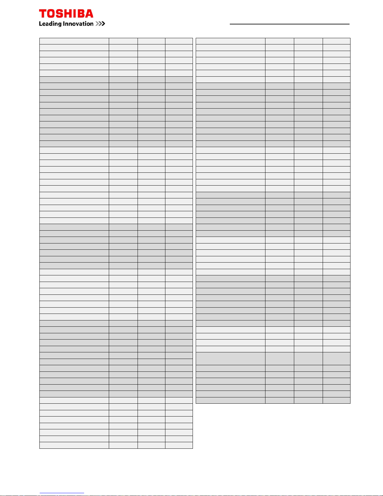
Acoustic Data
–
RAS Indoor Units
Page 5 of 78
RAS Indoor Units
Model
High
dB(A)
Med
dB(A)
Low
dB(A)
RAS-107SKV-E5
40 35 30
RAS-137SKV-E5
40 34 28
RAS-167SKV-E5
45 40 31
RAS-B10N3KVP-E 43 35 27
RAS-B13N3KVP-E 43 35 27
RAS-B16N3KVP-E
45 38 29
RAS-B10UFV-E
39 32 26
RAS-B13UFV-E
40 33 27
RAS-B18UFV-E 46 40 34
RAS-B10N3KV2-E
39 33 26
RAS-B13N3KV2-E
40 33 26
RAS-B16N3KV2-E
45 40 30
RAS-M10SMUV-E
37 33 30
RAS-M13SMUV-E 38 34 30
RAS-M16SMUV-E 40 37 31
The indoor unit is equipped with an automatic restart facility that allows the unit to restart, at the last set operating conditions, after a power
failure. The operation will resume without warning three minutes after power is restored.
This feature is not set up when these systems are shipped from the factory, therefore it will need to be activated by the installing company.
Generally the process is the same for all RAS products since approx 2001 and is as follows:
To initiate auto restart:
1. Turn the power on. Green On/Off light will flash.
2. Set the system to operate using the remote controller. Green On/Off light will be on constantly.
3. Press and hold down the temporary button for three seconds.
4. The indoor unit will bleep three times to acknowledge set up. In most cases the green light changes to orange.
5. The system will continue to operate during this set up.
6. After set up the system may be stopped using the remote controller.
To cancel auto restart:
1. The system is operating. Green On/Off light will be on constantly.
2. Stop the system operating using the remote controller. Green On/Off light will extinguish.
3. Press and hold down the temporary button for three seconds.
4. The indoor unit will bleep three times to acknowledge cancellation.
5. The system will have stopped operating.
This feature cannot be set if the timer is in operation.
The louver will not swing, if it was previously set, when the system auto restarts.
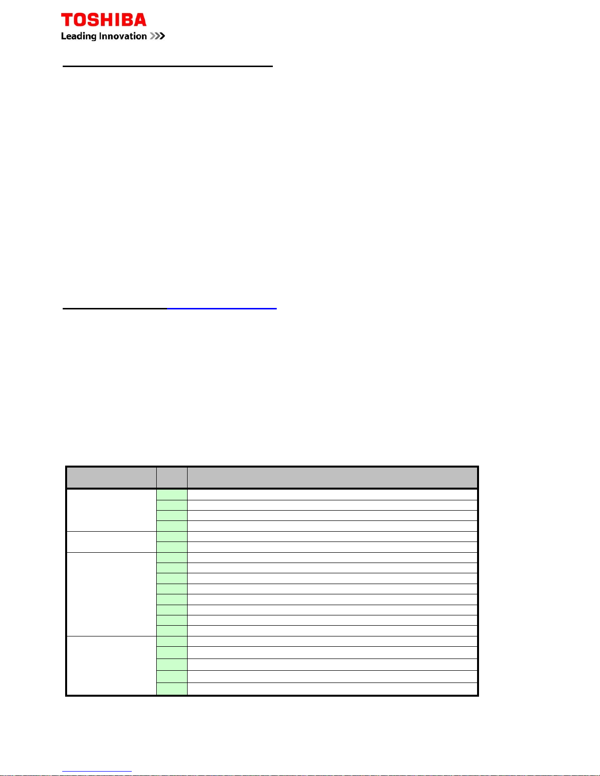
Fault Codes – RAS “N” Series
Do Not turn off the power supply before reading the fault codes, doing so will clear the diagnostic memory. Caution
must be taken when removing the access covers as high voltages are present.
Fault codes are displayed through the LEDs flashing at 5 times per second. Note, the green LED will flash once per
second when the system is initially powered.
More specific codes may be obtained, while in the fault mode through the wireless controller
1. Press CHK to enter service mode
2. Navigate through TIMER buttons until all LEDs flash, accompanied by the internal buzzer – compare the
displayed code with the table below
3. Press CLR button to clear the existing fault code (controller displays 7F)
4. Press ON/OFF button to exit service mode.
Initial
code/display
Code Description
01
0C
TA sensor open or short circuit
0d
TC sensor open or short circuit
11
Indoor fan motor problem
12
Indoor PCB problem
01
04
Indoor to outdoor communication (includes compressor thermostat)
05
Indoor to outdoor communication
02
14
Inverter low voltage or short circuit protection
16
Compressor position circuit
17
Compressor current detected during off-cycle
18
TE or TS sensor open or short circuit
19
Td sensor open or short circuit
1A
Outdoor fan motor problem
1b
TE sensor fault
1C
Compressor drive circuit
03
07
Indoor to outdoor communication (includes compressor thermostat)
08
Indoor heat exchanger changes temperature – but in wrong direction
1d
Compressor locked rotor current protection
1E
Compressor - high discharge temperature
1F
Compressor current remains too high – after current release
RAS – Auto Restart Function
Page 6 of 78
Page 7 of 78
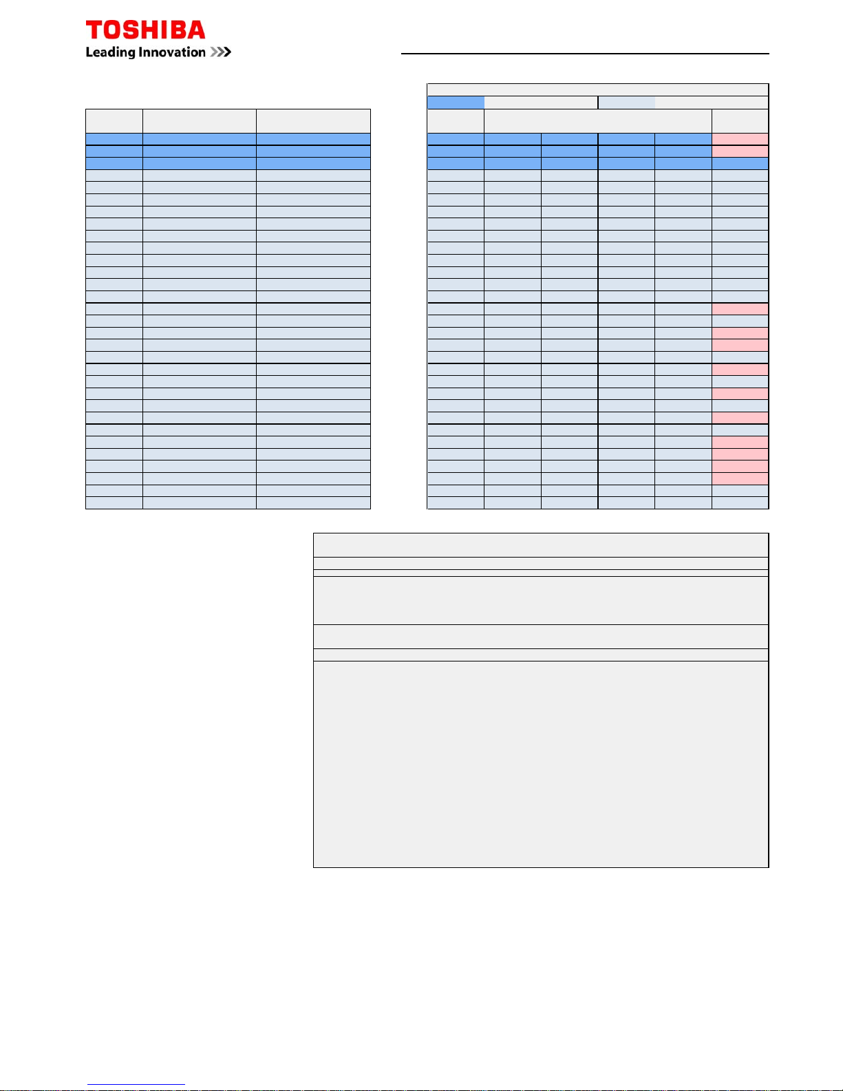
Mechanical Specifications - DI / SDI R410A Single Splits
Model
Pipe Sizes
Min/Max
Pipe Sep
(m)
Max
Height
Separation
Pre-
charge
(m)
Add
Charge
(g/m)
Base
Charge
(kg)
Dimensions
(mm)
Weight
(kg)
Liquid Suction
Commercial Range
RAV-SM564ATP-E
1/4 1/2
5/30
30
20
20 1.0 550x780x290 40
RAV-SM804ATP-E
3/8 5/8
40 1.7 550x780x290 44
RAV-SM1104ATP-E
5/50
30
40 2.8 890x900x320 68
RAV-SM1404ATP-E
40 2.8 890x900x320 68
RAV-SM1603AT-E
40 3.1 1340x900x320 99
RAV-SM2244AT8-E
1/2 1 1/8
7.5/70 80 5.9 1540x900x320 134
RAV-SM2804AT8-E
RAV-SP404ATP-E
1/4 1/2
5/30
20
20 1.0 550x780x290 40
RAV-SP564ATP-E
5/50
20 1.4 550x780x290 44
RAV-SP804ATP-E
3/8 5/8
30
40 2.1 890x900x320 63
RAV-SP1104AT-E
3/75
40 3.1 1340x900x320 93
RAV-SP1404AT-E
40 3.1 1340x900x320 93
RAV-SP1104AT8-E
3/75
40 3.1 1340x900x320 95
RAV-SP1404AT8-E
40 3.1 1340x900x320 95
RAV-SP1604AT8-E
40 3.1 1340x900x320 95
Performance & Electrical Specifications - DI / SDI R410A Single Splits
Model
Capacity kW
Ambient
Range °C
Energy
Rating
Cool/Heat
Phase
Power
To
Soft
Start
Max
Current
Suggested
Fuse Size
Interconnect
Cable
Cool Heat Cool Heat
Commercial Range
RAV-SM564ATP-E
5.00 5.30
46 to -15 15 to -15
A/A
1Ph + N
Outdoor Yes
8.95
16
3Core + Earth
RAV-SM804ATP-E
6.70 7.70 A/A 11.43 16
RAV-SM1104ATP-E
10.00 11.20 A/A 15.18
20
RAV-SM1404ATP-E
12.00 12.80
A/A
21.30 32
RAV-SM1603AT-E
14.00 16.00 B/A 23.90 32
RAV-SM2244AT8-E
20.00 22.40
46 to -20 15 to -20
D/B
3Ph + N
18.00 16
RAV-SM2804AT8-E
23.00 27.00
D/C
20.00 20
RAV-SP404ATP-E
3.60 4.00 43 to -15 15 to -15
A/A
1Ph + N
15.00 10
RAV-SP564ATP-E
5.30 5.60
43 to -15 15 to -20
A/A 13.30
16
RAV-SP804ATP-E
7.10 8.00 A/A 20.30
RAV-SP1104AT-E
10.00 11.20 A/A 20.50
RAV-SP1404AT-E
12.50 14.00 A/A 20.50 25
RAV-SP1104AT8-E
10.00 11.20
46 to -15 15 to -20
A/A
3Ph + N
14.70 10
RAV-SP1404AT8-E
12.50 14.00 A/A 14.70
16
RAV-SP1604AT8-E
14.00 16.00 B/A 14.70
Electrical Specifications - DI / SDI R410A Multi Splits
Page 8 of 78
Model Outdoor Twin Indoor Triple Indoor Quad Indoor Phase
Power
To
Suggested
Fused Size
Inter-
Connecting
Cable
RAV-SM80ATP-E RAV-SM40*T(P)-E
N/A N/A 1Ph-N Outdoor 16 3C+E
RAV-SM1104ATP-E RAV-SM56*T(P)-E N/A N/A
1Ph-N Outdoor 20 3C+E
RAV-SM1404ATP-E RAV-SM80*T(P)-E
N/A N/A 1Ph-N Outdoor 32 3C+E
RAV-SM1603AT-E RAV-SM80*T(P)-E RAV-SM56*T(P)-E
N/A 1Ph-N Outdoor 32 3C+E
RAV-SM2244AT8-E RAV-SM110*T(P)-E RAV-SM80*T(P)-E RAV-SM56*T(P)-E
3Ph-N Outdoor 16 3C+E
RAV-SM2244AT8-E RAV-SM110*T(P)-E RAV-SM80*T(P)-E RAV-SM56*T(P)-E
3Ph-N Outdoor 16 3C+E
RAV-SM2804AT8-E RAV-SM140*T(P)-E RAV-SM80*T(P)-E RAV-SM80*T(P)-E
3Ph-N Outdoor 20 3C+E
RAV-SM2804AT8-E RAV-SM140*T(P)-E RAV-SM80*T(P)-E RAV-SM80*T(P)-E
3Ph-N Outdoor 20 3C+E
RAV-SP804ATP-E RAV-SM40*T(P)-E
N/A N/A 1Ph-N Outdoor 16 3C+E
RAV-SP1104AT-E RAV-SM56*T(P)-E N/A N/A
1Ph-N Outdoor 16 3C+E
RAV-SP1104AT8-E RAV-SM56*T(P)-E
N/A N/A 3Ph-N Outdoor 10 3C+E
RAV-SP1404AT-E RAV-SM80*T(P)-E
N/A N/A 1Ph-N Outdoor 25 3C+E
RAV-SP1404AT8-E RAV-SM80*T(P)-E N/A N/A
3Ph-N Outdoor 16 3C+E
RAV-SP1604AT8-E RAV-SM80*T(P)-E RAV-SM56*T(P)-E
N/A 3Ph-N Outdoor 16 3C+E
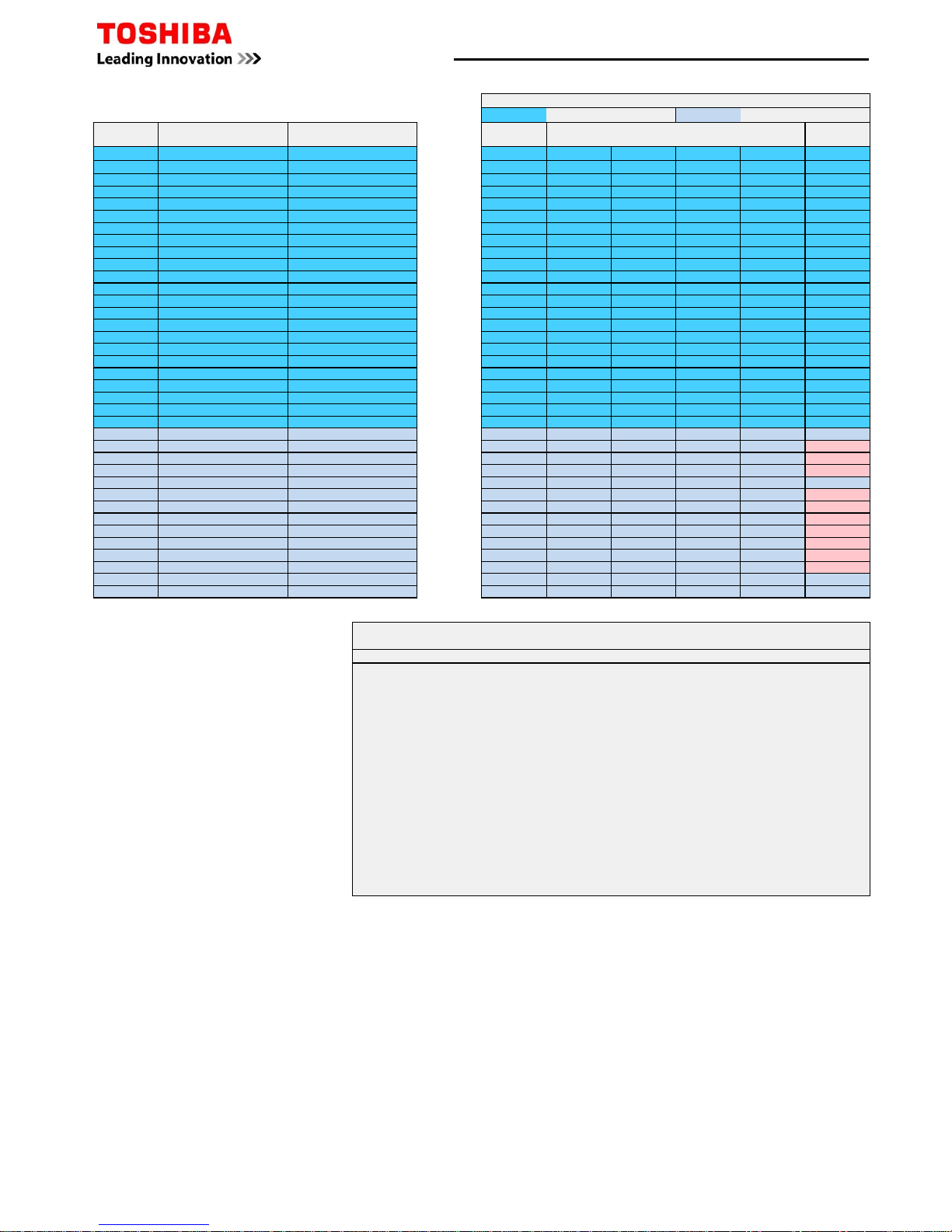
Acoustic Data – DI/SDI Indoor/Outdoor Units
Model Indoor
High
dB(A)
Med
dB(A)
Low
dB(A)
Model Indoor
High
dB(A)
Med
dB(A)
Low
dB(A)
RAV-SM562KRT-E
54 51 48
RAV-SM566BT-E
33 29 25
RAV-SM806KRT-E
60 56 51
RAV-SM806BT-E
34 30 26
RAV-SM564UTP-E
32 29 28
RAV-SM1106BT-E
40 36 33
RAV-SM804UTP-E
35 31 28
RAV-SM1406BT-E
40 36 33
RAV-SM1104UTP-E
58 53 48
RAV-SM1606BT-E
40 36 33
RAV-SM1404UTP-E
44 38 34
RAV-SM567CTP-E
37 35 28
RAV-SM1604UTP-E
45 40 36
RAV-SM807CTP-E
41 36 29
RAV-SM404MUT-E
55 51 46
RAV-SM1107CTP-E
44 38 32
RAV-SM564MUT-E
55 51 46
RAV-SM1407CTP-E
46 41 35
RAV-SM404SDT-E
39 36 33
RAV-SM1607CTP-E
46 41 35
RAV-SM564SDT-E
45 40 36
RAV-SM2242DT-E
54 - -
RAV-SM2802DT-E
55 - -
Model Outdoor
Cooling
dB(A)
Heating
dB(A)
Model Outdoor
Cooling
dB(A)
Heating
dB(A)
RAV-SM564ATP-E
46 48
RAV-SP404ATP-E
45 47
RAV-SM804ATP-E
48 52
RAV-SP564ATP-E
47 48
RAV-SM1104ATP-E
53 54
RAV-SP804ATP-E
48 49
RAV-SM1404ATP-E
54 55
RAV-SP1104AT-E
49 50
RAV-SM1603AT-E
51 53
RAV-SP1404AT-E
51 52
RAV-SM2244AT8-E
56 57
RAV-SP1104AT8-E
49 50
RAV-SM2804AT8-E
57 58
RAV-SP1404AT8-E
51 52
RAV-SP1604AT8-E
51 53
Page 9 of 78
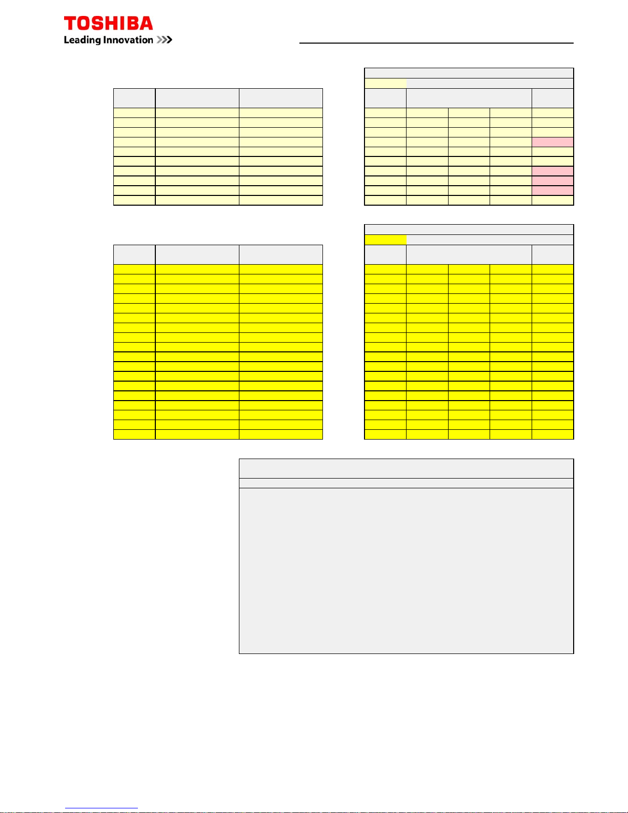
Mechanical & Electrical Data - Air-to-Air Heat Exchangers
Model
(Standard)
Power
Consumption
Low/High (W)
(L/H) Air
Volume
(m³/hr)
Static
Pressure
(Pa)
Dimensions Weight
(kg)
Duct
(mm)
1-ph+n
Fuse
Size
VN-M150HE 42 - 78 110 - 150 47 -102 900x900x290 36 100 3
VN-M250HE 52 - 138 155 - 250 28 - 98 900x900x290 36 150 3
VN-M350HE 82 - 182 210 - 350 65 -125 900x900x290 38 150 3
VN-M500HE 128 - 238 390 - 500 62 -150 1140x1140x350 53 200 3
VN-M650HE 178 - 290 520 - 650 61 -107 1140x1140x350 53 200 5
VN-M800HE 286 - 383 700 - 800 76 -158 1189x1189x400 70 250 5
VN-M1000HE 353 - 569 755 - 1000 84 -150 1189x1189x400 70 250 5
VN-M1500HE 570 - 786 1200 - 1500 112 -156 1189x1189x810 143 250 13
VN-M2000HE 702 - 1154 1400 - 2000 110 -143 1189x1189x810 143 250 13
Model
(DX Coil)
Capacity
Power
Consumption
Low/High (W
)
(L/H) Air
Volume
(m³/hr)
Static
Pressure
(Pa)
Dimensions Weight
(kg)
Duct
(mm)
1ph+n
Fuse
Size
Cool Heat
MMD-VN502HEXE 4.10 5.53
235 - 300 440 - 500 115 - 120 430x1140x1690 84 200 3
MMD-VN802HEXE 6.56 8.61 335 - 505 640 - 800 105 - 120 430x1189x1739 100 250 3
MMD-VN1002HEXE 8.25 10.90 485 - 550 820 - 950 105 - 135 430x1189x1739 101 250 3
Model
(DX Coil & Humidifier)
Capacity
Humidifier
(Kg/hr)
Power
Consumption
Low/High (W
)
(L/H) Air
Volume
(m³/hr)
Static
Pressure
(Pa)
Dimensions
Weight
(kg)
Duct
(mm)
1ph+n
Fuse
Size
Cool Heat
MMD-VNK502HEXE 4.10 5.53
3.0 240 - 305 440 - 500 85 - 95 430x1140x1690 91 200 3
MMD-VNK802HEXE 6.56 8.61 5.0 350 - 530 640 - 800 85 - 105 430x1189x1739
111 250 3
MMD-VNK1002HEXE 8.25 10.90 6.0 520 - 575 820 - 950 90 - 115 430x1189x1739
112 250 5
H x W* x D
H x W* x D
H x W* x D
* Width dimension excludes 200mm electrical box
Digital/Super Digital R410A Replacement Technology Refrigerant Pipe Sizing
Length Pre-charged Length Pre-charged Length Pre-charged Length Pre-charged Length Pre-charged
m m m m m m m m m m
SP40430203020302020102010
SP45430203020302020102010
SP5645020502020102010
DI Series 3
SM5635020502020102010
Length Pre-charged Length Pre-charged Length Pre-charged Length Pre-charged Length Pre-charged Length Pre-charged Length Pre-charged
m m m m m m m m m m m m m m
SP80430203020503050305030
SP11047530753025152515
SP14047530753025152515
SM804
202020203020302030
20
SM1104
50305030251525
15
SM1404
50305030251525
15
SM1604
50305030251525
15
Length Pre-charged Length Pre-charged Length Pre-charged Length Pre-charged
m m m m m m m m
SM2244
70307030502050
20
SM2804
70307030502050
20
Performance capacity is reduced due to the effect of gas pipe size being smaller than standard connection
Normal Pipe Sizes
Not Compatible
5/8 - 15.9 (1-size larger) 1/2 - 12.7 (STD) 5/8 - 15.9 (1-size larger)
1/4 - 6.4 (STD) 3/8 - 9.5 (1-size large)
3/8 - 9.5 (1-size smaller) 1/2 - 12.7 (STD)
1/2 - 12.7 (1-size smaller) 5/8 - 15.9 (STD) 1/2 - 12.7 (1-size smaller)
Maximum Pipe Distance
SDI Series 4
1/4 - 6.4 (1-size smaller) 3/8 - 9.5 (STD)
5/8 - 15.9 (STD) 3/4 - 19.1 (1-size larger) 5/8 - 15.9 (STD) 3/4 - 19.1 (1-size larger)
1/2 - 12.7 (1-size larger)
7/8 - 22.2 (1-size smaller) 1 1/8 - 28.6 (STD) 7/8 - 22.2 (1-size smaller) 1 1/8 - 28.6 (STD)
Maximum Pipe Distance
SDI Series 4
DI Series 4
Liquid Pipe Size inch" or mm 1/2 - 12.7 (STD) 5/8 - 15.9 (1-size larger)
SDI Series 4
Gas Pipe Size inch" or mm
Liquid Pipe Size inch" or mm
Liquid Pipe Size inch" or mm
Gas Pipe Size inch" or mm
Maximum Pipe Distance
Gas Pipe Size inch" or mm
Applicable Refrigerants
Existing Plant
R22
R407C
R417A
R404A
R134a
R12
Page 10 of 78
Digital / Super Digital Inverter Multi Split System Combinations
Page 11 of 78
Twin Split Systems
1 x Outdoor Unit
2 x Indoor Units
RAV-SM804ATP-E
RAV-SP804ATP-E
RA V - SM 4 04M UT -E
RA V - SM 4 04SDT -E
RA V - SM 4 06B T -E
RAV-SM1104ATP-E
RAV-SP1104AT-E
RAV-SP1104AT8-E
RA V - SM5 6 4 U T P-E
RA V - SM5 6 4 M U T -E
RA V - SM5 6 7 C T P-E
RA V - SM5 6 6 B T - E
RA V - SM5 6 4 S D T -E
RA V - SM5 6 6 K R T -E
RAV-SM1404ATP-E
RAV-SP1404AT-E
RAV-SP1404AT8-E
RAV-SM804UTP-E
RAV-SM807CTP-E
RAV-SM806BT-E
RAV-SM806KRT-E
RAV-SM1603AT-E
RAV-SP1604AT8-E
RA V - SM8 0 4 U T P-E
RA V - SM8 0 7 C T P-E
RA V - SM8 0 6 B T - E
RA V - SM8 0 6 K R T -E
RAV-SM2244AT8-E
RAV-SM1107CTP-E
RAV-SM1104UTP-E
RAV-SM1106BT-E
RAV-SM2804AT8-E
RAV-SM1407CTP-E
RAV-SM1404UTP-E
RAV-SM1406BT-E
Triple Split Systems
1 x Outdoor Unit
3 x Indoor Units
RAV-SM1603AT-E
RAV-SP1604AT8-E
RA V - SM 5 6 4 U T P- E
RA V - SM 5 6 4 MU T -E
RA V - SM 5 6 7 CT P- E
RA V - SM 5 6 6 B T -E
RA V - SM 5 6 4 SD T -E
RA V - SM 5 6 6 K R T -E
RAV-SM2244AT8-E
RA V - SM 8 0 4 U T P- E
RA V - SM 8 0 4 B T -E
RA V - SM 8 0 7 CT P- E
RA V - SM 8 0 6 K R T -E
RAV-SM2804AT8-E
RA V - SM 8 0 4 U T P- E
RA V - SM 8 0 6 B T -E
RA V - SM 8 0 7 CT P- E
RA V - SM 8 0 6 K R T -E
Quad Split Systems
1 x Outdoor Unit
4 x
Indoor Units
RAV-SM2244AT8-E
RA V - SM 5 6 4 U T P- E
RA V - SM 5 6 4 MU T -E
RA V - SM 5 6 7 CT P- E
RA V - SM 5 6 6 B T -E
RA V - SM 5 6 4 SD T -E
RA V - SM 5 6 6 K R T -E
RAV-SM2804AT8-E
RA V - SM 8 0 4 U T P- E
RA V - SM 8 0 7 CT P- E
RA V - SM 8 0 6 B T -E
RA V - SM 8 0 6 K R T -E
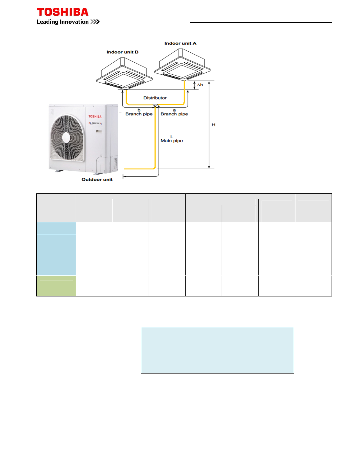
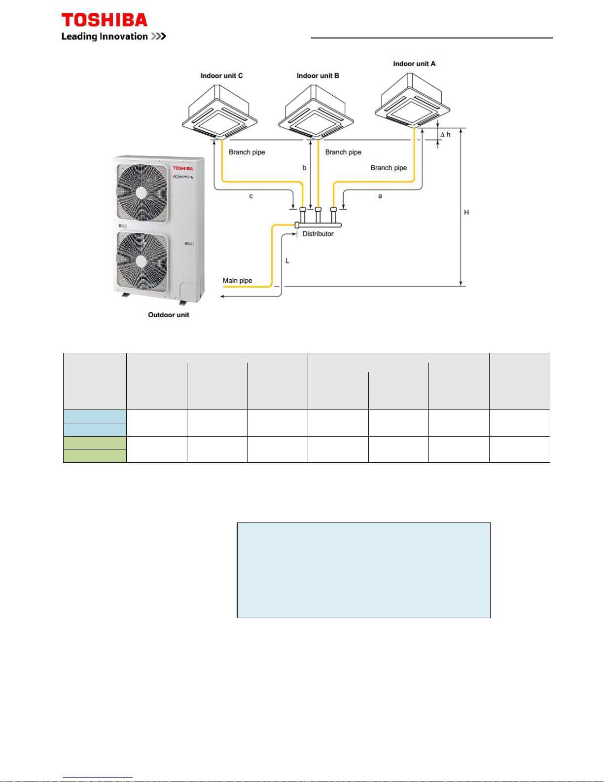
Pipe Specifications
*
Total length of pipe between furthest indoor and outdoor unit.
†
Maximum distance of Branch pipe from main pipe distributor to furthest indoor unit.
‡
Maximum subtractive distance between pipe branches. Example: -
Example 1
Installed length main pipe L to distributor=38m
Installed length branch a=12m
Installed length branch b=10m
Example 2
Installed length main pipe L to distributor=40m
Installed length branch a=14m
Installed length branch b=2m
Example 1
Total pipe length L + a 38 + 12= 50m
Subtractive pipe length a – b 12 - 10= 2m
Example 2
Total pipe length L + a 40 + 14= 64m
Subtractive pipe length a – b 14 - 2= 12m
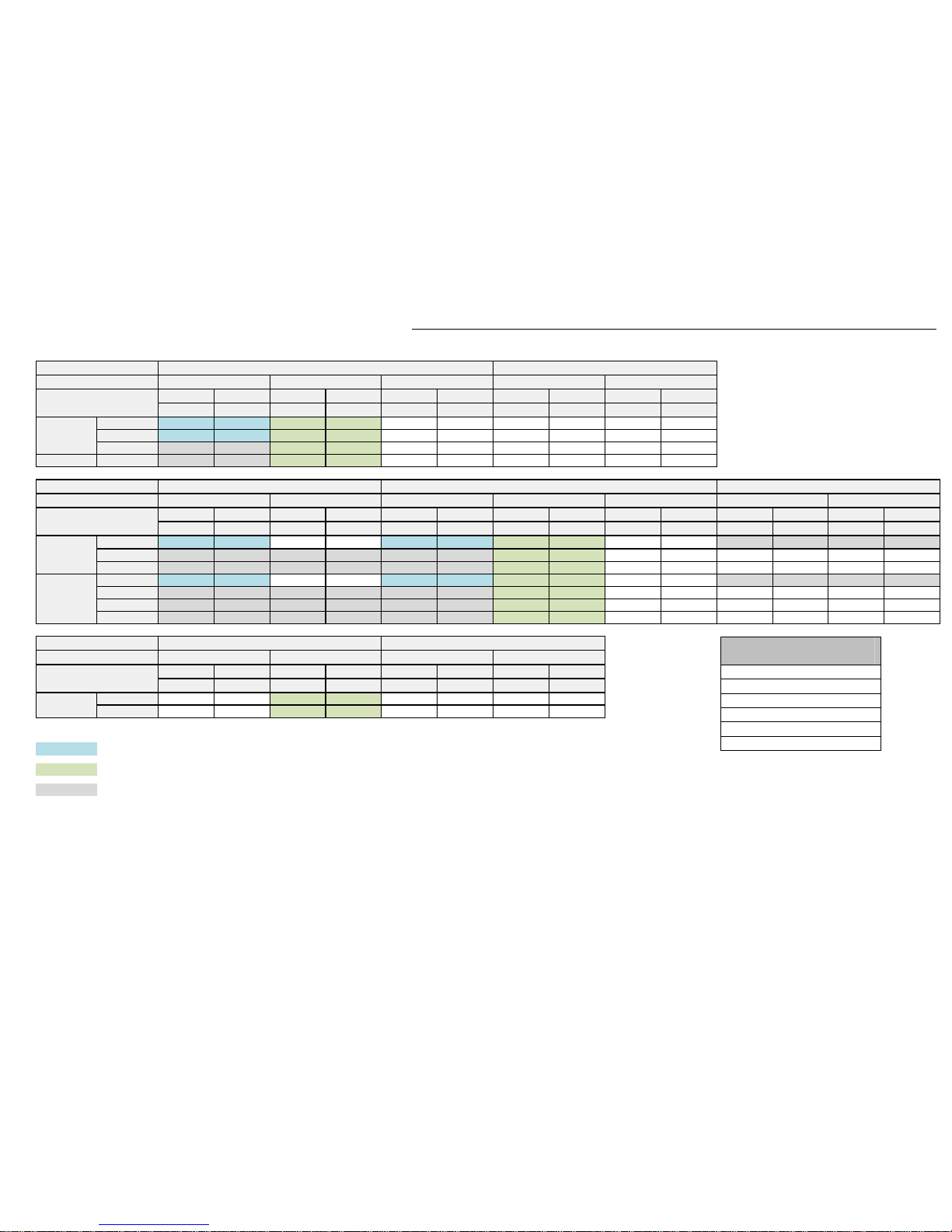
Digital / Super Digital Inverter Twin Splits
Model
(RAV-)
Allowable Piping Length (m)
Height Difference
(m)
Number of
Bent Portions
Maximum
or Less
*Total Length
(L+a or L+b)
Maximum
†Branch Piping
a or b to
Furthest Indoor
Maximum
‡Subtractive
Piping Length
a-b or b-a
Maximum
Indoor Unit
-
Outdoor Unit (H)
Indoor Unit
Height
Difference (Δh)
Maximum
Outdoor Unit
Higher
Maximum
Indoor Unit
Higher
Maximum
SM804ATP-E 30 10 5 30 30 0.5 10
SM1104ATP-E
SM1404ATP-E
SM1603AT-E
SP804ATP-E
SP1104AT(8)-E
SP1404AT(8)-E
SP1604AT8-E
50 15 10 30 30 0.5 10
SM2244AT8-E
SM2804AT8-E
70 20 10 30 30 0.5 10
Page 12 of 78
Example 3
Installed length main pipe L to distributor=50m
Installed length branch a=12m
Installed length branch b=10m
Example 4
Installed length main pipe L to distributor=60m
Installed length branch a=14m
Installed length branch b=2m
Additional Charge
Example 1
Installed length main pipe L to distributor=38m
Installed length branch a=12m
Installed length branch b=10m
Model
(RAV-)
Main Pipes Branch Pipes
Sizes (“)
Gas/Liquid
Pre-charge (m)
Add Amount
(kg/m) – [ ]
Sizes (“)
Gas/Liquid
Pre-charge (m)
Add Amount
(kg/m) – [ ß ]
SM804ATP-E
5/8 - 3/8 18 0.040 1/2 - 1/4 2 0.020
SP804ATP-E
SM1104ATP-E
5/8 - 3/8 18 0.040 1/2 - 1/4 2 0.020
SP1104AT(8)-E
SM1404ATP-E
5/8 - 3/8 18 0.040 5/8 - 3/8 2 0.040
SP1404AT(8)-E
SM1603AT-E
5/8 - 3/8 28 0.040 5/8 - 3/8 2 0.040
SP1604AT8-E
SM2244AT8-E
1 1/8 - 1/2 28 0.080 5/8 - 3/8 4 0.040
SM2804AT8-E
Gas calculation - [Main pipe] (L-18) x + [Branch Pipe] (a+b - 4) x ß = additional charge
Gas calculation - [Main pipe] (L-28) x + [Branch Pipe] (a+b - 4) x ß= additional charge
Example 1 using SM1104ATP-E
Total pipe length L - 18 x
38 - 18 =20 x 0.040= 0.80 +
Branch pipe length a + b x ß 12 + 10 - 4 =18 x 0.020= 0.36
Add Amount 1.16 kg
Example 3
Total pipe length L + a 50 + 12= 62m
Subtractive pipe length a – b 12 - 10= 2m
Example 4
Total pipe length L + a 60 + 14= 74m
Subtractive pipe length a – b 14 - 2= 12m
Example 1 using SM2804AT8-E
Total pipe length L - 28 x
38 - 28 =10 x 0.080= 0.80 +
Branch pipe length a + b x ß 12 + 10 - 4 =18 x 0.040= 0.72
Add Amount 1.52 kg
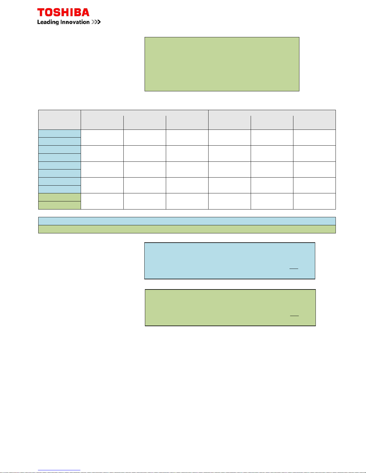
Page 13 of 78
Factor
Factor
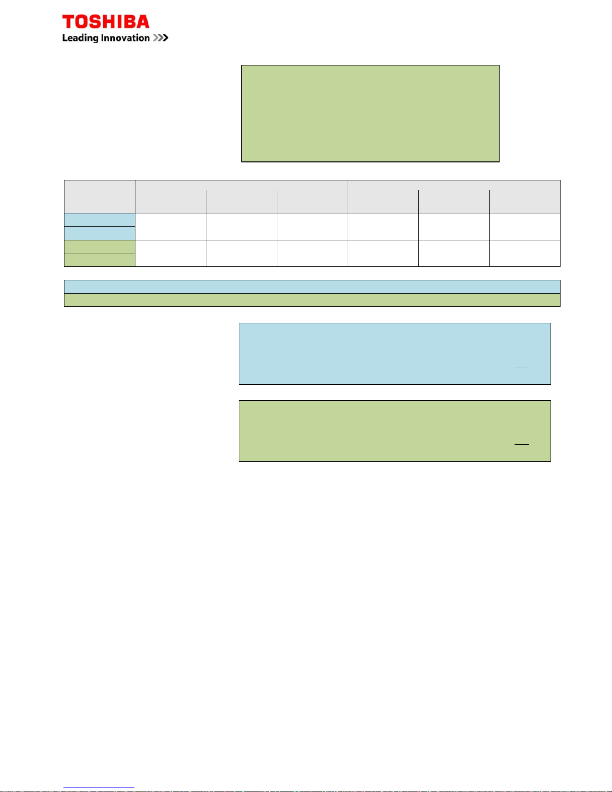
Pipe Specifications
Model (RAV-)
Allowable Piping Lengths (m) Height Difference (m)
Number of
Bent portions
Maximum
or Less
*
Total Length
La + Lb
La + Lc
Maximum
†
Branch Piping
La, Lb or Lc to
Furthest Indoor
Maximum
‡
Subtractive
Piping Length
Lb - La
Lb - Lc
Maximum
Indoor Unit - Outdoor Unit (H)
Indoor Unit
Height
Difference (∆h)
Maximum
Outdoor Unit
Higher
Maximum
Indoor Unit
Higher
Maximum
SM1603AT-E
50 15 10 30 30 0.5 10
SP1604AT8-E
SM2244AT8-E
70 20 10 30 30 0.5 10
SM2804AT8-E
*
Total length of pipe between furthest indoor and outdoor unit.
†
Maximum distance of Branch pipe from main pipe distributor to furthest indoor unit.
‡
Maximum subtractive distance between pipe branches. Example: -
Example 1
Installed length main pipe L to distributor=38m
Installed length branch a=12m
Installed length branch b=10m
Installed length branch c=12m
Example 2
Installed length main pipe L to distributor=40m
Installed length branch a=15m
Installed length branch b=4m
Installed length branch c=12m
Example 1
Total pipe length L + a 38 + 12= 50m
Subtractive pipe length a – b 12 - 10= 2m
Subtractive pipe length c – b 12 - 10= 2m
Example 2
Total pipe length L + a 40 + 15= 55m
Subtractive pipe length a – b 15 - 4= 11m
Subtractive pipe length c – b 12 - 4= 8m
Digital / Super Digital Inverter Triple Splits
Page 14 of 78
Example 3
Installed length main pipe L to distributor=40m
Installed length branch a=12m
Installed length branch b=12m
Installed length branch c=10m
Example 4
Installed length main pipe L to distributor=50m
Installed length branch a=20m
Installed length branch b=3m
Installed length branch c=5m
Additional Charge
Model (RAV-)
Main Pipes Branch Pipes
Sizes (“)
Gas/Liquid
Pre-charge (m)
Add Amount
(kg/m) – [ ]
Sizes (“)
Gas/Liquid
Pre-charge (m)
Add Amount
(g/m) – [ ß ]
SM1603AT-E
5/8 – 3/8 28 0.040 5/8 – 3/8
6 0.040
SP1604AT8-E
SM2244AT8-E
1 1/8 – 1/2 28 0.080 5/8 – 3/8 6 0.040
SM2804AT8-E
Gas calculation - [Main pipe] (L-28) x + [Branch Pipe] (a+b+c - 6) x ß = additional charge
Gas calculation - [Main pipe] (L-28) x + [Branch Pipe] (a+b+c - 6) x ß= additional charge
Example 1
Installed length main pipe L to distributor=38m
Installed length branch a=12m
Installed length branch b=10m
Installed length branch c=12m
Example 3
Total pipe length L + a 40 + 12= 52m
Subtractive pipe length a – b 12 - 12= 0m
Subtractive pipe length c – b 12 - 10= 2m
Example 4
Total pipe length L + a 50 + 20= 70m
Subtractive pipe length a – b 20 - 3= 15m
Subtractive pipe length c – b 5 - 3= 2m
Example 1 above using SM1603AT-E
Total pipe length L - 28 x
38 - 28 =10 x 0.040= 0.40 +
Branch pipe length a + b + c x ß 12+10+ 12- 6 =28 x 0.040= 1.12
Add Amount 1.52 kg
Example 1 above using SM2804AT8-E
Total pipe length L - 28 x
38 - 18 =20 x 0.080= 0.80 +
Branch pipe length a + b + c x ß 12+10+ 12- 6 =28 x 0.040= 1.12
Add Amount 1.92 kg
Page 15 of 78
Factor
Factor
Example 1
Total pipe length L + b + c 20 + 10 + 5= 35m
Branch length b + d 10 + 5= 15m
Branch length a + e 10 + 5= 15m
Branch length a + f 10 + 5= 15m
Subtractive pipe length c+b - d+b 5+10 - 5+10= 0m
Subtractive pipe length c+b - e+a 5+10 - 5+10= 0m
Subtractive pipe length c+b - f+a 5+10 - 5+10= 0m
Subtractive pipe length d+b - e+a 5+10 - 5+10= 0m
Subtractive pipe length d+b - f+a 5+10 - 5+10= 0m
Subtractive pipe length e+a - f+a 5+10 - 5+10= 0m
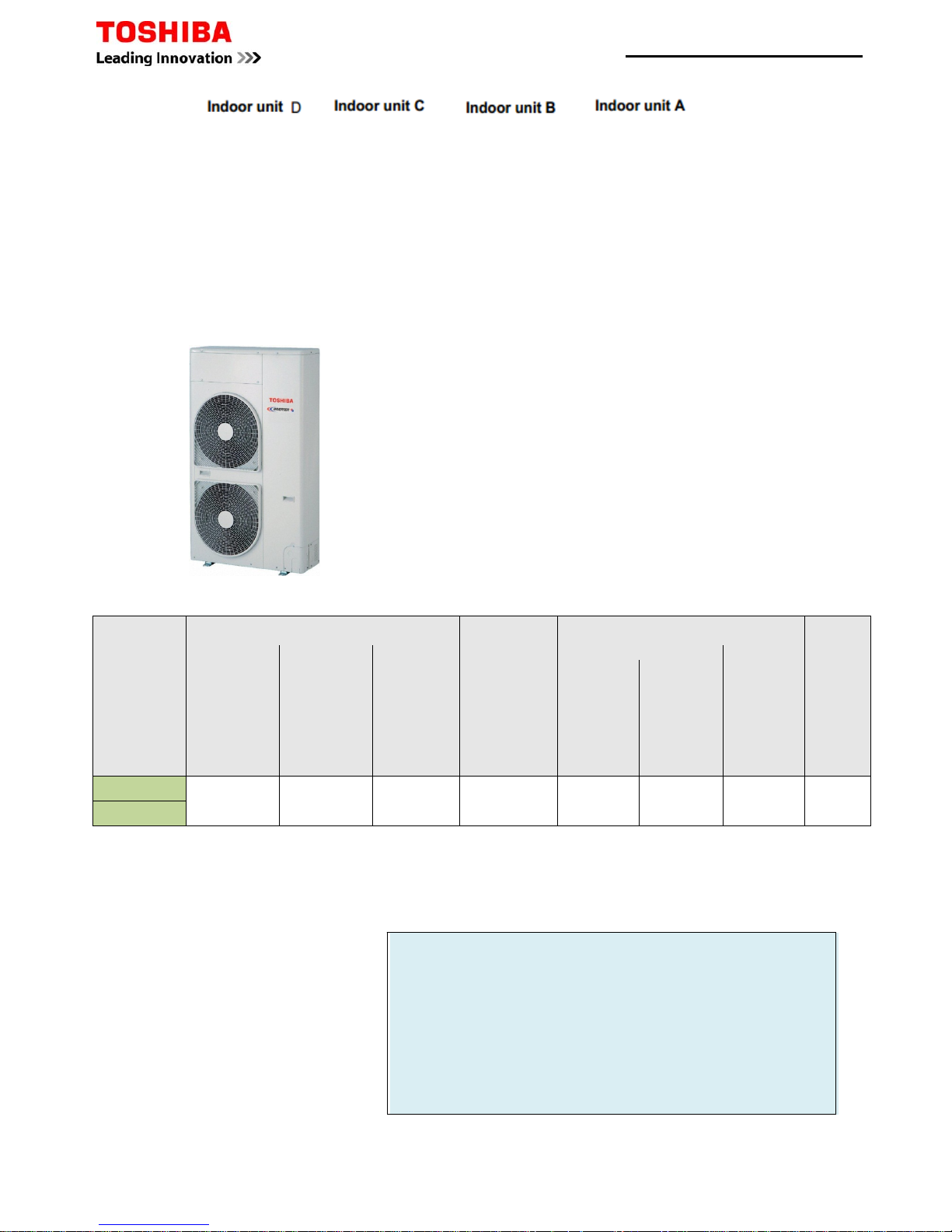
Pipe Specifications
Model (RAV-)
Allowable Piping Lengths (m)
Height Difference (m)
Number of
Bent
portions
Maximum
or Less
*
Total Length
(L+b+c) or
(L+b+d) or
(L+a+e) or
(L+a+f)
Maximum
†
Branch Piping
c, d, e & f to
Furthest Indoor
Maximum
¥Branch Piping
b+c
b+d
a+e
a+f
Maximum
‡
Subtractive
Branch Piping
(c+b) - (d+b)
(c+b) - (e+a)
(c+b) - (f+a)
(d+b) - (e+a)
(d+b) - (f+a)
(e+a) - (f+a)
Maximum
Outdoor Unit-Indoor Unit(H)
Indoor unit
height
difference
(∆h)
Maximum
Outdoor Unit
higher
Maximum
Indoor Unit
higher
Maximum
SM2244AT8-E
70 15 20 6 30 30 0.5 10
SM2804AT8-E
*
Total length of pipe between furthest indoor and outdoor unit.
†
Maximum distance of Branch pipe from main pipe distributor to furthest indoor unit.
¥ Maximum pipe distance between Branched pairs
‡
Maximum subtractive distance between pipe branches. Example:
Example 1
Installed length main pipe L to distributor=20m
Installed length branch b=10m
Installed length branch c=5m
Installed length branch d=5m
Installed length branch a=10m
Installed length branch e=5m
Installed length branch f=5m
Digital Inverter Quad Splits
Page 16 of 78
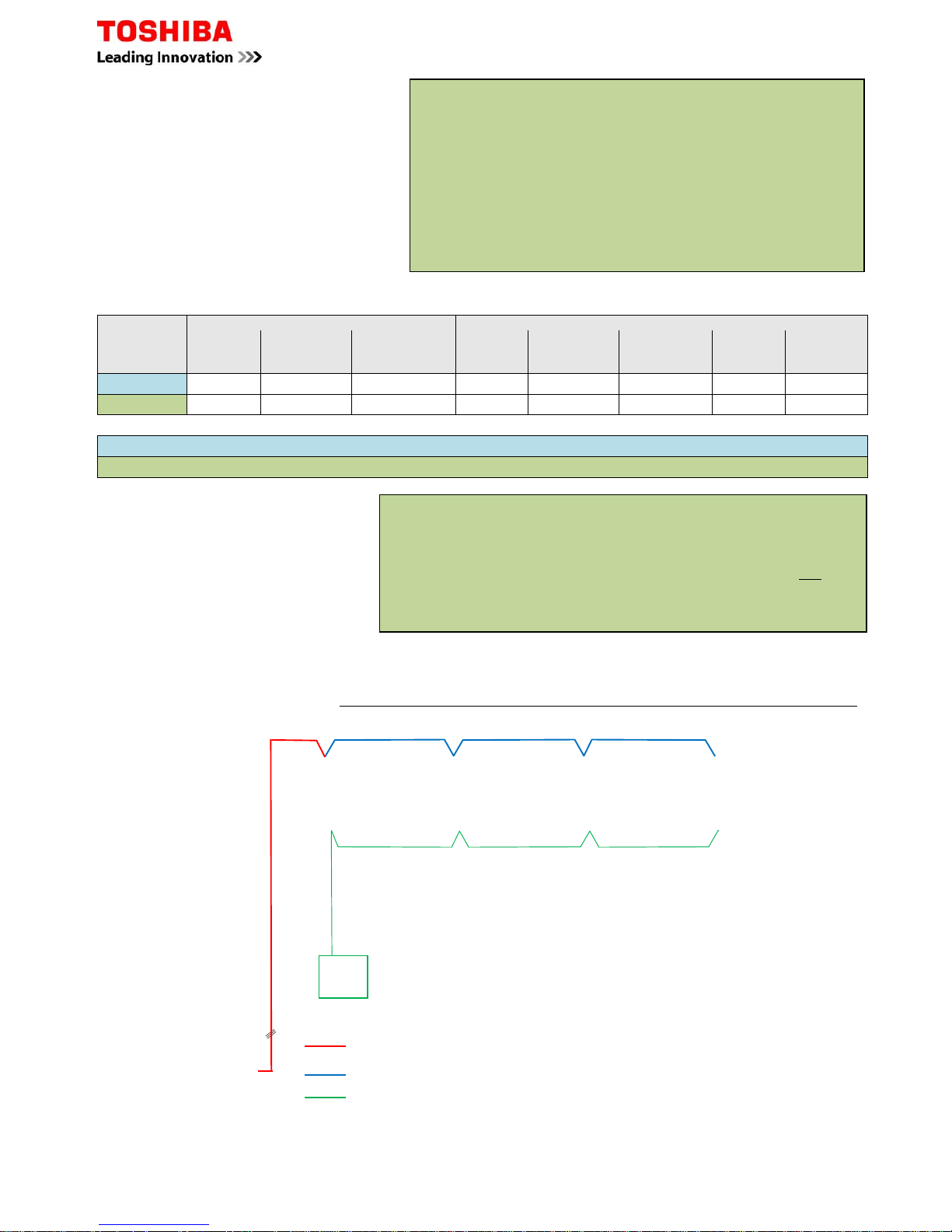
Page 17 of 78
Interconnecting Cables
3 Core+Earth Power connected to terminals
2 Core+Earth Power connected to terminals
2 Core Control connected to terminals A + B
Example 2
Total pipe length L + b + c 50+ 15+ 10 = 75m
Branch length b + c 15+ 10 = 25m
Branch length b + d 15+ 6 = 21m
Branch length a + e 15+ 5 = 20m
Branch length a + f 15+ 10 = 25m
Subtractive pipe length c+b - d+b 10+ 15- 6+ 15 = 4m
Subtractive pipe length c+b - e+a 10+ 15- 5+ 15 = 5m
Subtractive pipe length c+b - f+a 10+ 15- 10+ 15 = 0m
Subtractive pipe length d+b - e+a 6+ 15- 5+ 15 = 1m
Subtractive pipe length d+b - f+a 6+ 15- 10+ 15 = 1m
Subtractive pipe length e+a - f+a 6+ 15- 10+ 15 = 1m
Example 2
Installed length main pipe L to distributor=50m
Installed length branch b=15m
Installed length branch c=10m
Installed length branch d=6m
Installed length branch a=15m
Installed length branch e=5m
Installed length branch f=10m
Additional Charge
Example 1
Installed length main pipe L to distributor=20m
Installed length branch b=10m
Installed length branch c=5m
Installed length branch d=5m
Installed length branch a=10m
Installed length branch e=5m
Installed length branch f=5m
Model
Main Pipes Branch pipes
Sizes (“)
Gas/Liquid
Pre-charge (m) Add amount
(kg/m) – []
Sizes (“)
Gas/Liquid
Pre-charge (m) Add amount
(g/m) – [ß]
Sizes (“)
Gas/Liquid
Add amount
(g/m) – [γ]
SM2244AT8-E 1 1/8 – 1/2 28 0.080 5/8 – 3/8 4 0.040 1/2 – 1/4 0.020
SM2804AT8-E 1 1/8 – 1/2 28 0.080 5/8 – 3/8 4 0.040 5/8 – 3/8 0.040
Gas calculation - [Main pipe] (L-28) x + [Branch Pipe] (a + b - 4) x ß + (c+d+e+f) x
γ
= additional charge
Gas calculation - [Main pipe] (L-28) x + [Branch Pipe] (a + b - 4) x ß + (c+d+e+f) x
γ
= additional charge
Example 1 using SM2804AT8-E
Total pipe length L - 28 x
20 - 28 =-8 x 0.080= -0.64 +
Branch pipe length a + b 4 x ß 10+10- 4 =16 x 0.040= 0.64 +
Branch pipe length c + d + e + f x
γ 5+5+5+5 =20 x 0.040= 0.80
Add Amount 0.80 kg
Configuration same for Twin, Triple & Quad combinations.
A common controller will be used, individual controls is not possible.
Master to Slave power supply.
Indoor Unit B
Indoor Unit CIndoor Unit D
Indoor Unit A
Remote
Controller
Digital / Super Digital Multi Split System Wiring Schematic
Factor
Factor
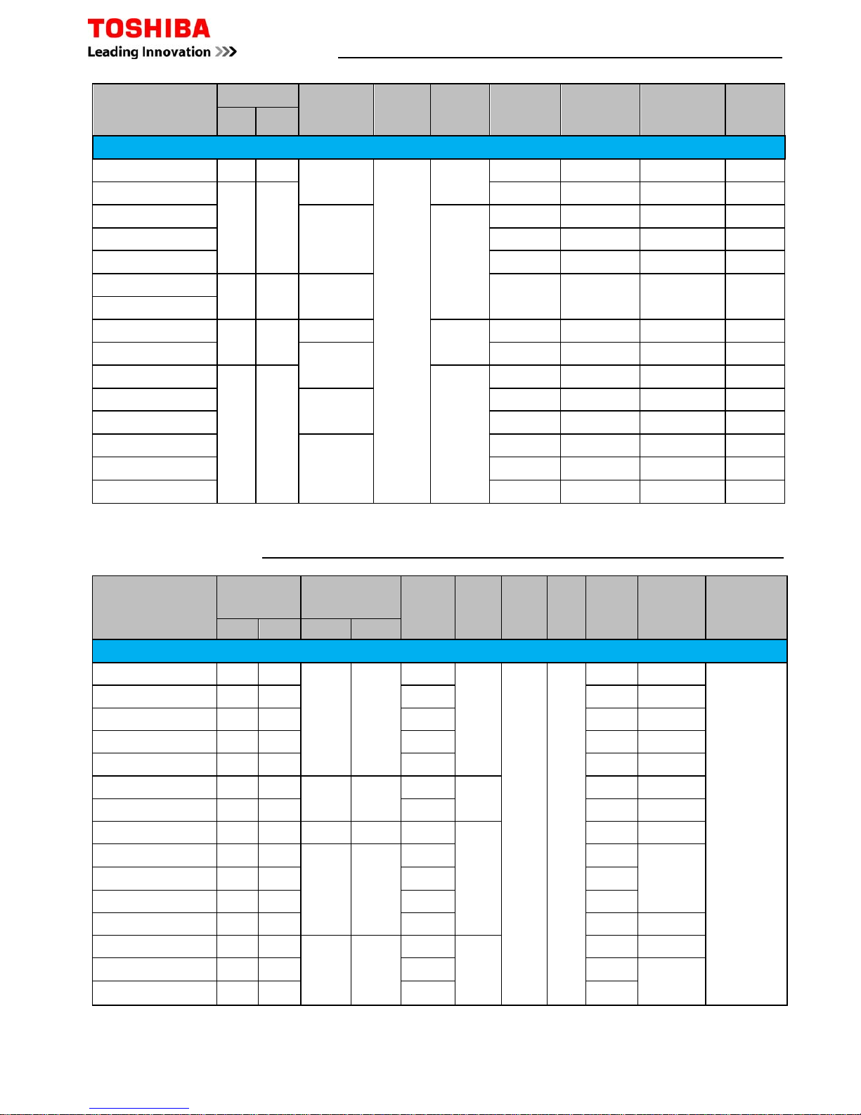
VRF System Make Up Chart
Model
Reference
MMY
Duty
HP
Cooling
Capacity
kW
Heating
Capacity
kW
Outdoor Unit Combination
Max.
Indoor
Units
0401 0501 0601 0804 1004 1204 1404 1604
Mini SMMS MCY
MAP0401HT
4
12.1
12.516
MAP0501HT 5 14.0 16.0 1 8
MAP0601HT 6 15.5 18.0 1 9
Note:- MAP0401HT, MAP0501HT & MAP601HT are
NOT
Modular
SMMSiHeat Pump MMY
MAP0501HT8-E 5 14.0 16.0 1 1 8
MAP0601HT8-E 6 16.0 18.0 10
MAP0804HT8-E 8 22.4 25.0 1 13
MAP1004HT8-E 10 28.0 31.5 1 16
MAP1204HT8-E 12 33.5 37.5 1 20
MAP1404HT8-E 14 40.0 45.0 1 23
MAP1604HT8-E 16 45.0 50.0 1 27
AP1814HT8-E 18 50.4 56.5 1 1 30
AP2014HT8-E 20 56.0 63.0 2 33
AP2214HT8-E 22 61.5 69.0 1 1 37
AP2414HT8-E 24 68.0 76.5 2 40
AP2614HT8E
26
73.0
81.511
43
AP2814HT8-E 28 78.5 88.0 1 1 47
AP3014HT8-E 30 85.0 95.0 1 1 48
AP3214HT8-E 32 90.0 100.0 2 48
AP3414HT8E
34
96.0
108.0
1248
AP3614HT8-E 36 101.0 113.0 3 48
AP3814HT8E
38
106.5
119.5
111
48
AP4014HT8-E 40 112.0 127.0 2 1 48
AP4214HT8-E 42 118.0 132.0 1 1 1 48
AP4414HT8-E 44 123.5 138.0 1 2 48
AP4614HT8-E 46 130.0 145.0 1 2 48
AP4814HT8-E 48 135.0 150.0 3 48
SMMSiHigh Efficiency Heat Pump MMY
AP1624HT8-E 16 45.0 50.0 2 27
AP2424HT8-E 24 68.0 76.5 3 40
AP2624HT8-E 26 73.0 81.5 2 1 43
AP2824HT8-E 28 78.5 88.0 1 2 47
AP3024HT8-E 30 85.0 95.0 3 48
AP3224HT8-E 32 90.0 100.0 4 48
AP3424HT8-E 34 96.0 108.0 3 1 48
AP3624HT8-E 36 101.0 113.0 2 2 48
AP3824HT8-E 38 106.5 119.5 1 3 48
AP4024HT8-E 40 112.0 126.5 4 48
AP4224HT8-E 42 118.0 132.0 3 1 48
AP4424HT8-E 44 123.5 138.0 2 2 48
AP4624HT8-E 46 130.0 145.0 1 3 48
AP4824HT8-E 48 135.0 150.0 4 48
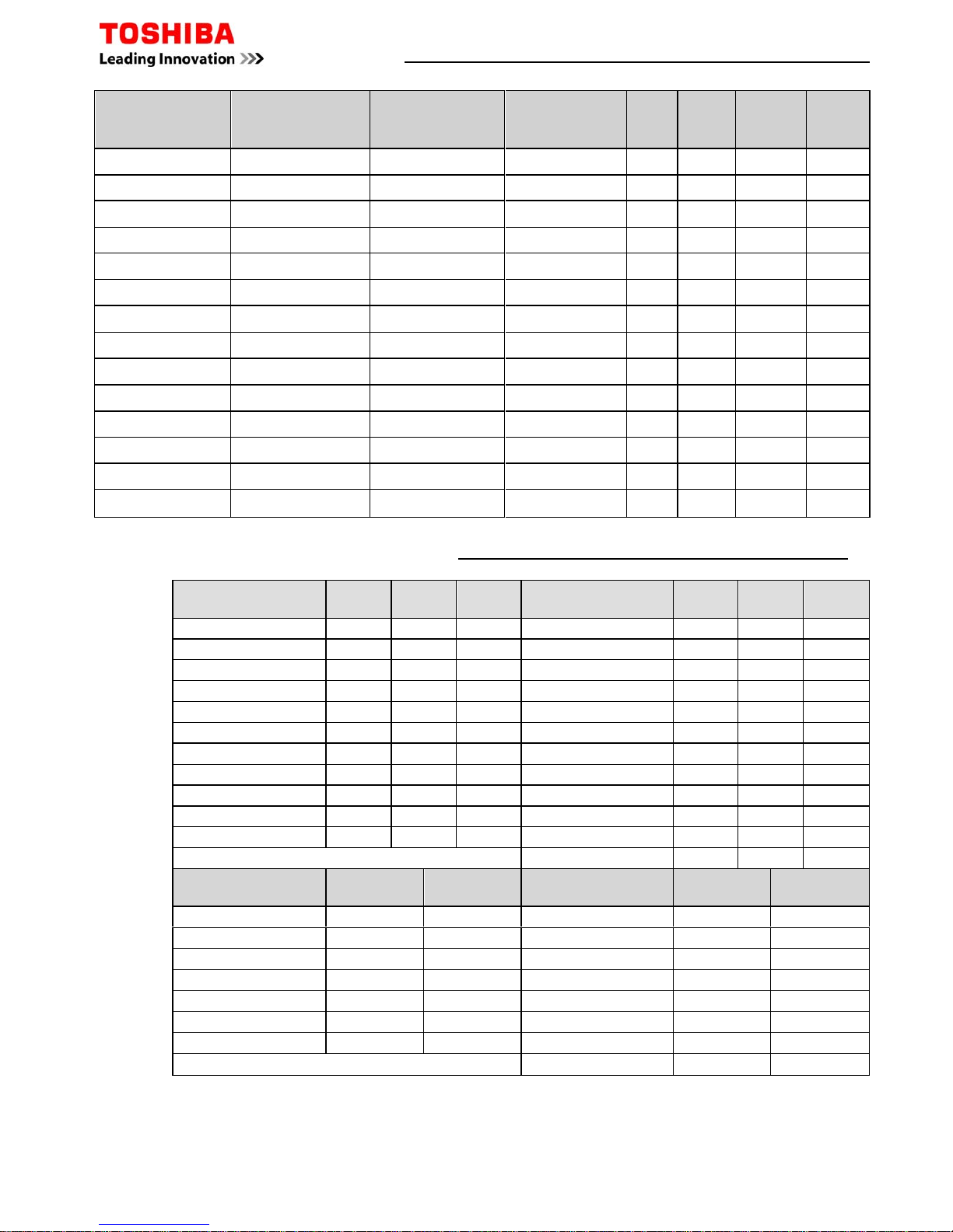
SHRMiHeat Recovery MMY
Model
Reference
MMY
Duty
HP
Cooling
Capacity
Kw
Heating
Capacity
kW
Outdoor Unit Combination
Max.
Indoor
Units
0804 1004 1204 1404
MAP0804FT8-E 8 22.4 25.0 1 13
MAP1004FT8-E 10 28.0 31.5 1 16
MAP1204FT8-E 12 33.5 37.5 1 20
MAP1404FT8-E 14 40.0 45.0 1 23
AP1614FT8-E 16 45.0 50.0 2 27
AP1814FT8-E 18 50.4 56.5 1 1 30
AP2014FT8-E 20 56.0 63.0 2 33
AP2214FT8-E 22 61.5 69.0 1 1 37
AP2414FT8-E 24 68.0 76.5 1 1 40
AP2614FT8-E 26 73.0 81.5 1 1 43
AP2814FT8-E 28 78.5 88.0 2 47
AP3014FT8-E 30 85.0 95.0 3 48
AP3214FT8-E 32 90.0 100.0 2 1 48
AP3414FT8-E 34 96.0 108.0 2 1 48
AP3614FT8-E 36 101.0 113.0 3 48
AP3814FT8-E 38 106.5 119.5 2 1 48
AP4014FT8-E 40 112.0 127.0 1 2 48
AP4214FT8-E 42 118.0 132.0 3 48
Page 18 of 78

Electrical Data – VRF Outdoor Units
Model (Outdoor) HP Phase
Power
To
Soft
Start
Suggested
Fuse Size
Fuse
Type
Inter-Connecting
Cable
Mini SMMS
MCY-MAP0401HT 4 1Ph-N
Indoor + Outdoor
Y 20 C 2C Screened
MCY-MAP0501HT 5 1Ph-N
Indoor + Outdoor
Y 25 C 2C Screened
MCY-MAP0601HT 6 1Ph-N
Indoor + Outdoor
Y 32 C 2C Screened
SMMS
MMY-MAP0501HT8-E 5 3Ph-N Indoor + Outdoor Y 16 C 2C Screened
MMY-MAP0601HT8-E 6 3Ph-N
Indoor + Outdoor
Y 16
C
2C Screened
SMMS
i
MMY-MAP0804HT8-E 8 3Ph-N
Indoor + Outdoor
Y 16 C 2C Screened
MMY-MAP1004HT8-E 10 3Ph-N Indoor + Outdoor Y 16 C 2C Screened
MMY-MAP1204HT8-E 12 3Ph-N
Indoor + Outdoor
Y 25 C 2C Screened
MMY-MAP1404HT8-E 14 3Ph-N
Indoor + Outdoor
Y 25 C 2C Screened
MMY-MAP1604HT8-E 16 3Ph-N
Indoor + Outdoor
Y 32 C 2C Screened
SHRM
i
MMY-MAP0804FT8-E 8 3Ph-N
Indoor + Outdoor
Y 16 C 2C Screened
MMY-MAP1004FT8-E 10 3Ph-N
Indoor + Outdoor
Y 20 C 2C Screened
MMY-MAP1204FT8-E 12 3Ph-N
Indoor + Outdoor
Y 20 C 2C Screened
MMY-MAP1404FT8-E 14 3Ph-N
Indoor + Outdoor
Y 25 C 2C Screened
VRF Additional Refrigerant Charge Amount
Indoor Unit
Model
Capacity
Code HP
Capacity
Code kW
007 0.8
2.2
009 1
2.8
012 1.25
3.6
015 1.7
4.5
018 2
5.6
024 2.5
7.1
027 3
8.0
030 3.2
9.0
036 4
11.2
048 5
14.0
056 6
16.0
072 8
22.4
096 10
28.0
Capacity Data – VRF Indoor Units
Liquid
SMMS SHRM
Pipe Size
Mini SMMS
SMMS
i
SHRM
i
inch" - mm kg/m kg/m kg/m
1/4 - 6.4 0.025 0.025 0.0325
3/8 - 9.5 0.055 0.055 0.0715
1/2 - 12.7 0.105 0.1365
5/8 - 15.9 0.160 0.2080
3/4 - 19.1 0.250 0.3250
7/8 - 22.2 0.350 0.4550
Additonal Refrigerant Charge Amount
Page 19 of 78
VRF Additional Refrigerant Charge Calculations
Page 20 of 78
Correction
1 2 3 4 Factor kg
4 4 4 -0.8
5 5 5 -0.4
6 6 6 0
5 5 5 0
6 6 6 0
8 8 8 1.5
10 10 10 2.5
12 12 12 3.5
14 14 8 6 0
16 16 8 8 0
18 18 10 8 0
20 20 10 10 3
22 22 8 8 6 0
22 22 12 10 5
24 24 8 8 8 -4
24 24 12 12 7
26 26 10 8 8 -4
28 28 10 10 8 -2
30 30 10 10 10 0
32 32 8 8 8 8 -6
32 32 12 10 10 1
34 34 10 8 8 8 -6
34 34 12 12 10 3
36 36 10 10 8 8 -6
36 36 12 12 12 4
38 38 10 10 10 8 -6
40 40 10 10 10 10 -5
42 42 12 10 10 10 -4
44 44 12 12 10 10 -2
46 46 12 12 12 10 0
48 48 12 12 12 12 2
Refrigerant
Length
0.0250 x =
0.0550 x =
Additional amount of refrigerant =
Refrigerant
Length
0.025 x =
0.055 x =
0.105 x =
0.160 x =
0.250 x =
0.350 x =
Additional amount of refrigerant =
Total System Charge =
Base Charge + Additional Refrigerant Charge + HP Correction Factor
HP
MAP0501HT8-E
MAP0601HT8-E
SMMS
12.5
12.5
Base Charge kg
Trim Charge
Mini SMMS
SMMS
Condenser Combinations
HP
MAP1001HT8-E
AP3001HT8-E
AP3201HT8-E
AP3211HT8-E
kg
kg
MAP0801HT8-E
MCY-MAP0401HT
MCY-MAP0601HT
7.2
7.2
MCY-MAP0501HT
7.2
8.5
8.5
AP4001HT8-E
AP4201HT8-E
AP4401HT8-E
AP4601HT8-E
AP4801HT8-E
AP3401HT8-E
AP3411HT8-E
AP3601HT8-E
AP3611HT8-E
AP3801HT8-E
MAP1201HT8-E
AP1401HT8-E
AP1601HT8-E
AP1801HT8-E
AP2001HT8-E
AP2201HT8-E
AP2211HT8-E
AP2401HT8-E
AP2411HT8-E
AP2601HT8-E
AP2801HT8-E
kg
x
Additional Refrigerant Charge Amount kg/m
Calculation of Additional Refrigerant Charge SMMS
kg
1/4 - 6.4
3/8 - 9.5
Additional Amount of
Calculation of Additional Refrigerant Charge Mini SMMS
Liquid Line Pipe Diameter Ø
50.0
50.0
50.0
50.0
Liquid Line Pipe Diameter Ø
Additional Amount of
1/4 - 6.4 kg
21.0
25.0
25.0
25.0
33.5
25.0
37.5
25.0
37.5
37.5
37.5
50.0
37.5
50.0
3/8 - 9.5 kg
Additional refrigerant
charge amount at site
Note: if a negative result occurs the additonal refrigerant amount is 0 kg
12.5
37.5
50.0
37.5
50.0
50.0
*** No additional refrigerant charge or change to Factory charge is required ***
3/4 - 19.1 kg
1/2 - 12.7 kg
5/8 - 15.9 kg
=
Real Length of Liquid Line m
+
HP Correction Factor kg
7/8 - 22.2 kg
VRF Additional Refrigerant Charge Calculations
Page 21 of 78
Correction
HP1234
Factor kg
5 5 5 0
6 6 6 0
888
1.5
101010
2.5
121212
3.51414148.516161610.518181080202010103222216105242412127.5
262616108.5
282816129.5
3030161411.5
3232161612.5
3434121210
3
3636121212
4
3838161210
6
4040161212
7
4242161412
8
4444161612
10
4646161614
12
4848161616
14
1616880
2424888
-4
26261088
-4
282810108
-2
3030101010
0
32328888-6
343410888-6
3636101088-638381010108-6404010101010-5424212101010-4444412121010-2464612121210
0
4848121212122
Refrigerant
Length
0.025 x =
0.055 x =
0.105 x =
0.160 x =
0.250 x =
0.350 x =
Additional amount of refrigerant =
Total System Charge =
Base Charge + Additional Refrigerant Charge + HP Correction Factor
Trim Charge
SMMS & SMMS
i
SMMS
i
High Efficiency
HP SMMS & SMMS
i
Base Charge kg
MAP0804HT8-E
11.5
MAP1004HT8-E
11.5
MAP1204HT8-E
11.5
MAP0501HT8-E
8.5
Condenser Combinations
MAP0601HT8-E
8.5
AP4814HT8-E
23.0
23.0
23.0
23.0
23.0
23.0
23.0
23.0
34.5
34.5
AP3614HT8-E
AP3814HT8-E
AP4014HT8-E
AP4214HT8-E
AP4414HT8-E
AP4614HT8-E
MAP1404HT8-E
MAP1604HT8-E
11.5
11.5
AP1814HT8-E
AP2014HT8-E
AP2214HT8-E
AP2414HT8-E
AP2614HT8-E
AP2814HT8-E
AP3014HT8-E
AP3214HT8-E
AP3414HT8-E
34.5
23.0
34.5
34.5
34.5
34.5
34.5
34.5
34.5
34.5
46.0
46.0
46.0
46.0
46.0
34.5
46.0
46.0
46.0
46.0
AP3224HT8-E
AP3424HT8-E
AP3624HT8-E
AP3824HT8-E
AP4024HT8-E
AP1624HT8-E
AP2424HT8-E
AP2624HT8-E
AP2824HT8-E
AP3024HT8-E
Liquid Line Pipe Diameter Ø
Additional Amount of
1/4 - 6.4 kg
3/8 - 9.5 kg
AP4224HT8-E
AP4424HT8-E
AP4624HT8-E
AP4824HT8-E
Calculation of Additional Refrigerant Charge SMMSi & High Efficiency
7/8 - 22.2 kg
kg
1/2 - 12.7 kg
5/8 - 15.9 kg
3/4 - 19.1 kg
charge amount at site
Real Length of Liquid Line m
Note: if a negative result occurs the additonal refrigerant amount is 0 kg
*** No additional refrigerant charge or change to Factory charge is required ***
Additional refrigerant
Additional Refrigerant Charge Amount kg/m
=x+
HP Correction Factor kg
VRF Additional Refrigerant Charge Calculations
Correction
HP 1 2 3 Factor kg
8 8 8 2
10 10 10 2.5
12 12 12 3
16 16 8 8 -1.5
18 18 10 8 0
20 20 10 10 2
24 24 8 8 8 -4.5
26 26 10 8 8 -3
28 28 10 10 8 -1.5
30 30 10 10 10 0
Correction
HP 1 2 3 Factor kg
8 8 8 2
10 10 10 3
12 12 12 8
14 14 14 10
16 16 8 8 0
18 18 10 8 1.5
20 20 10 10 3.5
22 22 12 10 7.5
24 24 14 10 8.5
26 26 14 12 11
28 28 14 14 12
30 30 10 10 10 2.5
32 32 12 10 10 5
34 34 14 10 10 6
36 36 12 12 12 8
38 38 14 12 12 9.5
40 40 14 14 12 11
42 42 14 14 14 12.5
Refrigerant
Length
0.0325 x =
0.0715 x =
0.1365 x =
0.2080 x =
0.3250 x =
0.4550 x =
Additional amount of refrigerant =
Total System Charge =
Base Charge + Additional Refrigerant Charge + HP Correction Factor
Trim Charge
SHRM
i
Condenser Combinations
Trim Charge
SHRM
HP SHRM Base Charge kg
MAP0802FT8-E
11.5
Condenser Combinations
HP SHRM
i
Base Charge kg
MAP0804FT8-E
11.0
MAP1004FT8-E
MAP1204FT8-E
MAP1404FT8-E
11.0
AP2214FT8-E
AP2414FT8-E
AP2614FT8-E
AP2814FT8-E
AP3014FT8-E
11.0
11.0
AP1614FT8-E
AP1814FT8-E
AP2014FT8-E
22.0
22.0
22.0
22.0
22.0
22.0
22.0
33.0
33.0
MAP2602HT8-E
34.5
MAP2802HT8-E
34.5
MAP1602HT8-E
23.0
MAP1802HT8-E
23.0
MAP2002HT8-E
23.0
MAP2402HT8-E
34.5
AP4214FT8-E
33.0
33.0
33.0
33.0
33.0
AP3214FT8-E
AP3414FT8-E
AP3614FT8-E
AP3814FT8-E
AP4014FT8-E
MAP1002FT8-E
11.5
MAP1202FT8-E
11.5
1/4 - 6.4 kg
kg
1/2 - 12.7 kg
Calculation of Additional Refrigerant Charge SHRMi
Liquid Line Pipe Diameter Ø
Additional Amount of
MAP3002HT8-E
34.5
*** No additional refrigerant charge or change to Factory charge is required ***
3/8 - 9.5
5/8 - 15.9 kg
3/4 - 19.1 kg
7/8 - 22.2 kg
Additional refrigerant
Additional Refrigerant Charge Amount kg/m
=x+
HP Correction Factor kg
charge amount at site
Real Length of Liquid Line m
Note: if a negative result occurs the additonal refrigerant amount is 0 kg
kg
Page 22 of 78
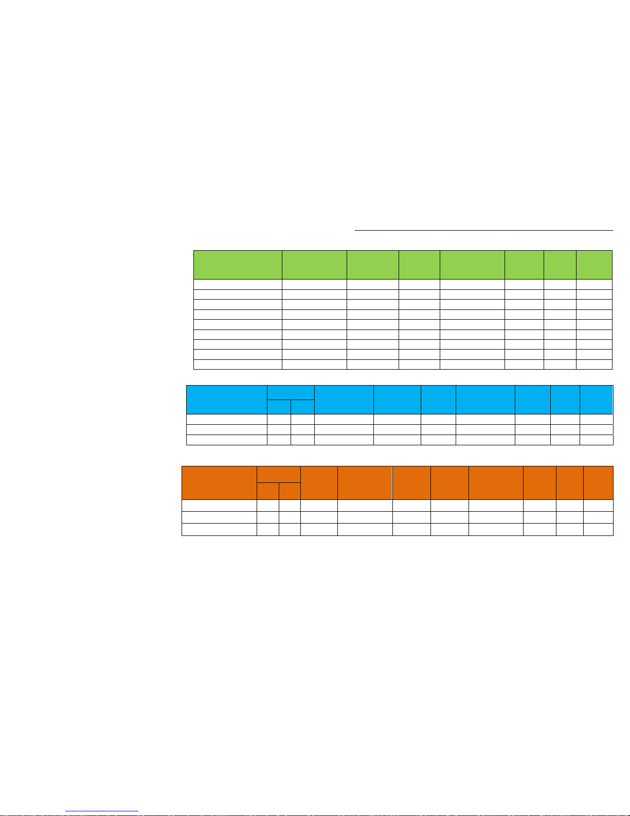
Acoustic Data - MMY Indoor Units
Page 23 of 78
4 Way Compact Cassette High dB(A) Med dB(A) Low dB(A) Ceiling Suspended High dB(A) Med dB(A) Low dB(A)
MMU-AP0074MH-E 36 32 28 MMC-AP0154H-E 35 32 30
MMU-AP0094MH-E 37 33 28 MMC-AP0184H-E 36 33 30
MMU-AP0124MH-E 37 33 29 MMC-AP0244H-E 38 36 33
MMU-AP0154MH-E 40 35 30 MMC-AP0274H-E 38 36 33
MMU-AP0184MH-E 44 39 34 MMC-AP0364H-E 41 38 35
4 Way Cassette High dB(A) Med dB(A) Low dB(A) MMC-AP0484H-E 43 40 37
MMU-AP0094HP-E 30 29 27 High Wall High dB(A) Med dB(A) Low dB(A)
MMU-AP0124HP-E 30 29 27 MMK-AP0073H 35 31 28
MMU-AP0154HP-E 31 29 27 MMK-AP0093H 37 32 28
MMU-AP0184HP-E 32 29 27 MMK-AP0123H 37 32 28
MMU-AP0244HP-E 35 31 28 MMK-AP0153H 41 36 33
MMU-AP0274HP-E 35 31 28 MMK-AP0183H 41 36 33
MMU-AP0304HP-E 38 33 30 MMK-AP0243H 46 39 34
MMU-AP0364HP-E 43 38 32 MMK-AP0074MH-E 35 32 29
MMU-AP0484HP-E 46 38 33 MMK-AP0094MH-E 36 33 29
MMU-AP0564HP-E 46 40 33 MMK-AP0124MH-E 37 33 29
2 Way Cassette High dB(A) Med dB(A) Low dB(A) Concealed Chassis High dB(A) Med dB(A) Low dB(A)
MMU-AP0072WH 34 32 30 MML-AP0074BH-E 36 34 32
MMU-AP0092WH 34 32 30 MML-AP0094BH-E 36 34 32
MMU-AP0122WH 34 32 30 MML-AP0124BH-E 36 34 32
MMU-AP0152WH 35 33 30 MML-AP0154BH-E 36 34 32
MMU-AP0182WH 35 33 30 MML-AP0184BH-E 36 34 32
MMU-AP0242WH 38 35 33 MML-AP0244BH-E 42 37 33
MMU-AP0272WH 38 35 33 Floor Mounted Console High dB(A) Med dB(A) Low dB(A)
MMU-AP0302WH 40 37 34 MML-AP0074H-E 39 37 35
MMU-AP0362WH 42 39 36 MML-AP0094H-E 39 37 35
MMU-AP0482WH 43 40 37 MML-AP0124H-E 45 41 38
MMU-AP0562WH 46 42 39 MML-AP0154H-E 45 41 38
1 Way Cassette High dB(A) Med dB(A) Low dB(A) MML-AP0184H-E 49 44 39
MMU-AP0074YH-E 42 39 34 MML-AP0244H-E 49 44 39
MMU-AP0094YH-E 42 39 34 Bi-Flow Console High dB(A) Med dB(A) Low dB(A)
MMU-AP0124YH-E 42 39 34 MML-AP0074NH-E 38 32 26
MMU-AP0154SH-E 37 35 32 MML-AP0094NH-E 38 32 26
MMU-AP0184SH-E 38 36 34 MML-AP0124NH-E 40 34 29
MMU-AP0244SH-E 45 41 37 MML-AP0154NH-E 43 37 31
Slim Ducted High dB(A) Med dB(A) Low dB(A) MML-AP0184NH-E 47 40 34
MMD-AP0074SPH-E 36 33 30 Floor Mounted Cabinet High dB(A) Med dB(A) Low dB(A)
MMD-AP0094SPH-E 36 33 30 MMF-AP0154H-E 46 43 38
MMD-AP0124SPH-E 38 35 32 MMF-AP0184H-E 46 43 38
MMD-AP0154SPH-E 39 36 33 MMF-AP0244H-E 49 45 40
MMD-AP0184SPH-E 40 38 36 MMF-AP0274H-E 49 45 40
MMD-AP0244SPH-E 49 47 44 MMF-AP0364H-E 51 48 44
MMD-AP0274SPH-E 49 47 44 MMF-AP0484H-E 54 50 46
Standard Ducted High dB(A) Med dB(A) Low dB(A) MMF-AP0564H-E 54 50 46
MMD-AP0076BH-E 29 26 23 Fresh Air Intake High dB(A) Med dB(A) Low dB(A)
MMD-AP0096BH-E 30 26 23 MMD-AP0481HFE 45 43 41
MMD-AP0126BH-E 30 26 23 MMD-AP0721HFE 46 45 44
MMD-AP0156BH-E 33 29 25 MMD-AP0961HFE 46 45 44
MMD-AP0186BH-E 33 29 25 Extra
MMD-AP0246BH-E 36 31 27 Air to Air Heat Exchanger High dB(A) High dB(A) Low dB(A)
MMD-AP0276BH-E 36 31 27 MMD-VN502HEXE 37 36 34
MMD-AP0306BH-E 36 31 27 MMD-VN802HEXE 41 40 38
MMD-AP0366BH-E 40 36 33 MMD-VN1002HEXE 43 42 40
MMD-AP0486BH-E 40 36 33 MMD-VNK502HEXE 36 35 33
MMD-AP0566BH-E 40 36 33 MMD-VNK802HEXE 40 39 38
High Static Ducted High dB(A) Med dB(A) Low dB(A) MMD-VNK1002HEXE 42 41 39
MMD-AP0184H-E 40 37 33
MMD-AP0244H-E 44 40 36
Sound Pressure Levels measured in an anechoic chamber in
accordance with JSI B8616
MMD-AP0274H-E 44 40 36
MMD-AP0364H-E 44 40 36
MMD-AP0484H-E 44 40 36
MMD-AP0724H-E 50 49 48
MMD-AP0964H-E 51 50 49
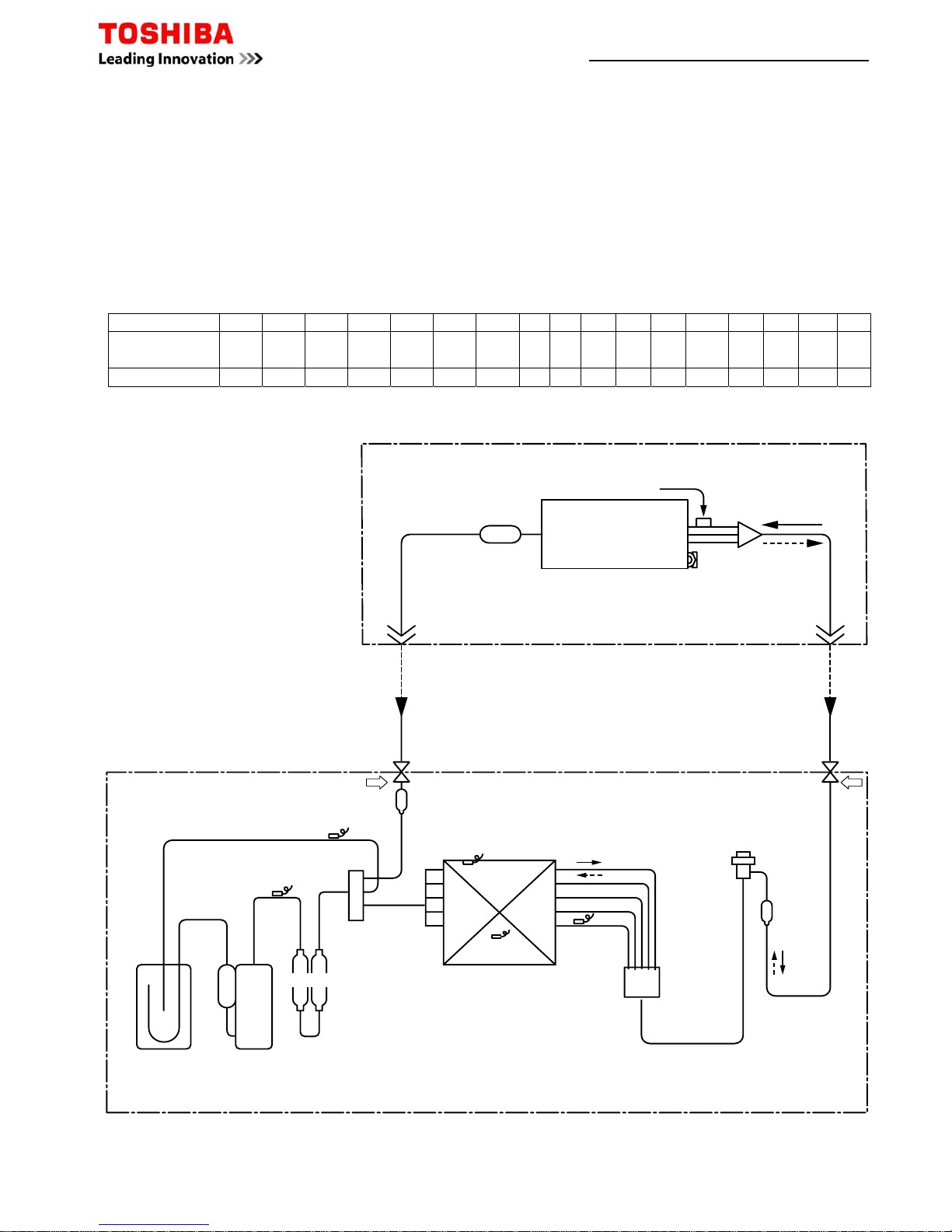
Common Sensor Characteristics
There are eight commonly used sensors in the RAS and RAV systems.
Ta = Return Air Sensor; indoor unit Tc = Coil Sensor; indoor unit
TL = Liquid Pipe Sensor (fan speed); outdoor unit TE = Heat Exchange Sensor (defrost); outdoor unit
Td = Discharge Pipe Sensor; outdoor unit To = Ambient
Ts = Suction Tk = Oil sensor
The Ta,Tc,TL and TE sensors all share the same resistance versus temperature characteristic. They differ however
in electrical connections and sensing head style, therefore it is important to quote the full model type number
when ordering any replacement sensors.
The Td sensor has a different resistance characteristic because its sensing range is that much higher than the
others.
Sensor -10 -5 0 5 10 15 20 25 30 35 40 45 50 55 60 100 ºC
Ta,Tc,TL,TE
To, Ts
60.3 45.3 34.5 26.4 20.5 16 12.5 10 8 6.5 5.3 4.3 3.6 2.9 2.4 - KΩ
Td, Tk - - - - 103 80.5 63 50 - - - - 17.9 - - 3.4 kΩ
Indoor unit
Outdoor unit
Distributor
(Strainer incorporated)
TCJ sensor
Air heat exchanger
Strainer
Strainer
TC sensor
Strainer
Ball valve
Outer dia. ØA
Packed valve
Outer dia. ØB
Max.
50m
Min.
5m
TS sensor
TD sensor
TO sensor
TE
sensor
Distributor
4-way valve
(STF-0213Z
Ø25 × L210
Ø25 × L180
Twin Rotary
compressor
(DA220A2F – 20L)
Accumulator
(2500cc)
Heat exchanger
Outer side
Ø8, 2 rows, 20 steps
FP1.3 flat fin
Inner side
Ø9.52 row, 30 steps
FP1.5 flat fin
R410A 2.5kg
Muffler
Refrigerant pipe
at gas side
Ø15.9
Packet valve
Refrigerant pipe
at liquid side
Ø9.5
Packet valve
PMV
(Pulse Motor Valve)
(UKV-25D22)
Example for location of Sensors
TL sensor
Page 24 of 78
 Loading...