

Toshiba RAS-07 series, RAS-10S series, RAS-10SK series Installation Manual

INSTALLATION MANUAL
MANUAL DE INSTALACIÓN
MANUEL D’INSTALLATION
PУКOBOДCTBO ПO УCTAНOBКE
MONTAJ KILAVUZU
AIR CONDITIONER (SPLIT TYPE)
ACONDICIONADOR DE AIRE (TIPO SPLIT)
CLIMATISEUR (SPLIT SYSTEM)
КOHДИЦИOHEP BOЗДУХA (CПЛИT-CИCTEMA)
KLİMA (SPLİT TİPİ)
RAS-07, 10SK Series
Indoor Unit
Unidad Interior
Unité Intérieure
Bнyтpeнний Блок
İç Ünite
RAS-07, 10S Series
Outdoor Unit
Unidad Exterior
Unité Extérieure
Hapyжный Блок
Dış Ünite
1108651075

CONTENTS
PRECAUTIONS FOR SAFETY ...................................... 1
INSTALLATION DIAGRAM OF INDOOR AND
OUTDOOR UNITS .......................................................... 2
• Optional Installation Parts ................................................ 2
INDOOR UNIT
• Installation Place ............................................................... 3
• Cutting a Hole and Mounting Installation Plate .............. 3
• Electrical Work ................................................................... 4
• Wiring Connection ............................................................. 4
• Piping and Drain Hose Installation .................................. 5
• Indoor Unit Fixing .............................................................. 6
• Drainage ............................................................................. 6
CONTENIDOS
PRECAUCIONES SOBRE SEGURIDAD ....................... 1
DIAGRAMA DE INSTALACIÓN DE LA UNIDAD
INTERIOR Y EXTERIOR ................................................ 2
• Piezas de Instalación Opcional ........................................ 2
UNIDAD INTERIOR
• Lugar de Instalación .......................................................... 3
• Corte de un Orificio y Montaje de la
Placa de Instalación .......................................................... 3
• Trabajo Eléctrico ................................................................ 4
• Conexión de Cables .......................................................... 4
• Instalación la Tubería y el Tubo de Desagüe .................. 5
• Instalación de la Unidad Interior ...................................... 6
• Drenaje ................................................................................ 6
OUTDOOR UNIT
• Installation Place ............................................................... 7
• Refrigerant Piping Connection ......................................... 7
• Evacuating .......................................................................... 7
• Wiring Connection ............................................................. 8
OTHERS
• Gas Leak Test .................................................................... 8
• Setting of Remote Control Selector Switch .................... 8
• Test Operation ................................................................... 9
• Auto Restart Setting .......................................................... 9
UNIDAD EXTERIOR
• Lugar de Instalación .......................................................... 7
• Conexión de la Tubería Refrigerante ............................... 7
• Evacuación .........................................................................7
• Conexión de Cables .......................................................... 8
OTROS
• Comprobación de Fugas ................................................... 8
• Configuración del Interruptor de
Selección del Mando a Distancia ..................................... 8
• Prueba de Operación ......................................................... 9
• Ajuste de Reinicio Automático ......................................... 9
ENGLISH
ENGLISH
ESPAÑOL
SOMMAIRE
MESURES DE SECURITE ............................................. 1
PLAN D’INSTALLATION DES UNITES
INTERIEURE ET EXTERIEURE ..................................... 2
• Pièces d’Installation en Option ........................................ 2
UNITE INTERIEURE
• Endroit d’Installation ......................................................... 3
• Ouverture du Trou et Montage de
la Plaque d’Installation ...................................................... 3
• Travaux Electriques ........................................................... 4
• Connexion des Câbles ...................................................... 4
• Installation de la Conduite et du Tuyau de Purge .......... 5
• Installation de l’Unité Intérieure ....................................... 6
• Drainage ............................................................................. 6
СОДЕРЖАНИЕ
MEPЫ БEЗOПACHOCTИ ............................................. 1
СХЕМА УСТАНОВКИ ВНУТРЕННЕГО
И НАРУЖНОГО БЛОКОВ............................................ 2
• Oпционaльныe Уcтaновочныe Чacти ...........................2
BHУTPEHHИЙ БЛOК
• Mecто Уcтaновки .............................................................. 3
• Пpоpeзaниe Отвepcтия и Монтaж Уcтaновочной
Плacтины ........................................................................... 3
• Элeктpомонтaжныe Рaботы .......................................... 4
• Элeктpичecкиe Cоeдинeния .......................................... 4
• Уcтaновкa Tpyбопpоводов и Дpeнaжной Tpyбки...... 5
• Уcтaновкa Bнyтpeннeго Блокa ..................................... 6
• Дpeнaж ............................................................................... 6
UNITE EXTERIEURE
• Endroit d’Installation ......................................................... 7
• Connexion du Tuyau Réfrigérant ..................................... 7
• Evacuation .......................................................................... 7
• Connexion des Câbles ...................................................... 8
AUTRES
• Test de Fuite Gaz ............................................................... 8
• Réglage du Sélecteur de Télécommande ........................ 8
• Opération du Test .............................................................. 9
• Réglage de la Remise en Marche Automatique .............. 9
HAPУЖHЫЙ БЛOК
• Mecто Уcтaновки .............................................................. 7
• Подcоeдинeниe Tpyбопpоводa для Xлaдaгeнтa ........ 7
• Удaлeниe Воздyxa ...........................................................7
• Элeктpичecкиe Cоeдинeния .......................................... 8
ДPУГИE
• Пpовepкa Отcyтcтвия Утeчки Гaзa ............................... 8
• Уcтaновкa Положeния Пepeключaтeля
Диcтaнционного Упpaвлeния ........................................ 8
• Пpобнaя Экcплyaтaция .................................................. 9
• Уcтaновкa Aвтомaтичecкого Повтоpного Пycкa ....... 9
FRANÇAIS
PYCCKИЙ
PRECAUTIONS FOR SAFETY
For general public use
Power supply cord of parts of appliance for outdoor use shall be at least polychloroprene sheathed flexible cord (design H07RN-F) or
cord designation 245 IEC66. (Shall be installed in accordance with national wiring regulations.)
ENGLISH
CAUTION
This appliance must be connected to the main power supply by means of a circuit breaker or a switch with a contact separation of at
least 3 mm in all poles. If this is not possible, a power supply plug with earth must be used. This plug must be easily accessible after
installation. The plug must be disconnected from the power supply socket in order to disconnect the appliance completely from the mains.
To disconnect the appliance from the main power supply
DANGER
• FOR USE BY QUALIFIED PERSONS ONLY.
• TURN OFF MAIN POWER SUPPLY BEFORE ATTEMPTING ANY ELECTRICAL WORK. MAKE SURE ALL POWER SWITCHES
ARE OFF. FAILURE TO DO SO MAY CAUSE ELECTRIC SHOCK.
• CONNECT THE CONNECTING CABLE CORRECTLY. IF THE CONNECTING CABLE IS CONNECTED WRONGLY, ELECTRIC
PA RTS MAY BE DAMAGED.
• CHECK THE EARTH WIRE THAT IT IS NOT BROKEN OR DISCONNECTED BEFORE INSTALLATION.
• DO NOT INSTALL NEAR CONCENTRATIONS OF COMBUSTIBLE GAS OR GAS VAPORS.
FAILURE TO FOLLOW THIS INSTRUCTION CAN RESULT IN FIRE OR EXPLOSION.
• TO PREVENT OVERHEATING THE INDOOR UNIT AND CAUSING A FIRE HAZARD, PLACE THE UNIT WELL AWAY (MORE THAN
2 M) FROM HEAT SOURCES SUCH AS RADIATORS, HEATERS, FURNACE, STOVES, ETC.
• WHEN MOVING THE AIR CONDITIONER FOR INSTALLING IT IN ANOTHER PLACE AGAIN, BE VERY CAREFUL NOT TO GET
THE SPECIFIED REFRIGERANT (R22) WITH ANY OTHER GASEOUS BODY INTO THE REFRIGERATION CYCLE. IF AIR OR ANY
OTHER GAS IS MIXED IN THE REFRIGERANT, THE GAS PRESSURE IN THE REFRIGERATION CYCLE BECOMES
ABNORMALLY HIGH AND IT RESULTINGLY CAUSES BURST OF THE PIPE AND INJURIES ON PERSONS.
• IN THE EVENT THAT THE REFRIGERANT GAS LEAKS OUT OF THE PIPE DURING THE INSTALLATION WORK, IMMEDIATELY
LET FRESH AIR INTO THE ROOM. IF THE REFRIGERANT GAS IS HEATED BY FIRE OR SOMETHING ELSE, IT CAUSES
GENERATION OF POISONOUS GAS.
WARNING
• Never modify this unit by removing any of the safety guards or bypassing any of the safety interlock switches.
• Do not install in a place which cannot bear the weight of the unit.
Personal injury and property damage can result if the unit falls.
• Before doing the electrical work, attach an approved plug to the power supply cord.
Also, make sure the equipment is properly earthed.
• Appliance shall be installed in accordance with national wiring regulations.
If you detect any damage, do not install the unit. Contact your TOSHIBA dealer immediately.
CAUTION
• Exposure of unit to water or other moisture before installation could result in electric shock.
Do not store it in a wet basement or expose to rain or water.
• After unpacking the unit, examine it carefully for possible damage.
• Do not install in a place that can increase the vibration of the unit. Do not install in a place that can amplify the noise level of the unit
or where noise and discharged air might disturb neighbors.
• To avoid personal injury, be careful when handling parts with sharp edges.
• Please read this installation manual carefully before installing the unit. It contains further important instructions for proper installation.
REQUIREMENT OF REPORT TO THE LOCAL POWER SUPPLIER
Please make absolutely sure that the installation of this appliance is reported to the local power supplier before installation. If you
experience any problems or if the installation is not accepted by the supplier, the service agency will take adequate countermeasures.
Remark per EMC Directive 89/336/EEC
To prevent flicker impressions during the start of the compressor (technical process), following installation conditions does apply.
1.The power connection for the air conditioner has to be done at the main power distribution. This distribution has to be of an impedance.
Normally, the required impedance is reached at a 32A fusing point. Air conditioner fuse has to be 16A max.!
2.No other equipment should be connected to this power line.
3.For detailed installation acceptance, please contact your power supplier whether its restriction does apply for products like washing
machines, air conditioners or electric ovens.
4.For power details of the air conditioner, refer to the rating plate of the product.
1
EN
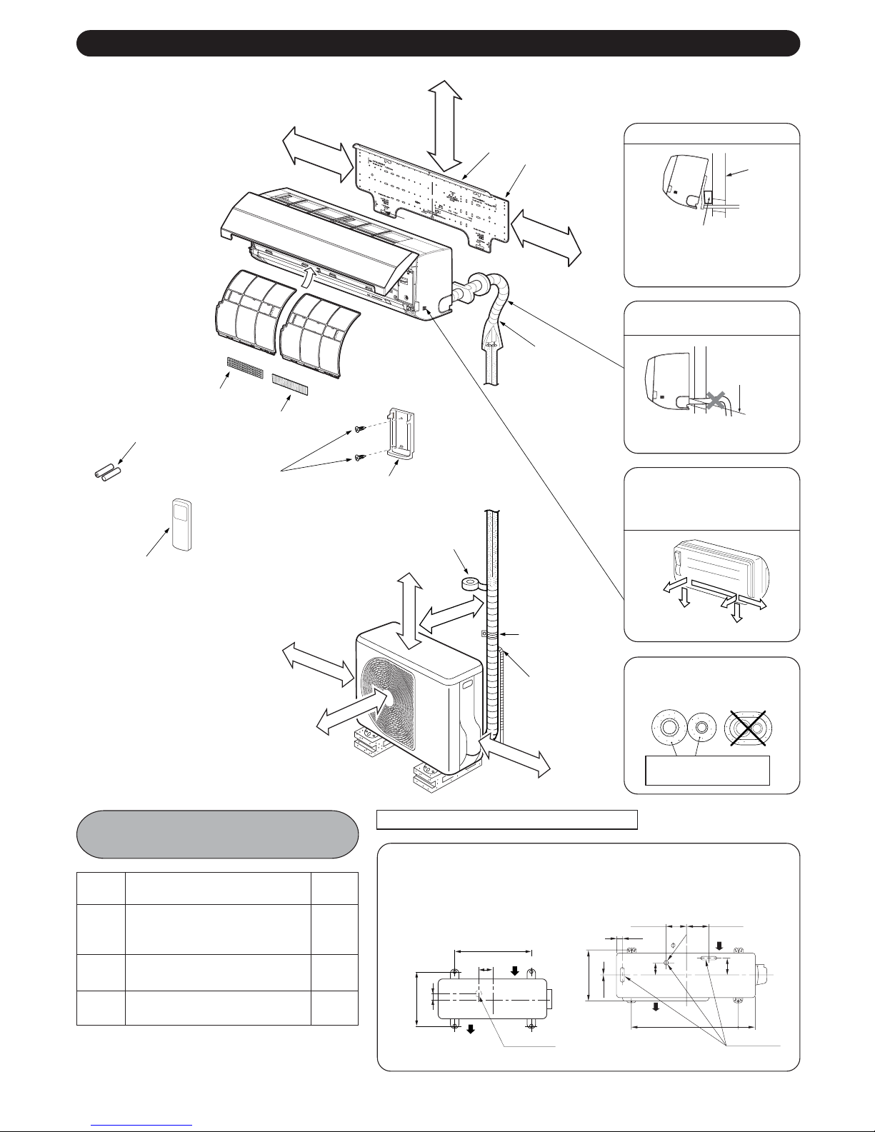
INSTALLATION DIAGRAM OF INDOOR AND OUTDOOR UNITS
5 Filter
3 Batteries
2 Wireless remote control
Remark :
• Detail of accessory and
installation parts can see in
the accessory sheet.
120 mm or more
Air filter
(Attach to the front panel.)
6 Filter
8 Pan head
wood screw
100 mm or more
4 Remote control holder
400 mm or more
47 mm or more
Hook
Vinyl tape
Apply after carrying
out a drainage test.
45 mm or more
600 mm or more
Hook
1 Installation plate
120 mm or more
Shield pipe
Saddle
Extension drain hose
(Not available, provided
by installer)
600 mm or more
For the rear left and left piping
Wall
Insert the cushion between
the indoor unit and wall, and
tilt the indoor unit for better
operation.
Do not allow the drain hose to
get slack.
Cut the piping
hole sloped
slightly.
Make sure to run the drain
hose sloped downward.
The auxiliary piping can be
connected to the left, rear left,
rear right, bottom right or
bottom left.
Rear
right
Bottom right
Rear
left
Left
Bottom left
Insulate the refrigerant pipes
separately with insulation, not
together.
6 mm thick heat resisting
polyethylene foam
Optional Installation
Parts
Part
code
Refrigerant piping
Liquid side : ∅6.35 mm
A
Gas side : ∅9.52 mm
Pipe insulating material
B
(polyethylene foam, 6 mm thick)
Putty, PVC tapes
C
EN 2
Parts name
Q’ty
One
each
1
One
each
Fixing bolt arrangement of outdoor unit
• Secure the outdoor unit with fixing bolts and nuts if the unit is likely to be
exposed to a strong wind.
• Use ∅8 mm or ∅10 mm anchor bolts and nuts.
• If it is necessary to drain the defrost water, attach drain nipple 9 and cap
water proof ! to the bottom plate of the outdoor unit before installing it.
280 mm
53 mm
97 mm
Air outlet
07 Series
500 mm
Air inlet
Drain outlet
320 mm
32.5 mm
7 mm
108 mm
86 mm
Air outlet
600 mm
10 Series
125 mm
Air inlet
30
102 mm
90 mm
Drain outlet
INDOOR UNIT
Installation Place
• A place which provides the spaces around the indoor unit as
shown in the diagram
• A place where there are no obstacles near the air inlet and outlet
• A place which allows easy installation of the piping to the outdoor
unit
• A place which allows the front panel to be opened
CAUTION
• Direct sunlight to the indoor unit’s wireless receiver should be
avoided.
• The microprocessor in the indoor unit should not be too close
to RF noise sources.
(For details, see the owner’s manual.)
Remote control
• A place where there are no obstacles such as a curtain that may
block the signal from the indoor unit
• Do not install the remote control in a place exposed to direct
sunlight or close to a heating source such as a stove.
• Keep the remote control at least 1 m apart from the nearest TV
set or stereo equipment. (This is necessary to prevent image
disturbances or noise interference.)
• The location of the remote control should be determined as
shown below.
(Top view)
Indoor unit
Remote
control
* : Axial distance
5 m
Reception range
45°
5 m
45°
Remote control
Indoor unit
(Side view)
7 m
75°
Reception
range
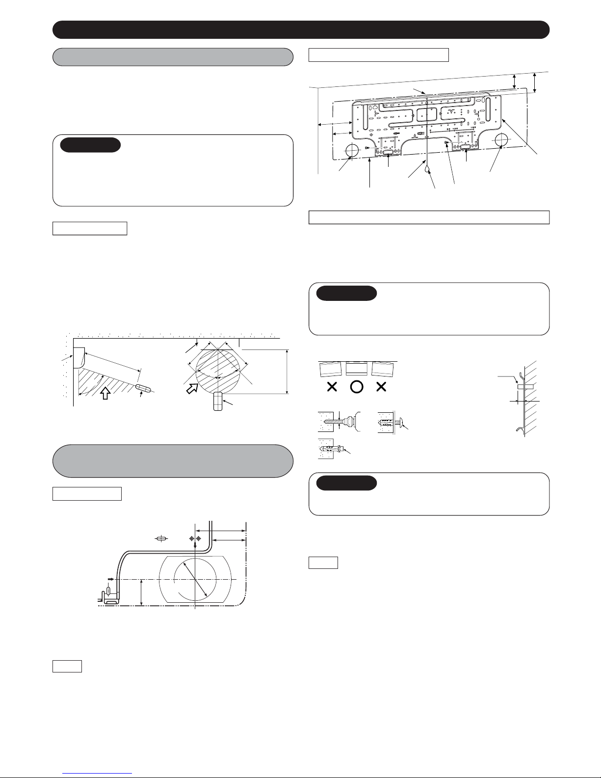
Cutting a Hole and Mounting
Installation Plate
Cutting a hole
When installing the refrigerant pipes from the rear
Mounting the installation plate
Hook
120
65
Hook
Pipe hole
7 Mounting screw
Pipe hole
Indoor unit
Hook
Thread
Weight
When the installation plate is directly mounted on the wall
1.Securely fit the installation plate onto the wall by screwing it in the
upper and lower parts to hook up the indoor unit.
2.To mount the installation plate on a concrete wall with anchor
bolts, use the anchor bolt holes as illustrated in the below figure.
3.Install the installation plate horizontally in the wall.
CAUTION
When installing the installation plate with a mounting screw,
do not use the anchor bolt holes. Otherwise, the unit may fall
down and result in personal injury and property damage.
Installation plate
(Keep horizontal direction.)
ss
s
ss
Anchor bolt
Projection
15 mm or less
* 7 m
5 mm dia. hole
Clip anchor
(local parts)
7 Mounting screw
∅4 x 25
CAUTION
Failure to firmly install the unit may result in personal injury and
property damage if the unit falls.
35
Installation
plate
55.5
1
Pipe hole
42 mm
The center of the pipe hole is above the arrow.
65 mm
1.After determining the pipe hole position on the mounting plate
(A), drill the pipe hole (∅65 mm) at a slight downward slant to
the outdoor side.
NOTE
• When drilling a wall that contains a metal lath, wire lath or metal
plate, be sure to use a pipe hole brim ring sold separately.
90 mm
66 mm
• In case of block, brick, concrete or similar type walls, make 5 mm
dia. holes in the wall.
• Insert clip anchors for appropriate mounting screws 7.
NOTE
• Secure four corners and lower parts of the installation plate with
4 to 6 mounting screws to install it.
3
EN
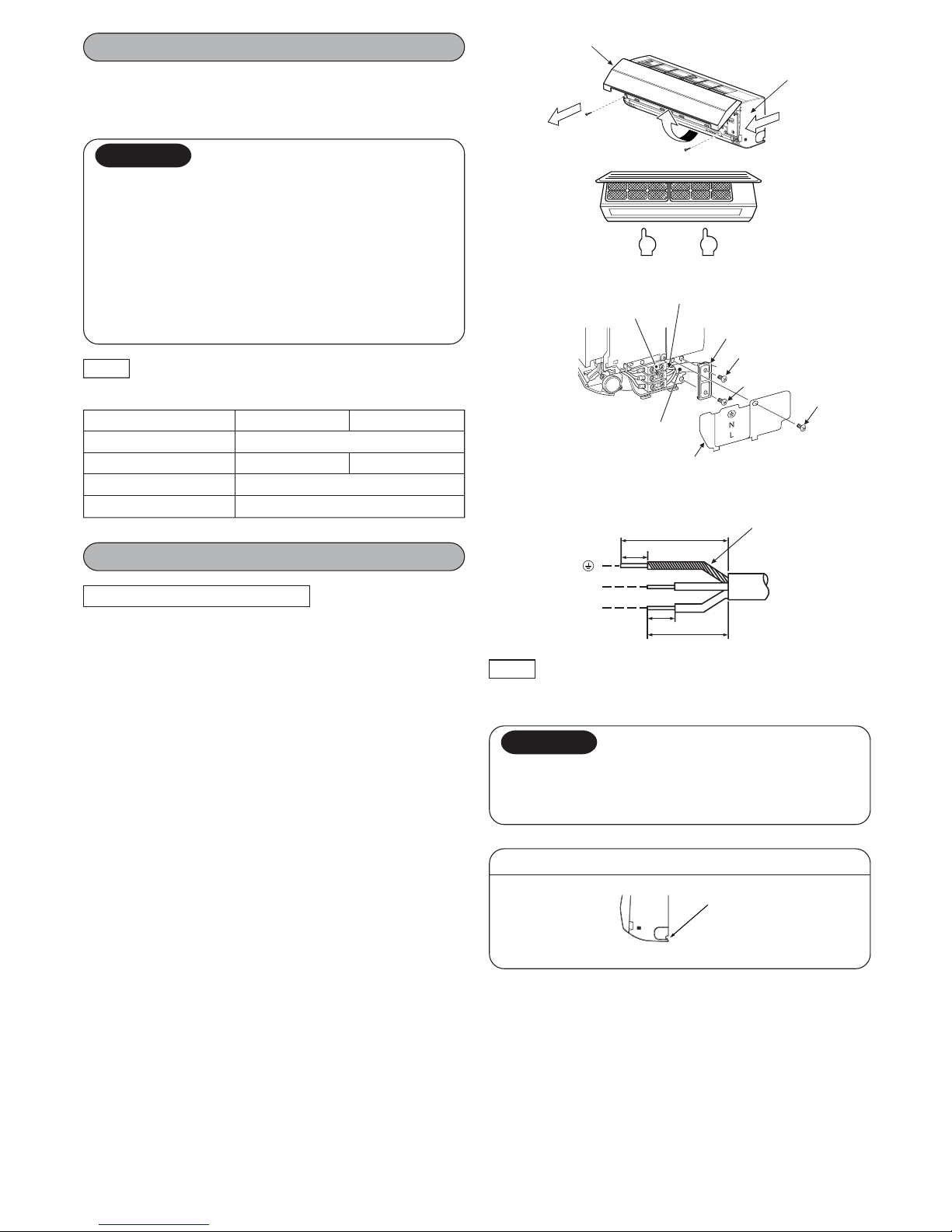
N
L
40 mm
10 mm
30 mm
10 mm
Electrical Work
33
1.The supply voltage must be the same as the rated voltage of the
air conditioner.
2.Prepare the power source for exclusive use with the air
conditioner.
CAUTION
• This appliance can be connected to the mains in either of the
following two ways.
(1) Connection to fixed wiring:
A switch or circuit breaker which disconnects all poles and
has a contact separation of at least 3 mm must be
incorporated in the fixed wiring. An approved circuit breaker
or switches must be used.
(2) Connection with power supply plug:
Attach power supply plug with power cord and plug it into
wall outlet. An approved power supply cord and plug must
be used.
NOTE
• Ensure all wiring is used within its electrical rating.
Model 07 Series 10 Series
Power source 50Hz, 220 – 240 V Single phase
Maximum running current 5A 7.5A
Plug socket & fuse rating 16A
Power cord 1 mm2 or more
Air inlet grille
2
Terminal block
Power supply cord
Power cord connect cover
1
Earth line
3
PushPush
Cord clamp
Screw
Screw
Stripping length of the power supply cord
Earth line
Front panel
Screw
Wiring Connection
How to connect the power cord
For the air conditioner that does not have power cord,
connect a power cord to it as mentioned below.
(1) Open the air inlet grille upward.
(2) Remove the two screws securing the front panel.
(3) Before slightly open the lower part of the front panel, pushing at
specified bottom up until front take off from installation plate.
And then pull the upper part of the front panel toward you to
remove it from the rear plate.
(4) After removing the front panel, remove the power cord connect
cover and the cord clamp.
(5) Connect and secure the power supply cord and secure the cord
clamp and the power cord connect cover.
(6) Put the power supply cord through the notch.
(7) Be sure to smooth the notch with a file, etc.
NOTE
• Use stranded wire only.
• Wire type : H07RN-F or more
CAUTION
For the air conditioner with the power supply cord
• If the power supply cord is damaged, it must be replaced by
the manufacturer, the service agency, or another similarly
qualified person in order to avoid hazard.
Taking out the power cord
Notch
• Put the power supply cord through the notch.
EN 4
 Loading...