

Page 1

Toshiba Personal Computer
Qosmio X300
Maintenance Manual
TOSHIBA CORPORATION
[CONFIDENTIAL]
Page 2

Copyright
© 2008 by Toshiba Corporation. All rights reserved. Under the copyright laws, this manual
cannot be reproduced in any form without the prior written permission of Toshiba. No patent
liability is assumed with respect to the use of the information contained herein.
Toshiba Personal Computer Qosmio X300 Maintenance Manual
First edition June. 2008
Disclaimer
The information presented in this manual has been reviewed and validated for accuracy. The
included set of instructions and descriptions are accurate for the TOSHIBA Qosmio X300 at the
time of this manual's production. However, succeeding computers and manuals are subject to
change without notice. Therefore, Toshiba assumes no liability for damages incurred directly or
indirectly from errors, omissions, or discrepancies between any succeeding product and this
manual.
Trademarks
IBM is a registered trademark and IBM PC is a trademark of International Business Machines
Corporation.
Intel, Intel SpeedStep, Intel® CoreTM, Celeron and Centrino are trademarks or registered
trademarks of Intel Corporation.
Windows, Microsoft and Windows Vista® are registered trademarks of Microsoft Corporation.
Photo CD is a trademark of Eastman Kodak.
Bluetooth is a trademark or registered trademark owned by its proprietor and used by TOSHIBA
under license.
Memory Stick is a registered trademark and i.LINK is a trademark of Sony Corporation.
DVD MovieFactory is a registered trademarks of Ulead Systems, Inc.
Labelflash is a trademark of YAMAHA CORPORATION.
Manufactured under license from Dolby Laboratories.
Dolby and the double-D symbol are trademarks of Dolby Laboratories.
Dolby Home Theater is a trademark of Dolby Laboratories.
PalmCheck and TouchPad are trademarks of Synaptics Incorporated.
ExpressCard is a trademark of PCMCIA.
ConfigFree is a trademark of Toshiba Corporation.
Wi-Fi is a registered trademark of the Wi-Fi Alliance.
Secure Digital and SD are trademarks of SD Card Association.
MultiMediaCard and MMC are trademarks of MultiMediaCard Association.
xD-Picture Card is a trademark of FUJIFILM Corporation.
Other trademarks and registered trademarks not listed above may be used in this manual.
ii
[CONFIDENTIAL]
Qosmio X300 Maintenance Manual
Page 3

Preface
This maintenance manual describes how to perform hardware service maintenance for the
Toshiba Personal Computer Qosmio X300, referred to as the Qosmio X300 Series in this manual.
The procedures described in this manual are intended to help service technicians isolate faulty
Field Replaceable Units (FRUs) and replace them in the field.
SAFETY PRECAUTIONS
Four types of messages are used in this manual to bring important information to your attention.
Each of these messages will be italicized and identified as shown below.
DANGER: “Danger” indicates the existence of a hazard that could result in death or
serious bodily injury if the safety instruction is not observed.
WARNING: “Warning” indicates the existence of a hazard that could result in bodily
injury if the safety instruction is not observed.
CAUTION: “Caution” indicates the existence of a hazard that could result in property
damage if the safety instruction is not observed.
NOTE: “Note” contains general information that relates to your safe maintenance
service.
Improper repair of the computer may result in safety hazards. Toshiba requires service
technicians and authorized dealers or service providers to ensure the following safety precautions
are adhered to strictly.
Be sure to fasten screws securely with the right screwdriver. If a screw is not fully
fastened, it could come loose, creating a danger of a short circuit, which could cause
overheating, smoke or fire.
If you replace the battery pack or RTC battery, be sure to use only the same model battery
or an equivalent battery recommended by Toshiba. Installation of the wrong battery can
cause the battery to explode.
Qosmio X300 Maintenance Manual
[CONFIDENTIAL]
iii
Page 4

The manual is divided into the following parts:
Chapter 1 Hardware Overview describes the Qosmio X300 system unit and each
FRU.
Chapter 2 Troubleshooting Procedures explains how to diagnose and resolve FRU
problems.
Chapter 3 Test and Diagnostics describes how to perform test and diagnostic
operations for maintenance service.
Chapter 4 Replacement Procedures describes the removal and replacement of the
FRUs.
Appendices The appendices describe the following:
Handling the LCD module
Board layout
Pin assignments
Keyboard scan/character codes
Key layout
Screw torque list
Reliability
Conventions
This manual uses the following formats to describe, identify, and highlight terms and operating
procedures.
Acronyms
On the first appearance and whenever necessary for clarification, acronyms are enclosed in
parentheses following their definition. For example:
Read Only Memory (ROM)
Keys
Keys are used in the text to describe many operations. The key top symbol as it appears on the
keyboard is printed in boldface type.
Key operation
iv
[CONFIDENTIAL]
Qosmio X300 Maintenance Manual
Page 5

Some operations require you to simultaneously use two or more keys. We identify such
operations by the key top symbols separated by a plus (+) sign. For example, Ctrl + Pause
(Break) means you must hold down Ctrl and at the same time press Pause (Break). If three
keys are used, hold down the first two and at the same time press the third.
User input
Text that you are instructed to type in is shown in the boldface type below:
DISKCOPY A: B:
The display
Text generated by the computer that appears on its display is presented in the typeface below:
Format complete
System transferred
Qosmio X300 Maintenance Manual
[CONFIDENTIAL]
v
Page 6

Table of Contents
Chapter 1 Hardware Overview
1.1 Features .............................................................................Error! Bookmark not defined.
1.2 2.5-inch HDD..................................................................Error! Bookmark not defined.1
1.3 DVD Super Multi (+-R Double Layer)...........................Error! Bookmark not defined.3
1.4 Power Supply ...................................................................................................................vi4
1.5 Batteries............................................................................................................................vi6
1.5.1 Main Battery………………………………………………………………… vi6
1.5.2 Battery Charing Control …………………………………………………… vi6
1.5.3 RTC battery…………………………………………………………………..vi7
Chapter 2 Troubleshooting Procedures
2.1 Troubleshooting Introduction...........................................................................................2-3
2.2 Troubleshooting Flowchart ............................................2-Error! Bookmark not defined.
2.3 Power Supply Troubleshooting........................................................................................2-9
2.4 Display Troubleshooting...................................……….2-Error! Bookmark not defined.
2.5 Keyboard Troubleshooting.............................................................................................2-17
2.6 External USB Devices Troubleshooting ........................................................................2-19
2.7 TV-Out Failure Troubleshooting ...................................................................................2-21
2.8 TouchPad Troubleshooting ............................................................................................2-23
2.9 Speaker Troubleshooting................................................................................................2-25
2.10 Optical drive troubleshooting………………………………………………………….2-27
2.11 Modem Troubleshooting................................................................................................2-30
2.12 Express card Troubleshooting........................................................................................2-32
2.13 IEEE 1394 Troubleshooting...........................................................................................2-34
2.14 Wireless LAN Troubleshooting.....................................................................................2-36
2.15 Camera troubleshooting………………………………………………………………..2-38
2.16 Bluetooth Troubleshooting……………………………………………………………..240
vi
[CONFIDENTIAL]
Qosmio X300 Maintenance Manual
Page 7

2.17 4 in 1 card Troubleshooting…………………………………………………….…...…2-42
2.18 HDD Troubleshooting……………………………………………………………....….2-44
2.19 CRT failure Troubleshooting ………………………………………………….……....2-46
2.20 HDMI Troubleshooting …………………………………………………….……….…2-
48
2.21 Robson Troubleshooting ……………………………………………………….……...2-50
2.22 MIC Troubleshooting ……………………………………………………………….....2-52
2.23 Finger Troubleshooting ……………………………………………………………..…2-54
Chapter 3 Tests and Diagnostics
3.1 The Diagnostic Test...........................................................Error! Bookmark not defined.
3.2 Executing the Diagnostic Test.........................................Error! Bookmark not defined.3
3.3 Display Configuration .......................................................Error! Bookmark not defined.
3.4 Beep sound Test.................................................................Error! Bookmark not defined.
3.5 Fan ON/OFF Test ............................................................Error! Bookmark not defined.9
3.6 Main Battery Charge Test..................................................Error! Bookmark not defined.
3.7 FDD Test............................................................................Error! Bookmark not defined.
3.8 ODD Test...........................................................................Error! Bookmark not defined.
3.9 Keyboard Test..................................................................Error! Bookmark not defined.5
3.10 Mouse (Pad) Test.............................................................Error! Bookmark not defined.7
3.11 LCD Pixels Mode Test ...................................................................................................vii8
3.12 Magnetic switch Test.................................................................................................... vii19
3.13 LAN Test ........................................................................................................................vii0
3.14 RTC Test........................................................................................................................3-23
3.15 Read 1394 GUID...........................................................................................................3-24
3.16 Speaker EQ Check…………...………….…….……………..……………....…….......3-25
3.17 Button Test …………..……………………….………….……………….….…….….3-26
3.18 Memory Test ……………………....…………….………………..….….……3-26
3.19 1st HDD Test …………………………….………………...…………...3-27
3.20 2nd HDD Test................................................................................................................3-31
3.21 RDMI Test ………………………….………………………..…………….………..3-33
3.22 WDMI Test ……………….………………………..…………….………...3-39
Qosmio X300 Maintenance Manual
[CONFIDENTIAL]
vii
Page 8

3.23 Memory read and Write test …………………………………………………………...3-35
Chapter 4 Replacement Procedures
4.1 General .............................................................................. Error! Bookmark not defined.
4.2 Battery .............................................................................Error! Bookmark not defined.8
4.3 HDD .......................................................................... Error! Bookmark not defined.10
4.4 Memory ..........................................................................Error! Bookmark not defined.3
4.5 Keyboard cover and Keyboard…………….................... Error! Bookmark not defined.6
4.6 Wireless LAN Card and UWB Card............................... Error! Bookmark not defined.9
4.7 ODD ............................................................................ Error! Bookmark not defined.2
4.8 Express Dummy Card .....................................................Error! Bookmark not defined.6
4.9 Optical Memory Card......................................................Error! Bookmark not defined.8
4.10 Top Cover........................................................................ Error! Bookmark not defined.9
4.11 Display Assembly............................................................Error! Bookmark not defined.2
4.12 DC in jack........................................................................Error! Bookmark not defined.5
4.13 Speakers.............................................................................Error! Bookmark not defined.
4.14 Touch pad and fingerprint board.......................................Error! Bookmark not defined.
4.15 Power Switch................................................................. Error! Bookmark not defined.40
4.16 Audio card....................................................................... Error! Bookmark not defined.1
4.17 MDC Moudule & System Board..................................... Error! Bookmark not defined.3
4.18 VGA Board and VGA Cooling Module.......................... Error! Bookmark not defined.5
4.19 CPU Cooling Module and Fan.......................................... Error! Bookmark not defined.
4.20 CPU ............................................................................Error! Bookmark not defined.2
4.21 Sub-speakers and Sub-woofer.........................................Error! Bookmark not defined.5
4.22 Bluetooth, Wi-Fi Switch, and Touch Pad LED Board....Error! Bookmark not defined.6
4.23 Bridge Media and FM Radio Modules..............................Error! Bookmark not defined.
4.24 Display Mask................................................................... Error! Bookmark not defined.8
4.25 FL Inverter Board............................................................ Error! Bookmark not defined.0
4.27 LCD Module....................................................................Error! Bookmark not defined.2
viii
[CONFIDENTIAL]
Qosmio X300 Maintenance Manual
Page 9

Appendices
Appendix A Handling the LCD Module ................................................................................. A-1
Appendix B Board Layout ...................................................................................................... B-1
Appendix C Pin Assignments.................................................................................................. C-1
Appendix D Keyboard Scan/Character Codes ........................................................................ D-1
Appendix E Key Layout...........................................................................................................E-1
Appendix F Series Screw Torque List.....................................................................................F-1
Appendix G Reliability............................................................................................................ G-1
Qosmio X300 Maintenance Manual
[CONFIDENTIAL]
ix
Page 10

Chapter 1 Hardware Overview
Page 11

1 Hardware Overview
Qosmio X300 Maintenance Manual 1-ii
Page 12

1 Hardware Overview
Chapter 1 Contents
1.1 Features .................................................................................................................. 1-1
1.2 2.5-inch HDD....................................................................................................... 1-11
1.3 DVD Super Multi (+-R Double Layer)................................................................ 1-13
1.4 Power Supply ....................................................................................................... 1-14
1.5 Batteries................................................................................................................ 1-16
1.5.1 Main Battery......................................................................................... 1-16
1.5.2 Battery Charging Control .....................................................................1-16
1.5.3 RTC Battery..........................................................................................1-17
Qosmio X300 Maintenance Manual 1-iii
Page 13

1 Hardware Overview
Figures
Figure 1-1A ID Parts Description Placement Part A..........................................................1-6
Figure 1-2B ID Parts Description Placement Part B..........................................................1-7
Figure 1-3 SATA HDD .................................................................................................1-11
Figure 1-4 DVD Super Multi Drive ..............................................................................1-13
Tables
Table 1-1 HDD Specifications .....................................................................................1-11
Table 1-2 DVD Super Multi Drive Specifications....................................................... 1-13
Table 1-3 Quick/Normal Charging Time ..................................................................... 1-16
Qosmio X300 Maintenance Manual 1-iv
Page 14

Error! Style not defined. Error! Style not defined. 1 Hardware Overview
1.1 Features
The Toshiba Qosmio X300 a full size notebook PC based on the Dual Core and Quad Core
Processor, providing high-speed processing capabilities and advanced features. The computer
employs a Lithium Ion battery that allows it to be battery-operated for a longer period of time.
The display uses 17.1-inch WXGA/WSXGA LCD panel, at a resolution of 1440 by 900 pixels.
The PGA socket supports BTO for the CPU so that the system can be designed to suit your needs.
The computer has the following features:
Processor (BTO)
The computer is equipped with one of the following Intel® processors.
■ Intel® Dual CoreTM 2 Duo Processor
■ Intel® Quad CoreTM 2 Duo Processor
Memory (BTO)
The computer has two SO-DIMMs slot comes standard with 1GB/2GB/4GB, accepting
BTO/CTO for your memory requirements. It can incorporate up to 8 GB of main memory.
It supports DDR3 at 1067/800MHz.
Battery Pack
The computer is powered by one rechargeable and removable 8 Cell Lithium Ion battery
pack.
RTC Battery
The internal RTC battery backs up the Real Time Clock and calendar.
Hard Disk Drive (HDD) (BTO)
The computer accommodates 9.5 mm and 12.5 mm two kinds of height HDD types with
following storage capacities:
y 160/200/250/320 GB (9.5 mm thick) SATA (5,400rpm)
y 160/200/320 GB (9.5 mm thick) SATA (7,200rpm)
Qosmio X300 Maintenance Manual 1-1
Page 15

1 Hardware Overview Error! Style not defined. Error! Style not defined.
y 300/400/500 GB (12.5 mm thick) SATA (4,200rpm)
y 500 GB (12.5 mm thick) SATA (5,400rpm)
ODD (BTO)
y 12.7mm height DVD Super Multi drive supporting ±R Double Layer
y 12.7mm height DVD Super Multi drive supporting ±R Double Layer w/ Labelflash
Display (BTO)
The LCD displays available come with one of following types:
y 17.1” WXGA CSV 1-Lamp color display, resolution 1440×900
y 17.1” WSXGA CSV 1-Lamp color display, resolution 1680×1050
Graphics (BTO)
Intel PM45 with NB9E-GS/NB9E-GTX (depending on model)
Keyboard
The internal keyboard provides the embedded numeric overlay keys, dedicated cursor
control overlay keys, and so on. The keyboard is compatible with the IBM® enhanced
keyboard.
Pointing Device
The integrated Touch Pad and control buttons in the palm rest allow control of the onscreen pointer and support functions such as the scrolling of windows.
External Monitor Port
The analog VGA port provides support for VESA DDC2B compatible functions.
Qosmio X300 Maintenance Manual 1-2
Page 16

Error! Style not defined. Error! Style not defined. 1 Hardware Overview
Universal Serial Bus (USB) Ports
The computer has four USB 2.0 ports. It is supported to daisy-chain a maximum of 127
USB devices. The serial data transfer rate is 480 Mbps or 12 Mbps and 1.5 Mbps. These
ports support PnP installation and hot plugging. They also support Sleep and Charge
function.
IEEE1394
This port allows high-speed data transfer to take place between the computer and external
devices such as digital video cameras.
Express Card Slot
A PC Card slot is provided to hold PC Card Standard Type II (5.0 mm) card, capable of
using a variety of PC Cards including 16-bit Multiple Function PC Cards and 32-bit Card
Bus Cards.
PC card HDD boot does not be supported.
Bridge Media Slot
This slot allows you to insert SD, MiniSD/ MicroSD (through adapter), Memory
Stick/Memory Stick Duo (through adaptor), Memory Stick Pro/Memory Stick Duo (through
adaptor), XD and MMC memory card. It supports High speed SD, SDHC and SDIO. An
I/O port heel cover is needed. This model does not support CF cards.
Sound system
The integrated sound system provides support for the computer's internal speakers and
microphone, as allowing an external microphone and headphones to be connected via the
appropriate jacks.
Internal Camera
It supports 1.3M pixels with/without auto macro. It comes with blue LED. Camera and
microphone need to work separately.
HDMI Out Port (BTO)
HDMI out port can connect with Type A connector HDMI cable.
Qosmio X300 Maintenance Manual 1-3
Page 17

1 Hardware Overview Error! Style not defined. Error! Style not defined.
DisplayPort Out Port (BTO)
DisplayPort out port can connect with DisplayPort cable.
Headphones/S/PDIF/Line out Jack
This jack connects digital speakers or a stereo headphone (16 ohm minimum). When
connected to a digital speaker or headphones, the internal speaker is automatically disabled.
This jack can be used also as S/PDIF jack and enables connection of optical digital
correspondence apparatus.
Microphone/ Line-in Jack
A 3.5mm mini microphone jack enables connection of a three-conductor microphone for
monaural input and also enables the connection of a stereo device for audio input.
LAN (BTO)
The computer has built-in support for Ethernet LAN (10 megabits per second, 10BASE-T),
Fast Ethernet LAN (100 megabits per second, 100BASE-TX) and Gigabit Ethernet LAN
(1000 megabits per second, 1000BASE-T). It is pre-installed as a standard device in some
markets.
Wireless LAN (BTO)
Some computers in this series are equipped with a Wireless LAN card that is compatible
with other LAN systems based on Direct Sequence Spread Spectrum/Orthogonal Frequency
Division Multiplexing radio technology that complies with the IEEE 802.11 Standard
(Revision A, B, G or N Draft Ver. 1.0).
Internal Modem (BTO)
Some models are equipped with the integrated modem. The integrated modem provides
capability for data and fax communications that support the V.90 (V.92) standards and
includes a modem jack for connection to the telephone line. Please note that both the V.90
and V.92 standards are only supported in the USA, Canada, United Kingdom, France,
Germany and Australia - only the V.90 standard is supported in other regions. You should
also be aware that the speed of data and fax transfer will depend on the analog telephone
line conditions. The integrated model is only installed as a standard device in some markets.
Qosmio X300 Maintenance Manual 1-4
Page 18

Error! Style not defined. Error! Style not defined. 1 Hardware Overview
Bluetooth (BTO)
Some computers in this series offer Bluetooth wireless communication functionality which
eliminates the need for cables between electronic devices such as computers and printers.
When implemented, Bluetooth provides a fast, reliable and secure means to achieve
wireless communication in a small space.
Finger Print (BTO)
This product has a fingerprint utility installed for the purpose of enrolling and recognizing
fingerprints. By enrolling the ID and password to the fingerprint authentication device, it is
no longer necessary to input the password from the keyboard. Just by swiping the finger
against the fingerprint sensor.
Internal Camera (BTO)
The computer has an internal camera. The camera has 1.3 Mpix resolution support.
Qosmio X300 Maintenance Manual 1-5
Page 19
1 Hardware Overview Error! Style not defined. Error! Style not defined.
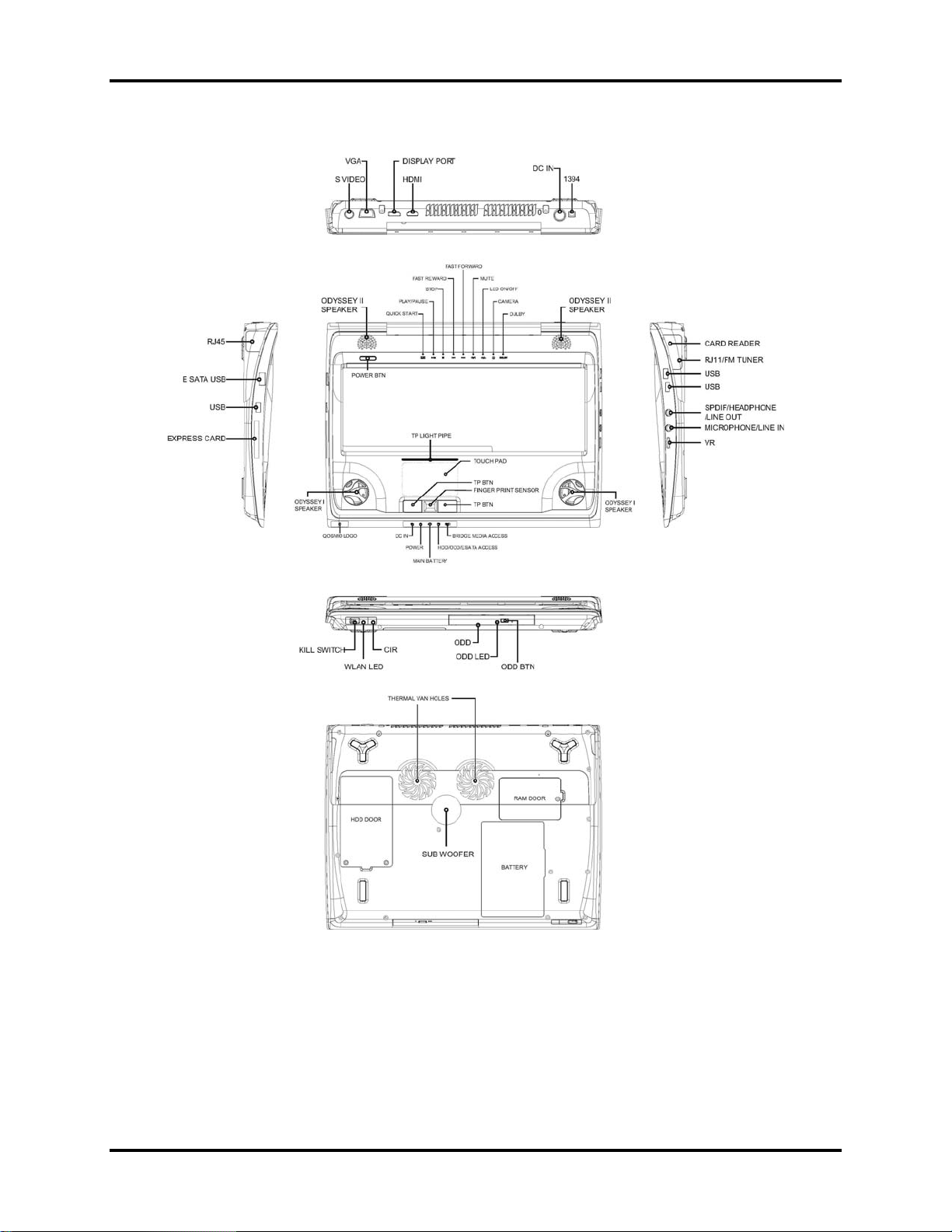
Figures 1-1A/1-1B/1-1C show the computer and its system unit configuration, respectively.
Figure 1-1A ID Parts Description Placement Part A
Qosmio X300 Maintenance Manual 1-6
Page 20
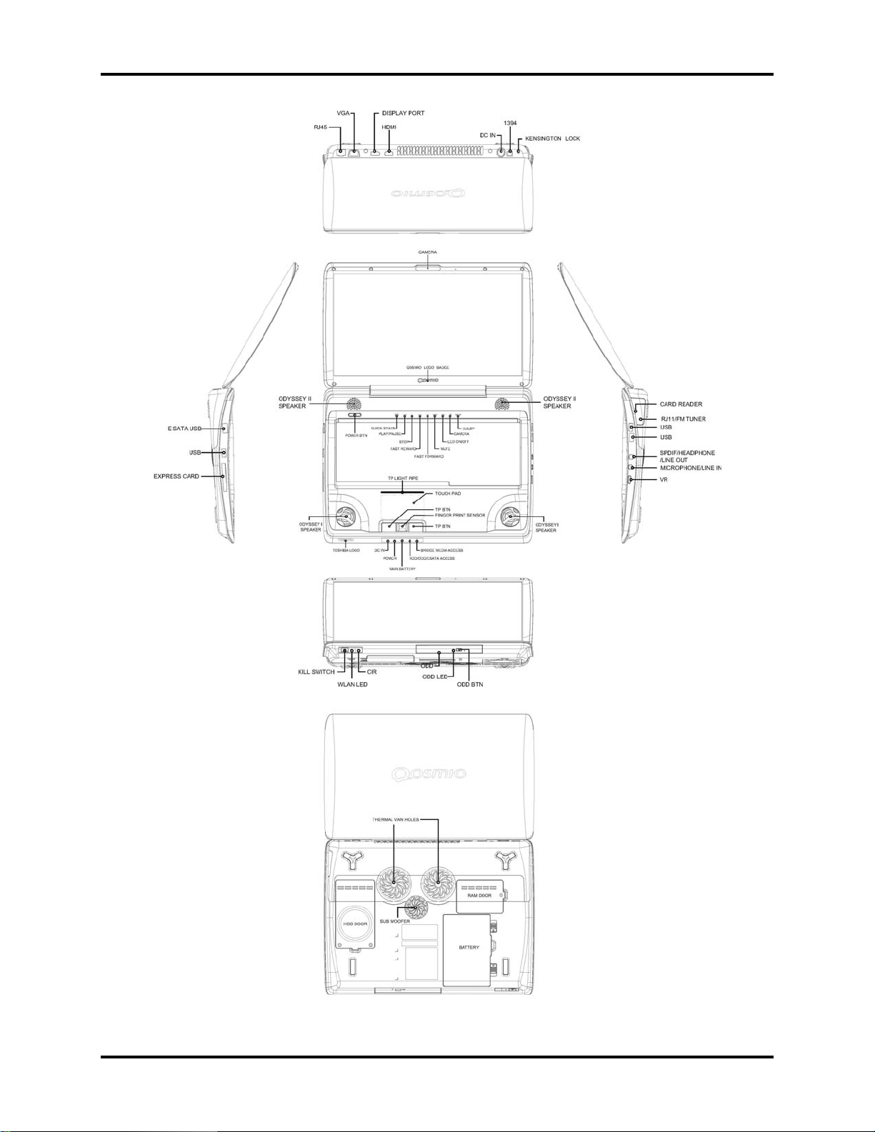
Error! Style not defined. Error! Style not defined. 1 Hardware Overview
Figure 1-2B ID Parts Description Placement Part B
Qosmio X300 Maintenance Manual 1-7
Page 21
1 Hardware Overview Error! Style not defined. Error! Style not defined.
Qosmio X300 Maintenance Manual 1-8
Page 22

Error! Style not defined. Error! Style not defined. 1 Hardware Overview
The system unit of the computer consists of the following components:
Processor (BTO)
The computer is equipped with one of the following Intel® processors.
■ Intel® Dual CoreTM 2 Duo Processor
■ Intel® Quad CoreTM 2 Duo Processor
Memory (BTO)
The computer has two SO-DIMMs slot comes standard with 1GB/2GB/4GB, accepting
BTO/CTO for your memory requirements. It can incorporate up to 8 GB of main memory.
It supports DDR2 at 1067/800MHz.
BIOS ROM
y 2048KB flash BIOS ROM
y ACPI-compliant BIOS
y SMBIOS V2.4
System Controllers
y Advanced Power Management 1.2 support
y ACPI2.0 b and PC2001 compliant
y Support SMBus specification V2.0
y Hot keys for system control
y Audio volume output control
y External LED control
y Battery scope report and control
y Sticky key support
y Power switch control
y Two host interface channels support
y Supports three independent devices
y Internal Keyboard country selection
y Wireless LAN on/off button
Qosmio X300 Maintenance Manual 1-9
Page 23

1 Hardware Overview Error! Style not defined. Error! Style not defined.
Graphics Controller
y Daughter board with extension graphic card
y For Single:
− NB9E-GTX with 1GB DDR3
− NB9E-GS with 512MB DDR3
y HDMI 1.3a -CEC support
y DVI-D supported by conversion cable from HDMI
y Hybrid-Power/SLi support
Express Card Controller
y Dummy card with ID shape
y Support USB/PCI Express signals
y One Express card slot/54
Audio Controller
y Realtek Azalia ALC272
y Microsoft inbox audio driver support
y Software EQ support
y Synchronize to change sound output to HDMI when display is changed to HDMI out
with audio output capability
y MAXX audio support by SW solution (BTO by image)
Wireless LAN Controller
y Intel 11a/g (Golan), Intel 11bg (Golan), 11a/g/n (Kedron), (TBD)
y Intel 802.11a/g (Echo Peak 1x2 & Shirley Peak 1x2)
y Intel 802.11a/g/n (Echo Peak 3x3 Shirley Peak 3x3)
y Atheros 802.11a/g (XB62L 1x2), b/g (XB63L 1x2), a/b/g/n (XB72 2x3), a/b/g/n (XB92
2x2)
y Realtek 802.11bg (8187B 1X2) (TBD)
y Intel WiMAX 802.16e (Echo Peak 3x3)
y Normal screw for all model
Qosmio X300 Maintenance Manual 1-10
Page 24
Error! Style not defined. Error! Style not defined. 1 Hardware Overview
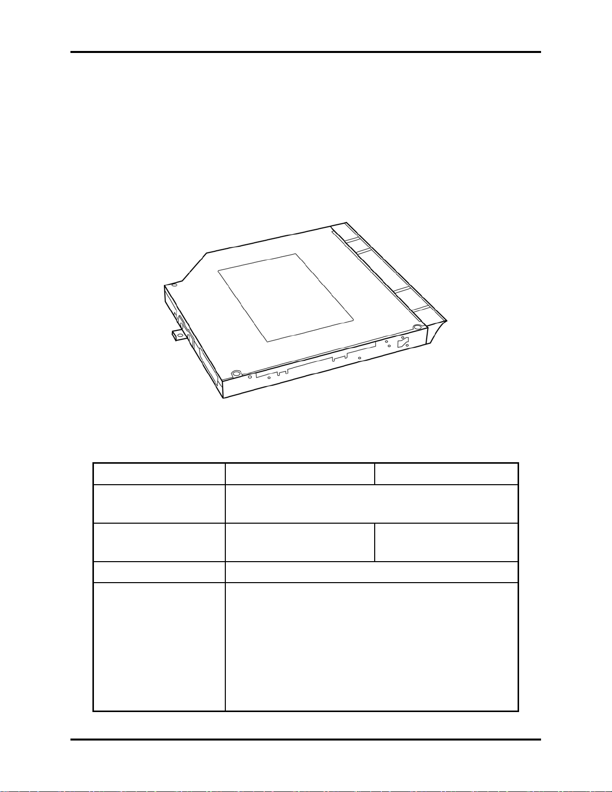
1.2 2.5-inch HDD
The computer contains an extremely low-profile and lightweight, high-performance HDD. The
HDD incorporates 9.5 mm / 12.5 mm height magnetic disk and mini-Winchester type magnetic
heads. The HDD interface conforms to Serial ATA. Storage capacities supported are 160, 200,
250, 320, 400, and 500 GB.
The HDD is shown in Figure 1-3 and some of its specifications are listed in Table 1-1.
Figure 1-3 SATA HDD
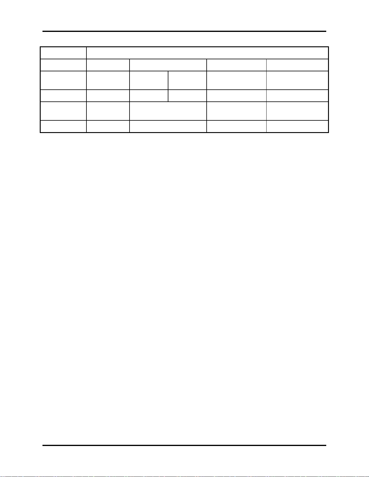
Table 1-1 HDD Specifications
Item
Capacity (GB) 160 GB 200 GB 250 GB
Rotational
Speed (RPM)
Height 12.5 mm 9.5 mm 9.5mm 9.5 mm 9.5 mm 9.5mm 9.5 mm
User Data
Sectors
Bytes / Sector 512 512 512
4200
RPM
5400
RPM
312,581,808 390,721,968 488,397,168
7200
RPM
Specifications
4200
RPM
5400
RPM
7200
RPM
5400 RPM
Qosmio X300 Maintenance Manual 1-11
Page 25
1 Hardware Overview Error! Style not defined. Error! Style not defined.
Item
Capacity (GB)
Rotational
Speed (RPM)
Height
User Data
Sectors
Bytes / Sector
Specifications
300 GB 320 GB 400 GB 500 GB
4200 RPM 5400 RPM 7200 RPM 4200 RPM 4200 RPM
12.5 mm 9.5 mm 9.5mm 12.5 mm 12.5
576,072,368 625,142,808 781,422,768 976,773,168
512 512 512 512
Qosmio X300 Maintenance Manual 1-12
Page 26
Error! Style not defined. Error! Style not defined. 1 Hardware Overview
1.3 DVD Super Multi (+-R Double Layer)
The DVD Super Multi drive accepts 12-cm (4.72-inch) and 8-cm (3.15-inch) discs. At maximum,
the drive can play back a DVD at 8x speed, read CD-ROM at 24x speed, and write CD-R at 24x
speed, CD-RW at 4x speed, US CD-RW at 24x speed, High Speed CD-RW at 10x speed, DVDR at 8x speed, DVD-RW at 6x speed, DVD+R at 8x speed, DVD+R (Double Layer) at 4x speed,
DVD-R (Double Layer) at 4x speed, DVD+RW at 8x speed and DVD-RAM at 5x speed.
The DVD Super Multi drive is shown in Figure 1-4 and its specifications are listed in Table 1-2.
Figure 1-4 DVD Super Multi Drive
Table 1-2 DVD Super Multi Drive Specifications
Item DVD-ROM Mode CD-ROM Mode
Data Transfer Rate
(Mbytes/s)
Access Time (ms)
Average Random Access 130 130
Data Buffer Size (Mbytes) 2MB
Formats Supported
SATA 1.5G
16.6 (PIO mode 4, Multiword DMA mode 2)
DVD:
DVD-VIDEO, DVD-ROM, DVD-R, DVD-RW, DVD-RAM,
DVD+R, DVD+-R (Double Layer), DVD+RW.
CD:
CD-DA, CD-ROM, CD-R, CD-RW, CD-ROMXA, Photo CD
(Multi-Session), Video CD, CD-Extra (CD+), CD-Text.
Qosmio X300 Maintenance Manual 1-13
Page 27

1 Hardware Overview Error! Style not defined. Error! Style not defined.
1.4 Power Supply
The power supply unit provides constant voltage 19V for the system board and performs the
following functions:
1. Power input monitor
y Checks whether the AC adapter (DC power supply) is connected to the computer.
y Checks whether the battery pack is connected to the computer.
y Monitors the DC power supply input voltage (AC Adapter output voltage).
2. Power supply's internal control
y Turns on and off the battery pack charging power supply.
y Issues a charging current instruction to the PWM control IC of the battery pack charging
power supply.
y Controls the supply of DC power supply input (AC Adapter output) to the power supply
unit.
y Controls the supply of power to the system block (load/logic circuit side).
y Controls forced shutdown if the power supply malfunctions.
3. Logic circuit control
y Instructs the gate array to enable/disable tuning the power on.
y Controls power-on/off operation.
4. Status display
y Shows DC-IN (Red Color)
y Shows Power (Red/Amber)
y Shows Main Battery charging (Red/Amber Color).
5. External interface
y Performs communication through the I2C bus (via the internal EC/KBC).
y Transfers the power supply operation mode.
Qosmio X300 Maintenance Manual 1-14
Page 28

Error! Style not defined. Error! Style not defined. 1 Hardware Overview
6. Output monitor
y Monitors the voltage output to the system block (load/logic circuit side).
y Monitors the voltage, over voltage, input/output current of the battery pack.
y Monitors the internal temperature of the battery pack.
y Monitors the supply voltage from the AC adapter.
Qosmio X300 Maintenance Manual 1-15
Page 29
1 Hardware Overview Error! Style not defined. Error! Style not defined.
1.5 Batteries
The computer has the following two types of batteries:
Main Battery Pack
Real Time Clock (RTC) Battery
1.5.1 Main Battery
The main battery pack serves as the computer's main power source when the AC adapter is not
attached. The main battery maintains the state of the computer so that it can resume it.
1.5.2 Battery Charging Control
Battery charging is controlled by EC KB926. When the AC adapter and battery pack are attached
to the computer, the EC KB926 controls the charge on/off state and detects a full charge.
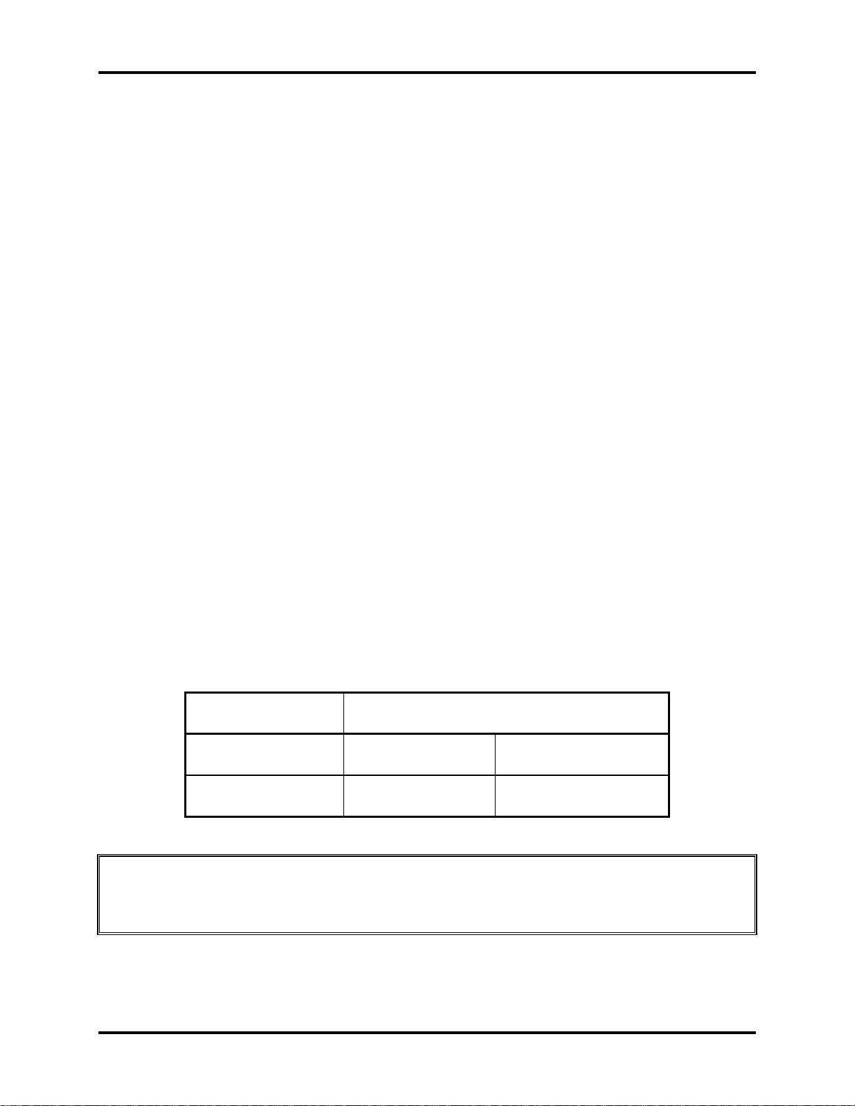
Battery Charge
When the AC adapter is attached, the battery is charged by off-state charge when the system
is powered off or by on-state charge when it is powered on.
Table 1-3 Quick/Normal Charging Time
State Charge Time
Off-State Charge 8 Cell About 4 hours max
On-State Charge 8 Cell About 12 hours max
NOTE: The time required for normal charge depends on the power consumption by the
system. Using the fluorescent lamp and frequently accessing the disk consume much power
and lengthen the charge time.
Qosmio X300 Maintenance Manual 1-16
Page 30

Error! Style not defined. Error! Style not defined. 1 Hardware Overview
Any of the following cases stops battery charge:
1. The battery becomes fully charged.
2. The AC adapter or battery pack is removed.
3. The battery or AC adapter voltage is abnormal.
Detection of full charge
A full charge is detected only when the battery is being charged by quick or normal charge.
A full charge is detected when either of the following conditions is met:
1. The current in the battery charging circuit drops below the predetermined value.
2. The charging time exceeds the fixed limit.
1.5.3 RTC Battery
The RTC battery provides power to keep the current date, time and other system information in
memory while the computer is turned off.
Qosmio X300 Maintenance Manual 1-17
Page 31

Chapter 2
Troubleshooting Procedures
2
Page 32

Page 33

2 Troubleshooting Procedures
Chapter 2 Contents
2.1 Troubleshooting Introduction ........................................................................................4
2.2 Troubleshooting Flowchart............................................................................................5
2.3 Power Supply Troubleshooting....................................................................................10
2.4 Display Troubleshooting..............................................................................................15
2.5 Keyboard Troubleshooting ..........................................................................................18
2.6 External USB Devices Troubleshooting..........................................................................20
2.7 TouchPad Troubleshooting................................................................................................22
2.8 Speaker Troubleshooting...................................................................................................24
2.9 Optical Drive Troubleshooting....................................................................................26
2.10 Modem Troubleshooting..............................................................................................30
2.11
2.12 IEEE 1394 Troubleshooting ........................................................................................34
2.13 W
2.14 Camera Troubleshooting..............................................................................................39
2.15 Bluetooth Troubleshooting ..........................................................................................41
2.16 7in 1 card Troubleshooting ..........................................................................................44
2.17 HDD Troubleshooting .................................................................................................46
2.18 CRT Troubleshooting ......................................................................................................48
2.19 HDMI Troubleshooting ...................................................................................................50
2.23 FM tuner Failure Troubleshooting...................................................................................58
2.24 E-SATA Troubleshooting............................................................................................61
2.25UWB Troubleshooting
2.26 Display port Troubleshooting
2.10
2.11 Express card Troubleshooting......................................................................................30
Express card Troubleshooting......................................................................................32
ireless LAN Troubleshooting...................................................................................36
......................................................................................................63
..........................................................................................66
Modem Troubleshooting …………….……………………………………………....28
2.12 IEEE 1394 Troubleshooting ........................................................................................32
2.13 Wireless LAN Troubleshooting...................................................................................34
2.14 Camera troubleshooting...............................................................................................37
2.15 Bluetooth Troubleshooting………………......……...…………………….……….. ..39
2.16 7 in 1 card Troubleshooting……………………………………………………..…….42
2-17 HDD troubleshooting process……………………………….………………..............44
2-18 CRT failure troubleshooting process …………………………………………………46
QOSMIO X300 Series Maintenance Manual
1
Page 34

2 Troubleshooting Procedures
2-19 HDMI Troubleshooting process ……………………………………………………..48
2-20 SPDIF troubleshooting process …..………………………………………………….50
2-21 MIC troubleshooting process ………………………………………………………..53
2-22 Finger printer troubleshooting process ………………………………………………55
2-23 FM tuner Troubleshooting …………………………………………………………...57
2-24 E-SATA Troubleshooting ………………………………….……………….. ……...60
2-25 UWB Troubleshooting ………..……..………………………………….…………...62
2-26 Display port Troubleshooting……..…………………...……………………………..65
QOSMIO X300 Series Maintenance Manual
2
Page 35

2 Troubleshooting Procedures
Figures
Figure 2-1 Troubleshooting flowchart (1/2)........................................................................4
Figure 2-1 Troubleshooting flowchart (2/2)........................................................................4
Figure 2-2 Power Supply Troubleshooting Process..........................................................10
Figure 2-3 Display troubleshooting process......................................................................15
Figure 2-4 Keyboard troubleshooting process...................................................................17
Figure 2-5 External USB device troubleshooting process.................................................20
Figure 2-6 TouchPad troubleshooting process ..................................................................21
Figure 2-7 Speaker troubleshooting process......................................................................23
Figure 2-8 Optical drive troubleshooting process .............................................................25
Figure 2-9 Modem troubleshooting process......................................................................28
Figure 2-10 Express card troubleshooting process..............................................................30
Figure 2-11 IEEE 1394 troubleshooting process.................................................................32
Figure 2-12 Wireless LAN troubleshooting process ...........................................................34
Figure 2-13 Camera troubleshooting process......................................................................37
Figure 2-14 Bluetooth troubleshooting process…..……………………………….……….39
Figure 2-15 4 in 1 card troubleshooting process……………………………..…….………42
Figure 2-16 HDD troubleshooting process……………………………….………………..44
Figure 2-17 CRT failure troubleshooting process ………………………………………....46
Figure 2-18 HDMI Troubleshooting process ……………………………………………...48
Figure 2-29 SPDIF troubleshooting process …..…………………………………………..50
Figure 2-20 MIC troubleshooting process ………………………………………………...53
Figure 2-21 Finger printer troubleshooting process ………………………………………55
Figure 2-22 FM tuner Troubleshooting ………………………………………………….. 57
Figure 2-23 E-SATA Troubleshooting ………………………………….……………….. 60
Figure 2-24 UWB Troubleshooting ………..………………………………………….….. 62
Figure 2-25 Display port Troubleshooting………..………………………………………...65
Tables
Table 2-1 Battery LED........................................................................................................11
Table 2-2 DC-IN LED.........................................................................................................12
QOSMIO X300 Series Maintenance Manual
3
Page 36

2 Troubleshooting Procedures
2.1 Troubleshooting Introduction
Chapter 2 describes how to determine if a Field Replaceable Unit (FRU) in the computer is
causing the computer to malfunction. The FRUs covered are:
1. Display 7. Speaker 13. Camera 19. FM Tuner
2. USB Floppy
Drive
3. Keyboard 9. Modem 15 HDMI 21.UWB
4. USB ports 10. Express card unit 16. SPDIF
5.Display port 11. IEEE 1394 port 17. MIC
6. TouchPad 12. Wireless LAN 18. Finger
The Diagnostics Disk operations are described in Chapter 3. Detailed replacement
procedures are given in Chapter 4.
The following tools are necessary for implementing the troubleshooting procedures:
1. Diagnostics Disk (Repair and Sound Repair)
2. Phillips screwdriver (2 mm)
3. 6mm nut driver (for the helix screw nuts on the rear ports for CPU door)
4. 2DD or 2HD formatted work disk for floppy disk drive testing
5. Sycard (EXPRESS CARD test card)
6. Cleaning kit for floppy disk drive troubleshooting
7. Cleaning kit for optical drive troubleshooting
8. Multimeter
9. External monitor
10. USB compatible keyboard
11. Multimedia sound system with line-in and line-out ports
12. Headphones
13. USB test module and USB cable
14. Music CD
15. MIC module and MIC line
16. SPDIF line
17. Finger print module
18. FM generator& mp3
19. UWB D-LINK
8. Optical drive 14. Bluetooth 20. E-SATA
QOSMIO X300 Series Maintenance Manual
4
Page 37

2 Troubleshooting Procedures
20. E-SATA HDD
21. Display port device
2.2 Troubleshooting Flowchart
If you know the location of the malfunction, turn directly to the appropriate section of this
chapter. If the problem is unspecified, use the flowchart in Figure 2-1 as a guide for
determining which troubleshooting procedures to execute. Before performing any
troubleshooting procedures, verify the following:
z Ask the user if a password is registered, if it is, ask him or her to enter the password.
z Verify with the customer that Toshiba Windows Vista is installed on the hard disk.
Operating systems that were not preinstalled by Toshiba can cause the computer to
malfunction.
z Make sure all optional equipment is removed from the computer.
z Make sure the floppy disk drive, if installed, is empty. If no FDD module is installed,
you should use an external FDD to run the diagnostics tests
QOSMIO X300 Series Maintenance Manual
5
Page 38

2 Troubleshooting Procedures
START
Connect the AC adapter to the DC -
IN sock et
Is the DC-IN LED on?
Yes
Is th e B a tte ry L E D o n?
Yes
No
No
Perform the Power Supply
Troubleshooting procedures
in s e ctio n 2 .3
Perform the Power Supply
Troubleshooting procedures
in section 2.3
T u rn th e P o w e r switch o n
Yes
Is the P o w e r O n L E D o n ?
Yes
Is the "Toshiba" logo m essage
display?
Yes
If the "passwo rd" m e ssage
displays, type the passw ord, then
press E nter.
Is Toshiba Windows being
loaded?
Yes
No
No
No
Perform the Power Supply
Troubleshooting procedures
in section 2.3
Perform the Power Supply
Troubleshooting procedures
in s e ctio n 2 .3
P erfo rm d iag n ostic s
program. Run C M165.EX E
and select the H A R D D ISK
item .
A
Figure 2-1 Troubleshooting flowchart (1/2)
QOSMIO X300 Series Maintenance Manual
6
Page 39

2 Troubleshooting Procedures
A
Does typed characters appear correctly?
Yes
Insert the diagnostics disk into the FDD.
Then run the diagnostics test program.
Yes
No
Perform the Keyboard
Troubleshooting procedures
in section 2.6
Is the diagnostics test loaded?
Yes
Allow each test to perform
automatically
Is an error detected by any of the
diagnostics tests?
No
System is normal
No
Yes
Perform the FDD
Troubleshooting procedures
in section 2.5
After confirming which
diagnostics test has detected
an error, perform the
appropriate procedure as
outlined below.
End
Figure 2-1 Troubleshooting flowchart (2/2)
QOSMIO X300 Series Maintenance Manual
7
Page 40

2 Troubleshooting Procedures
If the diagnostics program cannot detect an error, the problem may be intermittent. The test
program should be executed several times to isolate the problem. When a problem has been
located, perform the appropriate troubleshooting procedures as follows:
1. If an error is detected by the battery test, perform the Power Supply Troubleshooting
procedures in Section 2.2
2. If an error is detected by the display test, perform the Display Troubleshooting
procedures in Section 2.3
3. If an error is detected by the keyboard test, perform the Keyboard Troubleshooting
procedures in Section 2.4
4. If an error is detected by the TouchPad test, perform the TouchPad Troubleshooting
procedures in Section 2.7
5. If an error is detected by the audio test, perform the Speaker Troubleshooting
procedures in Section 2.8 and the Optical Drive Troubleshooting Procedures in
Section 2.9
6. If an error is detected by the fingerprint test, perform the fingerprinter troubleshooting
Procedures in Section 2.22
QOSMIO X300 Series Maintenance Manual
8
Page 41

2 Troubleshooting Procedures
Other problems that are not covered by the diagnostics program may be discovered by a
user.
1. If an error is detected when using an external USB device, perform the External USB
Devices Troubleshooting procedures in Section 2.5
2. If an error is detected when using the TV-out connection, perform the TV-Out Failure
Troubleshooting procedures in Section 2.6
3. If an error is detected when using the speakers, perform the Speaker Troubleshooting
procedures in Section 2.8
4. If an error is detected when using the modem, perform the Modem Troubleshooting
procedures in Section 2.10
5. If an error is detected when using the EXPRESS CARD unit, perform the EXPRESS
CARD Troubleshooting procedures in Section 2.11
6. If an error is detected when using the IEEE1394 device, perform the IEEE1394 device
Troubleshooting procedures in Section 2.12
7. If an error is detected when using the Wireless LAN, perform the Wireless LAN
Troubleshooting procedures in Section 2.13
8. If an error is detected when using the Bluetooth, perform the Bluetooth
Troubleshooting procedures in Section 2.15
9. If an error is detected when using the HDMI TV, perform the HDMI TV
troubleshooting procedures in Section 2.19.
10. If an error is detected when using the MIC, perform the MIC troubleshooting
procedures in Section 2.21
QOSMIO X300 Series Maintenance Manual
9
Page 42

2 Troubleshooting Procedures
2.3 Power Supply Troubleshooting
START
Check Power Supp ly Status
(Procedure 1)
Are the DC-IN and
Ba tte ry L EDs lit?
Yes
Check power supply
connections
(Procedure 3)
Can you turn the
computer on?
No
Are th e in te rn a l p o w er
connections secure?
No
Yes
No
Replace adaptor / battery
(Procedure 2)
Run diagnostic program
(Procedure 4)
Pe rfo rm intern a l connec tio n
check
(Procedure 5)
Yes
Replace system board
END
Figure 2-2 Power Supply Troubleshooting Process
The power supply controls many functions and components. To determine if the power
supply is functioning properly, start with Procedure 1 and continue with the other Procedures
QOSMIO X300 Series Maintenance Manual
10
Page 43

2 Troubleshooting Procedures
as instructed. The flowchart in Figure 2-2 gives a summary of the process. The procedures
described in this section are:
Procedure 1: Power status check
Procedure 2: Adaptor / battery replacement
Procedure 3: Power supply connection check
Procedure 4: Diagnostic check
Procedure 5: Internal connection check
Procedure 1 Power Status Check
The following LEDS indicate the power supply status:
Battery LED
DC-IN LED
The power supply controller displays the power supply status through the Battery and the DCIN LEDS as listed in the tables below.
Table 2-1 Battery LED
Battery State LED colors Definition
Charging
Discharging
Amber, solid on Battery charging with AC.
Blue, solid on Battery fully charged by AC
Blue color off Battery abnormal stop charging with AC
(Bad cell/ Overheated)
Amber, blinking
(LED on for 1 second
every 4 seconds)
Amber, blinking
(LED on for 1 second
every 2 seconds)
Amber color off Battery not in low or critical low state;
Battery within low state: 12 minutes
remaining
Battery within critical low state: 3
minutes remaining. The system is
protected and cannot be re-powered on
without the AC power connected.
It’s in discharging state
QOSMIO X300 Series Maintenance Manual
11
Page 44

2 Troubleshooting Procedures
Table 2-2 DC-IN LED
AC-IN LED Power supply status
Solid on AC power exists (LED is solid Blue).
Off No AC power exists.
To check the power supply status, install a battery pack and connect an AC adaptor to the
DC-IN port on the computer and to a power supply.
If the DC-IN LED or Battery LED is not lit, go to Procedure 2.
Procedure 2 Adaptor / battery replacement
A faulty adaptor may not supply power or may not charge the battery. Perform Check 1.
Check 1 Connect a new AC adaptor. If the problem is not resolved, go to Check 2.
Check 2 Insert a new battery. If the problem is still not resolved, go to Procedure 3.
QOSMIO X300 Series Maintenance Manual
12
Page 45

2 Troubleshooting Procedures
Procedure 3 Power supply connection check
The power supply wiring diagram is shown below:
A C ad aptor cord
AC power cord
AC
adaptor
Any of the connectors may be disconnected. Perform Check 1.
Check 1 Disconnect the AC power cord from wall outlet. Check the power cable for
breaks. If the power cord is damaged, connect a new AC power cord. If there is
no damage, go to Check 2.
Check 2 Make sure the AC adaptor cord and AC power cord are firmly plugged into the
DC-IN socket, AC adaptor inlet and wall outlet. If these cables are connected
correctly, go to Check 3.
Check 3 Make sure that the DC-IN input port socket is firmly secured to the system board
of the computer.
• If the DC-IN input socket is loose, go to Procedure 5.
• If it is not loose, go to Check 4.
System
board
B a tter y
Check 4 Use a multi-meter to make sure that the AC adaptor output voltage is close to 19
V. If the output is several percent lower than 19 V, go to Check 5. If the output
is close to 19 V, go to Check 6.
Check 5 Connect a new AC adaptor or AC power cord.
• If the DC-IN LED does not light, go to Procedure 4.
• If the battery LED does not light, go to Check 6.
Check 6 Make sure the battery pack is installed in the computer correctly. If the battery is
properly installed and the battery LED still does not light, go to Procedure 4.
QOSMIO X300 Series Maintenance Manual
13
Page 46

2 Troubleshooting Procedures
Procedure 4 Diagnostic check
The power supply may not charge the battery pack. Perform the following procedures:
1. Reinstall the battery pack.
2. Attach the AC adaptor and turn on the power. If you cannot turn on the power, go to
Procedure 5.
3. Run the Diagnostic test following the procedures described in Chapter 3, Tests and
Diagnostics. If no problem is detected, the battery is functioning normally.
Procedure 5 Replacement check
The system board may be disconnected or damaged. Disassemble the computer following the
steps described in Chapter 4, Replacement Procedures. Check the connection between the AC
adaptor and the system board. After checking the connection, perform Check 1:
Check 1 Use a multi-meter to make sure that the fuses on the system board are not blown.
If a fuse is not blown, go to Check 2. If a fuse is blown, go to Check 3.
Check 2 Make sure that the battery cable is firmly connected to the system board. If it is
connected firmly, go to Check 3.
Check 3 The system board may be damaged. Replace it with a new one following the
instructions in Chapter 4.
QOSMIO X300 Series Maintenance Manual
14
Page 47

2 Troubleshooting Procedures
2.4 Display Troubleshooting
Perform external display check
display function ok?
STAR T
(Procedure 1)
D oes the external
No
Yes
Perform diagnostic check
(Procedure 2)
Was a display
problem detected?
Yes
Perform connector and
replacement check
(Procedure 3)
Rep lace system bo ard
END
No
Display is not
faulty. Continue
troubleshooting-
refer to F igu re 2 .1
Figure 2-3 Display troubleshooting process
QOSMIO X300 Series Maintenance Manual
15
Page 48

2 Troubleshooting Procedures
This section describes how to determine if the computer’s display is functioning properly.
The process is outlined in Figure 2-3. Start with Procedure 1 and continue with the other
procedures as instructed.
Procedure 1: External display check
Procedure 2: Diagnostic check
Procedure 3: Connector and replacement check
Procedure 1 External display check
Connect an external display to the computer’s external monitor port, and then boot the
computer. The computer automatically detects the external display.
If the external display works correctly, the internal LCD may be damaged. Go to Procedure 3.
If the external monitor appears to have the same problem as the internal monitor, the system
board may be damaged. Go to Procedure 2.
Procedure 2 Diagnostic check
The Display Test program is stored on the computer’s Diagnostics disk. This program checks
the display controller on the system board. Insert the Diagnostics disk in the computer’s
floppy disk drive, turn on the computer and run the test. Refer to Chapter 3, Tests and
Diagnostics for details.
If an error is detected, go to Procedure 3. If an error is not detected, the display is functioning
properly.
QOSMIO X300 Series Maintenance Manual
16
Page 49

2 Troubleshooting Procedures
Procedure 3 Connector and replacement check
The FL inverter board, LCD module, and system board are connected to the display circuits.
Any of these components may be damaged. Refer to Chapter 4, Replacement Procedures, for
instructions on how to disassemble the computer and then perform the following checks:
Check 1 Make sure the DDR RAM module is seated properly. Test display again. If the
problem still exits, replace the DDR RAM module. If the problem still exists,
perform Check 2.
Check 2 Replace the FL inverter board with a new one and test display again. If the
problem still exists, perform Check 3.
Check 3 Replace the LCD module with a new one and test display again. If the problem
still exists, perform Check 4.
Check 4 Replace the LCD/FL cable with a new one and test display again. If the problem
still exists, perform Check 5.
Check 5 Replace the CPU with another of the same specifications. If the problem still
exists, perform Check 6.
Check 6 The system board may be damaged. Replace it with a new one.
QOSMIO X300 Series Maintenance Manual
17
Page 50

2 Troubleshooting Procedures
2.5 Keyboard Troubleshooting
STA RT
No
Perform external keyboard check
keyboard function ok?
Perform diagnostic check
(Procedure 1)
D oes the external
Yes
(Pro ce du re 2)
W as a keyboard
problem detected?
Yes
No
Keyboard is not
faulty. Continue
troubleshooting-refer
to Figure 2.1
Perform connector and
replacemen t check
(Pro ce du re 3)
Rep lace system bo ard
END
Figure 2-4 Keyboard troubleshooting process
QOSMIO X300 Series Maintenance Manual
18
Page 51

2 Troubleshooting Procedures
To determine if the computer’s keyboard is functioning properly, perform the following
procedures. Figure 2-5 outlines the process. Start with Procedure 1 and continue with the
other procedures as instructed.
Procedure 1: External keyboard check
Procedure 2: Diagnostic check
Procedure 3: Connector and replacement check
Procedure 1 External keyboard check
Connect a USB keyboard to one of the computer’s USB ports, and then boot the computer.
The computer automatically detects the external keyboard.
If the external keyboard works correctly, the internal keyboard or its connections may be
faulty. Go to Procedure 2.
If the external keyboard appears to have the same problem as the internal keyboard, the
system board may be having some problem. Replace it with a new one and following the
instructions in Chapter 4.
Procedure 2 Diagnostic check
Run the test and Diagnostics Program, which will automatically execute the Keyboard Test.
Refer to Chapter 3, Tests and Diagnostics for more information on how to run the program.
If an error is located, go to Procedure 3. If an error does not occur, the keyboard is
functioning ok.
Procedure 3 Connector and replacement check
The keyboard and/or system board may be disconnected or damaged. Disassemble the
computer following the steps described in Chapter 4, Replacement Procedures and perform
the following checks.
Check 1 Make sure the keyboard cable is firmly connected to the system board.
If the connection is loose, reconnect firmly and repeat Procedure 2. If there is still
an error, go to Check 2.
Check 2 The keyboard may be damaged. Replace it with a new one following the
instructions in Chapter 4.
If the problem still exists, perform Check 3.
Check 3 The system board may be damaged. Replace it with a new one following the
instructions in Chapter 4.
QOSMIO X300 Series Maintenance Manual
19
Page 52

2 Troubleshooting Procedures
2.6 External USB Devices Troubleshooting
STAR T
Pe rform e xte rna l de vice an d
connection check
(Pro ce d ure 1 )
Check USB
port
connection
D o e s th e d ev ic e fu n ctio n
Yes
wh en conn ected to a
differe nt US B p o rt?
D oes an alternative U S B
device function correctly?
Replace system board
(Pro ce d ure 2 )
No
No
END
O r ig in al U SB
Yes
device is faulty
Figure 2-5 External USB device troubleshooting process
QOSMIO X300 Series Maintenance Manual
20
Page 53

2 Troubleshooting Procedures
To determine if the computer’s external USB devices are functioning properly, perform the
following procedures. Figure 2-6 outlines the process. Start with Procedure 1 and continue as
instructed.
Procedure 1: External device and connection check
Procedure 2: Replace system board
Procedure 1 External device and connection check
The USB device may be damaged or the connection may be faulty. Perform Check 1.
Check 1 Make sure USB device cable is firmly plugged into one of the USB sockets. If the
cable is connected correctly, go to Check 2.
Check 2 Plug the USB device into another USB socket (there are three in all). If the USB
device still does not work, go to Check 4.
If the device functions correctly when connected to another USB port, go to
Check 3.
Check 3 Make sure that the USB socket is firmly secured to the system board of the
computer. If the malfunction remains, the system board or USB small board may
be damaged. Go to Procedure 2.
Check 4 Connect an alternative USB device to one of the computer’s USB ports, and then
boot the computer. The computer automatically detects the external device.
If the alternative USB device works correctly, the original device may be
damaged and should be replaced.
If the alternative USB device appears to have the same problem as the original
device, the system board or USB small board may be damaged. Go to Procedure
2.
Procedure 2 Replace system board
If the error persists, the system board or USB small board may be damaged. Replace it with a
new one following the instructions in Chapter 4.
QOSMIO X300 Series Maintenance Manual
21
Page 54

2 Troubleshooting Procedures
2.7 TouchPad Troubleshooting
START
TouchPad connection
check (Procedure 1)
TouchPad replacement
check (Procedure 2)
Replace system board
END
Figure 2-7 Touchpad troubleshooting process
QOSMIO X300 Series Maintenance Manual
22
Page 55

2 Troubleshooting Procedures
To determine if the computer’s built-in TouchPad is functioning properly, perform the
following procedures. Figure 2-9 outlines the process. Start with Procedure 1 and continue as
instructed.
Procedure 1: TouchPad connection check
Procedure 2: TouchPad replacement check
Procedure 1 TouchPad connection check
The TouchPad is connected via the TouchPad FPC to the system board. Make sure the
TouchPad FPC cable is firmly connected to the TouchPad and system board. Refer to Chapter
4, Replacement Procedures, for instructions on how to disassemble the computer and then
perform the following checks.
If any of the connections are loose, reconnect firmly. If any of the connections is damaged, or
there is still an error, go to Procedure 2.
Procedure 2 TouchPad replacement check
The TouchPad unit or FPC may be defective or damaged. Replace each with a new one
following the steps in Chapter 4. If the FDD is still not functioning properly, replace the
system board with a new one following the steps in Chapter 4.
QOSMIO X300 Series Maintenance Manual
23
Page 56

2 Troubleshooting Procedures
2.8 Speaker Troubleshooting
Perform audio source test
Do all sources have
Perform earphone test
START
(Procedure 1)
same problem?
Yes
(Procedure 2)
No
Speakers are not
faulty. Continue
troubleshooting -
see Figure 2-1
No
Do earphones
function correctly?
Yes
Perform connection check
(Procedure 3)
Perform replacement
check
(Procedure 4)
Replace system board
END
Figure 2-8 Speaker troubleshooting process
QOSMIO X300 Series Maintenance Manual
24
Page 57

2 Troubleshooting Procedures
To determine if the computer’s built-in speakers are functioning properly, perform the
following procedures. Figure 2-10 outlines the process. First adjust the speaker volume to an
appropriate level. Start with Procedure 1 and continue as instructed.
Procedure 1: Audio source test
Procedure 2: Earphone test
Procedure 3: Connection check
Procedure 4: Replacement check
Procedure 1 Audio source test
Try different audio sources (e.g. an audio CD and digital music file) to determine whether the
fault is in the speaker system or not. If not all sources have sound problem, the problem is in
the source devices. If all have the same problem, continue with Procedure 2.
Procedure 2 Earphone test
Connect a set if earphones or external speakers. If these function correctly, go to Procedure 3.
If they do not function correctly, the system board may be defective or damaged. Replace it
with a new one.
Procedure 3 Connection check
Disassemble the computer following the steps described in Chapter 4, Replacement
Procedures and make sure the speaker cable is firmly connected to the audio board. If the
stereo speakers are still not functioning properly, go to Procedure 4.
Procedure 4 Replacement check
If the stereo speakers don't sound properly, the stereo speakers may be defective or damaged.
Replace them with new ones. If the stereo speakers still do not work properly, try replacing in
turn the audio board and system board.
QOSMIO X300 Series Maintenance Manual
25
Page 58

2 Troubleshooting Procedures
2.9 Optical Drive Troubleshooting
Perform audio CD check
(Procedure 1)
Audio CD functions ok?
START
No
Perform drivecleaning check
(Procedure 2)
Yes
Perform software check
(Procedure 3)
Perform diagnostic test
(Procedure 4)
Perform connection and
replacement check
(Procedure 5)
Replace system board
END
Figure 2-9 Optical drive troubleshooting process
QOSMIO X300 Series Maintenance Manual
26
Page 59

2 Troubleshooting Procedures
This section describes how to determine if the computer’s internal optical drive is functioning
properly. The Satellite P200D / P205D Satellite Pro P200D EQUIUM P200D SATEGO
P200D Series Maintenance Manual module bays can accommodate the following optical
drives:
DVD SuperMulti supporting +-R Double Rayer
Figure 2-11 outlines the process. Perform the steps below starting with Procedure 1 and
continue with the other procedures as required.
Procedure 1: Audio CD test
Procedure 2: Drive cleaning check
Procedure 3: Software check
Procedure 4: Connection and replacement check
Procedure 1 Audio CD check
First, insert an audio CD into the CD/DVD drive. If it works, the problem is not with the
drive. Go to Procedure 3. If the audio CD does not work, go to Procedure 2. If the CD/DVD
LED on the front panel does not light when the disc is played and the drive gives no response,
go straight to Procedure 3.
Procedure 2 Drive cleaning check
Insert a CD/DVD drive-cleaning disk into the drive clean according to the drive-cleaning
product instructions. If the problem persists, go to Procedure 3.
Procedure 3 Software check
Ensure that the appropriate driver has been installed on the computer for the CD/DVD drive.
QOSMIO X300 Series Maintenance Manual
27
Page 60

2 Troubleshooting Procedures
Procedure 4 Connection check and replacement check
The optical drive connects to the system board. The drive may be disconnected, or the drive
or system board may be damaged. Disassemble the computer following the steps described in
Chapter 4, Replacement Procedures, and perform the following checks:
Check 1 Make sure the drive is firmly connected to the system board. If the connection is
good and there is still an error, go to Check 2.
Check 2 The drive or drive cable may be defective or damaged. Replace each with a new
one following the steps in Chapter 4, Replacement Procedures. If the drive is still
not functioning properly, perform Check 3.
Check 3 The system board may be damaged. Replace it with new one following the
instructions in Chapter 4, Replacement Procedures.
QOSMIO X300 Series Maintenance Manual
28
Page 61

292 Troubleshooting Procedures
2.10 Modem Troubleshooting
START
Perform telephone line
connection check
(Procedure 1)
Computer unable to
detect telephone signal?
No
Perform connection check
(Procedure 2)
Perform replacement
check
(Procedure 3)
Replace system board
Yes
Check / replace
telephone line and
connections
END
Figure 2-10 Modem troubleshooting process
QOSMIO X300 Series Maintenance Manual
29
Page 62

302 Troubleshooting Procedures
This section describes how to determine if the computer's modem is functioning properly.
Figure 2-12 outlines the process. Perform the steps below starting with Procedure 1 and
continuing with the other procedures as required.
Procedure 1: Telephone line connection check
Procedure 2: Modem card connection check
Procedure 3: Modem card replacement check
Procedure 1 Telephone line connection check
The telephone cable may be damaged or the connections may be loose. Use windows
application to check device can work fine or not. Attempt to connect the computer to a
network through using the modem. If the modem does not function at all, go to Procedure 3.
If the attempt fails because the computer detects no telephone signal, the fault may be in the
telephone cable, the wall socket or the modem port. Perform Check 1:
Check 1 Make sure telephone cable is firmly plugged into both the telephone wall socket
and the modem port of the computer. If the cable is connected correctly, go to
Check 2.
Check 2 Make sure the modem port is firmly secured to the system board of the computer.
If the malfunction remains, go to Check 3.
Check 3 The telephone cable may be damaged. Replace with a good cable. If the
malfunction remains, go to Procedure 2.
Procedure 2 Modem card connection check
Disassemble the computer following the steps described in Chapter 4, Replacement
Procedures and ensure that the modem card is well connected to the system board. If the
problem persists, perform Procedure 3.
Procedure 3 Modem replacement check
The modem card or RJ-11 jack may be faulty. Try replacing them. If the problem persists, the
system board may be defective or damaged. Replace the System Board with a new one
following the steps in Chapter 4, Replacement Procedures.
QOSMIO X300 Series Maintenance Manual
30
Page 63

312 Troubleshooting Procedures
2.11 Express card Troubleshooting
START
Perform Express card test
(Procedure 1)
Do errors occur during
Ex press c ard test?
Yes
Perform Express card socket
replacement check
(Procedure 2)
Rep lace system board
END
No
Express card unit
is n o t fa u lty .
Figure 2-11 Express card troubleshooting process
QOSMIO X300 Series Maintenance Manual
31
Page 64

322 Troubleshooting Procedures
This section describes how to determine if the Express card player is functioning properly.
The process is summarized in Figure 2-13. Perform the steps below starting with Procedure 1
and continuing with the other procedures as required.
Procedure 1: Express card test
Procedure 2: Express card socket replacement check
Procedure 1 Express card test
The Express test card contains a Express test program. Use windows application to check
device can work fine or not. If an error occurs. Ensure the card in fully inserted into the
socket before running the program.
If an error occurs during the Express card test, perform Procedure 2. If no error occurs, it is
likely that the original PC card was faulty.
Procedure 2 Express card socket replacement check
The Express card socket may be damaged or defective, for instance the socket pins can be
bent. Disassemble the computer following the steps described in Chapter 4, Replacement
Procedures and replace the socket. If the problem persists, the system board may be defective
or damaged. Replace the system board with a new one following the steps in Chapter 4.
QOSMIO X300 Series Maintenance Manual
32
Page 65

332 Troubleshooting Procedures
2.12 IEEE 1394 Troubleshooting
START
Perform IEEE 1394 device check
(Proced ure 1)
Is IEEE 1394 transmission ok?
Yes
No
Perform diagnostic check
(Proced ure 2)
Was an IEEE 1394 problem detected?
Yes
Perform connection and replacem ent check
(Proced ure 3)
Replace system board
IEEE 1394 port and
transmission are not
No
faulty . C o ntin u e
troubleshooting - refer
to Figure 2.1
END
Figure 2-12 IEEE 1394 troubleshooting process
QOSMIO X300 Series Maintenance Manual
33
Page 66

342 Troubleshooting Procedures
To determine if the computer’s IEEE 1394 system is functioning properly, perform the
following procedures. Figure 2-14 outlines the process. Start with Procedure 1 and continue
with the other procedures as instructed.
Procedure 1: IEEE 1394 device check
Procedure 2: Diagnostic check
Procedure 3: Connection and replacement check
Procedure 1 IEEE 1394 device check
Connect an IEEE 1394 device to the computer’s IEEE 1394 port, then boot the computer for
Windows Vista. The computer should automatically detect the 1394 device. Check whether
the device can transmit data to the computer.
If the device is able to communicate with the computer, the problem may be intermittent or
connections may be faulty. Go to Procedure 2.
If communication is impaired, there may be a faulty connection. Go to Procedure 3.
Procedure 2 Diagnostic check
Run the Diagnostic Program, which will automatically execute the IEEE 1394 Device check.
Refer to Chapter 3. Tests and Diagnostics for more information PLS use windows application
If an error is located, go to Procedure 3.
If an error does not occur, the 1394 port is functioning properly.
Procedure 3 Connection and replacement check
The transmission cable may be damaged or the connections may be loose. Perform Check 1:
Check 1 Make sure the transmission cable is firmly plugged into both the IEEE 1394-
compatible device and the IEEE 1394 port of the computer. If the cable is
connected correctly, go to Check 2.
Check 2 Make sure the IEEE 1394 port is firmly secured to the system board of the
computer. If the malfunction persists, go to Check 3.
Check 3 The transmission cable may be damaged. Replace with a good cable. If the
malfunction persists, go to Check 4
Check 4 The system board may be damaged. Replace it with a new one following the
instructions in Chapter 4.
QOSMIO X300 Series Maintenance Manual
34
Page 67

352 Troubleshooting Procedures
2.13 Wireless LAN Troubleshooting
START
Perform diag n o stic test
(Procedu re 1)
Was a w ireless LAN prob lem d elec ted?
No
Wireless L A N system
is not faulty. Continue
troubleshooting - refer
to Fig u r e 2 .1
Yes
Perform connector and replacement check
(Procedu re 2)
Replace wireless LAN antenna/unit
Replace system board
END
Figure 2-13 Wireless LAN troubleshooting process
QOSMIO X300 Series Maintenance Manual
35
Page 68

362 Troubleshooting Procedures
The wireless LAN antenna wire, wireless LAN unit or system board may each be the source
of a wireless LAN fault. Any of these components may be damaged. To determine if the
computer’s wireless LAN system is functioning properly, perform the following procedures.
Figure 2-15 outlines the process. Start with Procedure 1 and continue with the other
procedures as instructed.
Procedure 1: Diagnostic test
Procedure 2: Connector and replacement check
Procedure 1 Diagnostic test
Run the Diagnostic Program, which will automatically execute the wireless LAN device
check. Test and Diagnostic for more information PLS use windows application.
If an error is located, go to Procedure 2. If an error is not located, the wireless LAN system is
functioning properly.
Procedure 2 Connector and replacement check
The wireless LAN antenna, wireless LAN unit or system board may be disconnected or
damaged. Disassemble the computer following the steps described in Chapter 4, Replacement
Procedures, and perform the following checks.
Check 1 Make sure that the wireless LAN antenna is firmly connected to the Wireless
LAN module (refer to Chapter 4 for instructions) and that the wireless LAN
module is securely slotted into the system board. If the problem persists, go to
Check 2.
Check 2 Check that the wireless communication switch is turned to “On”, and then make
sure that the wireless communication LED on the front panel is light. If the LED
is light but the wireless LAN function is still faulty, the antenna may be damaged.
Replace with a new antenna following the steps in Chapter 4, Replacement
Procedures. If the problem persists, or if the wireless LAN LED is not light when
the wireless communication switch is turned to “On”, go to Check 3.
Check 3 The wireless LAN unit may be damaged. Replace it with a new one following the
instructions in Chapter 4. If the problem still exists, perform Check 4.
QOSMIO X300 Series Maintenance Manual
36
Page 69

372 Troubleshooting Procedures
Check 4 The system board may be damaged. Replace it with a new one following the
instructions in Chapter 4.
QOSMIO X300 Series Maintenance Manual
37
Page 70

382 Troubleshooting Procedures
2.14 Camera Troubleshooting
Figure 2-14 Camera troubleshooting process
QOSMIO X300 Series Maintenance Manual
38
Page 71

392 Troubleshooting Procedures
The Camera board or system board may be the reason of a Camera fault. Either of these two
components may be damaged. To determine if the computer’s Camera is functioning
properly, perform the following procedures. Figure 2-14 outlines the process. Start with
Procedure 1 and continue with the other procedures as instructed.
Procedure 1: Windows application test
Procedure 2: Connector and replacement check
Procedure 1 Windows application test
Run the functioning Program in windows, which will display the Camera test result.
If tests and diagnostics result abnormal go to Procedure 2. If an error is not located, the
Camera system is functioning properly.
Procedure 2 Connector and replacement check
The Camera board or system board may be disconnected or damaged. Disassemble the
computer following the steps described in Chapter 4, Replacement Procedures, and perform
the following checks.
Check 1 Make sure that the Camera board FFC is securely slotted into the system board. If
the problem persists, go to Check 2.
Check 2 The Camera board may be damaged. Replace it with a new one following the
instructions in Chapter 4. If the problem still exists, perform Check 3.
Check 3 The system board may be damaged. Replace it with a new one following the
instructions in Chapter 4.
QOSMIO X300 Series Maintenance Manual
39
Page 72

402 Troubleshooting Procedures
2.15 Bluetooth Troubleshooting
ST A RT
Pr ef orm di agnosti c t est
(Procedur e 1)
Was a Bl uetoot h pr obl em
detect ?
Perf or m connect or and
r epl ac ement ch eck
(Procedur e 2)
Repl ace Bl uet ooth
antenna moudl e.
Repl ac e sy st em b oar d
Bl uetoot h i s not f aul t y.
Conti nue tr oubl eshooti ng- ref er
to Figure 2.1
END
Figure 2-15 Bluetooth troubleshooting process
QOSMIO X300 Series Maintenance Manual
40
Page 73

412 Troubleshooting Procedures
The Bluetooth antenna wire, Bluetooth module or system board may be the reason of a
Bluetooth fault. Any of these components may be damaged. To determine if the computer’s
Bluetooth is functioning properly, perform the following procedures. Figure 2-16 outlines the
process. Start with Procedure 1 and continue with the other procedures as instructed.
Procedure 1: Diagnostic test
Procedure 2: Connector and replacement check
Procedure 1 Diagnostic test
Run the Diagnostic Program, which will automatically execute the Bluetooth device check.
Refer to Chapter 3. Tests and Diagnostics for more information PLS Use windows application
to check device can work fine or not.
If an error is located, go to Procedure 2. If an error is not located, the Bluetooth system is
functioning properly.
Procedure 2 Connector and replacement check
The Bluetooth, antenna module or system board may be disconnected or damaged.
Disassemble the computer following the steps described in Chapter 4, Replacement
Procedures, and perform the following checks.
Check 1 Make sure that the Bluetooth antenna is firmly connected to the Bluetooth module
(refer to Chapter 4 for instructions) and that the Bluetooth FFC is securely slotted
into the system board. If the problem persists, go to Check 2.
Check 2 Check that the Bluetooth communication switch is turned to “On”, then make sure
that the communication LED on the left panel is lit. If the LED is lit but the
Bluetooth function is still faulty, the antenna module may be damaged. Replace
with a new antenna following the steps in Chapter 4, Replacement Procedures. If
the problem persists, or if the Bluetooth communication LED is not lit when the
Bluetooth communication switch is turned to “On”, go to Check 3.
QOSMIO X300 Series Maintenance Manual
41
Page 74

422 Troubleshooting Procedures
Check 3 The Bluetooth module may be damaged. Replace it with a new one following the
instructions in Chapter 4. If the problem still exists, perform Check 4.
Check 4 The system board may be damaged. Replace it with a new one following the
instructions in Chapter 4.
QOSMIO X300 Series Maintenance Manual
42
Page 75

432 Troubleshooting Procedures
2.16 7in 1 card Troubleshooting
START
Perform 7 in 1 CARD test
(Procedure 1)
Do errors occur during 7
IN 1 CARD test?
Yes
Perform 7 IN 1 card socket
replacement check
(Procedure 2)
Replace system board
END
No
7 IN 1 unit is not
faulty.
Figure 2-16 7 in 1 card troubleshooting process
QOSMIO X300 Series Maintenance Manual
43
Page 76

442 Troubleshooting Procedures
This section describes how to determine if the 7 IN 1 Card player is functioning properly. The
process is summarized in Figure 2-16. Perform the steps below starting with Procedure 1 and
continuing with the other procedures as required.
Procedure 1: 7 in 1 card test
Procedure 2: 7 in1 socket replacement check
Procedure 1 7 in 1 card test
The 7 in 1 Card test PLS Use windows application to check device can work fine or not.
Ensure the card in fully inserted into the socket before running the program.
If an error occurs during the 7 in 1 card test, perform Procedure 2. If no error occurs, it is
likely that the original 7 in 1 card was faulty.
Procedure 2 7 in 1 Card socket replacement check
The 7 in 1 Card socket may be damaged or defective, for instance the socket pins can be bent.
Disassemble the computer following the steps described in Chapter 4, Replacement
Procedures and replace the socket. If the problem persists, the system board may be defective
or damaged. Replace the system board with a new one following the steps in Chapter 4.
QOSMIO X300 Series Maintenance Manual
44
Page 77

452 Troubleshooting Procedures
2.17 HDD Troubleshooting
Figure 2-17 HDD troubleshooting process
QOSMIO X300 Series Maintenance Manual
45
Page 78

462 Troubleshooting Procedures
The HDD or system board may be the reason of a HDD fault. Either of these two components
may be damaged. To determine if the computer’s HDD is functioning properly, perform the
following procedures. Figure 2-15 outlines the process. Start with Procedure 1 and continue
with the other procedures as instructed.
Procedure 1: Diagnostic test
Procedure 2: Connector and replacement check
Procedure 1 Diagnostic test
Run the Diagnostic Program, which will automatically execute the HDD R/W test. Refer to
Chapter 3, Tests and Diagnostics for more information on the program.
If an error is located, go to Procedure 2. If an error is not located, the HDD function is
functioning properly.
Procedure 2 Connector and replacement check
The HDD module or system board may be disconnected or damaged. Disassemble the
computer following the steps described in Chapter 4, Replacement Procedures, and perform
the following checks.
Check 1 Make sure that the HDD module is securely slotted into the system board. If the
problem persists, go to Check 2.
Check 2 The HDD module may be damaged. Replace it with a new one following the
instructions in Chapter 4. If the problem still exists, perform Check 3.
Check 3 The system board may be damaged. Replace it with a new one following the
instructions in Chapter 4.
QOSMIO X300 Series Maintenance Manual
46
Page 79

472 Troubleshooting Procedures
2.18 CRT Troubleshooting
START
P erfo rm C R T c onnec tio n
check
(Procedure 1)
D oes replacem ent
CRT cable
function properly?
No
Perform CRT set check
(Procedure 2)
C RT functioning ok?
NO
R eplace system board
No
No
R eplace C R T
cable
U se different
CRT set
C heck C R T
Port
connection
END
Figure 2-18 HDD troubleshooting process
QOSMIO X300 Series Maintenance Manual
47
Page 80

482 Troubleshooting Procedures
To determine if the computer’s CRT port is functioning properly, perform the following
procedures. Figure 2-7 outlines the process. Start with Procedure 1 and continue as instructed.
Procedure 1: CRT connection check
Procedure 2: CRT set check
Procedure 1 CRT connection check
The CRT cable may be damaged or the connections may be loose. Use windows application
to check device can work fine or not. Perform Check 1:
Check 1 Make sure CRT cable is firmly plugged into both the CRT set and the CRT port
of the computer. If the cable is connected correctly, go to Check 2.
Check 2 Make sure the CRT port is firmly secured to the system board of the computer. If
the malfunction remains, go to Check 3.
Check 3 The CRT cable may be damaged. Replace with a good cable. If the malfunction
remains, go to Procedure 2.
Procedure 2 CRT set check
The CRT set may be faulty. Perform Check 1:
Check 1 Try using the set for CRT reception. If it does not work, the set may be damaged.
If the set does work, perform Check 2.
Check 2 Try connecting a different CRT to the computer. If the replacement CRT works,
the original set may be damaged. If the replacement set does not work the system
board may be damaged. Replace it with a new one following the instructions in
Chapter 4.
QOSMIO X300 Series Maintenance Manual
48
Page 81

492 Troubleshooting Procedures
2.19 HDMI Troubleshooting
STAR T
Perform H DM I connection
check
(Procedure 1)
Does replacement HDMI
cable
function properly?
No
Pe rform HDM I s et ch ec k
(Procedure 2)
HD MI functioning ok?
No
Rep lace system board
No
No
Rep lace HD M I
cable
U se different
HDMI set
END
Figure 2-19 HDMI troubleshooting process
QOSMIO X300 Series Maintenance Manual
49
Page 82

502 Troubleshooting Procedures
To determine if the computer’s HDMI port is functioning properly, perform the following
procedures. Figure 2-7 outlines the process. Start with Procedure 1 and continue as instructed.
Procedure 1: HDMI connection check
Procedure 2: HDMI set check
Procedure 1 HDMI connection check
The HDMI cable may be damaged or the connections may be loose. Use windows application
to check device can work fine or not. Perform Check 1:
Check 1 Make sure HDMI cable is firmly plugged into both the CRT set and the CRT port
of the computer. If the cable is connected correctly, go to Check 2.
Check 2 Make sure the HDMI port is firmly secured to the system board of the computer.
If the malfunction remains, go to Check 3.
Check 3 The HDMI cable may be damaged. Replace with a good cable. If the malfunction
remains, go to Procedure 2.
Procedure 2 HDMI set check
The TV set may be faulty. Perform Check 1:
Check 1 Try using the set for television reception. If it does not work, the set may be
damaged. If the set does work, perform Check 2.
Check 2 Try connecting a different television to the computer. If the replacem ent
television works, the original set may be damaged. If the replacement set does not
work the system board may be damaged. Replace it with a new one following the
instructions in Chapter 4.
QOSMIO X300 Series Maintenance Manual
50
Page 83

512 Troubleshooting Procedures
2.20 SPDIF troubleshooting
QOSMIO X300 Series Maintenance Manual
51
Page 84

522 Troubleshooting Procedures
Figure 2-20 SPDIF troubleshooting process
The system board may be the reason of a SPDIF fault. The connector of system board may be
damaged. To determine if the computer’s SPDIF is functioning properly, perform the
following procedures. Figure 2-14 outlines the process. Start with Procedure 1 and continue
with the other procedures as instructed.
Procedure 1: windows appolication test
Procedure 2: Connector and replacement check
Procedure 1 windows application test
Use windows application to check device can work fine or not.
If tests and diagnostics result abnormal go to Procedure 2.. If an error is not located, the
SPDIF is functioning properly.
Procedure 2 Connector and replacement check
The system board may be disconnected or damaged. Disassemble the computer following the
steps described in Chapter 4, Replacement Procedures, and perform the following checks.
Check 1 the system board may be damaged. Replace it with a new one following the
instructions in Chapter 4.
QOSMIO X300 Series Maintenance Manual
52
Page 85

532 Troubleshooting Procedures
2.21 MIC Troubleshooting
QOSMIO X300 Series Maintenance Manual
53
Page 86

542 Troubleshooting Procedures
Figure 2.21. MIC troubleshooting process
The MIC line or system board may be the reason of a MIC fault. Either of these two
components may be damaged. To determine if the computer’s MIC is functioning properly,
perform the following procedures. Figure 2-14 outlines the process. Start with Procedure 1
and continue with the other procedures as instructed.
Procedure 1: windows application test
Procedure 2: Connector and replacement check
Procedure 1 windows application test
Run the functioning Program on Windows model, which will display the MIC test result.
If tests and diagnostics result abnormal go to Procedure 2. If an error is not located, the MIC
module functioning is properly.
Procedure 2 Connector and replacement check
The MIC line or system board may be disconnected or damaged. Disassemble the computer
following the steps described in Chapter 4, Replacement Procedures, and perform the
following checks.
Check 1 Make sure that the MIC line is securely slotted into the system board. If the
problem remains, go to Check 2.
Check 2 The MIC line may be damaged. Replace it with a new one following the
instructions in Chapter 4. If the problem still exists, perform Check 3.
Check 3 The system board may be damaged. Replace it with a new one following the
instructions in Chapter 4.
QOSMIO X300 Series Maintenance Manual
54
Page 87

552 Troubleshooting Procedures
2.22 Finger printer troubleshooting
Figure 2-22 Finger printer troubleshooting process
QOSMIO X300 Series Maintenance Manual
55
Page 88

562 Troubleshooting Procedures
The Finger printer board or system board may be the reason of a finger printer fault. Either of
these two components may be damaged. To determine if the computer’s Finger printer is
functioning properly, perform the following procedures. Figure 2-22 outlines the process.
Start with Procedure 1 and continue with the other procedures as instructed.
Procedure 1: windows application test
Procedure 2: Connector and replacement check
Procedure 1 windows application test
Use windows application to check device can work fine or not .If an error is located, go to
Procedure 2. If an error is not located, the Finger printer system is functioning properly. If
an error is not located, the Finger printer system is functioning properly.
Procedure 2 Connector and replacement check
The Finger printer board or system board may be disconnected or damaged. Disassemble the
computer following the steps described in Chapter 4, Replacement Procedures, and perform
the following checks.
Check 1 Make sure that the Finger printer board FFC is securely slotted into the system
board. If the problem persists, go to Check 2.
Check 2 The Finger printer board may be damaged. Replace it with a new one following
the instructions in Chapter 4. If the problem still exists, perform Check 3.
Check 3 The system board may be damaged. Replace it with a new one following the
instructions in Chapter 4.
QOSMIO X300 Series Maintenance Manual
56
Page 89

572 Troubleshooting Procedures
2.23 FM tuner Failure Troubleshooting
STAR T
Perform FM Tuner Antenna
connection check
(Procedure 1)
D oes replacemen t FM T un er
Antenna function properly?
No
Pe rfo r m F M Tu n e r S G s ettin g
check
(Procedure 2)
FM Tu ner functioning ok?
No
Perform FM Tuner board
Connection check
(Procedure 3)
A
Yes
Yes
Rep lace FM
Tuner Antenna
Use the right
settin g o n S G
QOSMIO X300 Series Maintenance Manual
57
Page 90

582 Troubleshooting Procedures
A
D oes replacem ent FM T uner
Board function properly?
No
R eplace system bo ard
END
Yes
R eplace FM
tu ne r b o a rd
Figure 2-23 FM tuner troubleshooting process
To determine if the computer’s FM tuner port is functioning properly, perform the following
procedures. Figure 2-23 outlines the process. Start with Procedure 1 and continue as
instructed.
QOSMIO X300 Series Maintenance Manual
58
Page 91

592 Troubleshooting Procedures
Procedure 1: FM Tuner Antenna connection check
Procedure 2: FM Tuner SG setting check
Procedure 3: FM Tuner board connection check
Procedure 1 FM tuner Antenna connection check
Use windows application to check device can work fine or not .If an error is located .The FM
Tuner Antenna may be damaged or the connections may be loose. Perform Check 1:
Check 1 Make sure FM Tuner Antenna is firmly plugged into FM Tuner port of the
computer. If the Antenna is connected correctly, go to Check 2.
Check 2 Try connecting a different FM Tuner Antenna to the computer. If the replacement
FM Tuner Antenna works, the original set may be damaged. If the replacement
set does not work the FM Tuner SG setting may be incorrect, Go to Procedure 2
Procedure 2 FM Tuner SG setting check
The FM Tuner SG setting may be faulty. Perform Check 1:
Check 1 Check the FM Tuner SG setting was right or wrong, if right; go to check 2, if
wrong. Correct it and re-test. If fail symptom still exist, go to check 2.
Check 2 Try connecting a different FM tuner SG to the computer. If the replacement FM
tuner SG works, the original set may be damaged. If the replacement set does not
work the FM Tuner board may be damaged. Go to Procedure 3.
Procedure 3 FM Tuner board connection check
The FM Tuner board may be damaged or the connections may be loose. Perform Check 1:
Check 1 Make sure FM Tuner board FFC is firmly plugged into the system board. If the
FFC is connected correctly, go to Check 2.
Check 2 Try connecting a different FM Tuner board to the computer. If the replacement
FM Tuner board works, the original FM Tuner Board may be damaged. If the
replacement FM Tuner board does not work the System board may be damaged.
Replace it with a new one following the instructions in Chapter 4.
QOSMIO X300 Series Maintenance Manual
59
Page 92

602 Troubleshooting Procedures
2.24 E-SATA Troubleshooting
START
Perform E -S A T A d evic e che ck
(Procedu re 1 )
Is E-SATA transmission ok?
Yes
No
Perform diag no stic chec k
(Procedu re 2 )
Was an E-SATA problem detected?
Yes
Perform connection and replacement check
(Procedu re 3 )
Replace system boa rd
E-SATA port and
transmission are not
No
faulty . C o n tin u e
troubleshoo ting - refe r
to Figure 2.1
END
Figure 2-24 E-SATA troubleshooting process
QOSMIO X300 Series Maintenance Manual
60
Page 93

612 Troubleshooting Procedures
To determine if the computer’s E-SATA system is functioning properly, perform the
following procedures. Figure 2-24 outlines the process. Start with Procedure 1 and continue
with the other procedures as instructed.
Procedure 1: E-SATA device check
Procedure 2: windows application check
Procedure 3: Connection and replacement check
Procedure 1 E-SATA device check
Connect an E-SATA device to the computer’s E-SATA port, then boot the computer for
Windows Vista. The computer should automatically detect the E-SATA device. Check
whether the device can transmit data to the computer.
If the device is able to communicate with the computer, the problem may be intermittent or
connections may be faulty. Go to Procedure 2.
If communication is impaired, there may be a faulty connection. Go to Procedure 3.
Procedure 2 windows application check
Run the Diagnostic Program, which will automatically execute the E-SATA port test for
transmission, Tests and Diagnostics for more information on how to run the program.
If an error is located, go to Procedure 3. If an error does not occur, the E-SATA port is
functioning properly.
Procedure 3 Connection and replacement check
The transmission cable may be damaged or the connections may be loose. Perform Check 1:
Check 1 Make sure the transmission cable is firmly plugged into both the E-SATA -
compatible device and the E-SATA port of the computer. If the cable is connected
correctly, go to Check 2.
Check 2 Make sure the E-SATA port is firmly secured to the system board of the
computer. If the malfunction persists, go to Check 3.
Check 3 The transmission cable may be damaged. Replace with a good cable. If the
malfunction persists, go to Check 4
Check 4 The system board may be damaged. Replace it with a new one following the
instructions in Chapter 4.
QOSMIO X300 Series Maintenance Manual
61
Page 94

622 Troubleshooting Procedures
2.25UWB Troubleshooting
STAR T
Perform UW B Antenna
connection check
(Procedure 1)
D oes replacem ent U WB
Antenna function properly?
No
P erf or m U W B S G se ttin g
check
(Procedure 2)
UW B functioning ok?
No
Perform UW B M odule
Connection check
(Procedure 3)
Does replacem ent UW B
M odule function properly?
Yes
Yes
Yes
Rep lace UW B
Antenna
Use the right
settin g o n S G
Rep lace UW B
M odule
Rep lace system bo ard
END
QOSMIO X300 Series Maintenance Manual
62
Page 95

632 Troubleshooting Procedures
Figure 2-27 UWB troubleshooting process
To determine if the computer’s UWB is functioning properly, perform the following
procedures. Figure 2-27 outlines the process. Start with Procedure 1 and continue as
instructed.
Procedure 1: UWB Antenna connection check
Procedure 2: UWB SG setting check
Procedure 3: UWB Module connection check
Procedure 1 UWB Antenna connection check
Use windows application to check device can work fine or not. If an error is located, make
sure The UWB Antenna may be damaged or the connections may be loose. Perform Check 1:
Check 1 Make sure UWB Antenna is firmly plugged into UWB module of the computer. If
the antenna is connected correctly, go to Check 2.
Check 2 Try connecting a different UWB Antenna to the computer. If the replacement
UWB Antenna works, the original Antenna may be damaged. If the replacement
Antenna does not work the UWB SG setting may be wrong. Go to Procedure 2.
Procedure 2 UWB SG setting check
The UWB SG setting may be faulty. Perform Check 1:
Check 1 Check the UWB SG Setting was right or wrong, if right; go to check 2, if wrong.
Correct it and re-test. If fail symptom still exist, go to check2
Check 2 Try connecting a different UWB SG to the computer. If the replacement UWB SG
works, the original SG may be damaged. If the replacement set does not work the
UWB module may be damaged. Go to Procedure 3.
Procedure 3 UWB Module connection check
The UWB Module connect may be faulty. Perform Check 1:
Check 1 Check the UWB Module is firmly plugged into system board, if connection was
correctly, go to check 2.
QOSMIO X300 Series Maintenance Manual
63
Page 96

642 Troubleshooting Procedures
Check 2 Try connecting a different UWB Module to the computer. If the replacement
UWB Module works, the original Module may be damaged. If the replacement
Module does not work the system board may be damaged. Replace it with a new
one following the instructions in Chapter 4.
QOSMIO X300 Series Maintenance Manual
64
Page 97

652 Troubleshooting Procedures
2.26 Display port Troubleshooting
STAR T
Perform D isplay portconnection
check(Procedure 1)
Does replacem ent Display port
cable function properly?
No
Perform D isplay port set check
(Procedure 2)
Display port functioning ok?
No
Rep lace system bo ard
No
No
Rep lace Display
port cable
U se different
D is p lay p o rt se t
END
Figure 2-19 Display port troubleshooting process
QOSMIO X300 Series Maintenance Manual
65
Page 98

662 Troubleshooting Procedures
To determine if the computer’s Display port is functioning properly, perform the following
procedures. Figure 2-7 outlines the process. Start with Procedure 1 and continue as instructed.
Procedure 1: Display port connection check
Procedure 2: Display port set check
Procedure 1 Display port connection check
The TV cable may be damaged or the connections may be loose. Perform Check 1:
Check 1 Make sure Display port cable is firmly plugged into both the CRT set and the TV
port of the computer. If the cable is connected correctly, go to Check 2.
Check 2 Make sure the Display port is firmly secured to the system board of the computer.
If the malfunction remains, go to Check 3.
Check 3 The Display port cable may be damaged. Replace with a good cable. If the
malfunction remains, go to Procedure 2.
Procedure 2 Display port set check
The TV set may be faulty. Perform Check 1:
Check 1 Try using the set for television reception. If it does not work, the set may be
damaged. If the set does work, perform Check 2.
Check 2 Try connecting a different television to the computer. If the replacem ent
television works, the original set may be damaged. If the replacement set does not
work the system board may be damaged. Replace it with a new one following the
instructions in Chapter 4.
QOSMIO X300 Series Maintenance Manual
66
Page 99

3. Tests and Diagnostics
Chapter 3
Tests and Diagnostics
1
Page 100

3. Tests and Diagnostics
Contents
3.1 The Diagnostic Test ............................................................................................................3
3.2 Executing the Diagnostic Test.............................................................................................4
3.3 Display Configuration ........................................................................................................9
3.4 Beep sound Test ................................................................................................................10
3.5 Fan ON/OFF Test..............................................................................................................11
3.6 Main Battery Charge Test .................................................................................................11
3.7 FDD Test.......................................................................................................................…12
3.8 Computrace Test................................................................................................................13
3.9 Keyboard Test ...................................................................................................................15
3.10 Mouse (Pad) Test ..............................................................................................................17
3.11 LCD Pixels Mode Test......................................................................................................18
3.12 Magnetic switch Test ........................................................................................................19
3.13 LAN Test...........................................................................................................................20
3.14 RTC Test ...........................................................................................................................23
3.15 Read 1394 GUID...............................................................................................................24
3.16 Speaker EQ Check…………...………….…….……………..……………...…….......... 25
3.17 Button Test…………..……………………….………….……………….….….……….26
3.18 Memory Test …….. ……………….………………………..……………………........26
3.19 1st HDD Test ……………………………....…………….……………....….…………..27
3.20 2nd HDD Test ……………………………....…………….……………....….…………..31
3.21 RDMI Test ………………...………………………….………………...…..……………33
3.22 WDMI Test …………….…………………………….…………….…....….…………33
3.23 Memory read and write test……………………………………………………………….35
2
 Loading...