

Page 1

Portege M200 Part3
Chapter 3
Tests and Diagnostics
Page 2

3 Tests and Diagnostics
3
3-ii Portege M200 Maintenance Manual (960-457)
Page 3

3 Tests and Diagnostics
Chapter 3 Contents
3.1 The Diagnostic Test ................................................................................................... 3-1
3.1.1 Diagnostics menu ................................................................................. 3-1
3.1.2 H/W (Hardware) initial information setting tool.................................. 3-2
3.2 Executing the Diagnostic Test ................................................................................... 3-3
3.2.1 Diagnostics menu (T&D) ..................................................................... 3-3
3.2.2 H/W initial information setting tool ..................................................... 3-6
3.3 Setting of the hardware configuration........................................................................ 3-7
3.4 Subtest........................................................................................................................ 3-9
3.5 System Test.............................................................................................................. 3-11
3.6 Memory Test............................................................................................................ 3-15
3.7 Keyboard Test.......................................................................................................... 3-17
3.8 Display Test ............................................................................................................. 3-20
3.9 USB Floppy Disk Test............................................................................................. 3-23
3.10 ASYNC Test ............................................................................................................ 3-25
3.11 Hard Disk Test ......................................................................................................... 3-26
3.12 Real Timer Test........................................................................................................ 3-29
3.13 NDP Test.................................................................................................................. 3-31
3.14 Expansion Test......................................................................................................... 3-32
3.15 Wireless LAN Test .................................................................................................. 3-34
3.16 Bluetooth Test ......................................................................................................... 3-37
3.17 Sound/LAN/Modem Test ........................................................................................ 3-46
3.18 Thermal Radiation Control Test .............................................................................. 3-49
3.19 Error Status Code..................................................................................................... 3-50
3.20 HDC Status .............................................................................................................. 3-52
3.21 FDD Cleaning .......................................................................................................... 3-54
3.21.1 Function Description .......................................................................... 3-54
3.21.2 Operations .......................................................................................... 3-54
3.22 Log Utilities ............................................................................................................. 3-55
3.22.1 Function Description .......................................................................... 3-55
3.22.2 Operations .......................................................................................... 3-56
Portege M200 Maintenance Manual (960-457) 3-iii
Page 4

3 Tests and Diagnostics
3.23 Running Test............................................................................................................ 3-57
3.23.1 Function Description .......................................................................... 3-57
3.23.2 Operations .......................................................................................... 3-57
3.24 Floppy Disk Drive Utilities...................................................................................... 3-59
3.24.1 Function Description .......................................................................... 3-59
3.24.2 Operations .......................................................................................... 3-60
3.25 System Configuration .............................................................................................. 3-65
3.25.1 Function Description .......................................................................... 3-65
3.25.2 Operations .......................................................................................... 3-66
3.26 SETUP ..................................................................................................................... 3-67
3.26.1 Function Description .......................................................................... 3-67
3.26.2 Accessing the SETUP Program.......................................................... 3-69
Figures
Figure 3-1 Initializing for NICSPC73.EXE........................................................................ 3-37
Figure 3-2 Test pass............................................................................................................ 3-38
Figure 3-3 Test fail.............................................................................................................. 3-38
Figure 3-4 Initializing for NICSPC53.EXE........................................................................ 3-41
Figure 3-5 BD_ADDR of the DUT is displayed ................................................................ 3-42
Figure 3-6 Test completed .................................................................................................. 3-42
Figure 3-7 Test incomplete (fialure)................................................................................... 3-43
Tables
Table 3-1 Subtest names ...................................................................................................... 3-9
Table 3-2 Error code for NICSPC73.EXE ......................................................................... 3-39
Table 3-3 Error code for NICSPC53.EXE ......................................................................... 3-44
Table 3-4 Error status codes names.................................................................................... 3-50
Table 3-5 Hard disk controller status register contents...................................................... 3-52
Table 3-6 Error register contents........................................................................................ 3-53
3-iv Portege M200 Maintenance Manual (960-457)
Page 5
3 Tests and Diagnostics 3.15 Wireless LAN Test (Atheros)
3 Tests and Diagnostics
3.15 Wireless LAN Test (Atheros)
This section describes how to perform the wireless LAN transmitting-receiving test with the
test program. (Atheros 11b/g)
NOTE: Use another computer (with Atheros 11b/g) that can communicate by the
wireless LAN as a responder machine to perform this test.
When conducting this test, make sure that any wireless network device using 2.4GHz band
other than IEEE 802.11b, such as Bluetooth, is not used nearby.
In this test, the following items are tested:
* Test PC side
(1) SKU (destination code) check
(2) Mac Address check
(3) Communication test (11a mode) (only for 11a/b/g card)
(4) Communication test (11g mode)
(5) Communication test (11b mode)
This program conducts the above test items continuously and displays results for each item
during the test. However, only the last result for the whole test shall be checked. (The
message "OK" or "NG" is displayed.)
When an "NG" item is detected during the test, the message "NG" is displayed on the screen
and the test stops.
To start the Wireless LAN test program, follow the steps below:
NOTE: Before starting the wireless LAN test, make sure the Wireless
Communication Switch on the left side of the computer is turned on. (The Wireless
Communication LED lights orange.)
3-34 Portege M200 Maintenance Manual (960-457)
Page 6

3.15 Wireless LAN Test (Atheros) 3 Tests and Diagnostics
Setting the responder machine
NOTE: Release the write-protection of the floppy disk for the test.
Insert a floppy disk containing the test program into the floppy disk drive of the responder
machine and turn on the responder machine. The Wireless LAN test menu will appear.
###############################################################
#### Atheros WLAN sub system repair test VX.XX ####
###############################################################
* *
* 1 .....Test PC [Initiator] *
* *
* 0 .....[Responder] *
* *
***************************************************************
....Press test number [1,0] ?
Press 0 and Enter in the responder machine. After a while, the following messages will
appear. The latter message is updated every 3 seconds.
Waiting for transmitter to ring the bell in 11a mode.
Input or output error (EIO) : rxDatBegin : nothing receive within
3000millisecs(waitTime)
The responder machine is ready for the test.
Setting the tester machine
NOTE: Release the write-protection of the floppy disk for the test.
Insert a floppy disk containing the test program into the floppy disk drive of the tester
machine and turn on the tester machine. The Wireless LAN test menu will appear.
###############################################################
#### Atheros WLAN sub system repair test VX.XX ####
###############################################################
* *
* 1 .....Test PC [Initiator] *
* *
* 0 .....[Responder] *
* *
***************************************************************
....Press test number [1,0] ?
Press 1 and Enter in the tester machine. After a while, the following message will appear:
--------------------------------------------
- -
- mac address check OK !! -
- -
- ...Press any key !! -
- -
--------------------------------------------
To proceed the test, press any key.
Portege M200 Maintenance Manual (960-457) 3-35
Page 7

3 Tests and Diagnostics 3.15 Wireless LAN Test (Atheros)
When the tester machine has passed the test, "OK" message will appear in the tester machine.
Press Enter to return to the main menu.
When the tester machine has not passed the test, "NG" message will appear in the tester
machine. Pressing Enter on the screen shows the following message.
*************************************************************
* *
* 11g Throughput test : NG !! *
* *
*************************************************************
Then the test returns to the main menu automatically.
3-36 Portege M200 Maintenance Manual (960-457)
Page 8

3.16 Bluetooth Test 3 Tests and Diagnostics
3.16 Bluetooth Test
To execute the Bluetooth Test, use the Test Diagnostics disk (Bluetooth). Finish the tests of
the Diagnostics disk (T&D) by selecting 99 - EXIT TO DIAGNOSTICS MENU in the
DIAGNOSTIC TEST MENU. Then in the DIAGNOSTICS MENU, select 9 - EXIT TO MSDOS.
Insert the Test program disk (Bluetooth) in the floppy disk drive and turn on the power.
NICSPC73.EXE
Follow the steps below to perform the test program, NICSPC73.EXE. This Program checks
the BD_ADDR function. Refer to Section 2.16, Bluetooth Troubleshooting, for a detailed
description of the troubleshooting procedures for the Bluetooth.
1. Preparing the target machine for NICSPC73.EXE
(a) Insert a floppy disk containing the test program into the target machine and
turn on the target machine.
(b) Prompts are displayed as shown in figure 3-1, if it is the first time the program
has run.
-----------------------------------------------------------------------------
Bluetooth Subsystem T&D for PCSE(BD_ADDR) VerX.XX Copyright (C) by TOSHIBA Co.
-----------------------------------------------------------------------------
Initializing …
Figure 3-1 Initializing for NICSPC73.EXE
Portege M200 Maintenance Manual (960-457) 3-37
Page 9

3 Tests and Diagnostics 3.16 Bluetooth Test
(c) When the machine has passed the test, it displays BD_ADDR. If BD_ADDR
is normal, the following message is shown.
-----------------------------------------------------------------------------
Bluetooth Subsystem T&D for PCSE(BD_ADDR) VerX.XX Copyright (C) by TOSHIBA Co.
-----------------------------------------------------------------------------
My BD_ADDR = 00037A003196 [h]
PPPPPP A SSSSS SSSSS
P P A A S S S S
P P A A S S
PPPPPP A A SSSSS SSSSS
P AAAAAAA S S
P A A S S S S
P A A SSSSS SSSSS
Figure 3-2 Test pass
(d) If the target machine has any problem, it displays Error code. And the
following message is shown.
-----------------------------------------------------------------------------
Bluetooth Subsystem T&D for PCSE(BD_ADDR) VerX.XX Copyright (C) by TOSHIBA Co.
-----------------------------------------------------------------------------
My BD_ADDR = 00037A003196 [h]
FFFFFF A III L
F A A I L
F A A I L
FFFFFF A A I L
F AAAAAAA I L
F A A I L
F A A III LLLLLLL
Figure 3-3 Test fail
3-38 Portege M200 Maintenance Manual (960-457)
Page 10
3.16 Bluetooth Test 3 Tests and Diagnostics
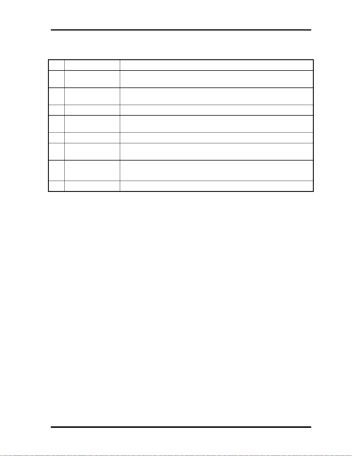
2. Messages when BD_ADDR is invalid are as follows:
Message Meaning
Invalid BD_ADDR (all 00) 0x000000000000
Invalid BD_ADDR (all FF) 0xFFFFFFFFFFFF
Invalid BD_ADDR (bit0=1) bit40=1b
Invalid BD_ADDR (bit1=1) bit41=1b
Invalid BD_ADDR (define in the file) BD_ADDR is the one already defined in the file.
If the machine detects a malfunction, it indicates the error code as shown below.
The error code begins with the least significant digit.
Error code
Table 3-2 Error code for NICSPC73.EXE (1/2)
Error code Meaning
0x01 Unknown HCI Command.
0x02 No Connection.
0x03 Hardware Failure.
0x04 Page Timeout.
0x05 Authentication Failure.
0x06 Key Missing.
0x07 Memory Full.
0x08 Connection Timeout.
0x09 Max Number Of Connections.
0x0a Max Number Of SCO Connections To A Device.
0x0b ACL Connection already exists.
0x0c Command Disallowed.
0x0d Host Rejected due to limited resources.
0x0e Host Rejected due to security reasons.
0x0f Host Rejected due to remote device is only a personal device.
0x10 Host Timeout.
0x11 Unsupported Feature or Parameter Value.
0x12 Invalid HCI Command Parameters.
0x13 Other End Terminated Connection: Used Ended Connection.
0x14 Other End Terminated Connection: Low Resources.
0x15 Other End Terminated Connection: About to Power Off.
0x16 Connection Terminated by Local Host.
0x17 Repeated Attempts.
0x18 Paring Not Allowed.
0x19 Unknown LMP PDU.
0x1a Unsupported Remote Feature.
0x1b SCO Offset Rejected.
0x1c SCO Interval Rejected.
0x1d SCO Air Mode Rejected.
0x1e Invalid LMP Parameters.
0x1f Unspecified Error.
** See the Specification of the Bluetooth System for details.
Portege M200 Maintenance Manual (960-457) 3-39
Page 11

3 Tests and Diagnostics 3.16 Bluetooth Test
Table 3-2 Error code for NICSPC73.EXE (2/2)
Error code Meaning
0x20 Unsupported LMP Parameter Value.
0x21 Role Change Not Allowed.
0x22 LMP Response Timeout.
0x23 LMP Error Transaction Collosion.
0x24 LMP PDU Not Allowed.
0x25 Not Exist
0x26 Not Exist
0x27 Not Exist
0x28 Not Exist
0x29 Not Exist
0x2a Not Exist
0x2b Not Exist
0x2c Not Exist
0x2d Not Exist
0x2e Not Exist
0x2f Not Exist
** See the Specification of the Bluetooth System in detail.
3-40 Portege M200 Maintenance Manual (960-457)
Page 12

3.16 Bluetooth Test 3 Tests and Diagnostics
NICSPC53.EXE
Follow the steps below to perform the test program, NICSPC53.EXE. This Program checks
the function. Refer to Section 2.17, Bluetooth Troubleshooting, for a detailed description of
the troubleshooting procedures for the Bluetooth.
1. Preparing the target machine for NICSPC53.EXE.
(b) Insert a floppy disk containing the test program into the target machine and
turn the target machine.
(c) Prompts are displayed as shown in figure 3-4, if it is the first time the program
has run.
The Program NICSPC53.EXE runs.
(d) When the machine is initializing, the following message is shown.
-----------------------------------------------------------------------------
Bluetooth Subsystem T&D for PCSE(CS-Air) VerX.XX Copyright (C) by TOSHIBA Co.
-----------------------------------------------------------------------------
+----------------------+
| DUT |
+----------------------+
Initializing …
Figure 3-4 Initializing for NICSPC53.EXE
Portege M200 Maintenance Manual (960-457) 3-41
Page 13

3 Tests and Diagnostics 3.16 Bluetooth Test
(e) When the test begins, the machine displays BD_ADDR of the DUT. The
progress bar stops when the test is completed. The following message is
shown.
-----------------------------------------------------------------------------
Bluetooth Subsystem T&D for PCSE(CS-Air) VerX.XX Copyright (C) by TOSHIBA Co.
-----------------------------------------------------------------------------
+----------------------+
| DUT | BD_ADDR of the DUT = XXXXXXXXXXXXX [h]
+----------------------+
Ready>>>>>>>>>>>>>>>>>>>>>> <- Progress Bar
[ESC] : Stop
Figure 3-5 BD_ADDR of the DUT is displayed
(f) When the machine has passed the test, it displays BD_ADDR of the DUT. If
the connection with the tester is completed, the progress bar stops. The
following message is shown.
-----------------------------------------------------------------------------
Bluetooth Subsystem T&D for PCSE(CS-Air) VerX.XX Copyright (C) by TOSHIBA Co.
-----------------------------------------------------------------------------
+----------------------+
| DUT | BD_ADDR of the DUT = XXXXXXXXXXXXX [h]
+----------------------+
CCCC OOO M M PPPPPP L EEEEEE TTTTTTT EEEEEEE DDDDD
C C O O MM MM P P L E T E D D
C O O M M M M P P L E T E D D
C O O M M M PPPPPP L EEEEEE T EEEEEEE D D
C O O M M P L E T E D D
C C O O M M P L E T E D D
CCCC OOO M M P LLLLLLL EEEEEE T EEEEEEE DDDDD
Testing is finished
A>_
Figure 3-6 Test completed
3-42 Portege M200 Maintenance Manual (960-457)
Page 14

3.16 Bluetooth Test 3 Tests and Diagnostics
(g) If the target machine has any problem, the following message shown in the
following figure ”INCOMPLETE” is displayed with the Error CODE.
-----------------------------------------------------------------------------
Bluetooth Subsystem T&D for PCSE(CS-Air) VerX.XX Copyright (C) by TOSHIBA Co.
-----------------------------------------------------------------------------
+----------------------+
| DUT | BD_ADDR of the DUT = XXXXXXXXXXXXX [h]
+----------------------+
III N N CCCC OOO M M PPPPPP L EEEEEE TTTTTTT EEEEEEE
I NN N C C O O MM MM P P L E T E
I N N N C O O M M M M P P L E T E
I N N N C O O M M M PPPPPP L EEEEEE T EEEEEEE
I N N N C O O M M P L E T E
I N NN C C O O M M P L E T E
III N N CCCC OOO M M P LLLLLLL EEEEEE T EEEEEEE
Testing is finished
A>_
Figure 3-7 Test incomplete (failure)
Portege M200 Maintenance Manual (960-457) 3-43
Page 15

3 Tests and Diagnostics 3.16 Bluetooth Test
If the machine detects a malfunction, it indicates the error code as shown below.
The error code begins with the least significant digit.
Error code
Table 3-3 Error code for
Error code Meaning
0x01 Unknown HCI Command.
0x02 No Connection.
0x03 Hardware Failure.
0x04 Page Timeout.
0x05 Authentication Failure.
0x06 Key Missing.
0x07 Memory Full.
0x08 Connection Timeout.
0x09 Max Number Of Connections.
0x0a Max Number Of SCO Connections To A Device.
0x0b ACL Connection already exists.
0x0c Command Disallowed.
0x0d Host Rejected due to limited resources.
0x0e Host Rejected due to security reasons.
0x0f Host Rejected due to remote device is only a personal
device.
0x10 Host Timeout.
0x11 Unsupported Feature or Parameter Value.
0x12 Invalid HCI Command Parameters.
0x13 Other End Terminated Connection: Uset Ended
Connection.
0x14 Other End Terminated Connection:Low Resources.
0x15 Other End Terminated Connection: About to Power
Off.
0x16 Connection Terminated by Local Host.
0x17 Repeated Attempts.
0x18 Paring Not Allowed.
0x19 Unknown LMP PDU.
0x1a Unsupported Remote Feature.
0x1b SCO Offset Rejected.
0x1c SCO Interval Rejected.
0x1d SCO Air Mode Rejected.
0x1e Invalid LMP Parameters.
0x1f Unspecified Error.
** See the Specification of the Bluetooth System for details.
NICSPC53.EXE (1/2)
3-44 Portege M200 Maintenance Manual (960-457)
Page 16

3.16 Bluetooth Test 3 Tests and Diagnostics
Table 3-3 Error code for NICSPC53.EXE (2/2)
Error code Meaning
0x20 Unsupported LMP Parameter Value.
0x21 Role Change Not Allowed.
0x22 LMP Response Timeout.
0x23 LMP Error Transaction Collosion.
0x24 LMP PDU Not Allowed.
0x25 Not Exist
0x26 Not Exist
0x27 Not Exist
0x28 Not Exist
0x29 Not Exist
0x2a Not Exist
0x2b Not Exist
0x2c Not Exist
0x2d Not Exist
0x2e Not Exist
0x2f Not Exist
** See the Specification of the Bluetooth System in detail.
Portege M200 Maintenance Manual (960-457) 3-45
Page 17

3 Tests and Diagnostics 3.17 Sound/LAN/Modem Test
3.17 Sound/LAN/Modem Test
To execute the Sound/LAN/Modem Test, use the Test Diagnostics disk
(Sound/LAN/Modem). Finish the tests of the Diagnostics disk (T&D) by selecting 99 - EXIT
TO DIAGNOSTICS MENU in the DIAGNOSTIC TEST MENU. Then in the
DIAGNOSTICS MENU, select 9 - EXIT TO MS-DOS.
NOTE: To execute the Tablet Dock CD Test, attach the computer to the Tablet Multi
Dock before turning on the computer.
Insert the Test program disk (Sound/LAN/Modem) in the floppy disk drive and turn on the
power. The following message will appear:
####################################################################
####### XXXX DIAGNOSTICS PROGRAM (SOUND/LAN/MODEM TEST) #######
####################################################################
* *
* 1 ............ (Microphoned recording&play Mic 2&4) *
* 2 ............ (Microphoned recording&play Mic 3&4) *
* 3 ............ (Sin Wave) *
* 4 ............ (LAN) *
* 5 ............ (MODEM) *
* 6 ............ (Tablet Dock CD TEST) *
********************************************************************
.... Press test number[1-6] ?
Press the number you want to test and press Enter.
NOTE: To record the sound from the specified microphone in Subtest 01, scratch each hole
of the microphones lightly with a sharp-pointed thing to make sure the specified
microphone catches the sound. The system is capable of producing high volume
sound, so when you use the headphones be careful to set the volume low and adjust it
as necessary. Using the headphones at full volume could damage your ears.
There are one microphone on the upper side of the LCD and two microphones on the lower
side. Microphone numbers are assigned as following.
Right upper side of the LCD -Mic 2
Left lower side of the LCD -Mic 3
Right lower side of the LCD -Mic 4
Subtest 01 Microphoned recording & play Mic 2&4
Executed by the load format of Playwave/recwave.
3-46 Portege M200 Maintenance Manual (960-457)
Page 18

3.17 Sound/LAN/Modem Test 3 Tests and Diagnostics
The sound is recorded automatically from microphone when the following
message appears.
Press any key to continue ...
After a while, the recorded sound is replayed automatically.
Subtest 02 Microphoned recording & play Mic 3&4
This subtest is executed in the same way as Microphoned recording & play
Mic 2&4.
Subtest 03 Sin wave
This subtest is executed by loading the COM file (ADSIN.COM.) The
program expands sin wave data table from 16KB to 64KB, and creates the
play data. Then it transfers the data between the DMA and the CODEC to
play the sin wave. (It sounds like a continuous beep.) By using wave
measuring devices such as an oscilloscope, the data can be measured as a sin
wave.
When the subtest is executed, the following message appears.
Press any key to continue....
When you press any key, the sin wave is expanded from 16KB to 64KB data
and is played.
The sound is heard and the test returns to the menu.
Subtest 04 LAN
This subtest checks the operation of mini-PCI I/F by the loopback in the chip.
The large “OK” is displayed if no error occurred.
Subtest 05 MODEM
For this subtest, connect the modem PCB and RJ11 connector with a harness.
This subtest contains the following tests. They are tested with the dedicated
“FAT-MODE inspection device(Product Code QE2000P01 made by Nittou
Denki Seisakusyo)
Scorpio Modem Initialize •
• Digital Loopback Test
Portege M200 Maintenance Manual (960-457) 3-47
Page 19

3 Tests and Diagnostics 3.17 Sound/LAN/Modem Test
Subtest 06 Tablet Dock CD TEST
NOTE: This subtest needs the test media (CD-R) created by wiring the data,
CDTEST.DAT, in the SOUND/LAN/MODEM disk (Test Diagnostics disc (No.2)). Also
before selecting this subtest, set the test media in the drive of the Tablet Dock.
This subtest compares the data of the test program and the data in the test
media to check whether the data from the drive can be read correctly.
When the test starts, the following message will appear.
TEST LOOP : Y=[Y], N=[N]..?
Select either (press Y or N) and press Enter.
When the message "OK" or "NO" appears, press Enter to return to the menu
screen.
To finish the Sound/LAN/Modem test, the computer power should be off.
3-48 Portege M200 Maintenance Manual (960-457)
Page 20

3.18 Thermal Radiation Control Test 3 Tests and Diagnostics
3.18 Thermal Radiation Control Test
This thermal radiation control test checks the temperature of the CPU and GPU. To execute
this test, use the diagnostics disk (Thermal radiation control) and follow the procedures
below.
1. Turn on the computer and start the Windows.
2. Insert the diagnostic disk for the thermal radiation control test to the USB FDD.
3. Open the [EXPLORE] window and double-click the [THERMAL.bat] file in the
diagnostic disk.
4. The input field appears on the screen. Then, input the temperature around the
computer and click [OK] button. The thermal radiation control test starts.
5. The display counting from 900 to 0 seconds (for 15 minutes) appears on the screen.
When the test ends normally, the following message appears in the display.
[Status:pass]
When an error is found, the following message appears in the display.
[Status:CPU:FAIL GPU:FAIL]
When the error message appears in the display, there is a possibility of breakage of
CPU, GPU or FAN.
NOTE: The display on the screen changes while executing this test. This is not an
error. Do not touch any key and keep executing the test, for this change applies
some load to CPU and GPU for the test.
Close the test menu to end the thermal radiation control test.
Portege M200 Maintenance Manual (960-457) 3-49
Page 21

3 Tests and Diagnostics 3.19 Error Status Code
3.19 Error Status Code
Table 3-4 lists the error status codes for the Diagnostic Test.
Table 3-4 Error status codes names (1/2)
Device name Error code Error status name
(Common) FF Data Compare Error
System
Memory
Keyboard
FDD
01
02
03
01
02
14
DD
DE
DF
01
02
03
04
05
06
01
02
03
04
06
08
09
10
20
40
60
80
EE
ROM Checksum Error
Location ID Error
Serial ID Writer Error
Parity error
Protected mode not change
Memory write/read error
Cache memory error
2nd Cache error
TAG-RAM error
Mouse interface error
IPS interface error
Interface error
Retransmit error
Mouse handler not support
PS/2 mouse & IPS not
Bad Command Error
Address Mark Not Found
Write Protected
Record Not Found
Media Removed
DMA Overrun Error
DMA Boundary Error
CRC Error
FDC Error
Seek Error
Not Drive Error
Time Out Error
Write Buffer Error
3-50 Portege M200 Maintenance Manual (960-457)
Page 22

3.19 Error Status Code 3 Tests and Diagnostics
Table 3-4 Error status codes names (2/2)
Device name Error code Error status name
HDD 01
02
04
05
07
08
09
0A
0B
10
11
20
40
80
AA
BB
CC
E0
EE
DA
PCMCIA
C1
C2
C3
C4
C5
C6
C7
C8
CB
CD
Bad Command Error
Address Mark Not Found
Record Not Found
HDC Not Reset Error
Drive Not Initialized
HDC overrun (DRQ)
DMA Boundary Error
Bad Sector
Bad Track Error
ECC Error
ECC recover error
HDC Error
Seek Error
Time Out Error
Drive Not Ready
Undefined Error
Write Fault
Status Error
Access Time Out Error
No HDD
ADDRESS LINE ERROR
REG# LINE ERROR
CE#1 LINE ERROR
CE#2 LINE ERROR
DATA LINE ERROR
WAIT LINE ERROR
BSY# LINE ERROR
BVD1 LINE ERROR
ZV Port ERROR
NO PCMCIA
NDP 01
02
03
04
05
06
No Co-Processor
Control Word Error
Status Word Error
Bus Error
Addition Error
Multiplay Error
Portege M200 Maintenance Manual (960-457) 3-51
Page 23

3 Tests and Diagnostics 3.20 HDC Status
3.20 HDC Status
When an error occurs in the hard disk test, the following message is displayed:
HDC status = XXXX
The hard disk test error status is displayed on the screen by a four-digit number.
The hard disk controller error status is composed of two bytes; the first byte displays the
contents of the HDC error status register and the second byte displays the HDC error register.
Each of them are indicated in hexadecimal form
The contents of the HDC error status register and error register are listed in Tables 3-5 and 3-
6.
Table 3-5 Hard disk controller status register contents
Bit Name Description
7 BSY
(Busy)
6 DRDY
(Drive ready)
5 DWF
(Drive write fault)
4 DSC
(Drive seek complete)
“0” … HDC is ready.
“1” … HDC is busy.
“0” … Hard disk drive is not ready to accept any command.
“1” … Hard disk drive is ready.
“0” … DWF error is not detected.
“1” … Write fault condition occurred.
“0” … The hard disk drive heads are not settled over a track.
“1” … The hard disk drive heads are settled over a track.
3 DRQ
(Data request)
2 CORR
(Corrected data)
1 IDX
(Index)
0 ERR
(Error)
“0” … Drive is not ready for data transfer.
“1” … Drive is ready for data transfer.
“0” … Not used
“1” … Correctable data error is corrected.
“0” … Not used
“1” … Index is sensed.
“0” … Not used
“1” … The previous command was terminated with an error.
3-52 Portege M200 Maintenance Manual (960-457)
Page 24
3.20 HDC Status 3 Tests and Diagnostics
Table 3-6 Error register contents
Bit Name Description
7 BBK
(Bad block mark)
6 UNC
(Uncorrectable)
5 —— Not used
4 IDN
(Identification)
3 —— Not used
2 ABT
(Abort)
1 TK0
(Track zero)
0 —— Not used.
“0” … Not used
“1” … A bad block mark is detected.
“0” … There is no uncorrectable data error.
“1” … Uncorrectable data error has been detected.
“0” … Not used
“1” … There was no ID field.
“0” … Not used
“1” … Illegal command error or a command abort error.
“0” … The hard disk detected track 0.
“1” … The hard disk could not detect track 0.
Portege M200 Maintenance Manual (960-457) 3-53
Page 25

3 Tests and Diagnostics 3.21 FDD Cleaning
3.21 FDD Cleaning
3.21.1 Function Description
This function cleans the heads in the 3.5-inch FDD by executing a series of head load/seek
and read operations. A cleaning disk is necessary to perform this program.
3.21.2 Operations
1. Selecting test 4-HEAD CLEANING from the DIAGNOSTIC MENU and pressing
Enter displays the following messages:
DIAGNOSTICS – FLOPPY DISK HEAD CLEANING : V6.00
Mount cleaning disk(s) on drive(s).
Press any key when ready.
2. Remove the Diagnostics Disk from the FDD, then insert the cleaning disk and press
Enter.
3. When the following message appears, the FDD head cleaning has begun.
Cleaning start
4. The display automatically returns to the DIAGNOSTIC MENU when the program is
completed.
3-54 Portege M200 Maintenance Manual (960-457)
Page 26

3.22 Log Utilities 3 Tests and Diagnostics
3.22 Log Utilities
3.22.1 Function Description
This function logs error information generated while a test is in progress and stores the
results in RAM. This function can also store data on a floppy disk or output the data to a
display or a printer.
If the power switch is turned off, the error information will be lost. The error information is
displayed in the following order:
1. Error count (CNT)
2. Test name, Subtest number (TS-No)
3. Pass count (PASS)
4. Error status code (STS)
5. FDD/HDD or memory address (ADDR)
6. Write data (WD)
7. Read data (RD)
8. HDC status code (HSTS)
9. Error status name (ERROR STATUS NAME)
Portege M200 Maintenance Manual (960-457) 3-55
Page 27

3 Tests and Diagnostics 3.22 Log Utilities
3.22.2 Operations
Selecting 5-LOG UTILITIES and pressing Enter in the DIAGNOSTIC MENU logs error
information into RAM or onto a floppy disk. The error information is displayed in the
following format:
0003 ERRORS
CNT TS-No PASS STS ADDR WD RD HSTS [ERROR STATUS NAME]
001 FDD 01 0000 110 24015 00 00 FDD-CRC ERROR
002 FDD 01 0001 110
003 FDD 03 0003 110
30108 00 00 FDD-CRC ERROR
23106 00 00 FDD-CRC ERROR
[[1:Next,2:Prev,3:Exit,4:Clear,5:Print,6:FD Log Read,7:FD Log Write]]
2. The error information displayed on the screen can be manipulated by the following
number keys:
The 1 key scrolls the display to the next page.
The 2 key scrolls the display to the previous page.
The 3 key returns to the Diagnostic Menu.
The 4 key erases all error log information in RAM.
The 5 key outputs the error log information to a printer.
The 6 key reads the log information from a floppy disk.
The 7 key writes the log information to a floppy disk.
3. In the case of “error retry OK”, a capital “R” will be placed at the beginning of the
error status. However, it is not added to the error count.
3-56 Portege M200 Maintenance Manual (960-457)
Page 28

3.23 Running Test 3 Tests and Diagnostics
3.23 Running Test
3.23.1 Function Description
This function automatically executes the following tests in sequence:
1. System test (subtest 01)
2. Memory test (subtests 01, 02, 04, 06)
3. Real timer test (subtest 02)
4. Display test (subtest 01)
5. FDD test (subtest 02)
6. HDD test (subtests 01, 05)
The system automatically detects the number of floppy disk drives connected to the computer
for the FDD test.
3.23.2 Operations
Caution: Do not forget to remove the diagnostics disk and load a formatted work disk in
the FDD. If a work disk is not loaded, an error will be generated during the FDD testing.
1. Remove the diagnostics disk from the floppy disk drive and insert the formatted work
disk.
2. Select 6-RUNNING TEST from the DIAGNOSTIC MENU and press Enter. The
following message is displayed.
Printer wrap around test (Y/N) ?
Select Y (yes) to execute the Printer wraparound test or N (NO) not to execute, then
press Enter. A printer wraparound connector must be connected to the parallel port
of the computer to execute properly this test.
3. When the selecting of the Printer wraparound test is completed, the following
message is displayed.
Serial #A wrap around test (Y/N) ?
Select Y (yes) to execute the Serial #A test or N (NO) not to execute, then press
Enter. A RS-232C wraparound connector must be connected to the serial port of the
computer to execute properly this test.
Portege M200 Maintenance Manual (960-457) 3-57
Page 29

3 Tests and Diagnostics 3.23 Running Test
4. After specifying of the Serial #A test, the following message will appear:
Mount the work disk(s) on the drive(s),
then press [Enter] key.
[Warning : The contents of the disk(s),
will be destroyed.]
5. This program is executed in the above mentioned ways. To exit the program, press
Ctrl + Break.
3-58 Portege M200 Maintenance Manual (960-457)
Page 30

3.24 Floppy Disk Drive Utilities 3 Tests and Diagnostics
3.24 Floppy Disk Drive Utilities
3.24.1 Function Description
This function formats the FDD, copies the floppy disk and displays the dump list for both the
FDD and HDD.
1. FORMAT
Caution: This program is only for testing a floppy disk drive. The option is different from
the MS-DOS FORMAT command.
This program formats the floppy disk in the following formats.
(a) 2DD: Double-sided, double-density, double-track, 96/135 TPI, MFM mode,
512 bytes, 9 sectors/track.
(b) 2HD: Double-sided, high-density, double-track, 96/135 TPI, MFM mode, 512
bytes, 18 sectors/track.
2. COPY
This program copies data from a source floppy disk to a target floppy disk.
3. DUMP
This program displays the contents of the floppy disk and the designated sectors of
the hard disk.
4. HDD-ID
This program reads the hard disk ID and displays the hard disk ID, serial number and
other hard disk information.
Portege M200 Maintenance Manual (960-457) 3-59
Page 31

3 Tests and Diagnostics 3.24 Floppy Disk Drive Utilities
3.24.2 Operations
1. Selecting 7-FDD UTILITIES from the DIAGNOSTIC MENU and pressing Enter
displays the following message:
[ FDD UTILITIES ]
1 - FORMAT
2 - COPY
3 - DUMP
4 - HDD-ID
9 - EXIT TO DIAGNOSTICS MENU
2. FORMAT program
(a) When FORMAT program is loaded, the following message is displayed:
DIAGNOSTICS - FLOPPY DISK FORMAT : V6.00
Drive number select (1:A, 2:B) ?
(b) Select a drive number to display the following message:
Type select (0:2DD, 3:2HD) ?
(c) Select a media/drive type number and press Enter. The following message
will be displayed:
Warning : Disk data will be destroyed.
Insert work disk into drive A:
Press any key when ready.
(d) Remove the Test program Disk from the FDD, insert the work disk and press
any key. The following message will be displayed and the FDD format is
executed:
[ FDD TYPE ] : TRACK = XXX
[ FDD TYPE ] : HEAD = X
[ FDD TYPE ] : SECTOR = XX
Format start
[[track, head = XXX X]]
After the floppy disk is formatted, the following message will appear:
Format complete
Another format (1:Yes/2:No) ?
(e) Typing 1 displays the message from step (c) above. Typing 2 returns the test
to the DIAGNOSTIC MENU.
3-60 Portege M200 Maintenance Manual (960-457)
Page 32

3.24 Floppy Disk Drive Utilities 3 Tests and Diagnostics
3. COPY program
(a) When FORMAT program is loaded, the following message is displayed:
FLOPPY DISK FORMAT & COPY : V6.00
Type select (0:2DD,3:2HD) ?
(b) Selecting a media/drive type number will display a message below:
Insert source disk into drive A:
Press any key when ready.
(c) Remove the Diagnostics Disk from the FDD, insert the source disk and press
any key. The following message appears and copying of the disk starts.
[ FDD TYPE ] : TRACK = XXX
[ FDD TYPE ] : HEAD = X
[ FDD TYPE ] : SECTOR = XX
Copy start
[[ track,head = XXX X ]]
(d) Remove the source disk from the FDD, insert a formatted work disk and press
any key. The following message will appear and start copying to the target
disk.
Insert target disk into drive A:
Press any key when ready.
[[ track,head = XXX X ]]
(e) When the amount of data is too large to be copied in one operation, the
message from step (b) is displayed again. After the floppy disk has been
copied, the following message will appear:
Copy complete
Another copy (1:Yes/2:No) ?
(f) To copy another disk, type 1 and the message from step (a) is displayed again.
Entering 2 returns the test program to the DIAGNOSTIC MENU.
Portege M200 Maintenance Manual (960-457) 3-61
Page 33

3 Tests and Diagnostics 3.24 Floppy Disk Drive Utilities
4. DUMP program
(a) When DUMP program is loaded, the following message appears:
DIAGNOSTICS-HARD DISK & FLOPPY DISK DUMP : V7.00
Drive type select (1:FDD, 2:HDD) ?
(b) Select a format type number. If 2:HDD is selected, the display will go to step
(h).
If 1:FDD is selected, the following message appears:
Select drive number (1:A, 2:B) ?
(c) Select a drive number and the following message will be displayed.
Format type select (1:2DD, 2:2HD) ?
(d) Select a format type and the following message will appear:
2HD media mode (1:1.20MB,2:1.44MB,3:1.23MB) ?
(e) Select a media mode and the following message will appear:
Insert source disk into drive A:
Press any key when ready.
(f) Insert a source disk and press any key and the following message will appear:
—— Max. address ——
[Track ] = XXXX
[ Head ] = XX
[Sector] = XX
Track number ????
(g) Select the track number, the head number and the sector number you want to
dump. The system will access the disk and dump a list. Then the message
shown in (k) will appear.
(h) The following message will appear.
Select drive number (1:C, 2:D) ?
(i) Select a drive number and the following message will be displayed.
—— Max. address ——
[LBA ] = XXXXXXXXX
LBA number ??
(j) Set the LBA number you want to dump. The system will access the disk and
dump a list.
3-62 Portege M200 Maintenance Manual (960-457)
Page 34

3.24 Floppy Disk Drive Utilities 3 Tests and Diagnostics
(k) The following message will appear. To finish the dump, select 3.
Press number key (1:up, 2:down, 3:end) ?
(l) The following message will appear. Selecting 2 returns to the FDD
UTILITIES MENU.
Another dump (1:Yes, 2:No) ?
Portege M200 Maintenance Manual (960-457) 3-63
Page 35

3 Tests and Diagnostics 3.24 Floppy Disk Drive Utilities
5. HDD-ID READ program
Loading HDD ID READ program displays the following HDD ID configuration:
[HDD ID Read (VX.XX)] [Drive #X]
ID code (h) = XXXX
No. of Cylinders = XXXXXXXX
Removable Cylinders = XXXXXXXX
No. of Heads = XXXXXXXX
Unformat Bytes/Track = XXXXXXXX
Unformat Bytes/Sector = XXXXXXXX
Sectors/Track = XXXXXXXX
Gap Length = XXXXXXXX
Sync. Bytes = XXXXXXXX
Reserved (h) = XXXX
Serial No. = YYY...
Controller Type (h) = XXXX
Sector Buffers = XXXXXXXX
ECC Bytes = XXXXXXXX
Firmware Rev. = YYYYYY..
Model No. = YYYY...
Reserved (h) = XXXX
Double Word Capability = XXXXXXXX
Press [Enter] key
Press Enter to return to the FDD UTILITIES MENU.
3-64 Portege M200 Maintenance Manual (960-457)
Page 36

3.25 System Configuration 3 Tests and Diagnostics
3.25 System Configuration
3.25.1 Function Description
The System Configuration program contains the following configuration information for the
computer:
1. Processor Type
2. VGA Controller
3. MS-DOS Version
4. BIOS ROM version (1st ID, 2nd ID)
5. BOOT ROM version
6. KBC version
7. PS Micon Version
8. Total Memory Size
9. Battery Code
10. Sound System
11. The number of printer adapters
12. The number of ASYNC adapters
13. The number of Co-processors
14. The number of PCMCIA Slots
15. Modem Type
16. LAN Type
17. The number of FDDs
18. The number of HDDs
19. Date/Time
Portege M200 Maintenance Manual (960-457) 3-65
Page 37

3 Tests and Diagnostics 3.25 System Configuration
3.25.2 Operations
1. Selecting
8-SYSTEM CONFIGURATION from the DIAGNOSTIC MENU and pressing
Enter displays the following system configuration:
System Configuration Display : Ver X.XX [Machine Name : XXXX ]
** - Processor Type = XX – XXXXX
** - VGA Controller = xxxx
* - MS-DOS Version = Vxxxx
* - BIOS-ROM Version = Vxxxx 1st ID = XXH, 2nd ID = XXH
* - BOOT-ROM Version = Vxxxx
* - KBC Version = Vxxxx
* - PS Micom Version = Vxxxx (EC Version = VX.XX)
* - Total Memory Size = xxxxxMB(Conventional Memory = 00639KB)
* - Battery Code =
** - Sound System = XXXXX
* - 0 Printer Adapter LPT1= LPT2= LPT3=
* - 0 ASYNC Adapter COM1= COM2= COM3=
* -
* - 1 Math Co-Processor
* - 1 PCMCIA Slot
* - Modem = MDC (AS KEY)
* - LAN = Kinnerth
* X Floppy Disk Drive(s) Tracks=XX, Head=XX, Section=XX
* - 1 Hard Disk Drive(s) #1 Sectors = XXXXXXXXXX (XXXXXMB)
#2 Sectors = ( MB)
* -
Press [Enter] Key [Date = YYYY-MM-DD, HH:MM:SS]
2. Press Enter to return to the DIAGNOSTIC MENU.
3-66 Portege M200 Maintenance Manual (960-457)
Page 38

3.26 SETUP 3 Tests and Diagnostics
3.26 SETUP
3.26.1 Function Description
This program displays the current system setup information as listed below:
1. Memory
(a) Total
2. System Date/Time
(a) System Date
(b) System Time
3. Battery
4. Password
5. HDD Password
(a) HDD
(b) HDD Password Mode
(c) User Password
(d) Master Password
6. Boot Priority
(a) Boot Priority
(b) HDD Priority
(c) Network Boot Protocol
7. Display
(a) Power On Display
(b) LCD Display Stretch
8. Others
(a) CPU Cache
(b) Level 2 Cache
(c) Dynamic CPU Frequency Mode
(d) Auto Power On
9. Configuration
10. Drives I/O
(a) Built-in HDD
(b) PC Card
11. PCI bus
12. PC Card
13. Peripheral
(a) Internal Pointing Device
(b) Hard Disk Mode
14. Legacy Emulation
(a) USB KB/Mouse Legacy Emulation
Portege M200 Maintenance Manual (960-457) 3-67
Page 39

3 Tests and Diagnostics 3.26 SETUP
(b) USB-FDD Legacy Emulation
15. PCI LAN
16. SD
3-68 Portege M200 Maintenance Manual (960-457)
Page 40

3.26 SETUP 3 Tests and Diagnostics
SYSTEM SETUP (1/2)
ACPI BIOS version = X.XX
d
)
3.26.2 Accessing the SETUP Program
Selecting 0-SETUP from the DIAGNOSTICS MENU and pressing Enter displays the
followings:
MEMORY
Total = XXXXX KB
SYSTEM DATE/TIME
System Date =XX-XX-XXXX
System Time =XX:XX:XX
BATTERY
Battery Save Mode = Full Power
PASSWORD
Not Registered
HDD PASSWORD
HDD = Built-in HDD
HDD Password Mode = User Only
User Password = Not Registered
Master Password = Not Registered
(*1)
BOOT PRIORITY
Boot Priority =HDD→FDD→CD-ROM→LAN
HDD Priority =Built-in HDD→PC card
Network Boot Protocol = PXE
DISPLAY
Power On Display = Auto-Selected
LCD Display Stretch = Enabled
Others
CPU Cache = Enabled
Level 2 Cache = Enabled
Dynamic CPU Frequency Mode
= Dynamically
Switchable
Auto Power On = Disabled
↑↓→←: Select items Space, BkSp: Change values PgDn, PgUp: Change pages
Esc: Exit without saving Home : Set default values End: Save changes and Exit
CONFIGURATION
Device Config. = Setup by OS
Controller Mode = Auto-Selected
PC CARD
PERIPHERAL
Internal Pointing Device = Enable
Hard Disk Mode = Enhanced IDE(Normal
DRIVERS I/O
Built-in HDD = Primary IDE(1F0H/IRQ14)
PC Card = Others (190H/IRQ3)
PCI BUS
PCI BUS = IRQ10, IRQ11
LEGACY EMULATION
USB KB/Mouse Legacy Emulation
USB-FDD Legacy Emulation =
= Enabled
PCI LAN
Built-in LAN = Enabled
SD
SD Controller = Enabled
↑↓→←: Select items Space, BkSp: Change values PgDn, PgUp: Change pages
Esc: Exit without saving Home : Set default values End: Save changes and Exit
Enabled
NOTE: (*1) This depends on model.
Portege M200 Maintenance Manual (960-457) 3-69
Page 41

3 Tests and Diagnostics 3.26 SETUP
Moving Within the SETUP Menu and Changing Values
1. Press Å and Æ to move between the columns horizontally. Press ↑ and ↓ to move
between items in a column. Press Fn+↑ (PgUp) and Fn + ↓ (PgDn) to move
between the two pages.
2. Press either the Space bar or Back Space to change the value.
Accepting Changes and Exiting the SETUP Window
1. Press End to accept the changes you made.
If the changed item does not require the system to reboot, the following message is
displayed:
Are you sure? (Y/N)
If the changed item requires the system to reboot, the following message is displayed:
Are you sure? (Y/N)
The changes you made will cause the system to reboot.
2. To make other changes, press N. Repeat the steps above.
3. To accept the changes, press Y.
NOTE: You can press Esc to quit at any time without saving changes. SETUP asks you
to confirm that you do not want to save your changes. When SETUP is displayed at the
next time, the current configuration appears.
The Factory Preset Configuration
When you access SETUP, the current configuration is displayed.
1. To display the factory preset configuration, press Home.
2. To accept the default settings, press End and then press Y.
NOTE: When you execute the default setting, the following settings are not changed:
(1) HDD mode
(2) Password
(3) Write Policy
3-70 Portege M200 Maintenance Manual (960-457)
Page 42

3.26 SETUP 3 Tests and Diagnostics
SETUP Options
The SETUP screen is divided into 16 functionally related groups. This section describes each
group and its option.
1. Memory
(1) Total
This field displays the total amount of memory installed and it is automatically
calculated by the computer. You cannot change this value.
2. System Date/Time
(a) System Date/Time
Use this option to set the date (month-day-year).
(b) System Date/Time
Use this option to set the time (hour : minute).
3. Battery
This option is used to select Full Power, Low Power or User Setting of the battery
save mode. When you select the battery save mode, the followings will appear.
Full Power The following shows full power settings.
BATTERY SAVE OPTIONS
Processing Speed = High
CPU Sleep Mode = Enabled
Display Auto off = 30Min.
HDD Auto off = 30Min.
LCD Brightness = Bright (*1)
Super-Bright (*2)
Cooling Method = Maximum Performance
Low Power The following shows low power settings.
BATTERY SAVE OPTIONS
Processing Speed = Low
CPU Sleep Mode = Enabled
Display Auto off = 03Min.
HDD Auto off = 03Min.
LCD Brightness = Semi-Bright (*1)
Bright (*2)
Cooling Method = Battery Optimized
Portege M200 Maintenance Manual (960-457) 3-71
Page 43

3 Tests and Diagnostics 3.26 SETUP
NOTE: Display of the LCD Brightness will be changed in the condition below:
(*1) Operating the battery
(*2) Using the AC adapter
User Setting Use this option to set the battery save parameters on
the sub-window, BATTERY SAVE OPTIONS. For
details, see Battery Save Options below.
Battery Save Options
Processing Speed
This feature changes the CPU processing speed.
High CPU operates at 1.4/1.5/1.6/1.7GHz (Pentium-M)
(Default in Full Power Mode)
Low CPU operates at half processing speed.
(Default in Low Power Mode)
CPU Sleep Mode
Use this option to enable or disable the CPU sleep function.
Enabled Enables sleep mode. (Default)
Disabled Disables sleep mode.
Display Auto Off
Use this option to disable or set the duration of the display automatic power off
function. This function causes the computer to turn the LCD panel’s illumination off
if you make no entry (including no operation of a tablet pen or touch pad) for the set
period of time.
Disabled Disables display automatic power off.
xx Min. Automatically turns off the power to the LCD panel’s
illumination if the panel is not used for the duration set.
The duration xx can be set to 1, 3, 5, 10, 15, 20 or 30
minutes.
HDD Auto Off
Use this option to set the duration of the HDD automatic power off function. This
option stops the rotation of the HDD if you do not read or write to the HDD more
than the duration set.
xx Min. Automatically turns off the power to the hard disk drive
if it is not used for the duration set. The duration xx
can be set to 1, 3, 5, 10, 15, 20, 30 minutes or Disabled.
3-72 Portege M200 Maintenance Manual (960-457)
Page 44

3.26 SETUP 3 Tests and Diagnostics
LCD Brightness
Use this option to set the level of LCD brightness.
Super-Bright Full brightness for maximum visibility.
Bright Full brightness for high visibility.
Semi-Bright Less than full brightness for saving power.
Cooling Method
Maximum Performance If the CPU becomes too hot, the fan turns on
automatically in a high speed to cool down the CPU.
Performance If the CPU becomes too hot, the fan turns on
automatically. When the CPU temperature falls to a
normal range, the fan turns off.
Battery optimized If the CPU becomes too hot, the processing speed is
lowered. If the temperature is still too high, the fan turns
on. When the CPU temperature falls to a normal range,
the fan is turned off and the processing speed is
increased.
NOTE: Too hot condition may cause defect on the CPU. When the hot condition
continues, the power is automatically turned off in resume mode.
4. Password
When the incorrect password is continuously entered three times, the cursor does not
move to this option. In this case, reboot the computer and register the password again.
Registered The user password has been registered.
Not registered The user password has not been registered.
For details on setting the user password, refer to the User’s Manual.
5. HDD Password
NOTE: The contents of this option cannot be changed when the setup is started
from the test program.
(1) HDD
This option specifies the HDD to which the password is set. The built-in HDD is
specified and you cannot change it.
Portege M200 Maintenance Manual (960-457) 3-73
Page 45

3 Tests and Diagnostics 3.26 SETUP
(2) HDD Password Mode
This option selects the type of HDD password you want to register. You can
select the type when any HDD passwords (user HDD password or master HDD
password) are not set. If any HDD password is set, cancel it and select the type.
User Only Only the user password is registered. (Default)
Master+User Both the master password and the user password are registered.
(3) User Password
Use this option to set the user password.
(4) Master Password
This option appears when "HDD Password mode" is set to "Master+User".
Set the master password first and then set the user password.
6. Boot Priority
(a) Boot Priority
Use this option to set the priority for booting of the computer and the priority
for the HDD for booting.
FDD→HDD→CD-ROM→LAN: The computer looks for bootable files in
HDD→ CD-ROM→LAN→FDD:The computer looks for bootable files in
FDD→ CD-ROM→LAN→HDD: The computer looks for bootable files in
CD-ROM→LAN→HDD→FDD: The computer looks for bootable files in
CD-ROM→LAN→FDD→HDD: The computer looks for bootable files in
HDD→FDD→ CD-ROM→LAN:The computer looks for bootable files in
(*1) The FDD is looked for when the boot disk is contained in the external
FDD. When an SD memory card is set as the boot disk, the external FDD is
looked for first. Next, the SD memory card is looked for.
the following order: FDD (*1), HDD (*2),
CD-ROM (*3) and LAN
the following order: HDD, CD-ROM,
LAN and FDD.
the following order: FDD, CD-ROM, LAN
and HDD.
the following order: CD-ROM, LAN,
HDD and FDD.
the following order: CD-ROM, LAN, FDD
and HDD.
the following order: HDD, FDD, CD-ROM
and LAN. (Default)
3-74 Portege M200 Maintenance Manual (960-457)
Page 46

3.26 SETUP 3 Tests and Diagnostics
(*2) The HDDs are looked for in the order specified in "HDD Priority".
(*3) The CD-ROM is available only with the optional optical disk drive.
(b) HDD Priority
Use this option to set the priority for booting the computer from the HDD.
Built-in HDD -> PC Card The computer will look for the built-in HDD
first, next the PC card. (Default)
PC Card -> Built-in HDD The computer will look for the PC card first,
next the built-in HDD.
(c) Network Boot Protocol
Use this option to set the starting method via a network.
PXE Sets to PXE protocol. (Default)
RPL Sets to RPL protocol.
7. Display
This group of options configures the computer’s display.
(a) Power On Display
This option is used to select the display when booting up.
Auto-Selected Selects an external monitor if one is connected.
Otherwise it selects the internal LCD. (Default)
LCD+Analog RGB Selects both the internal LCD and the external CRT for
simultaneous display.
System LCD only Selects the internal monitor even if the external LCD is
connected.
NOTE: When LCD+Analog RGB is selected while connecting the external
display not corresponding to SVGA mode, no image appears on the display.
(b) LCD Display Stretch
LCD Display Stretch enables or disables a larger display area of the screen.
Enabled Enables the LCD display stretch feature. (Default)
Disabled Disables the LCD display stretch feature.
Portege M200 Maintenance Manual (960-457) 3-75
Page 47

3 Tests and Diagnostics 3.26 SETUP
8. Others
Whether or not you need to configure the computer with these options depends
primarily on the kind of software or peripherals you use.
(a) CPU Cache
Use this option to enable or disable the CPU cache.
Enabled Enables the CPU cache. (Default)
Disabled Disables the CPU cache.
When "Enabled" is selected, the following subwindow is displayed to select
the cache write policy. The options for this setting are Write-back (default)
and Write-through for CPU cache.
OPTION
Write policy = Write-back
Write-back policy provides better system performance, because main memory
is accessed only when necessary to update the cache contents with changes in
main memory. Write-through policy accesses main memory every time data is
handled by the processor.
(b) Level 2 Cache
Use this option to enable or disable the level 2 cache. When "CPU Cache" is
set to "Disabled", this option cannot be changed.
Enabled Enables the level 2 cache. (Default)
Disabled Disables the level 2 cache.
(c) Dynamic CPU Frequency mode
Use this option to choose a setting from the followings.
Dynamically Switchable
Enables Intel SpeedStep technology. When the
computer is in use, CPU power consumption and clock
speed are automatically switched when necessary.
(Default)
Always High Disables Intel SpeedStep technology and always runs
the processor at its fastest speed.
3-76 Portege M200 Maintenance Manual (960-457)
Page 48

3.26 SETUP 3 Tests and Diagnostics
A
Always Low Disables Intel SpeedStep technology and always runs
the processor at low power consumption and low speed
(d) Auto Power On
This option displays setting for Wake-up on LAN.
Disabled Indicates auto power on and Wake-up on LAN is not set.
Enabled Indicates auto power on and Wake-up on LAN is set.
When “Enabled” is set, the following subwindow appears.
Auto power on and Wake-up on LAN is set in the options subwindow. To set
alarm time, use Space and BackSpace. To switch between time and
minute, month and date, use ↑ and ↓.
OPTION
larm Time = 00:00:00
Alarm Date Option = Disabled
Wake-up on LAN = Disabled
Alarm Time sets a time and date for automatic power on. Second cannot be
set. When this option is set to “Disabled”, the time for automatic power on is
not set.
Alarm Date Option sets a month and date in order for automatic power on.
When Alarm Time is set to “Disabled”, month and date for automatic power
on is not set.
Wake-up on LAN automatically turn on the computer when accessed by the
administrator of LAN. When Built-in LAN is “Enabled”, this option can be
set to “Enabled”. AC adapter is required for this option.
NOTE: 1. Do not remove the AC adapter and battery pack at the same time when you
use this feature. If you do so, data saved by the resume function will be lost.
You must also reset this option.
2. If you have set a password and the computer starts up by the Auto Power On
function from the hibernation condition, the message “password =” is
displayed. Enter the password to return to the Windows screen from the
hibernation condition.
3. This option is enabled only once, the setting is reset, after booting up
Portege M200 Maintenance Manual (960-457) 3-77
Page 49

3 Tests and Diagnostics 3.26 SETUP
9. Configuration
This option lets you set the device configuration.
All Devices BIOS sets all devices.
Setup by OS Operating system sets devices that it can control.
(Default)
NOTE: When using installed OS, selecting “Set by OS” is recommended. But, when
setting “PC CARD-Controller Mode” to other than “ Auto-Selected”, select “ All
Devices”.
10. Drives I/O
(a) Built-in HDD
This option displays setting for hard disk drive. It is for information only and
cannot be changed.
(b) PC Card
This option displays the interruption level of the PC card HDD. The setting
cannot be changed.
11. PCI Bus
This option displays the interrupt level for the Card Bus in the computer. It is for
information only and cannot be changed.
12. PC Card
This option displays the PC Card Controller mode. When “Device Config.” is set to
“All Devices”, it can be changed.
Auto-Selected Use this setting when OS supports Plug&Play. (Default)
Card Bus/16-bit Use this setting when PC card which supports Cared Bus
does not work properly in “Auto-Selected”.
PCIC Compatible Use this setting when 16-bit PC card does not work
properly in “Auto-Selected” or "CardBus/16-bit".
3-78 Portege M200 Maintenance Manual (960-457)
Page 50

3.26 SETUP 3 Tests and Diagnostics
13. Peripheral
This option set the HDD and other devices.
(1) Internal Pointing Device
Use this option to set whether the touch pad is available or not.
Enabled Enables touch pad. (Default)
Disabled Disables touch pad.
(2) Hard Disk Mode
Use this item to select the hard disk mode.
Enhanced IDE (Normal) Select this mode when the HDD is used for
Windows XP Tablet PC Edition. (Default)
Standard IDE Select this mode when using an OS which does not
support the Enhanced IDE. When this mode is
selected, up to 528MB is logically available and the
rest of the capacity is not usable.
NOTE: Formats for Enhanced IDE and Standard IDE are different, so if you
change the setting, you will have to reformat the hard disk for the appropriate
setting.
14. Legacy Emulation
(a) USB KB/Mouse Legacy Emulation
This option sets the legacy support condition of the USB keyboard and the
USB mouse.
Enabled Enables legacy support. (Default)
Disabled Disables legacy support
USB keyboard and USB mouse are available without the driver.
Portege M200 Maintenance Manual (960-457) 3-79
Page 51

3 Tests and Diagnostics 3.26 SETUP
(b) USB-FDD Legacy Emulation
This option sets the Legacy support condition of the USB floppy disk drive.
Enabled Enables LEGACY support. (Default)
USB floppy disk is available without the driver.
To start the computer by FD, set this option to "Enabled".
Disabled Disables legacy support
15. PCI LAN
This option sets the Enable / Disable of the built-in LAN functions.
Enabled Enables built-in LAN functions. (Default)
Disabled Disables built-in LAN functions.
16. SD
This option sets the Enable / Disable of the SD controller functions.
Enabled Enables SD controller functions. (Default)
Disabled Disables SD controller functions.
3-80 Portege M200 Maintenance Manual (960-457)
Page 52

3.1 The Diagnostic Test 3 Tests and Diagnostics
3 Tests and Diagnostics
3.1 The Diagnostic Test
This chapter explains how to use the Diagnostic Test program which tests the functions of
the computer’s hardware modules and the Hardware Initial information Setting Tool which
sets the configurations needed after repairing.
The Diagnostic Test Program is grouped into the Service Program Modules and the Test
Program Modules. The Diagnostic Test consists of 10 programs. Wireless LAN test,
Sound/LAN/modem test and Bluetooth test are also supported.
The Hardware Initial information Setting Tool consists of some programs which writes the
hardware information or displays the current information of the computer.
NOTE: To start the diagnostics, follow these steps:
1. Check all cables for loose connections.
2. Exit any application and close Windows.
3.1.1 Diagnostics menu
The DIAGNOSTICS MENU consists of the following 7 test programs.
DIAGNOSTIC TEST
HEAD CLEANING
LOG UTILITIES
RUNNING TEST
FDD UTILITIES
SYSTEM CONFIGURATION
SETUP
The DIAGNOSTIC TEST MENU contains the following 10 functional tests:
SYSTEM TEST
MEMORY TEST
KEYBOARD TEST
DISPLAY TEST
FLOPPY DISK TEST
ASYNC TEST
HARD DISK TEST
REAL TIMER TEST
NDP TEST
EXPANSION TEST
Other tests are as follows.
3-1 Portege M200 Maintenance Manual (960-457)
Page 53

3 Tests and Diagnostics 3.1 The Diagnostic Test
WIRELESS LAN TEST
SOUND/LAN/MODEM TEST
BLUETOOTH TEST
You will need the following equipment to perform some of the Diagnostic test programs.
The Diagnostics Disk (all tests, 5 disks (T&D, Sound/LAN/modem, Wireless LAN,
Bluetooth, Thermal radiation control))
A USB floppy disk drive (all tests)
A formatted working disk (Floppy disk test)
A cleaning kit to clean the floppy disk drive heads (FDD Head Cleaning)
A RS-232C wraparound connector (ASYNC test)
A PC card wraparound connector (Expansion test)
An external CRT monitor (Expansion test)
A USB test module (Keyboard test)
A USB cable (Keyboard test)
Headphone (Sound/LAN/modem test)
A microphone (Sound/LAN/modem test)
FAT-MODE inspection device (Sound/Modem /LAN test)
A test media (Sound/Modem /LAN test)
A LAN wraparound connector (Expansion test)
Bidirectional machine for wraparound test
3.1.2 H/W (Hardware) initial information setting tool
The H/W initial information setting tool consists of the following 3 programs.
Initial configuration
System configuration display
Digitizer FW write
E2PROM test (MAC/DMI)
You will need the following equipment to perform some of the programs.
The Diagnostics Disk (all test (T&D))
A USB floppy disk drive (all tests)
A LAN wraparound connector (E2PROM test)
3-2 Portege M200 Maintenance Manual (960-457)
Page 54

3.2 Executing the Diagnostic Test 3 Tests and Diagnostics
3.2 Executing the Diagnostic Test
To start the DIAGNOSTIC PROGRAM, follow these steps:
1. Insert the test program disk (No.1) in the floppy disk drive.
2. Release the lock of the power switch and turn on the computer by pressing the F12.
Select the FDD in the display for selecting booting unit. Then press Enter and the
following menu appears:
1. Repair Main (T&D)
2. Repair initial config set
Enter a choice: 1
To start the Diagnostics menu (T&D), press 1 and Enter.
To start the H/W initial information setting tool, press 2 and Enter.
3.2.1 Diagnostics menu (T&D)
The following menu appears.
TOSHIBA personal Computer XXXX DIAGNOSTICS
version XXX (c) Copyright TOSHIBA Corp. 20XX
DIAGNOSTICS MENU :
1 - DIAGNOSTIC TEST
2 –
3 -
4 - HEAD CLEANING
5 - LOG UTILITIES
6 - RUNNING TEST
7 - FDD UTILITIES
8 - SYSTEM CONFIGURATION
9 - EXIT TO MS-DOS
0 – SETUP
Portege M200 Maintenance Manual (960-457) 3-3
Page 55

3 Tests and Diagnostics 3.2 Executing the Diagnostic Test
NOTE: To exit the DIAGNOSTIC TEST MENU, press the Esc. If a test program is in
progress, press Ctrl+Break to exit the test program. If a test program is in progress,
press Ctrl+C to stop the test program.
Set the highlight bar to 1, and press Enter. The following TEST MENU will appear:
TOSHIBA Personal Computer XXXX DIAGNOSTICS
Version XXX (c) Copyright TOSHIBA Corp. 20XX
DIAGNOSTIC TEST MENU :
1 - SYSTEM TEST
2 - MEMORY TEST
3 - KEYBOARD TEST
4 - DISPLAY TEST
5 - FLOPPY DISK TEST
6 -
7 – ASYNC test
8 - HARD DISK TEST
9 - REAL TIMER TEST
10 - NDP TEST
11 - EXPANSION TEST
12 -
13 –
14 –
88 - ERROR RETRY COUNT SET [FDD & HDD]
99 - EXIT TO DIAGNOSTICS MENU
Functions 1 through 14 are the Diagnostic Tests. Function 88 sets the floppy disk drive and
hard disk drive error retry count (0-255).
To return to the Diagnostics Menu, set the highlight bar to Function 99 and press Enter.
3-4 Portege M200 Maintenance Manual (960-457)
Page 56

3.2 Executing the Diagnostic Test 3 Tests and Diagnostics
Select the option you want to execute on the test menu and press Enter. When you select
1- SYSTEM TEST, the following message will appear:
SYSTEM TEST XXXXXXX XXXX DIAGNOSTIC TEST VXXX
[Ctrl]+[Break] : test end
[Ctrl]+[C] : key stop
SUB-TEST : XX
PASS COUNT: XXXXX ERROR COUNT: XXXXX
WRITE DATA: XX READ DATA : XX
ADDRESS : XXXXXX STATUS : XXX
SUB-TEST MENU :
01 - ROM checksum
02 – Dock/Undock
03 -
04 – Fan ON/OFF
05 - Geyserville
06 - Quick charge
07 - DMI read
08 - DMI write
09 10 – Calibration
11 –
12 – Second FAN ON/OFF
99 - Exit to DIAGNOSTIC TEST MENU
NOTE: The menu displayed on your computer may be slightly different from the one
shown above.
Select the subtest number to execute from the subtest menu and press Enter. The following
message will appear:
TEST LOOP : YES (or NO)
ERROR STOP : YES (or NO)
Use the right and left arrow keys to move the cursor to the desired option.
Selecting YES in TEST LOOP increases the pass counter by one each time the test cycle
ends, and restarts the test cycle.
Selecting NO in TEST LOOP terminates the test and returns to the subtest menu after one
test cycle is complete.
Portege M200 Maintenance Manual (960-457) 3-5
Page 57

3 Tests and Diagnostics 3.2 Executing the Diagnostic Test
Use the up and down arrow keys to move the cursor to “ERROR STOP”.
Use the right and left arrow keys to move the cursor to the option to execute and press
Enter.
Selecting YES in ERROR STOP stops the test program when an error is occurred and
displays the error status. The operation guide will appear on the right side of the display as
shown below:
ERROR STATUS NAME [[ HALT OPERATION ]]
1: Test end
2: Continue
3: Retry
Press [1] Terminates the test program and returns to the subtest menu.
Press [2] Executes the next test.
Press [3] Restarts the test from the error.
Selecting NO in ERROR STOP displays the error status and increases error counter by one if
an error is occurred, and executes the next step.
The sections on and after 3.5 detail the tests of the DIAGNOSTIC TEST MENU. Refer to
Sections 3.21 through 3.26 for detailed information on the remaining Service Program
Module functions.
Table 3-1 in section 3.4 describes the function of each test on the subtest menu. Table 3-4 in
section 3.19 describes the error codes and error status for each error.
3.2.2 H/W initial information setting tool
The following menu appears in the display.
####################################################################
#### H/W initial information setting tool VX.XX ####
####################################################################
* 1 ............ Initial configuration *
* 5 ............ Digitizer FM write *
* 8 ............ System configuration display *
* 9 ............ E2PROM test (MAC/DMI) *
*******************************************************************
.... Press test number[1,5,8,9] ?
For more details on this test, refer to the section 3.3.
3-6 Portege M200 Maintenance Manual (960-457)
Page 58

3.3 Setting of the hardware configuration 3 Tests and Diagnostics
3.3 Setting of the hardware configuration
To execute this program, select 2-Repair initial config test from the startup menu, press
Enter and follow the directions on the screen. The H/W initial information setting tool
consists of three subtests. Move the highlight bar to the subtest you want to execute and press
Enter.
Subtest 01 Initial configuration
This subtest executes the following items and shows their contents in the
display. When an item ends normally, the program proceeds automatically to
the next item. When an error is found, the program stops and waits for key
input. (After solving the problem, it starts executing the item again.)
However, input the information when the DMI information appears. For
details of inputting DMI information, refer to "Subtest 08, DMI write" in the
System test.
Setting of the CPU set table
Setting of the micro code
Inputting or writing of DMI information (RAM, text)
Setting of the HWSC
Setting of the UUID
Display of the DMI information (including UUID)
After completion of the above settings, the DMI information and the H/W
configuration & DMI information are appear in order. Check the contents and
press Enter.
Subtest 05 Digitizer FM write
This subtest rewrites the digitizer's firmware. When the version of the
firmware is under 45, this subtest rewrites the firmware. If the firmware's
version is 45 or more, no rewrite is executed in this subtest.
When the test ends, the display returns to the H/W initial information setting
tool menu automatically.
Subtest 08 System configuration display
This subtest displays the information of the system configuration.
When the following message appears, press Enter.
Press [Enter] key
Portege M200 Maintenance Manual (960-457) 3-7
Page 59

3 Tests and Diagnostics 3.3 Setting of the hardware configuration
For details of the system configuration information, refer to "3.25 System
configuration".
Subtest 09 E2PROM test (MAC/DMI)
NOTE: To execute this subtest, the LAN wraparound connector is required.
This subtest checks whether the LAN function works correctly.
When the following message appears, press Enter.
COMPLETED_
After that, it checks automatically whether the MAC address and DMI
information are written.
3-8 Portege M200 Maintenance Manual (960-457)
Page 60

3.4 Subtest 3 Tests and Diagnostics
3.4 Subtest
Table 3-1 lists the subtest names for each test program in the DIAGNOSTIC TEST MENU.
Table 3-1 Subtest names (1/2)
No. Test Name Subtest No. Subtest Name
1 SYSTEM 01
02
04
05
06
07
08
10
12
2 MEMORY 01
02
04
05
06
3 KEYBOARD 01
02
04
05
07
08
ROM checksum
Dock/Undock
Fan ON/OFF
Geyserville
Quick charge
DMI read
DMI write
Calibration
Second Fan ON/OFF
Conventional memory
Protected mode
Cache memory
L2 Cache memory
Stress
Pressed key display
Pressed key code display
Touch Pad
USB (Port0, Port1) test
Toshiba scroller test
Windows security button test
4 DISPLAY 01
02
03
04
05
06
07
08
5 FLOPPY DISK 01
02
03
04
05
Portege M200 Maintenance Manual (960-457) 3-9
VRAM read/write for VGA
Gradation for VGA
Gradation for LCD
Gradation & Mode test for VGA
All dot on/off for LCD
“H” pattern display
LCD Brightness
CRT shadow
Sequential read
Sequential read/write
Random address/data
Write specified address
Read specified address
Page 61

3 Tests and Diagnostics 3.4 Subtest
Table 3-1 Subtest names (2/2)
No. Test Name Subtest No. Subtest Name
7 ASYNC 06
07
8 HARD DISK 01
02
03
04
06
07
09
10
9 REAL TIMER 01
02
03
10 NDP 01 NDP test
11 EXPANSION 01
03
- Wireless LAN
- BLUETOOTH
- SOUND/
LAN/
MODEM
- THERMAL
RADIATION
CONTROL
1
2
3
0
- -
01
02
03
04
05
06
-
FIR/SIR point to point (send)
FIR/SIR point to point (receive)
Sequential read
Address uniqueness
Random address/data
Cross talk & peak shift
Write specified address
Read specified address
Sequential write
W-R-C specified address
Real time
Backup memory
Real time carry
PC Card wraparound
RGB monitor ID
Transmit & Receive test [Responder]
MAC Address test [Mini-PCI Wireless LAN]
Wireless LAN (WEP64/128) test
Transmit & Receive test [Initiator]
Microphone recording & play 2 & 3
Microphone recording & play 3 & 4
Sin Wave
LAN
MODEM
Tablet Dock CD Test
-
3-10 Portege M200 Maintenance Manual (960-457)
Page 62

3.5 System Test 3 Tests and Diagnostics
3.5 System Test
To execute the System Test, select 1-SYSTEM TEST from the DIAGNOSTIC TEST
menu, press Enter and follow the directions on the screen. The System test consists of nine
subtests. Move the highlight bar to the subtest you want to execute and press Enter.
Subtest 01 ROM Checksum
This subtest executes a checksum test of the BIOS ROM (range: F0000h to
FFFFFh, 64KB) on the System Board.
Subtest 02 Dock/Undock
NOTE: To execute this subtest, attach the computer to the Tablet Multi Dock before
selecting the subtest number.
The following message will appear. Then press the eject button of Tablet
Multi Dock and Enter.
Slide Eject-SW, and press [Enter] key
The following message will appear. Press Enter without pressing the eject
button of Tablet Multi Dock.
Release Eject-SW, and press [Enter] key
If the test ends successfully, the display returns to the SYSTEM TEST menu.
After returning to the SYSTEM TEST menu, disconnect the computer from
Tablet Multi Dock.
Subtest 04 Fan On/Off
This subtest turns on/off the fan motor with Fan ON/OFF commands.
The following message will appear. Make sure the revolution of the fan stops
and press Enter.
*** Test Fan Revolution 0000RPM Start
Press [Enter] key
The following message will appear. Make sure the low-speed revolution of
the fan starts and press Enter.
*** Test Fan Revolution Low Speed Start
Press [Enter] key
Portege M200 Maintenance Manual (960-457) 3-11
Page 63

3 Tests and Diagnostics 3.5 System Test
The following message will appear. Make sure the high-speed revolution of
the fan starts and press Enter.
*** Test Fan Revolution High Speed Start
Press [Enter] key
Subtest 05 Geyserville
If the CPU supports Gerserville (SpeedStep), this Subtest checks that the CPU
operating clock speed can be changed.
Subtest 06 Quick charge
This subtest checks the status for the quick charge.
Subtest 07 DMI read
This subtest displays the information in the Flash-ROM in the following
format.
Model Name : XXXXXXXXXXX
Version Number : XXXXXXXXXXXX
Serial Number : XXXXXXXX
Model Number : XXXXXX-XXXXX
PCN/BND Number : XXXXXXXXXXXX/XXXXXXXXXXX
UUID Number : XXXXXXXXXXXXXXXXXXXXXXXXXXXXXXXX
Press [Enter] to EXIT
To exit this subtest and return to the SYSTEM test menu, press Enter.
Subtest 08 DMI write
The following messages appear in order. Input each information. (If you do
not replace the PCB, the DMI information should not be changed.)
1. “Enter Model Name ?” is displayed.
Input the computer’s model name and press Enter. (e.g. Portege)
2. “Enter Version Number ?” is displayed.
Input the computer’s version number and press Enter. (e.g.
PC18070C313S)
3. “Enter Serial Number ?” is displayed.
Input the computer’s serial number and press Enter. (e.g. 12345678)
3-12 Portege M200 Maintenance Manual (960-457)
Page 64

3.5 System Test 3 Tests and Diagnostics
4. “Enter Model Number ?” is displayed.
Input the computer’s sales model number and press Enter. (e.g. PP200-
AAAAA)
5. “Enter Bundle Number ?” is displayed.
Input the computer’s PCN/Bundle number and press Enter. (e.g.
PMSREQ3Q34H/S0123456789)
6. “Write data OK (Y/N) ?” is displayed.
To write the DMI information to the Flash ROM, press Y, and then Enter.
After that, the message "Create DMIInfo.TXT (Y/N)?" is displayed. Press
N and Enter because the data is not needed for maintenance test.
Subtest 10 Calibration
This subtest sets the standard position for the automatic display layout change
with tablet display.
Before starting this subtest, disconnect all the connector form the computer
and set the display to the tablet style.
An arrow appears on the display. Then place the computer on the flat table
with the arrow head to the bottom and press
Continuously, the arrow points other directions. Then execute the test same
way as the above.
NOTE: When placing the computer, make sure the computer stands
vertically.
After executing the subtest for each of four directions, the result appears in the
screen.
Press Cross Function Button to return to the select menu display.
Subtest 12 Second Fan ON/OFF
the Cross Function Button.
This subtest check that the computer controls the Second Fan by the
command.
Following message appears in the display. Then confirm the fan stops
completely and press Enter.
Portege M200 Maintenance Manual (960-457) 3-13
Page 65

3 Tests and Diagnostics 3.5 System Test
Test 2nd Fan Revolution 0000RPM Start
PRESS [Enter] KEY
The following message appears in the display. Then confirm the fan starts
operating and press
Test 2nd Fan Revolution LEVEL 5 speed Start
PRESS [Enter] KEY
Enter.
3-14 Portege M200 Maintenance Manual (960-457)
Page 66

3.6 Memory Test 3 Tests and Diagnostics
3.6 Memory Test
To execute the Memory Test, select 2-MOMORY TEST from the DIAGNOSTIC TEST
menu, press Enter and follow the directions on the screen. The Memory test consists of five
subtests. Set the highlight bar to the subtest you want to execute and press Enter.
Subtest 01 Conventional Memory
This subtest writes test data to conventional memory (0 to 640 KB), and reads
and compares the result with the original data. The test address is displayed
per 4 KB.
Subtest 02 Protected Mode
NOTE: The CONFIG.SYS file must be configured without extended memory manager
programs such as EMM386.EXE, EMM386.SYS or QEMM386.SYS. Also, the
HIMEM.SYS must be deleted from the CONFIG.SYS file.
This subtest writes constant data and address data (from 1MB to maximum
MB), and reads the new data and compares the result with the original data.
Subtest 04 Cache Memory
To test the cache memory, a pass-through write-read comparison of ‘5A’ data
is run repeatedly to the test area (from ‘7000’:’Program’ size to
‘7000’:’7EEE’ (32 KB)) to check the hit-miss ratio (on/off status) for CPU
cache memory.
Number of misses < Number of hits → OK
Number of misses ≥ Number of hits → NG
Portege M200 Maintenance Manual (960-457) 3-15
Page 67

3 Tests and Diagnostics 3.6 Memory Test
Subtest 05 L2 Cache Memory
To test the L2 cache memory, a pass-through write-read comparison of ‘5A’
data is run repeatedly to the test area (‘7000’:’Program’ size to ‘7000’:’7FFF’
(32 KB)) to check the hit-miss ratio (on/off status) for L2 cache memory.
Number of misses < Number of hits → OK
Number of misses ≥ Number of hits → NG
Subtest 06 Stress
This test prepares the write/read buffer (size:1b30h) and produce write date in
the write buffer. The write data is written in the area larger than 1 MB and
read into the read buffer then repeated to compare until maximum size.
Test data:
ffh, ffh, ffh, ffh, ffh
00h, 00h, 00h, 00h, 00h
ffh, ffh, ffh, 00h, ffh
00h, 00h, 00h, ffh, 00h
00h, ffh, ffh, ffh, ffh
00h, 00h, 00h, 00h, aah
These data are generated repeatedly by 1b30h size.
3-16 Portege M200 Maintenance Manual (960-457)
Page 68

3.7 Keyboard Test 3 Tests and Diagnostics
3.7 Keyboard Test
To execute the Keyboard Test, select 3-KEYBOARD TEST from the DIAGNOSTIC TEST
MENU, press Enter and follow the directions on the screen. The Keyboard test contains six
subtests that test the computer’s keyboard actions. Move the highlight bar to the subtest you
want to execute and press Enter.
Subtest 01 Pressed Key Display
When you execute this subtest, the keyboard layout is drawn on the display as
shown below. When any key is pressed, the corresponding key on the screen
changes to the key character that was pressed. Holding a key down enables
the auto-repeat function which causes the key’s display character to blink.
<<<< Press Key Display >>>>
To exit this test, press Del+Enter.
Subtest 02 Pressed Key Code Display
When a key is pressed, the scan code, character code, and key top name are
displayed on the screen in the format shown below. The Ins Lock, Caps
Lock, Num Lock, Scroll Lock, Alt, Ctrl, Left Shift, and Right Shift
keys are displayed in reverse screen mode when pressed. The scan codes,
character codes, and key top names are shown in Appendix D.
KEYBOARD TEST IN PROGRESS XXXXXXX
Scan code =
Character code =
Keytop =
Ins Lock Caps Lock Num Lock Scroll Lock
Alt Ctrl Left Shift Right Shift
PRESS [Enter] KEY
Portege M200 Maintenance Manual (960-457) 3-17
Page 69

3 Tests and Diagnostics 3.7 Keyboard Test
Subtest 04 Touch Pad
This subtest checks the functions of the pointing device as shown below.
A) Direction of touch pad.
B) Touch pad switch function check.
This test reports the response of touch pad, and touch pad switch. When you
touch the touch pad and slide your finger towards the upper left, the
<POINTING> display changes according to the following illustration. When
a touch pad switch is pressed, the color of the <BUTTON> being pressed
changes.
The parameters appear on the right side of the display. If the touch pad
switches are pressed at the same time, the subtest menu displays.
***** IPS(PAD) TEST PROGRAM (Vx.xx) *****
<POINTING> <PARAMETER>
ST A T U S : 0 0 0 0 h
■■ X-RATE:000 0h
■■■■ Y-RATE:000 0h
■■■■■■
■■■■■■
■■■■
■■ (1) (2)
<BUTTON>
<<Press BUTTON1 + BUTTON2 THEN END>>
Subtest 05 USB test
This subtest checks USB. The USB TEST Module (ZD0003P01) and USB
Cable (ZD0003P02) must be connected to the computer.
***** IPS(PAD) TEST PROGRAM (Vx.xx) *****
<POINTING>
OK
OK
<BUTTON>
(1) (2)
<<Press BUTTON1 + BUTTON2 THEN END>>
3-18 Portege M200 Maintenance Manual (960-457)
Page 70

3.7 Keyboard Test 3 Tests and Diagnostics
The following message will appear. Select a port to be tested and press Enter.
Test port number select (1:Port0, 2:Port1, 0:Port0&1) ?
If the test ends successfully, OK is displayed. If nothing is displayed, there
may be a problem with the USB port. Check the wraparound connection and
repeat the test.
Subtest 07 Toshiba scroller test
This subtest checks functioning of the Toshiba scroller.
The following messages appear on the display in order. Move the 4D button
(cross function button) to the indicated direction in the following order.
KB Test = Down -50
KB Test = Up -48
KB Test = Left -4B
KB Test = Right -4D
After the following message appears, press the 4D button.
KB Test = Enter -1C
After the following message appears, press the ESC (ESC/Rotation) button on
the right side of the 4D button.
KB Test = ESC -01
If the test ends successfully, the display returns to the KEYBOARD TEST
menu.
Subtest 08 Windows security button test
This subtest checks functioning of the Windows security button.
Press the Windows security button after the following message appears.
Press [ Windows Security ] button
If the test ends successfully, the display returns to the KEYBOARD TEST
menu.
Portege M200 Maintenance Manual (960-457) 3-19
Page 71

3 Tests and Diagnostics 3.8 Display Test
3.8 Display Test
To execute the Display Test, select 4-DISPLAY TEST from the DIAGNOSTIC TEST
MENU, press Enter and follow the directions on the screen. The Display test contains seven
subtests that test the display in various modes. Move the highlight bar to the subtest you want
to execute and press Enter.
Subtest 01 VRAM Read/Write for VGA
This subtest writes the constant data (AAh and 55h) and the address data to
the video RAM (16MB). The data is read and compared to the original data.
Subtest 02 Gradation for VGA
This subtest displays four colors: red, green, blue and white from left to right
across the screen from black to maximum brightness. The display below
appears on the screen when this subtest is executed.
To exit this subtest and return to the DISPLAY TEST menu, press Enter.
Subtest 03 Gradation for LCD
This subtest displays bands of gradations for mixed colors, then for red, green,
and blue. Next, it displays eight solid colors full screen: red, semi-red, green,
semi-green, blue, semi-blue, white, and semi-white. Each color displays for
three seconds.
3-20 Portege M200 Maintenance Manual (960-457)
Page 72

3.8 Display Test 3 Tests and Diagnostics
Subtest 04 Gradation & Mode test for VGA
This subtest displays gradations for following modes. To change the mode,
press Enter.
[Mode 12]
[Mode 13]
[Mode 3]
[Mode 111 640*480 64K]
[Mode 112 640*480 16M]
[Mode 114 800*600 64K]
[Mode 115 800*600 16M]
[Mode 117 1024*768 64K]
[Mode 118 1024*768 16M]
The display below appears on the screen when this subtest is executed.
(Display example: Mode 12)
To exit this subtest and return to the DISPLAY TEST menu, press Enter.
Subtest 05 All Dot On /Off for LCD
This subtest displays an all-white screen then an all-black screen. The display
changes automatically every three seconds.
Portege M200 Maintenance Manual (960-457) 3-21
Page 73

3 Tests and Diagnostics 3.8 Display Test
Subtest 06 “H” Pattern Display
This subtest displays a full screen of “H” patterns.
HHHHHHHHHHHHHHHHHHHHHHHHHHHHHHHHHHHHHHHHHHHHHHHHHH
HHHHHHHHHHHHHHHHHHHHHHHHHHHHHHHHHHHHHHHHHHHHHHHHHH
HHHHHHHHHHHHHHHHHHHHHHHHHHHHHHHHHHHHHHHHHHHHHHHHHH
HHHHHHHHHHHHHHHHHHHHHHHHHHHHHHHHHHHHHHHHHHHHHHHHHH
HHHHHHHHHHHHHHHHHHHHHHHHHHHHHHHHHHHHHHHHHHHHHHHHHH
HHHHHHHHHHHHHHHHHHHHHHHHHHHHHHHHHHHHHHHHHHHHHHHHHH
HHHHHHHHHHHHHHHHHHHHHHHHHHHHHHHHHHHHHHHHHHHHHHHHHH
HHHHHHHHHHHHHHHHHHHHHHHHHHHHHHHHHHHHHHHHHHHHHHHHHH
HHHHHHHHHHHHHHHHHHHHHHHHHHHHHHHHHHHHHHHHHHHHHHHHHH
HHHHHHHHHHHHHHHHHHHHHHHHHHHHHHHHHHHHHHHHHHHHHHHHHH
HHHHHHHHHHHHHHHHHHHHHHHHHHHHHHHHHHHHHHHHHHHHHHHHHH
HHHHHHHHHHHHHHHHHHHHHHHHHHHHHHHHHHHHHHHHHHHHHHHHHH
HHHHHHHHHHHHHHHHHHHHHHHHHHHHHHHHHHHHHHHHHHHHHHHHHH
HHHHHHHHHHHHHHHHHHHHHHHHHHHHHHHHHHHHHHHHHHHHHHHHHH
HHHHHHHHHHHHHHHHHHHHHHHHHHHHHHHHHHHHHHHHHHHHHHHHHH
To exit this subtest and return to the DISPLAY TEST menu, press Enter.
NOTE: The last row may not be completely filled. This condition does not indicate an
error.
Subtest 07 LCD Brightness
The LCD brightness changes in the following order:
Super-Bright → Bright → Semi-Bright→ Bright → Super-Bright
3-22 Portege M200 Maintenance Manual (960-457)
Page 74

3.9 USB Floppy Disk Test 3 Tests and Diagnostics
3.9 USB Floppy Disk Test
Caution: Before running the floppy disk test, prepare a formatted work disk. Remove the
Diagnostics Disk and insert the work disk into the FDD. Otherwise, the contents of the
floppy disk will be erased.
To execute the Floppy Disk Test, select 5-FLOPPY DISK TEST from the DIAGNOSTIC
TEST MENU, press Enter.
1. The following message will appear. Select the kind of media and the start track of the
floppy disk drive to be tested, then press Enter.
Media in drive #1 mode (0:2DD,1:2D,2:2D-2HD/2DD,3:2HD)?
Test start track (Enter:0/dd:00-79)
2. The Floppy Disk test contains five subtests that test the FDD.
The floppy disk test menu will appear after you select FDD test parameters.
SUB-TEST MENU:
01-Sequential read
02-Sequential read/write
03-Random address/data
04-Write specified address
05-Read specified address
99-Exit to DIAGNOSTIC TEST MENU
Select the number of the subtest you want to execute and press Enter. The following
message will appear during the floppy disk test.
Floppy Disk XXXXXXX
SUB-TEST
PASS COUNT:XXXXX ERROR
COUNT:XXXXX
WRITE DATA:XXXXX READ DATA :XX
ADDRESS :XXXXXX STATUS :XXX
xxx DIAGNOSTIC TEST VX.XX
[Ctrl]+[Break] ;test end
[Ctrl]+[C] ;key stop
Portege M200 Maintenance Manual (960-457) 3-23
Page 75

3 Tests and Diagnostics 3.9 USB Floppy Disk Test
Subtest 01 Sequential read
This subtest performs a Cyclic Redundancy Check (CRC) that continuously
reads all the tracks (track: 0 to 39/0 to 79) on a floppy disk.
The start track is specified at the start of the FDD test. Refer to 2. in this
chapter.
Subtest 02 Sequential read/write
This subtest continuously writes data pattern B5ADADh to all the tracks
(track: 0 to 39/0 to 79) on a floppy disk. The data is then read and compared
to the original data.
Subtest 03 Random address/data
This subtest writes random data to random addresses on all tracks (track: 0 to
39/0 to 79) on a floppy disk. The data is then read and compared to the
original data.
Subtest 04 Write specified address
This subtest writes the data specified by an operator to a specified track, head,
and address.
Subtest 05 Read specified address
This subtest reads data from a track, head, and address specified by an
operator.
3-24 Portege M200 Maintenance Manual (960-457)
Page 76

3.10 ASYNC Test 3 Tests and Diagnostics
3.10 ASYNC Test
To execute the ASYNC Test, select 7-ASYNC TEST from the DIAGNOSTIC TEST
MENU, press Enter, and follow the directions on the screen. The ASYNC Test contains two
subtests that test the ASYNC functions.
Move the highlight bar to the subtest you want to execute and press Enter.
The following shows the subtest 06 format.
System Asynchronous
Speed: 9600BPS
Data: Eight data bits and one parity bit (Even parity)
Data pattern From 20h to 7Eh
Subtest 06 FIR/SIR Point to Point (send)
CAUTION: This test needs to access to the other computer infrared port from the
computer.
Send from 20h to 7Eh data to the other by using FIR/SIR port and compare
original data with data received from the other computer.
Subtest 07 FIR/SIR Point to Point (receive)
This subtest is used with subtest 06 described above. This subtest receives the
data from the send side, then sends the received data through the FIR/SIR
port.
Portege M200 Maintenance Manual (960-457) 3-25
Page 77

3 Tests and Diagnostics 3.11 Hard Disk Test
3.11 Hard Disk Test
To execute the Hard Disk Test, select 8-HARD DISK TEST from the DIAGNOSTIC TEST
MENU, press Enter, and follow the directions on the screen. The hard disk test contains
eight subtests that test the hard disk drive functions.
CAUTION: The contents of the hard disk will be erased when subtest 02, 03, 04, 06, 09
or 10 is executed. Before running the test, the customer should transfer the
contents of the hard disk to another one by executing BACKUP.EXE or others.
The following messages will appear after selecting the hard disk test from the DIAGNOSTIC
TEST MENU.
1. Select the hard disk test drive number.
Test drive number select (1:HDD#1, 2:HDD#2, 0:HDD1&2)
HDC F/W error retry (1: yes, 2:no)
2. This message is used to select the error dump operation when a data compare error is
detected. Select yes or no.
Data compare error dump 1:no
2:Yes
3. This message is used to select whether or not the HDC status is displayed on the
screen. The HDC status is described in section 3.18. Select yes or no.
Detail status display 1:No
2:Yes
4. After setting is completed, select the number of the subtest and press Enter. The
following message will appear.
HDD DISK TEST IN PROGRESS XXXXXXX
SUB-TEST :XX
PASS COUNT:XXXXX ERROR COUNT:XXXXX
WRITE DATA:XXXXX READ DATA :XX
ADDRESS :XXXXXX STATUS :XXX
xxx DIAGNOSTIC TEST VX.XX
[Ctrl]+[Break] ; test end
[Ctrl]+[C] ; key stop
The first three digits of the ADDRESS indicate which cylinder is being tested, the
fourth digit indicates the head and the last two digits indicate the sector.
The first digit of the STATUS number indicates the drive number being tested and
the last two digits indicate the error status code as explained in Table 3-5.
3-26 Portege M200 Maintenance Manual (960-457)
Page 78

3.11 Hard Disk Test 3 Tests and Diagnostics
Subtest 01 Sequential read
This subtest is a sequential reading of all the tracks on the HDD starting at
track 0 to maximum track. When all the tracks on the HDD have been read,
the test starts at the maximum track and reads the tracks on the HDD
sequentially back to track 0.
Subtest 02 Address uniqueness
This subtest writes unique address data to each sector of the HDD track-bytrack. The data written to each sector is then read and compared with the
original data. There are three ways the HDD can be read:
1. Forward sequential
2. Reverse sequential
3. Random
Subtest 03 Random address/data
This subtest writes random data in a random length to random addresses. This
data is then read and compared to the original data.
Subtest 04 Cross talk & peak shift
This subtest writes eight types of worst pattern data (listed below) to a
cylinder, then reads the data while moving from cylinder to cylinder (to check
the data interference in the neighbor track) to compare. After the third pass, it
tests the motor-off function (HDD motor is turned off, stops for 20 minutes
and is turned on).
Worst pattern data Cylinder
‘B5ADAD’ 0 cylinder
‘4A5252’ 1 cylinder
‘EB6DB6’ 2 cylinder
‘149249’ 3 cylinder
’63B63B’ 4 cylinder
‘9C49C4’ 5 cylinder
‘2DB6DB’ 6 cylinder
‘D24924’ 7 cylinder
Subtest 06 Write Specified Address
This subtest writes specified data to a specified cylinder and head on the
HDD.
Portege M200 Maintenance Manual (960-457) 3-27
Page 79

3 Tests and Diagnostics 3.11 Hard Disk Test
Subtest 07 Read Specified Address
This subtest reads data which has been written to a specified cylinder and
head on the HDD.
Subtest 09 Sequential Write
This subtest writes specified 2-byte data to all of the cylinders on the HDD.
Subtest 10 W-R-C Specified Address
This subtest writes data to a specified cylinder and head on the HDD, then
reads the data and compares it to the original data.
3-28 Portege M200 Maintenance Manual (960-457)
Page 80

3.12 Real Timer Test 3 Tests and Diagnostics
3.12 Real Timer Test
To execute the Real Timer Test, select 9-REAL TIMER TEST from the DIAGNOSTIC
TEST MENU, press Enter and follow the directions on the screen. The real timer test
contains three subtests. Move the highlight bar to the subtest you want to execute and press
Enter.
Subtest 01 Real time
This subtest displays and changes the current date and time stored in the real
time clock. To execute the real time subtest follow these steps:
Step 1: Select subtest 01 and the following message will appear:
Current date : XX-XX-XXXX
Current time : XX:XX:XX
Enter new date:
PRESS [ENTER] KEY TO EXIT TEST
Step 2: If the current date is not correct, input the correct date and press
Enter. The date is updated and the following prompt will appear:
Enter new time :
Step 3: If the current time is not correct, input the correct time in 24-hour
format. The time is updated and the following message appears.
The date and time switches by pressing Enter. To exit this subtest,
press Enter during “
Subtest 02 Backup memory
This subtest checks the following backup memories:
Writes 1-bit of “on” data (01h through 80h) to address 0Eh through 7Fh
Writes 1-bit of “off” data (FEh through 7Fh) to address 0Eh through 7Fh
Writes the data pattern AAh and 55h to the address 0Eh to 7Fh
Then the subtest reads and compares this data with the original data.
Enter new time : ” display.
Portege M200 Maintenance Manual (960-457) 3-29
Page 81

3 Tests and Diagnostics 3.12 Real Timer Test
Subtest 03 Real time carry
CAUTION: When this subtest is executed, the current date and time are erased.
This subtest checks the real time clock increments. Make sure the date and
time are displayed in the following format and they move forward correctly.
Current date : 12-31-1999
Current time : 23:59:58
PRESS [Enter] KEY TO EXIT TEST
Press Enter to exit.
3-30 Portege M200 Maintenance Manual (960-457)
Page 82

3.13 NDP Test 3 Tests and Diagnostics
3.13 NDP Test
To execute the NDP test, select 10-NDP TEST from the DIAGNOSTICS TEST MENU,
press Enter and follow the directions on the screen. The NDP test contains one subtest.
Subtest 01 NDP
This test checks the following functions of NDP. This test can be executed
when NDP is installed. NDP is installed when the bit 1 of configuration byte
is “1”.
Control word
Status word
Bus
Addition
Multiplication
Portege M200 Maintenance Manual (960-457) 3-31
Page 83

3 Tests and Diagnostics 3.14 Expansion Test
3.14 Expansion Test
To execute the expansion test, select 11-EXPANSION TEST from the DIAGNOSTICS
TEST MENU, press Enter and follow the directions on the screen. The expansion test
contains two subtests.
NOTE: To execute this subtest, the PC card wraparound connector is required.
Subtest 01 PC Card Wraparound
This test checks the following signal line of the PC card slot:
Address line
REG#, CE#1, CE#2 line
Data line
Speaker line
Wait line
BSY#, BVD1 line
This subtest is executed in the following order:
Sub# Address Good Bad Contents
01 00001
00001
02 00002 ww rr Data line
03 00003 –– –– Speaker line
04 00004 40,80 xx Wait line (40<xx<80)
05 00005 nn xx Other lines (BSY#, BVD1)
nn
nn
xx
xx
Address line
REG#, CE#1, CE#2
nn=A0, 90, 80, 00
ww=write data, rr=read
data
NN=21, 00
NOTE: When selecting the subtest number 01, the following message will appear.
Specify the slot you want to use.
Test slot number select (1:slot0, 2:slot1, 0:slot0&1)?
3-32 Portege M200 Maintenance Manual (960-457)
Page 84

3.14 Expansion Test 3 Tests and Diagnostics
Subtest 03 RGB monitor ID test
Connect a CRT monitor for this subtest. This subtest is conducted with VESA
commands.
Portege M200 Maintenance Manual (960-457) 3-33
 Loading...