

Page 1

Portege M200 Part2
Chapter 2
Troubleshooting Procedures
Page 2

2 Troubleshooting Procedures
2
2-ii Portege M200 Maintenance Manual (960-457)
Page 3

2 Troubleshooting Procedures
Chapter 2 Contents
2.1 Troubleshooting ......................................................................................................... 2-1
2.2 Troubleshooting Flowchart........................................................................................2-2
2.3 Power Supply Troubleshooting.................................................................................. 2-6
Procedure 1 Power Supply Icon Check...................................................... 2-7
Procedure 2 Error Code Check .................................................................. 2-9
Procedure 3 Connection Check................................................................ 2-15
Procedure 4 Quick Charge Check ............................................................ 2-15
Procedure 5 Replacement Check ............................................................. 2-16
2.4 System Board Troubleshooting................................................................................ 2-17
Procedure 1 Message Check .................................................................... 2-18
Procedure 2 Debug Port (D port) Check on Boot Mode.......................... 2-20
Procedure 3 Diagnostic Test Program Execution Check ......................... 2-30
Procedure 4 Replacement Check ............................................................. 2-30
2.5 USB 3.5” FDD Troubleshooting.............................................................................. 2-31
Procedure 1 FDD Head Cleaning Check ................................................. 2-31
Procedure 2 Diagnostic Test Program Execution Check ......................... 2-32
Procedure 3 Connector Check and Replacement Check.......................... 2-33
2.6 2.5” HDD Troubleshooting...................................................................................... 2-34
Procedure 1 Partition Check..................................................................... 2-34
Procedure 2 Message Check .................................................................... 2-35
Procedure 3 Format Check....................................................................... 2-36
Procedure 4 Diagnostic Test Program Execution Check ......................... 2-37
Procedure 5 Connector Check and Replacement Check.......................... 2-38
2.7 Keyboard Troubleshooting ......................................................................................2-39
Procedure 1 Diagnostic Test Program Execution Check ......................... 2-39
Procedure 2 Connector Check and Replacement Check.......................... 2-39
Portege M200 Maintenance Manual (960-457) 2-iii
Page 4

2 Troubleshooting Procedures
2.8 Display Troubleshooting.......................................................................................... 2-40
Procedure 1 Diagnostic Test Program Execution Check ......................... 2-40
Procedure 2 Connector and Cable Check................................................. 2-40
Procedure 3 Fuse connection check ......................................................... 2-40
Procedure 4 Replacement Check ............................................................. 2-41
2.9 Touch Pad Troubleshooting..................................................................................... 2-42
Procedure 1 Diagnostic Test Program Execution Check ......................... 2-42
Procedure 2 Connector Check and Replacement Check.......................... 2-42
Procedure 3 Replacement Check ............................................................. 2-42
2.10 Modem Troubleshooting.......................................................................................... 2-43
Procedure 1 Diagnostic Test Program Execution Check ......................... 2-43
Procedure 2 Connector Check and Replacement Check.......................... 2-43
2.11 LAN Troubleshooting.............................................................................................. 2-44
Procedure 1 Diagnostic Test Program Execution Check ......................... 2-44
Procedure 2 Connector Check and Replacement Check.......................... 2-44
2.12 Sound Troubleshooting............................................................................................ 2-45
Procedure 1 Diagnostic Test Program Execution Check ......................... 2-45
Procedure 2 Connector Check.................................................................. 2-45
Procedure 3 Replacement Check ............................................................. 2-46
2.13 SD Card Slot Troubleshooting................................................................................. 2-47
Procedure 1 Check on Windows XP Tablet PC Edition.......................... 2-47
Procedure 2 Connector/ Replacement Check........................................... 2-47
2.14 Tablet Pen Troubleshooting..................................................................................... 2-48
Procedure 1 Check on Windows XP Tablet PC Edition.......................... 2-48
Procedure 2 Replacement Check ............................................................. 2-48
Procedure 3 Connector/ Replacement Check........................................... 2-49
2.15 Wireless LAN Troubleshooting............................................................................... 2-50
Procedure 1 Trancemitting-Receiving Check .......................................... 2-50
Procedure 2 Antennas’ Connection Check .............................................. 2-51
Procedure 3 Antenna Check..................................................................... 2-52
Procedure 4 Replacement Check ............................................................. 2-53
2.17 Bluetooth Troubleshooting ...................................................................................... 2-54
2-iv Portege M200 Maintenance Manual (960-457)
Page 5

2 Troubleshooting Procedures
Procedure 1 Trancemitting-Receiving Check .......................................... 2-54
Procedure 2 Antennas’ Connection Check .............................................. 2-55
Procedure 3 Antenna Check..................................................................... 2-56
Procedure 4 Replacement Check ............................................................. 2-56
Figures
Figure 2-1 Troubleshooting flowchart............................................................................. 2-3
Figure 2-2 A set of tool for debug port test ................................................................... 2-20
Figure 2-3 Antenna Test jig........................................................................................... 2-52
Figure 2-4 Antenna Test cable....................................................................................... 2-56
Tables
Table 2-1 Battery icon.................................................................................................... 2-7
Table 2-2 DC IN icon..................................................................................................... 2-7
Table 2-3 D port status ................................................................................................. 2-22
Table 2-4 FDD error code and status ........................................................................... 2-32
Table 2-5 2.5" HDD error code and status ................................................................... 2-37
Portege M200 Maintenance Manual (960-457) 2-v
Page 6

2 Troubleshooting Procedures
2-vi Portege M200 Maintenance Manual (960-457)
Page 7
2.1 Troubleshooting 2 Troubleshooting
2
2.1 Troubleshooting
Chapter 2 describes how to determine which Field Replaceable Unit (FRU) in the computer is
causing the computer to malfunction. (The “FRU” means the replaceable unit in the field.)
The FRUs covered are:
1. Power supply 9. LAN
2. System Board 10. Sound
3. 3.5" USB FDD 11. SD card slot
4. 2.5" HDD 13. Tablet pen
5. Keyboard 14. Wireless LAN
6. Display 15. Bluetooth
7. Touch pad
8. Modem
The Detailed replacement procedures are given in Chapter 4. Test Program operations are
described in Chapter 3.
The following tools are necessary for implementing the Diagnostics procedures:
1. Diagnostics Disk (Test program for maintenance)
2. Phillips screwdrivers
NOTE: Be sure to use the PH point size “0” screwdriver complying with the ISO/DIS
8764-1:1996. Use, however, the PH point size “1” screwdriver for screws fixing the
expansion memory slot cover and the keyboard.
3. Screwdriver for LH sticks
4. Toshiba MS-DOS system FD
5. Work disk (for FDD testing)
6. Cleaning disk kit (for FDD head cleaning)
7. A set of tools for debug port test (test cable, test board, RS-232C cross cable, display,
D port FD)
8. PC with a serial port (for displaying debug port test result)
9. Wraparound connector for PC card
10. Tester
11. External CRT
12. External USB Keyboard
13. External USB mouse
14. Headphone
15. Microphone
16. RJ-11 connector checker LED
17. LAN wraparound connector
18. PC (for infrared communication test and wireless LAN test)
Portege M200 Maintenance Manual (960-457) 2-1
Page 8

2 Troubleshooting Procedures 2.2 Troubleshooting Flowchart
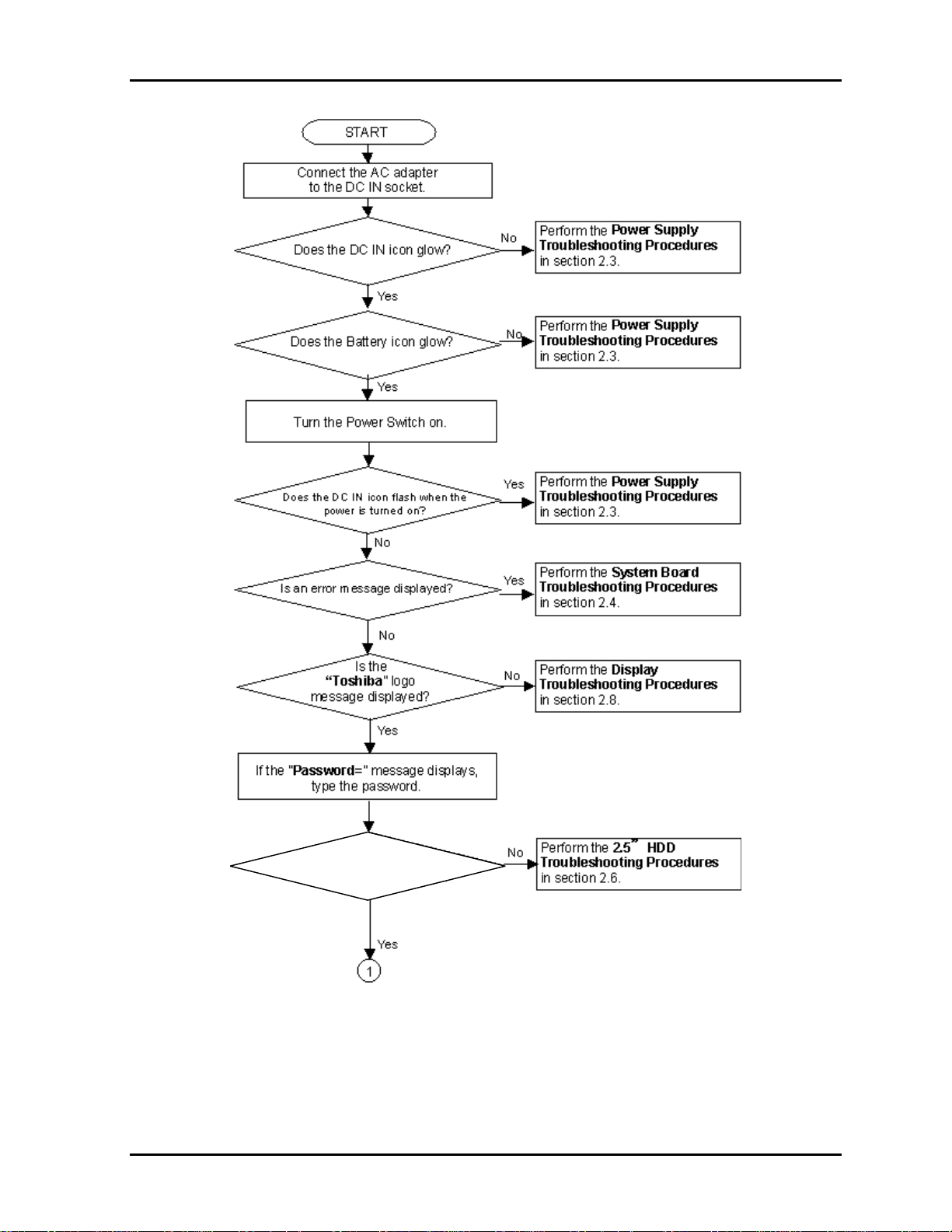
2.2 Troubleshooting Flowchart
Use the flowchart in Figure 2-1 as a guide for determining which FRU malfunctions. Before
going through the flowchart steps, check the following:
Make sure that Toshiba Windows
®
XP Tablet PC Edition is installed on the hard disk.
Non-Toshiba operating systems can cause the computer malfunction.
Make sure all optional equipment is removed from the computer.
Make sure the USB FDD is empty.
2-2 Portege M200 Maintenance Manual (960-457)
Page 9
2.2 Troubleshooting Flowchart 2 Troubleshooting
Is Toshiba Windows XP Tablet
Edition being loaded?
Figure 2-1 Troubleshooting flowchart (1/2)
Portege M200 Maintenance Manual (960-457) 2-3
Page 10
2 Troubleshooting Procedures 2.2 Troubleshooting Flowchart
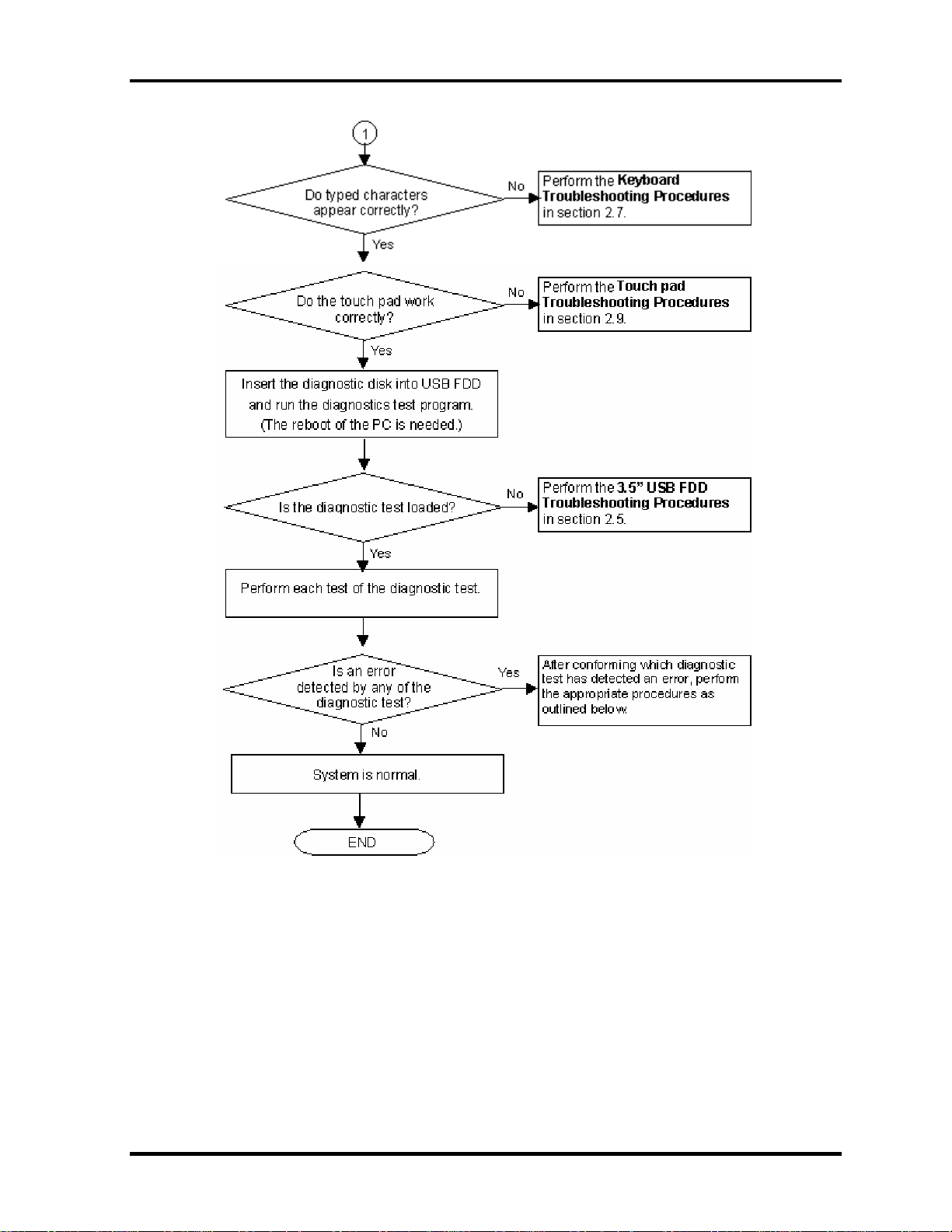
Figure 2-1 Troubleshooting flowchart (2/2)
2-4 Portege M200 Maintenance Manual (960-457)
Page 11

2.2 Troubleshooting Flowchart 2 Troubleshooting
If the diagnostics program cannot detect an error, the problem may be intermittent. The Test
program should be executed several times to isolate the problem. Check the Log Utilities
function to confirm which diagnostic test detected an error(s), then perform the appropriate
troubleshooting procedures as follows:
1. If an error is detected on the System test, Memory test, ASYNC test, Real timer test,
NDP test or expansion test, perform the System Board Troubleshooting Procedures in
Section 2.4.
2. If an error is detected on the Keyboard test, perform the Keyboard Troubleshooting
Procedures in Section 2.7.
3. If an error is detected on the Display test, perform the Display Troubleshooting
Procedures in Section 2.8.
4. If an error is detected on the Floppy disk test, perform the USB FDD Troubleshooting
Procedures in Section 2.5.
5. If an error is detected on the Hard disk test, perform the HDD Troubleshooting
Procedures in Section 2.6.
6. If an error is detected on the modem test, perform the Modem Troubleshooting
Procedures in Section 2.10.
7. If an error is detected on the LAN test, perform the LAN Troubleshooting Procedures
in Section 2.11.
8. If an error is detected on the sound test, perform the Sound Troubleshooting
Procedures in Section 2.12.
9. If an error is detected on the wireless LAN test, perform the Wireless LAN
Troubleshooting Procedures in Section 2.15.
Portege M200 Maintenance Manual (960-457) 2-5
Page 12

2 Troubleshooting Procedures 2.3 Power Supply Troubleshooting
2.3 Power Supply Troubleshooting
The power supply controller controls many functions and components. To determine if the
power supply is functioning properly, start with Procedure 1 and continue with the other
Procedures as instructed. The procedures described in this section are:
Procedure 1: Power Supply Icon Check
Procedure 2: Error Code Check
Procedure 3: Connection Check
Procedure 4: Quick Charge Check
Procedure 5: Replacement Check
2-6 Portege M200 Maintenance Manual (960-457)
Page 13
2.3 Power Supply Troubleshooting 2 Troubleshooting
Procedure 1 Power Supply Icon Check
The following two icons indicate the power supply status:
Battery icon
DC IN icon
The power supply controller uses the power supply status with the Battery icon and the DC IN
icon as listed in the tables below.
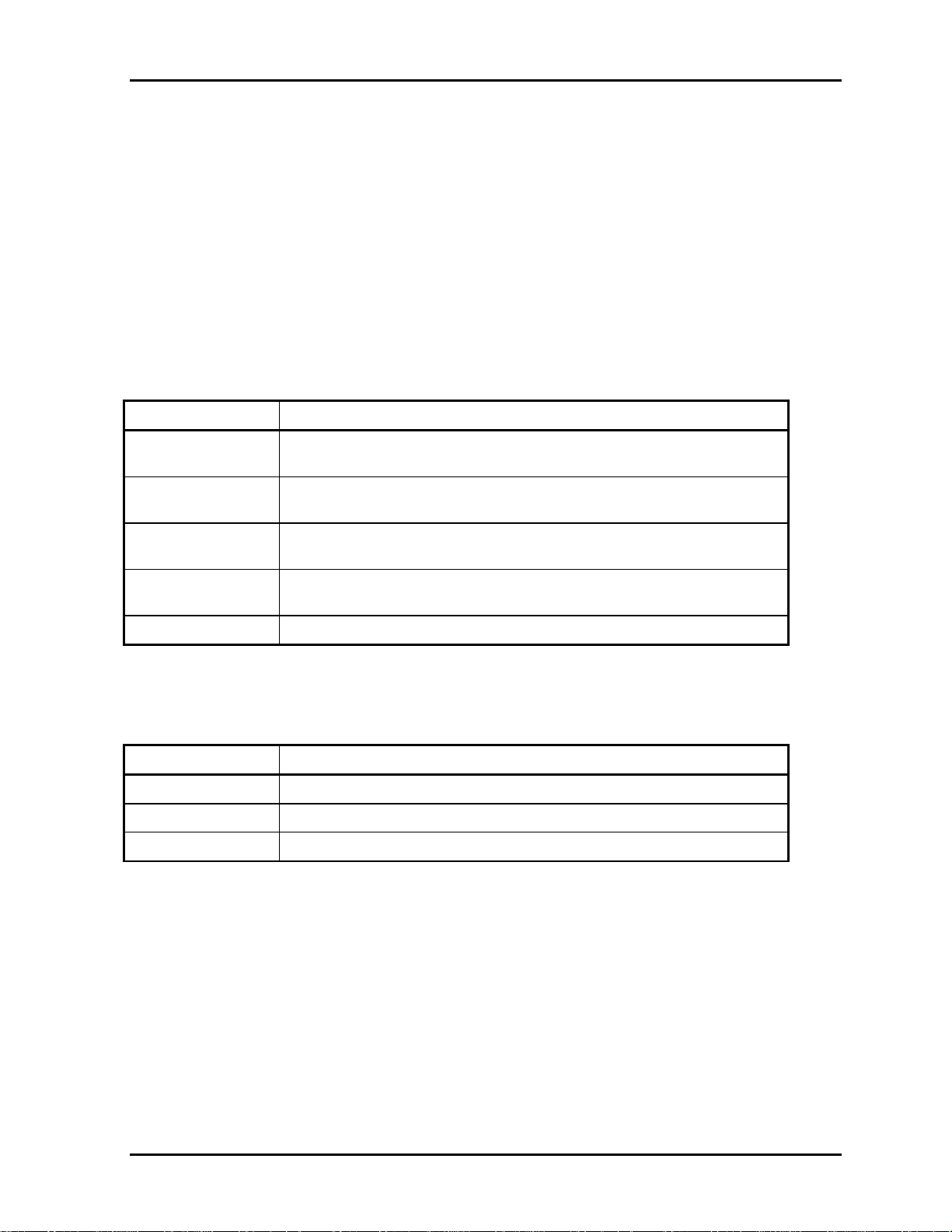
Table 2-1 Battery icon
Battery icon Power supply status
Lights orange Battery is charged and the external DC is input. It has no relation with
ON/OFF of the system power.
Lights green Battery is fully charged and the external DC is input. It has no relation
with ON/OFF of the system power.
Blinks orange
(even intervals)
Flashes orange The battery level is low and the power switch is pressed on in the
Doesn’t light Any condition other than those above.
The battery level is low while the system power is ON.
battery driving.
Table 2-2 DC IN icon
DC IN icon Power supply status
Lights green DC power is being supplied from the AC adapter.
Blinks orange Power supply malfunction
Doesn’t light Any condition other than those above.
* 1
*1 When the power supply controller detects a malfunction, the DC IN icon blinks
orange. It shows an error code.
Portege M200 Maintenance Manual (960-457) 2-7
Page 14
2 Troubleshooting Procedures 2.3 Power Supply Troubleshooting
When icons are blinking, perform the following procedure.
1. Remove the battery pack and the AC adapter and cut off the power supply to the
computer by force.
2. Re-attach the battery pack and the AC adapter.
If icons are still blinking after the operation above, check the followings:
Check 1 If the DC IN icon blinks orange, go to Procedure 2.
Check 2 If the DC IN icon does not light, go to Procedure 3.
Check 3 If the battery icon does not light orange or green, go to Procedure 4.
CAUTION: Use a recommended AC adapter (G71C0002S310).
2-8 Portege M200 Maintenance Manual (960-457)
Page 15
2.3 Power Supply Troubleshooting 2 Troubleshooting
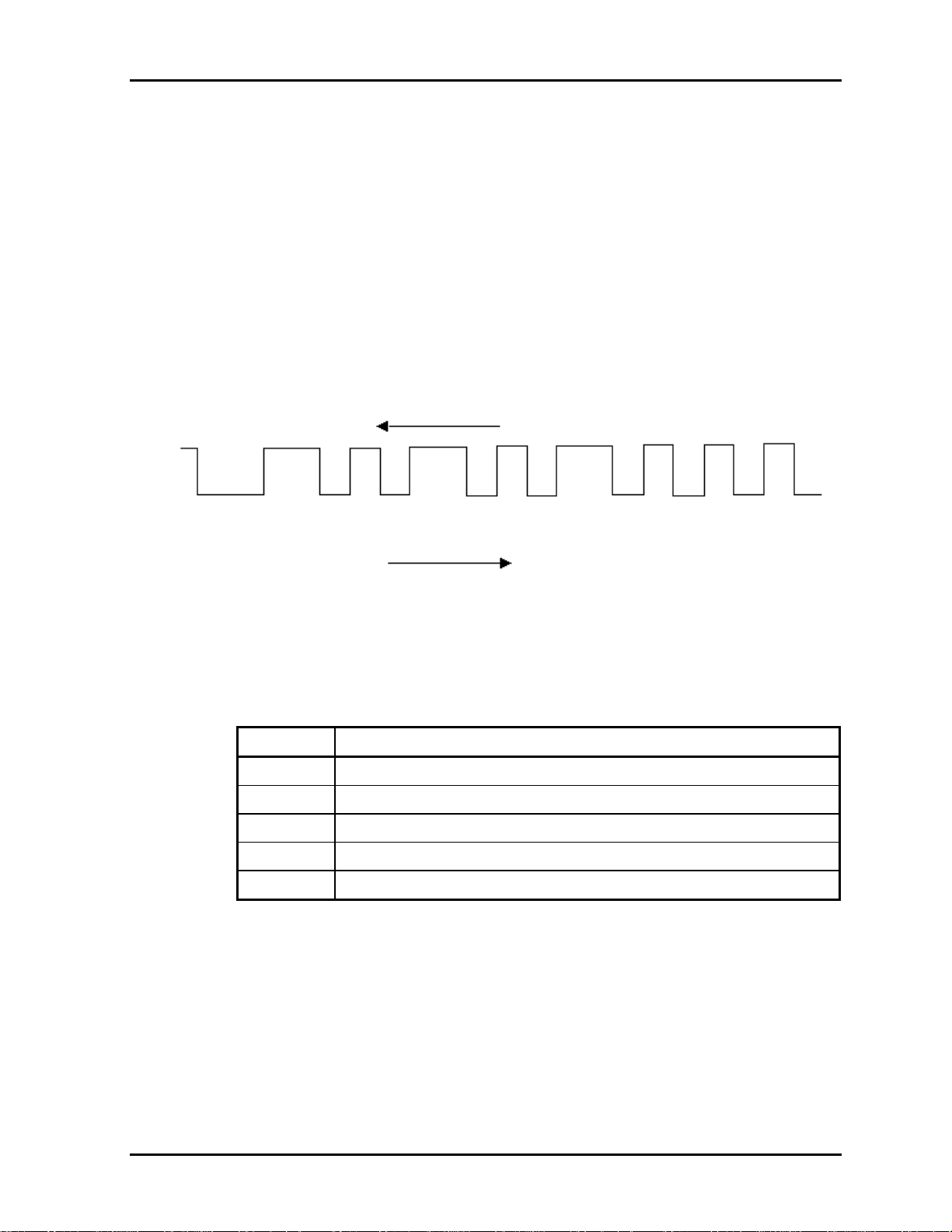
Procedure 2 Error Code Check
If the power supply microprocessor detects a malfunction, the DC IN icon blinks orange. The
blink pattern indicates an error as shown below.
Start Off for 2 seconds
Error code (8 bit)
“1” On for one second
“0” On for half second
Interval between data bits On for half second
The error code begins with LSB (Least Significant bit)
Example: Error code 11h (Error codes are given in hexadecimal format.)
Read
On
1
0
0
0
10
00
Off
Start
D0
D1 D2
Order
D3
D4
D5
D6
Check 1 Convert the DC IN icon blink pattern into the hexadecimal error code and
compare it to the tables below. Then go to Check 2.
DC power supply (AC adapter)
Error code Meaning
10h AC Adapter output voltage is over 16.5V.
11h Tablet multi dock output voltage is over 16.5V.
12h Current from the DC power supply is over 7.0A.
13h Current from the DC power supply is over 0.5A when there is no load.
14h Abnormal current has been sensed 0[A].
D7
Portege M200 Maintenance Manual (960-457) 2-9
Page 16
2 Troubleshooting Procedures 2.3 Power Supply Troubleshooting
Main Battery
Error code Meaning
20h Overvoltage is detected. (This is not supported.)
21h Main battery charge current is over 7.00A.
22h Main battery discharge current is over 0.5A when there is no load.
23h Main battery charge current is over 3.1A when AC adapter is not
connected.
24h Abnormal current has been sensed 0[A].
25h Main battery charge current is over 0.3A.
Second Battery
Error code Meaning
30h Overvoltage is detected. (This is not supported.)
S3V output (P60)
Error code Meaning
31h Second battery charge current is over 7.00A.
32h Second battery discharge current is over 0.5A when there is no load.
33h Second battery charge current is over 3.1A when AC adapter is not
connected.
34h Abnormal current has been sensed 0[A].
35h Second battery charge current is over 0.3A.
40h S3V voltage is 3.14V or less when the computer is powered on/off.
45h S3V voltage is 3.14V or less when the computer is booting up.
(CV support)
2-10 Portege M200 Maintenance Manual (960-457)
Page 17
2.3 Power Supply Troubleshooting 2 Troubleshooting
1R5-C1V output (P61)
Error code Meaning
50h 1R5-C1V voltage is over 1.80V when the computer is powered on/off.
51h 1R5-C1V voltage is 1.275V or less when the computer is powered on.
52h 1R5-C1V voltage is 1.275V or less when the computer is booting up.
53h 1R5-C1V voltage is 1.275V or less when the computer is suspended.
54h 1R5-C1V voltage is abnormal during shutdown (CV support)
55h 1R5-C1V voltage is 1.275V or less when the computer is booting up.
(CV support)
1R8-C1V output (P62)
Error code Meaning
60h 1R8-C1V voltage is over 2.16V when the computer is powered on/off.
61h 1R8-C1V voltage is 1.53V or less when the computer is powered on.
62h 1R8-C1V voltage is 1.53V or less when the computer is booting up.
63h 1R8-C1V voltage is 1.53V or less when the computer is suspended.
64h 1R8-C1V voltage is abnormal during shutdown (CV support)
65h 1R8-C1V voltage is 1.53V or less when the computer is booting up.
(CV support)
PPV output (P63 : MUX_CH0)
Error code Meaning
70h PPV voltage is over 1.80V when the computer is powered on/off.
71h PPV voltage is 0.56V or less when the computer is powered on.
72h PPV voltage is 0.56V or less when the computer is booting up.
73h PPV voltage is 0.56V or more when the computer is powered off.
Portege M200 Maintenance Manual (960-457) 2-11
Page 18
2 Troubleshooting Procedures 2.3 Power Supply Troubleshooting
PGV output (P64 : MUX_CH0)
Error code Meaning
80h PGV voltage is over 1.62V when the computer is powered on/off.
81h PGV voltage is 0.68V or less when the computer is powered on.
82h PGV voltage is 0.68V or less when the computer is booting up.
83h PGV voltage is 0.68V or more when the computer is powered off.
84h PGV voltage is 0.68V or less when the computer is suspended.
E5V output (P65 : MUX_CH0)
Error code Meaning
90h E5V voltage is over 6.00V when the computer is powered on/off.
91h E5V voltage is 4.50V or less when the computer is powered on.
92h E5V voltage is 4.50V or less when the computer is booting up.
93h E5V voltage is 4.50V or more when the computer is powered off.
94h E5V voltage is 4.50V or less while the computer is suspended.
E3V output (P66 : MUX_CH0)
Error code Meaning
A0h E3V voltage is over 3.96V when the computer is powered on/off.
A1h E3V voltage is 2.81V or less when the computer is powered on.
A2h E3V voltage is 2.81V or less when the computer is booting up.
A3h E3V voltage is 2.81V or more when the computer is powered off.
A4h E3V voltage is 2.81V or less while the computer is suspended.
1R2-P1V output (P63 : MUX_CH1)
Error code Meaning
B0h 1R2-P1V voltage is over 1.44V when the computer is powered on.
B1h 1R2-P1V voltage is 1.02V or less when the computer is powered on.
B2h 1R2-P1V voltage is 1.02V or less when the computer is booting up.
B3h 1R2-P1V voltage is 1.02V or more when the computer is powered off.
2-12 Portege M200 Maintenance Manual (960-457)
Page 19
2.3 Power Supply Troubleshooting 2 Troubleshooting
2R5-P2V output (P64 : MUX_CH1)
Error code Meaning
C0h 2R5-P2V voltage is over 3.00V when the computer is powered on.
C1h 2R5-P2V voltage is 2.125V or less when the computer is powered on.
C2h 2R5-P2V voltage is 2.125V or less when the computer is booting up.
C3h 2R5-P2V voltage is 2.125V or more when the computer is powered off.
C4h 2R5-P2V voltage is 2.125V or less while the computer is suspended.
1R25-P1V output (P65 : MUX_CH1)
Error code Meaning
D0h 1R25-P1V voltage is over 1.50V when the computer is powered on.
D1h 1R25-P1V voltage is 1.063V or less when the computer is powered on.
D2h 1R25-P1V voltage is 1.063V or less when the computer is booting up.
D3h 1R25-P1V voltage is 1.063V or more when the computer is powered
off.
D4h 1R25-P1V voltage is 1.063V or less while the computer is suspended.
2R5-B2V output (P66 : MUX_CH1)
Error code Meaning
E0h 2R5-B2V voltage is over 3.00V when the computer is powered on.
E1h 2R5-B2V voltage is 2.125V or less when the computer is powered on.
E2h 2R5-B2V voltage is 2.125V or less when the computer is booting up.
E3h 2R5-B2V voltage is 2.125V or more when the computer is powered off.
E4h 2R5-B2V voltage is 2.125V or less while the computer is suspended.
Check 2 In the case of error code 10h or 12h:
Make sure the AC adapter and AC power cord are firmly plugged into the DC
IN 15 V socket and wall outlet. If the cables are connected correctly, go to the
following step:
Connect a new AC adapter and AC power cord. If the error still exists, go to
Procedure 5.
Check 3 In the case of error code 21h:
Go to Procedure 3.
Portege M200 Maintenance Manual (960-457) 2-13
Page 20

2 Troubleshooting Procedures 2.3 Power Supply Troubleshooting
Check 4 For any other errors, go to Procedure 5.
2-14 Portege M200 Maintenance Manual (960-457)
Page 21

2.3 Power Supply Troubleshooting 2 Troubleshooting
Procedure 3 Connection Check
The wiring diagram related to the power supply is shown below:
Any of the connectors may be disconnected. Perform starting from Check 1.
Check 1 Make sure the AC adapter and the AC power cord are firmly plugged into the DC
IN 15 V socket and wall outlet. If these cables are connected correctly, go to Check
2.
Check 2 Replace the AC adapter and the AC power cord with new ones.
• If the DC IN icon does not light, go to Procedure 5.
• If the battery icon does not light, go to Check 3.
Check 3 Make sure the battery pack is installed in the computer correctly. If the battery is
properly installed and the battery icon still does not light, go to Procedure 4.
Procedure 4 Quick Charge Check
Check if the power supply controller charges the battery pack properly. Perform the following
procedures:
Check 1 Make sure the AC adapter is firmly plugged into the DC IN socket.
Check 2 Make sure the battery pack is properly installed. If the battery is properly installed,
go to Check 3.
Check 3 The battery pack may be completely discharged. Wait a few minutes to charge the
battery pack while connecting the battery pack and the AC adapter. If the battery
pack is still not charged, go to Check 4.
Check 4 The battery’s temperature is too high or low. Return the temperature to normal
operating condition. If the battery pack is still not charged, go to Check 5.
Check 5 Replace the battery pack with a new one. If the battery pack is still not charged, go
to Procedure 5.
Portege M200 Maintenance Manual (960-457) 2-15
Page 22

2 Troubleshooting Procedures 2.3 Power Supply Troubleshooting
Procedure 5 Replacement Check
The power is supplied to the system board by the AC adapter. If either the AC adapter or the
system board was damaged, perform the following Checks.
To disassemble the computer, follow the steps described in Chapter 4.
Check 1 Replace the AC adapter with a new one. If the AC adapter is still not functioning
properly, perform Check 2.
Check 2 Replace the system board with a new one.
2-16 Portege M200 Maintenance Manual (960-457)
Page 23

2.4 System Board Troubleshooting 2 Troubleshooting
2.4 System Board Troubleshooting
This section describes how to determine if the system board is defective. Start with Procedure
1 and continue with the other procedures as instructed. The procedures described in this
section are:
Procedure 1: Message Check
Procedure 2: Debug port (D port) Check on Boot Mode
Procedure 3: Diagnostic Test Program Execution Check
Procedure 4: Replacement Check
Portege M200 Maintenance Manual (960-457) 2-17
Page 24

2 Troubleshooting Procedures 2.4 System Board Troubleshooting
Procedure 1 Message Check
When the power is turned on, the system performs the Initial Reliability Test (IRT) installed
in the BIOS ROM. The IRT tests each IC on the system board and initializes it.
If an error message is shown on the display, perform Check 1.
If there is no error message, go to Procedure 2.
If MS-DOS or Windows XP Tablet PC Edition is properly loaded, go to Procedure 4.
Check 1 If one of the following error messages is displayed on the screen, press the F1 key
as the message instructs. These errors occur when the system configuration
preserved in the RTC memory (CMOS type memory) is not the same as the actual
configuration or when the data is lost.
If you press the F1 key as the message instructs, the SETUP screen appears to set
the system configuration. If any other error message is displayed, perform Check 2.
(a)*** Bad HDD type ***
Check system. Then press [F1] key ......
(b)*** Bad configuration ***
Check system. Then press [F1] key ......
(c)*** Bad memory size ***
Check system. Then press [F1] key ......
(d)*** Bad time function ***
Check system. Then press [F1] key ......
(e)*** Bad check sum (CMOS) ***
Check system. Then press [F1] key ......
(f)*** Bad check sum (ROM) ***
Check system. Then press [F1] key ......
(g)RTC battery is low or CMOS checksum is inconsistent
Press [F1] key to set Date/Time
Check 2 If the following error message is displayed on the screen press any key as the
message instructs.
The following error message appears when data stored in RAM under the resume
function is lost because the battery has become discharged or the system board is
damaged. Go to Procedure 3.
WARNING: RESUME FAILURE.
PRESS ANY KEY TO CONTINUE.
If any other error message is displayed, perform Check 3.
2-18 Portege M200 Maintenance Manual (960-457)
Page 25

2.4 System Board Troubleshooting 2 Troubleshooting
Check 3 The IRT checks the system board. When the IRT detects an error, the system stops
or an error message appears.
If one of the following error messages (1) through (17), (24) or (25) is displayed,
go to Procedure 5.
If error message (18) is displayed, go to the Keyboard Troubleshooting Procedures
in Section 2.7.
If error message (19), (20) or (21) is displayed, go to the 2.5” HDD
Troubleshooting Procedures in Section 2.6.
If error message (22) or (23) is displayed, go to the 3.5” USB FDD
Troubleshooting Procedures in Section 2.5.
(1) PIT ERROR
(2) MEMORY REFRESH ERROR
(3) TIMER CH.2 OUT ERROR
(4) CMOS CHECKSUM ERROR
(5) CMOS BAD BATTERY ERROR
(6) FIRST 64KB MEMORY ERROR
(7) FIRST 64KB MEMORY PARITY ERROR
(8) VRAM ERROR
(9) SYSTEM MEMORY ERROR
(10) SYSTEM MEMORY PARITY ERROR
(11) EXTENDED MEMORY ERROR
(12) EXTENDED MEMORY PARITY ERROR
(13) DMA PAGE REGISTER ERROR
(14) DMAC #1 ERROR
(15) DMAC #2 ERROR
(16) PIC #1 ERROR
(17) PIC #2 ERROR
(18) KBC ERROR
(19) HDC ERROR
(20) HDD #0 ERROR
(21) HDD #1 ERROR
(22) NO FDD ERROR
(23) FDC ERROR
(24) TIMER INTERRUPT ERROR
(25) RTC UPDATE ERROR
Portege M200 Maintenance Manual (960-457) 2-19
Page 26

2 Troubleshooting Procedures 2.4 System Board Troubleshooting
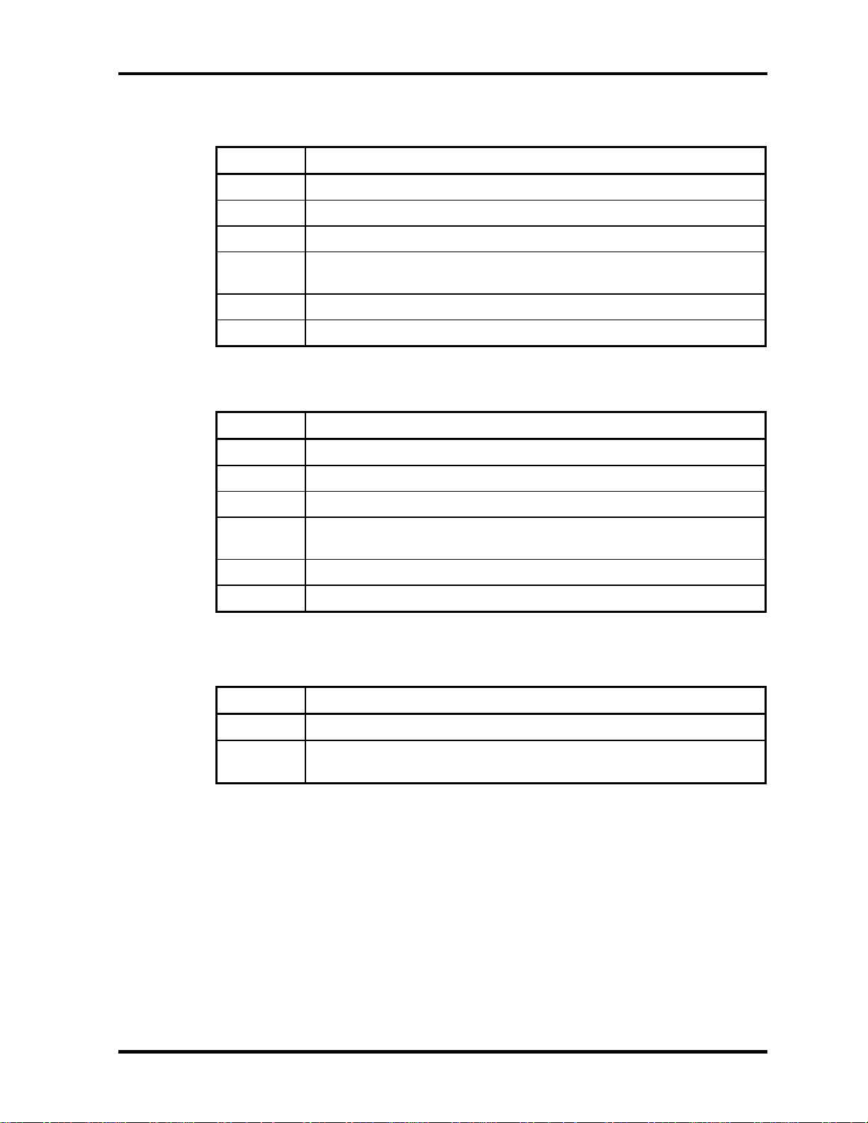
Procedure 2 Debug Port (D port) Check on Boot Mode
Check the D port status by a debug port test. The tool for debug port test is shown below.
Figure 2-2 A tool set for debug port test
The test procedures are follows;
1. Connect the debug test cable to the connector PJ2000 of the system board. For
disassembling to connect the test cable, refer to Chapter 4.
2. Connect the debug port test cable and RS-232C cross-cable to the test board.
3. Connect the RS-232C cross-cable to the PC that displays the results.
PJ2000
4. Boot the computer in MS-DOS mode.
2-20 Portege M200 Maintenance Manual (960-457)
Page 27

2.4 System Board Troubleshooting 2 Troubleshooting
5. Execute GETDPORT.COM in the text menu in CPU REAL mode. (Insert the FD for
starting D port into FDD and input “FD starting drive:>dport”.)
The D port status is displayed in the following form;
6. When the D port status is FFFFh (normal status), go to Procedure 3.
7. When the D port status falls into any status in Table 2-3, execute Check 1.
Portege M200 Maintenance Manual (960-457) 2-21
Page 28

2 Troubleshooting Procedures 2.4 System Board Troubleshooting
Table 2-3 D port status (1/7)
D port
status
F000h
F001h Checking if EC/KBC firmware is to be rewritten Shifting to BIOS rewriting process if
Executing KBC initializing sequence
Sending KBC enable command
Checking F12 key-in
F002h Initializing security controller
F003h to
F005h
F006H Checking BIOS signature
F007h Shifting process to System BIOS IRT side For BIOS rewriting process
BIOS rewriting process
F008h Changing ROM BIOS to RAM BIOS
F009h
Clearing software reset bit
Enabling address line A20
Initializing special registers and M1535
Initializing the CH0 of a PIT (for HOLD_ON)
Initializing flag for BIOS rewriting factor
CHECK SUM CHECK (FEFC0000h to FEFF7FFFh)
Shifting to protected mode
Examining the checksum of Boot Block HALT when checksum is not correct.
Examining the checksum of data except Boot Block
Checking whether BIOS rewrite is requested Checksum error except Boot Block or
Initializing unique HW for this model
Initializing GPIO I/O space
Enabling BIOS writing
Serial interrupt control
Canceling BIOS write protection
Enabling SMBus I/O space
Enabling SMBus access
Configuring DRAM
Enabling L1 cache memory
Clearing memory
Storing key scan codes
Setting up TASK_1ms_TSC
Displaying message on navipanel (EC/KBC UPDATE,
BIOS UPDATE/DAMAGED)
Details
Remarks
BIOS rewriting request exists
rewriting request by F12key-in
2-22 Portege M200 Maintenance Manual (960-457)
Page 29

2.4 System Board Troubleshooting 2 Troubleshooting
Table 2-3 D port status (2/7)
D port
status
F009h
Details Remarks
Key inputting
Loading CHGBIOSA.EXE and
CHGFIRMA.EXE
Resetting FDC
Setting parameter for 2HD (1.44MB) and
transmission rate
Reading the first sector When it is sector for 2HD, media
Setting parameter for 2DD (720KB)and
transmission rate
Searching CHGBIOSA.EXE in the root
directory
Calculating start head and sector of directory
Reading contents of root directory by one
sector
Searching entry of “CHGBIOSA.EXE”/
“CHGFIRMA.EXE” in the sector
type is determined.
Reading EXE header of “CHGBIOSA.EXE”/
“CHGFIRMA.EXE”
Executing CHGBIOSA.EXE and
CHGFIRMA.EXE
F100h Disabling cache
Initializing special registers
Initializing Ch1 of a PIT
(Refresh interval ->30 micro seconds)
F101h
Checking size and type of DRAM (on Cold
Booting)
Checking DRAM size HALT when DRAM size is 0.
Testing stack area of SMRAM HALT when it can be used as
If error occurs, process goes to
key input.
stack area.
Portege M200 Maintenance Manual (960-457) 2-23
Page 30

2 Troubleshooting Procedures 2.4 System Board Troubleshooting
Table 2-3 D port status (3/7)
D port
status
F102h
F103h
Details Remarks
Configuring cache memory
Enabling L1 cache memory
Testing CMOS for access (on Cold Booting)
Checking remaining of CMOS backup battery
Examining checksum of CMOS
Initializing data in CMOS (1)
Setting up IRT status (Set "1" for Boot status
and IRT busy flag bit. Set "0" for other bits.)
Storing size of DRAM
Checking for branch of resuming (only on
Cold Boot)
No resume
1. when CMOS error occurs.
2. when Resume Status Code is
not set.
Checking resume error
ICH4-M Power Failure Resume error 7Ah
Examining the checksum of SMRAM Resume error 73h
Checking whether the memory
Resume error 73h
configuration have been changed
Examining the checksum of system BIOS
Resume error 79h
RAM area
Shifting to resuming process
(RESUME_MAIN)
Resume error process
Disabling all SMIs
Clearing resuming status
Returning to ROM
Setting up area from C0000h to EFFFFh for PCI
(disabling DRAM)
Setting a request for resuming error
Copying system BIOS from ROM to RAM
HALT when error occurs.
2-24 Portege M200 Maintenance Manual (960-457)
Page 31

2.4 System Board Troubleshooting 2 Troubleshooting
Table 2-3 D port status (4/7)
D port
status
F104h
F106h
Details Remarks
Initializing SMRAM
Checking factor of WakeUp
Rewriting SMRAM base and storing CPU state
map for BIOS
Enabling SMI by ASMI
Initializing devices which need initialization before
initializing PCI bus
Testing (only on COLD booting) and Initializing PIT
Setting test pattern to channel 0 of PIT#0
Checking whether the test pattern can be read
Initializing PIT channel 0 (Interval of timer interrupt
-> 55ms)
Initializing PIT channel 2 (frequency for sound
generator -> 664Hz)
Testing PIT channel 1(checks whether the refresh
signal operates correctly in refresh interval of 30
micro seconds)
Testing PIT channel 2 ( checks whether the
speaker gate operates correctly)
Measuring CPU clock
HALT when time out occurs.
Enabling SMIs except auto-off function
Control of battery discharging current
Performing timeshared process for time
measurement of IRT
Initializing CPU
Updating P6 micro-code
Enabling or disabling function of processor
serial number ID
Checking whether Geyserville is supported
Switching CPU clock speed to high
Setting Graphics Aperture Size
Portege M200 Maintenance Manual (960-457) 2-25
Page 32

2 Troubleshooting Procedures 2.4 System Board Troubleshooting
Table 2-3 D port status (5/7)
D port
status
F107h
F108h
F10Ch
F10Dh
Details Remarks
Storing memory size of ROM in buffer
Reading EC version
Updating the type of flash ROM
Determining the destination based on DMI data
Checking default setting of CMOS
Set to default value to CMOS if
Bad Battery or Bad Checksum
(ROM, CMOS) exists.
Initializing ACPI table (for optional ROM)
Storing results of VGA configuration
Generating task waiting for completion of
PCI_CONFIGURATION
Initializing H/W needed after PCI configuration
Enabling/Disabling IEEE1394
Generating output codes
FIRST_64KB_CHECK (Checking first 64KB of
memory)
INIT_INT_VECTOR (Initializing interrupt vectors)
F10Eh
F10Fh
F110h
F111h
F112h
F113h
F114h
INT_NDP (Initializing NDP)
INIT_SYSTEM (Initializing system)
Storing CMOS error information in
IRT_ERR_STS_BUF
Initializing timer
Initializing buffer for power saving
Initializing an EC, and reading battery information
Updating system BIOS (model name, and EDID of
the LCD)
INIT_DISPLAY (Waiting for completion of
initializing VGA chip and pre-processing for
initializing VGA BIOS)
Initializing VGA BIOS
Post-processing for Initializing VGA BIOS
DISP_LOGO (Displaying logo)
SYS_MEM_CHECK (Checking conventional
memory)
2-26 Portege M200 Maintenance Manual (960-457)
Page 33

2.4 System Board Troubleshooting 2 Troubleshooting
Table 2-3 D port status (6/7)
D port
status
F115h
F116h
F117h
F11Ah
F11Bh
F11Eh
F11Fh
Details Remarks
EXT_MEM_CHECK (Checking exception in
protect mode)
CHK_DMA_PAGE (Checking DMA Page Register)
CHECK_DMA (Checking DMAC)
INT_DMAC (Initializing DMAC)
BOOT_PASSWORD (Checking password)
Waiting for end of divided FDD initialization
(INT_FDD) process
Waiting for the end of HDD initialization
Checking key input pressed during IRT Waiting for completion of KBC
Initializing ATA prioritizing
EX_IO_ROM_CHECK (Checking optional I/O
ROM)
PRE_BOOT_SETUP
Storing value of 40:00 (for saving/restoring SIO)
Setting up address of font data for resume
password
Setting up parameters for character repeat on
USB keyboard
Getting keys pressed during IRT
initializing
Storing T_SHADOW_RAM_SIZE (shadow RAM
size)
Updating system resources information prior to
boot-up
Rewriting memory mapping data for INT15h
E820h function
Updating table for DMI
Copying ACPI table to top of expansion
memory
Waiting for completion of writing PSC version
on BIOS
Waiting for completion of setting for clock
generator
If error occurs, process stops with
D port = 1Eh.
Portege M200 Maintenance Manual (960-457) 2-27
Page 34

2 Troubleshooting Procedures 2.4 System Board Troubleshooting
Table 2-3 D port status (7/7)
D port
status
(F11Fh)
Details Remarks
Canceling NMI mask
Calculating checksum of TIT
Clearing IRT running flag for runtime
Update checksum for runtime
Checking whether CPU, HDD or other components
have been upgraded
Disabling PC Card not being used
Initializing HW prior to BOOT, Waiting for
completion of initializing
Setting up battery save mode
Setting up date
Waiting for completion of AC-Link initialization
Updating DMI Wakeup factor and SM-BIOS
structure table
Closing configuration space of PCI devices
Cache control
F121h
FFFFh
Processing related to CPU
Updating parameter block A
Setting up CPU clock speed to designated value
by Setup
Waiting for motor off of disabled HDD
Post processing of PRE_BOOT_SETUP
Clearing power button status (PWRBTN)
Enabling power button
Checking request for starting SETUP (by pressing
ESC key or CMOS error)
SETUP starts if any request exists.
2-28 Portege M200 Maintenance Manual (960-457)
Page 35

2.4 System Board Troubleshooting 2 Troubleshooting
Check 1 If the D port status error code F119h is displayed, go to the 3.5” USB FDD
Troubleshooting Procedures in Section 2.5 or the 2.5” HDD Troubleshooting
Procedures in Section 2.6.
Check 2 If any other D port status error code is displayed, perform Procedure 3.
D port error status is as follows:
Error code Contents
F160h Timer CH2 error
F161h PIT error
F162h PIC #1 error
F163h PIC #2 error
F120h Clock generator setting error
Portege M200 Maintenance Manual (960-457) 2-29
Page 36

2 Troubleshooting Procedures 2.4 System Board Troubleshooting
Procedure 3 Diagnostic Test Program Execution Check
Execute the following tests from the Diagnostic Test Menu. These tests check the system
board. Refer to Chapter 3, Tests and Diagnostic, for more information on how to perform
these tests.
1. System test
2. Memory test
3. Keyboard test
4. Display test
5. USB Floppy Disk test
6. ASYNC test
7. Hard Disk test
8. Real Timer test
9. NDP test
10. Expansion test
11. Wireless LAN test
12. Bluetooth test
13. Sound/LAN/Modem test
If an error is detected during these tests, go to Procedure 4.
Procedure 4 Replacement Check
The system board connectors may be disconnected. Disassemble the computer following the
steps described in Chapter 4, Replacement Procedures and perform Check 1.
Check 1 Visually check for the following:
a) Cracked or broken connector housing
b) Damaged connector pins
If connectors are in good condition, but there is still a problem, go to Check 2.
Check 2 The system board may be damaged. Replace the system board with a new one
following the steps described in Chapter 4, Replacement Procedures.
2-30 Portege M200 Maintenance Manual (960-457)
Page 37

2.5 USB 3.5” FDD Troubleshooting 2 Troubleshooting
2
2.5 USB 3.5” FDD Troubleshooting
This section describes how to determine if the USB 3.5” FDD is functioning properly.
Perform the steps below starting with Procedure 1 and continuing with the other procedures as
required.
Procedure 1: FDD Head Cleaning Check
Procedure 2: Diagnostic Test Program Execution Check
Procedure 3: Connector Check and Replacement Check
Procedure 1 FDD Head Cleaning Check
FDD head cleaning is one option available in the Diagnostic Program.
Insert the Diagnostics Disk in the USB floppy disk drive, turn on the computer and run the test.
And then clean the FDD heads using the cleaning kit. If the FDD still does not function
properly after cleaning, go to Procedure 2.
Detailed operation is given in Chapter 3, Tests and Diagnostics.
If the test program cannot be executed on the computer, go to Procedure 3.
Portege M200 Maintenance Manual (960-457) 2-31
Page 38

2 Troubleshooting Procedures 2.5 USB 3.5” FDD Troubleshooting
Procedure 2 Diagnostic Test Program Execution Check
Insert the Diagnostics Disk in the USB FDD, turn on the computer and run the test. Refer to
Chapter 3, Tests and Diagnostics, for more information about the diagnostics test procedures.
Make sure the floppy disk is formatted correctly and that the write protect tab is disabled.
Floppy disk drive test error codes and their status names are listed in Table 2-4. If any other
errors occur while executing the FDD diagnostics test, go to Check 1.
Table 2-4 FDD error code and status
Code Status
01h Bad command
02h Address mark not found
03h Write protected
04h Record not found
06h Media replaced
08h DMA overrun error
09h DMA boundary error
10h CRC error
20h FDC error
40h Seek error
60h FDD not drive
80h Time out error (Not ready)
EEh Write buffer error
FFh Data compare error
Check 1 If the following message is displayed, disable the write protect tab on the floppy
disk by sliding the write protect tab to “write enable”. If any other message appears,
perform Check 2.
Write protected
Check 2 Make sure the floppy disk is formatted correctly. If it is, go to Procedure 3.
2-32 Portege M200 Maintenance Manual (960-457)
Page 39

2.5 USB 3.5” FDD Troubleshooting 2 Troubleshooting
Procedure 3 Connector Check and Replacement Check
The USB FDD connector may be disconnected from the connector on the system board.
Check visually that the connector is connected firmly.
Check 1 Make sure the USB FDD cable is firmly connected to the PJ4600 or PJ4601 of the
system board.
System board
USB FDD
PJ4600 or PJ4601
If any of the connections are loose, reconnect firmly and repeat Procedure 2. If
there is still an error, go to Check 2.
Check 2 The USB FDD may be defective or damaged. Replace it with a new one. If the
FDD is still not functioning properly, perform Check 3.
Check 3 Replace the system board with a new one following the steps in Chapter 4,
Replacement Procedures.
Portege M200 Maintenance Manual (960-457) 2-33
Page 40

2 Troubleshooting Procedures 2.6 2.5” HDD Troubleshooting
2.6 2.5” HDD Troubleshooting
This section describes how to determine if the 2.5” HDD is functioning properly. Perform the
steps below starting with Procedure 1 and continuing with the other procedures as required.
Procedure 1: Partition Check
Procedure 2: Message Check
Procedure 3: Format Check
Procedure 4: Diagnostic Test Program Execution Check
Procedure 5: Connector Check and Replacement Check
CAUTION: The contents of the 2.5” hard disk will be erased when the 2.5” HDD
troubleshooting procedures are executed. Transfer the contents of the hard disk to floppy
disks or other storage drive(s). For the backup, refer to the User’s Manual.
Procedure 1 Partition Check
Insert the Toshiba MS-DOS system disk and start the computer. Perform the following
checks:
Check 1 Type C: and press Enter. If you cannot change to drive C, go to Check 2. If you
can change to drive C, go to Procedure 2.
Check 2 Type FDISK and press Enter. Choose Display Partition Information from the
FDISK menu. If drive C is listed in the Display Partition Information, go to Check
3. If drive C is not listed, return to the FDISK menu and choose the option to
create a DOS partition or a logical DOS drive on drive C. If the problem still exists,
go to Procedure 2.
Check 3 If drive C is listed as active in the FDISK menu, go to Check 4. If drive C is not
listed as active, return to the FDISK menu and choose the option to set the active
partition for drive C. Then go to Procedure 2.
Check 4 Remove the system disk from the FDD and reboot the computer. If the problem
still exists, go to Procedure 2. Otherwise, the HDD is operating normally.
2-34 Portege M200 Maintenance Manual (960-457)
Page 41

2.6 2.5” HDD Troubleshooting 2 Troubleshooting
Procedure 2 Message Check
When the power is turned on, the system performs the Initial Reliability Test (IRT) installed
in the BIOS ROM. When the test detects an error, an error message is displayed on the screen.
Make sure of no floppy disk in the FDD. Turn on the computer and check the message on the
screen. When an OS starts from the 2.5” HDD, go to Procedure 3. Otherwise, start with Check
1 below and perform the other checks as instructed.
Check 1 If any of the following messages appear, go to Procedure 3. If the following
messages do not appear, perform Check 2.
HDC ERROR
or
HDD #X ERROR (After 5 seconds this message will disappear.)
Check 2 If either of the following messages appears, go to Check 3. If the following
messages do not appear, perform Check 5.
Insert system disk in drive
Press any key when ready .....
or
Non-System disk or disk error
Replace and press any key when ready
Check 3 Check SETUP to see whether the Hard Disk option is set to Not used. If it is set to
Not used, choose another setting and return to Check 1. If it is not set to Not used,
go to Check 4.
Check 4 Using the SYS command of the MS-DOS, transfer the system to the 2.5" HDD. If
the system is not transferred, go to Procedure 3. Refer to the MS-DOS Manual for
detailed operation.
If the following message appears on the display, the system program has been
transferred to the HDD.
System Transferred
If an error message appears on the display, perform Check 5.
Check 5 The 2.5" HDD and the connector of the system board may be disconnected (Refer
to the steps described in Chapter 4, Replacement Procedures for disassembling.).
Insert the connectors firmly. If they are firmly connected, go to Procedure 3.
Portege M200 Maintenance Manual (960-457) 2-35
Page 42

2 Troubleshooting Procedures 2.6 2.5” HDD Troubleshooting
Procedure 3 Format Check
The computer’s 2.5" HDD is formatted using the MS-DOS FORMAT program or the physical
format program of the test program. To format the 2.5" HDD, start with Check 1 below and
perform the other steps as required.
Refer to the MS-DOS Manual for the operation of MS-DOS. For the format by the test
program, refer to the Chapter 3.
Check 1 Format the 2.5" HDD using MS-DOS FORMAT command. Type as FORMAT
C:/S/U.
If the 2.5" HDD can not be formatted, perform Check 2.
Check 2 Using the MS-DOS FDISK command, set the 2.5" HDD partition. If the partition
is not set, go to Check 3. If it is set, format the 2.5" HDD using MS-DOS
FORMAT command.
Check 3 Using the Diagnostic Disk, format the 2.5" HDD with a format option (physical
format). If the 2.5" HDD is formatted, set the 2.5" HDD partition using MS-DOS
FDISK command.
If you cannot format the 2.5" HDD using the Tests and Diagnostic program, go to
Procedure 4.
2-36 Portege M200 Maintenance Manual (960-457)
Page 43

2.6 2.5” HDD Troubleshooting 2 Troubleshooting
Procedure 4 Diagnostic Test Program Execution Check
The HDD test program is stored in the Diagnostics Disk. Perform all of the HDD tests in the
Hard Disk Drive Test. Refer to Chapter 3, Tests and Diagnostics, for more information about
the HDD test program.
If an error is detected during the HDD test, an error code and status will be displayed. The
error codes and statuses are described in Table 2-5. If an error code is not displayed but the
problem still exists, go to Procedure 5.
Table 2-5 2.5” HDD error code and status
Code Status
01h Bad command
02h Address mark not found
04h Record not found
05h HDC not reset
07h Drive not initialized
08h HDC overrun error (DRQ)
09h DMA boundary error
0Ah Bad sector error
0Bh Bad track error
10h ECC error
11h ECC recover enable
20h HDC error
40h Seek error
80h Time out error
AAh Drive not ready
BBh Undefined error
CCh Write fault
E0h Status error
EEh Access time out error
DAh No HDD
Portege M200 Maintenance Manual (960-457) 2-37
Page 44

2 Troubleshooting Procedures 2.6 2.5” HDD Troubleshooting
Procedure 5 Connector Check and Replacement Check
The HDD is connected to the connector PJ1800 of the system board. The connecting portion
may be disconnected. Disassemble the computer following the steps described in Chapter 4,
Replacement Procedures and perform the following checks to check the connecting portion:
Check 1 Make sure the HDD is firmly connected to the system board.
HDD
PJ1800
If connection is loose, reconnect firmly and repeat Procedure 4. If there is still an
error, go to Check 2.
Check 2 The 2.5" HDD may be damaged. Replace it with a new one and check the
operation. If the problem still exists, perform Check 3.
Check 3 The system board may be damaged. Replace it with a new one following the
instructions in Chapter 4, Replacement Procedures.
2-38 Portege M200 Maintenance Manual (960-457)
Page 45

2.7 Keyboard Troubleshooting 2 Troubleshooting
2.7 Keyboard Troubleshooting
To determine if the computer’s keyboard is functioning properly, perform the following
procedures. Start with Procedure 1 and continue with the other procedures as instructed.
Procedure 1: Diagnostic Test Program Execution Check
Procedure 2: Connector Check and Replacement Check
Procedure 1 Diagnostic Test Program Execution Check
Execute the Keyboard Test in the Diagnostic Program. Refer to Chapter 3, Tests and
Diagnostics for more information on how to perform the test program.
If an error occurs, go to Procedure 2. If an error does not occur, the keyboard is functioning
properly.
Procedure 2 Connector Check and Replacement Check
The keyboard or system board may be disconnected or damaged. Disassemble the computer
following the steps described in Chapter 4, Replacement Procedures and perform the
following checks:
Check 1 Make sure the keyboard cable is firmly connected to the system board.
Keyboard
PJ3230
If the connection is loose, reconnect firmly and repeat Procedure 1. If there is still
an error, go to Check 2.
Check 2 The keyboard may be damaged. Replace it with a new one following the
instructions in Chapter 4, Replacement Procedures. If the problem still exists,
perform Check 3.
Check 3 The system board may be damaged. Replace it with a new one following the
instructions in Chapter 4, Replacement Procedures.
Portege M200 Maintenance Manual (960-457) 2-39
Page 46

2 Troubleshooting Procedures 2.8 Display Troubleshooting
2.8 Display Troubleshooting
This section describes how to determine if the computer’s display is functioning properly.
Start with Procedure 1 and continue with the other procedures as instructed.
Procedure 1: Diagnostic Test Program Execution Check
Procedure 2: Connector and Cable Check
Procedure 3: Fuse Conduction Check
Procedure 4: Replacement Check
Procedure 1 Diagnostic Test Program Execution Check
The Display Test program is stored on the Diagnostics disk. Insert the Diagnostics disk in the
computer’s floppy disk drive, turn on the computer and run the test. Refer to Chapter 3, Tests
and Diagnostics for details.
This program checks the display controller on the system board. If an error is detected, go to
Procedure 3.
Procedure 2 Connector and Cable Check
The LCD module is connected to the system board through the LCD harness. The cable may
be disconnected from each board or damaged. Disassemble the computer following the steps
described in Chapter 4, Replacement Procedures. If the connection is loose, reconnect firmly
and repeat Procedure 2. If there is still an error, go to Procedure 3.
Procedure 3 Fuse Conduction check
Some fuses may be blown. To test the conduction of the fuse F2, F5000 and F5001 near the
LCD I/F connector (PJ5205, PJ5206), disassemble the computer following the steps described
in Chapter 4, Replacement Procedures. If either fuse is blown, replace the system board repeat
Procedure 3. If there is still an error, go to Procedure 4.
2-40 Portege M200 Maintenance Manual (960-457)
Page 47

2.8 Display Troubleshooting 2 Troubleshooting
Procedure 4 Replacement Check
The display unit has a FL inverter board, Display module, System board, LCD harness and
Display ON/OFF switch. Any of the components may be damaged. Disassemble the computer
following the steps described in Chapter 4, Replacement Procedures, then perform the
following checks:
(1) If characters or graphics are not displayed on the internal display, perform Check 1.
(2) If characters are displayed on the internal display but the display is not normal,
perform Check 2.
(3) If characters are displayed on the internal display but the display is dark (the back-light
does not light), perform Check 5.
Check 1 The display ON/OFF switch may be damaged. Remove the display ON/OFF
switch and repeat Procedure 4. If there is still an error, go to Check 2.
Check 2 The LCD harness may be damaged. Replace the damaged harness with a new one
and repeat Procedure 4. If there is still an error, go to Check 3.
Check 3 The display module may be damaged. Replace it with a new one and repeat
Procedure 4. If there is still an error, go to Check 4.
Check 4 The FL inverter board may be damaged. Replace it with a new one and repeat
Procedure 4. If there is still an error, go to Check 5.
Check 5 The FL tube may be damaged. Replace it with a new one and repeat Procedure 4.
If there is still an error, go to Check 6.
Check 6 The display controller of the system board may be damaged. Replace the system
board with a new one.
Portege M200 Maintenance Manual (960-457) 2-41
Page 48

2 Troubleshooting Procedures 2.9 Touch Pad Troubleshooting
2.9 Touch Pad Troubleshooting
To determine whether the Touch Pad is faulty or not, perform the following procedures:
Procedure 1: Diagnostic Test Program Execution Check
Procedure 2: Connector Check and Replacement Check
Procedure 3: Replacement Check
Procedure 1 Diagnostic Test Program Execution Check
Execute the keyboard test program, or maintenance test program, because the pointing device
(touch pad) test program is a component of the keyboard test program. For the operating
procedure, see Chapter 3.
If any error is detected, perform Procedure 2. The pointing device is operating normally if no
error is detected.
Procedure 2 Connector Check and Replacement Check
The touch pad is connected to the system board (PJ3240) with a flexible cable. This cable may
have come off the connector or the connector may have come off the system board.
Disassemble the computer and check the cable connections. See Chapter 4 for the disassembly
procedure. If the connector has come off, connect firmly and make sure the operation. If there
is still an error, go to Procedure 3.
Touch Pad
PJ3240
Procedure 3 Replacement Check
The touch pad may be damaged. Replace the touch pad.
2-42 Portege M200 Maintenance Manual (960-457)
Page 49

2.10 Modem Troubleshooting 2 Troubleshooting
2.10 Modem Troubleshooting
To check if the modem is defective or malfunctioning, follow the troubleshooting procedures
below as instructed.
Procedure 1: Diagnostic Test Program Execution Check
Procedure 2: Connector Check and Replacement Check
Procedure 1 Diagnostic Test Program Execution Check
Execute the Modem test program available as part of the maintenance test program. This
program checks the modem. See Chapter 3 for information on how to perform the test.
If any error is detected by the test, go to Procedure 2.
Procedure 2 Connector Check and Replacement Check
The Modem jack (RJ11) is mounted on the system board and MDC is connected to the system
board. If the modem malfunctions, the connection may be bad or the MDC or system board
might be faulty.
Disassemble the computer following the steps described in Chapter 4 and perform the
following checks:
Check 1 Make sure the MDC is firmly connected to the PJ3020 and the MDC cable is
connected to the PJ3021 on the system board.
System board
PJ3020
PJ3021
MDC
PJ4100
RJ11
If any connector is disconnected, connect it firmly and return to Procedure 1. If
there is still an error, perform Check 2.
Check 2 The MDC may be faulty. Replace it with a new one following the steps in Chapter
4. If the modem is not still working properly, perform Check 3.
Check 3 The system board may be faulty. Replace it with a new one following the
instructions in Chapter 4.
Portege M200 Maintenance Manual (960-457) 2-43
Page 50

2 Troubleshooting Procedures 2.11 LAN Troubleshooting
2.11 LAN Troubleshooting
To check if the computer’s LAN is defective or malfunctioning, follow the troubleshooting
procedures below as instructed.
Procedure 1: Diagnostic Test Program Execution Check
Procedure 2: Connector Check and Replacement Check
Procedure 1 Diagnostic Test Program Execution Check
To check the LAN function, execute the Sound/LAN/modem test program subtest 04 (LAN
test). See Chapter 3 for information on how to perform the test.
If any error is detected by the test, go to Procedure 2.
Procedure 2 Connector Check and Replacement Check
The LAN function is installed on the system board. The RJ45 jack is mounted on the system
board. If the LAN malfunctions, the system board might be faulty.
Disassemble the computer following the steps described in Chapter 4 and replace the system
board.
RJ45 jack
PJ4100
2-44 Portege M200 Maintenance Manual (960-457)
Page 51

2.12 Sound Troubleshooting 2 Troubleshooting
2.12 Sound Troubleshooting
To check if the sound function is defective or malfunctioning, follow the troubleshooting
procedures below as instructed.
Procedure 1: Diagnostic Test Program Execution Check
Procedure 2: Connector Check
Procedure 3: Replacement Check
Procedure 1 Diagnostic Test Program Execution Check
Execute the Sound test program available as part of the maintenance test program. See
Chapter 3 for information on how to perform the test.
If any error is detected by the test, go to Procedure 2
Procedure 2 Connector Check
The speaker, internal microphones and headphone are connected to the system board shown in
the following figure.
Internal microphone
System board
PJ6000
PJ6004
PJ6005
Headphone
Speaker
Check 1 Make sure the headphone cable is firmly inserted to the headphone jack (PJ6004 on
the system board). If there is still an error, perform Check 2.
Check 2 The speaker cable may be disconnected. . Disassemble the computer following the
steps described in Chapter 4 and make sure the speaker cable is connected to the
PJ6005 of the system board. If there is still an error, perform Check 3.
Check 3 The internal microphone cables may be disconnected. . Disassemble the computer
following the steps described in Chapter 4 and make sure the internal microphone
cables are connected to the PJ6000 of the system board. If there is still an error,
perform Procedure 3.
Portege M200 Maintenance Manual (960-457) 2-45
Page 52

2 Troubleshooting Procedures 2.12 Sound Troubleshooting
Procedure 3 Replacement Check
Check 1 If any of the speaker and internal microphones is not working properly, the part
may be faulty. Replace it with a new one following the step in Chapter 4 If there is
still an error, go to Check 2.
Check 2 The system board may be faulty. Replace it with a new one following the step in
Chapter 4. If there is still an error, perform Check 3.
Check 3 The headphone may be faulty. Replace it with a new one.
2-46 Portege M200 Maintenance Manual (960-457)
Page 53

2.13 SD Card Slot Troubleshooting 2 Troubleshooting
2.13 SD Card Slot Troubleshooting
To check if the SD card slot is good or no good, follow the troubleshooting procedures below
as instructed.
Procedure 1: Check on Windows XP Tablet PC Edition
Procedure 2: Connector/Replacement Check
Procedure 1 Check on Windows XP Tablet PC Edition
Insert an SD card into the slot. Check if the installed Windows XP Tablet PC Edition
recognizes automatically the SD card and the data in the SD card can be read.
If the card is not recognized or data are not read, go to Procedure 2.
Procedure 2 Connector/Replacement Check
The SD card is connected to the connector PJ2130 of the connector board.
System board
SD card
PJ2130
Check 1 The SD card and the system board may be disconnected. Make sure the SD card is
firmly inserted to the PJ2130 of the system board. If the SD card is still not
functioning properly, perform Check 2.
Check 2 The SD card may be faulty. Replace it with a new one following the step in
Chapter 4. If the problem continues, perform Check 3.
Check 3 The system board may be faulty. Replace it with a new one following the step in
Chapter 4.
Portege M200 Maintenance Manual (960-457) 2-47
Page 54

2 Troubleshooting Procedures 2.14 Tablet Pen Troubleshooting
2.14 Tablet Pen Troubleshooting
To check if the Tablet Pen is defective or not, follow the troubleshooting procedures below as
instructed.
CAUTION: Use the supplied Tablet Pen in this test.
Procedure 1: Check on Windows XP Tablet PC Edition
Procedure 2: Replacement Check
Procedure 3: Connector/Replacement Check
Procedure 1 Check on Windows XP Tablet PC Edition
This procedure checks if the tablet pen is working properly by using the function of Windows
XP Tablet Edition.
Check 1 Make sure the mouse cursor is following the tablet pen when you move the pen on
the display. If it does not work properly, go to Procedure 2.
Check 2 Make sure the "click" function works properly when you tap (touch) the display
with the tablet pen. If it does not work properly, go to Procedure 2.
When above functions work correctly, the tablet pen is not defective.
Procedure 2 Replacement Check
Check 1 The core of the tablet pen might be worn out. Replace the core with a new one
following the steps in the User’s manual, and check the tablet pen is working
properly. If there is still an error, go to Check 2.
Check 2 The tablet pen might be defective. Replace the tablet pen with a new one and check
if the tablet pen is working properly. If there is still an error, execute Procedure 3.
2-48 Portege M200 Maintenance Manual (960-457)
Page 55

2.14 Tablet Pen Troubleshooting 2 Troubleshooting
Procedure 3 Connector/Replacement Check
The Digitizer and LCD are connected to the system board as below.
System
board
PJ5205, PJ5206
PJ3540
Digitizer
LCD
Check 1 The Digitizer might not be connected. Make sure the Digitizer is connected to the
PJ3540 on the system board. If there is still an error, go to Check 2.
Check 2 The LCD might not be connected. Make sure the LCD is connected to the PJ5205
and PJ5206 on the system board. If there is still an error, go to Check 3.
Check 3 The Digitizer, the LCD or the system board might be defective. Replace it with a
new one following the steps in Chapter 4. Then check the tablet pen is working
properly.
Portege M200 Maintenance Manual (960-457) 2-49
Page 56

2 Troubleshooting Procedures 2.15 Wireless LAN Troubleshooting
2.15 Wireless LAN Troubleshooting
To check if the Wireless LAN is good or no good, follow the troubleshooting procedures
below as instructed.
Procedure 1: Transmitting-Receiving Check
Procedure 2: Antennas' Connection Check
Procedure 3: Antenna Check
Procedure 4: Replacement Check
Procedure 1 Transmitting-Receiving Check
Make sure the wireless communication switch on the computer is turned ON. If it is not, turn
ON.
Check 1 Execute test program for the wireless LAN function to check the transmitting-
receiving function of the wireless LAN. You will need a second computer that can
communicate by the wireless LAN.
If the computer passes the test, the function is correctly working.
If the computer does not pass the test, perform Procedure 2.
2-50 Portege M200 Maintenance Manual (960-457)
Page 57

2.15 Wireless LAN Troubleshooting 2 Troubleshooting
Procedure 2 Antennas' Connection Check
The wireless LAN function wiring diagram is shown below:
PJ2200
Any of the connections may be disconnected. Disassemble the computer following the steps
described in Chapter 4, perform the following checks:
Check 1 The wireless LAN board and the system board may be disconnected. Make sure
the wireless LAN board is firmly connected to the PJ2200 of the system board.
If the connector is disconnected, connect firmly and return to Procedure 1. If there
is still an error, go to Check 2.
Check 2 Make sure the wireless LAN antennas (black and white) are firmly connected to
the Wireless board. If the antennas are disconnected, connect firmly then return to
Procedure 1. If there is still an error, perform Procedure 3.
Portege M200 Maintenance Manual (960-457) 2-51
Page 58

2 Troubleshooting Procedures 2.15 Wireless LAN Troubleshooting
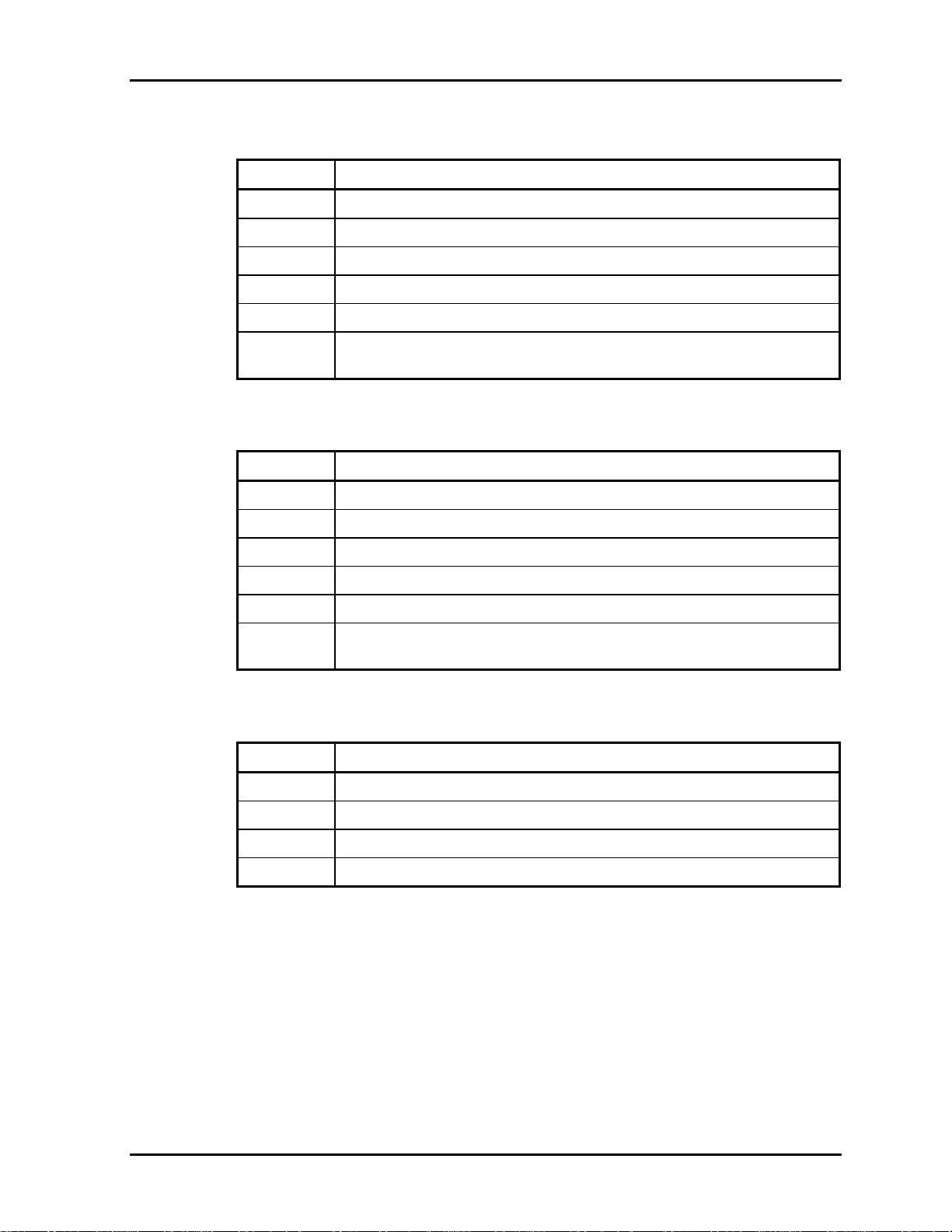
Procedure 3 Antenna Check
Use an antenna test cable to check the antennas' connection. Follow the steps below.
Any of the connections may be disconnected. Disassemble the computer following the steps
described in Chapter 4, perform the following checks
1. Disassemble the computer and disconnect the wireless LAN antennas (white
and black) from the wireless LAN board. Refer to Chapter 4, Replacement
Procedures, for detailed steps of disassembling
2. Connect the tester set up for impedance measurement to the antenna jig.
Measure the white antenna’s resistance
3. Determine the resistance. The antenna passes the test when the resistance is 5Ω
or less. If it is more than 5Ω, the antenna is faulty.
4. Measure the black antenna’s resistance. Check if there is faulty.
Figure 2-3 Antenna Test jig
Measurement Value Pass/fail Comment
5Ω or less
More than 5Ω
Pass Include cable loss
Fail The digital tester shows 0L ,etc. if there is a broken wire.
NOTE: 1. The resistances determined with the steps above may not be stable according
to the length of the antenna. The impedance of the antenna itself is about 0.5
to 0.8 ohm.
2. The above steps cannot accurately determine the impedance of the antenna.
Use an LC meter for a precise measure of impedance.
If each wireless antenna passes the above test, return the Wireless LAN module back, then
perform Procedure 1.
If the wireless LAN has still an error, go to Procedure 4.
2-52 Portege M200 Maintenance Manual (960-457)
Page 59

2.15 Wireless LAN Troubleshooting 2 Troubleshooting
Procedure 4 Replacement Check
Check if the wireless LAN board and the system board are connected properly. If they are
properly connected but there is stall an error, any of these components may be damaged.
Disassemble the computer following the steps described in Chapter 4 and replace the board
with a new one.
Check 1 The wireless LAN board may be defective or damaged. Disassemble the computer
following the steps described in Chapter 4 and replace the board with a new one. If
there is still an error go to Check 2.
Check 2 The system board may be defective or damaged. Disassemble the computer
following the steps described in Chapter 4 and replace the board with a new one.
Portege M200 Maintenance Manual (960-457) 2-53
Page 60

2 Troubleshooting Procedures 2.16 Bluetooth Troubleshooting
2.16 Bluetooth Troubleshooting
This section describes how to determine if the computer's Bluetooth is functioning properly.
Perform the steps below starting with Procedure 1 and continuing with the other procedures as
required.
Procedure 1: Transmitting-Receiving Check
Procedure 2: Antennas' Connection Check
Procedure 3: Antenna Check
Procedure 4: Replacement Check
Procedure 1 Transmitting-Receiving Check
Make sure the wireless switch on the left side of the computer is turned ON. If it is not, slide
the switch toward the back of the computer to turn it on.
Check 1 Execute test program IMCSPC73.EXE to check the BD_ADDR of the Bluetooth.
Perform the test following the instructions described in Chapter 3, Bluetooth Test
Program (IMCSPC73.EXE).
If the computer passes the test, the function is correctly working. If the computer
does not pass the test, the Bluetooth board may be disconnected or damaged.
Make sure the connector on the Bluetooth board is firmly connected to PJ4900 on
the system board. And perform the test program IMCSPC73.EXE again.
If the computer still does not pass the test, go to check 2.
Check 2 Execute test program IMCSPC53.EXE to check the transmitting-receiving
function of the Bluetooth. You will need a second computer that can communicate
by the Bluetooth. Perform the test following the instructions described in Chapter 3,
Bluetooth Test Program (IMCSPC53.EXE).
If the computer passes the test, the function is correctly working.
If the computer does not pass the test, go to check 3.
Check 3 The Bluetooth board may be defective or damaged. Replace it with a new one. And
perform the test program again.
If the computer still does not pass the test, go to Procedure 2.
2-54 Portege M200 Maintenance Manual (960-457)
Page 61

2.16 Bluetooth Troubleshooting 2 Troubleshooting
Procedure 2 Antennas' Connection Check
The Bluetooth function wiring diagram is shown below:
PJ4410
Any of the connections may be disconnected. Disassemble the computer following the steps
described in Chapter 4, Replacement Procedures, and perform the following checks:
Check 1 Make sure the wireless communication switch is “On”.
If the switch is “Off”, turn it “On”. If the Bluetooth module is still not functioning
properly, perform Check 2.
Check 2 Make sure the Bluetooth module is firmly connected to PJ4410 on the system
board.
If the connector is disconnected, connect it firmly and perform Procedure 1. If the
Bluetooth module is still not functioning properly, perform Check 3.
Check 3 Make sure the Bluetooth antenna cable (brown) is firmly connected to the
Bluetooth module.
If the Bluetooth antenna cable is disconnected, connect it firmly and perform
Procedure 1. If the Bluetooth function is still not functioning properly, go to
Procedure 3.
Portege M200 Maintenance Manual (960-457) 2-55
Page 62

2 Troubleshooting Procedures 2.16 Bluetooth Troubleshooting
Procedure 3 Antenna Check
Check 1 Use an antenna test cable to check the antennas' connection. Follow the steps
below:
1. Disassemble the computer and disconnect the Bluetooth antenna cable
connected to the Bluetooth module. Refer to Chapter 4, Replacement
Procedures, for detailed steps of disassembling
2. Connect the end of the antenna test cable to the multimeter.
3. Connect the Bluetooth antenna cable to the antenna test cable. One clip is
connected to the end of the Bluetooth antenna cable. The other is connected to
the opposite side of the Bluetooth antenna cable.
4. Determine the resistance. The cable passes the test when the resistance is 5Ω or
less. If it is more than 5Ω, the Bluetooth antenna cable fails the test.
Figure 2-4 Antenna Test cable
NOTE: 1. The resistances determined with the steps above may not be stable according
to the length of the antenna. The impedance of the antenna itself is about 0.5
to 0.8 ohm.
2. The above steps cannot accurately determine the impedance of the antenna.
Use an LC meter for a precise measure of impedance.
If the Bluetooth antenna cable pass the test, connect it to the Bluetooth module
and cover the slot, then perform Procedure 1.
If the Bluetooth antenna cable does not pass the test, go to Procedure 4.
Procedure 4 Replacement Check
Check 1 The Bluetooth module may be defective or damaged. Replace the Bluetooth
module with a new one following the steps in Chapter 4, Replacement Procedures.
If the Bluetooth is still not functioning properly, perform Check 2.
2-56 Portege M200 Maintenance Manual (960-457)
Page 63

2.16 Bluetooth Troubleshooting 2 Troubleshooting
Check 2 The system board may be defective or damaged. Replace the system board with a
new one following the steps in Chapter 4, Replacement Procedures.
Portege M200 Maintenance Manual (960-457) 2-57
Page 64

2 Troubleshooting Procedures 2.16 Bluetooth Troubleshooting
2-58 Portege M200 Maintenance Manual (960-457)
 Loading...