

Page 1

Chapter 4
Replacement Procedures
Page 2

4 Replacement Procedures
4
4-ii Portege M200 Maintenance Manual (960-457)
Page 3

4 Replacement Procedures
Chapter 4 Contents
4.1 Overview.............................................................................................................. 4-1
Safety Precautions .......................................................................................... 4-2
Before you Begin ........................................................................................... 4-3
Disassembly Procedures ................................................................................ 4-4
Assembly Procedures..................................................................................... 4-5
Tools and Equipment ..................................................................................... 4-5
Screw Tightening Torque .............................................................................. 4-6
Grip Color .................................................................................................... 4-6
Screw Notation............................................................................................... 4-7
4.2 Battery pack ......................................................................................................... 4-8
4.3 PC card/SD memory card .................................................................................. 4-10
4.3.1 PC card................................................................................................ 4-10
4.3.2 SD memory card ................................................................................. 4-10
4.4 Keyboard............................................................................................................ 4-12
4.5 Touch pad........................................................................................................... 4-14
4.6 Memory module................................................................................................. 4-15
4.7 HDD................................................................................................................... 4-17
4.8 Base cover assembly .......................................................................................... 4-19
4.9 Mini PCI............................................................................................................. 4-21
4.10 MDC modem ..................................................................................................... 4-23
4.11 FAN/CPU........................................................................................................... 4-25
4.12 RTC battery........................................................................................................ 4-29
4.13 Bluetooth module............................................................................................... 4-30
4.14 Hinge cables....................................................................................................... 4-32
4.15 System board...................................................................................................... 4-34
4.16 Speaker/LED board............................................................................................ 4-36
4.16.1 Speaker.............................................................................................. 4-36
4.16.2 LED board......................................................................................... 4-37
4.17 Second FAN....................................................................................................... 4-39
4.18 Pen holder/Battery lock/Base latch assembly .................................................... 4-40
4.18.1 Pen holder ......................................................................................... 4-40
4.18.2 Battery lock....................................................................................... 4-41
Portege M200 Maintenance Manual (960-457) 4-iii
Page 4

4 Replacement Procedures
4.18.3 Base latch assembly .......................................................................... 4-42
4.19 LCD unit/FL inverter ......................................................................................... 4-43
4.20 Application switch board/Power switch board/LCD latch assembly................. 4-47
4.20.1 Application switch board/Power switch board ................................. 4-47
4.20.2 LCD latch assembly ......................................................................... 4-48
4.21 Digitizer ............................................................................................................. 4-50
4.22 LCD harness/Hinge assembly............................................................................ 4-56
4.23 Hinge Switch Board ........................................................................................... 4-59
4.24 Fluorescent Lamp............................................................................................... 4-60
4.24.1 Replacing the 12.1 inch Toshiba fluorescent lamp........................... 4-61
Figures
Figure 4-1 Removing the battery pack............................................................................ 4-8
Figure 4-2 Removing the PC card ............................................................................... 4-10
Figure 4-3 Removing the SD memory card.................................................................. 4-11
Figure 4-4 Removing the keyboard ............................................................................. 4-12
Figure 4-5 Removing the Touch Pad ............................................................................ 4-14
Figure 4-6 Removing the memory module................................................................... 4-15
Figure 4-7 Removing the HDD cover........................................................................... 4-17
Figure 4-8 Removing the HDD holder ......................................................................... 4-18
Figure 4-9 Disconnecting the cables............................................................................. 4-19
Figure 4-10 Disconnecting the second FAN cable ....................................................... 4-19
Figure 4-11 Removing the screws ................................................................................ 4-20
Figure 4-12 Removing Mini PCI .................................................................................. 4-21
Figure 4-13 Installing the Wireless LAN antenna cables ............................................. 4-22
Figure 4-14 Removing the MDC modem ..................................................................... 4-23
Figure 4-15 Installing the MDC modem....................................................................... 4-24
Figure 4-16 Removing the FAN ................................................................................... 4-25
Figure 4-17 Removing the FIN..................................................................................... 4-26
Figure 4-18 Removing the CPU ................................................................................... 4-26
Figure 4-19 Applying Silicon Grease ........................................................................... 4-27
Figure 4-20 Installing the FAN cable ........................................................................... 4-27
4-iv Portege M200 Maintenance Manual (960-457)
Page 5

4 Replacement Procedures
Figure 4-21 Removing the RTC battery ....................................................................... 4-29
Figure 4-22 Removing the Bluetooth module .............................................................. 4-30
Figure 4-23 Removing the hinge cable......................................................................... 4-32
Figure 4-24 Removing the system board...................................................................... 4-34
Figure 4-25 Removing the speaker ............................................................................... 4-36
Figure 4-26 Removing the LED board ......................................................................... 4-37
Figure 4-27 Removing the second FAN ....................................................................... 4-39
Figure 4-28 Removing the Pen holder .......................................................................... 4-40
Figure 4-29 Removing the Battery lock........................................................................ 4-41
Figure 4-30 Removing the latch assembly.................................................................... 4-42
Figure 4-31 Removing the LCD mask.......................................................................... 4-43
Figure 4-32 Removing the Cross function button......................................................... 4-44
Figure 4-33 Removing the FL inverter ......................................................................... 4-44
Figure 4-34 Removing the LCD ................................................................................... 4-45
Figure 4-35 Removing the application switch board.................................................... 4-47
Figure 4-36 Removing the power switch board............................................................ 4-47
Figure 4-37 Removing the LCD latch assembly........................................................... 4-48
Figure 4-38 Removing the Digitizer ............................................................................. 4-55
Figure 4-39 Removing the hinge .................................................................................. 4-56
Figure 4-40 Installing the Wireless LAN antenna/Bluetooth antenna.......................... 4-58
Figure 4-41 Removing the hinge switch board............................................................. 4-59
Figure 4-42 to 4-53 Replacing Toshiba fluorescent lamp (1) to (10) ...............4-61 to 4-68
Portege M200 Maintenance Manual (960-457) 4-v
Page 6

4 Replacement Procedures
4-vi Portege M200 Maintenance Manual (960-457)
Page 7
4.1 Overview 4 Replacement Procedures
4 Replacement Procedures
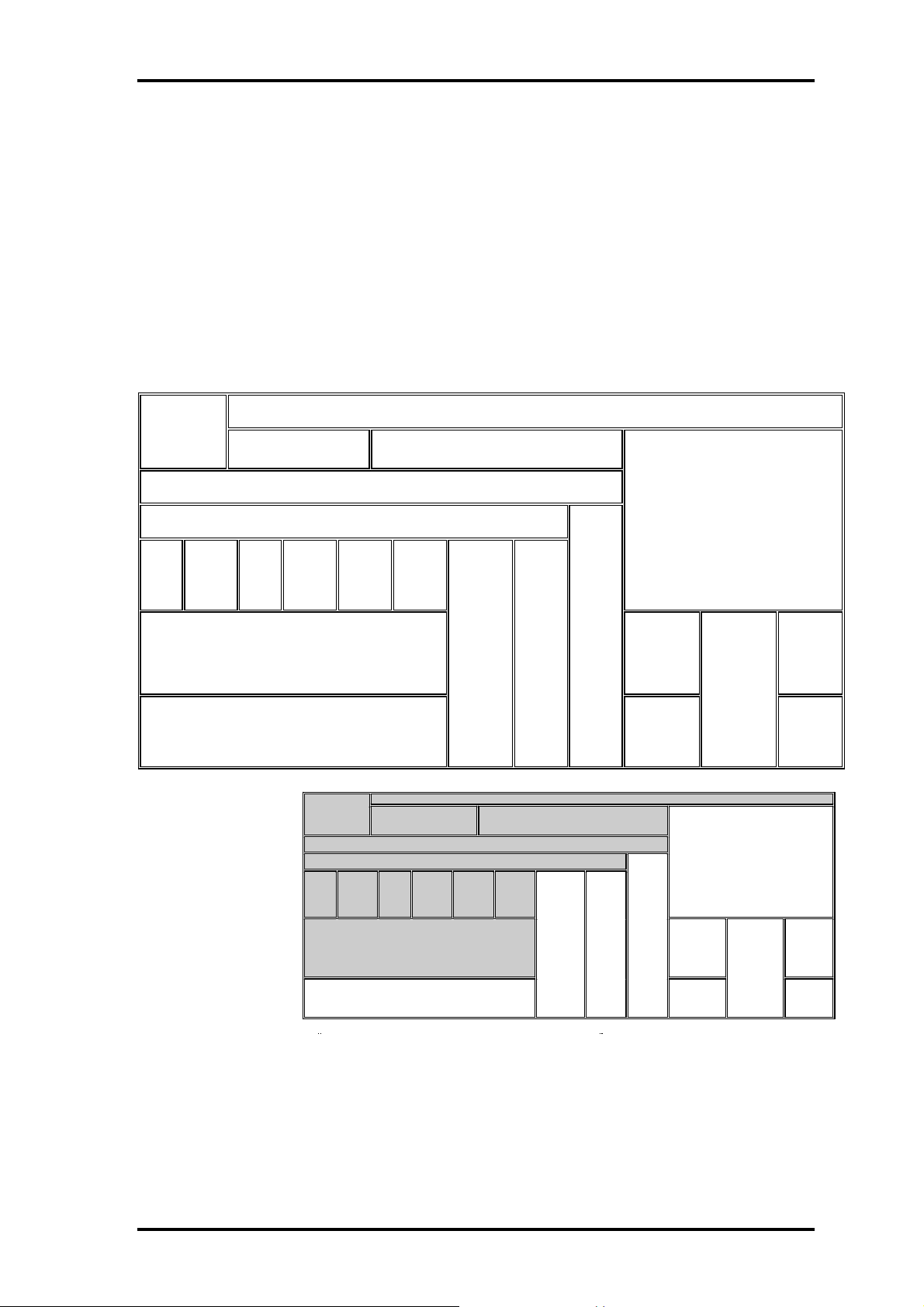
4.1 Overview
This chapter describes the procedure for removing and replacing the field replaceable
units (FRUs) in the PC. It may not be necessary to remove all the FRUs in order to
replace one. The chart below provides a guide as to which other FRUs must be removed
before a particular FRU can be removed. The numbers in the chart indicate the relevant
section numbers in this manual.
In all cases when removing an FRU, the battery pack must also be removed. When
repairing an FRU that is the potential cause of a computer fault, use the chart to determine
the order in which FRUs need to be removed.
PC card
4.2 Battery pack 4.3
SD memory
card
4.6 Memory module 4.7 HDD
4.4 Keyboard
4.8 Base cover assembly
4.9
Mini
PCI
4.10
MDC
modem
4.6
FAN/
CPU
4.15 System board
4.16 Speaker/LED board
Chart Notation
The chart shows the case for the
following example:
Removing the system board
All FRUs down to the “4.9
Mini PCI” to “4.14 Hinge cable”
units immediately above the
system board must be removed.
Similarly, as this requires the
removal of all the units from
“4.3 PC card” to “4.8Base cover
assembly” must be also
removed.
4.12
RTC
battery
4.13
Blue
tooth
module
4.3
PC card/
SD memory
card
4.4 Keyboard
4.8 Base cover ass embly
4.9
4.10
Mini
MDC
PCI
modem
4.15 System board
4.16 Speaker/LED board
4.14
Hinge
cable
4.18
Pen
holder/
Battery
lock/
Base
latch
assembly
(Example)
4.2 Battery pack
4.6 Memory module 4.7 HDD
4.6
4.12
RTC
battery
4.13
Blue
tooth
module
FAN/
CPU
4.14
Hinge
cable
4.17
Second
FAN
4.18
Pen
holder/
Battery
lock/
Base
latch
assembly
4.5
Touch
pad
4.17
Second
FAN
4.19
LCD/FL inverter
4.21
Digitizer
4.24
Florescent
lamp
4.19
LCD/FL inverter
4.5
Touch
4.21
pad
Digitizer
4.24
Florescent
lamp
4.8
Application
Switch/
Power
switch/
LCD latch
assembly
4.8
Application
Switch/
Power
switch/
LCD latch
assembly
4.22
LCD
harness/
Hinge
assembly
4.23
Hinge
Switch
board
4.22
LCD
harness/
Hinge
assembly
4.23
Hinge
Switch
board
Portege M200 Maintenance Manual (960-457) 4-1
Page 8

4 Replacement Procedures 4.1 Overview
Safety Precautions
Please read the following safety instructions before disassembling the computer and
always follow the instructions while working on the computer.
Danger: 1. In the case of the battery, always use authentic parts or equivalent parts
approved by Toshiba. Other batteries may have different specifications
that are incompatible with the computer and may result in fire or
explosion.
Due to the risk of alkali fluid leaks, never attempt to heat or disassemble
the battery. Similarly, due to the risk of explosion, never expose the
battery to flame.
2. Some parts including the power supply and FL inverter generate high
voltages. If you need to turn on the power while disassembling the
computer, do not touch any connectors or other components due to the
risk of electric shock. Also, do not disassemble individual parts when
performing routine maintenance.
Warning:1. To prevent electric shock, turn off the power and unplug the AC adapter
from the power source.
2. As the battery installed to the computer is typically already charged, the
risk of electric shock remains even when the AC adapter is unplugged
from the socket. To prevent electric shock, always take off any metal
jewelry or accessories such as necklaces, bracelets or rings before
working on the computer. Never work with wet or moist hands.
3. Take care not to injury yourself on any edges or corners.
Caution: 1. Confirm that replacement parts have compatible specifications before
replacing on the computer. Never use incorrect parts as these may cause
faults on the computer.
2. To prevent internal damage such as short circuits or burning, do not allow
any screws, paper clips, or other metal objects to fall into the computer.
When removing screws, always replace with the same size screw. Ensure
that all screws are fully tightened. Loose screws may result in short
circuits leading to overheating, smoke or flame.
3. To prevent electric shock, check that you have disconnected all cables
from a part before removing the part.
4. When connecting to the AC power supply, use only an AC adapter and
cable approved by Toshiba.
5. To prevent electric shock, ensure that all replacement parts are
compatible with the computer and that all cables and connectors are
securely connected.
4-2 Portege M200 Maintenance Manual (960-457)
Page 9

4.1 Overview 4 Replacement Procedures
Before You Begin
Take note of the following points before starting work. Always remove the AC adapter
and battery pack before commencing any of the procedures. The procedure for removing
the battery pack is described in section “4.2.1 Battery Pack”.
1. Do not disassemble the computer unless it is operating abnormally.
2. Use the designated tools.
3. Ensure that the environment for working on and storing parts does not contain any
of the following.
❑ Dust or dirt
❑ Static electricity
❑ Extremely hot, cold, or humid conditions
4. Perform the diagnostic tests described in Chapter 2 to determine which FRU is the
cause of the fault.
5. Do not perform any unnecessary work. Always work in accordance with the
disassembly and re-assembly procedures in this manual.
6. Keep parts removed from the computer in a safe place away from the computer
where they will not be damaged or interfere with your work.
7. Disassembling requires the removal of a large number of screws. Keep removed
screws in a safe place such that you can determine which screws belong to which
part.
8. When reassembling, ensure that you use the correct screws and fit parts in the
correct position. Screw sizes are noted in the text and figures.
9. As all parts have sharp edges and corners, take care not to cut yourself.
10. After replacing an FRU, check that the computer and replaced part operate
correctly.
Portege M200 Maintenance Manual (960-457) 4-3
Page 10
4 Replacement Procedures 4.1 Overview
Disassembly Procedures
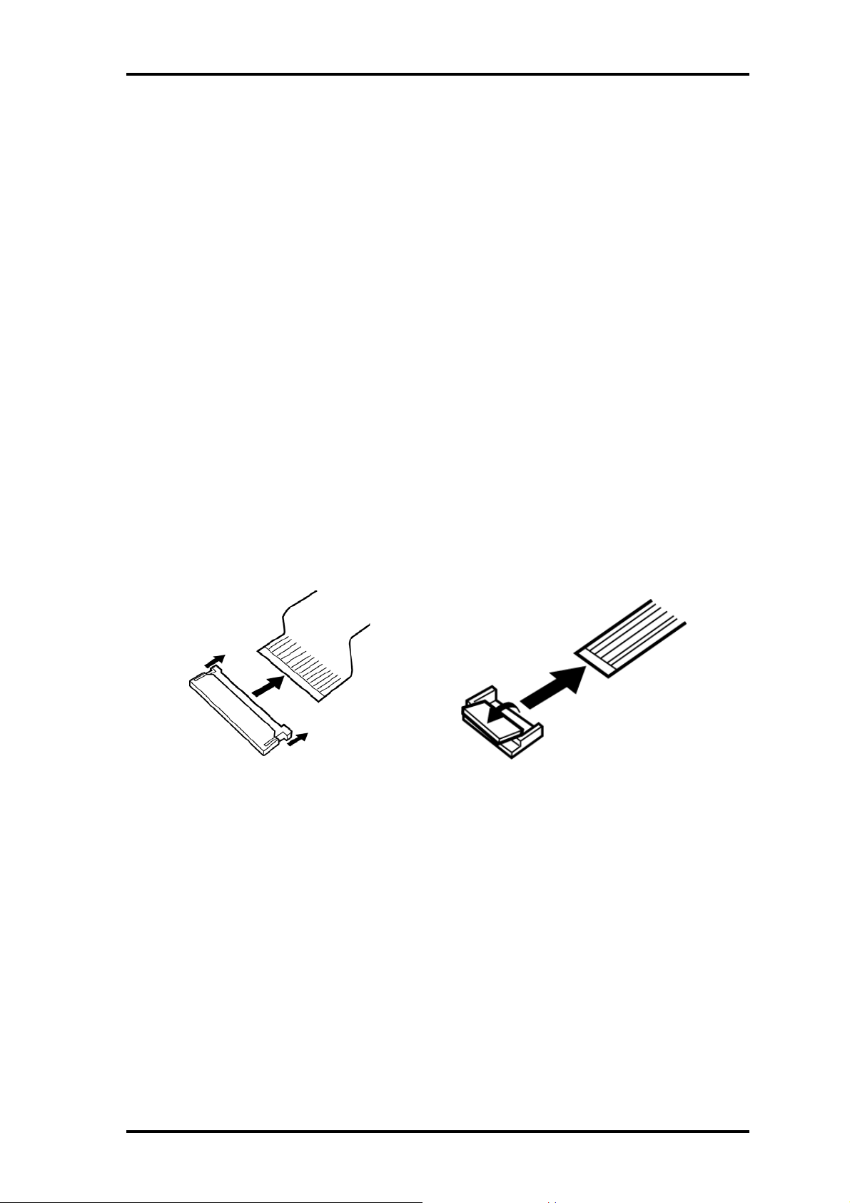
Three main types of cable connector are used.
❑ Pressure plate connector
❑ Spring connector
❑ Normal pin connector
When disconnecting a pressure plate connector, draw the tab on one side of the plastic
pressure plate on the connector and pull the cable out from the connector. When
reconnecting a cable to a pressure plate connector, draw enough the pressure plate and
insert the cable into the connector. Press both sides of the pressure plate such that both
sides of the plate and connector are at the same height and that the cable is fixed in the
correct position. Pull the cable to ensure that it is securely connected. If the cable is
disconnected from the connector, reconnect it making sure that you draw enough the
pressure plate to insert fully the cable.
For spring connectors, lifting up the stopper frees the cable and allows it to be pulled out.
To reconnect, hold the stopper in the up position and insert the cable, then lower the
stopper to secure the cable.
Normal pin connectors are used for all other cables. Simply pull out or push in these
connectors to disconnect or reconnect.
Pressure plate connector
Spring connector
4-4 Portege M200 Maintenance Manual (960-457)
Page 11

4.1 Overview 4 Replacement Procedures
Assembly Procedure
After the computer has been disassembled and the part that caused the fault has been
repaired or replaced, the computer must be reassembled.
Take note of the following general points when assembling the computer.
❑ Take your time and follow the instructions carefully. Hurrying the assembly work
will only introduce new problems.
❑ Check that all cables and connectors are securely connected.
❑ Before fastening FRUs or other parts in place, ensure that no cables are caught on
screws or the FRU.
❑ Check that all latches are securely closed.
❑ Ensure that you have installed all FRUs correctly and do not have any screws left
over. Using an incorrect screw may damage the thread or screw head and result in
the FRU not being securely fastened in place.
After installing FRUs, check that the computer operates correctly.
Tools and Equipment
For your safety and the safety of the people around you, it is important that you use
Electrostatic Discharge (ESD) equipment. Correctly utilizing of the equipment increases
the percentage of successful repairs and saves on the cost of damaged or destroyed parts.
The following equipment is required for disassembly and assembly.
❑
One Philips screwdriver with type 0 bit (for THIN HEAD screws)
❑ One Philips screwdriver with type 1 bit (for screws other than above)
❑ Tweezers (for lifting screws)
❑ ESD mats (lay on work table or floor)
❑ An ESD wrist strap and heel grounder
❑ Anti-static carpet or flooring
❑ A pair of needle-nose pliers
❑ Air-ionizers in highly static sensitive areas
❑ Antenna coaxial cable disconnector
Portege M200 Maintenance Manual (960-457) 4-5
Page 12
4 Replacement Procedures 4.1 Overview
Screw Tightening Torque
Use the following torque when tightening screws.
Caution: Overtightening may damage screws or parts. Undertightening may allow
screws to loosen (and possibly fall out) causing a short circuit or other
damage.
Note: To tighten screws quickly and accurately, an electric screwdriver is
recommended.
❑ M2 (2mm) 0.167 N•m (1.7 kgf •cm)
❑ M2.5 (2.5mm) 0.294 N•m(3.0 kgf•cm)
❑ M3 (3mm) 0.549 N•m(5.6 kgf•cm)
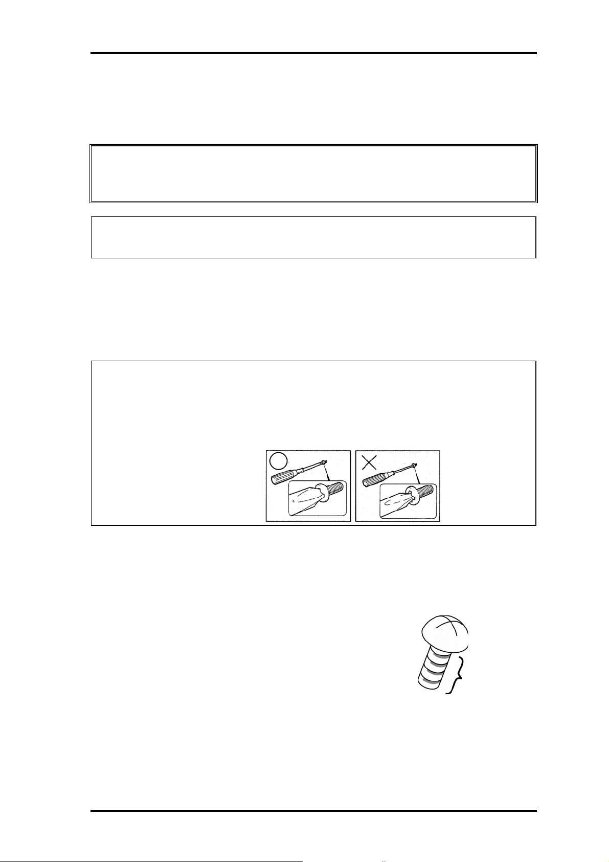
Note: To prevent damage to THIN HEAD screws, use type 0 pit philips screwdriver.
Use, however, the PH point size “1” screwdriver for screws fixing the expansion
memory slot cover and the keyboard.. Press along the axis of the screwdriver
while turning the screw. This is because the contact area between the screw and
driver is less than for a pan head screw (standard pan-shaped screw head).
Grip Color
Some screws have a colored grip area to help you determine the length of the screw.
❑ Even numbered length screws: Brown
❑ Odd numbered length screws: White
❑ Special length screw: Blue
“Special length screw” means screws whose length is indicated
Grip area
in an integral number to the first decimal places such as 2.5 mm,
2.6 mm and so on.
4-6 Portege M200 Maintenance Manual (960-457)
Page 13

4.1 Overview 4 Replacement Procedures
Screw Notation
To make maintenance of the computer easier, markings of the kinds of the screws
including the types and lengths of the screws are indicated on the computer body.
Format:
Screw shape + Screw length (mm)
Screw shape
B: Bind screw
F: Flat head screw
S: Super thin head screw
T: Tapping screw
U: Other screws (Unique screws: pan head, stud, etc.)
Example:
B6
... 6mm BIND screw
Portege M200 Maintenance Manual (960-457) 4-7
Page 14
4 Replacement Procedures 4.2 Battery pack
4.2 Battery pack
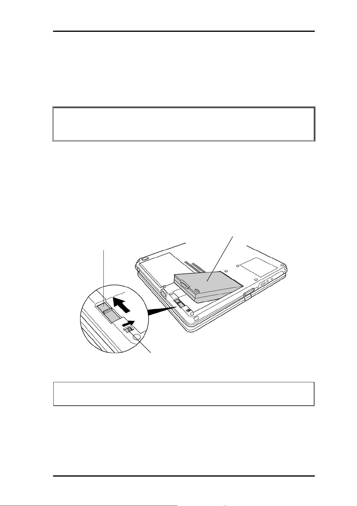
Removing the battery pack
The following describes the procedure for removing the battery pack. (See Figure 4-1.)
Caution: Take care not to short circuit the terminals when removing the battery pack.
Similarly, do not drop, knock, scratch, disassemble, twist, or bend the battery
pack.
1. Turn off the power of the computer.
2. Disconnect the AC adapter and all other external devices from the computer.
3. Turn the computer upside down.
4. Release the battery lock switch.
5. Slide the battery latch in the direction indicated by the arrow to loosen the lock.
Pull out the battery to remove.
Battery pack
Battery latch
Battery lock switch
Figure 4-1 Removing the battery pack
Note: Dispose of the used battery pack in accordance with the laws and ordinances of
your local authority.
4-8 Portege M200 Maintenance Manual (960-457)
Page 15

4.2 Battery pack 4 Replacement Procedures
Installing the battery pack
The following describes the procedure for installing the battery pack. (See Figure 4-1.)
Caution: There is a danger that the lithium ion battery pack may explode if not fitted,
operated, handled, or disposed correctly. Dispose of the used batteries pack
in accordance with the laws and ordinances of your local authority. Use only
the batteries approved by Toshiba.
Note: Check visually the battery terminals and clean off any dirt with a dry cloth.
1. Turn off the power of the computer.
2. Disconnect the AC adapter and all other external devices from the computer.
3. Inset the connector of the battery to the connector of the computer. Press the
battery pack until the battery is locked.
4. Secure the battery lock.
Portege M200 Maintenance Manual (960-457) 4-9
Page 16
4 Replacement Procedures 4.3 PC Card/SD memory card
4.3 PC Card/SD memory card
4.3.1 PC Card
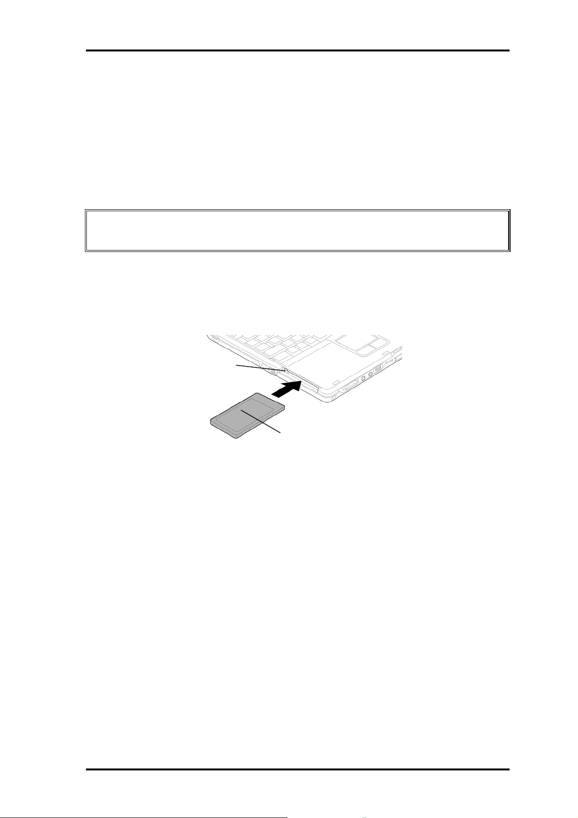
Removing the PC Card
The following describes the procedure for removing the PC card. (See Figure 4-2.)
Caution: Insert or remove the PC Card in accordance with any instructions in the PC
Card manual or the manuals of the computer system you are using.
1. Push the ejection button. It will pop out when you release it. Press it once more to
eject the PC Card.
2. Pull out the and remove it.
Eject button
PC card
Figure 4-2 Removing the PC card
Installing the PC Card
The following describes the procedure for installing the PC card. (See Figure 4-2.)
1. Make sure the eject button does not stick out.
2. Insert the PC Card and press it until it is securely connected.
4.3.2 SD memory card
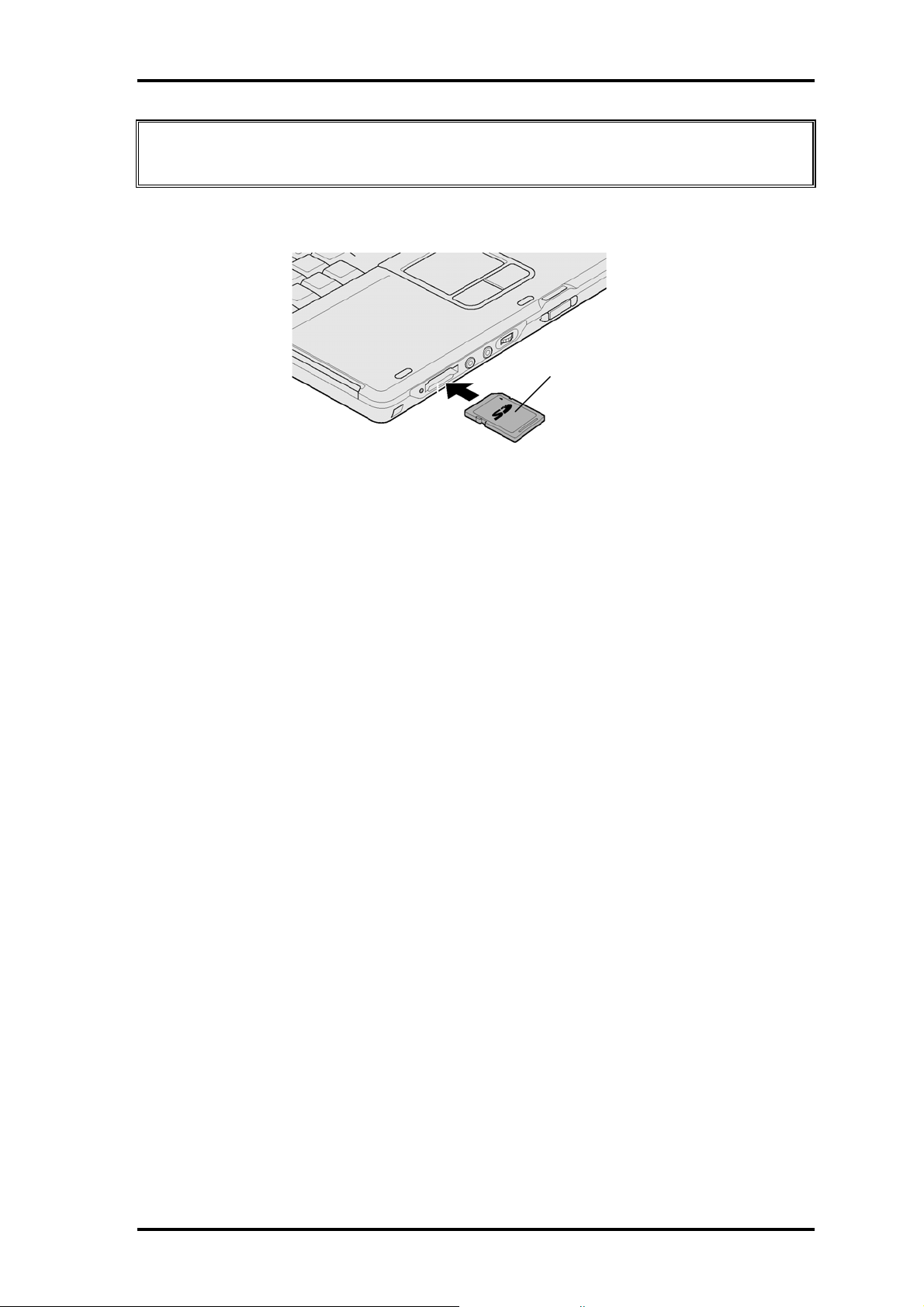
Removing the SD memory card
The following describes the procedure for removing the SD memory card. (See Figure 4-
3.)
4-10 Portege M200 Maintenance Manual (960-457)
Page 17
4.3 PC Card/SD memory card 4 Replacement Procedures
Caution: Insert or remove the SD card in accordance with any instructions in the SD
card manual or the manuals of the computer system you are using.
1.Push the SD memory card. It will pop out partly when you release, so pull out the card.
SD memory card
Figure 4-3 Removing the SD memory card
Installing the SD memory card
The following procedure describes the procedure for installing the SD memory card. (See
Figure 4-3.)
1.Insert the SD memory card and press it until it securely connected.
Portege M200 Maintenance Manual (960-457) 4-11
Page 18
4 Replacement Procedures 4.4 Keyboard
r
4.4 Keyboard
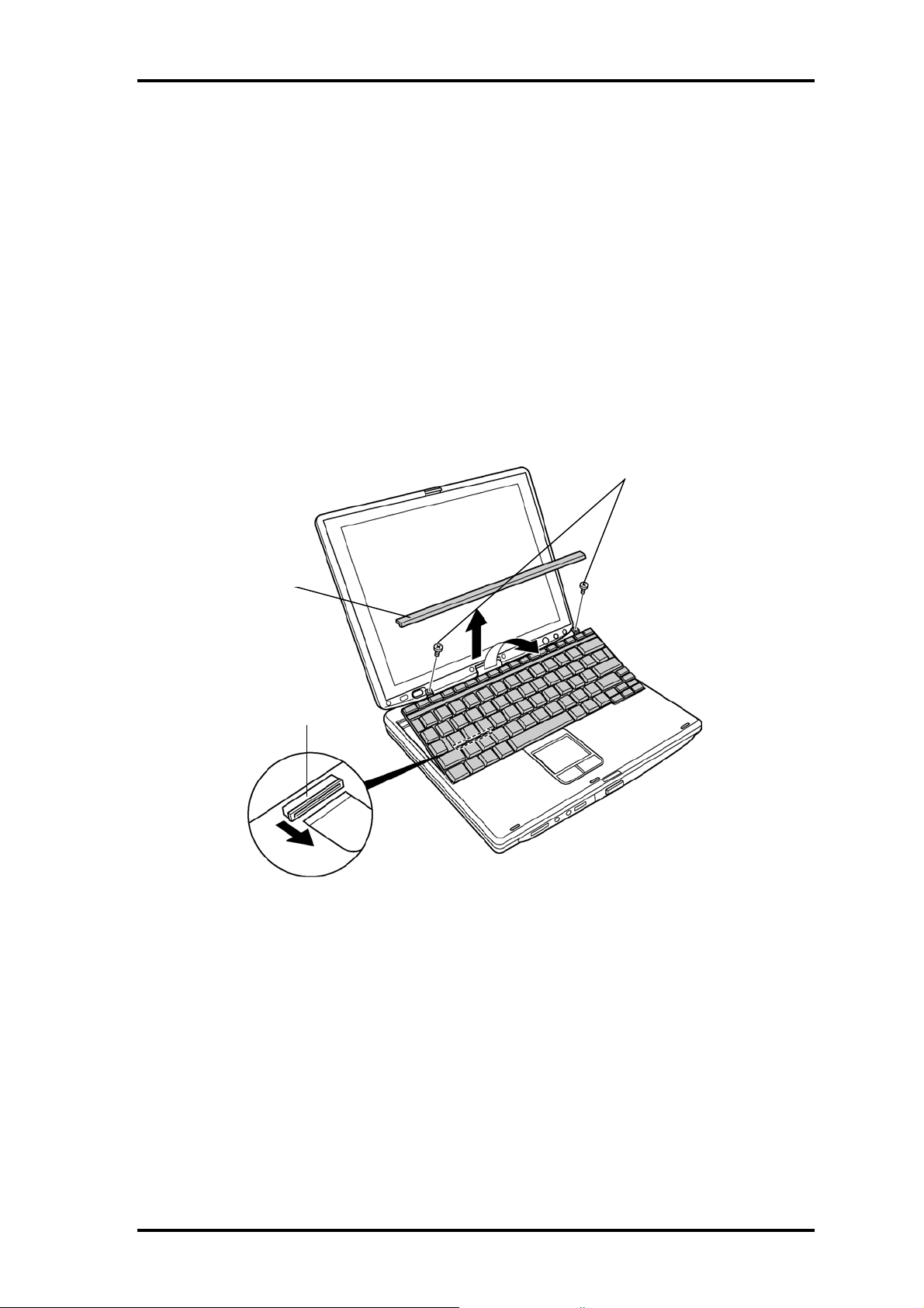
Removing the keyboard
The following describes the procedure for removing the keyboard. (See Figure 4-4.)
1. Open the display.
2. Insert your nails in the slot of both sides of the keyboard holder and lift it up to
remove.
3. Remove the following screws securing the keyboard.
• M2.5×2.8B FLAT BIND screw x2
M2.5 x 2.8B FLAT BIND
Keyboard holde
PJ3230
Figure 4-4 Removing the keyboard
4. Lift the top edge of the keyboard and bring the edge to the front to lay on the
computer. Unlock the connector and disconnect the flexible keyboard cable from
the connector on the system board.
5. Remove the keyboard.
4-12 Portege M200 Maintenance Manual (960-457)
Page 19

4.4 Keyboard 4 Replacement Procedures
Installing the keyboard
The following describes the procedure for installing the keyboard. (See Figure 4-4.)
1. Put the keyboard on the palm rest as its face is down. Connect the flexible
keyboard cable to PJ3230 on the system board and lock the connector.
2. Hook the bottom edge of the keyboard to the palm rest. Place the keyboard on the
computer and secure it with the following screws.
• M2.5×2.8B FLAT BIND screw x2
3. Install the keyboard holder.
Portege M200 Maintenance Manual (960-457) 4-13
Page 20
4 Replacement Procedures 4.5 Touch pad
4.5 Touch pad
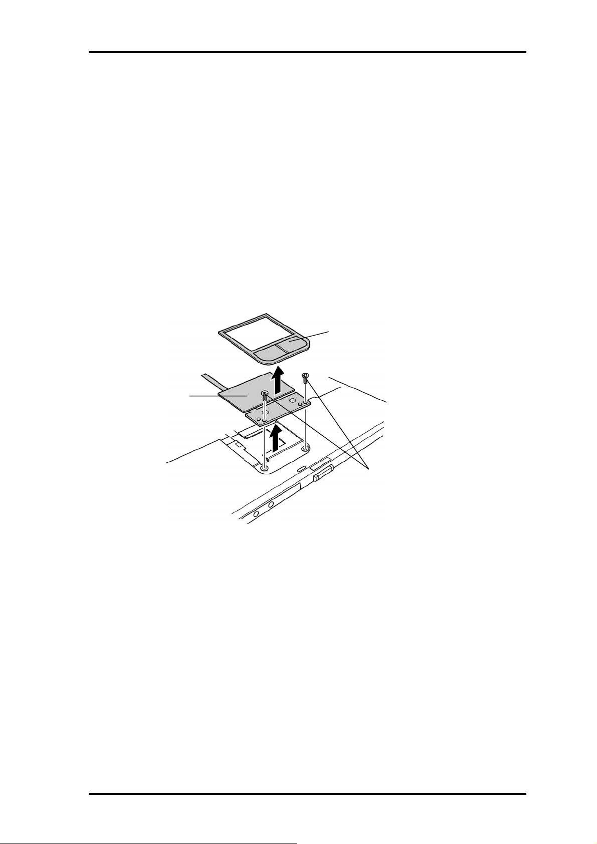
Removing the touch pad
The following describes the procedure for removing the touch pad. (See Figure 4-5.)
1. Disconnect the flat cable from the connector on the system board.
2. Pull the touch pad holder slantwise from the computer.
3. Remove the following screws securing the touch pad.
• M2.5×3B S-THIN screw x2
4. Remove the touch pad from the computer.
5. Disconnect the flat cable from the touch pad.
Touch Pad Holder
Touch Pad
M2.5x3B S-THIN
Figure 4-5 Removing the Touch Pad
Installing the touch pad
The following describes the procedure for installing the touch pad (See Figure 4-5.).
1. Connect the flat cable to the touch pad.
2. Install the touch pad on the computer.
3. Secure the touch pad with the following screws.
• M2.5×3B S-THIN screw x2
4. Insert the touch pad holder into the touch pad slot slantwise.
5. Connect the flat cable to the connector PJ3240 on the system board.
4-14 Portege M200 Maintenance Manual (960-457)
Page 21
4.6 Memory module 4 Replacement Procedures
4.6 Memory module
Caution: The power must be turned off when you remove the memory module.
Removing a memory module with the power on risks damaging the module
or the computer itself.
Do not touch the memory module terminals. Any dirt on the terminals may
cause memory access problems.
Never press hard or bend the memory module.
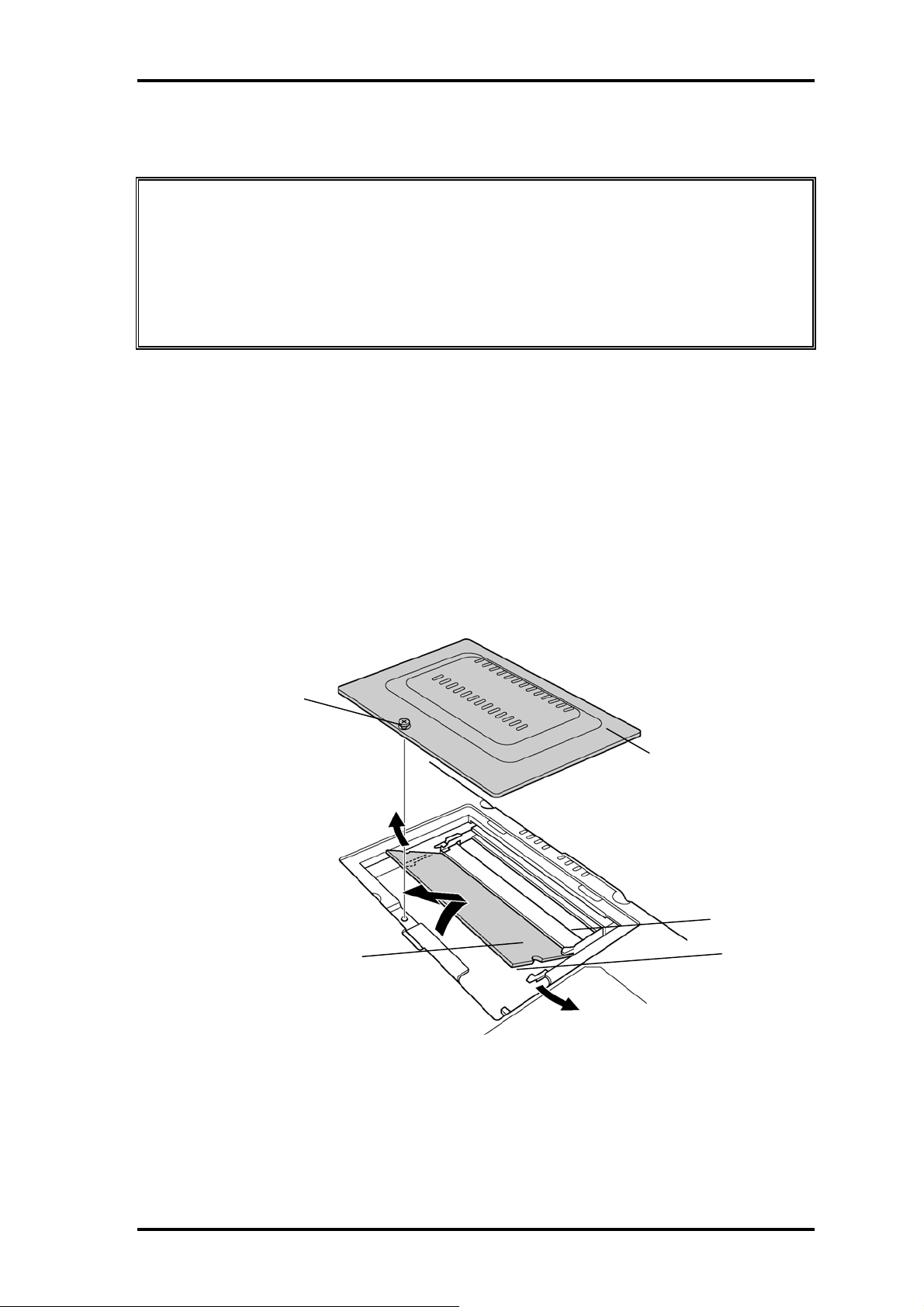
Removing the memory module
To remove the memory module(s), confirm that the computer is in boot mode. Then
perform the following procedure. (See Figure 4-6.)
1. Turn the computer upside down.
2. Loosen the screw with e-ring fixing the memory slot cover.
3. Remove the memory slot cover.
4. Open the left and right latches and remove the memory module(s).
Screw with e-ring
Memory slot cover
Memory module
Slot A
Slot B
Figure 4-6 Removing the memory module
Portege M200 Maintenance Manual (960-457) 4-15
Page 22

4 Replacement Procedures 4.6 Memory module
Installing the memory module
To install the memory module(s), confirm that the computer is in boot mode. Then
perform the following procedure. (See Figure 4-6.)
1. Insert the memory module into the connector of the computer slantwise (terminal
side first) and press it to connect firmly.
Caution: The power must be turned off when you insert the memory module. Inserting
a memory module with the power on risks damaging the module or the
computer itself.
Never press hard or bend the memory module.
When installing a memory module, be sure to install the memory module into
the slot B.
2. Install the memory slot cover.
3. Secure the screw with e-ring to fix the memory slot cover.
4-16 Portege M200 Maintenance Manual (960-457)
Page 23
4.7 HDD 4 Replacement Procedures
4.7 HDD
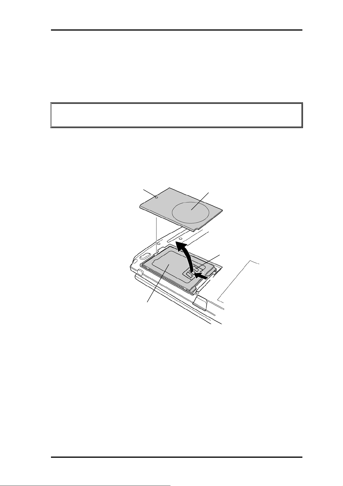
Removing the HDD
The following describes the procedure for removing the HDD. (See Figure 4-7 to 4-8.)
Caution: Take care not to press on the top or bottom of the HDD. Pressure may cause
data loss or damage to the device.
1. Turn the computer upside down.
2. Loosen the screw with e-ring securing the HDD slot cover and remove the cover.
3. Hold the HDD holder tab and pull the HDD assembly to the arrow direction (1) in
the figure below and remove the HDD assembly.
Screw with e-ring
HDD assembly
Figure 4-7 Removing the HDD cover
HDD slot cover
HDD holder tab
(1)
Portege M200 Maintenance Manual (960-457) 4-17
Page 24

4 Replacement Procedures 4.7 HDD
4. Remove the following screws fixing the HDD holder.
• M3×4S FLAT screw x4
5. Detach the HDD holder from the HDD.
M3 x 4S FLAT
HDD Holder
M3 x 4S FLAT
Figure 4-8 Removing the HDD holder
Installing the HDD
The following describes the procedure for installing the HDD. (See Figure 4-7 to 4-8.)
1. Install the HDD holder to the HDD with the following screws.
• M3×4S FLAT screw x4
2. Set the HDD assembly to the HDD slot from the opposite side of the connector.
3. Insert the HDD assembly into the connector on the system board with holding the
HDD holder tab.
4. Install the HDD slot cover from the opposite side of the screw and secure it with
the screw with e-ring.
4-18 Portege M200 Maintenance Manual (960-457)
Page 25

4.8 Base cover assembly 4 Replacement Procedures
4.8 Base cover assembly
Removing the base cover assembly
The following describes the procedure for removing the base cover assembly. (See Figure
4-9 to 4-11.)
1. After Peeling off the glass tape, turn up the insulator and disconnect the speaker
cable.
2. After turning up the insulator, unlock the connector and disconnect the LED
flexible cable and the Touch Pad flexible cable.
Glass tape
PJ3260
LED flexible cable
PJ3240
Touch Pad flexible cable
Speaker cable
PJ6005
Figure 4-9 Disconnecting the cables
3. Close the display and turn the computer upside down.
4. Disconnect the second FAN cable from the system board near the memory slot.
Insert the cable under the
chassis after connecting it
to the connector on the
Memory slot
system board.
PJ8425
Second FAN cable
Figure 4-10 Disconnecting the second FAN cable
Portege M200 Maintenance Manual (960-457) 4-19
Page 26

4 Replacement Procedures 4.8 Base cover assembly
5. Remove the following screws from the bottom of the computer.
• M2.5×6B FLAT BIND screw x19 (Described as 6 in the figure)
• M2.5×3B S-THIN screw x1 (Described as 3 in the figure)
6
6
6
6
6
6
6
6
6
6
6
6
6
Figure 4-11 Removing screws
6. Pull up the base cover assembly to remove.
6
6
6
6
6
6
3
Installing the base cover assembly
The following describes the procedure for installing the base assembly. (See Figure 4-9 to
4-11.)
1. Install the base cover assembly on the base assembly and hook the latches.
2. Secure the base cover assembly with the following screws.
• M2.5×6B FLAT BIND screw x19
• M2.5×3B S-THIN screw x1
3. Connect the second FAN cable to the connector on the system board near the
memory slot and push the cable into the slot of the computer.
4. Turn over the computer.
5. Turn up the insulator and connect the LED flexible cable and Touch Pad flexible
cable to the connector PJ3260 and PJ3240.
6. Turn up the insulator and connect the speaker cable to the connector PJ6005.
Stick the glass tape to secure the insulator on the speaker cable.
4-20 Portege M200 Maintenance Manual (960-457)
Page 27

4.9 Mini PCI 4 Replacement Procedures
4.9 Mini PCI
Removing the Mini PCI
The following describes the procedure for removing a Mini PCI. (See Figure 4-12.)
Caution: The power must be turned off when you remove the mini PCI. Removing a
mini PCI with the power on risks damaging the module or the computer
itself.
Never press hard or bend the mini PCI.
1. Remove the following screws securing the mini PCI cover and remove the mini
PCI cover.
• M2×4Z BIND screw x2
or
• M2×4B LH STICK screw x2
2. Disconnect the wireless LAN antenna cables from the mini PCI.
3. Open the left and right latches securing the mini PCI and remove the mini PCI.
M2 x 4Z BIND
or
M2 x 4B LH STICK
Wireless LAN Antenna Cable
Mini PCI cover
Mini PCI (Wireless LAN) Module
Figure 4-12 Removing the Mini PCI
Portege M200 Maintenance Manual (960-457) 4-21
Page 28

4 Replacement Procedures 4.9 Mini PCI
A
Installing the Mini PCI
The following describes the procedure for removing a Mini PCI. (See Figure 4-12 to 4-
13.)
1. Insert the mini PCI slantwise into the connector on the system board. Press the
mini PCI until it hooks surely.
2. Connect the Wireless LAN antenna cable to the mini PCI. Connect the white cable
to the Main connector and the black one to the Sub connector.
Black cable (Sub)
White cable (Main)
Glass tape
rrange the Wireless LAN
antenna cables on the
MDC modem (Not on the
label of the MDC modem)
Figure 4-13 Installing the Wireless LAN antenna cables
3. Secure the mini PCI cover with the following screws.
• M2×4Z BIND screw x2
or
• M2×4B LH STICK screw x2
4-22 Portege M200 Maintenance Manual (960-457)
Page 29

4.10 MDC modem 4 Replacement Procedures
4.10 MDC modem
Removing the MDC modem
The following describes the procedure for removing an MDC modem. (See Figure 4-14.)
Caution: The power must be turned off when you remove the MDC modem. Removing
an MDC modem with the power on risks damaging the modem or the
computer itself.
1. Remove the following screws securing the MDC modem.
• M2×4Z BIND screw x2
2. Remove the MDC modem from the connector on the system board.
3. Disconnect the cable from the MDC modem.
4. After peeling off the glass tape, turn up the insulator and disconnect the MDC
modem cable from the connector on the system board.
M2 x 4Z BIND
MDC modem
PJ3020
Figure 4-14 Removing the MDC Modem
Portege M200 Maintenance Manual (960-457) 4-23
Page 30

4 Replacement Procedures 4.10 MDC modem
t
Installing the MDC modem
The following describes the procedure for installing an MDC modem. (See Figure 4-14 to
4-15.)
1. Connect the MDC modem cable to the MDC modem.
2. Connect the MDC modem to the connector PJ3020 on the system board and
secure it with the following screws
• M2×4Z BIND screw x2
3. After turning up the insulator, arrange the MDC modem cable and connect to the
connector PJ3021 on the system board. Stick the glass tape.
Caution: When installing the MDC modem cable, make sure the cable does not cover
screw holes and is caught by the Fan.
PJ3021
Run the cable through the
wo holes of the insulator.
Make sure that the cable
passes over the fin pipe.
Run the cable between the
MDC modem and mini PCI.
Lightly pull the cable not to give the
looseness on the MDC modem side.
Run the cable outside of the stud
screw of the CPU hold plate.
Lightly pull the cable not to give the
looseness on the MDC modem side.
Figure 4-15 Installing the MDC Modem
4-24 Portege M200 Maintenance Manual (960-457)
Page 31

4.11 FAN/CPU 4 Replacement Procedures
4.11 FAN/CPU
Removing the FAN/CPU
The following describes the procedure for removing the FAN/CPU. (See Figure 4-16 to
4-18.)
1. Remove the following screws securing the FAN unit.
• M2.5×4B FLAT BIND screw x2
2. Disconnect the FAN cable from the connector on the system board.
3. Remove the FAN and peel off the glass tape covering the FAN cable.
4. Disconnect the rotation sensor cable from the connector on the system board.
Glass tape
M2.5x4B FLAT BIND
PJ8400
FAN
Make sure that
rotation sensor cable
runs over the fin pipe.
Rotation sensor cable
PJ3280
Figure 4-16 Removing the FAN
5. Remove the following screws securing the CPU holder in the order of the marks
(4 to 1) on the CPU hold plate.
• M2×4Z BIND screw x4
6. Remove the FIN on the CPU.
Portege M200 Maintenance Manual (960-457) 4-25
Page 32

4 Replacement Procedures 4.11 FAN/CPU
M2x4Z BIND
CPU Hold plate
Figure 4-17 Removing the FIN
7. Unlock the CPU by rotating counterclockwise the cam on the CPU socket by 90
degrees with a flat-blade driver.
8. Remove the CPU.
Figure 4-18 Removing the CPU
Installing the FAN/CPU
The following describes the procedure for installing the FAN/CPU. (See Figure 4-16 to 4-
20.)
1. Make sure that the cam of the CPU socket is in the unlock position.
2. Install the CPU on the CPU socket and check the CPU is installed on the right
position.
3. Lock the CPU by rotating clockwise the cam on the CPU socket by 90 degrees
with a flat-blade driver.
4-26 Portege M200 Maintenance Manual (960-457)
Page 33

4.11 FAN/CPU 4 Replacement Procedures
4. If there is already silicon grease on the CPU and FIN, clean it with a cloth.
Using a special applicator, apply silicon grease so that the CPU chip on the CPU
is completely covered.
Note: Apply the silicon grease enough to cover the chip surface using the
special applicator. The amount is 0.25ml.
Figure 4-19 Applying Silicon Crease
5. Install the FIN on the CPU. Install the CPU hold plate on them and secure it with
the following screws in the order of the marks (1 to 4) on the CPU hold plate.
• M2×4Z BIND screw x4
6. Connect the rotation sensor cable to the connector PJ3280 on the system board.
7. Set the FAN cable along the side of the FAN and secure it with the glass tape.
8. Connect the FAN cable to the connector PJ8400 on the system board.
Caution: Make sure the FAN cable does not pass on the memory connectors.
FAN cable
Glass tape
PJ8400
Figure 4-20 Installing the FAN cable
Portege M200 Maintenance Manual (960-457) 4-27
Page 34

4 Replacement Procedures 4.11 FAN/CPU
9. Install the FAN and secure it with the following screws.
• M2×4B BIND screw x4
4-28 Portege M200 Maintenance Manual (960-457)
Page 35

4.12 RTC battery 4 Replacement Procedures
4.12 RTC battery
Removing the RTC battery
The following describes the procedure for removing the RTC battery. (See Figure 4-21.)
1. Remove the RTC battery from the Battery holder.
2. Disconnect the RTC battery cable from the connector on the system board.
RTC battery
RTC battery cable passes
around the frame of the holder.
Figure 4-21 Removing the RTC battery
Installing the RTC battery
The following describes the procedure for installing the RTC battery. (See Figure 4-21.)
1. Connect the RTC battery cable to the connector on the system board.
2. After arranging the cable passing around the frame of the holder, install the RTC
battery in the RTC battery holder.
Portege M200 Maintenance Manual (960-457) 4-29
Page 36

4 Replacement Procedures 4.13 Bluetooth module
4.13 Bluetooth module
Removing the Bluetooth module
The following describes the procedure for removing the Bluetooth module. (See Figure 4-
22.)
1. Peel off the insulator.
2. After releasing the connector lock, disconnect the flat cable from the connector on
the system board and Bluetooth module.
3. Remove the Bluetooth antenna harness from the Bluetooth. Module.
4. Remove the following screws securing Bluetooth module.
• M2×4Z BIND screw x1
M2 x 4Z BIND
Bluetooth module
Flat cable
Figure 4-22 Removing the Bluetooth module
Installing the Bluetooth module
The following describes the procedure for installing the Bluetooth module. (See Figure 4-
22.)
1. Install the Bluetooth module and secure it with following screw.
• M2×4Z BIND screw x1
2. Connect the Bluetooth antenna harness to the Bluetooth module.
3. Connect the flat cable to the connector PJ4410 on the system board and Bluetooth
module and lock the connectors.
4-30 Portege M200 Maintenance Manual (960-457)
Page 37

4.13 Bluetooth module 4 Replacement Procedures
4. Stick the insulator.
Note: When the Bluetooth module is not installed, secure the antenna
harness with the glass tape on the insulator.
Portege M200 Maintenance Manual (960-457) 4-31
Page 38

4 Replacement Procedures 4.14 Hinge cables
4.14 Hinge cables
Removing the hinge cables
The following describes the procedure for removing the hinge cables. (See Figure 4-23.)
1. Peel off two glass tapes securing the hinge cables.
2. Disconnect the microphone cable and LCD cable from the connector on the
system board.
3. Disconnect the Digitizer cable and LCD power cable.
4. Remove carefully the hinge cables from the guide of the base assembly.
Bluetooth antenna harness
LCD cable
Glass tape
Microphone cable
Glass tape
Insulator
Digitizer cable
LCD power cable
Wireless LAN antenna cable
Figure 4-23 Removing the hinge cable
Installing the hinge cables
The following describes the procedure for installing the hinge cables (See Figure 4-23).
1. Connect the Digitizer cable and LCD power cable to the connector on the system
board.
2. Install carefully the hinge cables in the guide of the base assembly.
4-32 Portege M200 Maintenance Manual (960-457)
Page 39

4.14 Hinge cables 4 Replacement Procedures
Note: Arrange the Wireless LAN antenna cable and microphone cable running
between RGB connector and the connectors PJ3540, PJ5206.
Arrange the LCD cable running over the connectors PJ3540, PJ5206.
RGB connector
PJ5206
PJ3540
Wireless LAN antenna cable/
Microphone cable
LCD cable
3. Connect the microphone cable and LCD cable to the connector PJ6000 and
PJ5205 on the system board. Stick the two glass tapes to secure them.
Caution: Arrange the microphone cable running in the copper portion on the
laminate sheet.
Caution: Make sure that the glass tape covering the digitizer cable and LCD power
cable is lower than the connector panel.
Portege M200 Maintenance Manual (960-457) 4-33
Page 40

4 Replacement Procedures 4.15 System board
Y
4.15 System board
Removing the system board
The following describes the procedure for removing the system board. (See Figure 4-24.)
NOTE: When removing/installing the system board, be careful not to scratch the
cables.
1. Remove the following screws securing the system board and remove the system
board.
• M2.5×4B FLAT BIND screw x6
2. Remove the sound JACK cover from the system board.
3. Remove the FIR cover ASSY from the base assembly.
M2.5x4B FLAT BIND
System board
Sound JACK cover
FIR cover ASS
Figure 4-24 Removing the system board
4-34 Portege M200 Maintenance Manual (960-457)
Page 41

4.15 System board 4 Replacement Procedures
Installing the system board
The following describes the procedure for installing the system board. (See Figure 4-24.)
1. Install the sound JACK cover to the system board.
2. Install the system board to the base assembly from the hinge side and secure it
with the following screws.
• M2.5×4B FLAT BIND screw x6
NOTE: When installing the system board, make sure that the switch of the system
board fits to the FIR cover ASSY and works correctly.
And also, confirm the rotation sensor cable is on the system board.
3. Install the FIR cover ASSY to the base assembly.
Portege M200 Maintenance Manual (960-457) 4-35
Page 42

4 Replacement Procedures 4.16 Speaker/LED board
A
4.16 Speaker/LED board
4.16.1 Speaker
Removing the speaker
The following describes the procedure for removing the speaker. (See Figure 4-25.)
1. Remove the following screws securing the speaker holder and remove the speaker
holder.
• M2.5×3B S-THIN screw x2
2. Remove the speaker from the speaker holder.
M2.5x3B S-THIN
rrange the speaker cable
passing through the frame
and on the insulator.
Figure 4-25 Removing the speaker
Installing the speaker
The following describes the procedure for installing the speaker. (See Figure 4-25.)
1. Set the speaker to the speaker holder.
2. Install the speaker holder on the base assembly and secure it with the following
screws.
• M2.5×3B S-THIN screw x2
4-36 Portege M200 Maintenance Manual (960-457)
Page 43

4.16 Speaker/LED board 4 Replacement Procedures
4.16.2 LED board
Removing the LED board
The following describes the procedure for removing the LED board. (See Figure 4-26.)
1. Remove the following screws securing the LED board and remove LED lens
holder.
• M2.5×2.8B FLAT BIND screw x1
2. Disconnect the flat cable from the LED board.
3. Remove the LED board from the LED lens holder.
Flat cable
LED board
M2.5x2.8B FLAT BIND
LED lens holder
Figure 4-26 Removing the LED board
Installing the LED board
The following describes the procedure for installing the LED board. (See Figure 4-26.)
1. Install the LED board to the LED lens holder.
2. Connect the flat cable to the LED board and system board.
3. Install the LED lens holder to the base assembly and secure it with the following
screws.
• M2.5×2.8B FLAT BIND screw x1
Portege M200 Maintenance Manual (960-457) 4-37
Page 44

4 Replacement Procedures 4.16 Speaker/LED board
NOTE: After installing the LED lens holder, make sure the flat cable comes
on the insulator of the base cover assembly.
4-38 Portege M200 Maintenance Manual (960-457)
Page 45

4.17 Second FAN 4 Replacement Procedures
4.17 Second FAN
Removing the Second FAN
The following describes the procedure for removing the Second FAN. (See Figure 4-27.)
1. Remove the following screws securing the Second FAN unit.
• M2.5×4B FLAT BIND screw x2
2. Remove the Second FAN unit from the base cover assembly.
M2.5x4B FLAT BIND
Second FAN
Figure 4-27 Removing the Second FAN
Installing the Second FAN
The following describes the procedure for installing the Second FAN. (See Figure 4-27.)
1. Install the Second FAN unit on the base cover assembly.
2. Secure the Second FAN unit with the following screws.
• M2.5×4B FLAT BIND screw x2
Portege M200 Maintenance Manual (960-457) 4-39
Page 46

4 Replacement Procedures 4.18 Pen holder/Battery lock/Latch assembly
4.18 Pen holder/Battery lock/Latch assembly
4.18.1 Pen holder
Removing the Pen holder
The following describes the procedure for removing the Pen holder. (See Figure 4-28.)
1. Remove the following screws securing the pen holder.
• M2.5×4B FLAT BIND screw x2
2. Remove the pen holder from the base cover.
M2.5x4B FLAT BIND
Pen Holder
Figure 4-28 Removing the Pen holder
Installing the Pen holder
The following describes the procedure for installing the Pen holder. (See Figure 4-28.)
1. Install the pen holder on the base cover.
2. Secure the pen holder with the following screws.
• M2.5×4B FLAT BIND screw x2
4-40 Portege M200 Maintenance Manual (960-457)
Page 47

4.18 Pen holder/Battery lock/Latch assembly 4 Replacement Procedures
4.18.2 Battery lock
Removing the Battery lock
The following describes the procedure for removing the Battery lock (See Figure 4-29.)
1. Remove the following screws securing the Battery lock.
• M2.5×4B FLAT BIND screw x2
2. Remove the Battery lock from the base cover.
M2.5x4B FLAT BIND
Battery lock
Figure 4-29 Removing the Battery lock
Installing the Battery lock
The following describes the procedure for installing the Battery lock (See Figure 4-29)
1. Install the Battery lock on the base cover.
2. Secure the Battery lock with the following screws.
• M2.5×4B FLAT BIND screw x2
Portege M200 Maintenance Manual (960-457) 4-41
Page 48

4 Replacement Procedures 4.18 Pen holder/Battery lock/Latch assembly
4.18.3 Base latch assembly
Removing the Base latch assembly
The following describes the procedure for removing the Base latch assembly (See Figure
4-30.)
1. Remove the following screws securing the base latch assembly.
• M2.5×4B FLAT BIND screw x2
2. Remove the base latch assembly from the base cover.
M2.5x4B FLAT BIND
Base latch assembly
Figure 4-30 Removing the latch assembly
Installing the Base latch assembly
The following describes the procedure for installing the Base latch assembly (See Figure
4-30)
1. Install the base latch assembly to the base cover.
2. Secure the base latch assembly with the following screws.
• M2.5×4B FLAT BIND screw x2
4-42 Portege M200 Maintenance Manual (960-457)
Page 49

4.19 LCD unit/FL inverter 4 Replacement Procedures
4.19 LCD unit/FL inverter
Removing the LCD unit and FL inverter
The following describes the procedure for removing the LCD unit and FL inverter. (See
Figure 4-31 to 4-34.)
NOTE: When removing the LCD unit or FL inverter, do not press the LCD part of the
base cover assembly. It may cause the breakage of the hinge assembly.
Use a stand or something to make the LCD part flat for installing the LCD
unit and FL inverter, and to make the base assembly floating from the ground.
1. Remove the four mask cushions from the LCD cover by using a needle.
Remove the two mask seals from the display mask.
2. Remove the following screws securing the LCD cover.
• M2.5×6B FLAT BIND screw x6 (Described as 6 in the figure)
3. Open the display until LCD and the base assembly become horizontal. Insert your
nails into slit of the LCD and release the latches from the bottom side of the LCD.
Slit for releasing the latches
6
6
6
6
6
Mask seal
6
Mask cushion
Figure 4-31 Removing the LCD mask
Portege M200 Maintenance Manual (960-457) 4-43
Page 50

4 Replacement Procedures 4.19 LCD unit/FL inverter
4. Remove the Cross function button.
Cross function button
Figure 4-32 Removing the Cross function button
5. Remove the following screw fixing the FL inverter. After peeling off the insulator,
remove the harness from both sides and remove the FL inverter.
• M2×4Z BIND screw x1
M2x4Z BIND
Insulator
FL inverter
Figure 4-33 Removing the FL Inverter
6. Remove the following screws fixing the LCD unit.
• M2 ×4Z BIND screw x4
7. With the bottom edge of the LCD unit on the display cover, raise the top edge of the
LCD unit. Remove the glass tapes to remove two LCD cables from the connector on
the back of the LCD.
4-44 Portege M200 Maintenance Manual (960-457)
Page 51

4.19 LCD unit/FL inverter 4 Replacement Procedures
NOTE: When putting the LCD unit on the display cover, lay a mat or something on
under the LCD unit to protect the computer and the LCD from a scratch or
breakage.
M2x4Z BIND
Glass tape
Glass tape
Figure 4-34 Removing the LCD
Installing the LCD unit and FL inverter
The following describes the procedure for installing the LCD unit and FL inverter. (See
Figure 4-31 to 4-34.)
1. With the LCD unit standing on the display cover, connect two LCD cables on the
back of LCD and secure them with two glass tapes.
2. Lay down the LCD on the LCD cover and secure it with the following screws.
• M2×4Z BIND screw x4
3. Connect the two harnesses to the connector of the FL inverter. Secure the FL inverter
with the following screw. Secure the FL inverter with the following screw.
• M2×4Z BIND screw x1
4. Install the cross function button
5. Install the LCD mask. Press the LCD mask until latches fasten securely.
NOTE: When installing the LCD mask, wipe the LCD mask with a soft cloth and make
the back of the LCD mask clean with an ionizer.
And also, make sure that the cross function button is installed.
Portege M200 Maintenance Manual (960-457) 4-45
Page 52

4 Replacement Procedures 4.19 LCD unit/FL inverter
6. Secure the LCD mask with the following screws and put the mask seals and mask
cushions on them.
• M2.5×6B FLAT BIND screw x6
4-46 Portege M200 Maintenance Manual (960-457)
Page 53

4.20 Application switch board/Power switch board/LCD latch assembly 4 Replacement
A
Procedures
4.20 Application switch board/Power switch board/LCD latch
assembly
4.20.1 Application switch board/Power switch board
Removing the Application switch board/Power switch board
The following describes the procedure for removing the Application switch board/Power
switch board. (See Figure 4-35 to 4-36.)
1. Remove the following screws securing the application switchboard and remove the
application switchboard.
• M2 ×4Z BIND screw x1
M2x4Z BIND
pplication switch board
Figure 4-35 Removing the application switch board
2. Disconnect the harness from the connector on the application switchboard.
3. Remove the following screws securing the Power switchboard and remove the
Power switchboard.
• M2 ×4Z BIND screw x1
M2x4Z BIND
Power Switch board
Figure 4-36 Removing the power switch board
Portege M200 Maintenance Manual (960-457) 4-47
Page 54

4 Replacement Procedures 4.20 Application switch board/Power switch board/LCD
latch assembly
Installing the Application switchboard/Power switchboard
The following describes the procedure for installing the Application switchboard/Power
switchboard (See Figure 4-35 to 4-36.)
1. Connect the harness to the connector on the application switchboard. Install the
application switchboard along the guide pin on the both side and secure it with the
following screws.
• M2×4Z BIND screw x1
2. Connect the harness to the connector on the power switchboard. Install the power
switchboard along the guide pin on the both side and secure it with the following
screws.
• M2×4Z BIND screw x1
4.20.2 LCD latch assembly
Removing the LCD latch assembly
The following describes the procedure for removing the LCD latch assembly (See Figure
4-37.)
1. Remove the following screws securing the LCD latch assembly and remove the
LCD latch assembly.
• M2.5×4Z FLAT BIND screw x1
M2.5x4Z FLAT BIND
LCD latch assembly
Figure 4-37 Removing the LCD latch assembly
4-48 Portege M200 Maintenance Manual (960-457)
Page 55

4.20 Application switch board/Power switch board/LCD latch assembly 4 Replacement
Procedures
Installing the LCD latch assembly
The following describes the procedure for installing the LCD latch assembly (See Figure
4-37.)
1. Install the LCD latch assembly and secure it with the following screw.
• M2.5×4Z FLAT BIND screw x1
Portege M200 Maintenance Manual (960-457) 4-49
Page 56

4 Replacement Procedures 4.21 Digitizer
4.21 Digitizer
Caution: Read following instructions before handling the Digitizer.
Do not carry the LCD module by holding the FL cable in one’s hand because it may
result to cut the FL cable, and cause display function failure or lighting failure.
NO
Do not carry the LCD module by
holding the FL cable in one’s
hand.
Be careful to use the bezel guide.
There is a portion where the bezel is sticking out because of the digitizer guide. Do not
press and rub the portion with bare hands or it may result cut your finger.
NO
Be careful to use the bezel guide.
4-50 Portege M200 Maintenance Manual (960-457)
Page 57

4.21 Digitizer 4 Replacement Procedures
Do not make any scratches on the B/L and TAB by the edge of the digitizer when
installing the digitizer because it may result to break the TAB or make scratches on the
B/L and cause display function failure.
NO
Digitizer
Do not hit the corner of the digitizer
Do not pull up the PCB hardly when installing the digitizer because it may result to
give stress on the TAB or PCB and cause the display function failure.
NO
Digitizer
PCB
Do not pull up the PCB.
Portege M200 Maintenance Manual (960-457) 4-51
Page 58

4 Replacement Procedures 4.21 Digitizer
Make sure that three latches fit the digitizer securely.
If the latches are not locked securely, it may result to move the digitizer and give stress
on the TAB or PCB and cause the display function failure.
NO
Digitizer is not fit in
the latches.
OK
Digitizer is fit in the latches.
4-52 Portege M200 Maintenance Manual (960-457)
Page 59

4.21 Digitizer 4 Replacement Procedures
Do not turn up the digitizer because it may result to give stress on the TAB or PCB
and cause the display function failure.
NO
Digitizer
PCB
TAB
Do not turn up the digitizer to avoid the warp of the
PCB.
Do not put any instrument on the LCD module because it may result to make scratch
on the cell, polarization sheet or B/L and break the TAB and may cause the display
function failure.
NO
Chassis
Do not put the chassis on the LCD.
Do not put the instrument on the LCD.
Portege M200 Maintenance Manual (960-457) 4-53
Page 60

4 Replacement Procedures 4.21 Digitizer
Do not hold, press and rub the TAB because it may result to break the TAB and cause
the display function failure.
NO
TAB
PCB
Do not hold the TAB.
TAB
Do not press the TAB. Do not rub the TAB.
Make sure to put the LCD module on the flat place. If the LCD module is put on the
uneven place, it may result to break the TAB, make scratch on the B/L or polarization
sheet and cause the display function failure.
NO
FL inverter
Do not put the LCD on the
chassis when the LCD is not
installed to the computer.
Do not put the LCD on the FL inverter.
4-54 Portege M200 Maintenance Manual (960-457)
Page 61

4.21 Digitizer 4 Replacement Procedures
Removing the Digitizer
The following describes the procedure for removing the digitizer. (See Figure 4-38.)
1. Peel off two tapes securing the digitizer.
2. Remove the following screws securing the digitizer.
• M2×4Z BIND screw x2
3. Pull the digitizer toward the arrow direction in the figure below and remove the
digitizer.
Glass tape
M2x4Z BIND
Glass tape
Figure 4-38 Removing the Digitizer
Installing the digitizer
The following describes the procedure for installing the digitizer. (See Figure 4-38.)
1. Slide the digitizer into the back of the LCD.
2. Secure the digitizer with the following screws.
• M2×4Z BIND screw x2
3. Stick two glass tapes to secure the digitizer.
Portege M200 Maintenance Manual (960-457) 4-55
Page 62

4 Replacement Procedures 4.22 LCD harness / Hinge assembly
4.22 LCD harness / Hinge assembly
Removing the LCD harness and hinge assembly
The following describes the procedure for removing the LCD harness and hinge assembly.
(See Figure 4-39.)
1. Remove the following screws securing the hinge assembly.
• M2.5×6B FLAT BIND screw x2 (Described as 6B in the figure)
• M2.5×6C FLAT BIND screw x2 (Described as 6C in the figure)
2. Remove the hinge rear cover and hinge assembly from the base assembly by turning
the hinge counterclockwise by 90 degrees.
3. Remove the following screw securing the LCD harness hold plate.
• M2×2.8B FLAT BIND screw x1 (Described as 2.8 in the figure)
4. Remove the following screws securing the hinge on the both sides.
• M2.5×6B FLAT BIND screw x4 (Described as 6B in the figure)
LCD earth plate
6B
6B
6C
6B
6B
LCD harness hold plate
6B
6C
2.8
6B
Figure 4-39 Removing the hinge
5. Remove the LCD earth plates securing the both sides of the cables.
6. Peel off the six acetate tapes securing the wireless LAN antenna cables, Bluetooth
cable and microphone cable.
7. Remove the microphone cables.
8. Remove the LCD harness.
4-56 Portege M200 Maintenance Manual (960-457)
Page 63

4.22 LCD harness / Hinge assembly 4 Replacement Procedures
Installing the LCD harness and the hinge assembly
The following describes the procedure for installing the LCD harness and the hinge
assembly. (See Figure 4-39 to 4-40.)
1. Pass the LCD harness and microphone cable through the hole of the hinge.
2. Install the hinge assembly and secure it with the following screws.
• M2.5×6B FLAT BIND screw x4 (Described as 6B in the figure)
3. Arrange the cables along the guide to the both sides and secure them with the LCD
earth plate.
4. Install the LCD harness hold plate for holding the LCD harness and secure it with the
following screw.
• M2×2.8B FLAT BIND screw x1 (Described as 2.8 in the figure)
5. Turn the hinge plate counterclockwise by 90 degrees. Install the hinge rear cover and
secure it with the following screws.
• M2.5×6B FLAT BIND screw x2 (Described as 6B in the figure)
• M2.5×6C FLAT BIND screw x2 (Described as 6C in the figure)
6. Hold the LCD cover facing you and attach the following antennas with double-faced
tapes in the order of the main wireless LAN antenna (with white cable), Bluetooth
antenna (with brown cable) and sub wireless LAN antenna (with black cable).
NOTE: When installing the Wireless LAN antennas and Bluetooth antenna, make sure
to install them along the mark line of the computer.
And also, make sure of the position of each antenna cable installed on the
antenna.
7. Install the microphones to the guide pin.
8. Arrange the cables form each antenna and stick six acetate tapes for securing the
cables.
Caution: Place each cable from the hinge assembly in the order of wireless LAN
cable, microphone cable and LCD harness.
Portege M200 Maintenance Manual (960-457) 4-57
Page 64

4 Replacement Procedures 4.22 LCD harness / Hinge assembly
microphone
Microphone cable
Wireless LAN antenna
Bluetooth antenna
Wireless LAN antenna
Make sure of the position of
antenna cables attached on the
antenna.
Figure 4-40 Installing the Wireless LAN antenna/Bluetooth antenna
4-58 Portege M200 Maintenance Manual (960-457)
Page 65

4.23 Hinge Switch Board 4 Replacement Procedures
4.23 Hinge Switch Board
Removing the hinge switch board
The following describes the procedure for removing the hinge switch board. (See Figure
4-41.)
1. Remove the following screw to remove the hinge switch board.
• M2×3B FLAT BIND screw x2
2. Remove the plate placed under the hinge switch board.
M2x3B FLAT BIND
Hinge switch board
Plate
Figure 4-41 Removing the hinge switch board
Installing the hinge switch board
The following describes the procedure for installing hinge switch board. (See Figure 4-
41.)
1. Install the plate fitting to the bosses on the hinge assembly and put the hinge switch
board on it.
2. Secure the hinge switch board with the following screws.
• M2×3B FLAT BIND screw x2)
Portege M200 Maintenance Manual (960-457) 4-59
Page 66

4 Replacement Procedures 4.24 Fluorescent Lamp
4.24 Fluorescent Lamp
This system uses LCD modules from the following suppliers. The procedure for replacing
the fluorescent lamp is different for each LCD module. Refer to the appropriate procedure.
Type Part.No Supplier Section
12.1 inch G33C00019110 Toshiba 4.24.1
Note: - When working with an LCD module, always use a flat, grounded table.
- Handle the backlight unit in the environment without dust, such as on the clean
bench. Keep the worktable free from any screws or other material that may
scratch the LCD surface.
- Use an anti-static or protective sheet.
- When replacing the FL unit, cover with a finger protector or similar to prevent
dirtying or scratching the LCD panel.
- Take care when handling the lamp. Excessive force may break the lamp.
- Take care not to dirty or deform the lamp reflector.
- Ensure always that the power of the LCD module is turned off before
connecting or disconnecting cables and connectors.
4-60 Portege M200 Maintenance Manual (960-457)
Page 67

4.24 Fluorescent Lamp 4 Replacement Procedures
4.24.1 Replacing the 12.1 Inch Toshiba Fluorescent Lamp
The following describes the procedure for replacing the fluorescent lamp. (See Figure 442 to 4-53.)
Disassembling the module
1. Peel off tapes and insulating sheets.
1) Place carefully the module face up on a clean and flat worktable. To avoid
scratching the face of the LCD module, make sure the table is free of dirt and
dust. Place a protection sheet (soft cloth or similar one) over the front of the
module.
2) Peel off the double-faced tape of the insulation sheet side. (Do not peel off the
tape on the bezel side.)
Caution: 1) Be careful not to damage the TAB, PCB, B/L and reflection sheet.
2) Leave the insulation sheet on the bezel to reuse it later.
3)Be careful not to damage the TAB and PCB when peeling off double-faced
tape on the insulation sheet.
Side tape of insulation sheet
Double-faced tape of insulation sheet
Bezel tape
Bezel tape
Figure 4-42 Replacing Toshiba fluorescent lamp(1)
Portege M200 Maintenance Manual (960-457) 4-61
Page 68

4 Replacement Procedures 4.24 Fluorescent Lamp
2. Removing screws
1) Peel off the bezel tapes
2) Spread out the insulation sheet without detaching from the bezel side, as shown
in the drawing below.
Insulation sheet
Bezel tape
Bezel tape
Figure 4-43 Replacing Toshiba fluorescent lamp(2)
3) Remove the screws.(4 screws)
Caution: Use a Philips screwdriver with type 0 bit to remove the screws.
Screws
Screws
Figure 4-44 Replacing Toshiba fluorescent lamp(3)
4-62 Portege M200 Maintenance Manual (960-457)
Page 69

4.24 Fluorescent Lamp 4 Replacement Procedures
3. Removing the bezel
1) Place the module with the insulation sheet facing upwards.
2) Release two latches for the side edge of the bezel and frame. Pulling up the
bezel from the bottom side (FL lamp side), release four latches for the top edge
of the bezel and remove the bezel from the cell.
(The bezel with double-faced tape will be reused.)
Caution: 1)When peeling off the double-faced tapes, be careful not to damage the
TAB.
2)When removing the bezel, peel off the double-faced tape on the bezel
bottom carefully and do not break it and do not deform the bezel. (The bezel
with double-faced tape will be reused.)
Release the latch for top
Remove the bezel while peeling
off the double-faced tape
Release the latch for
Figure 4-45 Replacing Toshiba fluorescent lamp(4)
4. Spread out the PCB
1) Spread out the PCB horizontally as shown in the drawing below.
Release the latch for side
Pull up the bezel from bottom side
Remove the bezel while peeling
off the double-faced tape
Portege M200 Maintenance Manual (960-457) 4-63
Page 70

4 Replacement Procedures 4.24 Fluorescent Lamp
Caution: Be careful not to damage the TAB.
Figure 4-46 Replacing Toshiba fluorescent lamp(5)
5. Removing the cell with the PCB
1) Remove the cell with the PCB from the backlight unit as shown in the drawing
below.
2) Peel off the double-faced tape on the back of the cell cleanly.
Caution: 1)The cell in the top side is attached to the frame with double-faced tape so
that remove the cell carefully not to break it.
2)Be careful not to peel off the shading tape on the four sides.
3)Be careful not to damage the TAB.
Remove the cell while peeling off
the double-faced tape.
Figure 4-47 Replacing Toshiba fluorescent lamp(6)
4-64 Portege M200 Maintenance Manual (960-457)
Page 71

4.24 Fluorescent Lamp 4 Replacement Procedures
Assembling the module
Assembling procedure is a same as the preceding paragraph “Disassembling the module”
but practice in reverse.
1. Checking the backlight
Make sure the sheet stays in the frame.
Double-faced tape
Make sure the sheet fit in the frame.
Make sure the sheet stays in the
Figure 4-48 Replacing Toshiba fluorescent lamp(7)
2. Assembling the cell with the PCB
1) Peel off the separation sheet of the double-faced tape on the top of the frame.
2) Illuminate the backlight.
3) Make sure there is no scratch or dirt on the backlight. Also check the back of the
cell. Next, install the cell with the PCB to the backlight unit.
Caution: 1) Install by aligning to the bottom left corner as shown below.
2) Be careful not to damage the TAB.
Portege M200 Maintenance Manual (960-457) 4-65
Page 72

4 Replacement Procedures 4.24 Fluorescent Lamp
Set the cell to the left of the bezel.
Peel off the separation sheet
from the double-faced tape.
Figure 4-49 Replacing Toshiba fluorescent lamp(8)
3. Folding and temporary fixing the TAB / PCB
1) Fold the TAB (PCB) around the back of the backlight unit as shown below.
Caution: Be careful not to damage the TAB.
Figure 4-50 Replacing Toshiba fluorescent lamp(9)
4. Installing the bezel
1) Hook the latch on the top of the bezel (TAB side).
2) Hook the two latches on the side of the bezel (one latch for each side).
3) Set the bezel on the frame from the bottom side.
4-66 Portege M200 Maintenance Manual (960-457)
Page 73

4.24 Fluorescent Lamp 4 Replacement Procedures
Caution: Be careful not to damage the cell, TAB and B/L.
Hook the latch on the top.
Hook the latch on the side.
Set the bezel on the frame.
Hook the latch on the side.
Figure 4-51 Replacing Toshiba fluorescent lamp(10)
5. Screwing the PCB and the bezel
1) Use four screws to secure the left and right edge.
Caution: 1) The screw tightening torque is 0.147N·m (1.5kgf·cm) for all screws.
Be careful not to float the screw.
2) Use a Philips screwdriver with type 0 bit.
Screw
Screw
Figure 4-52 Replacing Toshiba fluorescent lamp(11)
Portege M200 Maintenance Manual (960-457) 4-67
Page 74

4 Replacement Procedures 4.24 Fluorescent Lamp
6. Installing the tapes and insulation sheets
1) Stick the double-faced tape of the insulation sheet.
2) Stick two bezel tapes. (bottom side first)
Caution: 1) Refer to the drawing below.
2) When the tapes and insulation sheets are installed, be careful not to
damage the PCB, cell and B/L.
Double-faced tape of insulation sheet
Stick the tape along the bezel guide
Bezel tape
Bezel tape
Stick the tape inside this area
Stick the tape along the bezel edge
Figure 4-53 Replacing Toshiba fluorescent lamp(12)
4-68 Portege M200 Maintenance Manual (960-457)
 Loading...