

Page 1

User’s Manual
P300/P300D Series
computers.toshiba-europe.com
Page 2

Copyright
P300/P300D Series
© 2008 by TOSHIBA Corporation. All rights reserved. Under the copyright
laws, this manual cannot be reproduced in any form without the prior
written permission of TOSHIBA. No patent liability is assumed, with respect
to the use of the information contained herein.
TOSHIBA P300/P300D Series Portable Personal Computer User's Manual
First edition May 2008
Ownership and copyright of music, video, computer programs, databases,
etc. are protected by the copyright laws. These copyrighted materials may
be copied for private use at home only. If, beyond the limitation above, you
copy (including to transform data formats) or modify these materials,
transfer them or distribute them via the Internet without approval of
copyright owners, you may be subject to claims for compensation for
damage and/or criminal penalties due to infringements of copyrights or
personal rights. Please remember to observe the copyright laws when you
use this product to copy the copyrighted works or perform other actions.
Please note that you may infringe the owner's rights protected by the
copyright laws if you use the screen mode switching functions (e.g. Wide
mode, Wide Zoom mode, etc.) of this product to display enlarged
images/video at coffee shops or hotels for the purposes of profits or
providing these to the public.
This product incorporates copyright protection technology that is protected
by U.S. patents and other intellectual property rights. Use of this copyright
protection technology must be authorized by Macrovision, and is intended
for home and other limited viewing uses only unless otherwise authorized
by Macrovision. Reverse engineering or disassembly is prohibited.
Disclaimer
This manual has been validated and reviewed for accuracy. The
instructions and descriptions it contains are accurate for the P300/P300D
Series Portable Personal Computer at the time of this manual’s production.
However, succeeding computers and manuals are subject to change
without notice. TOSHIBA assumes no liability for damages incurred directly
or indirectly from errors, omissions or discrepancies between the computer
and the manual.
Trademarks
Microsoft, Windows and Windows Vista are either registered trademarks or
trademarks of Microsoft Corporation.
DirectX, AcriveDesktop, DirectShow, and Windows Media are registered
trademarks of Microsoft Corporation.
Intel, Intel Core, Celeron, Centrino and Pentium are trademarks or
registered trademarks of Intel Corporation.
User’s Manual ii
Page 3

P300/P300D Series
AMD, the AMD Arrow logo, AMD Athlon, AMD Turion, Radeon, and
combinations thereof, ATI Mobility Radeon are trademarks of Advanced
Micro Devices, Inc.
Adobe and Photoshop are either registered trademarks or trademarks of
Adobe Systems Incorporated.
Bluetooth™ is a registered trademark owned by its proprietor and used by
TOSHIBA under license.
ConfigFree is a trademark of TOSHIBA Corporation.
DVD MovieFactory is a trademarks of Ulead Systems Inc.
BizCard is a trademark of NewSoft Technology Corporation.
Dolby is a registered trademark of Dolby Laboratories.
ExpressCard is a trademarks of PCMCIA.
HDMI, the HDMI logo and High-Definition Multimedia Interface are
trademarks or registered trademarks of HDMI Licensing LLC.
Memory Stick, Memory Stick PRO, and i.LINK are registered trademarks
and i.LINK is a trademark of SonyCorporation.
MultiMediaCard and MMC are trademarks of MultiMediaCard Association.
Photo CD is a trademark of Eastman Kodak.
Secure Digital and SD are trademarks of SD Card Association.
xD-Picture Card is a trademark of Fuji Photo Film, Co., Ltd.
Wi-Fi is a registered trademark of the Wi-Fi Alliance.
Other trademarks and registered trademarks not listed above may be used
in this manual.
Safety lnstructions
Use the following safety guidelines to help protect yourself and your
computer.
When Using Your Computer
Do not operate your portable computer for an extended period of time with
the base resting directly on your body. With extended operation, heat can
potentially build up in the base. Allowing sustained contact with the skin
could cause discomfort or, eventually, a burn.
■ Do not attempt to service the computer yourself. Always follow
installation instructions closely.
■ Do not carry a battery in your pocket, purse, or other container where
metal objects (such as car keys) could short-circuit the battery
terminals. The resulting excessive current follow can cause extremely
high temperatures and may result in damage from burns.
■ Be sure that nothing rests on your AC adapter's power cable and that
the cable is not located where it can be tripped over or stepped on.
User’s Manual iii
Page 4

P300/P300D Series
■ Place the AC adapter in a ventilated area, such as a desk top or on the
floor, when you use it to run the computer or to charge the battery. Do
not cover the AC adapter with papers or other items that will reduce
cooling; also, do not use the AC adapter while it is inside a carrying
case.
■ Use only the AC adapter and batteries that are approved for use with
this computer. Use of another type of battery or AC adapter may risk fire
or explosion.
■ Before you connect the computer to a power source, ensure that the
voltage rating of the AC adapter matches that of the available power
source. 115V/60 Hz in most of North and South America and some Far
Eastern countries such as Taiwan. 100 V/50 Hz in eastern Japan and
100 V/60 Hz in westem Japan. 230 V/50 Hz in most of Europe, the
Middle East, and the Far East.
■ If you use an extension cable with your AC adapter, ensure that the total
ampere rating of the products plugged in to the extension cable does
not exceed the ampere rating of the extension cable.
■ To remove power form the computer, turn it off, remove the battery, and
disconnect the AC adapter from the electrical outlet.
■ To help avoid the potential hazard of electric shock, do not connect or
disconnect any cables or perform maintenance or reconfiguration of this
product during an electrical storm.
■ When setting up the computer for work, place it on a level surface.
EU Declaration of Conformity
CE compliance
This product is labelled with the CE Mark in accordance with Radio
Equipment and Telecommunications Terminal Equipment Directive
1999/5/EC which includes the compliance to the Electromagnetic
Compatibility Directive 2004/108/EC and the Low Voltage Directive
2006/95/EC.
CE Marking is the responsibility of TOSHIBA EUROPE GmbH,
Hammfelddamm 8, 41460 Neuss, Germany, phone +49-(0)-2131-158-01.
For a copy of the related CE Declaration of Conformity please refer to the
following website: http://epps.toshiba-teg.com
This product and the supplied accessories are designed to observe the
required EMC (Electromagnetic Compatibility) standards. However,
Toshiba cannot guarantee that this product still observes these EMC
standards if accessories or cables not manufactured/distributed by Toshiba
are connected or implemented. To avoid in general EMC problems, the
following advice should be observed:
■ Only CE marked accessories should be connected/implemented
■ Only best shielded data cables should be connected
User’s Manual iv
Page 5

P300/P300D Series
Working environment
This product was designed to fulfill the EMC (Electromagnetic
Compatibility) requirements for "residential, commercial and light industry
environments".
The following environment is not approved:
In the following environments the use of this product can be restricted:
■ Industrial Environments (e.g. environments where a mains voltage of
380V three-phase is being used).
■ Medical Environments: This product is not certified as a medical
product according to the Medical Product Directive 93/42/EEC, but can
be used in office areas where the use is not restricted. Please disable
the wireless LAN or Bluetooth hardware in such areas as long this
feature is not official supported by the operator of the related medical
facility.
■ Vehicle Environments: Please read the operator's manual of the vehicle
manufacturer for further restrictions of use.
■ Aircraft Environments: Please follow the advices of the flight personnel
regarding restrictions of use.
Any consequences resulting from the use of this product in working
environments that are not approved or the use is restricted are not the
responsibility of Toshiba Corporation. The consequences of the use of this
product in those working environments may be:
■ Interference with other devices or machines in the nearby surrounding
area
■ Malfunction of, or data loss from, this product caused by disturbances
generated by other devices or machines in the nearby surrounding area
Furthermore, for general safety reasons, the use of this product in
environments with explosive atmospheres is not permitted.
Modem warning notice
Conformity Statement
The equipment has been approved to [Council Decision 98/482/EC "TBR 21"] for pan-European single terminal connection to the Public
Switched Telephone Network (PSTN).
However, due to differences between the individual PSTNs provided in
different countries/regions the approval does not, of itself, give an
unconditional assurance of successful operation on every PSTN network
termination point.
In the event of problems, you should contact your equipment supplier in the
first instance.
User’s Manual v
Page 6

P300/P300D Series
Network Compatibility Statement
This product is designed to work with, and is compatible with the following
networks. It has been tested to and found to conform with the additional
requirements conditional in EG 201 121.
Germany ATAAB AN005, AN006, AN007, AN009, AN010 and
DE03, 04, 05, 08, 09,12,14,17
Greece ATAAB AN005, AN006 and GR01, 02, 03, 04
Portugal
Spain ATAAB AN005, 007, 012, and ES01
Switzerland ATAAB AN002
All other
countries/regions
Specific switch settings or software setup are required for each network,
please refer to the relevant sections of the user guide for more details.
The hookflash (timed break register recall) function is subject to separate
national type approvals. It has not been tested for conformity to national
type regulations, and no guarantee of successful operation of that specific
function on specific national networks can be given.
ATAAB AN001, 005, 006, 007, 011 and P03, 04, 08, 10
ATAAB AN003, 004
Following information is only for EU-member states:
Disposal of products
The crossed out wheeled dust bin symbol indicates that products must be
collected and disposed of separately from household waste. Integrated
batteries and accumulators can be disposed of with the product. They will
be separated at the recycling centres. The black bar indicates that the
product was placed on the market after August 13, 2005. By participating in
separate collection of products and batteries, you will help to assure the
proper disposal of products and batteries and thus help to prevent potential
negative consequences for the environment and human health. For more
detailed information about the collection and recycling programmes
available in your country, please visit our website
(http://eu.computers.toshiba-europe.com) or contact your local city office or
the shop where you purchased the product.
Disposal of batteries and/or accumulator
The crossed out wheeled dust binsymbol indicates that batteries and/or
accumulators must be collected and disposed of separately from
household waste.If the battery or accumulator contains more than the
specified values of lead (Pb), mercury (Hg), and/or cadmium (Cd) defined
in the Battery Directive (2006/66/EC), then the chemical symbols for lead
Pb, Hg, Cd
User’s Manual vi
(Pb), mercury (Hg) and/or cadmium (Cd) will appear below the crossed out
wheeled dust bin symbol. By participating in separate collection of
batteries, you will help to assure the proper disposal of products and
Page 7

batteries and thus help to prevent potential negative consequences for the
environment and human health. For more detailed information about the
collection and recyclingprogrammes available in your country, please visit
our website (http://eu.computers.toshiba-europe.com) or contact your local
city office or the shop where you purchased the product.
This symbol may not be displayed depending on the country and region
where you purchased.
ENERGY STAR® Program
Your computer model may be ENERGY STAR® Compliant. If the model
you purchased is compliant, it is labeled with the ENERGY STAR
the computer and the following information applies.TOSHIBA is a partner in
the Environmental Protection Agency’s (EPA) ENERGY STAR® Program
and has designed this computer to meet the latest ENERGY STAR
guidelines for energy efficiency. Your computer ships with the power
management options preset to a configuration that will provide the most
stable operating environment and optimum system performance for both
AC power and battery modes. To conserve energy, your computer is set to
enter the low-power Sleep mode which shuts down the system and display
within 15 minutes of inactivity in AC power mode. TOSHIBA recommends
that you leave this and other energy saving features active, so that your
computer will operate at its maximum energy efficiency. You can wake the
computer from Sleep mode by pressing the power button.Products that
earn the ENERGY STAR
strict energy efficiency guidelines set by the US EPA and the EU
Commission. According to the EPA, a computer meeting the new ENERGY
®
STAR
specifications will use between 20% and 50% less energy
depending on how it is used.Visit http://www.eu-energystar.org or
http://www.energystar.gov for more information regarding the ENERGY
STAR Program.
P300/P300D Series
®
logo on
®
®
prevent greenhouse gas emissions by meeting
Gost
User’s Manual vii
Page 8

Optical disc drive safety instructions
Be sure to check the international precautions at the end of this section.
Hitach-LG Data Storage
DVD Super Multi GSA-T50F/GSA-T50N
■ The DVD Super Multi drive employs a laser system. To ensure proper
use of this product, please read this instruction manual carefully and
retain for future reference. Should the unit ever require maintenance,
contact an authorized service location.
■ Use of controls, adjustments or the performance of procedures other
than those specified may result in hazardous radiation exposure.
■ To prevent direct exposure to the laser beam, do not try to open the
enclosure.
P300/P300D Series
User’s Manual viii
Page 9

Panasonic
DVD Super Multi UJ870EB/UK870AB
■ The DVD Super Multi drive employs a laser system. To ensure proper
use of this product, please read this instruction manual carefully and
retain for future reference. Should the unit ever require maintenance,
contact an authorized service location.
■ Use of controls, adjustments or the performance of procedures other
than those specified may result in hazardous radiation exposure.
■ To prevent direct exposure to the laser beam, do not try to open the
enclosure.
P300/P300D Series
User’s Manual ix
Page 10
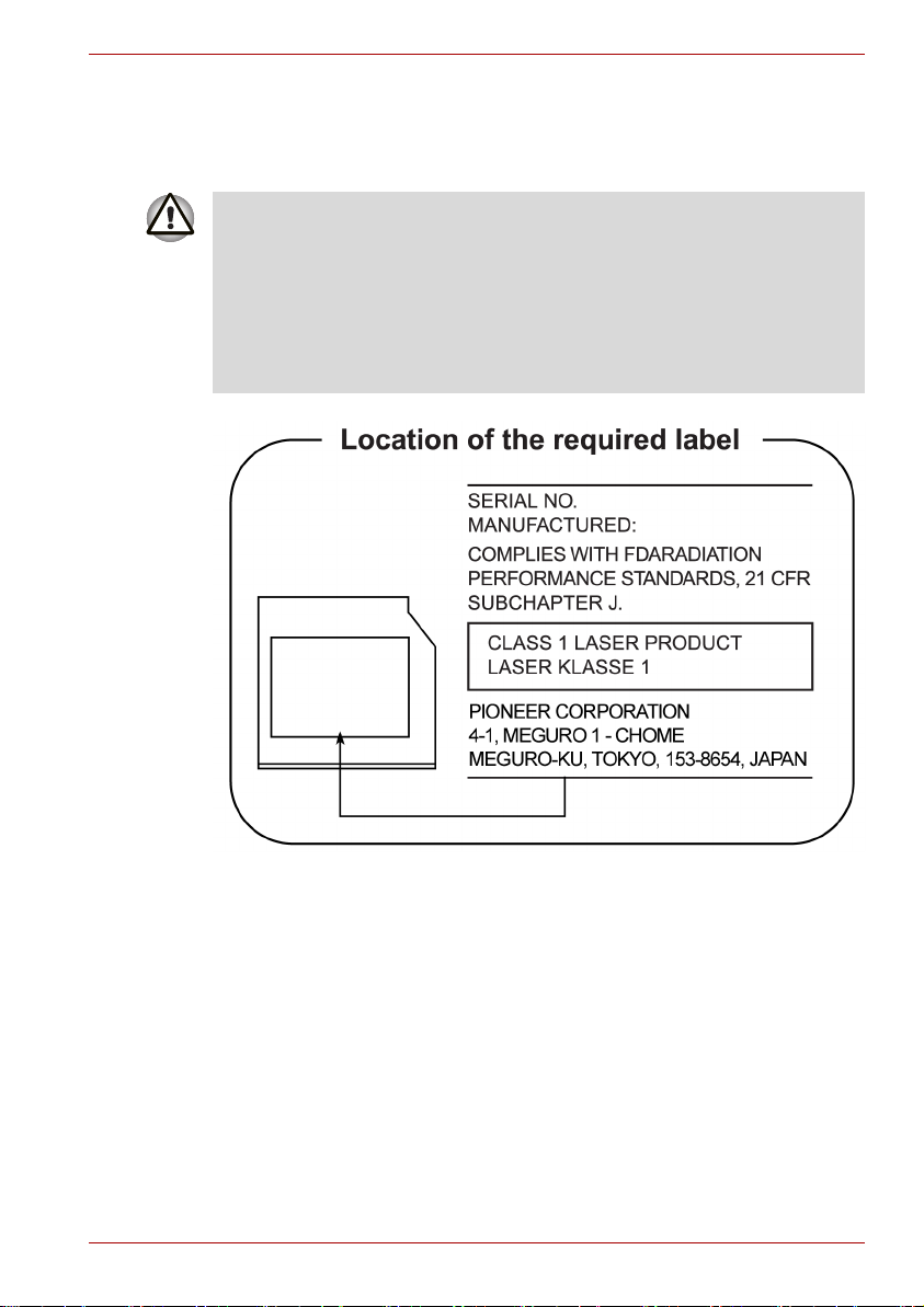
Pioneer
DVD Super Multi DVR-KD08TBF/DVR-KD08TBM
■ The DVD Super Multi drive employs a laser system. To ensure proper
use of this product, please read this instruction manual carefully and
retain for future reference. Should the unit ever require maintenance,
contact an authorized service location.
■ Use of controls, adjustments or the performance of procedures other
than those specified may result in hazardous radiation exposure.
■ To prevent direct exposure to the laser beam, do not try to open the
enclosure.
P300/P300D Series
User’s Manual x
Page 11

TOSHIBA SAMSUNG STORAGE TECHNOLOGY
DVD Super Multi TS-L633P/TS-L633A
■ This DVD writable drive employ a laser system to ensure proper use of
this product, please read this instruction manual carefully and retainfor
future reference. should the unit ever require maintenance, contact an
authorized service location-see service procedure.
■ Use of controls or adjustments or the performance of procedures other
than those specified herein may result in hazardous radiation
exposure.
■ To prevent direct exposure to laser beam, do not try to open the
enclosure.
P300/P300D Series
User’s Manual xi
Page 12

International Precautions
P300/P300D Series
CAUTION: This appliance contains a laser
system and is classified as a "CLASS 1
LASER PRODUCT." To use this model
properly, read the instruction manual
carefully and keep this manual for your
future reference. In case of any trouble
with this model, please contact your
nearest "AUTHORIZED service station."
To prevent direct exposure to the laser
beam, do not try to open the enclosure.
VORSICHT: Dieses Gerät enthält ein
Laser-System und ist als
"LASERSCHUTZKLASSE 1 PRODUKT"
klassifiziert. Für den richtigen Gebrauch
dieses Modells lesen Sie bitte die
Bedienungsanleitung sorgfältig durch und
bewahren diese bitte als Referenz auf.
Falls Probleme mit diesem Modell
auftreten, benachrichtigen Sie bitte die
nächste "autorisierte Service-Vertretung".
Um einen direkten Kontakt mit dem
Laserstrahl zu vermeiden darf das Gerät
nicht geöffnet werden.
ADVARSEL: Denne mærking er anbragt
udvendigt på apparatet og indikerer, at
apparatet arbejder med laserstråler af
klasse 1, hviket betyder, at der anvendes
laserstrlier af svageste klasse, og at man
ikke på apparatets yderside kan bilve
udsat for utilladellg kraftig stråling.
APPARATET BOR KUN ÅBNES AF
FAGFOLK MED SÆRLIGT KENDSKAB
TIL APPARATER MED LASERSTRÅLER!
Indvendigt i apparatet er anbragt den her
gengivne advarselsmækning, som advarer
imod at foretage sådanne indgreb i
apparatet, at man kan komme til at udsatte
sig for laserstråling.
User’s Manual xii
Page 13

P300/P300D Series
OBS! Apparaten innehåller
laserkomponent som avger laserstråining
överstigande gränsen för laserklass 1.
VAROITUS. Suojakoteloa si saa avata.
Laite sisältää laserdiodin, joka lähetää
näkymätöntä silmilie vaarallista
lasersäteilyä.
CAUTION: USE OF CONTROLS OR
ADJUSTMENTS OR PERFORMANCE OF
PROCEDURES OTHER THAN THOSE
SPECIFIED IN THE OWNER’S MANUAL
MAY RESULT IN HAZARDOUS
RADIATION EXPOSURE.
VORSICHT: DIE VERWENDUNG VON
ANDEREN STEUERUNGEN ODER
EINSTELLUNGEN ODER DAS
DURCHFÜHREN VON ANDEREN
VORGÄNGEN ALS IN DER
BEDIENUNGSANLEITUNG
BESCHRIEBEN KÖNNEN
GEFÄHRLICHE
STRAHLENEXPOSITIONEN ZUR FOLGE
HABEN.
Important Notice
Copyrighted works including, but not limited to music, video, computer
program, databases are protected by copyright laws. Unless specifically
permitted under applicable copyright laws, you cannot copy, modify, assign,
transmit or otherwise dispose of any copyrighted work with the consent of
the owner of the copyright. Please take notice that unauthorized copying,
modification, assignment, transmission and disposition may be subject to
claims for damages and penalties.
■ Avoid using a telephone (other than a cordless type) during an electrical
storm. There may be a remote risk of electric shock from lightning.
■ Do not use the telephone to report a gas leak in the vicinity of the leak.
■ Use only the power cord indicated in this manual.
■ Replace only with the same or equivalent type battery recommended by
the manufacturer.
■ Dispose of used batteries according to the manufacturer's instructions.
Use only the battery pack that came with the computer or an optional
battery pack. Use of wrong battery could damage your computer.
TOSHIBA assumes no liability for any damage in such case.
User’s Manual xiii
Page 14

General Precautions
TOSHIBA computers are designed to optimize safety, minimize strain and
withstand the rigors of portability. However, certain precautions should be
observed to further reduce the risk of personal injury or damage to the
computer.
Be certain to read the general precautions below and to note the cautions
included in the text of the manual.
Creating a computer-friendly environment
Place the computer on a flat surface that is large enough for the computer
and any other items you are using, such as a printer.
Leave enough space around the computer and other equipment to provide
adequate ventilation. Otherwise, they may overheat.
To keep your computer in prime operating condition, protect your work area
from:
■ Dust, moisture, and direct sunlight.
■ Equipment that generates a strong electromagnetic field, such as
stereo speakers (other than speakers that are connected to the
computer) or speakerphones.
■ Rapid changes in temperature or humidity and sources of temperature
change such as air conditioner vents or heaters.
■ Extreme heat, cold, or humidity.
■ Liquids and corrosive chemicals.
P300/P300D Series
Stress injury
Carefully read the Instruction Manual for Safety and Comfort. It contains
information on the prevention of stress injuries to your hands and wrists
that can be caused by extensive keyboard use. Chapter 3, Getting Started,
also includes information on work space design, posture and lighting that
can help reduce physical stress.
User’s Manual xiv
Page 15

Heat injury
■ Avoid prolonged physical contact with the computer. If the computer is
used for long periods, its surface can become very warm. While the
temperature will not feel hot to the touch, if you maintain physical
contact with the computer for a long time, for example if you rest the
computer on your lap or if you keep your hands on the palm rest, your
skin might suffer a low-heat injury.
■ If the computer has been used for a long time, avoid direct contact with
the metal plate supporting the various interface ports as this can
become hot.
■ The surface of the AC adaptor can become hot when in use but this
condition does not indicate a malfunction. If you need to transport the
AC adaptor, you should disconnect it and let it cool before moving it.
■ Do not lay the AC adaptor on a material that is sensitive to heat as the
material could become damaged.
Pressure or impact damage
Do not apply heavy pressure to the computer or subject it to any form of
strong impact as this can damage the computer's components or otherwise
cause it to malfunction.
ExpressCard overheating
Some PC and ExpressCards can become hot during prolonged use which
may result in errors or instability in the operation of the device in question.
In addition, you should also be careful when you remove a PC or
ExpressCard that has been used for a long time.
P300/P300D Series
Mobile phones
Please be aware that the use of mobile phones can interfere with the audio
system. The operation of the computer will not be impaired in any way, but
it is recommended that a minimum distance of 30cm is maintained between
the computer and a mobile phone that is in use.
Instruction Manual for Safety and Comfort
All important information on the safe and proper use of this computer is
described in the enclosed Instruction Manual for Safety and Comfort. Be
sure to read it before using the computer.
User’s Manual xv
Page 16

Table of Contents
Chapter 1 Introduction
Equipment checklist. . . . . . . . . . . . . . . . . . . . . . . . . . . . . . . . . . . . . . . 1-1
Features. . . . . . . . . . . . . . . . . . . . . . . . . . . . . . . . . . . . . . . . . . . . . . . . . 1-2
Special features . . . . . . . . . . . . . . . . . . . . . . . . . . . . . . . . . . . . . . . . . 1-10
TOSHIBA Value Added Package . . . . . . . . . . . . . . . . . . . . . . . . . . . . 1-11
Utilities and Applications. . . . . . . . . . . . . . . . . . . . . . . . . . . . . . . . . . 1-12
Options . . . . . . . . . . . . . . . . . . . . . . . . . . . . . . . . . . . . . . . . . . . . . . . . 1-15
Chapter 2 The Grand Tour
Front with the display closed . . . . . . . . . . . . . . . . . . . . . . . . . . . . . . . 2-1
Left side. . . . . . . . . . . . . . . . . . . . . . . . . . . . . . . . . . . . . . . . . . . . . . . . . 2-3
Right side . . . . . . . . . . . . . . . . . . . . . . . . . . . . . . . . . . . . . . . . . . . . . . . 2-4
Backside . . . . . . . . . . . . . . . . . . . . . . . . . . . . . . . . . . . . . . . . . . . . . . . . 2-5
Underside . . . . . . . . . . . . . . . . . . . . . . . . . . . . . . . . . . . . . . . . . . . . . . . 2-6
Front with the display open. . . . . . . . . . . . . . . . . . . . . . . . . . . . . . . . . 2-7
Optical Disc Drive. . . . . . . . . . . . . . . . . . . . . . . . . . . . . . . . . . . . . . . . . 2-9
AC adaptor . . . . . . . . . . . . . . . . . . . . . . . . . . . . . . . . . . . . . . . . . . . . . 2-10
Remote controller (Provided with some models) . . . . . . . . . . . . . . 2-12
P300/P300D Series
Chapter 3 Getting Started
Installing the battery pack . . . . . . . . . . . . . . . . . . . . . . . . . . . . . . . . . . 3-1
Connecting the AC adaptor . . . . . . . . . . . . . . . . . . . . . . . . . . . . . . . . . 3-2
Opening the display . . . . . . . . . . . . . . . . . . . . . . . . . . . . . . . . . . . . . . . 3-4
Turning on the power . . . . . . . . . . . . . . . . . . . . . . . . . . . . . . . . . . . . . . 3-4
Windows Vista™ setup . . . . . . . . . . . . . . . . . . . . . . . . . . . . . . . . . . . . 3-5
Turning off the power . . . . . . . . . . . . . . . . . . . . . . . . . . . . . . . . . . . . . . 3-5
Restarting the computer . . . . . . . . . . . . . . . . . . . . . . . . . . . . . . . . . . . 3-8
System Recovery Options and Restoring
the pre-installed Software . . . . . . . . . . . . . . . . . . . . . . . . . . . . . . . . . . 3-9
Restoring the pre-installed Software . . . . . . . . . . . . . . . . . . . . . . . . . 3-9
User’s Manual xvi
Page 17

P300/P300D Series
Chapter 4
Operating Basics
Using the TouchPad . . . . . . . . . . . . . . . . . . . . . . . . . . . . . . . . . . . . . . . 4-1
Using the fingerprint sensor (FingerPrint sensor
is provided with some models) . . . . . . . . . . . . . . . . . . . . . . . . . . . . . . 4-2
USB Sleep and Charge function . . . . . . . . . . . . . . . . . . . . . . . . . . . . . 4-8
Using the Web Camera. . . . . . . . . . . . . . . . . . . . . . . . . . . . . . . . . . . . 4-10
Using the microphone . . . . . . . . . . . . . . . . . . . . . . . . . . . . . . . . . . . . 4-11
Using the TOSHIBA Face Recognition . . . . . . . . . . . . . . . . . . . . . . . 4-12
Using the optical disc drive. . . . . . . . . . . . . . . . . . . . . . . . . . . . . . . . 4-15
Writing CD/DVD with the DVD Super Multi drive . . . . . . . . . . . . . . . 4-20
TOSHIBA Disc Creator . . . . . . . . . . . . . . . . . . . . . . . . . . . . . . . . . . . . 4-23
Data Verification . . . . . . . . . . . . . . . . . . . . . . . . . . . . . . . . . . . . . . . . . 4-24
Video . . . . . . . . . . . . . . . . . . . . . . . . . . . . . . . . . . . . . . . . . . . . . . . . . . 4-24
When using Ulead DVD MovieFactory® for TOSHIBA . . . . . . . . . . 4-24
Media care . . . . . . . . . . . . . . . . . . . . . . . . . . . . . . . . . . . . . . . . . . . . . . 4-26
Modem . . . . . . . . . . . . . . . . . . . . . . . . . . . . . . . . . . . . . . . . . . . . . . . . . 4-27
Using the FM tuner . . . . . . . . . . . . . . . . . . . . . . . . . . . . . . . . . . . . . . . 4-30
Wireless communications . . . . . . . . . . . . . . . . . . . . . . . . . . . . . . . . . 4-30
LAN . . . . . . . . . . . . . . . . . . . . . . . . . . . . . . . . . . . . . . . . . . . . . . . . . . . 4-33
Cleaning the computer. . . . . . . . . . . . . . . . . . . . . . . . . . . . . . . . . . . . 4-34
Moving the computer . . . . . . . . . . . . . . . . . . . . . . . . . . . . . . . . . . . . . 4-34
Chapter 5 The Keyboard
Typewriter keys. . . . . . . . . . . . . . . . . . . . . . . . . . . . . . . . . . . . . . . . . . . 5-1
F1 ... F12 function keys . . . . . . . . . . . . . . . . . . . . . . . . . . . . . . . . . . . . 5-2
Soft keys: Fn key combinations . . . . . . . . . . . . . . . . . . . . . . . . . . . . . 5-2
Hot keys. . . . . . . . . . . . . . . . . . . . . . . . . . . . . . . . . . . . . . . . . . . . . . . . . 5-2
Windows® special keys. . . . . . . . . . . . . . . . . . . . . . . . . . . . . . . . . . . . 5-4
Generating ASCII characters. . . . . . . . . . . . . . . . . . . . . . . . . . . . . . . . 5-4
Chapter 6 Power and Power-Up Modes
Power conditions . . . . . . . . . . . . . . . . . . . . . . . . . . . . . . . . . . . . . . . . . 6-1
Power indicators. . . . . . . . . . . . . . . . . . . . . . . . . . . . . . . . . . . . . . . . . . 6-2
Battery types. . . . . . . . . . . . . . . . . . . . . . . . . . . . . . . . . . . . . . . . . . . . . 6-3
Care and use of the battery pack . . . . . . . . . . . . . . . . . . . . . . . . . . . . 6-4
Replacing the battery pack . . . . . . . . . . . . . . . . . . . . . . . . . . . . . . . . 6-10
Starting the computer by password . . . . . . . . . . . . . . . . . . . . . . . . . 6-12
Power-up modes. . . . . . . . . . . . . . . . . . . . . . . . . . . . . . . . . . . . . . . . . 6-12
Panel power off/on . . . . . . . . . . . . . . . . . . . . . . . . . . . . . . . . . . . . . . . 6-13
System Auto Off . . . . . . . . . . . . . . . . . . . . . . . . . . . . . . . . . . . . . . . . . 6-13
Chapter 7 HW Setup
Accessing HW Setup . . . . . . . . . . . . . . . . . . . . . . . . . . . . . . . . . . . . . . 7-1
HW Setup Window . . . . . . . . . . . . . . . . . . . . . . . . . . . . . . . . . . . . . . . . 7-1
User’s Manual xvii
Page 18

P300/P300D Series
Chapter 8
Optional Devices
ExpressCard . . . . . . . . . . . . . . . . . . . . . . . . . . . . . . . . . . . . . . . . . . . . . 8-1
SD/SDHC/MMC/MEMORY STICK/
MEMORY STICK PRO/xD Memory cards . . . . . . . . . . . . . . . . . . . . . . 8-3
Memory expansion . . . . . . . . . . . . . . . . . . . . . . . . . . . . . . . . . . . . . . . . 8-6
Additional battery pack . . . . . . . . . . . . . . . . . . . . . . . . . . . . . . . . . . . . 8-9
Additional AC adaptor . . . . . . . . . . . . . . . . . . . . . . . . . . . . . . . . . . . . . 8-9
External monitor . . . . . . . . . . . . . . . . . . . . . . . . . . . . . . . . . . . . . . . . . . 8-9
Television . . . . . . . . . . . . . . . . . . . . . . . . . . . . . . . . . . . . . . . . . . . . . . 8-10
HDMI (optional) . . . . . . . . . . . . . . . . . . . . . . . . . . . . . . . . . . . . . . . . . . 8-11
i.LINK (IEEE1394) . . . . . . . . . . . . . . . . . . . . . . . . . . . . . . . . . . . . . . . . 8-12
eSATA (External Serial ATA) . . . . . . . . . . . . . . . . . . . . . . . . . . . . . . . 8-14
Security lock . . . . . . . . . . . . . . . . . . . . . . . . . . . . . . . . . . . . . . . . . . . . 8-15
Chapter 9 Troubleshooting
Problem solving process. . . . . . . . . . . . . . . . . . . . . . . . . . . . . . . . . . . 9-1
Hardware and system checklist . . . . . . . . . . . . . . . . . . . . . . . . . . . . . 9-3
TOSHIBA support . . . . . . . . . . . . . . . . . . . . . . . . . . . . . . . . . . . . . . . . 9-17
Appendix A Specifications
Appendix B Display Controller
Appendix C Wireless LAN
Appendix D AC Power Cord and Connectors
Appendix E Legal Footnotes
Appendix F If your computer is stolen
Glossary
Index
User’s Manual xviii
Page 19

Preface
Congratulations on your purchase of the P300/P300D Series computer.
This powerful notebook computer provides excellent expansion capability,
including multimedia devices, and it is designed to provide years of reliable,
high-performance computing.
This manual tells you how to set up and begin using your P300/P300D
Series computer. It also provides detailed information on configuring your
computer, basic operations and care, using optional devices and
troubleshooting.
If you are a new user of computers or if you’re new to portable computing,
first read over the Introduction and The Grand Tour chapters to familiarize
yourself with the computer's features, components and accessory devices.
Then read Getting Started for step-by-step instructions on setting up your
computer.
If you are an experienced computer user, please continue reading the
preface to learn how this manual is organized, then become acquainted
with this manual by browsing through its pages. Be sure to look over the
Specifications section of the Introduction, to learn about features that are
uncommon or unique to the computer. If you are going to install
ExpressCards or connect external devices such as a monitor, be sure to
read Chapter 8, Optional Devices.
P300/P300D Series
Manual contents
This manual is composed of the following nine chapters, six appendixes, a
glossary and an index.
Chapter 1, Introduction, is an overview of the computer's features,
capabilities, and options.
Chapter 2, The Grand Tour, identifies the components of the computer and
briefly explains how they function.
Chapter 3, Getting Started, provides a quick overview of how to begin
operating your computer and gives tips on safety and designing your work
area.
Chapter 4, Operating Basics, includes instructions on using the following
devices: TouchPad, Sound System, optical media drives, modem, wireless
communication and LAN. It also provides tips on care of the computer, and
CD/DVDs.
User’s Manual xix
Page 20

Chapter 5, The Keyboard, describes special keyboard functions including
hot keys.
Chapter 6, Power and Power-Up Modes, gives details on the computer's
power resources and battery save modes.
Chapter 7, HW Setup explains how to configure the computer using the
HW Setup program.
Chapter 8, Optional Devices, describes the optional hardware available.
Chapter 9, Troubleshooting, provides helpful information on how to perform
some diagnostic tests, and suggests courses of action if the computer
doesn’t seem to be working properly.
The Appendices provide technical information about your computer.
The Glossary defines general computer terminology and includes a list of
acronyms used in the text.
The Index quickly directs you to the information contained in this manual.
Conventions
This manual uses the following formats to describe, identify, and highlight
terms and operating procedures.
Abbreviations
On first appearance, and whenever necessary for clarity, abbreviations are
enclosed in parenthesis following their definition. For example: Read Only
Memory (ROM). Acronyms are also defined in the Glossary.
P300/P300D Series
Icons
Icons identify ports, dials, and other parts of your computer. The indicator
panel also uses icons to identify the components it is providing information
on.
Keys
The keyboard keys are used in the text to describe many computer
operations. A distinctive typeface identifies the key top symbols as they
appear on the keyboard. For example, Enter identifies the Enter key.
Key operation
Some operations require you to simultaneously use two or more keys. We
identify such operations by the key top symbols separated by a plus sign
(+). For example, Ctrl + C means you must hold down Ctrl and at the same
time press C. If three keys are used, hold down the first two and at the
same time press the third.
User’s Manual xx
Page 21

P300/P300D Series
ABC When procedures require an action such as
clicking an icon or entering text, the icon’s name
or the text you are to type in is represented in the
type face you see to the left.
Display
ABC
Names of windows or icons or text generated by
the computer that appears on its display screen is
presented in the type face you see to the left.
Messages
Messages are used in this manual to bring important information to your
attention. Each type of message is identified as shown below.
Pay attention! A caution informs you that improper use of equipment or
failure to follow instructions may cause data loss or damage your
equipment.
Please read. A note is a hint or advice that helps you make best use of
your equipment.
Indicates a potentially hazardous situation, which could result in death or
serious injury, if you do not follow instructions.
Terminology
This term is defined in this document as follows:
Start The word "Start" refers to the button in
Microsoft
®
Windows Vista™.
User’s Manual xxi
Page 22

Introduction
This chapter provides an equipment checklist, and it identifies the
computer's features, options and accessories.
Some of the features described in this manual may not function properly if
you use an operating system that was not pre-installed by TOSHIBA.
Equipment checklist
Carefully unpack your computer. Save the box and packing materials for
future use.
Hardware
Check to make sure you have all the following items:
■ P300/P300D Series Portable Personal Computer
■ Universal AC adaptor and power cord
■ Modular cable for modem (provided with some models)
It is necessary to install the battery to use this computer. Refer to Installing
the battery pack section in Chapter 3, Getting Started.
Introduction
Chapter 1
Software
Microsoft® Windows Vista™
The following software is preinstalled:
■ Microsoft
■ Microsoft Internet Explorer
■ TOSHIBA Value Added Package
■ TOSHIBA Hardware Setup
■ TOSHIBA Supervisor Password
■ TOSHIBA Assist
■ TOSHIBA ConfigFree
■ TOSHIBA DVD PLAYER*
User’s Manual 1-1
®
Windows Vista™
Page 23

Features
Introduction
■ TOSHIBA FingerPrint Utility *
■ TOSHIBA SD Memory Utilities
■ TOSHIBA Disc Creator
■ TOSHIBA Face Recognition*
■ TOSHIBA Acoustic Silencer
■ Ulead MovieFactory
■ Presto! BizCard 5*
■ Online Manual
Other software may be preinstalled dependant on the model purchased.
* The availability of this software is dependent on the model you purchased.
®
for TOSHIBA*
Documentation
■ P300/P300D Series Personal Computer User’s Manual
■ P300/P300D Series Quickstart
■ Warranty Information
■ Instruction Manual for Safety and Comfort
If any of the items are missing or damaged, contact your dealer
immediately.
Please visit your region’s web site for the configuration details of the model
that you have purchased.
Processor
Built-in Depend on the model you purchased.
Please visit your region's website for the
configuration details of the model that you have
purchased.
Chipset Depend on the model you purchased.
Mobile Intel
or
AMD RS780MC/RS780M/RX780M Chipset
User’s Manual 1-2
®
PM45/GM45 Express Chipset
Page 24

Introduction
Memory
Slots PC2-5300 or PC2-6400 512 MB, 1024 MB,
2048 MB or 4096 MB memory modules can be
installed in the two memory slots. Maximum
system memory size and speed are depending on
the model you purchased.
Main Memory
Disclaimer
■ Your computer supports a maximum physical memory (RAM) of 4 GB.
If your configuration has two 2 GB memory modules, only
approximately 3 GB will be reported. This is not a wrong display, but a
technical limitation of chipset, CPU and BIOS.
■ In addition, a 32-bit operating system can not address more than 4 GB
of memory.
■ The reason is that various system resources (like Flash, APIC, PCI
devices, GPU) require their own address space within the available
4 GB limit. In case of 4 GB of physical memory the address space used
by the system resources overlaps the physical memory.
■ The operating system has not the possibility to use the memory in the
overlapped address range. This reduces the addressable memory
space available to the operating system. Because Windows only
displays the available memory instead of the computer’s physical
memory, you will only see approximately 3 GB.
Part of the main system memory may be used by
the graphics system for graphics performance
and therefore reduce the amount of main system
memory available for other computing activities.
The amount of main system memory allocated to
support graphics may vary depending on the
graphics system, applications utilized, system
memory size and other factors. For PC's
configured with 4 GB of system memory, the full
system memory space for computing activities will
be considerably less and will vary by model and
system configuration.
User’s Manual 1-3
Page 25

Introduction
Video RAM Depending on the model you purchased.
Intel® GMA HD4500 model:
Video RAM capacity shares with main memory,
and the proportion depends on Dynamic Video
Memory Technology.
ATI Radeon™ HD 3200 Graphics model:
ATI Radeon™ 3100 Graphics model:
Video RAM capacity shares with main memory,
and the proportion depends on ATI
HyperMemory™.
ATI Mobility Radeon™ HD 3470 model:
External 64/128/256 MB.
ATI Mobility Radeon™ HD 3650 model:
External 256/512 MB.
Power
Battery Pack Your computer is powered by a rechargeable
lithium-ion battery pack.
RTC Battery The internal RTC battery backs up the Real Time
Clock and calendar.
AC Adaptor The universal AC adaptor provides power to the
system and recharges the batteries when they
are low. It comes with a detachable power cord.
Because it is universal, it can receive a range of
AC voltage from 100 to 240 volts; however, the
output current varies among different models.
Using the wrong model can damage your
computer. Refer to the AC adaptor section in
Chapter 2, The Grand Tour.
User’s Manual 1-4
Page 26

Disks
Introduction
Hard disk Disclaimer
1 Gigabyte (GB) means 109 = 1,000,000,000 bytes
using powers of 10. The computer operating
system, however, reports storage capacity using
powers of 2 for the definition of 1 GB = 2
30
=
1,073,741,824 bytes, and therefore shows less
storage capacity. Available storage capacity will
also be less if the product includes one or more
pre-installed operating systems, such as Microsoft
Operating System and/or pre-installed software
applications, or media content. Actual formatted
capacity may vary.
Hard disk Drive Depend on the model you purchased.
■ 120 GB
■ 160 GB
■ 200 GB
■ 250 GB
■ 320 GB
■ 400 GB
■ 500 GB
Other hard disk drives may be introduced in the
future.
Computers in this series are configured with a fixed optical media drive.
The available optical media drives are described below.
User’s Manual 1-5
Page 27

Introduction
DVD Super Multi drive Some models are equipped with a full-size DVD
Super Multi drive module that lets you record data
to rewritable CD/DVDs as well as run either 12cm
(4.72") or 8cm (3.15") CD/DVDs without using an
adaptor. It reads DVD-ROM's at maximum
8 speed and CD-ROM's at maximum 24 speed. It
writes CD-R's at up to 24 speed, CD-RW's at up
to 16 speed, DVD-R's at maximum 8 speed,
DVD-RW's at maximum 6 speed. DVD+R's at
maximum 8 speed, DVD+RW's at maximum
8 speed, DVD+R(DL) discs at maximum 6 speed
and DVD-R(DL) discs at maximun 4 speed and
DVD-RAM discs at maximum 5 speed. It supports
the following formats:
■ DVD-ROM
■ DVD-Video
■ DVD-R
■ DVD-RW
■ DVD+R
■ DVD+RW
■ DVD-RAM
■ DVD+R DL
■ DVD-R DL
■ CD-DA
■ CD-Text
■ Photo CD (single/multi-session)
■ CD-ROM Mode 1, Mode 2
■ CD-ROMXA Mode 2 (Form1, Form2)
■ Enhanced CD (CD-EXTRA)
■ CD-G (Audio CD only)
■ Addressing Method 2
Display
The computer's LCD panel supports high-resolution video graphics. The
screen can be set at a wide range of viewing angles for maximum comfort
and readability.
Built-In Thin-film transistor color LCD is available in two
sizes:
■ 17" WXGA+, 1440 horizontal × 900 vertical
pixels
User’s Manual 1-6
Page 28

Introduction
Graphics Controller Graphics controller maximizes display
performance. Refer to Display Controller section
in Appendix B, Display Controller for more
information.
Keyboard
Built-In TOSHIBA Vista keyboard, 104 keys or 105 keys
with numeric keypad, compatible with IBM
enhanced keyboard, dedicated cursor control,
and keys. Refer to Chapter 5, The
Keyboard, for details.
Pointing Device
Built-In TouchPad A TouchPad and control buttons in the palm rest
enable control of the on-screen pointer and
scrolling of windows.
Ports
External Monitor This 15-pin port lets you connect an external
HDMI This HDMI jack allows you to connect external
Universal Serial Bus
(USB 2.0)
eSATA/USB combo
port
i.LINK (IEEE1394a) This port enables high-speed data transfer
TV Out The 4-pin S-Video port is compatible with PAL or
Infrared receiver
window
video display.
display/audio devices. (Provided with some
models)
The computer has Universal Serial Bus ports that
comply with the USB 2.0 standard, which enables
data transfer speeds 40 times faster than the
USB 1.1 standard. (The ports also support
USB 1.1.)
eSATA/USB combo port port supports the
USB 2.0 and the eSATA function.
directly from external devices such as digital
video cameras.
NTSC TV standard, supporting Macrovision 7.02
copy protection. (depends on the model you
purchased)
This window receives signals from the remote
control which is provided with your computer.
(depends on the model you purchased)
User’s Manual 1-7
Page 29

Slots
Introduction
ExpressCard The ExpressCard expansion slot that can
Multiple Digital Media
Card Slot
accommodate two standard module formats; an
ExpressCard/34 module and an ExpressCard/54
module. An ExpressCard module is a small addin card technology based on the PCI Express and
Universal Serial Bus (USB) interfaces.
Supports SD/SDHC memory card, MMC,
MEMORY STICK, MEMORY STICK PRO and xD
Picture card.
Multimedia
Web Camera Record/Send still or video images with this
integrated webcam. (provided with some models)
Sound System A Windows
Headphone(S/P DIF)
jack
Microphone Jack A 3.5 mm mini microphone jack enables
speakers as well as jacks for an external
microphone and headphones.
This jack outputs analog audio signals. This jack
can be used also as S/P DIF jack and enables
connection of optical digital correspondence
apparatus.
connection of a three-conductor mini jack for
monaural microphone input.
®
Sound System that provides
Communications
Modem Where present, it provides capability for data and
LAN The computer is equipped with a LAN card that
User’s Manual 1-8
fax communication. It supports V.90 (V.92). The
speed of data transfer and fax communication
depends on the analog telephone line conditions.
The computer has a modem jack for connection
to a telephone line. Both V.90 and V.92 are
supported only in the USA, Canada, Australia.
V.90 is available in other regions. (Provided with
some models)
supports Fast Ethernet LAN (100 Mbit/s,
100 BASE-TX) or Gigabit Ethernet LAN (1 Gbit/s,
1000 BASE-T). It is preinstalled as a standard
device in some markets. (depending on model
you purchased)
Page 30

Introduction
Wireless LAN Where present, it supports the A,B,G and draft N
standards but it is compatible with other LAN
systems based on Direct Sequence Spread
Spectrum/Orthogonal Frequency Division
Multiplexing radio technology that complies with
the IEEE 802.11 Standard.
■ Automatic Transmit Rate Select mechanism in
the transmit range of 54, 48, 36, 24, 18, 12,
9 and 6 Mbit/s. (IEEE 802.11a/g)
■ Automatic Transmit Rate Select mechanism in
the transmit range of 11, 5.5, 2 and 1 Mbit/s.
(IEEE 802.11b)
■ Roaming over multiple channels
■ Card Power Management
■ Wired Equivalent Privacy (WEP) data
encryption, based on 128 bit encryption
algorithm.
■ Advanced Encryption Standard (AES) data
encryption, based on 128 bit encryption
algorithm.
Bluetooth Some computers in this series are equipped with
Bluetooth functions. Bluetooth wireless
technology eliminates the need for cables
between electronic devices such as computers
and printers. Bluetooth provides fast, reliable, and
secure wireless communication in a small space.
(Provided with some models)
Wireless
Communication
This switch turns the Wireless LAN and Bluetooth
function on and off. (Provided with some models)
Switch
Security
Security lock slot Connects an optional security lock to anchor the
computer to a desk or other large object.
Password Power-on password protection
HDD password protection
Two level password architecture
Fingerprint authentication (not available on all
models)
User’s Manual 1-9
Page 31

Special features
The following features are either unique to TOSHIBA computers or are
advanced features, which make the computer more convenient to use.
Hot Keys Key combinations let you quickly modify the
Instant Security The hot key function Fn + F1 blanks the screen
Display Automatic
Power Off
HDD Automatic Power
*1
Off
System Automatic
Sleep Mode/
Hibernation
Intelligent Power
Supply
Battery Save Mode
Panel Power On/Off
Low Battery
Automatic
Hibernation
*1
Introduction
system configuration directly from the keyboard
without running a system configuration program.
and disables the computer, providing data
security.
*1
This feature automatically cuts off power to the
internal display when there is no keyboard input
for a specified time. Power is restored when any
key is pressed.
This can be specified in the Power Options.
This feature automatically cuts off power to the
hard disc drive when it is not accessed for a
specified time. Power is restored when the hard
disc is accessed.
This can be specified in the Power Options.
This feature automatically shuts down the system
*1
into Sleep Mode or Hibernation Mode when there
is no input or hardware access for a specified
time.
This can be specified in the Power Options.
A microprocessor in the computer's intelligent
power supply detects the battery’s charge and
calculates the remaining battery capacity. It also
protects electronic components from abnormal
conditions, such as voltage overload from an
AC adaptor.
This can be specified in the Power Options.
*1
This feature lets you save battery power.
This can be specified in the Power Options.
*1
This feature turns power to the computer off when
the display panel is closed and turns it back on
when the panel is opened.
This can be specified in the Power Options.
When battery power is exhausted to the point that
*1
computer operation cannot be continued, the
system automatically enters Hibernation Mode
and shuts down.
This can be specified in the Power Options.
User’s Manual 1-10
Page 32

Introduction
Hibernation This feature lets you turn off the power without
Sleep Mode If you have to interrupt your work, you can turn off
*1 Click , Control Panel, System and Maintenance, and then click
Power Options.
exiting from your software. The contents of main
memory are saved to the hard disk so that when
you turn on the power again, you can continue
working right where you left off. Refer to the
Turning off the power section in Chapter 3,
Getting Started,for details.
the power without exiting from your software.
Data is maintained in the computer's main
memory so that when you turn on the power
again, you can continue working right where you
left off.
TOSHIBA Value Added Package
This section describes the TOSHIBA Component features pre-installed on
the computer.
TOSHIBA Power
Saver
TOSHIBA Zooming
Utility
TOSHIBA PC
Diagnostic Tool
TOSHIBA Flash Cards This utility supports the following functions.
TOSHIBA
Components
Common Driver
TOSHIBA Power Saver provides you with the
features of more various power supply
managements.
This utility allows you to enlarge or reduce the
icon size on the Windows Desktop, or the zoom
factor associated with specific supported
applications.
The TOSHIBA PC Diagnostic Tool will display
basic system configuration information and allow
the functionality of some of the computer's built-in
hardware devices to be tested.
■ Hot key function
■ TOSHIBA utility launcher function
TOSHIBA Components Common Driver contains
the module required for the utility which TOSHIBA
offers.
User’s Manual 1-11
Page 33

Introduction
TOSHIBA
Accessibility
TOSHIBA Button
Support
Utilities and Applications
This section describes pre-installed utilities and tells how to start them. For
details on operations, refer to each utility’s online manual, help files or
readme.txt files.
TOSHIBA Assist TOSHIBA Assist is a graphical user interface that
HW Setup This program lets you customize your hardware
Power On Password Two levels of password security, supervisor and
TOSHIBA Disc
Creator
The TOSHIBA Accessibility utility provides
support to movement impaired users when they
need to use the TOSHIBA Hot-key functions. In
use, the utility allows you to make the Fn key
'sticky', that is you can press it once, release it,
and then press one of the "F" keys in order to
access its specific function. When set, the Fn key
will remain active until another key is pressed.
This utility controls the button operation of the
computer.
The starting application from the button can be
changed.
(Provided with some models)
provides easy access to help and services.
settings according to the way you work with your
computer and the peripherals you use. To start
the utility, double click the TOSHIBA Assist on
your desktop, select OPTIMIZE tab, and click
TOSHIBA Hardware Settings.
user, are available to prevent unauthorized
access to your computer.
To register a supervisor password, double click
the TOSHIBA Assist on your desktop select the
SECURE tab and start the Supervisor password
utility.
To set a user password, select the SECURE tab
on TOSHIBA Assist, then start the User
password utility. On the Password tab you can
register a user password.
You can create discs in several formats including
audio CDs that can be played on a standard
stereo CD player and data discs to store the files
and folders on your hard disk drive. This software
can be used on a model with a CD-RW/
DVD-ROM drive, DVD Super Multi drive.
User’s Manual 1-12
Page 34

Introduction
TOSHIBA DVD-RAM
Utility
TOSHIBA DVD-RAM Utility has a Physical
Format function and Write-Protect function to
DVD-RAM.
This utility is contained in the TOSHIBA Disc
Creator setup module.
To run TOSHIBA DVD-RAM Utility, click ,
select All Programs, TOSHIBA, CD&DVD
Applications, and then click DVD-RAM Utility.
CD/DVD Drive
Acoustic Silencer
This utility allows you to configure the read speed
of the CD drive. You can either configure Normal
Mode, which operates the drive at its maximum
speed for quick data access, or Quiet Mode,
whcih runs at single speed for CD audio and
which can lessen operational noise. It is
ineffective in DVD mode.
Ulead DVD
MovieFactory
®
for
You can edit digital video and make a DVD-Video.
(Provided with some models)
TOSHIBA
*1 Click , Control Panel, System and Maintenance, and then click
Power Options.
FingerPrint utility This product has a fingerprint utility installed for
the purpose of enrolling and recognizing
fingerprints. (depending on the model purchased.)
By enrolling the ID and password to the fingerprint
authentication device, it is no longer necessary to
input the password from the keyboard. Just by
swiping the finger against the fingerprint sensor,
the following functions will be enabled:
■ Log-on to Windows and access a security
enabled homepage through IE (Internet
Explorer).
■ Files and folders can be encrypted/decrypted
and third party access to them prevented.
■ Disable the password-protected screensaver
when returning from power-saving (Sleep)
mode.
■ System boot authentication and Single Touch
Boot feature.
■
Power on Security and Single Sign On feature.
(Provided with some models)
TOSHIBA DVD
PLAYER
The DVD PLAYER is used to play DVD Video. It
has an on-screen interface and functions.
(Provided with some models)
User’s Manual 1-13
Page 35

Introduction
TOSHIBA ConfigFree ConfigFree is a suite of utilities to allow easy
control of communication devices and network
connections. ConfigFree also allows you to find
communication problems and create profiles for
easy switching between location and
communication networks.
To run ConfigFree, click , select All Programs,
TOSHIBA, Networking and then click
ConfigFree.
TOSHIBA Face
Recognition
TOSHIBA Face Recognition uses a face
verification library to verify the face data of users
when they log in to Windows. If the verification is
successful, the user will be logged into Windows
automatically. The user can thus avoid having to
enter a password or the like, which makes the
login process easier.(Provided with some models)
Presto! BizCard 5 Presto! BizCard keeps track of names,
companies, mailing addresses, phone/fax
numbers, e-mail addresses, and more. Simply
scan your business cards and Presto! BizCard
automatically saves the data and image for each
card. Different viewing modes are available for
easy searching, editing, creating, and sorting. You
can share information with desktop organizers,
contact managers, personal information
managers (PIMs), and personal digital assistants
(PDAs). You can also print ID badges, mailing
labels, and stickers.(Provided with some models)
Windows Mobility
Center
This section describes the Windows Mobility
Center. Mobility Center is a utility for accessing
several mobile PC settings quickly in one window.
A maximum of eight tiles are prepared as the
operating system default. Two additional tiles are
also added to your Mobility Center.
Installing the "TOSHIBA Extended Tiles for
Windows Mobility Center" package will add the
following functions.
■ Lock Computer:
Lock your computer without turning it off. This
has the same function as the Lock button at
the bottom of the right pane of the start menu.
■ TOSHIBA Assist:
Open the TOSHIBA Assist if it is already
installed in your computer.
User’s Manual 1-14
Page 36

Options
Introduction
You can add a number of options to make your computer even more
powerful and convenient to use. Refer to Chapter 8 Optional Devices, for
details. The following options are available:
Memory expansion Two memory modules can be installed in this
computer.
Use only PC2-5300 or PC2-6400* compatible DDRII memory modules.
See your TOSHIBA dealer for details.
* The availability of DDRII depends on the model you purchased.
Battery pack An additional battery pack can be purchased from
your TOSHIBA dealer. Use it as a spare to
increase your computer operating time.
AC Adaptor If you use your computer at more than one site
frequently, it may be convenient to purchase an
additional AC adaptor for each site so you will not
have to carry the adaptor with you.
User’s Manual 1-15
Page 37

The Grand Tour
This chapter identifies the various components of your computer. Become
familiar with each component before you operate the computer.
Front with the display closed
The following figure shows the computer's front with its display panel in the
closed position.
Wireless
Communication
Switch
off
DC in
LED
on
Power
LED
Battery
LED
The Grand Tour
Chapter 2
Disk
LED
Multiple Digital
Media Card Slot LED
Wireless
Activity
LED
Infrared
Receiver
Window*
Multiple
Digital Media
Card Slot
Front of the computer with display closed
Microphone
Jack
Headphone
(S/P DIF)
jack
Volu me
Dial
*Depending on the model you purchased.
Wireless
Communication
The Wireless Communication Switch turns on the
wireless networking transceiver.
Switch
Set the switch to off in airplanes and hospitals. Check the wireless activity
indicator. It will stop glowing when the wireless communication function is
off.
DC IN LED The DC IN LED indicates the computer is
connected to the AC adaptor and it is plugged into
an AC power source.
User’s Manual 2-1
Page 38

The Grand Tour
Power LED The Power indicator glows blue when the
computer is on. If you select Sleep Mode from
Turn Off Computer, this indicator flashes orange
(one second on, two seconds off) while the
computer enters Sleep Mode.
Battery LED The Battery indicator shows the condition of the
battery's charge: Blue indicates a full charge,
orange indicates that the battery is charging and
flashing orange indicates a low battery charge.
Refer to Chapter 6, Power and Power-Up Modes.
Disk LED Disk LED indicates that the hard disk drive or
optical disc drive is being accessed.
Multiple Digital Media
Card Slot LED
Multiple Digital Media Card Slot LED lights up
when the Multiple Digital Media Card Slot is
accessed. (Provided with some models)
Wireless Activity LED Indicates whether the wireless LAN or Bluetooth
is active or not. (Provided with some models)
Infrared Receiver
Window
An infrared receiver window is provided with
some models. This is a sensor window that
receives signals from the remote control which is
provided with your computer.
Multiple Digital Media
Card Slot
Supports SD/SDHC memory card, MMC,
MEMORY STICK, MEMORY STICK PRO and xD
Picture card.
Microphone Jack A 3.5 mm mini microphone jack enables
connection of a three-conductor mini jack for
monaural microphone input.
Headphone (S/P DIF)
jack
This jack outputs analog audio signals. This jack
can be used also as S/P DIF jack and enables
connection of optical digital correspondence
apparatus.
Volu m e D i a l Use this dial to adjust the volume of the stereo
speakers or headphones.
User’s Manual 2-2
Page 39

Left side
The Grand Tour
The following figure shows the computer's left side.
eSATA/
Port
Cooling VentsExternal Monitor
The left side of the computer
eSATA/USB
combo port
TV Out
Port
HDMI
port
Universal Serial
Bus (USB 2.0)
LAN
Jack
Express
Card Slot
i.LINK
(IEEE 1394a)
Port
External Monitor Port This 15-pin port lets you connect an external
video display.
Cooling Vents Cooling vents help prevent the CPU from
overheating.
Do not block the cooling vents. Also ensure that foreign objects are kept
out of the vents as items such as pins or similar objects, which can
damage the computer's circuitry.
eSATA/USB combo
port
Universal Serial Bus
(USB 2.0)
eSATA/USB combo port supports the USB 2.0
and the eSATA function.
Universal Serial Bus ports which comply to the
USB 2.0 standard, are provided. The ports with
the icon ( ) have USB Sleep and Charge
function.
ExpressCard Slot This slot allows you to insert an ExpressCard. An
ExpressCard is a small, modular add-in card
technology based on PCI Express and the
Universal Serial Bus (USB) interface. The max.
transmission rate is 2.5Gbps. ExpressCard/34
and ExpressCard/54 types are supported.
TV Out Port Connect a 4-pin S-video cable into this connector
in order to output either an NTSC or PAL
television signal.
HDMI port This port allows you to connect digitally to an
HDTV or home theater receiver.
(Provided with some models)
User’s Manual 2-3
Page 40

The Grand Tour
Right side
LAN Jack This jack lets you connect to a LAN. The adaptor
has built-in support for Fast Ethernet LAN or Giga
bit Ethernet.(Depend on the model you
purchased). Refer to Chapter 4, Operating
Basics, for details.
i.LINK (IEEE1394a)
Port
This port allows you to connect an external
device, such as a digital video camera, for
highspeed data transfer. (Provided with some
models)
The following figure shows the computer's right side.
Eject
Button
Emergency
Eject Hole
Security
DC in 19V
Jack
Lock
USB
Ports
Modem Jack or
FM Antenna
Jack*
The right side of the computer
ODD
Indicator
* The figure shows Modem Jack.
ODD Indicator The ODD indicator glows amber when the
computer accesses the optical disc drive.
Eject Button Press this button to open the ODD tray.
Security Lock A security cable attaches to this port. The optional
security cable anchors your computer to a desk or
other large object to deter theft.
Universal Serial Bus
(USB 2.0) ports
Universal Serial Bus ports which comply to the
USB 2.0 standard, are provided. The ports with
the icon ( ) have USB Sleep and Charge
function.
Modem Jack The modem jack allows you to use a modular
cable to connect the modem directly to a
telephone line. (Depends on the model you
purchased.)
■ In case of a lightning storm, unplug the
modem cable from the telephone jack.
■ Do not connect the modem to a digital
telephone line. A digital line will damage the
modem.
User’s Manual 2-4
Page 41

Backside
The Grand Tour
FM Antenna Jack A jack enables the connection of FM antenna.
(Depends on the model you purchased.)
Emergency Eject Hole In the event that the disc drive becomes
inexplicably locked or stops responding press this
button to force a manual ejection of the ODD tray.
DC IN 19V Jack The AC adaptor connects to this socket. Use only
the model of AC adaptor that comes with the
computer. Using the wrong adaptor can damage
your computer.
The following figure shows the computer's back panel.
The backside of the computer
User’s Manual 2-5
Page 42

Underside
The following figure shows the underside of the computer. Make sure the
display is closed before turning over your computer.
The Grand Tour
Cooling
Vents
Battery Pack
Lock
The underside of the computer
Memory Module
and Wireless
LAN Cover
Battery Pack
Hard Disk
Cover
Battery
Release
Latch
Cooling Vents Cooling vents help prevent the CPU from
overheating.
Memory Module and
Wireless LAN Cover
This cover protects two memory module sockets
-one or two modules are pre-installed. Refer to
the Memory expansion section in Chapter 8,
Optional Devices.
Hard Disk Cover This cover protects the hard disk.
Battery Pack Lock Slide this lock to prepare the battery pack for
removal.
Battery Pack The battery pack powers the computer when the
AC adaptor is not connected. For detailed
information on the battery pack, refer to
Chapter 6, Power and Power-Up Modes.
Battery Release Latch Slide and hold this latch to release the battery
pack for removal. For detailed information on
removing the battery pack, refer to Chapter 6,
Power and Power-Up Modes.
User’s Manual 2-6
Page 43

Front with the display open
This section shows the front of the computer with the display open. Refer to
the appropriate illustration for details. To open the display, lift the front of the
display. Position the display at a comfortable viewing angle.
Web Camera
LED*
Display
Screen
Wireless
LAN
Antenna*
Speaker
Web
Camera*
Built-in
microphone*
Power Button*
Mute Button*
CD/DVD Button*
Fingerprint Sensor*
TouchPad
Control Buttons
The Grand Tour
Play/Pause Button*
Stop Button*
Previous Button*
Next Button*
Speaker
TouchPad
The front of the computer with the display open
* Provided with some models
Please handle your computer carefully to avoid scratching or damaging the
surface.
Speakers The speakers emit sound generated by your
software as well as audio alarms, such as low
battery condition, generated by the system.
Display Screen The LCD displays high-contrast text and graphics.
Refer to Appendix B, Display Controller. When
the computer operates on the AC adaptor the
display screen’s image will be somewhat brighter
than when it operates on battery power. The lower
brightness level is intended to save battery power.
Web Camera LED Web Camera LED indicates web camera is
working or not. (Provided with some models)
Web Camera Take your picture or send your image to web
contacts. (Provided with some models)
User’s Manual 2-7
Page 44

The Grand Tour
Built-in microphone The microphone is used with the Web Camera to
talk to other Web Camera users and to record
messages on windows media.
Power Button Turns the computer on and off and puts it into
Hibernation mode and wakes it up from Sleep
mode.
Mute Button Press this button to mute/un-mute sound.
CD/DVD Button Pressing this button will launch an application
program that allows for playing of CDs or DVDs.
The application that is launched differs by model:
Windows Media Player/TOSHIBA DVD PLAYER.
Play/Pause Button Press this button to begin playing an audio CD, a
DVD movie or digital audio file. This button also
acts as a Pause button.
(Provided with some models)
Stop Button Stops playing of the CD, DVD or digital audio.
(Provided with some models)
Previous Button Skips backwards to the previous track, chapter or
digital file. Refer to Chapter 4, Operating Basics,
for details. (Provided with some models)
Next Button Skips forward to the next track, chapter or digital
file. Refer to Chapter 4, Operating Basics, for
details. (Provided with some models)
TouchPad A TouchPad located in the centre of the palm rest
is used to control the on-screen pointer.
Fingerprint Sensor Just by swiping the finger against the fingerprint
sensor, the following functions will be enabled:
Log-on to Windows and access a securityenabled homepage through IE (Internet Explorer)
Files and folders can be encrypted/decrypted and
third party access to them prevented. Disable the
password-protected screensaver when returning
from power-saving (Sleep) mode. System boot
authentication and Single Touch Boot feature.
Authentication of the User Password and Hard
Disk Drive Password when booting up the
computer. Refer to the Using the fingerprint
sensor (FingerPrint sensor is provided with some
models) section in Chapter 4, Operating Basics.
(Provided with some models)
TouchPad Control
Buttons
These let you select menu items or manipulate
text and graphics designated by the on-screen
pointer. Refer to the Using the TouchPad section
in Chapter 4, Operating Basics.
User’s Manual 2-8
Page 45

Optical Disc Drive
An ATAPI interface controller is used for optical disc operation. When the
computer is accessing an optical disc, an indicator on the drive glows.
Region codes for DVD drive and media
Optical disc drive and their associated media are manufactured according
to the specifications of six marketing regions. When you purchase
DVD-Video, make sure it matches your drive, otherwise it will not play
properly.
Code Region
1 Canada, United States
2 Japan, Europe, South Africa, Middle East
3 Southeast Asia, East Asia
4 Australia, New Zealand, Pacific Islands, Central
5 Russia, Indian Subcontinent, Africa, North Korea,
6 China
Writable discs
This section describes the types of writable CD/DVD discs. Check the
specifications of your drive for the type of discs it can write. Refer to
Chapter 4, Operating Basics.
The Grand Tour
America, South America, Caribbean
Mongolia
CDs
■ CD-R discs can be written only once. The recorded data cannot be
erased or changed.
■ CD-RW discs can be recorded more than once. Use either 1, 2, or
4 multi speed CD-RW discs or high-speed 4- to 10-speed discs. The
write speed of the ultra-speed CD-RW discs (Ultra-speed is available
on the DVD-ROM & CD-R/RW drive only) is a maximum of 24-speed.
DVDs
■ DVD-R, DVD+R, DVD-R DL and DVD+R DL discs can be written only
once. The recorded data cannot be erased or changed.
■ DVD-RW, DVD+RW and DVD-RAM discs can be recorded more than
once.
User’s Manual 2-9
Page 46

DVD Super Multi drive
The full-size DVD Super Multi drive module lets you record data to writable
CD/DVDs as well as run either 12 cm (4.72") or 8 cm (3.15") CD/DVDs
without using an adaptor.
The read speed is slower at the centre of a disc and faster at the outer
edge.
DVD read 8 speed (maximum)
DVD-R write 8 speed (maximum)
DVD-RW write 6 speed (maximum)
DVD+R write 8 speed (maximum)
DVD+RW write 8 speed (maximum)
DVD-R(DL) write 6 speed (maximum)
DVD+R(DL) write 6 speed (maximum)
DVD-RAM write 5 speed (maximum)
CD read 24 speed (maximum)
CD-R write 24 speed (maximum)
CD-RW write 16 speed (maximum, Ultra-speed media)
AC adaptor
The AC adaptor converts AC power to DC power and reduces the voltage
supplied to the computer. It can automatically adjust to any voltage from
100 to 240 volts and to a frequency of either 50 or 60 hertz, enabling you to
use the computer in almost any country/region.
To recharge the battery, simply connect the AC adaptor to a power source
and the computer. Refer to Chapter 6, Power and Power-Up Modes, for
details.
The Grand Tour
User’s Manual 2-10
Page 47
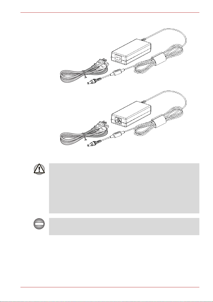
The AC adaptor
The Grand Tour
■ Use only the AC adaptor that came with the computer or an equivalent
optional adaptor. Use of the wrong adaptor could damage your
computer. TOSHIBA assumes no liability for any damage in such case.
■ Use only the AC Adaptor supplied with your computer or an equivalent
adaptor that is compatible. Use of any incompatible adaptor or other
types of AC Adaptors may have a different voltage which could cause
damage to your computer, computer failure and/or possible data loss.
TOSHIBA assumes no liability for any damage, computer failure and/or
data loss caused by use of an incompatible adaptor.
Use only the AC adaptor supplied as an accessory. Other AC adaptors
have different voltage and terminal polarities and use of them may produce
heat and smoke or even result in fire or rupture.
User’s Manual 2-11
Page 48

Remote controller (Provided with some models)
A remote controller, which is provided with some models, enables you to
perform some functions of your computer from a distant location.
You can use your remote controller with Media Center to play CDs, DVDs
and videos, to view pictures.
The remote controller helps you to control the playback of a movie through
Media Center.
Using the remote controller, you can:
■ Navigate and control all Media Center windows.
■ Control the video.
■ Place the computer in and out of Sleep mode.
Slim size remote controller
The Grand Tour
DVD Menu
Volume +
Volume -
OK
Mute
Back
Start
Rewind
Replay
CD/DVD
Button
LCD Brightness
Down
Stop
LCD
Brightness Up
Power
LED On/Off
Arrows
More Information
Fast Forward
Paly/Pause
Skip
CD/DVD button Press this button to launch an application
program that allows Windows Media Player/DVD
Video Player.
Brightness down Decreases the computer’s display panel
brightness in individual steps.
Brightness up Increases the computer’s display panel
brightness in individual steps.
User’s Manual 2-12
Page 49

The Grand Tour
Power Starts or terminate the operating system.This
button functions like the power button of your
computer. By default, the Sleep mode is
equivalent to the power off state of your computer.
To change the setting, click Start Control
panel System and Maintenance Power
Options Choose what the Power button
does. The following four options are available: Do
nothig, Sleep, Hibernate and Shut down.
Volu m e + Increases the volume while viewing DVDs or
replaying CDs.
Volu m e - Decreases the volume while viewing DVDs or
replaying CDs.
DVD menu Opens the main menu on a DVD movie, if
available.
Arrows Moves the cursor to navigate within Media Center
windows.
OK Selects the desired action or window option. It
acts like the ENTER Key.
LED on/off Pressing this button to switch the lighting of
indicators.
Mute Turns your computer sound off.
Back Displays the previous window.
More information The button provides more detail information.
Start Opens Media Center to the main window.
Rewind Moves the media (video, DVD, music, and so on)
backwards.
Play/Pause Plays the selected media. This button also acts as
a pause button.
Fast forward Moves the media (video, DVD, music, and so on)
forwards.
User’s Manual 2-13
Page 50

The Grand Tour
Replay Moves media backward (seven seconds for
Stop Stops the media currently playing.
Skip Moves media forward (30 seconds for videos, one
videos, one music track or one DVD chapter at a
time).
music track or one DVD chapter).
Using the remote controller
Some computers include a remote control unit, which allows you to control
some of your computer’s functions from a distant location.
■ The remote controller is designed specifically for this computer.
■ Some application programs may not support remote control functions.
Operational range of the remote controller
Point the remote controller at your computer and press a button. The
operational angle and distance are described below.
Distance Within 5 meters from the infrared receiver
window.
Angle Within about 30 degrees horizontally and about
15degrees vertically of perpendicular to the
infrared receiver window.
User’s Manual 2-14
Page 51

30 Degrees
15 Degrees
(Vertically)
The Grand Tour
Infrared Receiver
Window
30 Degrees
Remote Controller
Operational range of the remote controller
5M
Even if within the effective scope as described above, the remote controller
may malfunction or not work correctly in the following cases.
■ When an obstacle stands between the infrared receiver window of your
computer and the remote controller.
■ When direct sunlight or strong fluorescent light strikes the infrared
receiver window.
■ When the infrared receiver window or the infrared emission part of the
remote controller is dirty.
■ When other computers which use an infrared remote controller are
used near to your computer.
■ When a low battery condition is present.
User’s Manual 2-15
Page 52

Installing/Removing batteries
Be sure to install the provided CR2016 type batteries before using the
remote controller. The procedures for installing and removing the batteries
vary depending on the type of the remote controller. Check the type and
then install or remove the batteries as instructed.
Store the battery for the remote controller beyond the reach of children. If a
child swallows a battery, this might result in choking. If it happens, contact
a doctor immediately.
Observe the following precautions when using the battery of the remote
controller.
■ Do not use batteries other than those specified.
■ Ensure that you insert the batteries with their polarities correctly
aligned (+ or -).
■ Do not recharge, heat, disassemble or short the battery, or put it into a
fire or flame.
■ Do not use a battery whose "recommended expiration date" has been
reached, or which is completely discharged.
■ Do not use different types of batteries or old and new batteries at the
same time.
■ Do not carry the battery together with metal necklaces, hairpins or
other metal accessories.
■ When storing or disposing of used batteries, make sure to put some
insulation tape on their terminals (+ and -) to avoid short-circuits.
If these precautions are not followed, heating, fluid leakage or explosion
may occur. This may cause burns or personal injury. If battery fluid gets on
your skin or clothes, wash immediately with clean water. If battery fluid
gets in your eyes, rinse your eyes with clean water immediately and see a
doctor. Do not touch the battery fluid on instruments or devices with bare
hands. Wipe off with a cloth or paper towel.
The Grand Tour
User’s Manual 2-16
Page 53

The Grand Tour
Type of battery that can be used for the remote controller
When the provided batteries run down, please replace them with adequate
ones. CR2016 type battery is available. Other types or battery should not
be used.
Installing the batteries
1. Open the battery cover on the back side of the remote controller.
Battery Cover
Opening the battery cover
2. Be sure to place the batteries with correct polarities. Press the battery
down to the stopper then push it forward to fit into the battery case.
BatteryStopper
Inserting the batteries
3. Close the battery cover. Close the cover securely until it clicks.
Closing the battery cover
Replacing the batteries
When the batteries in the remote controller reach the end of their life, the
remote controller may not operate correctly or work only within a short
distance from your computer. In this instance, you should purchase new
batteries and replace the discharged ones.
User’s Manual 2-17
Page 54

Slim size remote controller
1. Open the battery cover on the back side of the remote controller.
2. Hold down the stopper and slide the battery out of battery case.
BatteryStopper
Removing the batteries
3. Insert the battery in place. Be sure to place the batteries with correct
polarities. Press the battery down to the stopper then push it forward to
fit into the battery case.
4. Close the battery cover. Close the cover securely until it clicks.
Placing slim size remote controller
Inserting a slim size remote controller
To insert the slim size remote controller, follow the steps below.
1. Make sure the ExpressCard slot is empty.
2. Set the front side upward and insert the slim size remote controller.
The Grand Tour
Slim size remote
controller
Inserting the slim size remote controller
3. Press gently to ensure a firm connection.
Remove a slim size remote controller
To remove the slim size remote controller, follow the steps below.
1. Press the slim size remote controller slightly to make it stretch out.
2. Grasp the slim size remote controller and pull it out from the slot.
User’s Manual 2-18
Page 55

Getting Started
This chapter provides basic information to get you started using your
computer. It covers the following topics:
Be sure also to read the Instruction Manual for Safety and Comfort. This
guide, which is included with the computer, explains product liability.
■ Installing the battery pack
■ Connecting the AC adaptor
■ Opening the display
■ Turning on the power
■ Windows Vista™ setup
■ Turning off the power
■ Restarting the computer
■ System Recovery Options
■ Restoring the preinstalled Software
All users should be sure to read the section Windows Vista setup.
Getting Started
Chapter 3
Installing the battery pack
To install a battery, follow the steps below.
■ The battery pack is a lithium ion battery, which can explode if not
properly replaced, used, handled or disposed of. Dispose of the battery
as required by local ordinances or regulations. Use only batteries
recommended by TOSHIBA as replacements.
■ Do not touch the latch while holding the computer. Or you may get
injured by the dropped battery by unintentional release of the latch.
■ Please do not push the power button before installing the battery pack.
1. Turn the computer's power off.
2. Disconnect all cables connected to the computer.
3. Insert the battery pack. The Battery Release Latch clicks into place.
User’s Manual 3-1
Page 56

Getting Started
4. Secure the Battery Pack Lock to ensure the battery is locked into place.
Later, when you want to remove the battery you must disengage this
lock first.
Battery
Pack
Lock
Refer to Removing the battery pack section in Chapter 6, Power and
Power-Up Modes,for removing the battery pack.
Connecting the AC adaptor
Attach the AC adaptor when you need to charge the battery or you want to
operate from AC power. It is also the fastest way to get started, because
the battery pack will need to be charged before you can operate from
battery power.
The AC adaptor can be connected to any power source supplying from
100 to 240 volts and 50 or 60 hertz. For details on using the AC adaptor to
charge the battery pack, refer to Chapter 6, Power and Power-Up Modes.
Use only the AC adaptor supplied as an accessory. Other AC adaptors
have different voltage and terminal polarities and use of them may produce
heat and smoke or even result in fire or rupture.
Securing the battery pack
Battery
Release
Latch
User’s Manual 3-2
Page 57

Getting Started
■ Use only the AC adaptor supplied with your computer or an equivalent
adaptor that is compatible. Use of any incompatible adaptor could
damage your computer. TOSHIBA assumes no liability for any damage
caused by use of an incompatible adaptor.
■ When you connect the AC adaptor to the computer, always follow the
steps in the exact order as described in the User's Manual. Connecting
the power cable to a live electrical outlet should be the last step
otherwise the adaptor DC output plug could hold an electrical change
and cause an electrical shock or minor bodily injury when touched. As
a general safety precaution, avoid touching any metal parts.
1. Connect the power cord to the AC adaptor.
Connecting the power cord to the AC adaptor
2. Connect the AC adaptor's DC output plug to the DC IN 19V jack on the
back of the computer.
Connecting the adaptor to the computer
3. Plug the power cord into a live wall outlet.
User’s Manual 3-3
Page 58

Opening the display
The display panel can be rotated in a wide range of angles for optimal
viewing.
1. Lift the panel up and adjust it to the best viewing angle for you.
Use reasonable care when opening and closing the display panel. Opening
it vigorously or slamming it shut could damage the computer.
Getting Started
Opening the display
Turning on the power
This section describes how to turn on the power.
After you turn on the power for the first time, do not turn it off until you have
set up the operating system. Refer to the section Windows Vista™ setup.
Press and hold the computer's power button for two or three seconds.
User’s Manual 3-4
Page 59

Windows Vista™ setup
When you first turn on the power, the computer's initial screen is the
Microsoft
Follow the on-screen directions.
Be sure to read the Windows End User License Agreement
display carefully.
®
Windows Vista™ Startup Screen Logo.
Getting Started
Turning on the power
Turning off the power
The power can be turned off in one of the following modes: Shut down
(Boot), Hibernation or Sleep Mode.
Shut Down mode (Boot mode)
When you turn off the power in Shut Down mode no data is saved and the
computer will boot to the operating system’s main screen.
1. If you have entered data, save it to the hard disk.
2. Make sure all disk (disc) activity has stopped, then remove the CD/
DVDs.
Make sure the Disk LED and ODD indicator indicators are off. If you turn
off the power while a disk (disc) is being accessed, you can lose data or
damage the disk (disc).
3. Click then click the arrow icon located in the power management
button . From the pull down menu, choose Shut Down.
4. Turn off the power to any peripheral devices.
User’s Manual 3-5
Page 60

Do not turn the computer or devices back on immediately. Wait a moment
to let all capacitors fully discharge.
Sleep Mode
If you have to interrupt your work, you can turn off the power without exiting
from your software. Data is maintained in the computer's main memory.
When you turn on the power again, you can continue working right where
you left off.
■ When the AC adaptor is connected, the computer will go into Sleep
Mode according to the settings in the Power Options.
■ To restore operation from Sleep Mode, press the power button or press
any key. The latter action works only if Wake-up on Keyboard is
enabled in HW Setup.
■ If the computer automatically enters Sleep Mode while a network
application is active, the application might not be restored when the
computer wakes up from Sleep Mode.
■ To prevent the computer from automatically entering Sleep Mode,
disable Sleep Mode in the Power Options. That action, however, will
nullify the computer's Energy Star compliance.
■ Before entering Sleep Mode, be sure to save your data.
■ Do not install or remove a memory module while the computer is in
Sleep Mode. The computer or the module could be damaged.
■ Do not remove the battery pack while the computer is in Sleep Mode
(unless the computer is connected to an AC power source). Data in
memory will be lost.
Getting Started
Benefits of Sleep Mode
The Sleep Mode feature provides the following benefits:
■ Restores the previous working environment more rapidly than does
Hibernation Mode.
■ Saves power by shutting down the system when the computer receives
no input or hardware access for the duration set by the System Sleep
Mode feature.
■ You can use the panel power off feature.
Entering Sleep Mode
You can enter Sleep Mode in one of three ways:
■ Click Start then click the power button ( ) located in the power
management buttons ( ).
Please note that this feature must be enabled within the Power Options
(to access it, click Control Panel System and
Maintenance Power Options).
User’s Manual 3-6
Page 61
■ Click , click power button located in the power management
buttons , or click arrow button and select Sleep from
the menu.
■ Close the display panel. This feature must be enabled. Please refer to
the Power Options (to access it, click Control Panel System
and Maintenance Power Options).
When you turn the power back on, you can continue where you left when
you shut down the computer.
You can also enable Sleep Mode by pressing Fn + F3. Refer to Chapter 5,
The Keyboard, for details.
■ When the computer is shut down in Sleep Mode, the power indicator
flashes orange.
■ If you are operating the computer on battery power, you can lengthen
the operating time by turning it off into Hibernation Mode, as Sleep
Mode consumes more power.
Sleep Mode limitations
Sleep Mode will not function under the following conditions:
■ Power is turned back on immediately after shutting down.
■ Memory circuits are exposed to static electricity or electrical noise.
Hibernation Mode
The hibernation feature saves the contents of memory to the hard disk
when the computer is turned off. The next time the computer is turned on,
the previous state is restored. The hibernation feature does not save the
status of peripheral devices.
■ Save your data. While entering Hibernation Mode, the computer saves
the contents of memory to the HDD. However, for safety sake, it is best
to save your data manually.
■ Data will be lost if you remove the battery or disconnect the AC adaptor
before the save is completed. Wait for the disk indicator to go out.
■ Do not install or remove a memory module while the computer is in
Hibernation Mode. Data will be lost.
Getting Started
Benefits of Hibernation Mode
The Hibernation Mode feature provides the following benefits:
■ Saves data to the hard disk when the computer automatically shuts
down because of a low battery.
■ You can return to your previous working environment immediately when
you turn on the computer.
■ Saves power by shutting down the system when the computer receives
no input or hardware access for the duration set by the System
hibernate feature.
User’s Manual 3-7
Page 62

Getting Started
■ You can use the panel power off feature.
Starting Hibernation Mode
You can also enable Hibernation Mode by pressing Fn + F4. Refer to
Chapter 5, The Keyboard, for details.
To enter Hibernation Mode, follow the steps below.
1. Click .
2. Click the arrow icon located in the power management button
3. From the pull down menu, select Hibernate.
.
Automatic Hibernation Mode
The computer will enter Hibernation mode automatically when you press
the power button or close the Display Screen. First, however, make the
appropriate settings according to the steps below.
1. Open the Control Panel.
2. Open System and Maintenance and open Power Options.
3. Select the Choose what the power button does.
4. Enable the desired Hibernation settings for When I press the power
button and When I close the lid.
5. Click the Save changes button.
Data saving in Hibernation Mode
When you turn off the power in Hibernation Mode, the computer takes a
moment to save current memory data to the hard disk. During this time, the
disk indicator will light.
After you turn off the computer and memory is saved to the hard disk, turn
off the power to any peripheral devices.
Do not turn the computer or devices back on immediately. Wait a moment
to let all capacitors fully discharge.
Restarting the computer
Certain conditions require that you reset the system. For example, if:
■ You change certain computer settings.
■ An error occurs and the computer does not respond to your keyboard
commands.
■ There are three ways to reset the computer system:
1. Click then click the arrow icon located in the power management
button , and select Restart from pull down menu.
2. Press Ctrl + Alt + Del to display the menu window, then select Restart
from the Shut down options.
User’s Manual 3-8
Page 63

Getting Started
3. Press the power button and hold it down for five seconds. Once the
computer has turned itself off, wait between ten and fifteen seconds
before turning it on again with the power button.
System Recovery Options and Restoring the pre-installed Software
System Recovery Options
About 1.5 GB hidden partition is allocated on the hard disk drive for the
System Recovery Options.
This partition stores files which can be used to repair the system in the
event of a problem.
The System Recovery Options feature will be unusable if this partition is
deleted.
System Recovery Options
The System Recovery Options feature is installed on the hard disk when
shipped from the factory. The System Recovery Options menu includes
tools to repair startup problems, run diagnostics or restore the system.
See the Windows Help and Support content for more information about
Startup Repair.
The System Recovery Options can also be run manually to repair
problems.
The procedure is as follows. Follow the instructions shown on the onscreen menu.
1. Turn off the computer.
2. Turn on the computer and when the TOSHIBA screen appears
repeatedly press the F8 key.
3. The Advanced Boot Options menu will be displayed.
Use the arrow keys to select Repair Your Computer and press
ENTER.
4. Follow the on-screen instructions.
The Windows Vista® CompletePC Backup feature can be used on
Windows Vista
®
Business Edition and Ultimate Edition.
Restoring the pre-installed Software
Depending on the model you purchased, different ways for restoring the
pre-installed software are offered:
■ Creating optical Recovery Discs
■ Restoring the pre-installed software from your created Recovery Discs.
■ Restoring the pre-installed software from the Recovery hard disk drive
User’s Manual 3-9
Page 64

Creating Optical Recovery Discs
This section describes how to create Recovery Discs.
■ Be sure to connect the AC adaptor when you create Recovery Discs.
■ Be sure to close all other software programs except the Recovery Disc
Creator.
■ Do not run software such as screen savers which can put a heavy load
on the CPU.
■ Operate the computer at full power.
■ Do not use power-saving features.
■ Do not write to the disc when the virus check software is running. Wait
for it to finish, then disable virus detection programs including any
software that checks files automatically in the background.
■ Do not use utilities, including those intended to enhance hard disk drive
access speed. They may cause unstable operation and damage data.
■ Do not shut down/log off or Sleep/Hibernate while writing or rewriting
the disc.
■ Set the computer on a level surface and avoid places subjected to
vibrations such as airplanes, trains or cars.
■ Do not place your computer on unstable tables or any other unstable
surfaces.
A recovery image of the software on your computer is stored on the hard
disk drive, and can be copied to DVD media by using the following steps:
1. Have a blank DVD media ready.
2. The application will allow you to choose from a variety of different media
onto which the recovery image can be copied including DVD-R,
DVD-RW, DVD+R, DVD+RW.
Getting Started
Please note that some of the above media may not be compatible with the
optical disc drive installed into your computer. You should therefore verify
the optical disc drive supports the blank media you have chosen before
proceeding.
3. Turn on your computer and allow it to load the Windows Vista®
operating system from the hard disk drive as normal.
4. Insert the first blank media into the optical disc drive tray.
®
5. Double click the Recovery Disc Creator icon on the Windows Vista
desktop, or select the application from Start Menu.
6. After Recovery Disc Creator starts, select the type of media and the title
you wish to copy, and then click the Create button.
7. Follow the on-screen instructions.
Your Recovery Discs will be created.
User’s Manual 3-10
Page 65

Getting Started
Restoring the pre-installed software from your created Recovery
Discs
If the pre-installed files are damaged, you are able to use the Recovery
Discs you have created to restore the computer to the state it was in when
you originally received it. To perform this restoration, follow the steps
below:
When the sound mute feature has been activated by pressing the
Fn + ESC key, be sure to disable this to allow sounds to be heard before
starting the restore process. Please refer to Chapter 5, The Keyboard for
further details.
When you reinstall the Windows operating system, the hard disk will be
reformatted and all data will be lost.
1. Load the Recovery Discs into the optical disc drive and turn off the
computer's power.
2. While holding down F12 key on the keyboard, turn on your computer when the
3. Use the cursors key to select the CD-ROM icon from the menu. Please
refer to the Boot Priority section in Chapter 7, HW Setup & BIOS Setup
for further information.
4. A menu will be displayed from which you should follow the on-screen
instructions.
TOSHIBA logo screen appears, release the F12 key.
Restoring the pre-installed software from the Recovery hard disk
drive
On your Data drive you may find a folder "HDDRecovery". This folder
stores files which can be used to recover your system to the originally
installed factory state.
If you subsequently set up your hard disk drive again, do not change,
delete or add partitions in a manner other than specified in the manual,
otherwise you may find that space for the required software is not available.
In addition, if you use a third-party partitioning program to reconfigure the
partitions on your hard disk drive, you may find that it becomes impossible
to setup your computer.
When the sound mute feature has been activated by pressing the
Fn + ESC key, be sure to disable this to allow sounds to be heard before
starting the restore process. Please refer to Chapter 5, The Keyboard, for
further details.
User’s Manual 3-11
Page 66

Getting Started
Be sure to connect the AC adaptor, otherwise you may run out of battery
during the recovery process.
When you reinstall the Windows operating system, the hard disk will be
reformatted and all data will be lost.
1. Turn off the computer.
2. Turn on the computer and when the TOSHIBA screen appears
repeatedly press the F8 key.
3. The Advanced Boot Options menu will be displayed.
Use the arrow keys to select Repair Your Computer and press
ENTER.
4. Select your preferred keyboard layout and press Next.
5. To access the recovery process please log on as an enabled user with
sufficent rights.
6. Click TOSHIBA HDD Recovery on the System Recovery Options
screen.
7. Follow the on-screen instructions on the TOSHIBA HDD Recovery
dialog.
The computer will be restored to its factory state.
Please set your BIOS to default before you recover your computer to the
factory state!
User’s Manual 3-12
Page 67

Operating Basics
This chapter gives information on basic operations including using the
TouchPad, optical media drives, sound system, modem, the wireless LAN
and LAN. It also provides tips on caring for your computer.
Using the TouchPad
To use the TouchPad, simply touch and move your finger tip across it in the
direction you want the on-screen pointer to go.
Operating Basics
Chapter 4
TouchPad
TouchPad
control buttons
TouchPad and TouchPad control buttons
Two buttons below the keyboard are used like the buttons on a mouse
pointer. Press the left button to select a menu item or to manipulate text or
graphics designated by the pointer. Press the right button to display a menu
or other function depending on the software you are using.
User’s Manual 4-1
Page 68

Operating Basics
Do not press on the TouchPad too hard or press a sharp object such as a
ball point pen against the TouchPad. The TouchPad could be damaged.
For some functions, you can tap the TouchPad instead of pressing a control
button.
Click: Tap the TouchPad once
Double-click: Tap the TouchPad twice
Drag and drop: 1. Hold down the left control button and move the
cursor to drag the item you want to move.
2. Lift your finger to drop the item where you want it.
Scroll: Vertical: Move your finger up or down the right edge
of the TouchPad.
Horizontal: Move your finger left or right along the
bottom edge of the TouchPad.
Using the fingerprint sensor
(FingerPrint sensor is
provided with some models)
This product has a fingerprint utility installed for the purpose of enrolling
and recognizing fingerprints. By enrolling the ID and password to the
fingerprint authentication device, it is no longer necessary to input the
password from the keyboard. Just by swiping the finger against the
fingerprint sensor, the following functions will be enabled:
■ Logon to Windows and access a security-enabled homepage through
IE (Internet Explorer).
■ Files and folders can be encrypted/decrypted and third party access to
them prevented.
■ Disable the password-protected screen-saver when returning from
power-saving (Sleep) mode.
■ Pre-OS feature and Single Sign-On feature.
■ Authentication of the User Password and Hard Disk Password when
booting up the computer.
To "swipe" refers to the action of reading a fingerprint using the fingerprint
sensor.
How to swipe the finger
Using the following steps when swiping fingers for fingerprint registration or
authentication will help to minimize authentication failures:
1. Align the first joint of the finger to the center of the sensor. Lightly touch
the sensor and swipe finger levelly towards you.
2. While lightly touching the sensor, swipe the finger towards you until the
sensor surface becomes visible.
3. Ensure the center of the fingerprint is on the sensor when swiping the
finger.
User’s Manual 4-2
Page 69

Operating Basics
Slide the finger over the recognition sensor
■ Avoid swiping with the finger stiff or pressed-on too hard:
Fingerprint reading may fail if the center of the fingerprint is not
touching on the sensor, or when finger is swiped while pressing hard.
Make sure that the center of the fingerprint is touching the sensor
before swiping.
■ Confirm the center of the fingerprint whirl before swiping:
The thumb’s fingerprint has a bigger whirl, which is prone to
misalignment and distortions. This will cause difficulty in registration
and a drop in the authentication success rate. Always confirm the
center of the fingerprint whirl so that it is swiped along the centerline of
the sensor.
■ When fingerprint reading is not successful:
There is a possibility of authentication failures if the finger is swiped too
quickly or too slowly. Follow the onscreen instructions to adjust the
speed of the swipe.
Points to note about the fingerprint sensor
Failure to follow these guidelines might result in (1) damage to the sensor
or cause sensor failure, (2) finger recognition problems, or lower finger recognition success rate.
■ Do not scratch or poke the sensor with your nails or any hard or sharp
objects.
■ Do not press the sensor strongly.
■ Do not touch the sensor with a wet finger or any wet objects. Keep
sensor surface dry and free of water vapor.
■ Do not touch the sensor with a soiled finger. Minute foreign particles on
a soiled or dirty finger may scratch the sensor.
■ Do not paste stickers or write on the sensor.
■ Do not touch the sensor with a finger or any object with built-up static
electricity.
Observe the following before you place your finger on the sensor whether
for fingerprint enrollment/registration or recognition.
User’s Manual 4-3
Page 70

Operating Basics
■ Wash and dry your hands thoroughly.
■ Remove static electricity from your fingers by touching any metal
surface. Static electricity is a common cause of sensor failures,
especially when the weather is dry.
■ Clean the sensor with a lint-free cloth. Do not use detergent to clean the
sensor.
■ Avoid the following finger conditions for enrollment or recognition as
they may result in fingerprint enrollment errors or a drop in the
fingerprint recognition success rate.
■ Soaked or swollen finger (e.g. after taking bath)
■ Injured finger
■ Wet finger
■ Soiled or oily finger
■ Extremely dry skin condition on finger
Observe the following to improve the fingerprint recognition success rate.
■ Enroll two or more fingers.
■ Enroll additional fingers if recognition failure occurs often using enrolled
fingers.
■ Check your finger condition. Changed conditions, such as injured,
rough, extremely dry, wet, soiled, dirty, oily, soaked, swollen fingers,
may lower the recognition success rate. Also if the fingerprint is worn
down or the finger becomes thinner or fatter, the recognition success
rate may be lowered.
■ The fingerprint for each finger is different and unique. Please ensure
that only the registered or enrolled fingerprint or fingerprints are used
for identification.
■ Check sliding position and speed.
■ Fingerprint data is enrolled up to 30~34.
■ Fingerprint data is stored into the nonvolatile memory in the fingerprint
sensor. Deleting the fingerprint data with Delete menu on Fingerprint
Software Management before you dispose the computer is
recommended.
How to delete the fingerprint data
Saved fingerprint data is stored in the Non-volatile memory inside the
fingerprint sensor. If you hand over the PC to others, or dispose of it, the
following operations are recommended.
1. Click Start, point to All Programs, point to TrueSuite Access
Manager and click it.
2. The TrueSuite Access Manager Fingerprint Software screen is
displayed.
3. Enter your Windows Password and click Next to enter the Control
Center. Or swipe your enrolled finger to enter the Control Center.
4. Click Delete All Fingerprints.
User’s Manual 4-4
Page 71

Fingerprint sensor limitations
■ The fingerprint sensor compares and analyzes the unique
characteristics in a fingerprint.
■ A warning message will be displayed when recognition is abnormal or
recognition is not successful within a fixed duration.
■ The recognition success rate may differ from user to user.
■ Toshiba does not guarantee that this fingerprint recognition technology
will be error-free.
■ Toshiba does not guarantee that the fingerprint sensor will recognize
the enrolled user or accurately screen out unauthorized users at all
times.Toshiba is not liable for any failure or damage that might arise out
of the use of this fingerprint recognition software or utility.
Points to note about the fingerprint utility
■ If Windows Vista™’s file encryption function EFS (Encryption File
System) is used to encrypt a file, the file cannot be further encrypted
using the encryption function of this software.
■ You can back up the fingerprint data or the information registered to
Password Bank.
■ Please use Import/Export menu on Fingerprint Software Management.
■ Please also refer to the fingerprint utility Help file for more information.
You can start it using the following method:
■ Click Start, point to All Programs, point to TrueSuite Access
Manager and click Document.
■ Click Start, point to All Programs, point to TrueSuite Access
Manager and click it. The main screen is displayed. Click Help in
the upper right corner of the screen.
Operating Basics
Set up procedure
Please use the following procedure when first using fingerprint
authentication.
Fingerprint registration
Enroll the required authentication data using the Fingerprints Enrollment
Wizard.
■ The fingerprint authentication uses the same Windows logon ID and
password. If the Windows logon password has not been setup, please
do so before registration.
■ Up to 30~34 fingerprint patterns can be registered.
1. Click Start, point to All Programs, point to TrueSuite Access
Manager and click it. Or double click the icon in the Task Bar.
2. The Enter Windows Password screen is displayed. Enter a password
into the Enter Windows Password field. Click Next.
User’s Manual 4-5
Page 72

3. The Control Center screen is displayed. Click the non-enrolled finger
icon above the finger.
4. The Fingerprint Enrollment screen is displayed. Confirm the message
and click Next.
5. The Scanning Practice screen is displayed. You can practice swiping
your finger. When you have finished practicing swiping your finger, click
Next.
6. The Fingerprint Image Capture screen is displayed. Follow the
onscreen instructions and use the same finger you have selected under
the Control Center to swipe your finger with good images three times for
the fingerprint template to be created.
7. In case of finger injury or authentication failure, it is recommended that
another fingerprint also be enrolled. The following message will be
displayed: [We recommended enrolling at least two
fingerprint images.]
with another finger.
Click OK and repeat steps 3, 4, 5 and 6
Windows logon via fingerprint authentication
In place of the usual Windows logon by ID and password, fingerprint
authentication also allows logon to Windows.
This is useful especially when many users are using the PCs, as user
selection can be skipped.
Fingerprint authentication procedure
1. Start up the computer.
2. The Logon Authorization screen is displayed. Choose any of the
enrolled fingers and swipe the fingerprint on the sensor. If
authentication is successful, the user will be logged on to Windows.
■ If the fingerprint authentication fails, please logon using the Windows
logon password.
■ Please logon using the Windows logon password if the fingerprint
authentication failed for five times. To logon using the Windows logon
password, enter the Windows logon password at the [Welcome]
screen as normal.
■ A warning message will be displayed when authentication is abnormal
or authentication is not successful within a fixed duration.
Operating Basics
User’s Manual 4-6
Page 73

Fingerprint system boot authentication
General
The fingerprint authentication system can be used to replace the keyboard
based User Password authentication system when booting up.
If you do not want to use the fingerprint authentication system for password
authentication when booting up, but prefer to use the keyboard-based
system instead, press the BACK SPACE key when the Fingerprint System
Boot Authentication screen is displayed. This will switch the password input
screen to the keyboard-based one.
■ It is necessary to register the User Password before using the
fingerprint Pre-OS feature and its extended function, the fingerprint
Single Sign-On feature. Please use TOSHIBA HW Setup to register the
User Password.
■ If you fail fingerprint authentication more than five times, you must
enter the User Password or Supervisor Password manually to start the
computer.
■ When swiping, please do it slowly and at a constant speed. If this does
not improve the authentication rate, please adjust the speed.
■ If there are any changes in the environment or settings related to
authorization, you will be required to provide authorization information
such as a User Password and HDD password.
Operating Basics
How to enable fingerprint system boot authentication
settings
It is necessary to first enroll your fingerprint with the TrueSuite Access
Manager application prior to enabling and configuring the fingerprint
Pre-OS feature.
Check that your fingerprint is enrolled before configuring the settings.
1. Swipe your finger across the fingerprint sensor. Or enter Windows
password and click Next.
2. Click settings.
3. The Administrator Settings screen is displayed. Place a checkmark in
"Enable Pre-OS Fingerprint Authentication" and click OK.
The modified configuration for fingerprint Pre-OS feature becomes effective
the next time the system is booted up.
User’s Manual 4-7
Page 74

Fingerprint Single Sign-On feature
General
This is a feature that allows the user to complete the authentication for both
the User Password (and optionally, the HDD user and Supervisor
passwords) and logging on to Windows using only one fingerprint
authentication when booting up. It is necessary to register the User
Password and Windows Logon password before using the fingerprint
Pre-OS feature and this fingerprint Single Sign-On feature. Please use
TOSHIBA HW Setup to register your User Password.
Only one fingerprint authentication is required to replace the User
Password (and, if selected, the HDD user and Supervisor passwords) and
Windows Logon password.
How to enable fingerprint Single Sign-On feature
It is necessary to first enroll your fingerprint with the TrueSuite Access
Manager application prior to enabling and configuring the fingerprint Single
Sign-On feature. Check that the fingerprint is enrolled before configuring
the settings.
1. Swipe your finger across the fingerprint sensor. Or enter Windows
password and click Next.
2. Click settings.
3. The Administrator Settings screen is displayed. Place a checkmark in
"Enable Pre-OS Fingerprint Authentication".
4. Then, place a checkmark in "Enable Single Sign-On Fingerprint
Authentication” and click OK.
The modified configuration for the fingerprint Single Sign-On feature
becomes effective the next time the system is booted up.
Operating Basics
Fingerprint utility limitations
TOSHIBA does not guarantee that the fingerprint utility technology will be
completely secure or error-free. TOSHIBA does not guarantee that the
fingerprint utility will accurately screen out unauthorized users at all times.
TOSHIBA is not liable for any failure or damage that might arise out of the
use of the fingerprint software or utility.
USB Sleep and Charge function
Your computer can supply USB bus power (DCSV) to the USB port even
when the power of the computer is turned OFF. "Power OFF" includes
Sleep Mode, Hibernation Mode or shutdown state.
This function can only be used for ports that support the USB Sleep and
Charge function (hereinafter called "compatible ports").
Compatible ports are USB ports that have the ( ) symbol icon.
User’s Manual 4-8
Page 75

Operating Basics
You can use the "USB Sleep and Charge function" to charge certain USBcompatible external devices such as mobile phones or portable digital
music players.
However, the "USB Sleep and Charge function" may not work with certain
external devices even if they are compliant with the USB specification. In
those cases, turn the power of the computer ON to charge the device.
■ The "USB Sleep and Charge function" only works for compatible ports.
This function is disabled in the default setting. To enable it, you must
change [Disabled] to [Enabled] in the HW setup.
■ When "USB Sleep and Charge function" is set to [Enabled] in HW
Setup, USB bus power (DC5V) will be supplied to compatible ports
even when the power of the computer is turned "OFF".
USB bus power (DC5V) is similarly supplied to the external devices
which are connected to the compatible ports. However, some external
devices cannot be charged solely by supplying USB bus power
(DC5V).
As for the specifications of the external devices, please contact the
device manufacturer or check the specifications of the external devices
thoroughly before use.
■ Using the USB sleep and charge function to charge external devices
will take longer than charging the devices with their own chargers.
■ If external devices are connected to compatible ports when the AC
adaptor is not connected to the computer, the battery of the computer
will be depleted even when the power of the computer is turned OFF.
As such, we recommend that you connect the AC adaptor to the
computer when using the USD sleep and charge function.
■ External devices connected to the USB bus power (DC5V) function that
interfaces with the power ON/OFF of the computer may always be in
an operational state.
■ When there is a current overflow of the external devices connected to
the compatible ports, USB bus power (DC5V) supply may be stopped
for safety reasons.
Metal paper clips or hair pins/clips will generate heat if they come into
contact with USB ports. Do not allow USB ports to come into contact with
metal products, for example when carrying the computer in your bag.
How to enable/disable USB sleep and charge function
You can set enable/disable USB sleep and charge function in HW setup
Refer to the USB Sleep and Charge function in Chapter7, HW Setup .
User’s Manual 4-9
Page 76
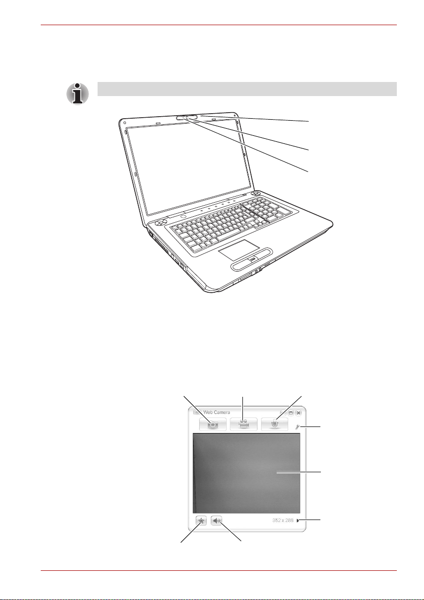
Using the Web Camera
This section describes the bundled webcam utility, which can capture still
and video images. The web camera will auto-run when Windows starts.
Please unstick the protective plastic-film before using the Web Camera.
* Provided with some models
Operating Basics
Built-in microphone *
Web Camera LED *
Web Camera Lens *
Using the software
The web camera software is pre-configured to start when you turn on
Windows Vista; if you need to restart it go to Start All Programs
Camera Assistant Software Camera Assistant Software.
Capture Still
Images
Effects Mute
User’s Manual 4-10
Video
Recording
Audio
Recording
Function
Display Window
Camera resolution
Page 77

Operating Basics
Capture Still Images Click to see a preview of the captured image; you
Video Recording Click to prepare for recording. Click again to start
Audio Recording Click to start recording, click again to stop and
Function Access additional functions: About, Player,
About Displays software manufacturer details.
Player Play video files.
Effects Choose images to be displayed on the capture
Properties Choose from the Options tab to flip, zoom, flicker
Settings Choose from the: Options tab to change the tool
Help Displays the help files for the software.
can also e-mail the image.
recording. One more to stop recording and see
preview of the video.
listen to a preview of the audio.
Effects, Properties, Settings and Help.
screen.
rate, night mode and backlight compensation; in
the Image tab change the color settings; in the
Profiles tab change the lighting conditions.
bar position; the Picture tab to select picture
output options such as size, export file and save
path; the Video tab to choose video output
settings such as Frame Rate, Size, Compression
and the frame rate, size, record compressor, and
save path; the Audio tab to change the audio
device, audio compressor, audio volume and
save path.
Using the microphone
Your computer has a built-in microphone that can be used to record
monaural sounds into your applications. It can also be used to issue voice
commands to applications that support such functions.(Built-in microphone
is provided with some models)
Since your computer has a built-in microphone and speaker, "feedback"
may be heard under certain conditions. Feedback occurs when sound from
the speaker is picked up in the microphone and amplified back to the
speaker, which amplifies it again to the microphone.
This feedback occurs repeatedly and causes a very loud, high-pitched
noise. It is a common phenomenon that occurs in any sound system when
the microphone input is output to the speaker (throughput) and the speaker
volume is too loud or too close to the microphone. You can control
throughput by adjusting the volume of your speaker or through the Mute
function in the Master Volume panel. Refer to your Windows documentation
for details on using the Master Volume panel.
User’s Manual 4-11
Page 78

Using the TOSHIBA Face Recognition
If your computer is equipped with a web camera, the TOSHIBA Face
Recognition feature can be used to verify the face of users when they log
on to Windows. If the verification is successful, a user will be logged on to
Windows automatically. The user can thus avoid having to enter a
password, which makes the login process easier.
■ TOSHIBA Face Recognition does not guarantee the correct
identification of a user. Changes to the likeness of a registrant, such as
hair style changes, wearing a cap, or wearing glasses may effect the
recognition rates when such changes occur after the registrant had
registered.
■ TOSHIBA Face Recognition may incorrectly recognize faces that are
similar to a registrant.
■ For high security purposes, TOSHIBA Face Recognition is not a
suitable substitute for Windows passwords. When security is a high
priority, use your established Windows passwords to log in.
■ Bright background light and/or shadows may prevent a registrant from
being recognized correctly. In that case, log in using your Windows
password. If recognition of a registrant fails repeatedly, refer to your
computer documentation to learn ways to improve recognition
performance.
Disclaimer
Toshiba does not guarantee that the face recognition utility technology will
be completely secure or error-free. Toshiba does not guarantee that the
face recognition utility will accurately screen out unauthorized users at all
times. Toshiba is not liable for any failure or damage that might arise out of
the use of the face recognition software or utility.
TOSHIBA, ITS AFFILIATES AND SUPPLIERS SHALL HAVE NO
RESPONSIBILITY FOR DAMAGE TO OR LOSS OF ANY BUSINESS,
PROFITS, PROGRAMS, DATA, NETWORK SYSTEMS OR REMOVABLE
STORAGE MEDIA ARISING OUT OF OR RESULTING FROM THE USE
OF THE PRODUCT, EVEN IF ADVISED OF THE POSSIBILITY
THEREOF.
When using the feature “Log Record function” of the Toshiba Face
Recognition software please make sure that the usage is in line with
applicable legal requirements especially data protection laws in your
country of usage as well as with company internal regulations if any.
Operating Basics
User’s Manual 4-12
Page 79

How to register the Face Recognition Data
Take a picture for facial verification purposes, and register the data needed
when you log in. To register the data needed when you log in, follow the
steps as described below:
1. To launch this utility, click Start All Programs TOSHIBA
Utilities TOSHIBA Face Recognition.
■ The Registration screen is displayed for a logged-in user whose
face has not been registered.
■ The Management screen is displayed for a logged-in user whose
face has already been registered.
2. If your a registered user click the Register face button in the
Management screen, otherwise the Registration screen will be
displayed.
■ If you wish to practice, click on the Next button in the Registration
screen.
■ If you do not wish to practice, click on the Skip button in the
Registration screen.
3. Click the Next button to start the guide.
4. First, take a picture while moving your neck slightly to the left and right.
5. Now take a picture while moving your neck down and up.
■ Click the Back button to practice the guide once more.
6. Click the Next button to start image-capturing process.
Adjust the position of your face so that it fits within the face-shaped
frame.
7. Once your face has been positioned properly, the recording will
commence.
Start moving your neck very slightly to the left and right, and then move
your neck up and down.
8. Registration will end after you have repeatedly moved your neck left,
right, down and up.
When the register succeeds, below message will be displayed on the
screen:
verification test. Click the Next button."
Click the Next button to perform the verification test.
9. Perform the verification test. Face the screen as you do when you
register.
■ If verification fails, click the Back button and re-register. Please refer
10. If verification is successful, click the Next button and register an
account.
11. Register the account.
Fill in the account registration fields.
"Registration successful. Now we’ll do the
to step 6 to step 8.
Operating Basics
.
User’s Manual 4-13
Page 80

■ Fill in the User Name, User Full name, Log on to, Password, and
Confirm password fields;
When you have finished it, click Next button.
12. The Management screen is displayed.
The registered account name will be displayed. Clicking on it will cause
the captured image of your face to be displayed on the left.
How to Delete the Face Recognition Data
Delete image data, account information, and personal record data created
during registration. To delete the Face Recognition Data, follow the steps
as described below:
1. To launch this utility, click Start All Programs TOSHIBA
Utilities TOSHIBA Face Recognition.
The Management screen is displayed.
2. Select a user which is deleted in the Management screen.
3. Click the Delete button.
user data. Would you like to continue?" will be
displayed on the screen.
■ If you do not want the data to be deleted, click the No button and
you will then be returned to the Management screen.
■ Clicking on the Yes button will remove the selected user from the
Management screen.
"You are about to delete the
Operating Basics
How to launch the help file
For further information on this utility, please refer to help file.
1. To launch the help file, click Start All Programs TOSHIBA
Utilities TOSHIBA Face Recognition Help.
Windows Logon via TOSHIBA Face Recognition
This section explains how to login to Windows with TOSHIBA Face
Recognition. Two authentication modes are provided.
■ AUTO Mode Login screen: If the face authentication file is selected by
default, you can log in without using the keyboard or mouse.
■ 1:1 Mode Login screen: This mode is essentially the same as AUTO
mode, but the Select Account screen will appear before the Display
Captured Image screen, and you will need to select the user account
to be authenticated in order to start the authentication process.
AUTO Mode Login screen
1. Turn on the computer.
2. The Select Tiles screen will be displayed.
3. Select the tile for facial authentication.
User’s Manual 4-14
Page 81

Operating Basics
4. "Please turn your face to the camera" will be
displayed.
5. Verification will be performed. If the authentication is successful, the
image data taken in step 4 will be faded in and placed over one another.
■ If an error occurs during authentication, you will be returned to the
Select Tiles screen.
6. Windows Welcome screen will be displayed, and will be logged in
automatically to Windows.
1:1 Mode Login screen
1. Turn on the computer.
2. The Select Tiles screen will be displayed.
3. Select the tile for facial authentication.
4. The Select Account screen will be displayed.
5. Select the account, and click the arrow button.
"Please turn your face to the camera" will be
6.
displayed.
7. Verification will be performed. If the authentication is successful, the
image data taken in step 6 will be faded in and placed over one another.
■ If an error occurs during authentication, you will be returned to the
Select Tiles screen.
8. Windows Welcome screen will be displayed, and will be logged in
automatically to Windows.
Using the optical disc drive
Operation is the same for all optical media drives. The full-size drive
provides high-performance execution of CD/DVD-based programs. You
can run either 12 cm (4.72") or 8 cm (3.15") CDs without an adaptor. An
ATAPI interface controller is used for CD/DVD operation. When the
computer is accessing a CD/DVD, an indicator on the drive glows.
Refer also to the Writing CD/DVD with the DVD Super Multi drive section
for precautions on writing to CD/DVD.
User’s Manual 4-15
Page 82

Loading discs
To load a disc, follow the steps below and refer to the figures.
1. a. When the power is on, press the eject button to open the drawer
slightly.
Eject Button
Pressing the eject button
b. Pressing the eject button will not open the drawer when the disc
drive's power is off. If the power is off, you can open the drawer by
inserting a slender object (about 15 mm) such as a straightened
paper clip into the eject hole just to the right of the eject button.
Operating Basics
Manual release with the eject hole
User’s Manual 4-16
Page 83
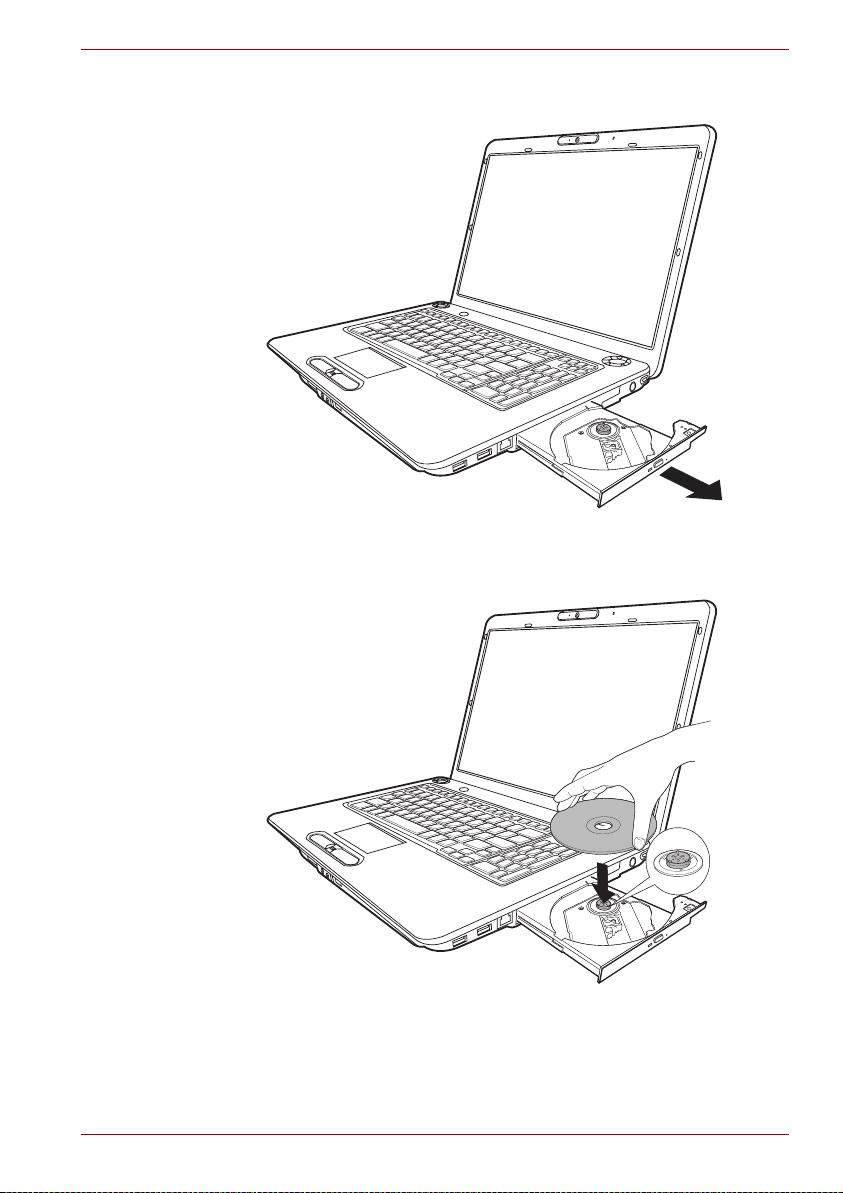
2. Grasp the drawer gently and pull until it is fully opened.
Pulling the drawer open
3. Place the disc, label side up, in the drawer.
Operating Basics
Inserting a disc
User’s Manual 4-17
Page 84

Operating Basics
When the drawer is fully opened, the edge of the computer will extend
slightly over the disc tray. Therefore, you will need to turn the disc at an
angle when you place it in the tray. After seating the disc, however, make
sure it lies flat, as shown in the figure above.
■ Do not touch the laser lens. Doing so could cause misalignment.
■ Keep foreign matter from entering the drive. Check the back edge of
the tray to make sure it carries no debris before closing the drive.
4. Press gently at the centre of the disc until you feel it click into place. The
disc should lie below the top of the spindle, flush with the spindle base.
5. Push the center of the drawer to close it. Press gently until it locks into
place.
If the disc is not seated properly when the drawer is closed, the disc might
be damaged. Also, the drawer might not open fully when you press the
eject button.
Closing the disc drawer
User’s Manual 4-18
Page 85
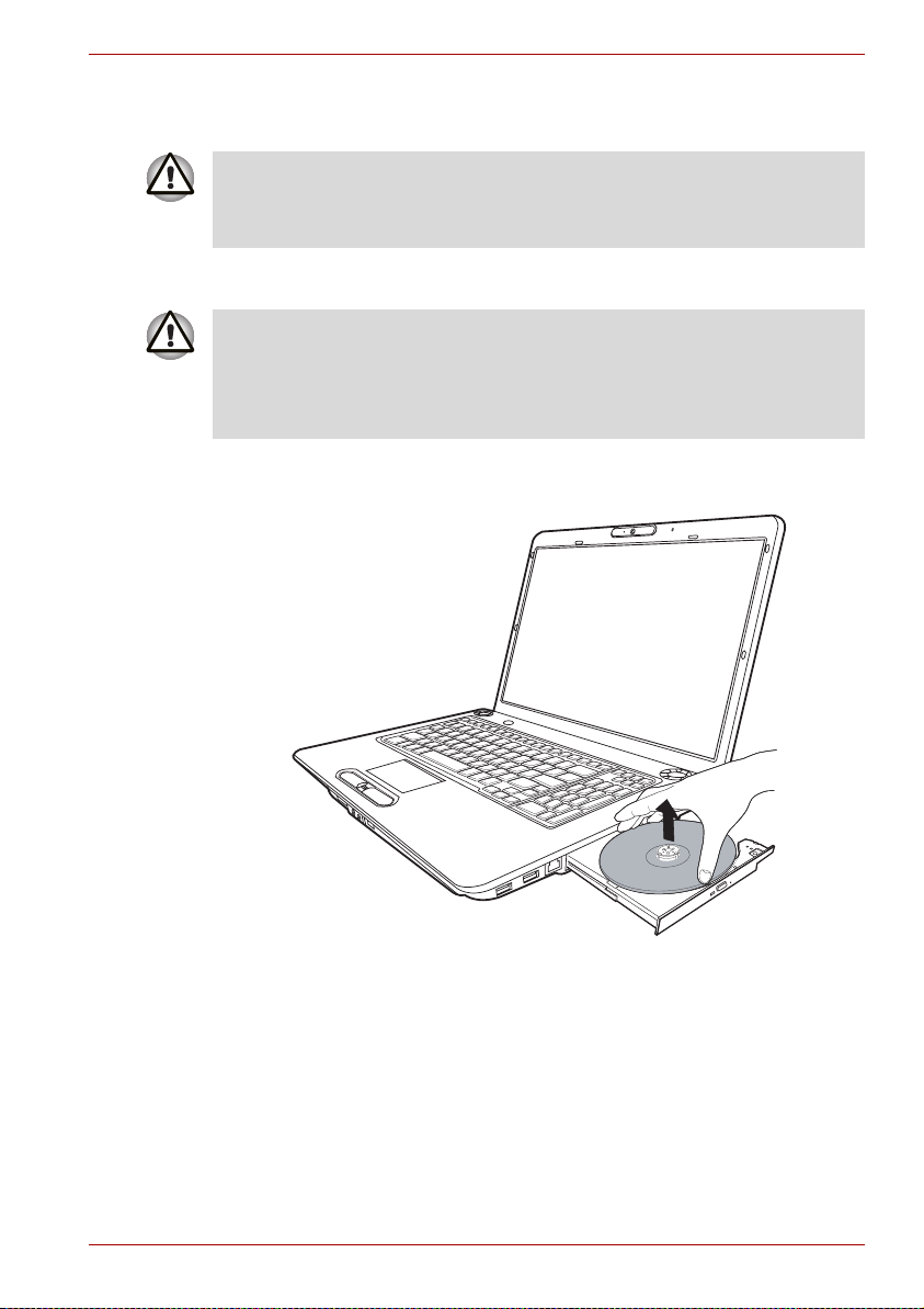
Removing discs
To remove the disc, follow the steps below and refer to the figure.
Do not press the eject button while the computer is accessing the disc
drive. Wait for the optical media drive indicator to go out before you open
the drawer. Also, if the disc is spinning when you open the drawer, wait for
it to stop before you remove it.
1. To pop the drawer partially open, press the eject button. Gently pull the
drawer out until it is fully opened.
■ When the drawer pops open slightly, wait a moment to make sure the
disc has stopped spinning before pulling the drawer fully open.
■ Turn off the power before you use the eject hole. If the disc is spinning
when you open the drawer, the disc could fly off the spindle and cause
injury.
2. The disc extends slightly over the sides of the drawer so you can hold it.
Hold the disc gently by its edges and lift it out.
Operating Basics
Removing a disc
3. Push the centre of the drawer to close it. Press gently until it locks into
place.
User’s Manual 4-19
Page 86

Writing CD/DVD with the DVD Super Multi drive
Some models in this series are equipped with Writing CD/DVD with the
DVD Super Multi drive.
You can use the DVD Super Multi drive to write data to either CD-R/RW or
DVD-R/-RW/+R/+RW/-RAM discs. The following applications for writing are
preinstalled: TOSHIBA Disc Creator and TOSHIBA Direct Disc Writer.
Ulead Movie factory for TOSHIBA.
Important message (DVD Super Multi drive)
Before you write or rewrite to CD-R/RW or DVD-R/-RW/+R/+RW/-RAM
discs, read and follow all setup and operating instructions in this section. If
you fail to do so, the DVD Super Multi drive may not function properly, and
you may fail to write or rewrite, lose data or incur other damage.
Before writing or rewriting
■ Based on TOSHIBA's limited compatibility testing, we suggest the
following manufacturers of CD-R/RW and DVD-R/+R/-RW/+RW/-RAM
discs. However, in no event does TOSHIBA guarantee the operation,
quality or performance of any disc. Disc quality can affect write or
rewrite success rates.
Operating Basics
CD-R: TAIYO YUDEN Co., Ltd.
CD-RW: MITSUBISHI KAGAKU MEDIA CO, LTD.
High Speed
CD-RW:
Ultra Speed
CD-RW:
DVD-R: DVD Specifications for Recordable disc for
DVD-R(DL): MITSUBISHI KAGAKU MEDIA CO, LTD.
DVD+R: MITSUBISHI KAGAKU MEDIA CO, LTD.
DVD+R(DL): MITSUBISHI KAGAKU MEDIA CO, LTD.
DVD-RW: DVD Specifications for Recordable Disc for
User’s Manual 4-20
MITSUBISHI KAGAKU MEDIA CO, LTD.
Ricoh Co., Ltd.
Hitachi Maxell Ltd.
Ricoh Co., Ltd.
MITSUBISHI KAGAKU MEDIA CO, LTD.
Ricoh Co., Ltd.
MITSUBISHI KAGAKU MEDIA CO, LTD.
General Version2.0
TAIYO YUDEN Co., Ltd.
Matsushita Electric Industrial Co., Ltd.
Ricoh Co., Ltd.
Version 1.1 or 1.2
Victor Company of Japan, Ltd. (JVC)
MITSUBISHI KAGAKU MEDIA CO, LTD.
Page 87

Operating Basics
DVD+RW: MITSUBISHI KAGAKU MEDIA CO, LTD.
DVD-RAM: DVD Specifications for DVD-RAM Disc for
Version2.0, 2.1 or 2.2
Hitachi Maxell Ltd.
Matsushita Electric Industrial Co., Ltd.
This drive cannot use discs that allow writing of 8 speeds or more (DVD-R,
DVD+R, DVD+RW), or 6 speeds or more (DVD-RW)
■ If the disc is poor in quality, dirty or damaged, writing or rewriting errors
may occur. Be careful to check the disc for dirt or damage before you
use it.
■ The actual number of rewrites to CD-RW, DVD-RW, DVD+RW or
DVD-RAM is affected by the quality of the disc and the way it is used.
■ There are two types of DVD-R discs: authoring and general use discs.
Do not use authoring discs. Only general use discs can be written to by
a computer drive.
■ We can support only Format1 of DVD-R DL. Therefore you cannot do
the additional writing. If your data is under 4.7 GB, we suggest to use
DVD-R (SL) media.
■ You can use DVD-RAM discs that can be removed from a cartridge and
DVD-RAM discs designed without a cartridge. You can not use a disc
with a 2.6 GB single-sided capacity and 5.2 GB double-sided capacity.
■ Other DVD-ROM drives for computers or other DVD players may not be
able to read DVD-R/-RW or DVD+R/+RW discs.
■ Data written to a CD-R/DVD-R/DVD+R disc cannot be deleted either in
whole or in part.
■ Data deleted (erased) from a CD-RW, DVD-RW, DVD+RW and
DVD-RAM disc cannot be recovered. Check the content of the disc
carefully before you delete it. If multiple drives that can write data to
discs are connected, be careful not to delete data from the wrong drive.
■ In writing to a DVD-R/-RW, DVD+R/+RW or DVD-RAM disc, some disc
space is required for file management, so you may not be able to write
the full capacity of the disc.
■ Since the disc is based on the DVD standard, it might be filled with
dummy data if the written data is less than about 1 GB. Even if you write
only a small amount of data, it might take time to fill in the dummy data.
■ DVD-RAM formatted by FAT32 cannot be read in WindowsR 2000
without DVD-RAM Driver Software.
■ When multiple drives that can write data to discs are connected, be
careful not to write to the wrong drive.
■ Be sure to connect the AC adaptor before you write or rewrite.
■ Before you enter Sleep Mode/Hibernation Mode, be sure to finish
DVD-RAM writing. Writing is finished if you can eject DVD-RAM media.
■ Be sure to close all other software programs except the writing
software.
User’s Manual 4-21
Page 88

■ Do not run software such as a screen saver, which can put a heavy load
on the CPU.
■ Operate the computer under the power scheme High Performance. Do
not use power-saving features.
■ Do not write while virus check software is running. Wait for it to finish
and then disable virus detection programs including any software that
checks files automatically in the background.
■ Do not use hard disc utilities, including those intended to enhance HDD
access speed. They may cause unstable operation and data damage.
■ Write from the computer's hard disc drive to the CD/DVD. Do not try to
write from shared devices such as a LAN server or any other network
device.
■ Writing with software other than TOSHIBA Disc Creator is not
recommended.
When writing or rewriting
Please observe/consider the following when you write or rewrite to a CD-R/
-RW, DVD-R/-RW/-RAM or DVD+R/+RW disc.
■ Do not perform any of the following actions when writing or rewriting:
■ Change users in the Windows® Vista operating system.
■ Operate the computer for any other function, including using a
mouse or TouchPad or closing/opening the LCD panel.
■ Start a communication application such as a modem.
■ Apply impact or vibration to the computer.
■ Install, remove or connect external devices, including the following:
ExpressCard, USB devices, external display, optical digital devices.
■ Use the audio/video control buttons to reproduce music or voice.
■ Open the DVD Super Multi drive.
■ Do not use shut down/log off and Sleep Mode/Hibernation Mode while
writing or rewriting.
■ Make sure writing or rewriting is completed before going into Sleep
Mode/Hibernation Mode. Writing is completed if you can open the DVD
Super Multi drive tray.
■ Set the computer on a level surface and avoid places subject to
vibration such as airplanes, trains, or cars. Do not use an unstable
surface such as a stand.
■ Keep mobile phones and other wireless communication devices away
from the computer.
■ Always copy data from the hard disk drive to the CD-R/-RW,DVD-R/
-RW/-RAM or DVD+R/+RW disc. Do not use cut-and-paste. The
original data will be lost if there is a write error.
Operating Basics
User’s Manual 4-22
Page 89

Disclaimer (DVD Super Multi drive)
TOSHIBA does not bear responsibility for the following:
■ Damage to any CD-R/RW or DVD-R/-RW/+R/+RW/-RAM disc that may
be caused by writing or rewriting with this product.
■ Any change or loss of the recorded contents of CD-R/RW or DVD-R/
-RW/+R/+RW/-RAM disc that may be caused by writing or rewriting with
this product, or for any business profit loss or business interruption that
may be caused by the change or loss of the recorded contents.
■ Damage that may be caused by using third party equipment or
software. Given the technological limitations of current optical disc
writing drives, you may experience unexpected writing or rewriting
errors due to disc quality or problems with hardware devices. Also, it is
a good idea to make two or more copies of important data, in case of
undesired change or loss of the recorded contents.
TOSHIBA Disc Creator
Note the following limitations when you use TOSHIBA Disc Creator:
■ DVD-Video cannot be created using TOSHIBA Disc Creator.
■ DVD-Audio cannot be created using TOSHIBA Disc Creator.
■ You cannot use the TOSHIBA Disc Creator "Audio CD" function to
record music to the DVD-R/-RW or DVD+R/+RW media.
■ Do not use the "Disc Backup" function of TOSHIBA Disc Creator to
copy.
■ DVD-Video and DVD-ROM with copyright protection. DVD-RAM media
cannot be backed up with the "Disc Backup" function of TOSHIBA Disc
Creator.
■ You cannot back up a CD-ROM or CD-R/RW to DVD-R/-RW or DVD+R/
+RW using the "Disc Backup" function of TOSHIBA Disc Creator.
■ You cannot back up DVD-ROM, DVD-Video or DVD-R/-RW or DVD+R/
+RW to CD-R/RW using TOSHIBA Disc Creator.
■ TOSHIBA Disc Creator cannot record in packet format.
■ You might not be able to use the Disc Backup function of TOSHIBA
Disc Creator to backup a DVD-R/-RW or DVD+R/+RW disc that
wasmade with other software on a different DVD-R/-RW or DVD+R/
+RW recorder.
■ If you add data to a DVD-R and DVD+R disc that you have already
recorded to, you might not be able to read the added data under some
circumstances. It cannot be read in 16-bit operating systems, such as
Windows 98SE and Windows ME, in Windows NT4 you will need
Service Pack 6 or later to read the data, and in Windows 2000 you will
need Service Pack 2 or later to read it. Some optical media drives
cannot read added data regardless of the operating system.
■ TOSHIBA Disc Creator does not support recording to DVD-RAM discs.
To record to a DVD-RAM, use Explorer or other similar utility.
Operating Basics
User’s Manual 4-23
Page 90

■ When you back up a DVD disc, be sure the source drive supports
recording to DVD-R/-RW or DVD+R/+RW discs. If the source drive
does not support recording to DVD-R/-RW or DVD+R/+RW discs, it
might not be backed up correctly.
■ When you back up a DVD-R, DVD-RW, DVD+R or DVD+RW, be sure to
use the same type of disc.
■ You cannot partially delete any data written to a CD-RW, DVD-RW or
DVD+RW disc.
Data Verification
To verify that data has been written or rewritten correctly to a data CD/DVD
you should follow the steps below before you begin the write/rewrite process:
1. Display the setting dialog box by one of the following two steps:
■ Click the Recording settings button( ) for writing on the main
toolbar in the Data Disc mode.
■ Select Setting for Each Mode Data Disc in the Setting menu.
2. Mark the Verify written data check box.
3. Select File Open or Full Compare mode.
4. Click the OK button.
How to learn more about TOSHIBA Disc Creator
Please refer to the Help files for additional TOSHIBA Disc Creator
information.
Operating Basics
Video
You can record video using Ulead DVD MovieFactory® for TOSHIBA.
When using Ulead DVD MovieFactory® for TOSHIBA
How to make a DVD-Video
Simplified steps for making a DVD-Video from video data captured from a
DV-Camcorder:
1. Click All Programs MovieFactory for TOSHIBA Ulead
MovieFactory for TOSHIBA Launcher to launch MovieFactory.
2. Insert a DVD-RW or DVD+RW disc in Burner.
3. Click Video Disc Burn Video to Disc to launch Direct Recording
dialog box, choose DVD-Video/+VR to invoke Straight Capture to
Disc Page.
4. Choose DVD-Video format.
5. Confirm the capture source is DV.
User’s Manual 4-24
Page 91

6. Press Capture button.
Simplified steps for making a DVD-Video from adding video source:
1. Click All Programs MovieFactory for TOSHIBA Ulead
MovieFactory for TOSHIBA Launcher to launch MovieFactory.
2. Click Video Disc New Project to invoke 2
project type, then invoke MovieFactory.
3. Add source from HD Disk by click Add video files button to invoke
browser dialog box.
4. Choose the source video then go to Next page to apply Menu.
5. After choose the menu template, press Next button to go to Burning
Page.
6. Choose the output type then press Burn button.
nd
Launcher, choose your
How to learn more about Ulead MovieFactory
Please refer to the Help and Manual files for additional Ulead MovieFactory
information.
Important information for use
Note the following limitations when you write Video DVD:
1. Editing digital video
■ Log in with Administrator rights to use MovieFactory.
■ Make sure that your computer is running on AC power when using
MovieFactory.
■ Operate the computer at Full Power. Do not use power-saving
features.
■ While you are editing DVD, you can display previews. However, if
another application is running the preview might not display
properly.
■ MovieFactory cannot edit or play copy protected content.
■ Do not enter sleep or hibernation mode while using MovieFactory.
■ Do not operate MovieFactory immediately after turning on the
computer. Please wait until all Disc Drive activity has stopped.
■ When recording to a DV-Camcorder, to ensure you capture all of
your data, let the camcorder record for a few seconds before you
begin recording your actual data.
■ CD recorder, JPEG functions, DVD-Audio, mini DVD and Video CD
functions are not supported in this version.
■ While recording video to DVD, please close all other programs.
■ Do not run software like a screen saver because it can put a heavy
load on the CPU.
■ Do not support mp3 decode and encode.
Operating Basics
User’s Manual 4-25
Page 92

Operating Basics
2. Before recording the video to DVD
■ When you record DVD disc, please use only discs recommended by
the Drive manufacturer.
■ Do not set the working drive to a slow device like a USB1.1 hard
disk drive or it will fail to write DVD.
■ Do not perform any of the following actions:
■ Operate the computer for any other function, including using a
mouse to TouchPad or closing/Opening the LCD panel.
■ Bump or cause vibration to the computer.
■ Use the Mode control button and Audio/Video control button to
reproduce music or voice.
■ Open the DVD drive.
■ Install, remove or connect external devices, including the
following: ExpressCard, SD card, USB devices, external display,
i.LINK. devices, optical digital devices.
■ Please verify your disc after recording important data.
■ DVD-R/+R/+RW disc cannot be written in VR format.
■ Not support to output VCD and SVCD format.
3. About Straight to Disc
■ Not support to record on DVD-R/+R disc
■ Not support to record DVD+VR format by HDV
■ HDV support to burn DVD-Video only
■ DVD-VR format not support to add Menu
4. About recorded DVDs
■ Some DVD-ROM drives for personal computers or other DVD
players may not be able to read DVD-R/+R/-RW/-RAM discs.
■ When playing your recorded disc on your computer, please use the
DVD Video Player
■ If you use an over-used rewritable disc, the full formatting might be
locked. Please use a brand new disc.
Media care
This section provides tips on protecting data stored on your CD/DVD.
Handle your media with care. The following simple precautions will
increase the lifetime of your media and protect the data stored on them:
CD/DVD
1. Store your CD/DVD in the container they came in to protect them and
keep them clean.
2. Do not bend the CD/DVD.
3. Do not write on, apply a sticker to, or otherwise mar the surface of the
CD/DVD that contains data.
User’s Manual 4-26
Page 93

Modem
Operating Basics
4. Hold the CD/DVD by its outside edge or the edge on the centre hole.
Fingerprints on the surface can prevent the drive from properly reading
data.
5. Do not expose to direct sunlight, extreme heat or cold. Do not place
heavy objects on your CD/DVD.
6. If your CD/DVD become dusty or dirty, wipe them with a clean dry cloth.
Wipe from the centre out, do not wipe in a circular direction around the
CD/DVD. If necessary, use a cloth dampened in water or a neutral
cleaner. Do not use benzine, thinner or similar cleaner.
Some models has a built in modem.
This section describes how to connect and disconnect the internal modem
to and from a telephone jack.
The internal modem does not support voice functions. All data and fax
functions are supported.
■ In case of a lightning storm, unplug the modem cable from the
telephone jack.
■ Do not connect the modem to a digital telephone line. A digital line will
damage the modem.
Region selection
Telecommunication regulations vary from one region to another, so you will
need to make sure the internal modem's settings are correct for the region
in which it will be used.
To select a region, follow the steps below.
1. Click start, point to All Programs, TOSHIBA, Networking, and click
Modem Region Select.
Do not use the Country/Region Select function in the Modem setup utility
in the Control Panel if the function is available. If you change the Country/
Region in the Control Panel, the change may not take effect.
2. The Region Selection icon will appear in the Task Bar. Click the icon
with the primary mouse button to display a list of regions that the
modem supports. A sub menu for telephony location information will
also be displayed. A check will appear next to the currently selected
region and telephony location.
3. Select a region from the region menu or a telephony location from the
sub-menu.
■ When you click a region it becomes the modem's region selection,
and the New Location for telephony will be set automatically.
■ When you select a telephony location, the corresponding region is
automatically selected and it becomes the modem's current region
setting.
User’s Manual 4-27
Page 94

Properties menu
Click the icon with the secondary mouse button to display properties menu
on the screen.
Settings
You can enable or disable the following settings:
AutoRun Mode
The Region Select utility starts automatically when you start up the
operating system.
Open the Dialling Properties dialog box after selecting
region
The dialing properties dialog box will be displayed automatically after you
select the region.
Location list for region selection
A submenu appears displaying location information for telephony.
Open dialog box, if the modem and Telephony Current
Location region code do not match
A warning dialog box is displayed if current settings for region code and
telephony location are incorrect.
Operating Basics
Modem Selection
If the computer cannot recognize the internal modem, a dialog box is
displayed. Select the COM port for your modem to use.
Dialing Properties
Select this item to display the dialing properties.
If you are using the computer in Japan, the Telecommunications Business
Law requires that you select Japan region mode. It is illegal to use the
modem in Japan with any other selection.
User’s Manual 4-28
Page 95

Connecting
To connect the modem cable(optional), follow the steps below.
■ The modular cable that comes with the computer must be used to
connect a modem. Connect the end of the modular cable with the core
to the computer.
■ In case of a lightning storm, unplug the modem cable from the
telephone jack.
■ Do not connect the modem to a digital telephone line. A digital line will
damage the modem.
1. Plug one end of the modular cable into the modem jack.
2. Plug the other end of the modular cable into a telephone jack.
Operating Basics
Connecting the internal modem
Do not pull on the cable or move the computer while the cable is
connected.
Disconnecting
To disconnect the internal modem cable(optional), follow the steps below.
1. Pinch the lever on the connector in the telephone jack and pull out the
connector.
2. In the same way, pull the cable’s other connector out of the computer.
User’s Manual 4-29
Page 96

Using the FM tuner
The availability of this feature is depending on the model you purchased.
1. Plug the FM tuner antenna into the FM Antenna Jack.
FM Antenna Jack
2. Select Start All Programs FM Tuner Utility to start FM software.
Wireless communications
The computer’s wireless communication function supports both Wireless
LAN and Bluetooth devices.
■ Do not use the Wireless LAN (Wi-Fi) or Bluetooth functionalities near a
microwave oven or in areas subject to radio interference or magnetic
fields. Interference from a microwave oven or other source can disrupt
Wi-Fi or Bluetooth operation.
■ Turn Wi-Fi and Bluetooth functionalities off when near a person who
may have a cardiac pacemaker implant or other medical electric
device. Radio waves may affect pacemaker or medical device
operation, possibly resulting in serious injury. Follow the instruction of
your medical device when using any Wi-Fi or Bluetooth functionality.
■ Always turn off Wi-Fi or Bluetooth functionality if the computer is near
automatic control equipment or appliances such as automatic doors or
fire detectors. Radio waves can cause malfunction of such equipment,
possibly resulting in serious injury.
■ It may not be possible to make a network connection to a specified
network name using the ad hoc network function.
If this occurs, the new network (*) will have to be configured for all
computers connected to the same network in order to re-enable
network connections.
* Please be sure to use new network name.
Operating Basics
FM tuner antenna
User’s Manual 4-30
Page 97

Wireless LAN
Where present, it supports the A,B, G and draft N standards but it is
compatible with other LAN systems based on Direct Sequence Spread
Spectrum/Orthogonal Frequency Division Multiplexing radio technology
that complies with IEEE802.11 Wireless LAN standard.
■ Automatic Transmit Rate Select mechanism in the transmit range of 54,
48, 36, 24, 18, 12, 9 and 6 Mbit/s. (IEEE 802.11a/g)
■ Automatic Transmit Rate Select mechanism in the transmit range of 11,
5.5, 2 and 1 Mbit/s. (IEEE 802.11b)
■ Roaming over multiple channels
■ Card Power Management
■ Wired Equivalent Privacy (WEP) data encryption, based on the 128 bit
encryption algorithm.
■ Advanced Encryption Standard (AES) data encryption, based on 128 bit
encryption algorithm.
Security
■ Be sure to enable the encryption function otherwise you may expose
your computer to illegal access by an outsider across the Wireless LAN
which may cause intrusion, eavesdropping, and the loss or destruction
of stored data. TOSHIBA strongly recommend the customer to enable
the encryption function.
■ TOSHIBA is not liable for the eavesdropping of data due to the use of
Wireless LAN and the damage thereof.
Operating Basics
Bluetooth Stack for Windows by TOSHIBA (depends on the model
purchased)
Please note that this software is specifically designed for the following
operating systems:
■ Microsoft
Detailed information regarding the use with these operating systems is
listed below. Please refer also to the electronic information which is
included with each software.
This Bluetooth Stack is based on Bluetooth Version 1.1/1.2/2.0/2.1+EDR
specification. TOSHIBA cannot confirm compatibility between any PC
products and/or other electronic devices that use Bluetooth other than
TOSHIBA notebook computers.
®
Windows Vista™
Release Notes related to the Bluetooth Stack for Windows
by TOSHIBA
1. Fax application software:
Regarding FAX application software, there are some software that you
cannot use on this Bluetooth Stack.
User’s Manual 4-31
Page 98

2. Multi User:
On Windows Vista™, the use of Bluetooth is not supported in a multi-
user environment. This means that, when you use Bluetooth, other
users logged onto the same computer will not be able to use its
Bluetooth functionality.
Product Support
The latest information regarding Operating System support, Language
Support or available upgrades can be found on our web site
http://www.toshiba-europe.com/computers/tnt/bluetooth.htm in Europe or
http://www.pcsupport.toshiba.com in the United States.
Wireless communication switch
You can enable or disable the Wireless LAN function, with the on/off switch.
No transmissions are sent or received when the switch is off. Slid the
Switch to turn it on and turn it off.
Set the switch to off in airplanes and hospitals. Check the indicator. It will
stop glowing when the wireless communication function is off.
Wireless activity LED
The wireless activity LED indicates the status of the wireless
communication functions.
Operating Basics
Indicator status Indication
LED off Wireless communication switch is set to off.
LED glows Wireless communication switch is on. Wireless
If you used the Task Bar to disable Wireless LAN, you will need to restart
the computer to re-enable it. Alternatively, you can also follow this
procedure:
1. In the Control Panel, click System and Maintenance.
2. Click the Device Manager. The Device Manager window opens. Click
Network adaptors.
3. Select your preferred Network adaptor, then click the Enable button in
the tool bar.
User’s Manual 4-32
Automatic power down because of overheating.
Power malfunction
LAN is turned on by an application.
Page 99

LAN
The computer has built-in support for Fast Ethernet LAN or Giga bit
Ehternet LAN (depends on the model you purchased).
LAN cable types
The computer must be configured properly before connecting to a LAN.
Logging onto a LAN using the computer's default settings could cause a
malfunction in LAN operation. Check with your LAN administrator
regarding set-up procedures.
If you are using Fast Ethernet LAN (100 megabits per second,
100 BASE-TX), be sure to connect with a CAT5 cable or higher. You cannot
use a CAT3 cable.
If you are using Giga bit Ethernet LAN, be sure to connect with a CAT5-E
cable or higher. You cannot use a CAT5 or a CAT3 cable.
Connecting LAN cable
To connect the LAN cable, follow the steps below.
1. Turn off the power to the computer and to all external devices
connected to the computer.
2. Plug one end of the cable into the LAN jack. Press gently until you hear
the latch click into place.
Operating Basics
Connecting the LAN cable
3. Plug the other end of the cable into a LAN hub connector. Check with
your LAN administrator before connecting to a hub.
User’s Manual 4-33
Page 100

Disconnecting LAN cable
To disconnect the LAN cable, follow the steps below.
1. Pinch the lever on the connector in the computer's LAN jack and pull
out the connector.
2. Disconnect the cable from the LAN hub in the same manner. Check
with your LAN administrator before disconnecting from the hub.
Cleaning the computer
To help ensure long, trouble-free operation, keep the computer free of dust
and use care with liquids around the computer.
■ Be careful not to spill liquids into the computer. If the computer does get
wet, turn the power off immediately and let the computer dry completely
before you turn it on again.
■ Clean the computer using a slightly damp (with water) cloth. You can
use glass cleaner on the display. Spray a small amount of cleaner on a
soft, clean cloth and wipe the screen gently with the cloth.
Never spray cleaner directly onto the computer or let liquid run into any
part of it. Never use harsh or caustic chemical products to clean the
computer.
■ Remove the dust from the cooling vents on the Left side of the
computer regularly with a vacuum cleaner. Refer to Chapter 2, The
Grand Tour Left side.
Operating Basics
Moving the computer
The computer is designed for rugged durability. However, a few simple
precautions taken when moving the computer will help ensure trouble-free
operation.
■ Make sure all disk activity has ended before moving the computer.
Check the HDD indicator on the computer.
■ If a CD/DVD is in the drives, remove it. Also make sure the disc tray is
securely closed.
■ Turn off (shut down) the computer.
■ Disconnect the AC adaptor and all peripherals before moving the
computer.
■ Close the LCD display panel. Do not pick up the computer by its display
panel.
■ Before carrying your computer, shut down the computer, disconnect the
power cable and wait until the PC cools down. Failure to follow this
instruction could result in minor injury.
■ Always turn off the power when you move the computer. If the power
button has a lock, set it to the lock position. Also be careful not to
subject the computer to impact. Failure to follow this instruction could
result in damage to computer, computer failure or loss of data.
User’s Manual 4-34
 Loading...