

OIS PRODUCTS
KEY PADS
OIS10/20
2 Line x 16 Display
OIS40/40R
4 Line x 20 Display
TOUCH SCREENS
OIS15
4 Line x 16 Display
OIS120
12” Color Display
OIS50
OIS60
6” Color Display
2

KEY FEATURES
Ethernet Port on OIS120
Use for programming, connection to PLC, or connection to higher level controller. Communicate
across the plant or across the country.
Multi Language Capability
Display text information in any Microsoft supported language. Export text file to co-worker in
another country so that he can add his language. Then import text into OISeup32 software.
Pop Up Screens & Keypads
Conserve screen space on touchscreens by popping up a keypad for data entry. Press a flashing
alarm button to display a detailed alarm screen.
Alarm and Event Monitoring
Monitor status of alarms and specific events on one screen.
Trending
Touchscreens can display process trends graphically for easy interpretation of process/machine
history.
Horizontal or Vertical Orientation
Mount the touchscreen so that it best fits the application. Screens can be created in either
horizontal or vertical format.
Support for Floating Point Data
IEEE format double register data can be attached to any screen object such as bargraphs, meters,
etc.
Serial Port Available for Printing Screens and Alarm Data
Send PLC or connected device information to any serial printer.
Low Cost OEM Keypad Models that Require No Programming Software
Use large memory capacity of Toshiba PLC to store messages and perform data entry.
Keypad Overlays Ship Separately on most Keypad Models
Allows OEMs to easily add custom overlay for specific application.
3

OVERVIEW
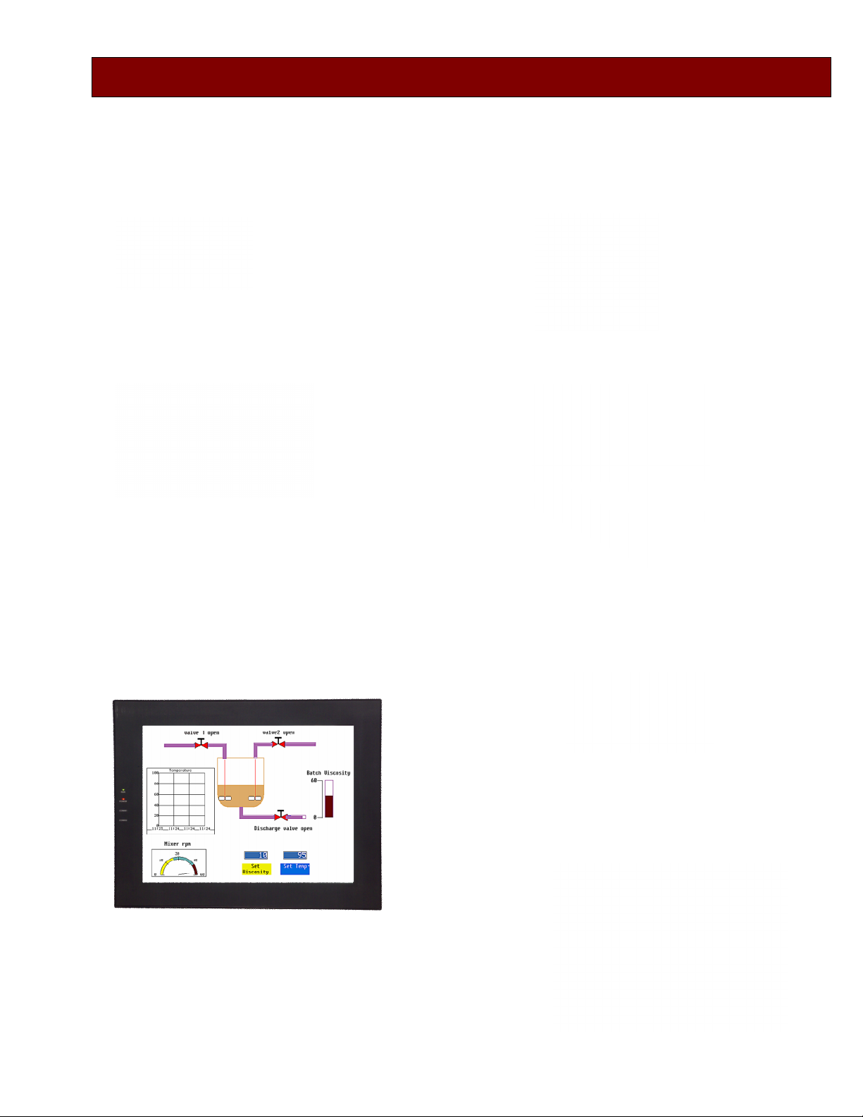
Color Touch Screens
Operator Interface Stations For Toshiba
Industrial Euipment
Controllers
Speed Drives
Controllers
I want to communicate with Toshiba
4
TOUCHSCREENS
Programming
OIS operation is based on screens and tasks. Screens are created with objects on the screen.
Tasks are assigned to the objects. The maximum limit to the number of screens that can be
created is 65,534 (based on available memory). Up to 256 alarms can be defined. Recipes can be
block transferred between the OIS and connected devices (or vice versa). The following
connection modes are possible:
1 : 1 OIS connected to one device.
1 : N One OIS connected to multiple devices
N : 1 Multiple OISs connected to one device
(Requires Gateway Protocol Converter).
Before the OIS can be used a program must be loaded into it. The program is created on any MS
Windows based computer using the OISetup32 software. The OISetup32 software creates nodes,
tasks, tags and screens. Tasks and tags are then assigned to the screens and to objects on the
screens. Available tasks are:
► Go To Screen ► Call Popup ► Display Trend
► Write Value to Tag ► Add Constant to Tag ► Subtract Constant from Tag
► Copy Tag A to Tag B ► Swap Tag A & Tag B ► Copy Tag to LED
► Copy PLC Bk to Recipe Bk ► Copy Recipe Bk to PLC Bki ► Print Data
► Turn Bit ON ► Turn Bit OFF ► Toggle Bit
The setup screen with floating tools bars, text grid and touch grid (grids are adjustable)
is used to create screens with objects. Tasks are then assigned to the objects..
Notes: 1. Most new features require Ver. 3.11 or higher.
2. Ver. 3.11 requires MS Windows 2000 or higher.
5

Multiple Language
OIS50
Мы Показываем
русский язык
Se Habla Muchos
Idiomas de Espanol
私たちは、
日本語が話せます
Language, We can Display It
Nous Parlons
le Français
Different English
Let Us Speak
Your Language
If multiple languages are present in the OIS, the user can toggle back and forth between languages. There
are two ways to add multiple languages to the OIS. 1st, the program developer can enter labels in both
languages during program development in the OISeut32 software. Or 2nd, the program developer can export
labels/text objects to an ASCII file with the language conversion utility. Then the ASCII file can be sent to
another person who is native in the second language. This person can add the translations to the text file
and send it back to the developer who then imports it back into the OISetup32 software.
Multi-State Indicators
Colors and text can change based on ON/OFF bit status or register values in the PLC. For OIS50
(monochrome LCD) varying gradient fill patterns can be used to represent different states. Not satisfied with
the available indicators? The OISetup32 software allows importing of custom designed bitmap objects that
can be used in place of available objects.
6

Meters, Bargraphs & Switches
A wide variety of predefined meters, bargraphs, buttons, and switches are available for insertion on an OIS
development screen. User defined bitmap images can be imported into the OISetup32 software and used
just like predefined buttons and switches.
PV SV MV
Meters and bargraphs are very
customizable. Shape, orientation, fill,
color, text and labels are all modifiable.
Switch Pairs: One or the other appearsdepending on status of a bit in the PLC.
Toggle
Trending
Trending is an important requirement in most
process applications and many machine control
applications. Displaying trends graphically
provides easier interpretation of process/system
change. Two types of trending are available in
the OIS60 and 0IS120.
1. Simple Trending: Variables are displayed
on the user defined screen. Variables are on
the Y-axis and time is on the X-axis. Time is
displayed in seconds / minutes by user
defined increments. The bar colors and the
number of grid lines are also user definable.
2. Historical Trending: Historical trending is simple trending plus data logging. With historical trending the
data values are saved to the OIS internal memory. When to start and stop trending is user defined. What to
do when OIS memory is fully (stop or overwrite) is user defined. In the data logger 4 groups can be defined,
each group containing up to 32 tags. When to start logging and stop logging is user definable for each group.
Multiple trending windows can be displayed but each window is limited to 4 tags.
7

Popup Keypads for Data Entry
Hub
Numeric Keypad Hex Keypad
On/Off Keypad
Horizontal or Vertical Orientation
OISetup32 software allows the display to be
oriented in the most advantageous position for the
operator (or as necessary based on available front
panel space). Simply rotate the objects or text in
the direction desired when setting up the display in
the OISetup32 software.
Ethernet Connection (OIS120)
A variety of keypads are available
to simplify data entry. The
keypads can be incorporated into
screen design or can be “poped
up” when a button or other object
is pressed on the screen so that
they appear only when needed.
Key text, key size and keypad
color are all user defineable.
Requires OISetup32 Ver. 3.11 or higher
Multiple OIS120s can connect to S2T PLCs (with the GEN651A Ethernet Module) in a 100 Mhz Ethernet
network.
S2T
Ethernet
S2T
Requires OISetup32 Ver. 3.11 or higher
8

KEYPADS
Low Cost Non Programmable Models
OIS15
4 Line x 16 Display
8 Function Keys
4 Indicator LEDs
Power from PLC
OIS10
2 Line x 16 Display
6 Function Keys
2 Indicator LEDs
Power from PLC
The OIS10/15 are economical,low cost, OEM type operator interface stations. They have no external power
connections, they have no memory; they depend exclusively on the PLC. Fortunately Toshiba’s T1 Series
PLCs have additional power and memory capacity to make the OIS10/15 very powerful operator interface
stations. For detailed examples on how to make the OIS10/15 into full function operator interface stations
please see Toshiba’s T-Series Quick Start Manual. Keypad overlays are shipped separately. They can be
easily be replaced by OEM custom Keypad overlays.
Message Display: Store ASCII messages in the ladder logic
OIS’s Love
Toshiba PLCs!
They have lots
of Memory
9

Data Entry: Create a menu of screens for changing different parameters.
____
OIS10
F1 Mtr1 F2 Mtr2
Message Display
Mtr1 Prev 3000
F5 Rtn New
Press F4
Message Display
Mtr3 Prev 1800
Message Display
Mtr2 Prev 2520
F5 Rtn New____
Message Display
Mtr4 Prev 0900
F5 Rtn New____
Data Entry for New
Speed Setting, at
Flashing Line
ANNUNCIATOR LEDs: The OIS10 has 2 user definable LEDs, the OIS15 has 4 user definable
LEDs. Each LED can be turned ON or OFF when a designated coil or bit in the PLC is ON or
OFF. Each designated LED can also be turned ON when one of the following occurs: A register
value is less than, equal to, or greater than a specified limit.
OIS40/40R
OIS40 OIS40R
Display 4 lines x 20 ch. 4 lines x 20 ch.
Power From PLC Separate 24 Vdc
Connection PLC RS232 Port PLC RS485 Port
Prgm Sfwr OISetup32 OISetup32
Fun Keys 8 8
LEDs 8 8
The OIS40 and the OIS40R have full function
numerical keypads for applications requiring
repetitive data entry.
The OIS40R is the remote version with the RS485 connection to the PLC. It can be mounted up to
1000 meters ( 0.6 miles) away from the PLC. One (1) OIS40R can talk to multiple PLCs. Both the
OIS40 and the OIS40R use the same OISetup32 software used by the touchsceen OISs.
10

SPECIFICATIONS
General Specifications
Operating Temperature:0o
Storage Temperature:
Humidity: 10%to 90% (Non condensing)
Immunity to ESD: Level 3 as per IEC1000-4-2
Immunity to Transients: Level 3 as per IEC1000-4-4
Radiated Susceptibility: Level 3 as per IEC1000-4-3
Emissions: EN55011 CISPR A
OIS120
Display: 12.1” TFT (800 x 600 Pixels) GraphicalColor Display(256 Colors)
Display Rating: IP 65 rated Touch Screen.
Panel Cutout: 294mm x 226 mm.
Communication Ports: Two ports, one connectsto the PLC and one for programming, serial
Ethernet Port: Connects to PLC, Available for Programming or Use for Remote Monitoring.
Certifications: CE,
Power: 24Vdc + 10%, 20 W maximum, Inrush 2 A.
Weight: 2.8 Kg.
OIS60
C to 50oC
-20oC to 80oC
printing or connecting to another device with different protocol.
RS232/485/CMOSlevels available.
OIS50
Display: 6” diagonal QVGA, 320 x240 pixel, 256 color, Backlit .
Display Rating: IP 65 rated Touch Screen.
Panel Cutout: 183.13mm x 125.12mm.
Communication Ports: Two ports, one connectsto the PLC and one for programming, serial
printing or connectingto another device with different protocol.
RS232/485/CMOSlevels available.
Certifications: CE,
Power: 24Vdc + 10%, 3 W maximum.
Weight: 645 g.
Display: 4.1" 192 x 64 pixel LCD Graphical Display.
Display Rating: IP 65 rated Touch Screen.
Panel Cutout: 132.2 mm x68.6 mm.
Communication Ports: Two ports, one connectsto the PLC and one for programming, serial
printing or connectingto another device with different protocol.
RS232/485/CMOSlevels available.
Certifications: CE,
Power: 24Vdc + 10%, 3 W maximum.
Weight: 276 g.
11

OIS40/40R
Display: 4 Line x 20 Character Backlit LCD.
Display Rating: IP 65 rated Keypad
Keys 8 FunctionUser Assignable Keys & 0 – 9 Numeric Data Entry Keys
LEDs 8
Panel Cutout: 162 mm x 79 mm.
Communication Ports: OIS40R: Two ports, one connectsto the PLC and one for programming or
Certifications: CE,UCSA
Power: OIS40R: 24 Vdc + 10%, 2 W maximum.
Weight: OIS40: 235g. OIS40R: 350 g.
OIS20
Display: 2Line x 16 Character Backlit LCD.
Display Rating: IP 65 rated Keypad
Keys 6 User AssignableFunction Keys.
LEDs 2 (1 Red & 1 Green)
Panel Cutout: 92 mm x 45 mm (1/8 DIN).
Communication Ports: Two ports, one connectsto the PLC and one for programming or serial
Certifications: CE,UCSA
Power: 5 Vdc + 5%, 120 mA from PLC Port.
Weight: 140 g.
serial printing.
OIS40: 5 Vdc + 5%, 160 mA from PLC Port.
printing.
OIS10/15
Display: OIS10: 2 Line x 16 Character Backlit LCD.
Display Rating: IP 65 rated Keypad
Keys OIS10: 6 User Assignable Function Keys.
LEDs OIS10: 2 (1 Red & 1 Green)
Panel Cutout: OIS10: 92mm x 45 mm. (1/8 DIN).
Communication Ports: Oneport connects to the PLC.
Certifications: CE,UCSA
Power: 5 Vdc + 5%, 120 mA from PLC Port.
Weight: OIS10: 140 g. OIS15: 240g.
OIS16: 4 Line x 16 Character Backlit LCD.
OIS15: 8 User Assignable Function Keys.
OIS15: 4 Red.
OIS15: 92 mm x 92 mm (1/4 DIN).
12

DIMENSIONS
OIS
OIS
120
13

ORDER INFORMATION
Operator Interface Stations
Part Number Description
OIS120 12” SVGA Color Touch Panel, Requires 24 Vdc PS. RequiresOISetup32 Software.
OIS60 6” QVGA Color Touch Panel, Requires 24 Vdc PS. RequiresOISetup32 Software.
OIS50 4.1” LCD Touch Panel, Requires 24 Vdc PS. Requires OISetup32 Software.
OIS40R 4 Line x 20 Character Display with Keypad, 8 Function Keys, 8 LEDs, Requières 24
Vdc PS. Requires OISetup32 Software.
OIS40 4 Line x 20 Character Display with Keypad, 8 Function Keys, 8 LEDs. Power from
PLC. Requires OISetup32 Software.
OIS20 2 Line x 16 Character Display, 6 Function Keys, 2 LEDs. Power from PLC. Requires
OISetup Software.
OIS15 4 Line x 16 Character backlit LCD Display, 8 FunctionKeys, 4 LEDs. No
Programming-- Messages & Functions are stored in PLC. Power from PLC. Comes
with cable for T1
OIS10 2 Line x 16 Character backlit LCD Display, 6 Function Keys, 2 LEDs. No
Programming--Messages & Functions are stored in PLC. Powerfrom PLC. Comes
with cable for T1.
Note: Some OIS have two 9 pin D shell female connectors. These are Node 1 & 2 for connectingto devices with
different protocols. Either can be used to download an application program.
Cables
Part Number Description
IBM-0909-1-00 Cable, Programming, Connects OIS to Computer for downloading application
program.
SC-P-019A-00 Cable, Connects OIS40R & all Touchscreensto T1, 9 pin D Shell to 8 pin Mini DIN, 2
m.
SC-P-019B-00 Cable, Connects OIS40R & all Touchscreensto T2E/T2N/T3/S2E/S2T RS232 port, 9
pin D Shell to 9 pin D Shell, 2 m.
SC-P-046A-00 Cable, ConnectsOIS40R & all Touchscreensto RS485 port, Pigtail on
T1/T2/S2E/S2T end, 2 m.
SC-P-046B-00 Cable, ConnectsOIS40R & all Touchscreensto T2N/T3 RS485 port (DB 15
connector), 2 m
EC-I-019A-00 Cable, Connects new OIS40 to T1 Programming Port, 2 m
EC-I-019B-00 Cable, Connects new OIS40 to T2E/T2N/T3/S2E/S2T Programming Port, 2 m
CAB-OIS-T1-X Cable, Connects OIS10/15/20/old40 to T1 PLC, comes with OIS10/15
CAB-OIS-T2-X Cable, Connects OIS10/15/20/old40/ to T2/T3/S2E/S2Tx PLC, Order separately
SC-P-050-00 Cable, Connects OIS40R & all Touchscreens to S11/VF_nC1 port, Smart cable, 2 m.
14

OTHER TOSHIBA PRODUCTS
Power, Control and Protection for Industrial Systems
15

Rev. 060401
 Loading...