

Page 1
NVS
Network Video Recorder
User Manual
model no.
NVS8-X
NVS16-X
NVS32-X
Please carefully read these instructions before using this product.
Save this manual for future use.
1
Page 2

ii
Page 3

Surveillix™ NVS
User Manual
Manual Edition 29103AB –MAY 2009
Printed in USA
No part of this documentation may be r eproduced in any means, electronic or mechanical, for any p urpose, except as expressed in the Software
License Agreement. Toshiba shall not be liable for technical or editorial errors or omissions contained h erein. The information in this document is
subject to change without notice.
THE INFORMATION IN THIS PUBLICATION IS PROVIDED “AS IS” WITHOUT WARRANTY OF ANY KIND. THE ENTIRE RISK ARISING OUT OF
THE USE OF THIS INFORMATION REMAINS WITH RECIPIENT. IN NO EVENT SHALL TOSHIBA BE LIABLE FOR ANY DIRECT,
CONSEQUENTIAL, INCIDENTAL, SPECIAL, PUNITIVE, OR OTHER DAMAGES WHATSOEVER (INCLUDING WITHOUT LIMITATION, DAMAGES
FOR LOSS OF BUSINESS PROFITS, BUSINESS INTERRUPTION OR LOSS OF BUSINESS INFORMATION), EVEN IF TOSHIBA HAS BEEN
ADVISED OF THE POSSIBILITY OF SUCH DAMAGES AND WHETHER IN AN ACTION OR CONTRACT OR TORT, INCLUDING NEGLIGENCE.
This software and documentation are copy righted. All ot her ri ghts, inclu ding own ership of the s oftware, are reserved t o DVR Support Ce nter. TOS HIBA ,
and Surveillix are registered trademarks of TOSHIBA CORPORATION in the Unite d States and elsewhere; Windows, and Windows XP Emb edded are
registered trademarks of Microsoft Corporation. All other brand and product names are trademarks or registered trademarks of the respective owners.
The following words and symbols mark special messages throughout this guide:
WARNING: Text set off in this manner indicates that failure to follow
directions could result in bodily harm or loss of life.
CAUTION: Text set off in this manner indicates that failure to follow
directions could result in damage to equipment or loss of information.
iii
Page 4

LIMITED WARRANTY
DIGITAL VIDEO RECORDER
The Imaging Systems Division of Toshiba America Informati on Systems, Inc. (“ISD”) makes the following limited warranties. These
limited warranties extend to the Original End-User (“You[r]”).
Limited Two (2) Year Warranty of Labor and Parts
The Imaging Systems Division of Toshiba America Information Systems warrants this product and parts against defects in material or
workmanship for a period of two years from the date of original retail purchase by the end-user. During this period, ISD will repair or
replace a defective product or part with a new or refurbished item. The user must deliver the entire product to the Surveillix DVR Repair
Facility. The user is responsible for all transportation and insurance charges for the product to the DVR Repair Facility. ISD reserves the
right to substitute Factory Refurbished Parts and / or Factory Refurbished Product in place of those in need of repair.
Step-by-step Procedures – How to Obtain Warranty Service
[1] Verify operation of the unit by checking the instruction manual and web site for the latest updates at
www.toshibasecurity.com
[2] If there is a defect in material or workmanship, contact the Surveillix DVR Support Center at (877) 855-1349 [877-855-1-FIX] to speak to
a technical support representative and schedule service.
[3] Arrange for delivery of the product to the Surveillix DVR Repair Facility. Products must be insured and securely packed, preferably in the
original shipping carton. A letter explaining the defect and a copy of the bill of sale or other proof of purchase must be enclosed with a
complete return street address and daytime telephone number. The Tracking Number should also be indicated on your documents. Charges
for transportation and insurance must be prepaid by the end-user.
Critical Use Disclaimer
The product is not designed for any “critical applications.” “Critical applications” means life support systems, exhaust or smoke extraction
applications, medical applications, commercial aviation, mass transit applications, military applications, homeland security applications,
nuclear facilities or systems or any other applications where product failure could lead to injury to persons or loss of life or catastrophic
property damage. Accordingly, Toshiba disclaims any and all liability arising out of the use of the product in any critical applications.
Your Responsibilities
The above warranty is subject to the following conditions:
[1] You must retain the bill of sale or provide other proof of purchase.
[2] You must schedule service within thirty days after you discover a defective product or part.
[3] All warranty servicing of this product must be made by the Surveillix DVR Repair Facility.
[4] The warranty extends to defects in material or workmanship as limited above, and not to any products or parts that have been lost or
discarded by user. The warranty does not cover damage caused by misuse, accident, improper installation, improper maintenance, or use in
violation of instructions furnished by ISD. The warranty does not extend to units which have been altered or modified without authorization of
ISD, or to damage to products or parts thereof which have had the serial number removed, altered defaced or rendered illegible.
ALL WARRANTIES IMPLIED BY STATE LAW, INCLUDING THE IMPLIED WARRANTIES OF MERCHANTABILITY AND FITNESS FOR
A PARTICULAR PURPOSE, ARE EXPRESSLY LIMITED TO THE DURATION OF THE LIMITED WARRANTIES SET FORTH ABOVE.
Some states do not allow limitations on how long an implied warranty lasts, so the above limitation may not apply. WITH THE
EXCEPTION OF ANY WARRANTIES IMPLIED BY STATE LAW AS HEREBY LIMITED, THE FOREGOING EXPRESS WARRANTY IS
EXCLUSIVE AND IN LIEU OF ALL OTHER WITH RESPECT TO THE REPAIR OR REPLACEMENT OF ANY PRODUCTS OR PARTS. IN
NO EVENT SHALL ISD BE LIABLE FOR CONSEQUENTIAL OR INCIDENTAL D AMAGES. Some states do not allow the exclusion or
limitation of incidental or consequential damages so the above limitation may not apply.
No person, agent, distributor, dealer, service station or company is authorized to change, modify or extend the terms of these
warranties in any manner whatsoever. The time within which an action m ust be commenced to enforce any obligation of ISD
arising under this warranty or under any statute, or law of the United States or an y state ther eof, is her eby limited to one year from
the date you discover or should have disco vered, the defect. This limitation does not appl y to implied warranties arising under
state law. Some states do not permit limita tion of the time within which you may bring a n action beyond the limits provided by
state law so the above provision ma y not apply to user. This w arranty gi ves the user specifi c legal righ ts, and us er ma y also have
other rights, which may vary from state to state.
TOSHIBA AMERICA INFORMATION SYSTEMS, INC.
Imaging Systems Division
Copyright © 2007 Toshiba America Information Systems, Inc. All rights reserved.
iv
Page 5

IMPORTANT SAFEGUARDS
1.
Read Owner’s Manual – After unpacking this product, read the owner’s manual carefully, and
follow all the operating and other instruction
2.
Power Sources – This product should be operated only from the type of power source
indicated on the label. If you are not sure of the type of power supply to your home or business,
consult your product dealer or local power company
3.
Ventilation – Slots and openings in the cabinet are provided for ventilation and to ensure
reliable operation of the product and to protect it from overheating, and these openings must
not be blocked or covered. The product should not be placed in a built-in installation such as a
bookcase or rack unless proper ventilation is provided or the manufacturer’s instructions have
been adhered to.
4.
Heat – The product should be situated away from heat sources such as radiators, heat
registers, stoves, or other products that produce heat.
5.
Water and Moisture – Do not use this product near water. Do not exceed the humidity
specifications for the product as detailed in this manual.
v
6.
Cleaning – Unplug this product from the wall outlet before cleaning. Do not use liquid cleaners
or aerosol cleaners. Use a damp cloth for cleaning.
7.
Power Cord Protection – Power-supply cords should not be routed so that they are not likely
to be walked on or pinched by items placed against them, paying particular attention to cords
at plugs, convenience receptacles, and the point where they exit from the product.
8.
Overloading – Do not overload wall outlets; extension cords, or integral convenience
receptacles as this can result in a risk of fire or electrical shock.
9.
Lightning – For added protection for this product during storm, or when it is left unattended
and unused for long periods of time, unplug it from the wall outlet. This will prevent damage to
the product due to lightning and power line surges.
10.
Object and Liquid Entry Points – Never insert foreign objects into the NVR, other than the
media types approved by Honeywell, as they may touch dangerous voltage points or short-out
parts that could result in a fire or electrical shock. Never spill liquid of any kind on the product.
11.
Accessories – Do not place this product on an unstable cart, stand, tripod, bracket, or table.
The product may fall, causing serious personal injury and serious damage to the product.
12.
Disc Tray – Keep fingers clear of the disc tray as it is closing. Neglecting to do so may cause
serious personal injury.
13.
Burden – Do not place a heavy object on or step on the product. The object may fall, causing
serious personal injury and serious damage to the product.
14.
Disc – Do not use a cracked, deformed, or repaired disc. These discs are easily broken and
may cause serious personal injury and product malfunction.
15.
LAN Port - This equipment is for indoor use and all the communication wirings are limited to
inside of the building.
Page 6

vi
IMPORTANT SAFEGUARDS, continued
Damage Requiring Service – Unplug the unit from the outlet and refer servicing to qualified service
16.
personnel under the following conditions:
a. When the power-supply cord or plug is damaged.
b. If liquid has been spilled, or objects have fallen into the unit.
c. If the unit has been exposed to rain or water.
d. If the unit does not operate normally by following the operating instructions. Adjust only
those controls that are covered by the operating instructions as an improper adjustment
of other controls may result in damage and will often require extensive work by a
qualified technician to restore the unit to its normal operation.
e. If the unit has been dropped or the enclosure has been damaged.
f. When the unit exhibits a distinct change in performance - this indicates a need for
service.
Servicing – Do not attempt to service this product yourself as opening or removing covers may expose
17.
you to dangerous voltage or other hazards. Refer all servicing to qualified personnel.
Replacement Parts – When replacement parts are required, be sure the service technician has used
18.
replacement parts specified by the manufacturer or have the same characteristics as the original part.
Unauthorized substitutions may result in fire, electric shock or other hazards.
Safety Check – Upon completion of any service or repairs to this unit, ask the service technician to
19.
perform safety checks to determine that the unit is in proper operating condition.
BATTERY EXPLOSION CAUTION STATEMENT
CAUTION: Risk of Explosion if Battery is replaced by an Incorrect Type.
Dispose of Used Batteries According to the Instructions
NOTES ON HANDLING
Please retain the original shipping c arton and/or packing materials supplied with this produc t. To ensure the integrity of this product when
shipping or moving, repackage the unit as it was originally received from the manufacturer.
Do not use volatile liquids, such as aerosol spray, near this product. Do not le ave rubber or plastic objects in c ontact with this product f or
extended periods of time. Rubber or plastic objects le ft in contact with this product for extended periods of time will leave m arks on the
finish.
The top and rear panels of the unit may become warm after long periods of use. This is not a malfunction.
NOTES ON LOCATING
Place this unit on a level surface. Do not use it on a shaky or unstable surface such as a wobbling table or inclined stand.
If this unit is placed next to a TV, radio, or VCR, the playback picture m ay become poor and the sound may be distort ed. If this happens,
place the DVR away from the TV, radio, or VCR.
Page 7

NOTES ON CLEANING
Use a soft dry cloth for cleaning.
For stubborn dirt, soak the cloth in a weak detergent solution, wring well and wipe. Use a dry cloth to wipe it dry. Do not use any type of
solvent, such as thinner and benzene, as they may damage the surface of the DVR.
If using a chemical saturated cloth to clean the unit, follow that product’s instructions.
NOTES ON MAINTENANCE
This DVR is designed to last for long perio ds of time. To kee p the DVR always oper ational we recommend regular inspec tion maintenance
(cleaning parts or replacement). For details, contact the nearest dealer.
NOTES ON MOISTURE CONDENSATION
vii
Moisture condensation damages the DVR. Read the following information carefully.
Moisture condensation occurs during the following cases:
When this product is brought directly from a cool location to a warm location.
When this product is moved to a hot and humid location from a cool location.
When this product is moved to a cool and humid location from a warm location.
When this product is used in a room where the temperature fluctuates.
When this product is used near an air-conditioning unit vent
When this product is used in a humid location.
Do not use the DVR when moisture condensation may occur.
If the DVR is used in such a situation, it may damage discs and internal parts. Remove any CD discs, connect the power cord of the DVR to
the wall outlet, turn on the DVR, and leave it for two to three hours. After two to three hours, the DVR will warm up and evaporate any
moisture. Keep the DVR connected to the wall and moisture will seldom occur.
Page 8
viii
WARNING
TO REDUCE THE RISK OF ELECTRICAL SHOCK, DO NOT EXPOSE THIS APPLIANCE TO RAIN OR MOISTURE.
DANGEROUS HIGH VOLTAGES ARE PRESENT INSIDE THE ENCLOSURE.
DO NOT OPEN THE CABINET.
REFER SERVICING TO QUALIFIED PERSONNEL ONLY.
CAUTION
CAUTION
RISK OF ELECTRIC SHOCK
DO NOT OPEN
CAUTION: TO REDUCE THE RISK OF ELECTRIC SHOCK,
DO NOT REMOVE COVER ( O R BACK).
NO USER-SERVICEABLE PARTS INSIDE.
REFER SERVICING T O QUALIFIED SERVICE PERSONNEL.
Page 9

RACK MOUNT INSTRUCTIONS
Elevated Operating Ambient – If installed in a closed or multi-unit rack assembly, the operating ambient temperature of the rack
environment may be greater than room ambient . Therefore, consideration should be given to ins talling the equipment in an environment
compatible with the maximum ambient temperature (Tma) specified by the manufacturer.
Reduced Air Flow – Installation of the equipment in a rack should be such that the amount of airflow required for safe operation of the
equipment is not compromised.
Mechanical Loading – Mounting of the equipment in the rack should b e such that a hazardous condition i s not achieved due to uneven
mechanical loading.
Circuit Overloading – Consideration should be given to the connection of the equipment to the supply circuit and the effect that
overloading of the circuits might ha ve on over current protection and supply wiring. Appropriate c onsideration of equipment nameplate
ratings should be used when addressing this concern.
Grounding – Grounding of rack-mounted equipment should be maintai ned. Partic ular att entio n shoul d be gi ven to supply connec tions other
than direct connections to the branch circuit (e.g. use of power strips).
ix
FCC STATEMENT
INFORMATION TO THE USER: This equipment has been tested and found to comply with the limits for a Class B digital devi ce, pursuant
to Part 15 of the FCC Rules. These limits are des igned to provide reasonable protection against harmful interference in a residential
installation. This equipment generates, uses and can radiate radio frequency energy and, if not insta lled and used in accordance with the
instructions, may cause harmful interference to radio communicatio ns. However, there is no guarantee t hat interference will not occur in a
particular installation. If this equipment does cause har mful interfere nce to radi o or televisio n reception, wh ich can be de termined by turning
the equipment off and on, the user is encouraged to try to correct the interference by one or more of the following measures:
• Reorient or relocate the receiving antenna.
• Increase the separation between the equipment and receiver.
• Connect the equipment into an outlet on a circuit different from that to which the receiver is connected.
• Consult the dealer or an experienced radio/TV technician for help.
USERS OF THE PRODUCT ARE RESPONSIBLE FOR CHECKING AND COMPLYING WITH ALL FEDERAL, STATE, AND LOCAL LAWS
AND STATUTES CONCERNING THE MONITORING AND RECORDING OF VIDEO AND AUDIO SIGNALS. HONEYWELL VIDEO
SYSTEMS SHALL NOT BE HELD RESPONSIBLE FOR THE USE OF THIS PRODUCT IN VIOLATION OF CURRENT LAWS AND
STATUTES.
UL NOTICE
Underwriters Laboratories Inc. has not tested the performance or reli ability of the security or signali ng aspects of this product. UL has only
tested for fire, shock and casualty hazards as outlined in UL’s Standard for Safety UL 60950-1. UL Certification does not cover the
performance or reliability of the security or signaling aspects if this product. UL MAKES NO REPRESENTATIONS, WARRANTIES OR
CERTIFICATIONS WHATSOEVER REGARDING THE PERFORMANCE OR RELIABILITY OF ANY SECURITY OR SIGNALING
RELATED FUNCTIONS OF THIS PRODUCT.
Page 10

x
CE NOTICE
This product is in conformity with the following European Directives:
ELECTROMAGNETIC COMPATIBILITY DIRECTIVE, 89/336/EEC
(as amended by 92/31/EECand by Article 5 of 93/68/EEC)
per the provisions of:
EN55022:2006 EN61000-4-2:1995+A1+A2:2001 EN61000-4-6:1996+A1:2001
EN55024:1998+A1:2001+A2:2003 EN61000-4-3:1995+A1:2002
EN61000-3-2:2006 EN61000-4-4:1995+A1+A2:2004 EN61000-4-11:2004
EN61000-3-3:1995+A1:2001+A2:2005 EN61000-4-5:1995+A1:2001
LOW VOLTAGE DIRECTIVE, 73/23/EEC
(as amended by Article 13 of 93/68/EEC)
per the provisions of:
EN 60950-1: 2001
EN61000-4-8:1994+A1:2001
Page 11

xi
Table of Contents
PREFACE .................................................................................................................................................................... 15
ABOUT THIS GUIDE .............................................................................................................................................. 15
TECHNICIAN NOTES ............................................................................................................................................. 15
INTRODUCTION .......................................................................................................................................................... 17
PRODUCT DESCRIPTION ..................................................................................................................................... 17
FEATURES ............................................................................................................................................................. 17
CONTROLS AND CONNECTIONS ............................................................................................................................. 19
BASIC FEATURES ................................................................................................................................................. 20
FRONT PANEL CONTROLS AND LEDS ............................................................................................................... 21
REAR PANEL CONNECTORS ............................................................................................................................... 22
GETTING STARTED ................................................................................................................................................... 23
IDENTIFYING INCLUDED COMPONENTS ............................................................................................................ 24
KEYBOARD SETUP ............................................................................................................................................... 25
MOUSE SETUP ...................................................................................................................................................... 25
MONITOR SETUP .................................................................................................................................................. 26
POWER SETUP ...................................................................................................................................................... 26
CONNECTING A VIDEO SOURCE ........................................................................................................................ 26
HARD DRIVE ARRAY ............................................................................................................................................. 27
Swapping a Hard Drive ....................................................................................................................................... 27
OPTIONAL COMPONENTS .................................................................................................................................... 28
NVS BASICS ............................................................................................................................................................... 29
SETTING THE TIME AND DATE ............................................................................................................................ 30
ACCESSING THE DVR UTILITY ............................................................................................................................ 30
Exporting DVR Settings ...................................................................................................................................... 30
Importing DVR Settings ...................................................................................................................................... 31
Changing Video Format ...................................................................................................................................... 31
DISPLAY SCREEN ................................................................................................................................................. 32
Live Camera Options .......................................................................................................................................... 32
CAMERA VIEW ....................................................................................................................................................... 33
Recording Status Indicator ................................................................................................................................. 33
Special Recording .............................................................................................................................................. 33
SCREEN DIVISION BUTTONS ............................................................................................................................... 34
SETUP OPTIONS ........................................................................................................................................................ 35
SETUP OVERVIEW ................................................................................................................................................ 36
CAMERA SETUP .................................................................................................................................................... 37
NETWORK VIDEO .................................................................................................................................................. 38
Connecting a Network Device ............................................................................................................................ 38
Connecting Manually ..................................................................................................................................... 38
Connecting with Camera Finder .................................................................................................................... 39
Assigning a Network Device to a Channel ..................................................................................................... 39
Camera Configuration ........................................................................................................................................ 40
Displaying More Columns .............................................................................................................................. 40
Accessing the Configuration Menu ................................................................................................................ 40
Upgrade and Registration ................................................................................................................................... 41
Page 12

xii
Locating the System ID .................................................................................................................................. 41
Obtaining the Unlock Code ............................................................................................................................ 41
Unlocking the Upgrade .................................................................................................................................. 42
Unlocking New Network Device .......................................................................................................................... 42
MOTION SETUP ..................................................................................................................................................... 43
Create a Motion Area ......................................................................................................................................... 43
Activating an Alarm on a Motion Event ............................................................................................................... 44
Regular Interval Recording ................................................................................................................................. 44
SCHEDULE SETUP ................................................................................................................................................ 45
Recording Schedule ........................................................................................................................................... 45
Sensor Schedule ................................................................................................................................................ 46
Create a Recording Schedule ............................................................................................................................. 47
Create a Sensor Schedule.................................................................................................................................. 47
Scheduling Alarm Events ............................................................................................................................... 47
Emergency Agent Schedule .......................................................................................................................... 47
Special Day Schedule ........................................................................................................................................ 48
Creating/Editing a ‘Special Day’ Schedule ..................................................................................................... 48
Deleting a ‘Special Day’ Schedule ................................................................................................................. 48
System Restart Setup ......................................................................................................................................... 49
Create System Restart Schedule ................................................................................................................... 49
GENERAL SETUP .................................................................................................................................................. 50
Voice Warning .................................................................................................................................................... 50
Connecting to a Wide Screen Display ................................................................................................................ 51
Hybrid Sensor Setup .......................................................................................................................................... 51
Volume ............................................................................................................................................................... 51
Auto Sequence Setting ....................................................................................................................................... 52
Create Custom Auto Sequence ..................................................................................................................... 52
NETWORK SETUP ................................................................................................................................................. 53
INFORMATION ....................................................................................................................................................... 54
ADMINISTRATIVE SETUP ..................................................................................................................................... 55
Disk Management ............................................................................................................................................... 55
Setting Up DDNS ................................................................................................................................................ 56
Enable DDNS ................................................................................................................................................ 56
Set the IP Address ......................................................................................................................................... 56
User Management .............................................................................................................................................. 57
Add a New User ............................................................................................................................................. 57
User Rank ...................................................................................................................................................... 58
Changing the Administrator Password ............................................................................................................... 58
Default Administrator Password ..................................................................................................................... 58
Log Management ................................................................................................................................................ 58
Setup Log Management Options ................................................................................................................... 58
Status Check / Email .......................................................................................................................................... 59
General .......................................................................................................................................................... 59
Users ............................................................................................................................................................. 59
Storage Check ............................................................................................................................................... 60
Recording Data Check ................................................................................................................................... 60
SMART Information ....................................................................................................................................... 61
SMART Alert .................................................................................................................................................. 61
Page 13

Alarm Event ................................................................................................................................................... 61
INSTANT RECORDING .......................................................................................................................................... 62
Activate Instant Recording .................................................................................................................................. 62
Searching ‘Instant Recorded’ Video ................................................................................................................... 62
SEARCH ...................................................................................................................................................................... 63
SEARCH OVERVIEW ............................................................................................................................................. 64
Play Controls ...................................................................................................................................................... 64
Adjust the Brightness of an Image ...................................................................................................................... 65
Zooming in on an Image ..................................................................................................................................... 65
Zooming in on a Portion of an Image .................................................................................................................. 65
Open Video from a Saved Location .................................................................................................................... 65
Time Sync ........................................................................................................................................................... 65
Clean Image ....................................................................................................................................................... 65
PERFORMING A BASIC SEARCH ......................................................................................................................... 66
PRINTING AN IMAGE ............................................................................................................................................. 66
DAYLIGHT SAVING TIME ...................................................................................................................................... 66
SAVE TO JPG OR AVI ............................................................................................................................................ 67
Bookmarks .......................................................................................................................................................... 68
Modify Bookmarks ......................................................................................................................................... 68
Single Clip Backup ............................................................................................................................................. 69
Single Clip Backup Using Bookmark Data ..................................................................................................... 69
INDEX SEARCH ..................................................................................................................................................... 70
Performing an Index Search ............................................................................................................................... 70
Index Search Results Display ............................................................................................................................. 70
PREVIEW SEARCH ................................................................................................................................................ 71
Performing a Preview Search ............................................................................................................................. 72
GRAPHIC SEARCH ................................................................................................................................................ 72
Performing a Graphic Search ............................................................................................................................. 72
OBJECT SEARCH .................................................................................................................................................. 73
Performing an Object Search ............................................................................................................................. 73
MOTION SEARCH .................................................................................................................................................. 74
Performing a Motion Search ............................................................................................................................... 74
AUDIO PLAYBACK ................................................................................................................................................. 74
SEARCH IN LIVE .................................................................................................................................................... 75
BACKING UP VIDEO DATA ....................................................................................................................................... 77
BACKUP OVERVIEW ............................................................................................................................................. 78
Nero® Express .................................................................................................................................................... 78
General Screen Overview ................................................................................................................................... 79
Performing a General Backup ........................................................................................................................ 79
Clip Screen Overview ......................................................................................................................................... 80
Performing a Clip Backup .............................................................................................................................. 80
Scheduled Screen Overview .............................................................................................................................. 81
Performing a Scheduled Backup ................................................................................................................... 81
Specifying Scheduled Backup Drives ............................................................................................................ 81
LAN / ISDN / PSTN CONNECTIONS .......................................................................................................................... 83
LAN OVERVIEW ..................................................................................................................................................... 84
CONNECTING TO A LAN USING TCP/IP .............................................................................................................. 84
Configuring TCP/IP Settings ............................................................................................................................... 84
xiii
Page 14

xiv
WEB VIEWER .............................................................................................................................................................. 85
WEB VIEWER OVERVIEW ..................................................................................................................................... 86
Configuring the Server for Remote Connection .................................................................................................. 87
Connecting to a DVR Using Web Viewer ........................................................................................................... 87
Closing the Web Viewer ..................................................................................................................................... 87
INCLUDED SOFTWARE SETUP ................................................................................................................................ 89
EMERGENCY AGENT OVERVIEW ........................................................................................................................ 90
Configuring the DVR ........................................................................................................................................... 90
Configuring the Client PC ................................................................................................................................... 90
Setup Window .................................................................................................................................................... 91
EMERGENCY AGENT WINDOW ........................................................................................................................... 91
Filter Event List ................................................................................................................................................... 91
Add Items to Alarm Confirm List ......................................................................................................................... 92
SEARCH ALARM WINDOW ................................................................................................................................... 93
View Recorded Video ......................................................................................................................................... 93
Export Video ....................................................................................................................................................... 93
REMOTE SOFTWARE OVERVIEW ....................................................................................................................... 94
Remote Software Setup...................................................................................................................................... 95
Installing Remote Software ............................................................................................................................ 95
Create a New Remote Connection ................................................................................................................ 95
Configuring the DVR ...................................................................................................................................... 96
Configuring the Server for Remote Connection ............................................................................................. 96
DIGITAL VERIFIER OVERVIEW ............................................................................................................................. 97
Installing the Digital Verifier ................................................................................................................................ 97
Using the Digital Verifier ..................................................................................................................................... 97
BACKUP VIEWER OVERVIEW .............................................................................................................................. 98
Installing Backup Viewer..................................................................................................................................... 98
Loading Video from DVD or Hard Drive .............................................................................................................. 98
SCS OVERVIEW ..................................................................................................................................................... 99
Configuring the Server for Remote Connection .................................................................................................. 99
Connecting to a DVR .......................................................................................................................................... 99
APPENDIX ................................................................................................................................................................. 101
NVS SPECIFICATIONS ........................................................................................................................................ 102
Page 15
PREFACE
ABOUT THIS GUIDE
This manual is a setup and maintenance guide th at can be used for reference when setting up the NVS unit an d for troubleshooting
when a problem occurs. Only authorized personnel should attempt to repair this unit.
Toshiba reserves the right to make changes to the NVS units represented by this manual without notice.
The following text mark special messages throughout this guide:
NOTE: Text set off in this manner indicates topics of interests that can help the user understand the product better.
TIP: Text set off in this manner indicates topics and points of interests that can be helpful when using or settings up the NVS unit.
TECHNICIAN NOTES
15
WARNING: Only authorized techn icians trained by T oshiba should attempt to repair this NVS unit. A ll troubleshooting
and repair procedures that may be shown are for ref erence and minor repair only. Because of the complexity of the
individual components and subassemblies , no one should attempt to make repairs at the component level or to mak e
modifications to any printed wiring board. Improper repairs can create a safety hazard. And any indications of
component replacement or printed wiring board modifications may void any warranty.
WARNING: To reduce the risk of electrical shock or damage to the equipment:
• Do not disable the power grounding plug. The grounding plug is an important safety feature.
• Plug the power cord into a grounded (earthed) electrical outlet that is easily accessible at all times.
• Disconnect the power from the computer by unplugging the power cord either from the electrical outlet or the
computer.
CAUTION: To properly ventilate your system, you must provide at least 3 inches (7.6 cm) of clearance at the front and
back of the NVS unit.
Page 16

16
Page 17

INTRODUCTION
PRODUCT DESCRIPTION
A Surveillix NVS is simply a server that performs as a High Defi nition Digital Recorder. By utilizing t he many features of a computer,
including processing power, storage capacity, graphic s compression, network cameras and security features, the NVS unit is more
powerful than the analog recorders of the past with its ability to utilize digital network cameras.
The Surveillix NVS server software comes pre-configured for fast and seamless integration within your existing IT infrastructure.
Designed around Microsoft® Windows® XP Embedd ed, the server software offers unparalleled stability, security, and ease of use.
Accordingly, your security investment has never be en easier to maintain. Multiple users may simultaneously connect through any
network connection for instantaneous live viewing, dig ital search, and off site video storage. Users c an also connect remotely through
DSL, Cable Modems, ISDN, or 56K dial-up. This powerful sof tware enables users to establish recording schedules, create motio n
detection zones, use PTZ controls, and configure alarm inputs and outputs for each of the system's cameras. With the latest
advancements in the NVS Server Software, searching and i ndexing your video archive has never been easier. Video can now be
found, viewed, and exported in a number of file formats with just a few clicks.
The Surveillix NVS is high performance security product ready to meet today’s security demands.
FEATURES
Toshiba’s Surveillix NVS’ include the following features:
• Field Upgradeable, Replaceable HDD Array
• Large Storage Capacities
• Internal RAID 5 (optional)
• Removable HDD bays for quick and easy maintenance
• PAN / TILT / ZOOM Controls on supported IP Cameras
• Simultaneous Search, Playback and Backup
• Up to 32 IP Cameras
• Multiple Levels of Security Access
• Output the video to an NTSC/PAL display
• Advanced POS and ATM support
• Continuous, Motion Detection and Alarm Recording Modes
• Video Signal Loss Detection
• Records at the Encoding Resolution of the IP Camera
• Digital Signature Support for Tamper Proof Exporting
• Up to 16 TB External RAID 5 Available
• Output the Video to a NTSC/PAL Display
17
Page 18

18
Page 19

CONTROLS AND CONNECTIONS
This chapter includes the following information:
• Input/Output connector locations
• Front Panel Controls and LEDs
• Rear Panel Connectors
19
Page 20

20
BASIC FEATURES
Surveillix™ state-of-the-art High Definit ion Digital Recorders are housed in a high performance and versatile 4U Aluminu m Rack-
Mount case allowing easy storage of multiple NVS’ for enterprise applications. Every Surveillix NVS Unit c omes equipped with the
latest technology:
• Intel® CPU
• 100/1000 Gigabit Ethernet
• 1GB of System Memory
• DVD±RW Recorder
• Full Duplex High-Fi Sound Functionality
Page 21
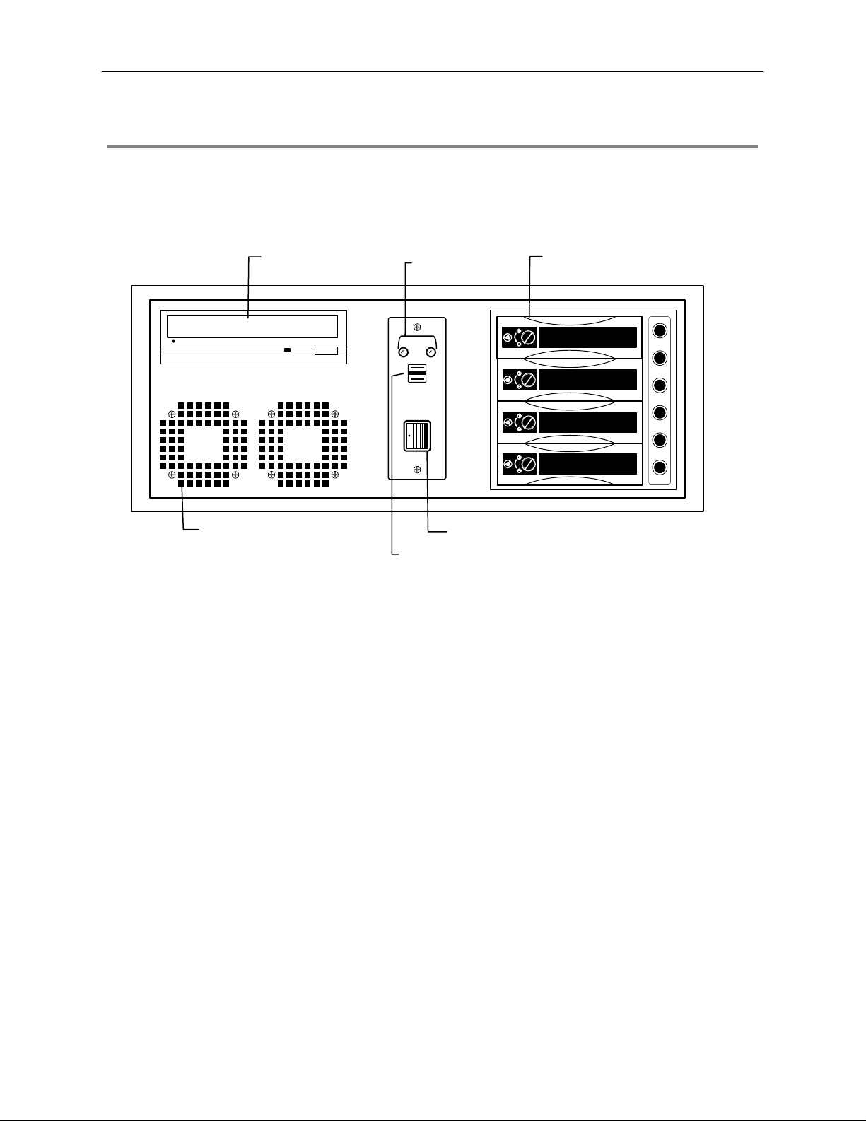
FRONT PANEL CONTROLS AND LEDS
The front panel of the NVS unit contains the d evices that will be commo nly used for data remov al, retrieval, and bac kup replacement.
The most common components and buttons are shown below.
21
DVD±RW Drive
Hard Drive Activity &
Hard Drive Array
Power LEDs
LOCK
OPEN
LOCK
OPEN
LOCK
OPEN
LOCK
OPEN
Cooling Fan Air Intake
On / Off Power Switch
USB Ports
Page 22
A
r
r
t
t
22
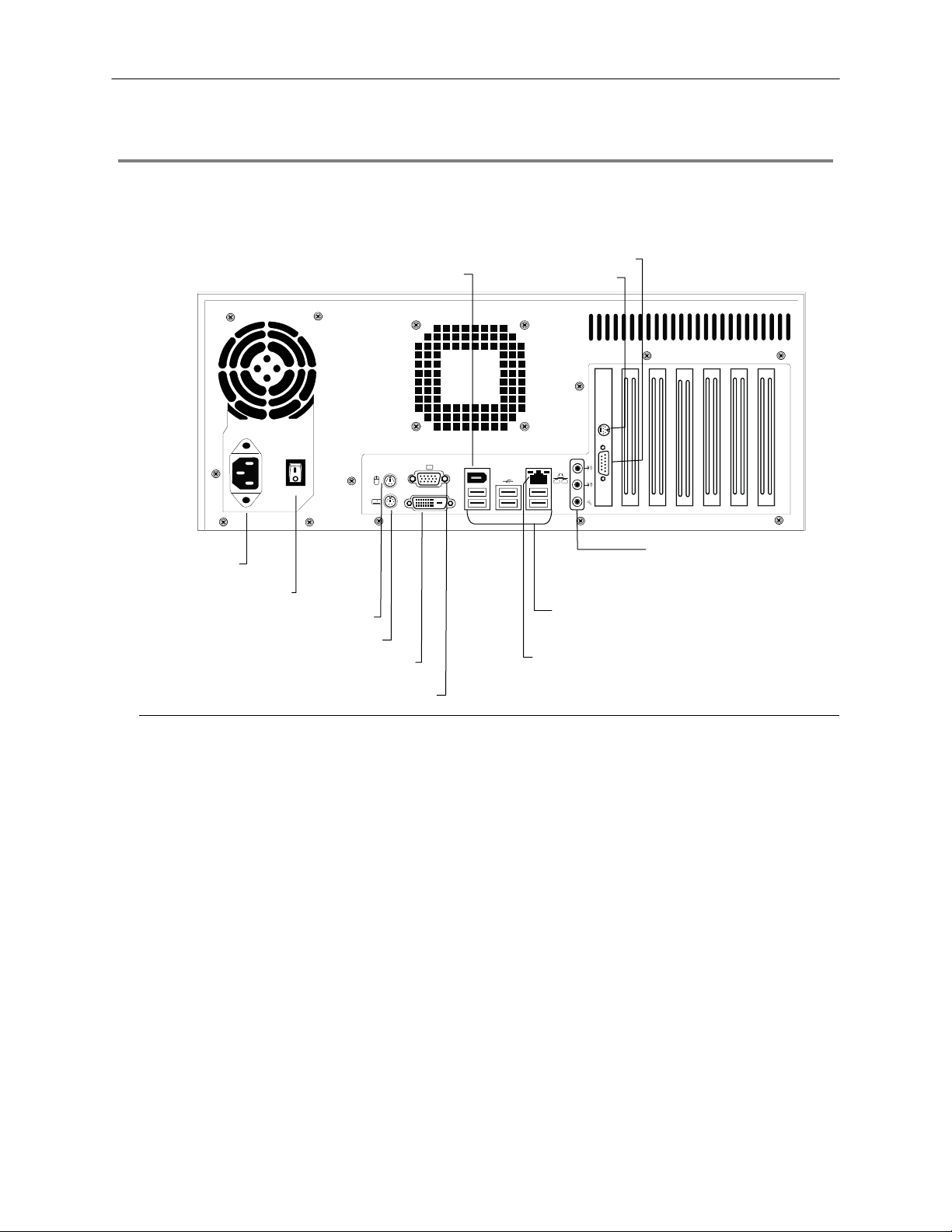
REAR PANEL CONNECTORS
The rear panel of the NVS unit contains virtually al l of the connectors y ou will be using. B elow is a diagram that outlines the location
and description of each connector:
SVGA Monitor Out
Fire Wire
1394
DVI-D
S-Video Out
C Powe
Connecto
Secondary Power Switch
PS/2 Mouse Inpu
PS/2 Keyboard Inpu
DVI-D Port
USB Ports
RJ-45 Network Jack
SVGA Output
Audio
• Line In
• Speaker Out
• Mic In
Page 23

GETTING STARTED
This chapter includes the following information:
• Included Components
• Setting up your NVS Hardware
• Optional Components
23
Page 24

R
a
X
X
X
X
X
24
IDENTIFYING INCLUDED COMPONENTS
Surveillix™ NVS systems come with a mo use, key board and se lected sof tware and cabl es. Identify th e followi ng components to mak e
sure everything has been properly inc luded with your new NVS unit. If any of th e following items are missing , contact your dealer to
arrange a replacement.
Included Components:
NVS Unit Mouse NVS Key
HVR/NV
Digital Video Recor
UserManu
HVR8-
model no.
HVR16HVR32-
NVR8-
NVR16-
Please carefully read these instructions before using this product.
Save this manual for future use.
1
Manual Repair CD Software Installation CD
Keyboard Rackmount Attachments with Screws Power Cable
Page 25

KEYBOARD SETUP
To attach the k eyboard to the DVR unit, plug the end of the Key b oard in to the keyboard PS/2 Port located on the back of the m achine.
The keyboard PS/2 Port can be identified by the purple color. Refer to the Rear Panel Connectors diagram for more information.
MOUSE SETUP
To attach the mouse to the DVR unit, p lug the end of the mo use into the mouse PS/2 Port located on the b ack of the machine. T he
mouse PS/2 Port can be identified by the green color. Refer to the Rear Panel Connectors diagram for more information.
The mouse uses a cursor. Cursors come in many different shapes but are most commonly shaped like an arrow.
Your mouse has two buttons: a left button and a right button. Quickly pressing and releasi ng one of these buttons is called cli cking.
Sometimes you will need to double-click – or click the same button twice quickly.
In this manual, click means to posit ion your mous e cursor on an icon and to s ingle click the le ft button. When a r ight click is required,
this is stated clearly. Double-click also refers to the left button.
The scroll wheel in between the two buttons is added to provide easier scrolling capability. By s imply mov ing the wheel with your index
finger, you can quickly move through multi ple pages, line, or windows . The wheel may also func tion as a third button al lowing you to
quickly click or double-click an icon or a selected item.
25
Scroll Wheel / Third Button
Right Button
Left Button
Page 26
26
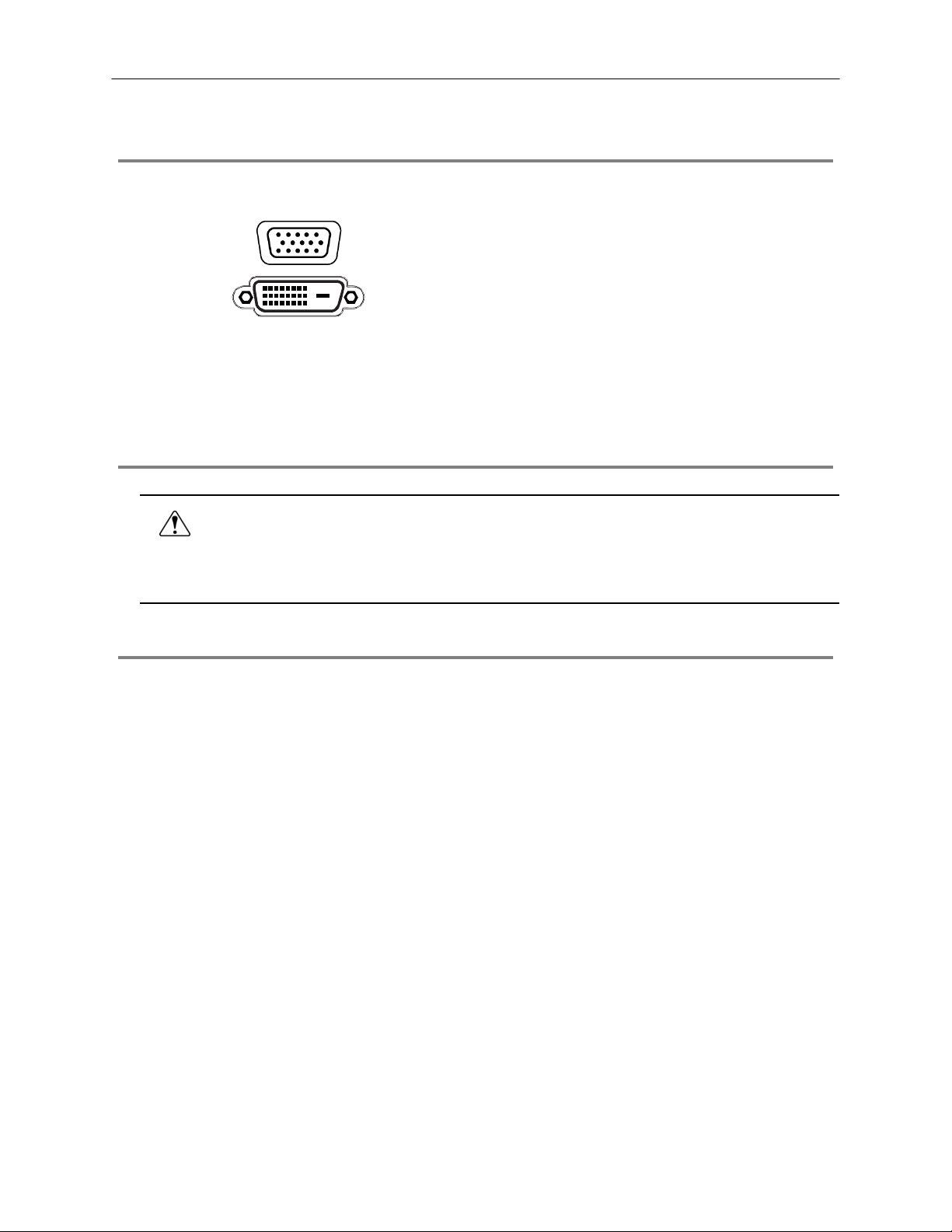
MONITOR SETUP
There are 2 available connections for monitors which can be used individually or in tandem.
SVGA Output To VGA Monitor.
Attach the moni tor or monitors to the rear of the NVR using the cable supplied by the monitor manufacturer. Refer to the monitor
manual for detailed information on how to setup and use it.
NOTE: The monitor must be capable of having a screen resolution of 1024 x 768 and display colors of at least 32 Bit
DVI-D Output To TV / Digital Monitor
POWER SETUP
Attach the AC power cable to the rear of the DVR Unit. See Rear Panel Connectors for more information.
WARNING: To reduce the risk of electrical shock or damage to the equipment:
• Do not disable the power grounding plug. The grounding plug is an important safety feature.
• Plug the power cord into a grounded (earthed) electrical outlet that is easily accessible at all times.
• Disconnect the power from the computer by unplugging the power cord either from the electrical outlet or the
computer.
CONNECTING A VIDEO SOURCE
The NVS, a Network Video Recor der has no vis ible video inputs because the NVS u nit connects and records only us ing IP / Networ k
video cameras. To connect video sources to the NVS unit, simply plug in a network cable to the NVS unit.
Page 27
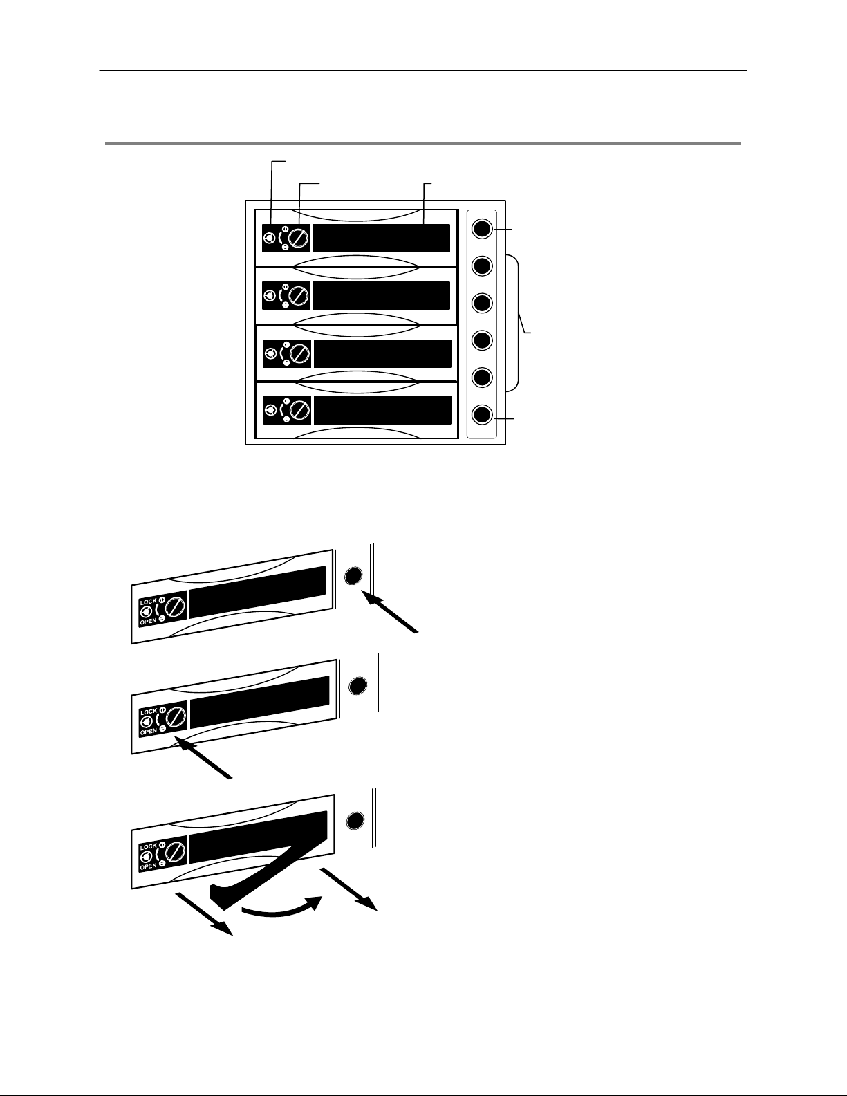
HARD DRIVE ARRAY
27
Handle Release
LOCK
OPEN
LOCK
OPEN
LOCK
OPEN
LOCK
OPEN
Release Handle Button Lock
Reset Button
Hard Drive
Power Buttons
Alarm Light
NOTE: The Alarm Light will turn on if the Hard Drives reach a temperature above safe operating conditions
Swapping a Hard Drive
1. Press the hard drive power button to turn off power to
the hard drive you wish to remove.
2. Turn the button lock to the open position and push the
handle release button.
3. Pull the lever outward while removing the hard drive.
Reverse steps to install.
Page 28

28
OPTIONAL COMPONENTS
To fully utilize the NVR’s potential; several optional Surveillix components are listed below. Contact the dealer for more information.
Extra Video Storage Hard Drive
Each DVR has a virtually unlimited storage p otential. A dd addition al Video Dat a Hard Drives to extend the amount of V ideo Data the
DVR system can store before overwriting older data.
UPS UPS Power Backup
UPS Power Backups allow your DVR to remain fully functional even in the ev ent of a power failure. UPS Power Back ups also even
the fluctuating power current out to provide a consistent, relia ble power flow. This creates a stable environment for the DVR and
reduces failure.
NP-4PKVM 4 Channel KVM Switch
The 4 Channel KVM s witch a llows you t o have multi ple boxes (up to 4) using on ly one k eyboard, mouse an d monitor. You ca n simpl y
switch between the DVRs using the keyboard.
Hot Swappable Redundant Power Supplies
Every DVR has the option o f a dual redundant hot swa ppable pow er supply . In the ev ent of a c omponent fa ilure the i noperable power
supply may be removed leaving the DVR running so no bre ak in recording occurs. Simply replace the p ower supply with a new one
and you are finished.
Raid Controller
A raid controller is available for increased performance or data reliability.
External RAID storage
An external RAID device is used for independent data reliability & provides much greater storage expandability
Gigibit NIC
Provides support for Dual Nic configurations
SCSI Interface adapter
Allows for external storage devices to be connected
Page 29

NVS BASICS
This chapter includes the following information:
• Registration and Upgrade
• Turning the DVR on and off
• Becoming familiar with the Display screen
• Defining Screen Divisions
29
Page 30

30
SETTING THE TIME AND DATE
1. Exit to Windows by clicking the Exit button from the Display screen and selecting Restart in Windows Mode. (See the Display
screen section later in this chapter)
2. Open Windows Explorer. Do this by right-clicking the My Computer Icon (located on the top left hand corner of the Desktop) and
select Explore.
3. Click on Control Panel to open it. If you do not see Control Panel listed, Click My Computer to expand the folder tree.
4. Double Click on Date and Time inside Control Panel.
5. Adjust the Date and Time.
6. When finished, close all open windows and restart the DVR. Do this by clicking the Start button (Located on the lower left hand
side of the Desktop) and selecting Shut Down
ACCESSING THE DVR UTILITY
Exporting DVR Settings
Exporting DVR settings can help configure multiple DVRs quick ly or reconfigure a unit that has failed. Some things must be k ept in
mind when using this feature.
You cannot use this function on:
1. Exit to Windows by clicking the Exit button on the Display screen then and select Restart in Windows Mode. (See the Display
2. Click Start > Programs > Surveillix > VFormat.
3. Click the Export button in the System Settings tool section.
4. Select a location to save the settings file and click Save.
5. Click the OK button to close the VFormat Utility.
• DVRs that are different models.
• When upgrading from certain software versions. (This feature cannot be used when upgrading from v2.x to v3.x)
screen section later in this chapter)
The DVR Utility will export the DVR settings and
automatically close.
Page 31

Importing DVR Settings
1. Exit to Windows by clicking the Exit button on the Display screen and selecting Restart in Windows Mode. (See the Display
screen section later in this chapter)
2. Click Start > Programs > Surveillix > VFormat.
3. Click the Import button in the System Settings Tool section.
4. Select the location of the settings file to import and click Open.
5. Click Yes to import the data file.
6. Click the OK button to close the VFormat Utility.
Changing Video Format
1. Exit to Windows by clicking the Exit button on the Display screen and selecting Restart in Windows Mode. (See the Display
screen section later in this chapter).
2. Click Start > Programs > Surveillix > VFormat.
3. Select the appropriate video setting from the list in the Video Setting Section – NTSC or PAL..
4. Click Set.
5. Click the OK button to close the VFormat Utility.
31
Page 32

32
DISPLAY SCREEN
Each time the DVR starts , the program defaults to the Display screen. T he following diagram outlines the buttons and features used
on the Display screen. You should bec ome familiar with these options a s this is the screen that will be displayed the majority of the
time.
Opens:
• Search Display
• Backup Center
• PTZ Controller
Opens Setup Display
Screen Division buttons
Current Date /
Time
Sensor Status
Relay Outputs
Live Camera Options
Right-click a camera on the Display screen to display these
options:
• Full Screen
• Instant Recording
• Search In Live
Open TV Out Options
Page 33

CAMERA VIEW
33
Recording Status
Special Recording Type
INSTANT
Camera No. and Name
Recording Status Indicator
The camera status for each camera is displayed in t he upper right corner on the Video Display Area. The follow ing are the different
states for each camera:
Recording Displayed when the camera is currently being recorded to the DVR.
Motion Detection Displayed when a camera (set up for motion detection) detects motion.
Display Displayed when the camera is currently not being recorded to the DVR.
Special Recording
There are two types of DVR Special Recording. Text is displayed on the camera indicating what type of Special Recording is
activated.
SENSOR Sensor is displayed when a sensor, associated with a given camera, is activated.
INSTANT Instant Recording is a manua l activ ation of th e r ecording f or t he selec ted camer a. Regar dle ss of the rec ordin g me thod ,
Instant Recording will start the camera recording and also flag the video for future searches using the Index Search
feature. INSTANT is displayed when a user ac tivates th e instant recordin g optio n. Double R ight-Click the video display
to activate and deactivate the Instant Recording option.
Page 34

34
SCREEN DIVISION BUTTONS
The Sc reen Division menu allows you to view camer as in groups such as two by two, three by three and four by four. The button
options are shown below.
1st Four Cameras View – Displays cameras 1-4 in t he Video Dis play Ar ea. To retur n to a different M ulti-Camera View,
select a different Screen Division option from the Screen Division menu.
2nd Four Cameras View – Displays cameras 5-8 in the Vide o Dis p lay Are a. To ret urn to a d ifferent Multi-Camera View,
select a different Screen Division option from the Screen Division menu.
3rd Four Cameras View – Displays cameras 9-12 in the Video Display Area. To return to a differe nt Multi-Camera
View, select a different Screen Division option from the Screen Division menu.
4th Four Cameras View – Displays cameras 13-16 in the Video Dis play Area. To return to a different Multi-Camera
View, select a different Screen Division option from the Screen Division menu.
1st Nine Cameras View – Displays cameras 1-9 in the Video Display Area. To r eturn to a different Multi-Camera View,
select a different Screen Division option from the Screen Division menu.
2nd Nine Camera View – Displays cameras 8-16 in the Video Display Area. To ret urn to a diff erent Mul ti-Ca mera View,
select a different Screen Division option from the Screen Division menu.
Multi-Camera View – Displays a group of cameras within the Video Display Area.
All Camera View – Displays all 16 cameras within the Vid eo Display Area.
Multi-Camera View – Displays a group of cameras within the Video Display Area.
Multi-Camera View – Displays a group of cameras within the Video Display Area.
Full Screen – The Full Screen Option allows you to view the Video Display Area using the entire viewa ble area on the
monitor. When this is selected, no menu options are visible. You can activate the Full Sc reen Option by c licking on the
Full Screen button within the Screen Division menu . You can deactivate Full Screen mode by right clicking on the
screen.
Auto Sequence – Sequences through the Screen Divisions sets. For example, selecting the 1A and then the Loop
button will sequence through 1A, 2A, 3A, 4A and th en repeat. This option is not available for the 7, 10 and 13 screen
divisions.
Page 35

SETUP OPTIONS
This chapter includes the following information:
• Setup Overview
• Camera Setup
• Motion
• Frame Setup
• Schedule
• Sensor
• Network
• Information
• Administrative
35
Page 36

36
SETUP OVERVIEW
The Setup options allow you to optimize your DVR by adjus ting things like camera names,
reboot schedules, recording schedules and more. It is extremely important that you setup
your DVR correctly for several reasons.
• Recording Schedules – By optimizing the recording schedule you can increase the
amount of pertinent recorded video that is saved on the DVR and keep it longer. You
can optimize the type of recording done by adding motion detection to this as well,
again increasing the amount of useful video.
• DVR Access – By setting up the access passwords you can tightly control the types
of access an individual may have. This ensures the security and integrity of the DVR.
• Camera Naming – By naming each camera you can easily identify the location and
any other pertinent information that may be helpful simply by viewing it on the Video
Display Area.
Page 37

play
CAMERA SETUP
Selected Camera
Dis
37
Define Camera Name
Select Camera Selects the camera to be edited.
Selected Camera Display Displays the live camera feed from the camera selected.
Sensor Connection Specify which sensors are currently in use.
Enable Network Device PTZ Enables setup and use of Network Camera and PTZ Functionality.
Setup Network Device Opens the Network Device Setup menu.
Registration Opens the Registration menu for entering Unlock Codes to activate the software.
Online Registration Opens the Online Registration menu for activating pre-registered software.
Camera Name Specify a name for each camera.
Page 38

A
r
38
NETWORK VIDEO
Connected Devices
Supported IP Camera Manufacturers
ACTi
Arecont Vision
Axis
Brans
D-Link
IQeye
Lumenera
Mobotix
Panasonic
Pixord
Samsung
Securgen
Sony
Stardot
Toshiba
VivoTek
Connecting a Network Device
Connecting Manually
1. From the Display scr een, clic k Setup.
2. Click Network Video.
3. Click the Add/Remove Device tab.
4. Select your network device from the Device Type list.
5. Type a Device Name.
6. Type the IP/URL address, Port, User ID and Password of the device.
7. Click Add.
utomatic Camera Finde
Page 39

Connecting with Camera Finder
1. From the Display scr een, clic k Setup.
2. Click the Network Video tab.
3. Click the Add/Remove Device tab.
4. Click Find Cameras to automatically find all connected Network cameras.
5. Select the check box next to the desired camera.
6. Click Get Device.
7. Type the User ID and Password of the device.
8. Click Update.
Assigning a Network Device to a Channel
1. From the Display scr een, clic k Setup.
2. Click Network Video.
3. Click the Channel Setup tab.
4. Click an available channel on the Channel List.
5. Type the desired Position Name.
6. Select the appropriate network device added previously.
7. If the device has PTZ capabilities, select the PTZ Camera check box to enable.
8. If supported, select the Use Network Camera Motion Detection check box.
9. Click Apply, then click Exit Setup.
39
Page 40

40
Camera Configuration
The Camera Configuration tab displays information on all cameras (analog and network) connected to the Surveillix DVR
Displaying More Columns
The Camera Configuration tab can be customized to display the information you use mo st. Click Select Column to add or remove
specific columns.
Capture FPS
Record FPS
Schedule
Manufacturer
Model
IP Address
Port Number
Resolution
Frame Rate
Codec
Quality
GOP
PTZ
Accessing the Configuration Menu
Use the Surveillix interface to access basic network device menu functions.
1. From the Display scr een, clic k Setup.
2. Click Network Video.
3. Click the Channel Setup tab.
4. Highlight the desired channel.
5. Click Setup Network Device.
Page 41

Upgrade and Registration
Have the following information available before registering.
Software Serial Number: That product Serial Number is the unique number that Toshiba provided with the purchase software.
System ID: The System ID is a number that is generated by the S urveillix unit. This is a unique code generated using the MAC
address of the computer running the software. The following steps illustrate how to obtain a unique System ID.
Locating the System ID
1. From the Display screen, click Setup.
2. Click Network Cameras.
41
3. Click the License tab.
4. Click Copy to copy the System ID.
Obtaining the Unlock Code
1. Open an Internet browser and go to: http://register.surveillixdvrsupport.com/
2. Type the Product Serial Number that was provided by Toshiba.
3. Type the System ID generated by the DVR.
4. Click Submit.
Page 42

42
5. Verify the information.
6. Click Next if the information provided is correct.
7. Once validated, the user will be provided with the Unlock Code.
8. Print the page and save for later reference.
Unlocking the Upgrade
1. Return to Setup > Network Cameras > License.
2. Enter the Unlock Code generated by the Surveillix Registration Site into the License Key box.
3. Click Register and confirm that the new License Key is listed in the Channel Connection License box.
4. Click OK.
Unlocking New Network Device
Follow the instructions above for registering the NVR upgrade to unlock any additional network devices.
Page 43

t
t
t
MOTION SETUP
The DVR allows the user to adjust several different Motion Settings and create motion detection areas.
Display full screen video
pop up on motion even
Beep on motion even
Display full screen video
pop up on sensor even
Schedule recording at a regular specified interval
43
Reduces Analog Signal Noise from Motion Detection
Create a Motion Area
1. Click Motion in Setup.
2. Select a camera from the Select Camera list.
3. Select the Detect Detail Motion Area check box.
4. Click Clear.
5. Click Advanced Motion Area Setup.
6. Click a Motion Detection Area shape button.
7. Drag the mouse over the camera image.
Note To create a polygon shape, click the mouse at each
point and double-click to close the shape.
8. Click OK.
9. Move the sliders to adjust motion sensitivity and the noise filter.
10. Define the pre-alarm and post-alarm recording time for a motion
event.
Pre Alarm – 0 > 50 Seconds [The number of seconds the DVR
records before motion is detected]
Post Alarm (MOTION) – 0 > 50 Seconds [The number of seconds
the DVR records after motion is detected]
Page 44

44
Activating an Alarm on a Motion Event
1. In the Motion Setup window, select a camera to edit from the Camera list.
2. Create a motion area.
3. Select the Alarm Output check box.
4. Select a Control Output to activate for the selected camera.
5. Select an Alarm Duration time when a motion event occurs.
Regular Interval Recording
Regular Interval Recording allows us ers to record a single fra me every few minutes or hours when there is n o motion. This opt ion is
only available when Motion recording or Sensor recording is selected in the recording schedule.
To enable Regular Interval Recording:
1. Select the Regular Interval Recording check box.
2. Specify how often to take an image when no motion is occurring. Users can go as little as one image per second.
Page 45

/
t
SCHEDULE SETUP
Recording Schedule
The Recording Sc hedule window allows the user to create different recording schedules based on th e d ay , time, and type of recording
desired. In addition, this window contains the System Restart options that allow the user to perform basic system maintenance by
automatically scheduling the DVR to restart periodically.
45
Recording Schedule Window
Recording Mode Options
Single Day Selection
Multi Day Selection
Emergency IP Setup
Open Restar
Setup Window
Create Special Day
Recording Schedules
Page 46

/
t
y
46
Sensor Schedule
The Sensors will supersede all other types of rec ording modes (Motion and Conti nuous). Regardless of the recordin g schedule of a
particular camera, if a sensor event occurs the associated cam eras will begin recording a s a Sensor Event. Sensor Rec ordings will
be flagged and searchable using the Index Search Mode. Cameras are associated to sensors in the Camera Setup menu.
Sensor Schedule Window
Alarm Options
Single Day Selection
Multi Day Selection
Emergency IP Setup
Open Restar
Setup Window
Create Special Da
Sensor Schedules
Page 47

Create a Recording Schedule
1. Select a day to begin creating the schedule fo r -or- click Single Day Selection, enabling Multi Day Selection, to create the
same schedule for multiple days.
2. Highlight the Time-Blocks within the Recording Schedule window for the camera(s) selected to schedule. Once the desired
Time-Blocks are highlighted, click a Recording Mode button. The Time-Blocks should now appear Blue for Motion, Yellow for
Continuous and White for No Recording.
Note Leave cameras recording with Sensor Detection set to No Recording for the specified time block(s).
Create a Sensor Schedule
1. Click Schedule and then and then select the Sensor option. Select a single day or click Single Day Selection to include
multiple days in the schedule.
2. Highlight the Time-Blocks within the Recording Schedule window for the sensor(s) to enable and schedule. Once the time
blocks are highlighted click Enable. The time block will now appear red.
Scheduling Alarm Events
There are three types of Alarm Events:
ALARM EVENT: This option logs the Alarm Events on the local server.
CENTRAL STATION: This option sends a Map Alarm to Central Station software such as SCS Multi-Site Management.
EMERGENCY AGENT: This option sends the Alarm Event to the Emergency Agent software.
Motion can be designated as an alarm eve nt. Often motion do es not need to be treated as an Alar m event. Ex: During work hours,
motion that occurs is expected and should not be treated as an alarm. However, after business hours, any motion that occurs could be
treated as an alarm.
1. Click Schedule on the Setup screen.
2. Select either Recording or Sensor.
3. Highlight time blocks in the schedule that have been set to Motion (or Sensor) and click the desired Event buttons (Alarm Event,
Central Station, Emergency Agent). A corresponding letter will display in the selected time blocks.
Emergency Agent Schedule
Video recording triggered by motion or sensor events can be sent to the Emergency Agent software.
1. Enable the Emergency Agent Event. (see Scheduling Alarm Events above).
2. Enter the IP Address of a PC running the Emergency Agent software under Emergency IP.
3. Select the check box next to the IP Address to enable it. Only one IP Address is supported at a time.
4. Enter the recording duration (in seconds) in the Emergency Time box.
Tip See the Emergency Agent chapter for detailed information on setting up the Emergency Agent software.
47
Page 48

r
48
Special Day Schedule
The user can create day s that have a unique recording schedule. If necessary create these on d ays that are ‘not typical’ such as
Holidays, Special Events, etc.
Special Day Mode / Normal Day Mode
Date Ba
Configured Special Days List
Creating/Editing a ‘Special Day’ Schedule
1. Click Normal Day Mode to enable the Special Day Mode.
2. Select a day by typing the date or clicking the arrow to the right of the Date Bar.
3. Highlight the time-blocks within the Recording Schedule window for the camera(s) selected. Once the desired Time-Blocks are
highlighted, click a Recording Mode button.
4. When finished creating the schedule the Save Special Day.
Note The special day should now appear as a date in the Special Day Schedule.
Deleting a ‘Special Day’ Schedule
1. Select a date from the Special Days list.
2. Click Delete Special Day.
Page 49

System Restart Setup
System Restart Setup allows the user to define a schedule wherein the DVR automatically restarts according to specified parameters.
49
Create System Restart Schedule
1. Click Schedule on the Setup screen.
2. Click Restart Setup.
3. Select the day(s) of the week to schedule an automatic system restart and select the check box to enable shut down.
Note This step alone does not trigger the DVR to restart, only to shut down.
4. Specify the time of day to schedule the system restart.
5. Select the Restart option.
Note If Off is selected, the DVR will shut down at the specified time but not restart.
Page 50

50
GENERAL SETUP
Adjust / Mute Volume
Function
Beep on Login Fail Enables the DVR to beep continuously in response to a failed login attempt. Only an aut horized login
will stop the beeping.
Sequence Setting Allows the video out picture to automatically cycle through channels at a set speed. Example: .Cycle
through channels 1-6 at four-second intervals.
Display Options
Use Full Screen Stretch the Surveillix interface to use the full monitor screen.
Display Size Select from available monitor display sizes. Use to correctly display video on wide screen monitors.
Voice Warning
The DVR allows users to play a sound file when either a Motion event or Sensor event occurs. This file c an be a custom created
sound file that is unique to the application. The selected WAV file is played through speakers attached to the DVR.
1. Click the Open Sound File icon to browse for a WAV file. The selected file will display in the box on the left.
2. Click the Test icon to verify the audio file.
3. Select Motion Event and/or Sensor Event to trigger the audio file.
Open Sound File
Test
Page 51

Connecting to a Wide Screen Display
1. Click Exit on the Display screen and select Exit in Windows Mode.
2. Right-click the Desktop and select Properties.
3. Click the Settings tab.
4. Drag the Screen Resolution bar to the proper resolution of the connected display.
Tip Refer to the display documentation for the proper resolution settings.
5. Click OK and confirm the change.
6. Double-click the Surveillix Server icon on the Desktop.
7. Click Setup on the Display screen and then click General.
8. Under Display Settings, select the Use Full Screen check box and then select the correct resolution from the Display Size list.
9. Click Apply.
Hybrid Sensor Setup
This interface is used to link Hard Contact Sensor Inputs from supported Network Devices to the DVR Software.
51
Volume
The volume control allows fine tuning of the volume settings on the DVR.
Volume Options:
• Slider Controls – Used to adjust the literal volume for the
respective devices listed.
• Mute Check Box – Select the mute check box to mute volume
on any of the device columns or select the Mute All check box to
mute all audio on the DVR.
Page 52

52
Auto Sequence Setting
Auto Sequenc ing i s av aila ble e ith er i n th e Dis p lay s c r een wh en Aut o Sequencing has been enabled or when a Spo t-Mo nitor out signal
is used to display on a spot monito r. Auto Sequencing conveniently displays video chann els at specified intervals and sequences
through each selected channel.
Screen Division Options
Enable Sequencing
Enable All Cameras
Select interval between
switching cameras
Custom Mode Create non-standard screen divisions
Skip 0 FPS Channel Sequence skips cameras with no video signal
Create Custom Auto Sequence
1. Open General setup and click Sequence Setting.
2. Click individual cameras in the left pane or click Select All to include all cameras in the sequence.
3. Select an Interval time (in seconds) to display each screen in the sequence.
4. Select screen division options for appropriate cameras.
Page 53

NETWORK SETUP
Network Setup allows the user to adjust settings such as Ports, setup emergency PPP information for use with the Emergency Agent
and enable Remote Access.
Settings for Video Sent to Remote Client
Use with
Emergency Agent
53
Use with Remote
Connections
Enable RS-232
Keyboards (PTZ)
Transport Rate A bandwidth throttle based on percentage of free network.
Web Viewer (iDVR) Enables/Disables access to the DVR using the Web Viewer interface.
Between DVR and Remote Client
Page 54

r
54
INFORMATION
The Information display allows users to define the site code nec essary for connecting to remote s oftware, save comments rela tive to
the DVR and store tech support and contact number information.
Total HDD /Available HDD Space
Enter comments
Current Serve
Software Version
User-Defined
Contact Numbers
Site Code A user-specified unique identific ation name used by other DVR software to identify the DVR. (Remote ,
Emergency Agent, SCS, Digital Signature Verifier)
Page 55

y
ADMINISTRATIVE SETUP
Select Date
Log Data Displa
55
Export Log Data (1 to 7 days)
Disk Management
The Disk Management window is a native Win dows func tion. This window dis plays th e partitio n schem e and hea lth status of the Ha rd
Disk Drives in the DVR. This window is often used to troubleshoot a DVR, or verify the amount of Hard Driv e storage installed. For
more information about Disk Management, consult a Windows XP manual.
Page 56

56
Setting Up DDNS
Dy namic Domain Name System (DDNS) is a service that provides a static address to simplify remote connection to the DVR. This
service is most useful for installations where the WAN (public) IP address is dynamic (changes from time to ti me). Most public IP
addresses are dynamic unless a static address has been specifically ordered from the internet service provider.
Enable DDNS
To enable this functionality of the DVR, follow the steps below:
1. Click Setup on the Display screen and log in as Administrator if prompted.
2. Click Administrative.
3. Click Program Management (Etc) and enter the Administrator password when prompted.
4. Click Show to the right of The agent program for DDNS.
5. Select the Enable DDNS check box.
6. Enter the ID, Password, and Hostname specified on the DDNS document shipped with your DVR.
Note Ensure the DVR has an IP address by setting it statically. The Network settings may need to be changed. If
you are not sure of the correct values, contact the individual or department responsible for network
administration at the site.
Set the IP Address
To set the IP address of the DVR, follow the steps below:
1. On the Display screen, click Exit and choose Restart in Windows Mode.
2. Right-click My Network Places and click Properties.
3. On the General tab, click Internet Protocol (TCP/IP) and then click Properties.
4. Select Use the following IP address.
5. Enter the following values (or as specified by the department responsible for network administration).
a. IP Address: The first three sets of numbers should match the router’s local IP address and the last set should be a unique
number between 1-254.
b. Subnet Mask: This should match the router’s setting (commonly 255.255.255.0 for 192.X addresses and 255.0.0.0 for 10.X
addresses).
c. Default Gateway: This is the router’s internal IP address. Once DDNS is configured, the router the DVR connects to will need
to be configured to forward ports 80 and 4000 to the IP address of the DVR.
For further instruction on this proc es s , vis it http://www.portforward.com/english/routers/port_forwarding/routerindex.htm
Select the correct model of router, and follow the ins tr uctions. Onc e DDNS and port f orwarding have be en c onfigure d, the DV R will b e
accessible from any remote site by entering th e HOSTNAME into the address bar of Internet Expl orer or the IP Address field in the
Remote Software.
Page 57

f
User Management
The User Management Console allows the administrator to create, edit, and delete user accounts. Each user account can be
assigned different privileges to limit the usage of th e DVR system. Users can be given administrator priv ileges by enabling all rights,
however only the true administrator account can log into the User Management Console.
Enable Auto Log Of
57
Log Off User after x Minute(s) of Inactivity*
Note The Delete User button immediately deletes the user – use cautiously.
Add a New User
1. From the Display screen, click Administrative.
2. Click User Management.
3. Click Add User to open the User window.
4. Enter a User Name and Password.
5. Enable appropriate Permissions.
6. Select Cameras and Audio channels to hide from the user.
7. Assign a User Rank.
8. Click OK to save changes and close the window.
*Auto Log Off affects all users
Page 58

58
User Rank
The User Ranking structure allows the option to assign a privilege system (1-10 where one has the most rights) to users of the DVR
Software. For example. Since only one us er is allowed to us e the PTZ controls at any one time, an administrator with a higher r ank
can kick another user out and take control of the PTZ.
The User Rank option affects:
SETUP ACCESS - The DVR Software can only have 1 user accessing Setup at any given time. A user with a higher rank will
kick another user out and then open Setup. NOTE: User settings will NOT be saved when a user with a higher ranking logs in.
PTZ CONTROL - The DVR SOFTWARE can only have 1 user using the PTZ controls at any given time. A user with a higher
rank will kick another user out and then open the PTZ controls.
1. From the Display screen, click Setup.
2. Click Administrative.
3. Click User Management.
4. Enter the Administrator password and click OK.
5. Select a user from the Select User box and click Update User.
6. Set the user’s rank using the User Rank list and click OK to save changes.
Changing the Administrator Password
1. Inside Administrative setup, click User Management. When the prompt appears, click Change Password.
2. Enter the new password and click OK.
Default Administrator Password
The default administrator login is:
User: Administrator
Password: <blank>
Log Management
The Log Management window provides the user the options to overwrite log files or schedule log deletion.
Setup Log Management Options
1. From the Administrative setup display click Log Management.
2. Select the check box to enable the Log File Overwrite Option.
Set Log Overwrite
a. Select Overwrite and define the size of the log file cache.
Set Log Cache Size
a. Select Do Not Overwrite and define the number of days to maintain log files.
Manually Delete Log Files
a. Select the type(s) of log file to delete. System Log, Event Log, Alarm Log.
b. Click Delete All.
3. Click OK to save the settings and close the window.
Page 59

Status Check / Email
General
1. Click Setup on the Display screen.
2. Click Administrative.
3. Click Status Check/Email.
4. Select the Enable Email Alarm check box.
5. Enter a From Name and e-mail Address.
Note This name and address will appear in the From line of the
email alert message.
6. Enter the SMTP information for the “From” email account. Contact the
email administrator for this information if necessary.
7. If using a secondary email account select the Use Secondary SMTP
check box and complete the SMTP information.
8. Click Test to check settings.
9. Click Apply when finished.
Users
1. Set up the General tab first.
2. Click the Users tab.
3. Select the type of Event to send email on.
4. Enter the User Name and E-mail Address of an email recipient.
5. Click Add.
6. Repeat for additional recipients and types of events.
Note A separate email notification for each type of event must
be set up for a single recipient to receive notifications for
each type of event.
59
7. Click Apply when finished.
Page 60

60
Storage Check
1. Set up the General and Users tabs first.
(see above)
2. Select the Use Storage Check check box.
3. Define the number of minutes.
4. Select an Alert Option, Beep or Popup Message, if desired.
5. Click Apply.
Recording Data Check
1. Setup the General and Users tabs first.
(see above)
2. Select the Recording Data Check check box.
3. Define the number of hours between data checks.
4. Select the Action Method.
5. Click Apply.
Page 61

SMART Information
The SMART Information tab displays Hard Drive information.
SMART Alert
1. Setup the General and Users tabs first.
(see above)
2. Select the Enable SMART Alarm.
3. Define the number hours between SMART checks.
4. Select the type of SMART event to trigger an action.
5. Define the maximum HDD temperature.
6. Select an action method.
7. Click Apply.
61
Alarm Event
1. Setup the General and Users tabs first.
(see above)
2. Select the Use Email Alarm check box.
3. Define the number of minutes between record ing data checks.
4. Select Motion and/or Sensor to send and alert on that type of event.
5. Click Apply.
6. Click Close to return to the Administration tab.
Page 62

62
INSTANT RECORDING
The Instant Recor din g featur e allow s users to ma nuall y initi ate r ecordi ng on a specific ca mera, overridi ng the current s ched ul e. When
Instant Recording is activated the DVR flags the clip as an event so Instant Recording instances can be found using the Index Search
Instant Recording can be used, for ex ample, when a suspicious object or person is detected and th e user wants to flag that sec tion o f
video for easy retrieval at a later date.
Activate Instant Recording
1. From the Display screen, double right-click the camera on which to enable instant recording. An INSTANT label will be placed on
the upper right corner of the video.
2. To turn the Instant Recording option off, double right-click the camera a second time.
Searching ‘Instant Recorded’ Video
1. From the Display screen click Search.
2. Click Index Search.
3. Select the Instant Recording option. See the Search chapter for more information.
Page 63

SEARCH
This chapter includes the following information:
• Search Overview
• Daylight Saving Time
• Index Search
• Preview Search
• Graphic Search
• Motion Search
63
Page 64

A
64
SEARCH OVERVIEW
The DVR has several options that a llow the user t o easily searc h through, and find, a particular sec tion of video. From Motion/Sensor
indexing to calendar views highlighting days with recorded vide o; the DVR is equipped to h elp the user quickl y find a specific video or
event.
The following chapter describes how to use the DVR Search features.
Screen Division buttons
Current Date/Time
Hour/Minute Control Bar
Calendar button
Play Controls
udio Channels
Playback Date/Time
Camera Select buttons
Note Audio Channel buttons are only viewable when one camera is selected.
Play Controls
Rewind
Back Frame
Stop
Play
Forward Frame
Back Frame Moves video back one frame
Rewind Rewinds video
Stop Stops video playback
Play Plays video
Forward Frame Moves video forward one frame
Page 65

Adjust the Brightness of an Image
1. Select an image to adjust by double-clicking on the desired image. Multiple images cannot be adjusted at one time.
2. Move the Brightness slide bar to the right or left to adjust the brightness.
3. Reset the Brightness by moving the slider back to the center of the bar.
Zooming in on an Image
1. Select an image to adjust by double-clicking on the desired image. Multiple images cannot be adjusted at one time.
2. Move the Zoom slide bar to the right or left to zoom in or out of an image.
3. Reset the Zoom by moving the slider back to its original position on the bar.
Zooming in on a Portion of an Image
1. Right-click the area of interest on the image and select Zoom.
- or – Double-right-click the image.
2. Repeat to zoom in further.
3. Continue clicking the right mouse butto n and the image zoom will cycle back to the original size.
Open Video from a Saved Location
Previously saved video clips or backup files can be searched for content. Find file by date and time or by name.
1. Click Open to search for the saved file.
2. Select a file from the list of saved clips and backup files or search by start hour.
3. Click OK to open the saved file.
Time Sync
The Time Sync option synchronizes a single cha nnel of video to playback in real time. Ordinarily the video may playback slower or
faster depending on several factors, including how many PPS recorded and number of cameras playing at the same time.
1. Select a single image to synchronize by double-clicking on an image.
2. Click Time Sync. The video will now playback in real time.
Clean Image
The DVR is capable of recording video using one of three different resol utions. When using the 720 x 480 resolution, two fiel ds are
mixed. Because of the timing gap between the two fields, ac cording to the standardiz ed image ru les, after i mage might occur to high
speed moving images. The Surveillix DVR allows the user to remove this by clicking the Clean Image button.
65
Page 66

66
PERFORMING A BASIC SEARCH
There are several different types of searches that can be perfor med on the DVR. The most basic involves selecting t he date, time,
camera, and clicking play.
1. Click the Calendar button to select a date.
2. Select a time by clicking the up and down arrows to the right of the time display.
3. Click OK.
4. Select one or more cameras.
5. Click Play. Video can be played forwards, backwards, or frame-by-frame.
PRINTING AN IMAGE
1. Using the Search screen, locate a frame to print.
Note Only one camera can be selected at a time for this function to work.
2. Click Print. A Print Options window appears. Depending on the printer being used, there may be several printing options
available. Refer to the printer manual for more information.
3. Click Print to print the selected images.
Note The message “NO DEFAULT PRINTERS INSTALLED” will display if no printer is installed.
DAYLIGHT SAVING TIME
The DVR automatically adjusts for Dayligh t Saving T ime c hanges. When the hour “ jumps forward” no v ideo is lost bec ause an hou r is
skipped. However when the hour “falls bac k” there is a duplicated hour that under normal circumstances would be r ecorded over.
The Surveillix DVR actually records both hours and allows the user to select which hour to play if the need arises.
To access the ‘lost hour’:
1. From the Search screen, click the Calendar button.
2. Select the date when Daylight Saving time ‘lost’ an hour. The Daylight Saving option
appears.
3. To play back the ‘lost hour’, select the Daylight Saving check box and enter the
repeated hour in the time box.
4. Click OK to confirm the date and begin playing the video using standard search
features.
Page 67

SAVE TO JPG OR AVI
The DVR can export single images in a JPG I mage file format and s ave video clips in a n AVI format. Both J PG and AVI file formats
are the most commonly used graphic al formats today. Virtually every computer offers some type of support for these file formats
which make them the most ideal formats to use.
JPG Optimized for compressing full-color or grayscale photographic images, J PG images are 24-bit (16.7 million color) gr aphics.
Use JPG to export a single image or frame.
AVI AVI image data can be stored uncompressed, but it is typically compressed using a Windows-supplied or third party
compression and decompression module called a codec. AVI is used to export a video clip.
1. From the Search screen, click Save.
2. Select the Export Type: Image File (JPG) or AVI File.
Note Different image format types provide different file-
sizes, quality and compatibility.
Image File
a. Select Quality (50>100). When size is not an issue, set the
quality to 100.
AVI File
a. Enter the duration (seconds) to record. Although 100 is the
longest time displayed, a longer recording may be entered
manually.
b. Select a Compression Codec. Each codec provides different
levels of quality, compatibility and file-size.
c. Select Quality - 50>100. When size is not an issue, set quality
to 100.
3. Click Export to save file. The Cancel button exits the window
without exporting file.
67
Page 68

68
Bookmarks
Use bookmarks to mark a video clip during a search. Export bookmarked data using the Clip Backup feature.
1. Perform a search for the desired video.
2. Stop playback at the beginning of the desired clip.
3. Right-click the video and select Start Bookmark.
4. Click the play button to continue playback.
5. Stop playback at the end of the desired clip.
6. Right-click the video at the desired end point and select End
Bookmark.
7. Type a name to identify the bookmark in the Title box.
8. Enter a memo or notes in the More Information box.
9. You may also select additional channels to include video at
different locations recorded at the same time.
10. Click Create.
Modify Bookmarks
You can modify a previously created bookmark to change the start or end time of the clip, add additional comments, change the title, or
add additional cameras.
1. From the Search screen, click Graphic Search and then
click Bookmark.
2. On the calendar, select the date the desired bookmarks were
created.
3. Select the desire d book m ark from the list.
4. Make the desire d c hang e.
5. Click Modify.
6. When the modification is complete, click Cancel to close the
window.
Page 69

Single Clip Backup
Alon g with the Save option, a single camera backup option is also include d with the Surveillix software. The single Camera or Clip
Backup allows the user to backup a single camera without hAVIng to backup multiple cameras at a given time. The Clip Backup option
gives the users the ability to choose a backup time frame, cho ose a specific camera, add memos, and even make a copy for the
Backup Viewer if needed.
1. From the Search screen, click Save.
2. Select the drive from the file tree to save data to. (Hard disk drive,
removable drive (USB), CD/DVD drive)
3. Select cameras from the list.
4. Define the Start and End time of the backup clip.
5. Select the Include Viewer check box to include a copy of the proprietary
Backup Viewer Software to view the clip on virtually any Windows
machine.
6. Click Add Memo to include additional information.
7. Click Backup to start the backup.
Note If backing up to a removable USB device click the Unplug
or Eject Hardware button after backup is complete to safely
remove the device.
Single Clip Backup Using Bookmark Data
1. From the Search screen, click the Save button.
2. Select the drive from the file tree to save data to. (Hard disk drive, removable drive, CD/DVD drive).
3. Click Use Bookmark Data.
4. On the calendar, select the date the desired bookmarks were created.
5. Select the desired bookmark from the list and click OK.
Note To include multiple bookmarks in a clip backup, select the
Multi Backup check box before selecting the desired
bookmarks.
69
6. Select the BV Copy check box to include a copy of the proprietary Backup
Viewer software to view the clip on virtually any Windows machine.
7. Click Add Memo to include additional information.
8. Click Backup to start the backup.
Note If backing up to a removable USB device click the Unplug or
Eject Hardware button after backup is complete to safely
remove the device.
Page 70

70
INDEX SEARCH
Using the Index Search can greatly decrease the amount o f time spent searching through saved video . The Index Search allows a
user to perform a search based on criteria such as Sensor, Motion and Instant Record events
Performing an Index Search
1. Click the Calendar button on the Search screen to select the date to search.
2. Click Index Search.
3. Select the cameras and sensors to include in the search.
4. Select the Select Time check box to define a specific period.
5. Select an event type to search (Sensor, Motion, Instant Record) or select the
All Event option.
6. Click OK. There may be a delay while results are returned. Results will be
displayed in a column on the left side of the screen – Each line represents a
segment of video. If no results are found, “NO IMAGE FOUND” will appear in
the column.
7. Once the results are displayed, double-click any one to play the associated
video.
8. Once the desired image is found, apply it to the Main Search by clicking the
Close button at the bottom of the results column.
Index Search Results Display
Image Display Area
Event Recorded on Camera #
Time Event Occurred
Event Type:
M – Motion
S – Sensor
I – Instant Record
Page 71

2 3
5 6
6
4 5 7
y (
PREVIEW SEARCH
Preview Search can be used in a number of circumstances to quickly find an exact moment where an event, such as a theft, occurred.
The Preview Search gives a 24 Hour visual overview of a sing le camera by separating a 24 hour period (1 day) into 24 i mages, one
image for each hour of the day. The search can then be further narrowed down into ten minute increments and one minute
increments by selecting one of the images displayed.
These example images show how the Preview Search functions.
The first screen that appears has 24 ima ges displayed. Each image rep resents the first second of each hour. If there is no image
recorded during that period then nothing will be displayed.
When an hour is selected (by double-clicking on the image), a new screen appears with 6 images. Each of these images represents a
10 minute segment of video within the selected hour.
Once a 10 minute segment is selected (by d ouble-clicking on th e image) the final sc reen appears which breaks down that 10 minute
segment into 1 minute increments (10 images).
1 Da
1 Hour Increments
24 Hours)
71
1 2
6
11
7
12
16 17
21 22
1
4
3
4
5
1098
15
14
13
18 19 20
23 24
1 Minute Increments
1
2
3
8
9
10
10 Minute Increments
1 Hour
10 Minutes
1 Minute Increments
Page 72

72
Performing a Preview Search
1. Select a single camera by either turning off all cameras but one or double-clicking a displayed image.
2. Click Preview Search. 24 images display. If there is no recorded video during a portion of the day, “No Image” will be displayed
where the image should be.
3. Refine the search by double-clicking on an image to select it. 6 images display. If needed, return to the previous 24-image view
by right-clicking on an image.
4. Refine the search by double-clicking on an image to select it. 10 images display. If needed, return to the previous 6-image view
by right-clicking on an image.
5. Double-click an image to select the 1-minute segment of video to play. A single image displays. If needed, return to the
previous 10-image view by right-clicking on an image.
6. Use the Play controls to play the video of the selected segment.
7. To exit out of the Preview search with the current image still selected, click Preview Search again to clear it.
GRAPHIC SEARCH
The Graphic Search option displays video in graph format.
Hours 0-23 (24 hours)
Cameras
Recording Block
Performing a Graphic Search
1. Click Graphic Search and then click Recording Status on the Search screen.
2. Click the calendar icon to select a day.
3. Click on an area of the blue recording block. Only one camera can be displayed at a time.
4. Recorded video from the corresponding camera and time block will display above.
5. Use the mouse or arrow buttons to move through recording blocks and view video.
Page 73

OBJECT SEARCH
Objec t Search is a powerful search utility that is used to search a region on t he video for any motion changes. Results are neatly
displayed and can be viewed quickly.
73
Performing an Object Search
1. Perform a Basic Search. See the instructions on Performing a Basic Search.
2. Select a single camera, either by turning off all cameras but one or by double-clicking a displayed image.
3. Click Object Search on the Search screen.
4. Click and drag the mouse on the video display to define a motion region area. Resize by pulling on the small square boxes
located on the outer perimeter of the area.
5. Click Start Search, the Object Search Filter Information
window will open
6. Select an End date/time. One hour is the default setting.
7. Adjust the sensitivity if necessary.
8. Click OK.
9. Select a motion event from the search results list displayed
on the right
10. Click Apply to Main Search to display the selected image
in the main Search screen and to use play controls
11. To start a new object search using the original image, click
Reload First Frame.
12. To exit Object Search without selecting an image, click
Cancel.
Page 74
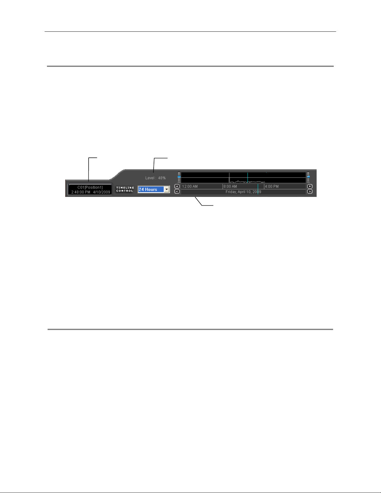
74
MOTION SEARCH
The Motion Search provides a dynamic display of the levels of motion in recorded video. A djus t th e lev el of motion to only play clips of
video at or above that level.
Tip To enable motion data to be saved for Motion search, ensure that you select the following settings:
On the Motion setup page under Motion Regions, select the Detect Detail Motion Area check box.
On the General setup page under Display, select the Motion Detect on Continuous Recording check box.
Note Motion Search is only available for newly recorded video; it is not compatible with video recorded prior to
version 3.6.
Motion Tolerance Level Camera Information
Timeline
Performing a Motion Search
1. From the Search screen select a camera. Motion Search can only be performed on one camera at a time.
2. Click Graphic Search and then click Motion Search.
3. Click the calendar icon to select a day.
4. Adjust the motion level line.
5. Adjust the timeline display settings.
6. Click the play button to start playback.
Tip You can drag the blue line on the Timeline or motion level box to adjust the time.
AUDIO PLAYBACK
Audio is played back at 48,000Hz.
To play audio with the video:
1. Select a single camera by turning off all cameras but one using the Camera Select buttons. The audio buttons will be displayed.
2. Select a single audio channel to play. When an audio channel is selected, the Time Sync button will be automatically selected.
3. Click Play.
Page 75

SEARCH IN LIVE
The Search in Live feature allows users to review events i mmediately while monitoring live video. Pause, rewind, and resume l ive
video within seconds of an alarm event or suspicious activity.
75
1. Move the mouse cursor over the desired live video display on the Live Display screen.
2. Press the scroll button on the mouse.
3. The search in live Controls will display at the bottom of the
image.
4. Use the controls to pause, rewind, move frame-by-frame or
resume playing as desired.
Page 76

76
NOTES:
Page 77

BACKING UP VIDEO DATA
This chapter includes the following information:
• Overview
• Saving Video to a DVD
• Saving Video from a Single Camera
• Scheduling Regular Video Backup
77
Page 78

78
BACKUP OVERVIEW
The Backup Center allows you to back up record ed video data from multiple dates and times to one or mo re locations including t he
DVD-RW drive, Network Storage Locations, and External Hard Drives.
The DVR can easily backup im portant v ideo data t o an inter nal or extern al media locat ion. The most comm only us ed forms of t his are
CD-R/RWs, External USB or FireWire Hard Drives, and Network Drives. Every DVR comes equipped with a DVD-RW drive, USB port,
and Network Adapter.
The DVR is capable of performing a backup to multiple CD/DVDs when the f ile sizes exceed the capacity of a single dis k. You may
also specify multiple locations for backup as well as the order they are recorded to.
The DVR backs up video data using a proprietary compression format that can only be read by the DVR Backup Program. This
ensures the integrity of the data.
Throughout the backup process the DVR will c ontinue recording without interru ption. This is the result of t he tremendous mult iplexing
power of the DVR, which allows it to perform virtually all functions without disrupting the recording process.
Nero® Express
The DVR uses Windows® XP® Embedded running Nero® Express 7.0 to write data to the DVD-RW Drive. This solution allows the DVR
software to read and write data to the DVD-RW Drive without formatting the disk first.
CAUTION: Although many features are available within Nero, it is highly recomm ended that you do NOT
use any features other than those necessary for the standard backup of video data as outlined in this
section, loss of information or software instability may result.
Page 79

r
General Screen Overview
The General Backup Sc reen is use d for perf orming bulk backup of v ideo recorded by all c ameras for a selected period, or periods, to
a specified storage location.
Calenda
79
Select Additional Drive/Folder
Define Drive Priority
Select Remote Network Location
Hour / Minutes Recording data displays in hourly (24 horizontal columns) and 10-minute ( 6 vertical cells) segments.
Green cells indicate time with recorded video. Red cells indicate time selected for backup.
Backup Status Displays the size of all video currently selected for backup, the available size of the media currently
selected for backup to, and the dates and times of video currently selected for backup.
Fixed HDD
Display all Hard Drives
Performing a General Backup
1. Click Backup on the Display screen.
2. Select the date or dates to back up using the calendar. Dates highlighted in blue contain recorded data.
3. Select the blocks of time to back up using the Hour/Minute grid. Blocks of time with recorded video are highlighted in green.
Blocks of time selected for backup are h ig hlighted in red.
4. Select the backup drive or drives under Select Backup Media, or click Network Drive, or Browse. When selecting the CD-RW
Drive you must specify the number of CDs to use for backup.
5. Click Backup Order to set the backup order.
6. Select the Include Viewer check box to include the Backup Viewer Application.
7. Click Start Backup to begin the backup process. A progress bar will be displayed in the lower right corner of the Display screen.
Page 80

80
Clip Screen Overview
The Clip Screen is used for backing up video recorded by individual camer as for a selected period of time to a specified storage
location
Performing a Clip Backup
1. Click Backup on the Display screen.
2. Click the Clip tab at the top of the Backup Center window.
3. Set the Start Time and End Time under Time Setup.
4. Select the cameras to back up in the Channel Selection box.
5. Select the Backup Drive to save the backup video to.
6. Select the Include Viewer check box to include the Backup Viewer Application.
7. Enter pertinent clip information into the Clip Information section in the Description box.
8. Click Backup to begin the backup process. A progress bar will be displayed in the lower right corner of the Display screen.
Page 81

Scheduled Screen Overview
The Scheduled Backup Screen is used for performing bulk backup of video recorded by all cameras for a selected period, on a regular
scheduled basis (1-24 hours). The Scheduled Backup Screen is similar to the General Backup Screen.
Performing a Scheduled Backup
1. Click Backup on the Display screen.
2. Click the Schedule tab at the top of the Backup Center window.
3. Select the blocks of time to back up using the Hour/Minute Grid. Blocks of time with recorded video are highlighted in green.
Blocks of time selected for backup are h ig hlighted in red.
4. Set the Backup Time to perform the backup.
5. Set the Repeat Backup Time to specify the number of hours between backup procedures (between 1 and 24 hours).
6. Select the Backup Drive to save the backup video to using the Select Backup Media menu or the Network Drive button. To
save to a local drive or partition you must first rename the location “Backup”.
7. Check the Overwrite on Disk Full check box to overwrite previous scheduled backups when the disk becomes full.
8. Click Save Backup Setting to save the current backup setting and return to the Display screen.
Specifying Scheduled Backup Drives
In order to use the Scheduled Backup feature one or more stor age drives or partitions connected to the DV R must be labeled as a
backup drive.
1. Exit and restart in Windows mode.
2. Double click the My Computer icon on the DVR desktop. A file menu will
be displayed.
3. Right click on the drive to specify as a backup drive for Scheduled
Backup and click Rename. Rename the drive to ‘Backup’. Repeat this
process for all drives to use for Scheduled Backup. To remove a drive
from use for Scheduled Backup, change its name to something other
than ‘Backup’.
4. Restart the application and return to the Schedule tab in the Backup
Center window.
81
Page 82

82
NOTES:
Page 83

LAN / ISDN / PSTN CONNECTIONS
This chapter includes the following information:
• Overview
• Configuring TCP/IP Settings
• Connecting to a LAN
• LAN / ISDN / PSTN Connections
83
Page 84

84
LAN OVERVIEW
The DVR can be easily connected to a Local Area Network (LAN) and uses Microsoft’s® powerful and secure Windows® XP
Embedded operating system. This allows for easy and well-documented instructions on setting up LAN connections no matter what
type of LAN you want to use.
A LAN is a group of computers and other devices dispersed over a relatively limited area and connected by a communications link that
allows one device to interact with any other on the network.
There are many reasons why using Microsoft® Windows® XP Embedded is superior to ot her platforms when running o n a LAN. The
number one reason is security. Windows XP Embedded is based on NT technology, wh ich, historically has boasted the most r eliable
and secure Operating System in the world. Runnin g the DVR on a secure network is important to prevent unwanted users from
gaining access to confidential infor mation. Unwanted users can compromise the integrit y of the confidential data being stored and
viewed, and in extreme circumstances can cause irreparable damage to the network.
Since connecting the DVR to a network c an be extremely complex (dep ending on the network), this Surveillix DVR manual wil l cover
only the basics. It is suggested that the DVR admi nistrator consult the Vendor or IT Administrator before attempting to create or
connect to a LAN.
CONNECTING TO A LAN USING TCP/IP
The networking options of the DVR can create and edit a ll Network settings available on Windows XP Emb edded. The DVR comes
equipped with a 10/100 Network Interface Card (NIC). This card uses a standard RJ-45 connector.
Configuring TCP/IP Settings
1. On the Display screen, click Exit and select Restart in Windows Mode.
2. Right-click the My Network Places ic on locat ed on the desktop and select Properties.
3. Right-click Local Area Connections and select Properties.
4. Select the Internet Protocol (TCP/IP) by clicking on it once. Once it is highlighted, click Properties.
5. Select Use the Following IP Address option. Enter the IP Address and Subnet mask appropriate for the network. It is
recommended to contact the Network Administrator for appropriate IP settings.
Example: a. Common IP addresses are 10.0.0.25
b. Common Subnet masks are 255.255.2 55.0
Note In order to connect to the DVR through a remote LAN connection, a static IP address must be assigned. If
the network assigns the IP address automatically (DHCP), contact the Network Administrator for help
assigning a static IP address.
6. If the network requires you to specify the DNS information, enter it now by selecting the appropriate DNS options.
7. When finished configuring the TCP/IP settings click OK to close the Internet Protocol (TCP/IP) Properties window.
8. Click OK to close the Local Area Connection Properties window.
9. It may be required to restart Windows for the changes to take effect. Restart windows by clicking START on the desktop and
clicking Restart.
Page 85

WEB VIEWER
This chapter includes the following information:
• Overview
• Configuring the Web Viewer
85
Page 86

86
WEB VIEWER OVERVIEW
The DVR allows you to access video using Microsoft® Internet Explorer® 7.
Highlights:
View Live Video from most computers
Username and Password protected
Easy to use graphical interface
Basics:
75 users can acces s the Web DVR simultaneously. The Web Viewer is an easy, secure way to view liv e video from virtually any
computer with an internet connection using Microsoft Internet Explorer.
In order to log in to the DVR server, a user ac count must be made for the user. This ensures that only authorized personnel ar e
allowed to log in. In addition, each user can be assigned different privileges that allow them or deny them access to different
functions. For example, a user can be granted access to only view cameras 4, 8 and 16.
Screen Division buttons
Activate Commands
Enable/Disable Camera Display
Page 87

Configuring the Server for Remote Connection
1. Click Setup on the main display screen.
2. Click Network.
3. Clear the Disable Remote Control check box. You should now be allowed to adjust port settings if necessary.
NOTE: If you are using a Firewall, it may be necessary to adjust th e port settings on both the DVR and the Firewall. Contac t the
Network Administrator for more information.
4. Select the Web Viewer (iDVR) check box.
5. Click Apply.
6. Make sure a User account is created. Without a user account, the Administrator account must be used.
7. The DVR server is now ready to receive incoming connections.
Connecting to a DVR Using Web Viewer
1. Open Microsoft Internet Explorer.
2. Enter the IP address of the DVR into the Address Bar.
3. When attempting this for the first time on a computer a window will open and you will be asked to accept an Active X installation.
Select Yes to this.
NOTE: If you receive a message saying Internet Explorer® security settings do not allow you to downloa d Active X
components then you will need to adjust t he browser security s ettings. One way to d o this is to add the IP addr ess of the DVR to the
trusted sites list inside Internet Explorer® settings. Contact the System administrator for additional help with adjusting Internet
Explorer® settings.
4. When the Web Viewer finishes loading, select one or more cameras (or select a screen division button).
5. Click GO!
6. A login window will appear. Enter the Username and Password of an authorized user.
7. The cameras will display.
Closing the Web Viewer
To exit the Web Viewer close Internet Explorer.
87
Page 88

88
Page 89

INCLUDED SOFTWARE SETUP
This chapter includes the following information:
• Emergency Agent Overview
• Remote Software Overview
• Digital Verifier
• Backup Viewer
89
Page 90

90
EMERGENCY AGENT OVERVIEW
The Emergency Agent software is a util ity that streams video across a Local Area Ne twork to a Client PC when an al arm is detected
on the DVR. The video that streams across can be stopped, played forwards and backwards, in slow motion or real speed.
The utility is loaded at startup and placed in the taskbar. It constantly monit ors for a signal from the DVR. When an alarm signal is
detected the Emergency Agent Image Viewer window opens and starts playing the video from the camera associated to the alarm.
Configuring the DVR
To enable the Emergency Agent on the DVR follow these steps:
1. Enter Setup and confirm you are in the Camera Setup menu.
2. Select a camera and then associate sensor(s) to that camera using the Sensor Connection check boxes.
3. Click the Network Setup button and make sure that Disable Remote Control is cleared.
Note The Emergency Agent uses one port to transfer the data through (the Emergency Port). The port can be
adjusted inside the Network Setting menu if necessary. It is recommended that the default setting should be
used unless the port must be changed.
4. Click the Schedule Setup button. Enter the IP Address of the computer
running the Emergency agent software.
5. Click the box next to the IP Address to enable it.
6. Select the Sensor radio button.
7. Create a schedule for the appropriate sensor
8. Click Apply.
Configuring the Client PC
All configurations take place in the Emerg ency Agent window on the Client PC for descriptions and locations of the buttons and
features of the Emergency Agent window refer to the Emergency Agent window section later in this chapter.
1. Open the Emergency Agent window on the Client PC - Start >All Programs > Surveillix > Emergency Agent > Emergency Agent
2. Right Click in the DVR list and select New. Enter the DVR Code,
DVR Name, and IP Address of the DVR to connect to in the Site Edit
window that opens. Click OK
3. Click the Options menu and select Setup.
4. Confirm that the Network Port in the Setup window is set to the same
number as the Emergency Port in Network Settings on the DVR. If
the numbers are different adjust the Network Port on the client PC to
match the DVR.
5. Click the OK button
6. Restart the Client PC
Page 91

t
y
Setup Window
Network Port Indicates the port which the Emergency
Agent uses to listen for incoming events.
This number should be changed to t he sam e
number as is set in the Emergency Port in
Network Settings on the DVR.
Save Directory Sets the location that recorded video footage
is saved to.
Notice Options Configuration settings for activating an
audible indicator or popup window when the
Emergency Agent receives an event.
91
EMERGENCY AGENT WINDOW
Video Displa
DVR Lis
Event Level
Event Type
Zoom Thumbnails
Event List
Edit Memo
Save Memo
Level Buttons
Memo Text Box
Filter Event List
1. Select a DVR from the DVR List in the Filter Options section.
2. Select the Date to include.
3. Select the type of Events to include.
4. Select the event levels (Review, Dismiss, Critical, Default).
5. Click the On button to display filtered event listings.
Page 92

92
Add Items to Alarm Confirm List
1. From the Option menu, click Setup.
2. Type the desired text in the box below the Alarm Confirmation List.
NOTE: The items in the Alarm Confirmation List will be available on a list under Status Setting in main Emergency Agent screen.
3. Click Add.
4. Click OK to save changes and close the window.
Page 93

y
SEARCH ALARM WINDOW
Video Displa
Play Controls
Go to Next Event
Go to Previous Event
Alarm Event Information
Export Quality It may be necess ary to reduce the overall size of an AVI file; for example, to email to someone .
AVI file sizes can be reduced by r educing the i mage quali ty. However , reducing t he image quality
causes the AVI video to appear more pixilate d. When s ize is not an issue, s etting qua lity to 10 0 is
highly recommended.
Digital Signature Adds a digital signature to the ex ported JPG image for use with the Digital Signature Verifi er to
verify integrity of exported images and prevent tampering.
View Recorded Video
1. Double-click an event listing to open the Search Alarm window.
2. Use the play controls to locate the desired video.
3. Select the Continue Playing check box to watch all recorded events. When cleared, playback stops at the end of the alarm
event.
4. Select the Same Camera check box to watch all events recorded by a single camera.
5. Click Apply after making any changes.
Export Video
1. Double-click an event listing to open the Search Alarm window.
2. Use the play controls to locate the desired video.
3. Click the Rewind button to return to the beginning or desired spot in the video.
4. Click the Stop button.
5. Select the Export Option – JPG or AVI.
Save JPG:
a. Select the Digital Signature check box to embed a digital signature in a JPG file.
b. Click the Export button.
Save AVI
a. Reduce Export Quality only if necessary to reduce the size of the file.
b. Click the Export button.
93
Page 94

94
REMOTE SOFTWARE OVERVIEW
The DVR was specifically designe d to be fully operated and maintained remotely. It connects using the standard TCP/IP pr otocol
thorough connection types such as DSL, Cable Mod e, T1, ISDN, 56K M ode m, LAN, and more. The Surveillix Remote software al lows
you to view live video, search through archiv ed video, export images and video clips a nd have virtually full Setup control. Sur veillix
Remote Software is Microsoft Vista
Highlights:
Search archived video
View live video
Export images and video clips
Control relay outputs
Setup administration
Basics:
The DVR can have up to 5 simultaneous remote connections. Each user can perform f unctions on the DVR and will not aff ect the
other users. The only exceptions to this are accessing Setup a nd controll ing a PTZ camera. Only one user is allowed to acc ess setup
or control a PTZ camera at any given time. The pictures per s econd passed to the Remote Client vary greatly depending on the
connection type and speed.
In order to log in to the DVR server, a user ac count must be made for the user. This ensures that only authorized personnel ar e
allowed to log in. In addition, each user can be assigned different privileges that allow them or deny them access to different
functions. For example, a user can be denied Searching and Setup privileges and only granted access to view cameras 4, 8 and 16.
®
compatible.
It is highly recommended that users not be granted Setup priv ileges since this can pose a security risk.
Only properly authorized Administrators should have access to Setup.
The Remote software operates virtually the sa me way as the DVR itself. The appeara nce of it matches the DVR almost identi cally;
however, there are a few minor differences. Some searc h features are not availa ble (suc h as the Ind ex and Object Searc hes) as well
as some Setup options.
Page 95

Remote Software Setup
Installing Remote Software
1. On the client computer, insert the Surveillix Software CD into the CD-ROM. The CD should play automatically.
2. When prompted, select the Install Remote Software option. Follow the installation instructions carefully.
3. When the software finishes installing, close any open installation windows.
Create a New Remote Connection
DVR Site List
95
Selected Site Information
1. Select Start > Programs > Surveillix > Remote > Surveillix Remote Center. The Surveillix Remote Software opens and the
Local Connection window opens.
2. Click New to open the Site Info window.
3. Select the Site Type and enter a Site Name. The Site Name will be the name displayed inside the connection box to help
identify the unit.
4. Enter the IP Address of the DVR server. By default the DVR is set to connect using DHCP.
5. Enter the Center Port. This setting is specified on the server.
6. Click OK.
7. Click on the newly created connection and enter the login username and password. (case sensitive)
8. Click Connect.
Import/Export saved configurations
Page 96

96
Configuring the DVR
In order to access the DVR remotely, the DVR Server must be setup to allow remote connections.
Time Out Value Specifies a value (in seconds) to wait for a signal
from the Surveillix Remote Client. If a signal is not
received by that time, the connection is dropped.
Center Port Used to transfer the connection data.
Image Port Used to transfer the image data.
Search Port Used to transfer the search data.
Configuring the Server for Remote Connection
1. Enter Setup on the DVR.
2. Click Network to open the Network menu.
3. Clear the Disable Remote Control check box. You should now be allowed to adjust port settings if necessary.
Note If you are using a Firewall, it may be necessary to adjust the port settings on both the DVR and the Firewall.
Contact the Network Administrator for more information.
4. Click OK.
5. Make sure a user account is created (See Creating a New User in the Setup Section). Without a user account, the Administrator
account must be used.
6. The DVR server is now ready to receive incoming connections.
Page 97

DIGITAL VERIFIER OVERVIEW
JPG images and AVI video files that are exported from the Digital Video Recorder are automatically embedded with a digital signature.
Digital Signatures are a way to verify the authenticity of the images to ensure that they have not been ta mpered with or edited in any
way. Included on the Software Installation DVD s uppli ed with the DVR is t he Digita l Sign atur e Verific ation program. T his pr ogr am can
be installed on any computer and loads an image in question.
Installing the Digital Verifier
1. Insert the Software Installation CD into the CD-ROM. (Do not install on the DVR.)
2. Select the Digital Verifier option to begin installation.
3. When the Welcome screen appears, click Next.
4. When the Setup Complete window appears click Finish. Installation is complete.
Using the Digital Verifier
1. Open the Digital Verification program by selecting Start > Programs > Surveillix > Digital Verifier > Digital Signature Verifier.
2. Click the Browse button to load the JPG image.
3. Enter the Site Code of the DVR that the image was
originally extracted from. (The Site Code is specified in the
Information Setup menu)
4. Click Verify to continue or Close to close the window
without verifying.
97
If the image has not been tampered with, a blue square will
appear around the image with the message “Original image file.”
If the image has been tampered with, a red square will appear
around the image with the message “Entire image c hanged or
wrong SITE CODE.”
Page 98

98
BACKUP VIEWER OVERVIEW
The Backup Viewer al lows you to play back the exported video in its proprietary format. Video saved in this format is extremely
difficult to tamper with and therefore is the ideal solution when law enforcement and the legal department are involved.
This video cannot be read by any other viewer.
The Backup Viewer operates essentially like the Search portion of the DVR software.
For detailed explanations of these functions, refer to the chapter on Search Options in this manual.
Installing Backup Viewer
1. Insert the Software Installation DVD into the DVD-ROM.
(Do not install on the DVR.)
2. Select the Backup Viewer opti on to begin ins tallation.
When the Welcome screen opens, click Next.
3. Read the License Agreement and selec t the appropria te radio button to accept the terms of the license agreement.
Click Next.
4. Select Yes to install the POS component or select No for a basic install.
Click Next.
Note The POS component is only necessary when connecting to a server running the POS Upgrade.
5. When the Choose Destination Location window opens click Next.
This will install Backup Viewer in the default destination folder.
6. Select the shortcuts to install, or clear all boxes for no shortcuts.
Click Next.
7. When the InstallShield Wizard Complete window appears click Finish.
Setup is now complete.
Loading Video from DVD or Hard Drive
1. Open the Backup Viewer program: Start > Programs >
Surveillix > Backup Viewer > Backup Viewer.
2. Click Open. The Total Backup Search window will open.
a. For DVD-ROM data, select the appropriate DVD-ROM drive
letter from the Backup Media box.
b. For hard drive data, select either an attached hard drive from
the Backup Media box or select the Open Folder icon to
browse to a specific directory.
Note Once selected, available video data will be
displayed in the Choose Start Hour box.
3. Click on the desired time to select it.
4. Click OK. The video will now load into the Backup Viewer.
Page 99

SCS OVERVIEW
SCS software is Network DVR Ma nagement Software; a powerful utility that allows 100 or mor e DVRs to be controlled using one
computer. This software allows you to view live video , search saved vid eo, edit and configure s etup on each DVR, and import maps
of buildings and other locations.
The SCS software was specifically designed as an enterprise software solution.
Highlights:
View Live Video from most computers
Username and Password protected
Easy to use graphical interface
Basics:
In order t o log in to the DVR server, a user account must be made for each user. This ens ures that only authorized personnel are
allowed to log in. In addition, each user can be assigned different privileges that allow them or deny them access to different
functions.
Configuring the Server for Remote Connection
1. Enter Setup on the DVR.
2. Click the Network Setup Button.
3. Uncheck the Disable Remote Control option. You should now be allowed to adjust port settings if necessary.
NOTE: If you are using a Firewall, it may be necessary to adjust th e port settings on both the DVR and the Firewall. Contac t the
Network Administrator for more information.
4. Click OK.
5. Make sure a user account is created. Without a user account, the Administrator account must be used.
6. The DVR server is now ready to receive incoming connections.
Connecting to a DVR
Refer to the Setup section of the SCS Manual for information on using the SCS Software.
99
Page 100

100
 Loading...