

Page 1
ADJUSTABLE SPEED DRIVES
nC1 Drive
Page 2
Ultra-Compact
Sub-Micro Drive
The nC1 is a sub-micro, or nano-sized drive with a full range of features to meet the
needs of nearly any user. The nC1 is designed to be a simple drop in replacement for a
starter on an existing project or as a new installation. Either way, the nC1’s small size
and full featured design make it a perfect choice for your application.
An Easy Choice
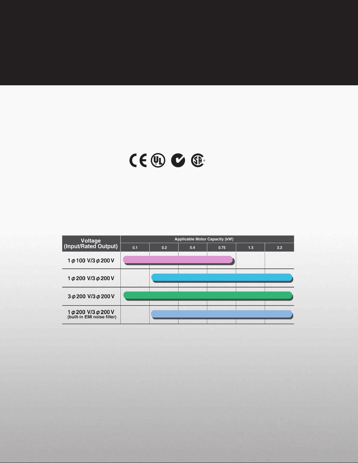
The nC1 drive comes with either single-phase or three-phase input with input voltage
ratings as low as 120 V. This makes it an excellent choice for small OEM applications.
The single-phase input means that the nC1 can be used in applications that were
previously too cost-prohibitive to install a three-phase drive. All nC1’s have a threephase 230 V output.
Models and Applicable Motors
Simple to Install
The nC1 is designed to be a drop-in replacement for a starter. The terminal
arrangements for input and output power are even set up like a starter. Side-byside mounting and the unit’s vertical construction allow for a smaller footprint.
The nC1 provides better control of your application, more protection for your motor,
and more room in your cabinet.
Page 3

Easy-to-Use
Easy To Program
The nC1 uses a simple, straightforward programming menu for quick and
easy setup of the drive. There are no complicated sub menus or “hidden”
parameters. By using the built-in programming wizards, the nC1 can be
programmed for simple operations with the push of a button. Available
Windows® programming software makes it a snap to set up the drive.
User-Friendly Operation
The nC1 comes ready to run. Simply mount the drive, run your power
connections and you are ready for operation. Many operations require
no programming whatsoever. The user-friendly interface is designed to
set the speed and start/stop functions of the unit easily. The drive will also
operate from nearly any standard industrial control inputs.
Array of Communications
In today’s fast-paced manufacturing world, coordinated systems require
communications from drive-to-drive and drive-to-system. A built-in port and a
variety of option cards give you versatility in communication selection.
• Built-In RS232/RS485 Port
• Communication Protocol Options
- Ethernet TCP/IP
- Ethernet IP
- DeviceNet
- Modbus RTU
- Modbus Plus
- Johnson Controls Metasys N2
- Probus DP
Page 4

nC1 Drive
Full-Scale
Display
Displays the operating frequency,
parameter information, a monitored
item, the cause of a failure,
and so on.
PROGRAM Lamp
Lights when the inverter is in
parameter setting mode. This lamp
blinks when the parameter “AUH”
or “Gr.U” is selected.
UP Key
Pressing the up key when lamp is
on allows the operating frequency
to be seen.
Input
Terminals
CHARGE Lamp
Indicates that high voltage is still
present within the inverter. Do not
open the cover while this is lit.
MONITOR Key
Displays operating frequencies,
parameter, and error messages.
RUN Lamp
Lights when an ON command
is issued but no frequency signal
is sent out. It blinks when operation
is started.
DOWN Key
Pressing the down key when lamp
is on allows the operating frequency
to be seen.
Built-In
Potentionmenter
Output
Terminals
STOP Key
Pressing of the STOP key while
the RUN key lamp is on will cause
a slowdown-stop.
ENTER Key
Page 5

Standard Specifications
nC1 ASD Standard Specifications
Model Range
1001P-1007P
2002P-2022P
2001PL-2022PL
2002P-2022P
Input Voltage Rating
120 V / Single Phase
230 V / Single Phase
230 V / Three Phase
230 V / Single Phase with
RFI / EMI Filter
KW Range
0.1 - 0.75 KW
0.2 - 2.2 KW
0.1 - 2.2 KW
0.2 - 2.2 KW
HP Range
1/8 - 1 HP
1/4 - 3 HP
1/8 - 3 HP
1/4 - 3 HP
Overload Rating
150% for 60 seconds
Input Voltage Tolerance
+10%, -15%
+10%, -15%
+10%, -15%
+10%, -15%
Input Frequency Rating
50 / 60 Hz
50 / 60 Hz
50 / 60 Hz
50 / 60 Hz
Input Frequency Tolerance
± 5%
±5%
±5%
±5%
Output Voltage Rating
230 V, Three Phase
Color
Munsel 5Y8 / 0.5
Control System
Sinusoidal PWM Control
Output Voltage Range
Adjustable within a range of 100 to 120% of the corrected supply voltage (200 V), nonadjustable to any voltage higher than the input voltage
Output Frequency Range
0.5 - 200 Hz, Default Setting: 0.5 - 80 Hz, Max Frequency: 30 - 200 Hz
Minimum Frequency Step
0.1 Hz: Operation Panel Setting, 0.2 Hz: Analog Input (when the Max Frequency is 100 Hz)
Digital Setting: within ±0.5% of the Max Frequency (-10 to +50°C)
Frequency Accuracy
Analog Setting: within ±1.0% of the Max Frequency (25°C ± 10°C )
V/f Characteristics
V/f, Slip Frequency Compensation, Base Frequency, Base Frequency Voltage and Torque Boost (adjustable amount)
Frequency Setting Signal
Internal Pot on the Front Panel, External Frequency Signal (connectable to a volume with a rated impedance of 3 -10 kΩ), VI Terminal (Input Impedance: 42 kΩ
(Voltage: 0 - 10 Vdc) or 250Ω (Current: 4 - 20 mAdc)). The frequency can be set arbitrarily using a two point setting.
Start-up & Jump Frequency
Adjustable within a range of 0.5 - 10 Hz, up to 1 frequency can be adjusted together with its widths
PWM Carrier Frequency
Selectable from among 2, 4, 8, 12 and 16 kHz (Standard Default Setting: 12 kHz or 4 kHz for models with a Built-In EMI Noise Filter)
Accel / Decel Time
Two selectable Accel / Decel Times adjustable from 0.1 to 3000 seconds
Retry Operation
Selectable number of retries (maximum 10 times); If the protection function is activated, the retry function restarts on completion of a check of the main circuit.
Electric Control
Charging of Capacitor (Deceleration Time can be shortened by activating Forced Shortened Deceleration mode.)
Dynamic Braking
Braking Start Frequency: 0 to Max Frequency, Braking Rate: 0 to 100%, Braking Time: 0 to 20 seconds
Input Terminal Functions
Forward / Reverse Run Input Signal, Jog Run Input Signal, Standby Signal, Preset-Speed Operation Input Signal, Reset Input Signal, etc.
Output Terminal Functions
Frequency Lower Limit Output Signal, Frequency Upper Limit Output Signal, Low-Speed Detection Output Signal, Specified Speed Attainment Output Signal, etc.,
Open Collector, RY Output
Failure Detection Signal
1 Form C contact, Rated: 250 Vac, 2A, cosØ = 0.4
FM / AM Output
PWM Output: (1 mAdc full-scale DC ammeter or 7.5 Vdc full-scale DC ammeter / Rectifier-type AC Voltmeter, 225% Current Max 1 mAdc, 7.5 Vdc full-scale)
Protective Function
Stall Prevention, Current Limitation, Overcurrent, Output Short Circuit, Overvoltage, Overvoltage Limitation, Undervoltage, Ground Fault, Power Supply Phase
Failure, Output Phase Failure Overload Protection by Electronic Thermal Function, Armature Overload at Start-up, Load-Side Overtorque at Start-up, Overheating
Prevention, Detection of Analog Signal Break
Momentary Power Failure Protection
Auto-Restart Control after momentary power failure
Electronic Thermal Characteristics
Switching between Standard Motor / Constant- Torque VF Motor, Overload Trip, Overload Stall Selection
Frequency: Inverter Output Frequency
Alarm: Stall Alarm "C," Overvoltage Alarm "P," Overload Alarm "L," Overheat Alarm "H."
Status: Inverter Status (Frequency, Cause of Activation of Protective Function, Input / Output Voltage, Output Current, etc.) and Parameter Settings
4-Digit, 7-Segment LED
Free-Unit Display: Arbitrary Unit (e.g. Rotating Speed) Corresponding to Output Frequency
Indicator
Lamps indicating the inverter status by lighting, such as RUN lamp and PRG lamp
Use Environments
Indoor- Altitude: 1000 m (maximum), not exposed to direct sunlight, corrosive gas, explosive gas or vibration (less than 5.9m 2) (10 to 55 Hz)
Ambient Temperature
-10 to +50˚C
Storage Temperature
-20 to +65˚C
Relative Humidity
20 to 93% Non-Condensing
nC1 ASD Standard Specifications
Model Range 1001P-1007 P 2002P-2022P 2001PL-2022PL 2002P-2022P
Input Voltage Rating 120 V/Single Phase 230 V/Single Phase 230 V/Three Phase
KW Range 0.1 to 0.75 KW 0.2 to 2.2 KW 0.1 to 2.2 KW 0.2 to 2.2 KW
HP Range 1/8 to 1 HP 1/4 to 3 HP 1/8 to 3 HP 1/4 to 3 HP
Overload Rating 150% for 60 Seconds
Input Voltage Tolerance +10%, -15% +10%, -15% +10%, -15% +10%, -15%
Input Frequency Rating 50/60 Hz 50/60 Hz 50/60 Hz 50/60 Hz
Input Frequency Tolerance ± 5% ±5% ±5% ±5%
Output Voltage Rating 230 V, Three Phase
Color Munsel 5Y8 / 0.5
Control System Sinusoidal PWM Control
Output Voltage Range
Output Frequency Range 0.5 to 200 Hz, Default Setting: 0.5 to 80 Hz, Max Frequency: 30 to 200 Hz
Minimum Frequency Step 0.1 Hz: Operation Panel Setting, 0.2 Hz: Analog Input (when the Max Frequency is 100 Hz)
Frequency Accuracy
V/f Characteristics V/f, Slip Frequency Compensation, Base Frequency, Base Frequency Voltage and Torque Boost (Adjustable Amount)
Frequency Setting Signal
Startup & Jump Frequency Adjustable within a Range of 0.5 to 10 Hz; Up to 1 Frequency can be Adjusted Together with its Widths
PWM Carrier Frequency Selectable from among 2, 4, 8, 12, and 16 kHz (Standard Default Setting: 12 kHz or 4 kHz for Models with a Built-In EMI Noise Filter)
Accel/Decel Time Two Selectable Accel/Decel Times Adjustable from 0.1 to 3000 seconds
Retry Operation Selectable Number of Retries (Maximum 10 Times); If Protection Function is activated, Retry Function restarts after a main circuit check.
Electric Control Charging of Capacitor (Deceleration Time can be Shortened by Activating Forced Shortened Deceleration Mode)
Dynamic Braking Braking Start Frequency: 0 to Max Frequency; Braking Rate: 0 to 100%; Braking Time: 0 to 20 seconds
Input Terminal Functions Forward/Reverse Run Input Signal, Jog Run Input Signal, Standby Signal, Preset-Speed Operation Input Signal, Reset Input Signal, etc.
Output Terminal Functions
Failure Detection Signal 1 Form C Contact, Rated: 250 Vac, 2A, cosØ = 0.4
FM/AM Output
Protective Function
Momentary Power Failure Protection Auto-Restart Control after Momentary Power Failure
Electronic Thermal Characteristics Switching between Standard Motor/Constant- Torque VF Motor, Overload Trip, Overload Stall Selection
4-Digit, 7-Segment LED
Indicator Lamps Indicate Inverter Status by Lighting, such as RUN Lamp and PROGRAM Lamp
Use Environments
Ambient Temperature -10 to +50˚C
Storage Temperature -20 to +65˚C
Relative Humidity 20 to 93% Non-Condensing
VOLTAGE HP MODEL NUMBER FLA HEIGHT WIDTH DEPTH WEIGHT
110 V
Single Phase
230 V
Single Phase
230 V
Three Phase
230 V
Single Phase
Built-in RFI / EMI Filter
Adjustable within a Range of 100 to 120% of Corrected Supply Voltage (200 V), Nonadjustable to any Voltage Higher than the Input
Voltage
Digital Setting: within ±0.5% of the Max Frequency (-10 to +50°C)
Analog Setting: within ±1.0% of the Max Frequency (25°C ± 10°C )
Internal Pot on the Front Panel, External Frequency Signal (Connectable to a Volume with a Rated Impedance of 3 to 10 kΩ),
VI Terminal (Input Impedance: 42 kΩ (Voltage: 0 to 10 Vdc) or 250 Ω (Current: 4 to 20 mAdc)). Frequency can be Set Arbitrarily
Using a Two Point Setting
Frequency Lower Limit Output Signal, Frequency Upper Limit Output Signal, Low-Speed Detection Output Signal, Specified Speed
Attainment Output Signal, etc., Open Collector, RY Output
PWM Output: (1 mAdc Full-Scale DC Ammeter or 7.5 Vdc Full-Scale DC Ammeter/Rectifier-Type AC Voltmeter, 225% Current Max
1 mAdc, 7.5 Vdc Full-Scale)
Stall Prevention, Current Limitation, Overcurrent, Output Short Circuit, Overvoltage, Overvoltage Limitation, Undervoltage, Ground Fault,
Power Supply Phase Failure, Output Phase Failure Overload Protection by Electronic Thermal Function, Armature Overload at Startup,
Load-Side Overtorque at Startup, Overheating Prevention, Detection of Analog Signal Break
Frequency: Inverter Output Frequency
Alarm: Stall Alarm “C,” Overvoltage Alarm “P,” Overload Alarm “L,” Overheat Alarm “H.”
Status: Inverter Status (Frequency, Cause of Activation of Protective Function, Input / Output Voltage, Output Current, etc.) and Parameter
Settings
Free-Unit Display: Arbitrary Unit (e.g. Rotating Speed) Corresponding to Output Frequency
Indoor-Altitude: 1000 Meters (Maximum), not Exposed to Direct Sunlight, Corrosive Gas, Explosive Gas or Vibration (Less than 5.9 m2)
(10 to 55 Hz)
Model FLA & Approximate Dimensions (Inches) & Weight (Lbs)
0.12 VFNC1S-1001P 0.7 5.6 2.8 3.9 2.2
0.25 VFNC1S-1002P 1.4 5.6 2.8 3.9 2.2
0.5 VFNC1S-1004P 2.4 5.6 2.8 3.9 2.2
1.0 VFNC1S-1007P 4.0 5.6 4.6 4.9 2.2
0.25 VFNC1S-2002P 1.4 5.6 2.8 3.9 2.2
0.5 VFNC1S-2004P 2.4 5.6 2.8 4.9 2.2
1.0 VFNC1S-2007P 4.0 5.6 2.8 5.4 2.2
2.0 VFNC1S-2015P 7.5 5.6 4.6 6.1 3.3
3.0 VFNC1S-2022P 10 5.6 4.6 6.1 3.3
0.12 VFNC1-2001P 0.7 5.6 2.8 3.9 2.2
0.25 VFNC1-2002P 1.4 5.6 2.8 3.9 2.2
0.5 VFNC1-2004P 2.4 5.6 2.8 4.9 2.2
1.0 VFNC1-2007P 4.0 5.6 2.8 5.4 2.2
2.0 VFNC1-2015P 7.5 5.6 4.6 6.1 3.3
3.0 VFNC1-2022P 10 5.6 4.6 6.1 3.3
0.25 VFNC1S-2002PL 1.2 5.6 2.8 3.9 2.2
0.5 VFNC1S-2004PL 2.3 5.6 2.8 4.9 2.2
1.0 VFNC1S-2007PL 4.0 5.6 2.8 5.4 2.2
2.0 VFNC1S-2015PL 7.5 5.6 4.6 6.1 3.3
3.0 VFNC1S-2022PL 10.7 5.6 4.6 6.1 3.3
230 V/Single Phase with
RFI / EMI Filter
Page 6

North America Headquarters & Manufacturing Facilities (Houston, TX)
TOSHIBA — Quality by Design
Toshiba's culture and history are strongly rooted in quality. Our designs are
technologically innovative, and our products are manufactured from start to
end using only the highest quality domestic and foreign parts.
Product Warranty
Toshiba offers a comprehensive warranty program on its full line of industrial
products. Consult your salesperson or the factory for specific information.
Medium Voltage Motor
G7 Drive
Need to Know More?
Be sure to visit our website located at www.toshiba.com/ind for the latest
information on Toshiba products and services.
Customer Support Services
Toshiba offers 24-hour service nationwide. For assistance of any type
call: 1-800-231-1412.
ADJUSTABLE SPEED DRIVES MOTORS CONTROLS UPS INSTRUMENTATION PLC
Available Through:
INDUSTRIAL DIVISION
13131 West Little York Road, Houston, Texas 77041
Tel 713/466-0277 Fax 713/466-8773
US 800/231-1412 Canada 800/872-2192 Mexico 01/800/527-1204
www.toshiba.com/ind
Copyright 8/2007
*NC1brocct070815*
 Loading...