

Page 1

Toshiba Personal Computer
NB250/NB255
Maintenance Manual
TOSHIBA CORPORATION
Page 2

Copyright
© 2010 by Toshiba Corporation. All rights reserved. Under the copyright laws, this manual
cannot be reproduced in any form without the prior written permission of Toshiba. No
patent liability is assumed with respect to the use of the information contained herein.
Toshiba Personal Computer NB250/NB255 Maintenance Manual
First edition April.2010
Disclaimer
The information presented in this manual has been reviewed and validated for accuracy.
The included set of instructions and descriptions are accurate for the Satellite Series at the
time of this manual's production. However, succeeding computers and manuals are subject
to change without notice. Therefore, Toshiba assumes no liability for damages incurred
directly or indirectly from errors, omissions, or discrepancies between any succeeding
product and this manual.
Trademarks
IBM is a registered trademark, and OS/2 and PS/2 are trademarks of IBM Corporation.
Microsoft, MS-DOS, Windows, DirectSound and DirectMusic are registered trademarks of
Microsoft Corporation.
Intel and Pentium are registered trademarks, and SpeedStep is a trademark of Intel
Corporation.
Sound Blaster is a registered trademark of Creative Technology Ltd.
Centronics is a registered trademark of Centronics Data Computer Corporation.
Photo CD is a trademark of Eastman Kodak.
All other properties are trademarks or registered trademarks of their respective holders.
Page 3
Preface
This maintenance manual describes how to perform hardware service maintenance for the
Toshiba Personal Computer Satellite, referred to as the Satellite Series in this manual.
The procedures described in this manual are intended to help service technicians isolate
faulty Field Replaceable Units (FRUs) and replace them in the field.
SAFETY PRECAUTIONS
Four types of m
essages are used in this manual to bring important information to your
attention. Each of these messages will be italicized and identified as shown below.
DANGER: “Danger” indicates the existence of a hazard that could result in death or
serious bodily injury if the safety instruction is not observed.
WARNING: “Warning” indicates the existence of a hazard that could result in bodily
injury if the safety instruction is not observed.
CAUTION: “Caution” indicates the existence of a hazard that could result in property
damage if the safety instruction is not observed.
NOTE: “Note” contains general information that relates to your safe maintenance
service.
Improper repair of the computer may result in safety hazards. Toshiba requires service
technicians and authorized dealers or service providers to ensure the following safety
precautions are adhered to strictly.
Be sure to fasten screws securely with the right screwdriver. If a screw is not fully
fastened, it could come loose, creating a danger of a short circuit, which could cause
overheating, smoke or fire.
If you replace the battery pack or RTC battery, be sure to use only the same model
battery or an equivalent battery recommended by Toshiba. Installation of the wrong
battery can cause the battery to explode.
NB250/NB255 Series Maintenance Manual iii
Page 4

The manual is divided into the following parts:
Chapter 1 Hardware Overview describes the Satellite Series system unit and
each FRU.
Chapter 2 Troubleshooting Procedures explains how to diagnose and resolve
FRU problems.
Chapter 3 Test and Diagnostics describes how to perform test and diagnostic
operations for maintenance service.
Chapter 4 Replacement Procedures describes the removal and replacement of
the FRUs.
Appendices The appendices describe the following:
Handling the LCD module
Board layout
Pin assignments
Keyboard scan/character codes
Key layout
Screw torque list
Reliability
Conventions
This manual uses the following formats to describe, identify, and highlight terms and
operating procedures.
Acronyms
On the first appearance and whenever necessary for clarification, acronym
s are enclosed in
parentheses following their definition. For example:
Read Only Memory (ROM)
Keys
Keys are used in the text to describe m
any operations. The key top symbol as it appears on
the keyboard is printed in boldface type.
Key operation
NB250/NB255 Series Maintenance Manual iv
Page 5

Some operations require you to simultaneously use two or more keys. We identify such
operations by the key top symbols separated by a plus (+) sign. For example, Ctrl + Pause
(Break) means you must hold down Ctrl and at the same time press Pause (Break). If
three keys are used, hold down the first two and at the same time press the third.
User input
Text that you are instructed to type in is shown in the boldface type below:
DISKCOPY A: B:
The display
Text generated by the computer that appears on its display is presented in the typeface
below:
Format complete
System transferred
NB250/NB255 Series Maintenance Manual v
Page 6

Table of Contents
Chapter 1 Hardware Overview
1.1 Features .............................................................................Error! Bookmark not defined.
1.2 2.5-inch HDD....................................................................Error! Bookmark not defined.
1.3 Power Supply ....................................................................Error! Bookmark not defined.
1.4 Batteries............................................................................. Error! Bookmark not defined.
1.4.1 Main Battery.......................................................Error! Bookmark not defined.
1.4.2 Battery Charging Control ...................................Error! Bookmark not defined.
1.4.3 RTC Battery........................................................ Error! Bookmark not defined.
Chapter 2 Troubleshooting Procedures
2.1 Troubleshooting Introduction................................................ Error! Bookmark not defined.
2.2 Troubleshooting Flowchart................................................... Error! Bookmark not defined.
2.3 Power Supply Troubleshooting.............................................Error! Bookmark not defined.
2.4 Display Troubleshooting.......................................................Error! Bookmark not defined.
2.5 Keyboard Troubleshooting ...................................................Error! Bookmark not defined.
2.5 External USB Devices Troubleshooting............................... Error! Bookmark not defined.
2.6 TouchPad Troubleshooting ................................................... Error! Bookmark not defined.
2.7 Speaker Troubleshooting.......................................................Error! Bookmark not defined.
2.6 Wireless LAN Troubleshooting ............................................ Error! Bookmark not defined.
2.7 Camera Troubleshooting.......................................................Error! Bookmark not defined.
2.8 Bluetooth Troubleshooting ...................................................Error! Bookmark not defined.
2.9 2in1 card Troubleshooting.................................................... Error! Bookmark not defined.
2.12 HDD/SSD Troubleshooting ................................................Error! Bookmark not defined.
2.13 CRT Troubleshooting.......................................................... Error! Bookmark not defined.
2.14 LAN Troubleshooting ......................................................... Error! Bookmark not defined.
2.17 3G Troubleshooting............................................................ Error! Bookmark not defined.
NB250/NB255 Series Maintenance Manual vi
Page 7

Chapter 3 Tests and Diagnostics
3.1 The Diagnostic Test.............................................................Error! Bookmark not defined.
3.2 Executing the Diagnostic Test.............................................Error! Bookmark not defined.
3.3 Display Configuration .........................................................Error! Bookmark not defined.
3.4 Audio sound Test.................................................................Error! Bookmark not defined.
3.5 Fan ON/OFF Test ..................................................................................................................9
3.6 Main Battery Charge Test....................................................................................................11
3.7 FDD Test..........................................................................................................................…11
3.8 Memory Check.....................................................................................................................
14
3.9 Keyboard Test......................................................................Error! Bookmark not defined.
3.10 Mouse (Pad) Test.................................................................................................................
16
3.11 LCD Pixels Mode Test ........................................................................................................17
3.12 Magnetic switch Test...........................................................................................................18
3.13 LAN Test .............................................................................................................................20
3.14 RTC Test..............................................................................................................................23
3.15 3D-Gsensor……..…...………….…….…………….…….………...…….......... .24
3.16 1stHDDTest …………………………....………….……….……....….…………...28
3.17 RDMI Test………………...………………………………….…...…..…………….30
3.18 WDMI Test ………….…………………...….…………….…....…....……………31
3.19 Toshiba Logo set……………………………...........................................................33
3.20 Dynabook Logo set…………………………………………..……………………..35
3.21 TP TYPE R/W TEST…………………………………….…...………………..38
3.22 EEPROM setting…………………………………………………………………….41
NB250/NB255 Series Maintenance Manual vii
Page 8

Chapter 4 Replacement Procedures
4.1 General .............................................................................. Error! Bookmark not defined.
Safety Precautions .............................................................Error! Bookmark not defined.
Before You Begin.............................................................. Error! Bookmark not defined.
Disassembly Procedures....................................................Error! Bookmark not defined.
Assembly Procedures.........................................................Error! Bookmark not defined.
Tools and Equipment.........................................................Error! Bookmark not defined.
Screw Tightening Torque.................................................. Error! Bookmark not defined.
Colors of Screw Shanks.....................................................Error! Bookmark not defined.
Symbols of Screws on the Laptop Body............................Error! Bookmark not defined.
Symbol examples............................................................... Error! Bookmark not defined.
4.2 Battery............................................................................... Error! Bookmark not defined.
Removing the Battery Pack...............................................Error! Bookmark not defined.
Installing the Battery Pack................................................. Error! Bookmark not defined.
4.3 HDD ..................................................................................Error! Bookmark not defined.
Removing the HDD...........................................................Error! Bookmark not defined.
Installing the HDD............................................................. Error! Bookmark not defined.
4.4 Memory............................................................................. Error! Bookmark not defined.
Removing the Optional Memory....................................... Error! Bookmark not defined.
Installing the Optional Memory ........................................Error! Bookmark not defined.
4.5 WLAN Card...................................................................... Error! Bookmark not defined.
Removing the WLAN Card............................................... Error! Bookmark not defined.
Installing the WLAN Card.................................................Error! Bookmark not defined.
4.6 Hinge Cover and Keyboard............................................... Error! Bookmark not defined.
Removing the Hinge Cover............................................... Error! Bookmark not defined.
Removing the Keyboard.................................................... Error! Bookmark not defined.
Installing the Hinge Cover and Keyboard.........................Error! Bookmark not defined.
4.7 Power Board...................................................................... Error! Bookmark not defined.
Removing the Power Board............................................... Error! Bookmark not defined.
Installing the Power Board................................................ Error! Bookmark not defined.
4.8 Logic Upper Assembly......................................................Error! Bookmark not defined.
NB250/NB255 Series Maintenance Manual viii
Page 9

Removing the Logic Upper Assembly...............................Error! Bookmark not defined.
Installing the Logic Upper Assembly ................................Error! Bookmark not defined.
4.9 Speaker...............................................................................Error! Bookmark not defined.
Removing the Speaker .......................................................Error! Bookmark not defined.
Installing the Speaker.........................................................Error! Bookmark not defined.
4.10 Touch Pad ..........................................................................Error! Bookmark not defined.
Removing the touch pad bracket........................................Error! Bookmark not defined.
Installing the Touch Pad Bracket.......................................Error! Bookmark not defined.
4.11 Motherboard.......................................................................Error! Bookmark not defined.
Removing the Motherboard ...............................................Error! Bookmark not defined.
Installing the Motherboard.................................................Error! Bookmark not defined.
4.12 Thermal Fan Module..........................................................Error! Bookmark not defined.
Removing the Thermal Fan Module ..................................Error! Bookmark not defined.
Installing the Thermal Fan Module....................................Error! Bookmark not defined.
4.13 LCD Bezel Assembly ........................................................Error! Bookmark not defined.
Removing the LCD Bezel Assembly.................................Error! Bookmark not defined.
Installing the LCD Bezel Assembly...................................Error! Bookmark not defined.
4.14 LCD Module......................................................................Error! Bookmark not defined.
Removing the LCD Module...............................................Error! Bookmark not defined.
Installing the LCD Module ................................................Error! Bookmark not defined.
4.15 Camera module LVDS cable.............................................Error! Bookmark not defined.
Removing the Camera module and LVDS Cable ..............Error! Bookmark not defined.
Installing the Camera module and LVDS Cable................Error! Bookmark not defined.
NB250/NB255 Series Maintenance Manual ix
Page 10

Figures
Figure 4.1 Removing the Battery Pack ...................................Error! Bookmark not defined.
Figure 4.2 Removing the HDD door....................................... Error! Bookmark not defined.
Figure 4.3 Removing the HDD from the HDD bay................ Error! Bookmark not defined.
Figure 4.4 Removing the HDD plate.......................................Error! Bookmark not defined.
Figure 4.5 Removing the RAM door.......................................Error! Bookmark not defined.
Figure 4.6 Removing the RAM from the laptop..................... Error! Bookmark not defined.
Figure 4.7 Removing the WLAN card....................................Error! Bookmark not defined.
Figure 4.8 Removing the screws from the bottom of the laptopError! Bookmark not defined.
Figure 4.9 Detaching three hinge cap hooks...........................Error! Bookmark not defined.
Figure 4.10 Removing the Hinge Cover .................................Error! Bookmark not defined.
Figure 4.11 Removing the keyboard.......................................Error! Bookmark not defined.
Figure 4.12 Removing the Power Board................................. Error! Bookmark not defined.
Figure 4.13 Removing three screws from under the keyboardError! Bookmark not defined.
Figure 4.14 Freeing cables and antennas from the logic upper assemblyError! Bookmark not defined.
Figure 4.15 Removing the first pair of screws from the hinge saddleError! Bookmark not defined.
Figure 4.16 Removing the second pair of screws from the hinge saddleError! Bookmark not defined.
Figure 4.17 Detaching the cables from under the keyboard ... Error! Bookmark not defined.
Figure 4.18 Removing the speaker.......................................... Error! Bookmark not defined.
Figure 4.19 Removing the screws from the touch pad bracketError! Bookmark not defined.
Figure 4.20 Removing the motherboard from logic lower assemblyError! Bookmark not defined.
Figure 4.21 Removing the DC IN plate ..................................Error! Bookmark not defined.
Figure 4.22 Removing the DC IN connector and cable.......... Error! Bookmark not defined.
Figure 4.23 Picking up the motherboard................................. Error! Bookmark not defined.
Figure 4.24 Aligning the motherboard connectors..................Error! Bookmark not defined.
Figure 4.25 Installing the DC IN connector............................ Error! Bookmark not defined.
Figure 4.26 Removing the Thermal Fan Module.................... Error! Bookmark not defined.
Figure 4.27 Applying the thermal pad on the thermal moduleError! Bookmark not defined.
Figure 4.28 Removing screws from the LCD Bezel AssemblyError! Bookmark not defined.
Figure 4.29 Removing the bezel from the hinge wall.............Error! Bookmark not defined.
Figure 4.30 Removing the bezel from the display assembly ..Error! Bookmark not defined.
NB250/NB255 Series Maintenance Manual x
Page 11

Figure 4.31 Removing the screws from the LCD module.......Error! Bookmark not defined.
Figure 4.32 Removing the LCD Hinge Assembly...................Error! Bookmark not defined.
Figure 4.33 Removing the Camera from the LCD panel.........Error! Bookmark not defined.
Figure 4.34 Removing the LVDS cable from the LCD moduleError! Bookmark not defined.
Appendices
Appendix A Handling the LCD Module ..........................................................................................A-1
Appendix B Board Layout ...............................................................................................................B-1
Appendix C Pin Assignments........................................................................................................... C-1
Appendix D Keyboard Scan/Character Codes .................................................................................D-1
Appendix E Key Layout................................................................................................................... E-1
Appendix F Series Screw Torque List..............................................................................................F-1
Appendix G Reliability.....................................................................................................................G-1
NB250/NB255 Series Maintenance Manual xi
Page 12

Chapter 1
Hardware Overview
Page 13

1 Hardware Overview
Chapter 1 Contents
1.1 Features ..................................................................................................................1-1
1.2 2.5-inch HDD.........................................................................................................1-8
1.3 Power Supply .........................................................................................................1-9
1.4 Batteries................................................................................................................ 1-11
1.4.1 Main Battery.........................................................................................1-11
1.4.2 Battery Charging Control .....................................................................1-11
1.4.3 RTC Battery..........................................................................................1-12
NB250/NB255 Maintenance Manual 1-ii
Page 14

1 Hardware Overview
Figures
Figure 1-1A ID Parts Description Placement Part A.......................................................... 1-4
Figure 1-2 S-ATA HDD ..................................................................................................1-8
Tables
Table 1-1 HDD Specifications....................................................................................... 1-8
Table 1-2 Quick/Normal Charging Time.....................................................................1-11
NB250/NB255 Maintenance Manual 1-iii
Page 15

Page 16

1.1 Features 1 Hardware Overview
1.1 Features
The Toshiba NB200 is a small-size PC notebook equipped with an Intel® AtomTM Processor,
providing high-speed processing capabilities and advanced features. The computer employs a
lithium ion battery that allows it to be battery-operated for long periods of time. The display uses
10.1-inch WSVGA LCD panel. Many features can be Built To Order (BTO) to customize the
system for each user.
The computer has the following features:
Processor
The computer is equipped with an Intel® PineviewTM Processor.
Memory (BTO)
The computer has one SODIMM slot which comes standard with 1GB/2GB, accepting BTO
for your memory requirements. It can incorporate up to 1 GB (XP) or 2 GB (Vista/Linux) of
main memory. It supports DDR3 at 667MHz.
Battery Pack (BTO)
The computer is powered by one rechargeable and removable lithium ion battery pack. The
capacity can be either 3-cell or 6-cell, depending on the model of the computer.
RTC Battery
The internal RTC battery backs up the Real Time Clock and calendar.
Hard Disk Drive (HDD)
The computer accommodates a 9.5 mm HDD with the following storage capacities:
160/250GB, S-ATA (5,400rpm)
Additional HDD sizes may be introduced.
Display
The LCD display comes with the following:
10.1" CSV- LCD, 1024 x 600 Resolution
NB250/NB255 Maintenance Manual 1-1
Page 17

1 Hardware Overview 1.1 Features
Graphics
The computer uses Intel® NM10 Express Chipset for integrated graphics display.
Keyboard
The computer is equipped with a tile or flat keyboard. It comes with 85 or 86 keys
supported and with optional Windows and application keys (except for Linux models).
Pointing Device
The integrated Touch Pad and two control buttons in the palm rest allow control of the onscreen pointer and support functions such as the scrolling of windows.
External Monitor Port
The analog VGA port provides support for VESA DDC2B compatible functions. A WDDM
driver is ready for Vista.
Universal Serial Bus (USB) Ports
The computer has three USB 2.0 ports. It is supported to daisy-chain a maximum of 127
USB devices. The serial data transfer rate is 480 Mbps or 12 Mbps and 1.5 Mbps. These
ports support PnP installation and hot plugging.
Bridge Media Slot
This slot allows you to insert SD/SDHC, MiniSD/ MicroSD (through adapter) and MMC
memory cards. This model does not support CF cards, SmartMedia cards and Memory
Sticks.
Sound system
The integrated sound system is composed of one 1.0W Zylux / FG internal speaker, an
internal microphone and standard MIC-IN ports.
Internal Camera
A VGA webcam supports 0.3M pixels and comes with an LED indicator. The camera is not
a rotation type.
NB250/NB255 Maintenance Manual 1-2
Page 18

1.1 Features 1 Hardware Overview
Internal Microphone
The computer has a built-in internal microphone equipped with echo-cancellation.
Headphones/Line-out Jack
This jack connects speakers or stereo headphones. When connected to speakers or
headphones, the internal speaker is automatically disabled.
Microphone/Line-in Jack
A 3.5mm mini microphone jack enables connection of a three-conductor microphone for
monaural input and also enables the connection of a stereo device for audio input.
LAN
The computer has built-in support for 10M/100M Ethernet LAN (10/100 megabits per
second, 10/100BASE-T). It employs a Realtek 8105E for 10M/100Mbit LAN.
Wireless LAN (BTO)
Some computers in this series are equipped with a Wireless LAN (WLAN) card. This
WLAN module may come with the following types (depending on the model):
Atheros 802.11 bg (HB95 1x1)
NB250/NB255 Maintenance Manual 1-3
Page 19
1 Hardware Overview 1.1 Features
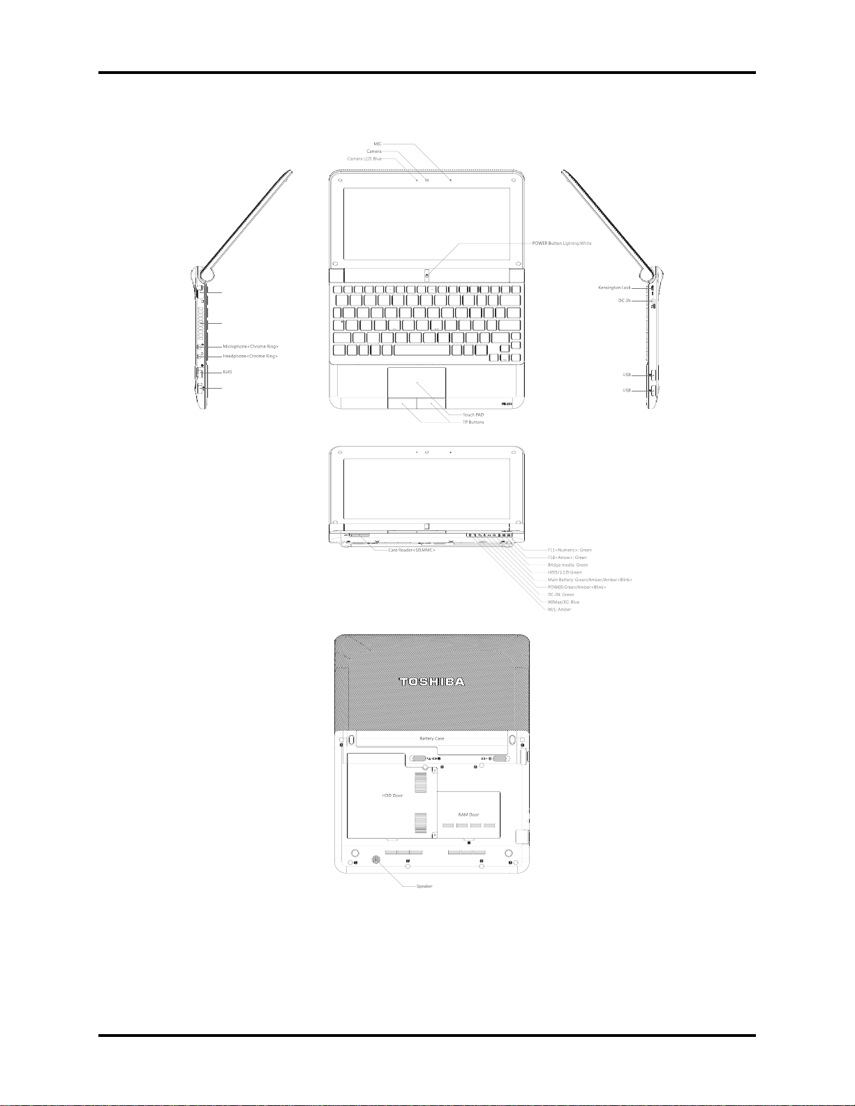
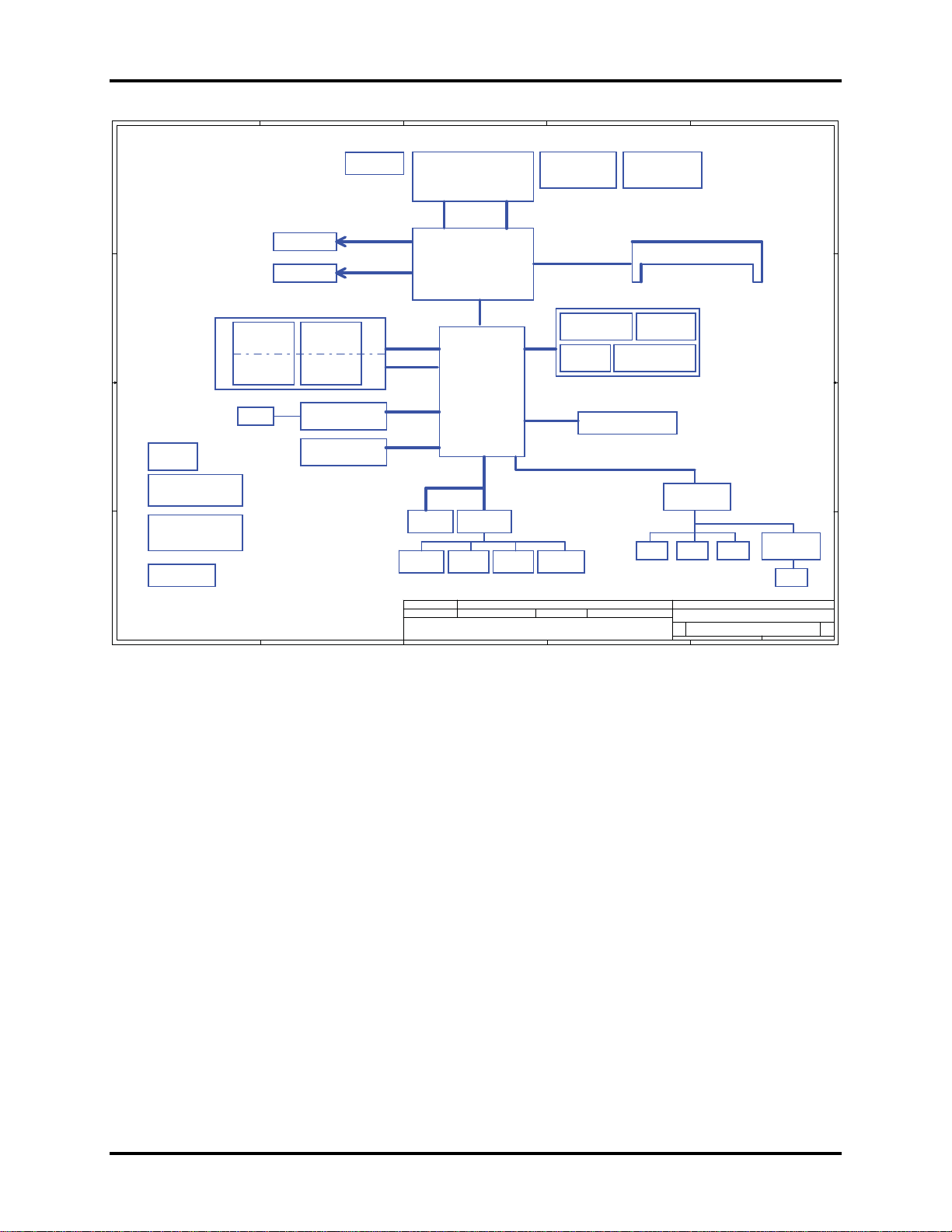
Figure 1-1A shows the computer and its system unit configuration.
External monitor port
Thermal vent holes
USB ( USB Sleep and Charge function
is supported by this port only. )
Figure 1-1A ID Parts Description Placement Part A
NB250/NB255 Maintenance Manual 1-4
Page 20
1.1 Features 1 Hardware Overview
A
B
C
D
E
Compal Confidential
Thermal Sensor
)36..0(#D_H)13..3(#A_H
Memory BUS(DDRII)
USB
5V 480MHz
SATA port 0
5V 1.5GHz(150MB/s)
HD Audio
GSENSOR
page 28
Compal Secret Data
Deciphered Date
EMC1402
page 4
1.8V DDRII 400/533
USB Conn X3
USB port 0,2,7
BT conn
USB port 6
page 21
SATA HDD&SSD
3.3V 24.576MHz/48Mhz
page 27
Clock Generator
SLG8SP556VTR
200pin DDRII-SO-DIMM
Int. Camera
page 20
USB port 1
Touch Screen conn
BTO USB port 4 ,5
page 21
Int.
MIC CONN
page 23 page 23 page 23
D
page 12
page 11
page 21
page 20
HDA Codec
ALC272-GR
page 22
AMP.
E
TPA6017
page 23
SPK CONN
page 23
242Monday, March 23, 2009
HP CONN
MIC CONN
Compal Electronics, Inc.
Title
Block Diagrams
Size Document Number Re v
KAVAA LA-5121P M/B
Date: Sheet of
1.A
page 14
page 13
PCIeMini Card
3G
USB port 5
page 19
PCIeMini Card
GPS
USB port 5
page 19
RTL8103EL 10/100M
PCIe port 3
Card Reader
RTS5159 2IN1
USB port 3
B
Fan Control
page 28
LVDS
ONE CHANNEL
page 24
page 25
Intel Diamondville SC
FCBGA8-437 Pins
(22x22mm)
FSB
400/533MHz
page 4,5
Intel Calistoga GSE
FCBGA998
(27x27mm)
page 6,7,8,9,10
DMI x 2
USB
5V 480MHz
PCIe 1x [2,4]
1.5V 2.5GHz(250MB/s)
1.5V 2.5GHz(250MB/s)
5V 480MHz
Intel ICH7M
page 28
page 29
Issued Date
BGA-652
(31x31mm)
page 15,16,17,18
3.3V 33 MHz
LPC BUS
ENE KB926 D3
page 26
SPI ROM
Int.KBD
page 28
2009/03/20 2010/03/20
C
PCIe 1x
USB
Debug Port
Touch Pad
Security Classification
THIS SHEET OF ENGINEERING DRAWING IS THE PROPRIETARY PROPERTY OF COMPAL ELECTRONICS, INC. AND CONTAINS CONFIDENTIAL
AND TRADE SECRET INFORMATION. THIS SHEET MAY NOT BE TRANSFERED FROM THE CUSTODY OF THE COMPETE NT DIVISI ON OF R& D
DEPARTMENT EXCEPT AS AUTHORIZED BY COMPAL ELECTRONICS, INC. NEITHER THIS SHEET NOR THE INFORMATION IT CONTAINS
MAY BE USED BY OR DISCLOSED TO ANY THIRD PARTY WITHOUT PRIOR WRITTEN CONSENT OF COMPAL ELECTRONICS, IN C.
Model Name : KAVAA
File Name : LA-5121P
1 1
CRT Conn.
LED Conn.
2 2
3 3
RTC CKT.
page 16
PCIeMini Card
WiMax
USB port 4
page 19
PCIeMini Card
WLAN
PCIe port 2
page 19
RJ45
page 24
DC/DC Interface CKT.
page 30
Power Circuit DC/DC
page 31~37
Power/B
4 4
page 29
A
NB250/NB255 Maintenance Manual 1-5
Page 21

1 Hardware Overview 1.1 Features
The system unit of the computer consists of the following components:
Processor
The computer is equipped with the following Intel® processor:
Intel® PineviewTM Processor.
Memory (BTO)
The computer has one SODIMM slot which comes standard with 1GB/2GB, accepting BTO
for your memory requirements. It can incorporate up to 1 GB (XP) or 2 GB (Vista/Linux) of
main memory. It supports DDR3 at 667MHz.
BIOS ROM (EEPROM)
The system BIOS and Keyboard BIOS share one single 1024KB flash ROM. The flash
utility can be used to program both system and keyboard BIOS at the same time.
System Controllers
ACPI2.0b and Windows Logo Program 3.0 compliant
Support SMBus specification V2.0
Hot keys for system control
Audio volume output control
Battery scope report and control
Power switch control
Internal Keyboard country selection
Graphics Controller
Intel® NM10 Express Chipset for integrated graphics display.
TVAP and Smart External Monitor Support
NB250/NB255 Maintenance Manual 1-6
Page 22

1.1 Features 1 Hardware Overview
Audio Controller
Realtek Azalia ALC272
One Audio-in port: Mic-in/Line-in
One Audio-out port: Headphone-out/Line-out
Internal Microphone (MIC with echo cancellation)
Volume control: Digital control, Hot keys (Fn+3, Fn+4)
Microsoft inbox audio driver support
Wireless LAN Controller
Atheros 802.11 bg (HB95 1x1)
WPS supported
NB250/NB255 Maintenance Manual 1-7
Page 23
1 Hardware Overview 1.2 2.5-inch HDD
1.2 2.5-inch HDD
The computer contains a low-profile and light-weight, high-performance HDD. The HDD
interface conforms to Serial ATA. Storage capacities supported are 120 and 160 GB.
The HDD is shown in Figure 1-2 and some of its specifications are listed in Table 1-1.
Figure 1-2 S-ATA HDD
Table 1-1 HDD Specifications
Item
Capacity (GB) 160 GB 250G
Rotational Speed (RPM) 5400 RPM 5400
Height 9.5mm, 2.5” 9.5mm, 2.5”
User Data Sectors 312,581,808 488,397,168
Bytes / Sector
512 512
Specifications
NB250/NB255 Maintenance Manual 1-8
Page 24

1.3 Power Supply 1 Hardware Overview
1.3 Power Supply
The power supply unit provides constant voltage (19V) for the system board and performs the
following functions:
1. Power input monitor
Checks whether the AC adapter (DC power supply) is connected to the computer.
Checks whether the battery pack is connected to the computer.
Monitors the DC power supply input voltage (AC Adapter output voltage).
2. Power supply's internal control
Turns on and off the battery pack charging power supply.
Issues a charging current instruction to the PWM control IC of the battery pack charging
power supply.
Controls the supply of DC power supply input (AC Adapter output) to the power supply
unit.
Controls the supply of power to the system block (load/logic circuit side).
Controls forced shutdown if the power supply malfunctions.
3. Logic circuit control
Instructs the gate array to enable/disable tuning the power on.
Controls power-on/off operation.
4. Status display
Turns on the Power LED (in Green).
Battery indicator (in Green or Amber).
DC-IN indicator (in Green)
5. External interface
Performs communication through the I2C bus (via the internal EC/KBC).
Transfers the power supply operation mode.
NB250/NB255 Maintenance Manual 1-9
Page 25

1 Hardware Overview 1.3 Power Supply
6. Output monitor
Monitors the voltage output to the system block (load/logic circuit side).
Monitors the voltage, over voltage, input/output current of the battery pack.
Monitors the internal temperature of the battery pack.
Monitors the supply voltage from the AC adapter.
NB250/NB255 Maintenance Manual 1-10
Page 26
1.4 Batteries 1 Hardware Overview
1.4 Batteries
The computer has the following two types of batteries:
Main Battery Pack
Real Time Clock (RTC) Battery
1.4.1 Main Battery
The main battery pack serves as the computer's main power source when the AC adapter is not
attached. The main battery maintains the state of the computer when the AC adapter is detached.
1.4.2 Battery Charging Control
Battery charging is controlled by EC KB926. When the AC adapter and battery pack are attached
to the computer, the EC KB926 controls the charge on/off state and detects a full charge.
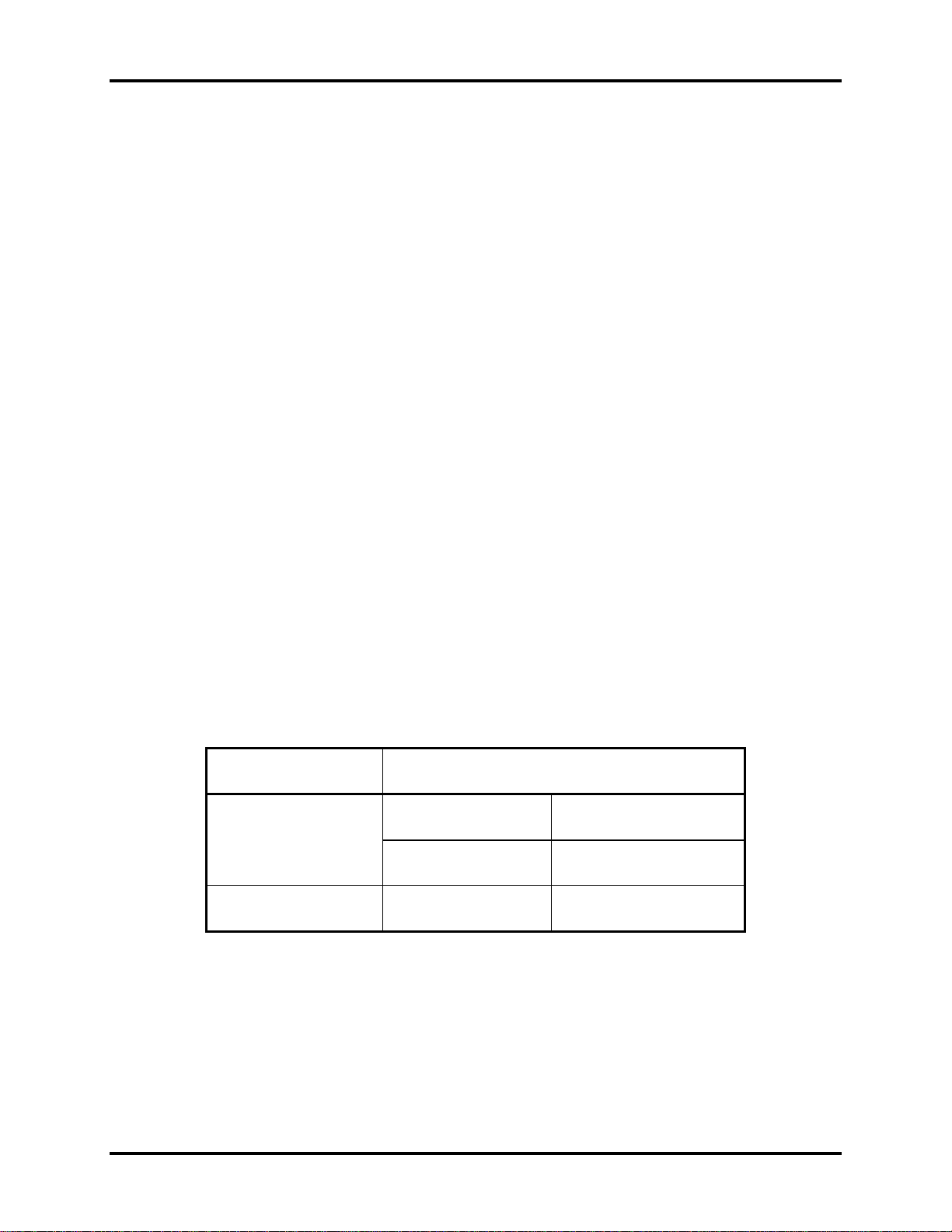
Battery Charge
When the AC adapter is attached, the battery is charged by off-state charge when the system
is powered off or by on-state charge when it is powered on.
Table 1-2 Quick/Normal Charging Time
State Charge Time
3 Cell About 4 hours
Off-State Charge
6 Cell About 6 hours
On-State Charge 3/6 Cell About 12 hours
NB250/NB255 Maintenance Manual 1-11
Page 27

1 Hardware Overview 1.4 Batteries
NOTE: The time required for normal charge depends on the power consumption by the
system. Using a fluorescent lamp and frequently accessing the disk consumes more power and
lengthens the charge time.
Any of the following can stops battery charge:
1. The battery becomes fully charged.
2. The AC adapter or battery pack is removed.
3. The battery or AC adapter voltage is abnormal.
Detection of full charge
A full charge is detected only when the battery is being charged by quick or normal charge.
A full charge is detected when either of the following conditions is met:
1. The current in the battery charging circuit drops below the predetermined value.
2. The charging time exceeds the fixed limit.
1.4.3 RTC Battery
The RTC battery provides power to keep the current date, time and other system information in
memory while the computer is turned off.
NB250/NB255 Maintenance Manual 1-12
Page 28

Chapter 2
Troubleshooting Procedures
2
Page 29

Page 30

2 Troubleshooting Procedures
Chapter 2 Contents
2.1 Troubleshooting Introduction......................................................................................3
2.2 Troubleshooting Flowchart..........................................................................................3
2.3 Power Supply Troubleshooting ...................................................................................9
2.4 Display Troubleshooting ...........................................................................................14
2.5 Keyboard Troubleshooting........................................................................................17
2.5 External USB Devices Troubleshooting..........................................................................19
2.6 TouchPad Troubleshooting.............................................................................................21
2.7 Speaker Troubleshooting................................................................................................23
2.6 Wireless LAN Troubleshooting.................................................................................25
2.7 Camera Troubleshooting ...........................................................................................27
2.8 Bluetooth Troubleshooting........................................................................................29
2.9 2in1 card Troubleshooting.........................................................................................31
2.10 HDD/SSD Troubleshooting.......................................................................................33
2.13 CRT Troubleshooting ....................................................................................................36
2.14 LAN Troubleshooting....................................................................................................38
2. 17 3G Troubleshooting............................................................................................44
NB250/NB255 Series Maintenance Manual
1
Page 31

2 Troubleshooting Procedures
Figures
Figure 2-1 Troubleshooting flowchart (1/2) .......................................................................5
Figure 2-1 Troubleshooting flowchart (2/2) ...................................................................... 6
Figure 2-2 Power Supply Troubleshooting Process............................................................9
Figure 2-3 Display troubleshooting process .....................................................................14
Figure 2-4 Keyboard troubleshooting process..................................................................17
Figure 2-5 External USB device troubleshooting process................................................20
Figure 2-6 TouchPad troubleshooting process..................................................................25
Figure 2-7 Speaker troubleshooting process.....................................................................27
Figure 2-8 Wireless LAN troubleshooting process...........................................................29
Figure 2-9 Camera troubleshooting process .....................................................................31
Figure 2-10 Bluetooth troubleshooting process…..……………………………….……….33
Figure 2-11 2 in 1 card troubleshooting process……………………………..…….………35
Figure 2-12 HDD/SSD troubleshooting process……………………….……..…………..37
Figure 2-13 CRT troubleshooting process ……………………………………………….39
Figure 2-14 LAN troubleshooting process ……………………………………………….41
Figure 2-15 MIC troubleshooting process ……………………………………………….....43
Figure 2-16 3D sensor troubleshooting process ……………………………………………45
Figure 2-17 3G troubleshooting process …………………………………………………...47
Tables
Table 2-1 Battery LE
Table 2-2 DC-IN LED
D .......................................................................................................10
........................................................................................................11
NB250/NB255 Series Maintenance Manual
2
Page 32

2 Troubleshooting Procedures
2.1 Troubleshooting Introduction
Chapter 2 describes how to determine if a Field Replaceable Unit (FRU) in the computer is
causing the computer to malfunction. The FRUs covered are:
1. Display 7. Wireless LAN 13. External ODD
2. HDD/SSD 8. Camera 14. Bridge media
3. Keyboard 9. Bluetooth(10BL no support) 15. 3D sensor(10BL no support)
4. USB ports 10. Headphone 16. Sleep charge(10BL no support)
5. Touchpad 11.MIC
6. Speaker 12. 3G module(10BL no support)
The Diagnostics Disk operations are described in Chapter 3. Detailed replacement
procedures are given in Chapter 4.
The following tools are necessary for implementing the troubleshooting procedures:
1. Phillips screwdriver (2 mm)
2. 6mm nut driver (for the helix screw nuts on the rear ports for RAM door)
3. 2DD or 2HD formatted work disk for floppy disk drive testing
4. Torx screw driver with type T6 bit for HDD door
5. USB memory disk
6. Multimeter
7. External monitor\ODD
8. USB compatible keyboard
9. Multimedia sound system with line-in and line-out ports
10. Headphones
11. USB test module and USB cable
12. MIC line
2.2 Troubleshooting Flowchart
If you know the location of the malfunction, turn directly to the appropriate section of this
chapter. If the problem is unspecified, use the flowchart in Figure 2-1 as a guide for
determining which troubleshooting procedures to execute. Before performing any
troubleshooting procedures, verify the following:
Ask the user if a password is registered, if it is, ask him or her to enter the password.
Verify with the customer that Toshiba Windows XP/Vista/Linux is installed on the hard
disk. Operating systems that were not preinstalled by Toshiba can cause the computer to
malfunction.
NB250/NB255 Series Maintenance Manual
3
Page 33

2 Troubleshooting Procedures
Make sure all optional equipment is removed from the computer.
NB250/NB255 Series Maintenance Manual
4
Page 34

2 Troubleshooting Procedures
C onnect the A C adapter to the D C -
IN sock et
Is the DC-IN LED on?
Is the B attery L E D on?
START
Yes
Yes
No
No
Perform the Power Supply
Troubleshooting procedures
in section 2.3
P erfo rm the P o wer S up p ly
Troubleshooting procedures
in s ec tio n 2.3
T urn th e P o w e r switch o n
Yes
Is the Power On LED on?
Yes
Is the "T oshiba" logo m essage
display?
Yes
If the "passw ord" m essage
displays, type the passw ord, then
press E nter.
Is T oshiba W indows or Linux
being loaded?
Yes
No
No
No
P erfo rm the P o wer S up p ly
Troubleshooting procedures
in s ec tio n 2.3
P erfo rm the P o wer S up p ly
Troubleshooting procedures
in s ec tio n 2.3
Perform diagnostics
program . R un CM165.E X E
and select the H A R D D ISK
item .
A
Figure 2-1 Troubleshooting flowchart (1/2)
NB250/NB255 Series Maintenance Manual
5
Page 35

2 Troubleshooting Procedures
A
Does typed characters appear correctly?
Yes
Insert USB memory disk. Then run the
diagnostics test program
Yes
No
Perform the Keyboard
Troubleshooting procedures
in section 2.6
Is the diagnostics test loaded?
Yes
Allow each test to perform
automatically
Is an error detected by any of the
diagnostics tests?
No
System is normal
No
Yes
Perform the FDD
Troubleshooting procedures
in section 2.5
After confirming which
diagnostics test has detected
an error, perform the
appropriate procedure as
outlined below.
End
Figure 2-1 Troubleshooting flowchart (2/2)
NB250/NB255 Series Maintenance Manual
6
Page 36

2 Troubleshooting Procedures
If the diagnostics program cannot detect an error, the problem may be intermittent. The test
program should be executed several times to isolate the problem. When a problem has been
located, perform the appropriate troubleshooting procedures as follows:
1. If an error is detected by the battery test, perform th e Power Supply Troubleshooting
procedures in Section 2.3
2. If an error is detected by the display test, perform the Display Troubleshooting
procedures in Section 2.4
3. If an error is detected by the keyboard test, perform the Keyboard Troubleshooting
procedures in Section 2.5
4. If an error is detected by the TouchPad test, perform the TouchPad Troubleshooting
procedures in Section 2.7
5. If an error is detected by the audio test, perform the Speaker Troubleshooting
procedures in Section 2.8 and the Optical Drive Troubleshooting Procedures in
Section 2.9
NB250/NB255 Series Maintenance Manual
7
Page 37

2 Troubleshooting Procedures
Other problems that are not covered by the diagnostics program may be discovered by a
user.
1. If an error is detected when using an external USB device, perform the External USB
Devices Troubleshooting procedures in Section 2.6
2. If an error is detected when using the speakers, perform the Speaker Troubleshooting
procedures in Section 2.8
3. If an error is detected when using the Wireless LAN, perform the Wireless LAN
Troubleshooting procedures in Section 2.10
4. If an error is detected when using the Bluetooth, perform the Bluetooth
Troubleshooting procedures in Section 2.12
5. If an error is detected when using the MIC, perform the MIC troubleshooting
procedures in Section 2.16
NB250/NB255 Series Maintenance Manual
8
Page 38

2 Troubleshooting Procedures
2.3 Power Supply Troubleshooting
START
Check Power Supp ly Status
(Procedure 1)
Are the DC-IN and
Ba tte ry L ED s lit?
Yes
Check power supply
connections
(Procedure 3)
Can you turn the
computer on?
No
Are th e in te rn a l p o w er
connections secure?
No
Yes
No
Replace adaptor / battery
(Procedure 2)
Run diagnostic program
(Procedure 4)
Pe rfo rm in ter na l c o nn e cti on
check
(Procedure 5)
Yes
Replace system board
END
Figure 2-2 Power Supply Troubleshooting Process
The power supply controls many functions and components. To determine if the power
supply is functioning properly, start with Procedure 1 and continue with the other Procedures
NB250/NB255 Series Maintenance Manual
9
Page 39

2 Troubleshooting Procedures
as instructed. The flowchart in Figure 2-2 gives a summary of the process. The procedures
described in this section are:
Procedure 1: Power status check
Procedure 2: Adaptor / battery replacement
Procedure 3: Power supply connection check
Procedure 4: Diagnostic check
Procedure 5: Internal connection check
Procedure 1 Power Status Check
The following LEDS indicate the power supply status:
Battery LED
DC-IN LED
The power supply controller displays the power supply status through the Battery and the DCIN LEDS as listed in the tables below.
Table 2-1 Battery LED
NB250/NB255 Series Maintenance Manual
10
Page 40

2 Troubleshooting Procedures
Table 2-2 DC-IN LED
DC-IN LED Power supply status
Solid on AC power exists (LED is Green).
Off No AC power exists.
To check the power supply status, install a battery pack and connect an AC adaptor to the
DC-IN port on the computer and to a power supply.
If the DC-IN LED or Battery LED is not lit, go to Procedure 2.
Procedure 2 Adaptor / battery replacement
A faulty adaptor may not supply power or may not charge the battery. Perform Check 1.
Check 1 Connect a new AC adaptor. If the problem is not resolved, go to Check 2.
Check 2 Insert a new battery. If the problem is still not resolved, go to Procedure 3.
NB250/NB255 Series Maintenance Manual
11
Page 41

2 Troubleshooting Procedures
Procedure 3 Power supply connection check
The power supply wiring diagram is shown below:
A C ad aptor cord
AC power cord
AC
adaptor
Any of the connectors may be disconnected. Perform Check 1.
Check 1 Disconnect the AC power cord from wall outlet. Check the power cable for
breaks. If the power cord is damaged, connect a new AC power cord. If there is
no damage, go to Check 2.
Check 2 Make sure the AC adaptor cord and AC power cord are firmly plugged into the
DC-IN socket, AC adaptor inlet and wall outlet. If these cables are connected
correctly, go to Check 3.
Check 3 Make sure that the DC-IN input port socket is firmly secured to the system board
of the computer.
If the DC-IN input socket is loose, go to Procedure 5.
If it is not loose, go to Check 4.
System
board
B a tter y
Check 4 Use a multi-meter to make sure that the AC adaptor output voltage is close to 19
V. If the output is several percent lower than 19 V, go to Check 5. If the output
is close to 19 V, go to Check 6.
Check 5 Connect a new AC adaptor or AC power cord.
If the DC-IN LED does not light, go to Procedure 4.
If the battery LED does not light, go to Check 6.
Check 6 Make sure the battery pack is installed in the computer correctly. If the battery is
properly installed and the battery LED still does not light, go to Procedure 4.
NB250/NB255 Series Maintenance Manual
12
Page 42

2 Troubleshooting Procedures
Procedure 4 Diagnostic check
The power supply may not charge the battery pack. Perform the following procedures:
1. Reinstall the battery pack.
2. Attach the AC adaptor and turn on the power. If you cannot turn on the power, go to
Procedure 5.
3. Run the Diagnostic test following the procedures described in Chapter 3, Tests and
Diagnostics. If no problem is detected, the battery is functioning normally.
Procedure 5 Replacement check
The system board may be disconnected or damaged. Disassemble the computer following the
steps described in Chapter 4, Replacement Procedures. Check the connection between the AC
adaptor and the system board. After checking the connection, perform Check 1:
Check 1 Use a multi-meter to make sure that the fuses on the system board are not blown.
If a fuse is not blown, go to Check 2. If a fuse is blown, go to Check 3.
Check 2 Make sure that the battery cable is firmly connected to the system board. If it is
connected firmly, go to Check 3.
Check 3 The system board may be damaged. Replace it with a new one following the
instructions in Chapter 4.
NB250/NB255 Series Maintenance Manual
13
Page 43

2 Troubleshooting Procedures
2.4 Display Troubleshooting
Perform external display check
display function ok?
STAR T
(Procedure 1)
D oes the external
No
Yes
Perform diagnostic check
(Procedure 2)
Was a display
problem detected?
Yes
Perform connector and
replacement check
(Procedure 3)
Rep lace system bo ard
END
No
Display is not
faulty. Continue
troubleshooting-
refer to F igu re 2 .1
Figure 2-3 Display troubleshooting process
NB250/NB255 Series Maintenance Manual
14
Page 44

2 Troubleshooting Procedures
This section describes how to determine if the computer’s display is functioning properly.
The process is outlined in Figure 2-3. Start with Procedure 1 and continue with the other
procedures as instructed.
Procedure 1: External display check
Procedure 2: Diagnostic check
Procedure 3: Connector and replacement check
Procedure 1 External display check
Connect an external display to the computer’s external monitor port, and then boot the
computer. The computer automatically detects the external display.
If the external display works correctly, the internal LCD may be damaged. Go to Procedure 3.
If the external monitor appears to have the same problem as the internal monitor, the system
board may be damaged. Go to Procedure 2.
Procedure 2 Diagnostic check
The Display Test program is stored on the computer’s Diagnostics disk. This program checks
the display controller on the system board. Insert the Diagnostics disk in the computer’s
floppy disk drive, turn on the computer and run the test. Refer to Chapter 3, Tests and
Diagnostics for details.
If an error is detected, go to Procedure 3. If an error is not detected, the display is functioning
properly.
NB250/NB255 Series Maintenance Manual
15
Page 45

2 Troubleshooting Procedures
Procedure 3 Connector and replacement check
The LCD module and system board are connected to the display circuits. Any of these
components may be damaged. Refer to Chapter 4, Replacement Procedures, for instructions
on how to disassemble the computer and then perform the following checks:
Check 1 Make sure the DDR module is seated properly. Test display again. If the problem
still exits, replace the DDR RAM module. If the problem still exists, perform
Check 2.
Check 2 Replace the LCD module with a new one and test display again. If the problem
still exists, perform Check 4.
Check 3 Replace the LCD cable with a new one and test display again. If the problem still
exists, perform Check 5.
Check 4 The system board may be damaged. Replace it with a new one.
NB250/NB255 Series Maintenance Manual
16
Page 46

2 Troubleshooting Procedures
2.5 Keyboard Troubleshooting
STAR T
No
Perform external keyboard check
Perform diagnostic check
(Procedure 1)
D oes the external
keyboard function ok?
Yes
(Procedure 2)
W as a keyboard
problem detected?
Yes
No
Keyboard is not
faulty. Continue
troubleshooting-refer
to Figure 2.1
Pe rform co nn ec tor an d
replacemen t check
(Procedure 3)
Rep lace system bo ard
END
Figure 2-4 Keyboard troubleshooting process
NB250/NB255 Series Maintenance Manual
17
Page 47

2 Troubleshooting Procedures
To determine if the computer’s keyboard is functioning properly, perform the following
procedures. Figure 2-5 outlines the process. Start with Procedure 1 and continue with the
other procedures as instructed.
Procedure 1: External keyboard check
Procedure 2: Diagnostic check
Procedure 3: Connector and replacement check
Procedure 1 External keyboard check
Connect a USB keyboard to one of the computer’s USB ports, and then boot the computer.
The computer automatically detects the external keyboard.
If the external keyboard works correctly, the internal keyboard or its connections may be
faulty. Go to Procedure 2.
If the external keyboard appears to have the same problem as the internal keyboard, the
system board may be having some problem. Replace it with a new one and following the
instructions in Chapter 4.
Procedure 2 Diagnostic check
Run the test and Diagnostics Program, which will automatically execute the Keyboard Test.
Refer to Chapter 3, Tests and Diagnostics for more information on how to run the program.
If an error is located, go to Procedure 3. If an error does not occur, the keyboard is
functioning ok.
Procedure 3 Connector and replacement check
The keyboard and/or system board may be disconnected or damaged. Disassemble the
computer following the steps described in Chapter 4, Replacement Procedures and perform
the following checks.
Check 1 Make sure the keyboard cable is firmly connected to the system board.
If the connection is loose, reconnect firmly and repeat Procedure 2. If there is still
an error, go to Check 2.
Check 2 The keyboard may be damaged. Replace it with a new one following the
instructions in Chapter 4.
If the problem still exists, perform Check 3.
Check 3 The system board may be damaged. Replace it with a new one following the
instructions in Chapter 4.
NB250/NB255 Series Maintenance Manual
18
Page 48

2 Troubleshooting Procedures
2.5 External USB Devices Troubleshooting
STAR T
Pe rform exte rna l de vice an d
connection check
(Pro ce d ure 1 )
Check USB
port
connection
D o e s th e d ev ic e fu n ctio n
Yes
wh en conn ected to a
differe nt US B po rt?
D oes an alternative US B
device function correctly?
Replace system board
(Pro ce d ure 2 )
No
No
END
O r ig in al U S B
Yes
device is faulty
Figure 2-5 External USB device troubleshooting process
NB250/NB255 Series Maintenance Manual
19
Page 49

2 Troubleshooting Procedures
To determine if the computer’s external USB devices are functioning properly, perform the
following procedures. Figure 2-6 outlines the process. Start with Procedure 1 and continue as
instructed.
Procedure 1: External device and connection check
Procedure 2: Replace system board
Procedure 1 External device and connection check
The USB device may be damaged or the connection may be faulty. Perform Check 1.
Check 1 Make sure USB device cable is firmly plugged into one of the USB sockets. If the
cable is connected correctly, go to Check 2.
Check 2 Plug the USB device into another USB socket (there are three in all). If the USB
device still does not work, go to Check 4.
If the device functions correctly when connected to another USB port, go to
Check 3.
Check 3 Make sure that the USB socket is firmly secured to the system board of the
computer. If the malfunction remains, the system board or USB small board may
be damaged. Go to Procedure 2.
Check 4 Connect an alternative USB device to one of the computer’s USB ports, and then
boot the computer. The computer automatically detects the external device.
If the alternative USB device works correctly, the original device may be
damaged and should be replaced.
If the alternative USB device appears to have the same problem as the original
device, the system board or USB small board may be damaged. Go to Procedure
2.
Procedure 2 Replace system board
If the error persists, the system board or USB small board may be damaged. Replace it with a
new one following the instructions in Chapter 4.
NB250/NB255 Series Maintenance Manual
20
Page 50

2 Troubleshooting Procedures
2.6 TouchPad Troubleshooting
START
TouchPad connection
check (Procedure 1)
TouchPad replacement
check (Procedure 2)
Replace system board
END
Figure 2-6 Touchpad troubleshooting process
NB200 Series Maintenance Manual
21
Page 51

2 Troubleshooting Procedures
To determine if the computer’s built-in TouchPad is functioning properly, perform the
following procedures. Figure 2-9 outlines the process. Start with Procedure 1 and continue as
instructed.
Procedure 1: TouchPad connection check
Procedure 2: TouchPad replacement check
Procedure 1 TouchPad connection check
The TouchPad is connected via the TouchPad FPC to the system board. Make sure the
TouchPad FPC cable is firmly connected to the TouchPad and system board. Refer to Chapter
4, Replacement Procedures, for instructions on how to disassemble the computer and then
perform the following checks.
If any of the connections are loose, reconnect firmly. If any of the connections is damaged, or
there is still an error, go to Procedure 2.
Procedure 2 TouchPad replacement check
The TouchPad unit or FPC may be defective or damaged. Replace each with a new one
following the steps in Chapter 4. If the FDD is still not functioning properly, replace the
system board with a new one following the steps in Chapter 4.
NB200 Series Maintenance Manual
22
Page 52

232 Troubleshooting Procedures
2.7 Speaker Troubleshooting
Perform audio source test
P erform earp ho ne test
START
(P roc ed ure 1)
D o all sources have
same problem?
Yes
(P roc ed ure 2)
No
Speakers are no t
faulty. C ontinue
troubleshooting -
see Figure 2-1
Do earphones
function correctly?
Yes
Perform connection check
No
(P roc ed ure 3)
Perform replacement
check
(P roc ed ure 4)
R eplac e system b oa rd
END
Figure 2-7 Speaker troubleshooting process
NB200 Series Maintenance Manual
23
Page 53

242 Troubleshooting Procedures
To determine if the computer’s built-in speakers are functioning properly, perform the
following procedures. Figure 2-10 outlines the process. First adjust the speaker volume to an
appropriate level. Start with Procedure 1 and continue as instructed.
Procedure 1: Audio source test
Procedure 2: Earphone test
Procedure 3: Connection check
Procedure 4: Replacement check
Procedure 1 Audio source test
Try different audio sources (e.g. an audio CD and digital music file) to determine whether the
fault is in the speaker system or not. If not all sources have sound problem, the problem is in
the monaural devices. If all have the same problem, continue with Procedure 2.
Procedure 2 Earphone test
Connect a set if earphones or external speakers. If these function correctly, go to Procedure 3.
If they do not function correctly, the system board may be defective or damaged. Replace it
with a new one.
Procedure 3 Connection check
Disassemble the computer following the steps described in Chapter 4, Replacement
Procedures and make sure the speaker cable is firmly connected to the audio board. If the
speakers are still not functioning properly, go to Procedure 4.
Procedure 4 Replacement check
If the monaural speakers don't sound properly, the monaural speakers may be defective or
damaged. Replace them with new ones. If the monaural speakers still do not work properly,
try replacing in turn the audio board and system board.
NB200 Series Maintenance Manual
24
Page 54

252 Troubleshooting Procedures
2.6 Wireless LAN Troubleshooting
Perform diagnostic test
Was a w ireless LAN problem d elected?
START
(Procedure 1)
Yes
No
Wireless LAN system
is not fau lty. C on tin u e
troubleshooting - refer
to Figure 2 .1
Perform connector and replacem ent check
(Procedure 2)
Replace wireless LAN an tenna/unit
Replace system board
END
Figure 2-8 Wireless LAN troubleshooting process
The wireless LAN antenna wire, wireless LAN unit or system board may each be the source
of a wireless LAN fault. Any of these components may be damaged. To determine if the
NB200 Series Maintenance Manual
25
Page 55

262 Troubleshooting Procedures
computer’s wireless LAN system is functioning properly, perform the following procedures.
Figure 2-15 outlines the process. Start with Procedure 1 and continue with the other
procedures as instructed.
Procedure 1: Diagnostic test
Procedure 2: Connector and replacement check
Procedure 1 Diagnostic test
Run the Diagnostic Program, which will automatically execute the wireless LAN test. Test
and Diagnostic for more information on the program.
If an error is located, go to Procedure 2. If an error is not located, the wireless LAN system is
functioning properly.
Procedure 2 Connector and replacement check
The wireless LAN antenna, wireless LAN unit or system board may be disconnected or
damaged. Disassemble the computer following the steps described in Chapter 4, Replacement
Procedures, and perform the following checks.
Check 1 Make sure that the wireless LAN antenna is firmly connected to the Wireless
LAN module (refer to Chapter 4 for instructions) and that the wireless LAN
module is securely slotted into the system board. If the problem persists, go to
Check 2.
Check 2 Check that the wireless communication function is enable by BIOS setup and
FN+F8 , and then make sure that the wireless communication LED on the front
panel is light. If the LED is light but the wireless LAN function is still faulty, the
antenna may be damaged. Replace with a new antenna following the steps in
Chapter 4, Replacement Procedures. If the problem persists, or if the wireless
LAN LED is not light when the wireless communication function is enabled by
BIOS setup and FN+F8, go to Check 3.
Check 3 The wireless LAN unit may be damaged. Replace it with a new one following the
instructions in Chapter 4. If the problem still exists, perform Check 4.
Check 4 The system board may be damaged. Replace it with a new one following the
instructions in Chapter 4.
NB200 Series Maintenance Manual
26
Page 56

272 Troubleshooting Procedures
2.7 Camera Troubleshooting
Figure 2-9 Camera troubleshooting process
NB200 Series Maintenance Manual
27
Page 57

282 Troubleshooting Procedures
The Camera board or system board may be the reason of a Camera fault. Either of these two
components may be damaged. To determine if the computer’s Camera is functioning
properly, perform the following procedures. Figure 2-14 outlines the process. Start with
Procedure 1 and continue with the other procedures as instructed.
Procedure 1: Diagnostic test
Procedure 2: Connector and replacement check
Procedure 1 Diagnostic test
Run the functioning Program in windows, which will display the Camera test result.
If tests and diagnostics result abnormal go to Procedure 2. If an error is not located, the
Camera system is functioning properly.
Procedure 2 Connector and replacement check
The Camera board or system board may be disconnected or damaged. Disassemble the
computer following the steps described in Chapter 4, Replacement Procedures, and perform
the following checks.
Check 1 Make sure that the Camera board cable is securely slotted into the system board.
If the problem persists, go to Check 2.
Check 2 The Camera board may be damaged. Replace it with a new one following the
instructions in Chapter 4. If the problem still exists, perform Check 3.
Check 3 The system board may be damaged. Replace it with a new one following the
instructions in Chapter 4.
NB200 Series Maintenance Manual
28
Page 58

292 Troubleshooting Procedures
2.8 Bluetooth Troubleshooting
Figure 2-10 Bluetooth troubleshooting process
NB200 Series Maintenance Manual
29
Page 59

302 Troubleshooting Procedures
The Bluetooth antenna wire, Bluetooth module or system board may be the reason of a
Bluetooth fault. Any of these components may be damaged. To determine if the computer’s
Bluetooth is functioning properly, perform the following procedures. Figure 2-16 outlines the
process. Start with Procedure 1 and continue with the other procedures as instructed.
Procedure 1: Diagnostic test
Procedure 2: Connector and replacement check
Procedure 1 Diagnostic test
Run the Diagnostic Program, which will automatically execute the Bluetooth test. Refer to
Chapter 3, Tests and Diagnostics for more information on the program.
If an error is located, go to Procedure 2. If an error is not located, the Bluetooth system is
functioning properly.
Procedure 2 Connector and replacement check
The Bluetooth, antenna module or system board may be disconnected or damaged.
Disassemble the computer following the steps described in Chapter 4, Replacement
Procedures, and perform the following checks.
Check 1 Make sure the Bluetooth cable is securely slotted into the system board. If the
problem persists, go to Check 2.
Check 2 Check the wireless communication function is enabled by BIOS setup and
FN+F8, then make sure that the communication LED on the left panel is lit. If the
problem persists, or if the Bluetooth communication LED is not lit when the
wireless communication function is enabled by BIOS setup and FN+F8 to “On”,
go to Check 3.
Check 3 The Bluetooth module may be damaged. Replace it with a new one following the
instructions in Chapter 4. If the problem still exists, perform Check 4.
NB200 Series Maintenance Manual
30
Page 60

312 Troubleshooting Procedures
Check 4 The system board may be damaged. Replace it with a new one following the
instructions in Chapter 4.
2.9 2in1 card Troubleshooting
START
Perform 2 in 1 CARD test
(Procedure 1)
Do errors occur during 2
IN 1 CARD test?
Yes
Perform 2 IN 1 card socket
replacement check
(Procedure 2)
2 IN 1 unit is not
No
faulty.
Replace system board
END
Figure 2-11 2in 1 card troubleshooting process
NB200 Series Maintenance Manual
31
Page 61

322 Troubleshooting Procedures
This section describes how to determine if the 2 IN 1 Card is functioning properly. The
process is summarized in Figure 2-16. Perform the steps below starting with Procedure 1 and
continuing with the other procedures as required.
Procedure 1: 2 in 1 card test
Procedure 2: 2 in 1 card socket check
Procedure 1 2 in 1card test
The 2 in 1 Card test card contains a 2 in 1 card test program. Ensure the card in fully inserted
into the socket before running the program.
If an error occurs during the 2in 1 card test, perform Procedure 2. If no error occurs, it is
likely that the original 2 in 1 card was faulty.
Procedure 2 2 in 1 Card socket check
The 2 in 1 Card socket may be damaged or defective, for instance the socket pins can be bent.
Disassemble the computer following the steps described in Chapter 4, Replacement
Procedures and check the socket. If the problem persists, the system board may be defective
or damaged. Replace the system board with a new one following the steps in Chapter 4.
NB200 Series Maintenance Manual
32
Page 62

332 Troubleshooting Procedures
2.10 HDD/SSD Troubleshooting
Figure 2-12 HDD troubleshooting process
NB200 Series Maintenance Manual
33
Page 63

342 Troubleshooting Procedures
The HDD or system board may be the reason of a HDD fault. Either of these two components
may be damaged. To determine if the computer’s HDD is functioning properly, perform the
following procedures. Figure 2-15 outlines the process. Start with Procedure 1 and continue
with the other procedures as instructed.
Procedure 1: Diagnostic test
Procedure 2: Connector and replacement check
Procedure 1 Diagnostic test
Run the Diagnostic Program, which will automatically execute the HDD R/W test. Refer to
Chapter 3, Tests and Diagnostics for more information on the program.
If an error is located, go to Procedure 2. If an error is not located, the HDD function is
functioning properly.
Procedure 2 Connector and replacement check
The HDD module or system board may be disconnected or damaged. Disassemble the
computer following the steps described in Chapter 4, Replacement Procedures, and perform
the following checks.
Check 1 Make sure that the HDD module is securely slotted into the system board. If the
problem persists, go to Check 2.
Check 2 The HDD module may be damaged. Replace it with a new one following the
instructions in Chapter 4. If the problem still exists, perform Check 3.
Check 3 The system board may be damaged. Replace it with a new one following the
instructions in Chapter 4.
NB200 Series Maintenance Manual
34
Page 64

352 Troubleshooting Procedures
NB200 Series Maintenance Manual
35
Page 65

362 Troubleshooting Procedures
2.13 CRT Troubleshooting
START
P erfo rm C R T c on n ection
check
(P rocedure 1)
D oes replacem ent
CRT cable
function properly?
YES
P erfo rm C R T set ch eck
(P rocedure 2)
C RT functioning ok?
YES
R eplace system board
No
No
NO
R eplace C R T
cable
U se d ifferen t
CRT set
Check CRT
Port
co n ne ctio n
END
Figure 2-13 CRT troubleshooting process
To determine if the computer’s CRT port is functioning properly, perform the following
procedures. Figure 2-7 outlines the process. Start with Procedure 1 and continue as instructed.
NB200 Series Maintenance Manual
36
Page 66

372 Troubleshooting Procedures
Procedure 1: CRT connection check
Procedure 2: CRT set check
Procedure 1 CRT connection check
The CRT cable may be damaged or the connections may be loose. Perform Check 1:
Check 1 Make sure CRT cable is firmly plugged into both the CRT set and the CRT port
of the computer. If the cable is connected correctly, go to Check 2.
Check 2 Make sure the CRT port is firmly secured to the system board of the computer. If
the malfunction remains, go to Check 3.
Check 3 The CRT cable may be damaged. Replace with a good cable. If the malfunction
remains, go to Procedure 2.
Procedure 2 CRT set check
The CRT set may be faulty. Perform Check 1:
Check 1 Try using the set for CRT reception. If it does not work, the set may be damaged.
If the set does work, perform Check 2.
Check 2 Try connecting a different CRT to the computer. If the replacement CRT works,
the original set may be damaged. If the replacement set does not work the system
board may be damaged. Replace it with a new one following the instructions in
Chapter 4.
NB200 Series Maintenance Manual
37
Page 67

382 Troubleshooting Procedures
2.14 LAN Troubleshooting
START
P erfo rm L A N c on n ec tio n
check
(P rocedure 1)
D oes replacem ent
LAN cable
function properly?
YES
P erfo rm L A N se t c he ck
(P rocedure 2)
LA N functioning ok?
YES
R eplace system board
No
No
NO
R eplace L A N
cable
U se d ifferen t
LAN cable
C heck L A N
Port
co n ne ctio n
END
Figure 2-14 LAN troubleshooting process
To determine if the computer’s LAN port is functioning properly, perform the following
procedures. Figure 2-7 outlines the process. Start with Procedure 1 and continue as instructed.
NB200 Series Maintenance Manual
38
Page 68

392 Troubleshooting Procedures
Procedure 1: LAN connection check
Procedure 2: LAN set check
Procedure 1 LAN connection check
The LAN cable may be damaged or the connections may be loose. Perform Check 1:
Check 1 Make sure LAN cable is firmly plugged into both the LAN set and the LAN port
of the computer. If the cable is connected correctly, go to Check 2.
Check 2 Make sure the LAN port is firmly secured to the system board of the computer. If
the malfunction remains, go to Check 3.
Check 3 The LAN cable may be damaged. Replace with a good cable. If the malfunction
remains, go to Procedure 2.
Procedure 2 LAN set check
The LAN set may be faulty. Perform Check 1:
Check 1 Try using the set for LAN reception. If it does not work, the set may be damaged.
If the set does work, perform Check 2.
Check 2 Try connecting a different LAN cable to the computer. If the replacement LAN
cable works, the original set may be damaged. If the replacement set does not
work the system board may be damaged. Replace it with a new one following the
instructions in Chapter 4.
2.15 MIC Troubleshooting
NB200 Series Maintenance Manual
39
Page 69

402 Troubleshooting Procedures
Figure 2.15. MIC troubleshooting process
The MIC line or system board may be the reason of a MIC fault. Either of these two
components may be damaged. To determine if the computer’s MIC is functioning properly,
perform the following procedures. Figure 2-15 outlines the process. Start with Procedure 1
and continue with the other procedures as instructed.
Procedure 1: Diagnostic test
NB200 Series Maintenance Manual
40
Page 70

412 Troubleshooting Procedures
Procedure 2: Connector and replacement check
Procedure 1 Diagnostic test
Run the functioning Program on Windows model, which will display the MIC test result.
If tests and diagnostics result abnormal go to Procedure 2. If an error is not located, the MIC
module functioning is properly.
Procedure 2 Connector and replacement check
The MIC line or system board may be disconnected or damaged. Disassemble the computer
following the steps described in Chapter 4, Replacement Procedures, and perform the
following checks.
Check 1 Make sure that the MIC line is securely slotted into the system board. If the
problem remains, go to Check 2.
Check 2 The MIC line may be damaged. Replace it with a new one following the
instructions in Chapter 4. If the problem still exists, perform Check 3.
Check 3 The system board may be damaged. Replace it with a new one following the
instructions in Chapter 4.
2.16 3D Sensor Troubleshooting
NB200 Series Maintenance Manual
41
Page 71

422 Troubleshooting Procedures
Figure 2.16. 3D sensor troubleshooting process
The operation or system board may be the reason of 3D sensor fault. Either of these two may
be damaged. To determine if the computer’s 3D is functioning properly, perform the
following procedures. Figure 2-16 outlines the process. Start with Procedure 1 and continue
with the other procedures as instructed.
Procedure 1: Diagnostic test
Procedure 2: Replacement check
Procedure 1 Diagnostic test
Run the functioning Program on Windows model, which will display the 3D test result.
If tests and diagnostics result abnormal go to Procedure 2. If an error is not located, the 3D
functioning is properly.
NB200 Series Maintenance Manual
42
Page 72

432 Troubleshooting Procedures
Procedure 2 Replacement check
Disassemble the computer following the steps described in Chapter 4, Replacement
Procedures, and perform the following checks.
Check 1 Make sure that 3D sensor test operation is correct, go to Check 2.
Check 2 The system board may be damaged. Replace it with a new one following the
instructions in Chapter 4.
NB200 Series Maintenance Manual
43
Page 73

442 Troubleshooting Procedures
2. 17 3G Troubleshooting
Perform diagnostic test
W as a 3G problem detected?
Perform connector and replacem ent check
START
(Procedure 1)
Yes
(Procedure 2)
No
3G system is no t
faulty. Continue
troubleshooting - refer
to F ig u re 2 .1
Replace 3G antenna/unit
Replace system board
END
Figure 2-17 3G troubleshooting process
The 3G antenna wire, 3G unit or system board may each be the source of a 3G fault. Any of
these components may be damaged. To determine if the computer’s wireless LAN system is
functioning properly, perform the following procedures. Figure 2-17 outlines the process.
Start with Procedure 1 and continue with the other procedures as instructed.
NB200 Series Maintenance Manual
44
Page 74

452 Troubleshooting Procedures
Procedure 1: Diagnostic test
Procedure 2: Connector and replacement check
Procedure 1 Diagnostic test
Run the Diagnostic Program, which will automatically execute the 3G test. Test and
Diagnostic for more information on the program.
If an error is located, go to Procedure 2. If an error is not located, 3G system is functioning
properly.
Procedure 2 Connector and replacement check
The 3G antenna, 3G unit or system board may be disconnected or damaged. Disassemble the
computer following the steps described in Chapter 4, Replacement Procedures, and perform
the following checks.
Check 1 Make sure that the 3G antenna is firmly connected to the 3G module (refer to
Chapter 4 for instructions) and that the 3G module is securely slotted into the
system board. If the problem persists, go to Check 2.
Check 2 Check the wireless communication function is enabled by BIOS setup and
FN+F8, and then make sure that the wireless communication LED on the front
panel is light. If the LED is light but the 3G function is still faulty, the antenna
may be damaged. Replace with a new antenna following the steps in Chapter 4,
Replacement Procedures. If the problem persists, or if the wireless LAN LED is
not light when the wireless communication function is enabled by BIOS setup and
FN+F8, go to Check 3.
Check 3 3G unit may be damaged. Replace it with a new one following the instructions in
Chapter 4. If the problem still exists, perform Check 4.
Check 4 The system board may be damaged. Replace it with a new one following the
instructions in Chapter 4.
NB200 Series Maintenance Manual
45
Page 75

3. Tests and Diagnostics
Chapter 3
Tests and Diagnostics
1
Page 76

3. Tests and Diagnostics
Contents
3.1 The Diagnostic Test ............................................................................................................3
3.2 Executing the Diagnostic Test.............................................................................................4
3.3 Display Configuration ........................................................................................................8
3.4 Audio sound Test.................................................................................................................9
3.5 Fan ON/OFF Test................................................................................................................9
3.6 Main Battery Charge Test.................................................................................................11
3.7 FDD Test.......................................................................................................................
3.8 Memory Check..................................................................................................................
…11
14
3.9 Keyboard Test ...................................................................................................................14
3.10 Mouse (Pad) Test ..............................................................................................................
16
3.11 LCD Pixels Mode Test......................................................................................................17
3.12 Magnetic switch Test ........................................................................................................
18
3.13 LAN Test...........................................................................................................................20
3.14 RTC Test ...........................................................................................................................23
3.15 3D-Gsensor……..…………...………….…….…………….…….………...…….......... .24
3.16 1stHDDTest ……………………………....…………….……….……....….…………...28
3.17 RDMI Test………………...……………………………………….…...…..…………….30
3.18 WDMI Test ………….………………………...….…………….…....…....……………31
3.19 Toshiba Logo set…………………………………...........................................................33
3.20 Dynabook Logo set………………………………………………..……………………..35
3.21 TP TYPE R/W TEST……………………………………………….…...………………..38
3.22 EEPROM setting………………………………………………………………………….41
2
Page 77

3. Tests and Diagnostics
3.1 The Diagnostic Test
This chapter explains how to use the Test & Diagnostic program to test the functions of the
(Base on Buffalo 10A/10B/10C/10BL T&D version 1.3) hardware modules. The Test &
Diagnostic Program is stored on the T&D diskettes. The program consists of a series of tests that
run automatically when the Diagnostics Program items are selected and executed.
NOTES: To start the diagnostics, follow these steps
1. Check all cables for loose connections.
2. Exit this program when you are at Main Menu.
The TEST & DIAGNOSTIC PROGRAM contains the following functional tests:
CONFIG CHECK TEST
Audio sound TEST
FAN ON/OFF TEST
MAIN BATTERY CHARGE TEST
FDD TEST
Memory check
KEYBOARD TEST
MOUSE(PAD) TEST
LCD PIXELS MODE TEST
MAGNETIC SWITCH TEST
LAN TEST
RTC TEST
3D G-sensor test
st
1
HDD Test
RDMI Test
WDMI Test
Memory Test
Toshiba Logo set
Dynabook Logo set
TP TYPE R/W TEST
EEPROM Setting
You will need the following equipment to perform some of the Diagnostic test programs.
The diagnostics USB disk
A formatted working diskette for the floppy disk drive test (Floppy Disk Drive Test)
A LAN loopback
3
Page 78

3. Tests and Diagnostics
3.2 Executing the Diagnostic Test
DOS is required to run the DIAGNOSTICS PROGRAM. To start the DIAGNOSTIC
PROGRAM, follow these steps:
Insert the diagnostics USB disk drive and turn on the computer. (The diagnostics diskette
contains the DOS boot files.) And then follow the instructions for T&D program installed in
RAM driver.
The T&D Program can run single test by you press corresponsive English letter of test item, and
it also asks you if you like to copy test log file to USB disk as reference at the end of test(s).
The test list is as the following:
A. CONFIG CHECK TEST
B. Audio sound TEST
C. FAN ON/OFF TEST
D. MAIN BATTERY TEST
E. FDD TEST
F. Memory check
G. KEYBOARD TEST
H. MOUSE (PAD) TEST
I. LCD PIXELS MODE TEST
J. MAGNETIC TEST
K. LAN TEST
L. RTC TEST
M. 3D G-SENSOR TEST
N. 1st HDD Test
O. RDMI Test
P. WDMI Test
Q. Toshiba Logo set
R. Dynabook Logo set
S. TP TYPE R/W TEST
T. EEPROM Setting
4
Page 79

3. Tests and Diagnostics
The below display will show up at the beginning of T&D program
If the test result passes, the following display will show up:
5
Page 80

3. Tests and Diagnostics
If an error is detected and a test fails, the following message displays:
Then press any key for next actions – the below display presented if copying test log file
onto diskette is necessary. This action will be executed when “Y” key pressed.
6
Page 81

3. Tests and Diagnostics
It will skip this process if “N” key pressed.
And then it will check if it’s necessary to leave this program. Program will quit when “Y”
key pressed and it will go back main menu for next test if “N” key pressed.
7
Page 82

3. Tests and Diagnostics
3.3 Display Configuration
This Item will show the unit configuration. It includes:
CPU (CPU type)
DDRAM SIZE
Panel ID
HDD1 type & capacity (Vendor ID. Model .Firmware)
VRAM size / VGA CHIP TYPE
Battery cell (3cell;6cell)
Wireless type
LAN Type
Bluetooth
The screen should display as below:
8
Page 83

3 Tests and Diagnostics
3.4 Audio sound test
The audio sound test allows the user to aurally confirm the speaker functions. And the speaker
will send out music during test.
NOTE: Remember to tune up the volume as “Maximum” before this test starts.
Buffalo only have one speaker, no need test Left/Right Speaker
The screen should display as below, indicating whether the test is passed or failed after the
question.
3.5 Fan ON/OFF Test
The fan test allows the user to test aurally whether the fan is working. And follow the below
procedures for this test:
9
Page 84

3. Tests and Diagnostics
The computer will let the fan be “ON” after any key pressed. Feel the wind or
listen the rotating sound to check whether the fan is working or not.
NOTE: Remember to approach fan outlet that is near right side of unit whether fan is
“ON”.
The computer will stop the fan working after any key pressed. Feel the wind or
listen the sound to check if the fan is “OFF”.
The screen should display as below, indicating whether the test is passed or failed after the
question.
10
Page 85

3. Tests and Diagnostics
3.6 Main Battery Charge Test
NOTE: The AC adaptor should be connected to successfully run this test
. 30W with 19V DC for ALL SKU
This test shows and measures the main battery:
Battery type (Lion)
Manufacturer (Sanyo/Panasonic/Sony)
Remain charge capacity (0 ~ 100%)
Charge function (PASS/FAIL)
- “Battery Is Full” showed when “remain charge capacities” is 100%
The screen should display as below, if the charge function is OK, will show:.
If the charge function is NG, the screen will display as:
11
Page 86

3. Tests and Diagnostics 3.7 Main Battery Change Test
3. 7 FDD Test
NOTE: Before running the FDD test, prepare a formatted work diskette (1.44 MB). Need
to insert FDD when power on machine. Otherwise the Floppy can be not detected.
The Floppy Disk Test includes three subtests of the:
1. Sequential seek/verify function (Range: Track 0 ~ 79)
2. Funnel code seek/verify function (Range: Track 0 ~ 79)
3. Write/Read/Compare pattern function (Range: Track 75 ~ 79)
NOTE: The write-protected device of this formatted diskette should be “Disable”.
The subtests run automatically.
NOTE: Press “Esc” key can skip the current subtest.
The screen should display as below, indicating whether the subtests pass or fail when finished.
12
Page 87

3. Tests and Diagnostics
13
Page 88

3 Tests and Diagnostics
3.8 Memory check
This test will check if the computer’s Memory Frequency and Size is correct in every slot.
Before Memory test start, you should choice the below item:
1. Memory Read test
2. Memory Write test
3. Memory Read & Write test
4. Memory INFO test
3. 9 Keyboard Test
14
Page 89

3. Tests and Diagnostics
The keyboard test checks the all keys function.
NOTE: The Num Lock and the Overlay mode must be off to execute the keyboard test.
Before keyboard test starts, the keyboard matrix code should be chosen as below display:
1. S (US, for America)
2. J (Japan, for Japan)
3. K(UK, for Europe)
When you execute this test, the keyboard layout is drawn on the display. When any key is
pressed, the corresponding key on the screen changes to black as shown below.
It will indicate whether the sub test is passed or failed after the question.
US Keyboard
15
Page 90

3 Tests and Diagnostics
Japan keyboard
UK keyboard
16
Page 91

3. Tests and Diagnostics
NOTE: The “Fn” key cannot be tested in the keyboard test. To determine whether the “Fn”
key is working correctly, press “Fn+F6 ” or “Fn+F7 ” keys to check if LCD display
brightness change gradually.
3.10 Mouse (Pad) Test
The Mouse test allows the user to select and assign values to the following, using the Touch Pad
or “Tab” key to move between selections:
1. Mouse Speed (on a scale from slow to fast)
2. Acceleration (Off, Low, Medium, High)
3. Button Assignments (Left + Right / Right button, either Unassigned or Drag
Lock)
4. Swap Buttons (Left /Right)
NOTE: The Touch Pad test cannot be used to test an external USB mouse.
17
Page 92

3. Tests and Diagnostics
The Touch Pad button subtest allows users to test their Touch Pad buttons. If the buttons are
clicked, the cursors should appear in the corresponding box of the button figure that is displayed
on the screen as below.
After checking T/Pad buttons and cursor’s function, use “Tab” key or use T/Pad cursor to click
the “OK” column will end this test.
It will indicate whether the subtests pass or fail after three questions.
NOTE: The above figure has three compartments although the Touch Pad installed may
only have two buttons. In this case, the central compartment in the figure does not
correspond to any button.
3.11 LCD Pixels Mode Test
This LCD pixels mode test checks whether video display is fine.
This test includes two modes of the test:
1. Text Mode
18
- including 40*25 (16 colors) and 80*25 (2/16colors).
2. VGA Mode
- including 320*200 (4/16/256 colors), 640*200 (2/16 colors), 640*350 (2/16 colors),
Page 93

3. Tests and Diagnostics
640*480 (2/16/256 colors), 800*600 (256 colors) and 1024*768 (256 colors).
The screen should display as below, indicating whether the test is passed or failed after the
question.
3.12 Magnetic Switch Test
The Magnetic switch test checks the Magnetic function of the unit. When LCD cover closed, the
Magnetic should enable to turn off the display.
Follow below steps to run this test:
1. Close the LCD cover.
2. Open the LCD.
Then it will indicate whether the test is passed or failed.
1>. If the Magnetic switch test fail, it will show below display:
19
Page 94

3. Tests and Diagnostics
2>. If the Magnetic switch test pass, it will show below display:
20
Page 95

3. Tests and Diagnostics
3.13 LAN Test
The LAN test checks the LAN full-duplex environment.
NOTE: LAN loopback needs to plug in before test begins.
And LAN information will show on the test screen:
IO Base – Port: A000H
IRQ – BH, it’s “IRQ B”.
Node – it is “MAC Address”.
Line Speed – 1000Mbps or 100Mbps or 10 Mbps.
Bus ID – it’s “14”.
21
Page 96

3. Tests and Diagnostics
The LAN test includes three subtests of the:
1. Speed1000
2. Speed100
3. Speed10
The subtests run automatically.
The screen should display as below, indicating whether the subtests pass or fail when finished.
22
Page 97

3. Tests and Diagnostics
If an error is detected and a test fails, the following message displays:
23
Page 98

3. Tests and Diagnostics
3.14 RTC Test
Checks the computer’s RTC (Real Time Clock) and calendar functions by comparing the DOS
and CMOS values.
The test runs automatically.
The screen should display as below, indicating whether the test is passed or failed when finished.
24
Page 99

3. Tests and Diagnostics
pp
r
r
3.15 3D G-sensor test
NOTE: please keep 90 degree between logic upper and LCD panel when test
The display of a test program and the set method of PC are shown below.
Display of a Test Program,The portion which PC and Test-Fixture contact is green.
Z
Upper
X
Set method of PC <A>
If the picture shows as below, it means the 3D G-sensor function is OK
Test 2 :
Rear
e
U
Set method of PC <B>
Test 3:
Right
Uppe
Set Method of PC <3>
Test 4:
25
Page 100

3. Tests and Diagnostics
r
r
Front
Uppe
Set method of PC <4>
Test 5:
Left
Uppe
Set method of PC <5>
Test Result
A test result is displayed when a test is completed. A display of result is O.K. or NG.
And an error flag is returned at the end of a program.
26
 Loading...