

Toshiba MMU-AP0181MH2UL, MMU-AP0121MH2UL, MMU-AP0071MH2UL, MMU-AP0091MH2UL, MMU-AP0151MH2UL User Manual
AIR CONDITIONER (MULTI TYPE)
Installation Manual
Indoor Unit
Model name:
Compact 4-way Cassette type
MMU-AP0071MH2UL
MMU-AP0091MH2UL
MMU-AP0121MH2UL
MMU-AP0151MH2UL
MMU-AP0181MH2UL
For commercial use
Pour usage commercial
Installation Manual
Air conditioner
Manuel d’installation
Climatiseur
(Multi type) 1
(Type multi) 18
English
Français
–1–
Please read this manual thoroughly before installation work and install the products correctly.
• This Manual describes the installation method of the indoor unit.
• For installation of the outdoor unit, refer to the Installation Manual of the outdoor unit.
ADOPTION OF NEW REFRIGERANT
This Air Conditioner uses R410A an environmentally friendly refrigerant.
Contents
1 Accessory parts . . . . . . . . . . . . . . . . . . . . . . . . . . . . . . . . . . . . . . . . . . . . . . . . . . . . . . . 1
2 Precautions for safety . . . . . . . . . . . . . . . . . . . . . . . . . . . . . . . . . . . . . . . . . . . . . . . . . . 2
3 Selection of installation place. . . . . . . . . . . . . . . . . . . . . . . . . . . . . . . . . . . . . . . . . . . . 3
4 Installation . . . . . . . . . . . . . . . . . . . . . . . . . . . . . . . . . . . . . . . . . . . . . . . . . . . . . . . . . . .4
5 Drain piping work . . . . . . . . . . . . . . . . . . . . . . . . . . . . . . . . . . . . . . . . . . . . . . . . . . . . . . 7
6 Refrigerant piping and evacuation . . . . . . . . . . . . . . . . . . . . . . . . . . . . . . . . . . . . . . . .8
7 Electrical connection . . . . . . . . . . . . . . . . . . . . . . . . . . . . . . . . . . . . . . . . . . . . . . . . . . .9
8 Applicable controls . . . . . . . . . . . . . . . . . . . . . . . . . . . . . . . . . . . . . . . . . . . . . . . . . . . 12
9 Test run . . . . . . . . . . . . . . . . . . . . . . . . . . . . . . . . . . . . . . . . . . . . . . . . . . . . . . . . . . . . . 13
10 Troubleshooting . . . . . . . . . . . . . . . . . . . . . . . . . . . . . . . . . . . . . . . . . . . . . . . . . . . . . . 14
1 Accessory parts
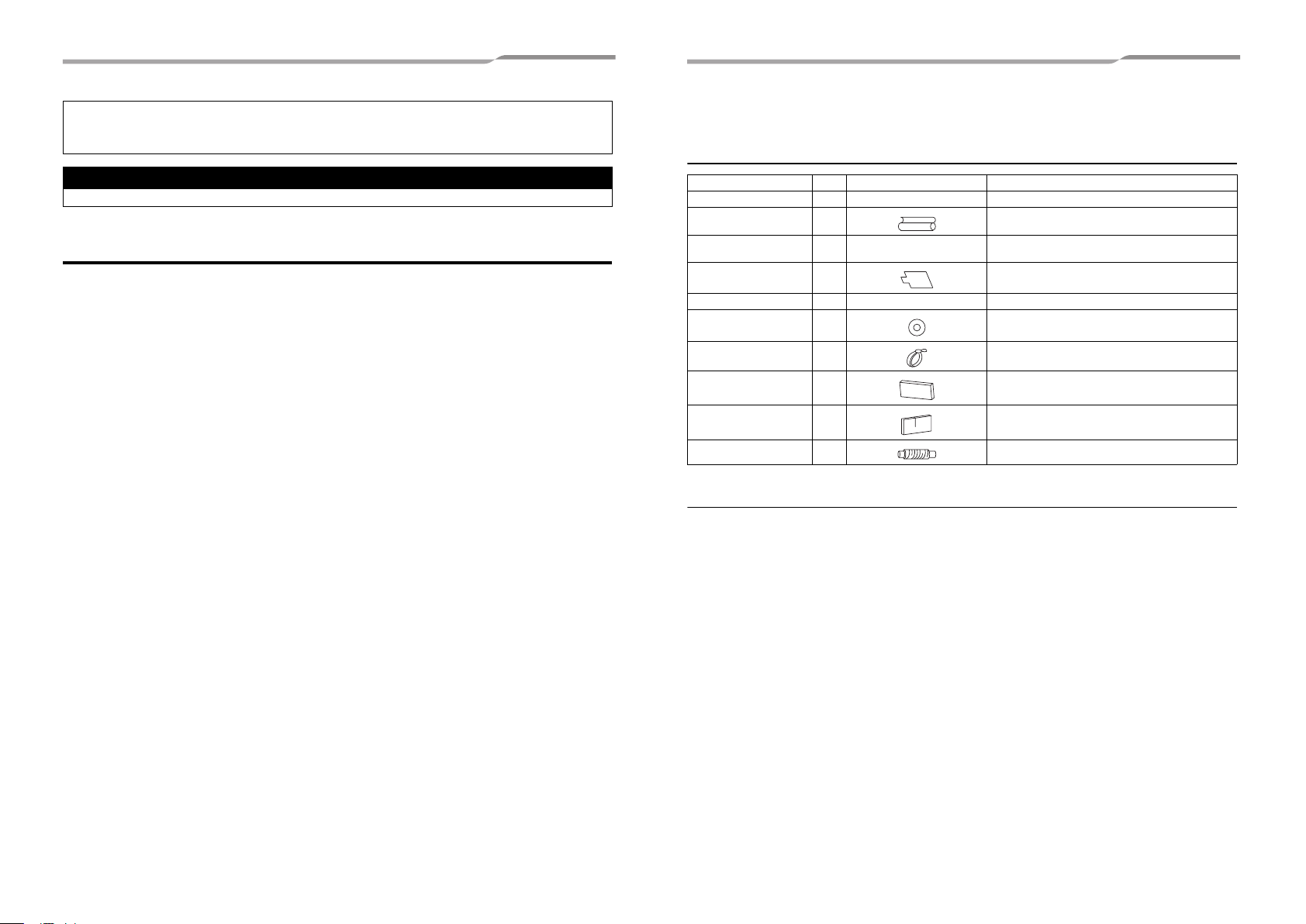
Accessory parts
Part name Q’ty Shape Usage
Installation Manual 1 This manual (Hand over to customers)
Heat insulating pipe 2 For heat insulation of pipe connecting section
Installation pattern 1
Installation gauge 2 For positioning of ceiling position
Pattern fixing screw 4 0.2” (5 mm) × 0.6” (16 mm) For attach the installation pattern
Washer 8 For hanging-down unit
Hose band 1 For connecting drain pipe
Heat insulator 1 For heat insulation of drain connecting section
Heat insulator A 1 For sealing of control wire connecting port
Flexible hose 1 For adjusting center of drain pipe
—
Separate sold parts
• The Ceiling panel and remote control are sold separately. For the installation of these products, follow the
Installation Manuals supplied with them.
For confirmation of ceiling opening and indoor unit
position
1-EN 2-EN
2 Precautions for safety
WARNING
CAUTION
Installing, starting up, and servicing air--conditioning equipment can be hazardous due to system pressures,
electrical components, and equipment location (roofs, elevated structures, etc.).
Only trained, qualified installers and service mechanics should install, start--up, and service this equipment.
Untrained personnel can perform basic maintenance functions such as cleaning heat exchanger. All other
operations should be performed by trained service personnel.
Before working on the equipment, observe precautions in the literature and on tags, stickers, and labels attached
to the equipment.
Follow all safety codes.Wear safety glasses and work gloves. Keep quenching cloth and fire extinguisher nearby
during brazing. Use care in handling, rigging, and setting bulky equipment.
Read these instructions thoroughly and follow all warnings or cautions included in literature and attached to the
unit. Consult local building codes and National Electrical Code (NEC) for special requirements. Recognize safety
information. This is the safety--alert symbol . When you see this symbol on the unit and in instructions or
manuals, be alert to the potential for personal injury.Understand these signal words: DANGER, WARNING, and
CAUTION. These words are used with the safety--alert symbol.
DANGER identifies the most serious hazards which will result in severe personal injury or death. WARNING
signifies hazards which could result in personal injury or death. CAUTION is used to identify unsafe practices which
may result in minor personal injury or product and property damage. NOTE is used to highlight suggestions which
will result in enhanced installation, reliability, or operation.
The manufacturer shall not assume any liability for the damage caused by not observing the description of this
manual.
• Only a qualified installer or service person is allowed to do installation work.
Inappropriate installation may result in water leakage, electric shock or fire.
• Do not use any refrigerant different from the one specified for complement or replacement.
Otherwise, abnormally high pressure may be generated in the refrigeration cycle, which may result in a
failure or explosion of the product or an injury to your body.
• Connect ground wire. (grounding work)
Incomplete grounding may cause an electric shock.
Do not connect ground wires to gas pipes, water pipes, lightning rods or ground wires for telephone wires.
• Turn off all the circuit breaker before attempting any electrical work.
Failure to do so may cause electric shock.
• Install the refrigerant pipe securely during the installation work before operating the air conditioner.
If the air conditioner is operated with the valve open and without the refrigerant pipe, the compressor sucks air and
the refrigeration cycle is overpressurized, which may cause a burst or injury.
• When moving the air conditioner for the installation into another place, do not enter any gaseous matter
other than the specified refrigerant into the refrigeration cycle.
If air or any other gas is mixed in the refrigerant, the gas pressure in the refrigeration cycle becomes abnormally high
and it resultingly causes pipe burst and injuries on persons.
• Perform installation work properly according to the Installation Manual.
Inappropriate installation may result in water leakage, electric shock or fire.
• When the air conditioner is installed in a small room, provide appropriate measures to ensure that the
concentration of refrigerant leakage occur in the room does not exceed the critical level.
• Install the air conditioner securely in a location where the base can sustain the weight adequately.
• Perform the specified installation work to guard against an earthquake.
If the air conditioner is not installed appropriately, accidents may occur due to the falling unit.
• If refrigerant gas has leaked during the installation work, ventilate the room immediately.
If the leaked refrigerant gas comes in contact with fire, noxious gas may generate.
• After the installation work, confirm that refrigerant gas does not leak.
If refrigerant gas leaks into the room and flows near a fire source, such as a cooking range, noxious gas might
generate.
• Electrical work must be performed by a qualified electrician in accordance with the Installation Manual. Use
an exclusive power supply for the air conditioner at the rated voltage.
An insufficient power supply capacity or inappropriate installation may cause fire.
• Use the specified wires for wiring connect the terminals. Securely fix them to prevent external forces applied
to the terminals from affecting the terminals.
• Conform to the regulations of the local electric company when wiring the power supply.
• For the refrigerant recovery work (collection of refrigerant from the pipe to the compressor), stop the
compressor before disconnecting the refrigerant pipe.
If the refrigerant pipe is disconnected while the compressor is working with the valve open, the compressor sucks air
and the refrigeration cycle is overpressurized, which may cause a burst or injury.
• This air conditioner adopts the new HFC refrigerant (R410A) which does not destroy ozone layer.
• The characteristics of R410A refrigerant are; easy to absorb water, oxidizing membrane or oil, and its pressure is
approx. 1.6 times higher than that of refrigerant R22. Accompanied with the new refrigerant, refrigerating oil has also
been changed. Therefore, during insta llation work, be sure that water, dust, former refrigerant, or refrigerating o il does
not enter the refrigerating cycle.
• To prevent charging an incorrect refrigerant and refrigerating oil, the sizes of connecting sections of charging port of
the main unit and installation tools are changed from those for the conventional refrigerant.
• Accordingly the exclusive tools are required for the new refrigerant (R410A).
• For connecting pipes, use new and clean piping designed for R410A, and please care so that water or dust does not
enter.
• Tighten the flare nut with a torque wrench in the specified manner.
Excessive tightening of the flare nut may cause a crack in the flare nut after a long period, which may result in
refrigerant leakage.
• Wear heavy gloves during the installation work to avoid injury.
EN
3-EN 4-EN
–2–
–3–
WARNING
CAUTION
REQUIREMENT
Obstacle
39.4” (1000) or more
39.4” (1000)
or more
11.1” (283) or more
0.6” (15) or more
7.9” (200)
Check port
17.7” (450)
3 Selection of installation place
• Install the air conditioner securely in a location where the base can sustain the weight adequately.
If the strength is not enough, the unit may fall down resulting in injury.
• Install the air conditioner at a height 8’ (2.4 m) or more from the floor.
If you insert your hands or others directly into the unit while the air conditioner operates, it is dangerous because you
may contact with revolving fan or active electricity.
• Do not install in a location where flammable gas may leaks are possible.
If the gas leak and accumulate around the unit, it may ignite and cause a fire.
Upon approval of the customer, install the air conditioner in a place that satisfies the following
conditions.
• Place where the unit can be installed horizontally.
• Place where a sufficient servicing space can be ensured for safety maintenance and check.
• Place where drained water will not cause any problem.
Avoid installing in the following places.
• Place exposed to air with high salt content (seaside area), or place exposed to large quantities of sulfide gas (hot
spring).
(The unit should be used in these places, special protective measures are needed.)
• A restaurant kitchen where a lot of oil is used or place near machines in a factory (Oil adhering to the heat
exchanger and resin part (turbo fan) in the indoor unit may reduce the performance, generate mist or dew drop,
or deform or damage resin parts.)
• Places where iron or other metal dust is present. If iron or other metal dust adheres to or collects on the interior
of the air conditioner, it may spontaneously combust and start a fire.
• Place where organic solvent is used nearby.
• Place close to a machine generating high frequency.
• Place where the discharged air blows directly into the window of the neighbor house. (Outdoor unit)
• Place where noise of the outdoor unit is easily transmitted.
(When the outdoor unit is installed on the boundary with the neighbor, pay due attention to the level of noise.)
• Place with poor ventilation. (Before air duct work, check whether value of fan speed, static pressure and duct
resistance are correct.)
• Do not use the air conditioner for special purposes such as preserving food, precision instruments, or art objects,
or where breeding animals or growing plants are kept. (This may degrade the quality of preserved materials.)
• Place where any of high-frequency appliances (including inverter devices, private power generators, medical
equipment, and communication equipment) and inverter-type fluorescent light is installed.
(A malfunction of the air conditioner, abnormal control, or problems due to noise to such appliances/equipment
may occur.)
• When the wireless remote control is used in a room equipped with an inverter-type fluorescent light or at a place
exposed to direct sunlight, signals from the remote control may not be received correctly.
• Place where organic solvent is used.
• Place near a door or window exposed to humid outside air (Dew drop may form.).
• Place where special spray is used frequently.
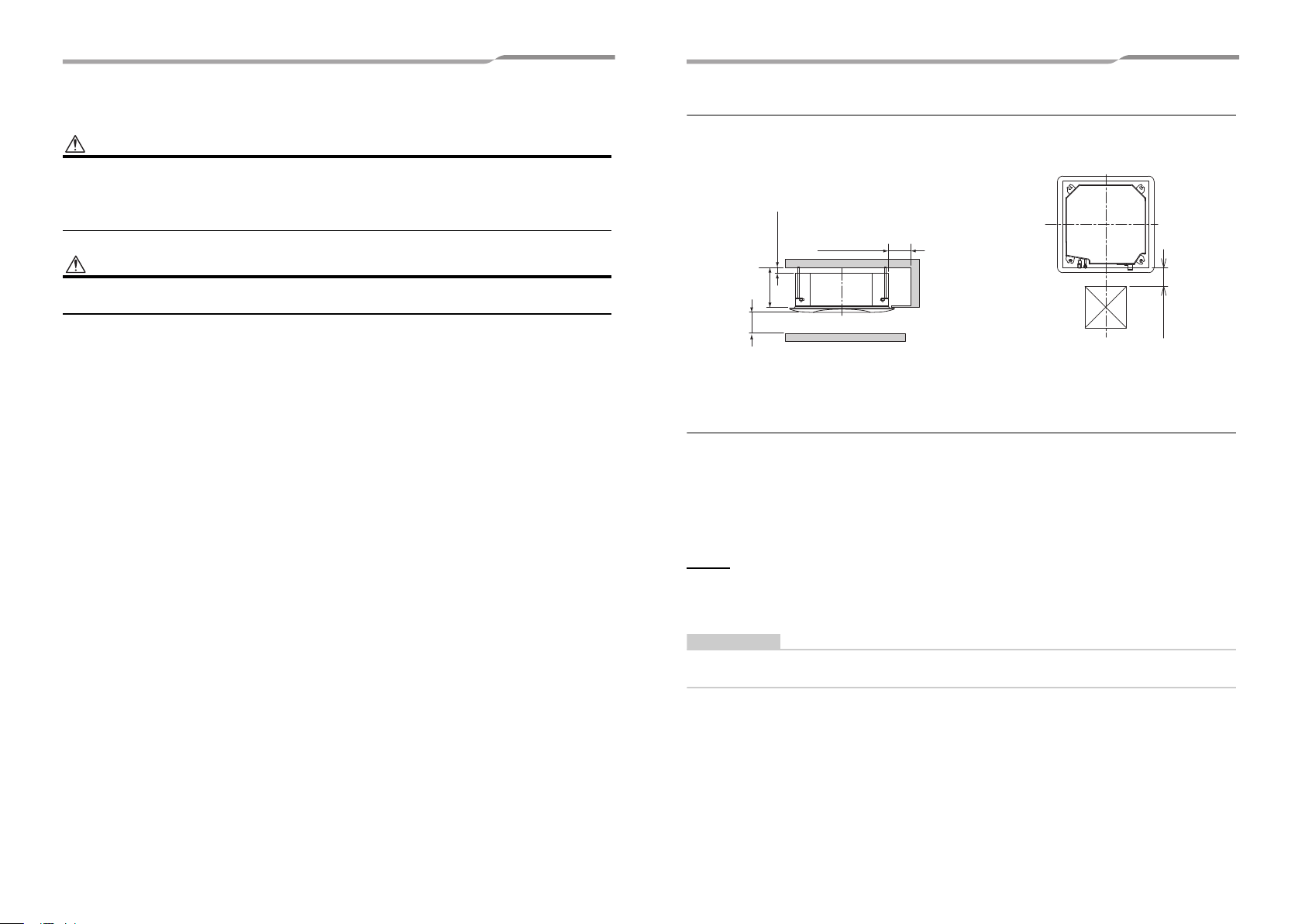
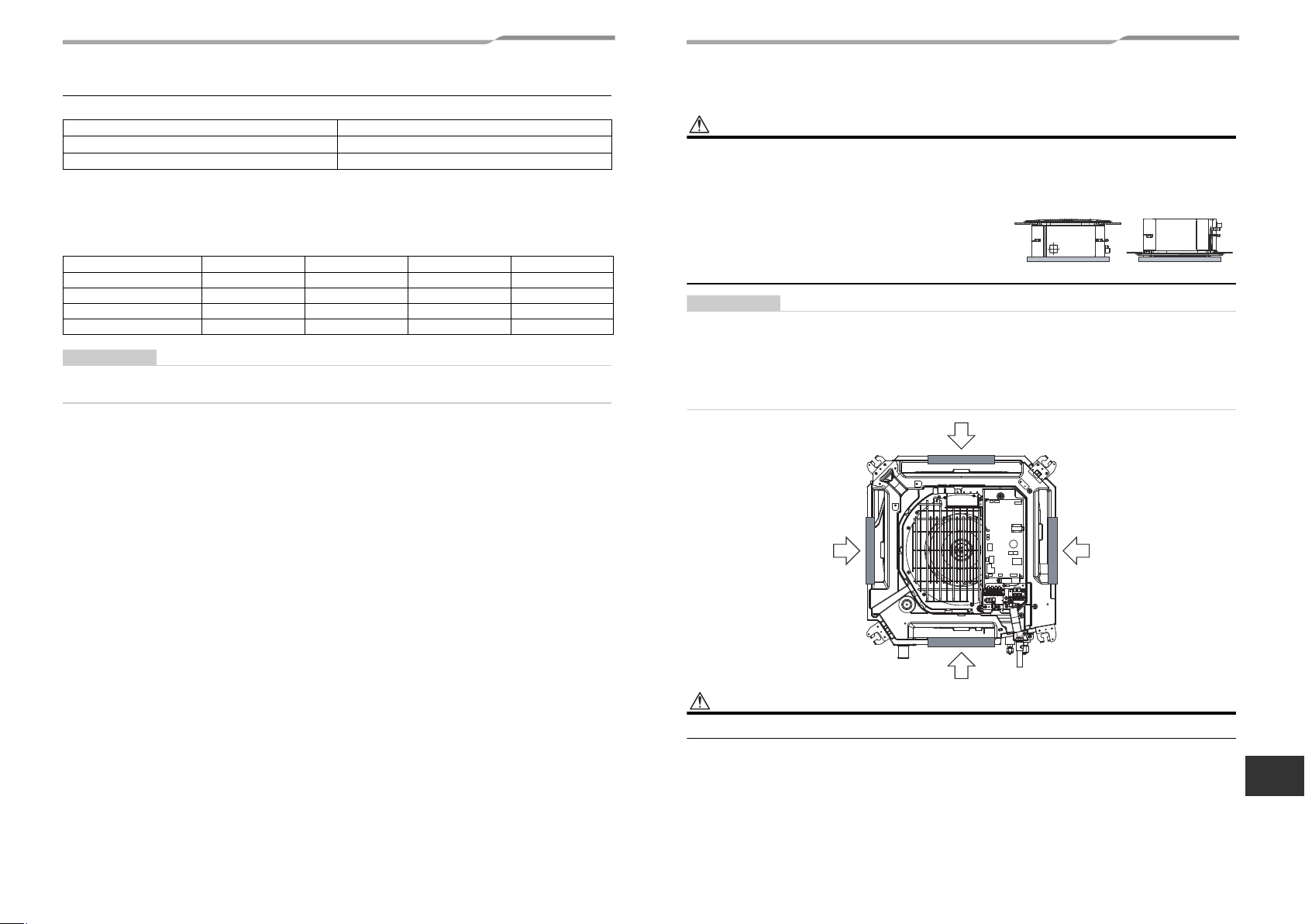
Installation space
Ensure there is sufficient space to install the unit and to perform maintenance work as and when required. Keep
0.6” (15 mm) or more for clearance between top plate of the indoor unit and the ceiling surface.
unit: in (mm)
Selection of installation place
Continual operation of the indoor unit under high-humidity conditions as described below, dew may condense and
water may drop.
Especially, high-humidity atmosphere (dew point temperature: 73.4 °F (23 °C) or more) may generate dew inside
the ceiling.
1. Unit is installed inside the ceiling with slated roof.
2. Unit is installed at a location using inside of the ceiling as fresh air take-in path.
3. Kitchen
Advice
• Set a service check opening panel at right side of the unit (size: 17.7" × 17.7" (450 × 450 mm) or more) for piping,
maintenance, and servicing.
• If installing a unit at such place, put insulating material (glass wool, etc.) additionally on all the positions of the
indoor unit which come to contact with high-humidity atmosphere.
When the humidity inside the ceiling seems to be higher than 80 %, attach a heat insulator to the side (top)
surface of the indoor unit. (Use a heat insulator that is 0.4" (10 mm) or more thick.)
5-EN 6-EN
Ceiling height
REQUIREMENT
WARNING
REQUIREMENT
CAUTION
OK NO GOOD
Model MMU- Installable ceiling height
AP007 to AP012 type Up to 8’10” (2.7 m)
AP015 to AP018 type Up to 11’6” (3.5 m)
When the height of the ceiling exceeds the distance of the item Standard / 4-way in below table, the warm air is
difficult to reach the floor.
It is necessary to change the setup value of the high ceiling setting or discharge direction.
▼ Height list of ceiling possible to be installed
Indoor unit Capacity type AP007 to AP012 type AP015 type AP018 type Setup of high ceiling
Discharge direction 4-way 4-way 4-way Setup data
Standard (factory default) 8’10” (2.7 m) 9’6” (2.9 m) 10’6” (3.2 m) 0000
High ceiling (2) — 10’6” (3.2 m) 11’2” (3.4 m) 0002
High ceiling (3) — 11’6” (3.5 m) 11’6” (3.5 m) 0003
• When high ceiling (2) or (3) is used with 4-way blowing, a draft is easily recognized due to drop of discharge
temperature.
The lighting time of the filter sign (notification of filter cleaning) on the remote control can be changed according to
installation conditions.
When it is difficult to obtain satisfactory heating due to location place of the indoor unit or the structure of the room,
the detection temperature of heating can be raised.
Refer to “8. Applicable controls” in this manual for the setting procedure.
Unit : ft (m)
Unit : ft (m)
4 Installation
The installation of the air conditioning unit must be positioned in a location that can sufficiently support its weight and
give protection against adverse environmental conditions.
Failure to do so may result in unit damage and possible human injury.
Any incomplete installation may also cause possible risk of human injury.
• Unpack the package, take out the product and then place it on the
floor so that the same surface directs underneath as it is placed in
the package.
If the both sides are turned over, a deformation of mounting metal
of the ceiling panel which is sold separately may be caused.
Accordingly the product may be damaged and the installation
becomes impossible in some cases.
Strictly comply with the following rules to prevent damage of the indoor units and human injury.
• Do not put a heavy article on the indoor unit. (Even units are packaged)
• Carry in the indoor unit as it is packaged if possible. If carrying in the indoor unit unpacked by necessity, use buffering
cloth or other soft cloth to not damage the unit.
• To move the indoor unit, hold the hooking metals (4 positions) only.
Do not apply force to the other parts (refrigerant pipe, drain pan, foamed parts, or resin parts).
• Carry the package by two or more persons, and do not bundle it with plastic band at positions other than specified.
Do not tear off the tape adhered to the cabinet; otherwise vibration is caused from the cabinet.
7-EN 8-EN
–4–
EN
–5–
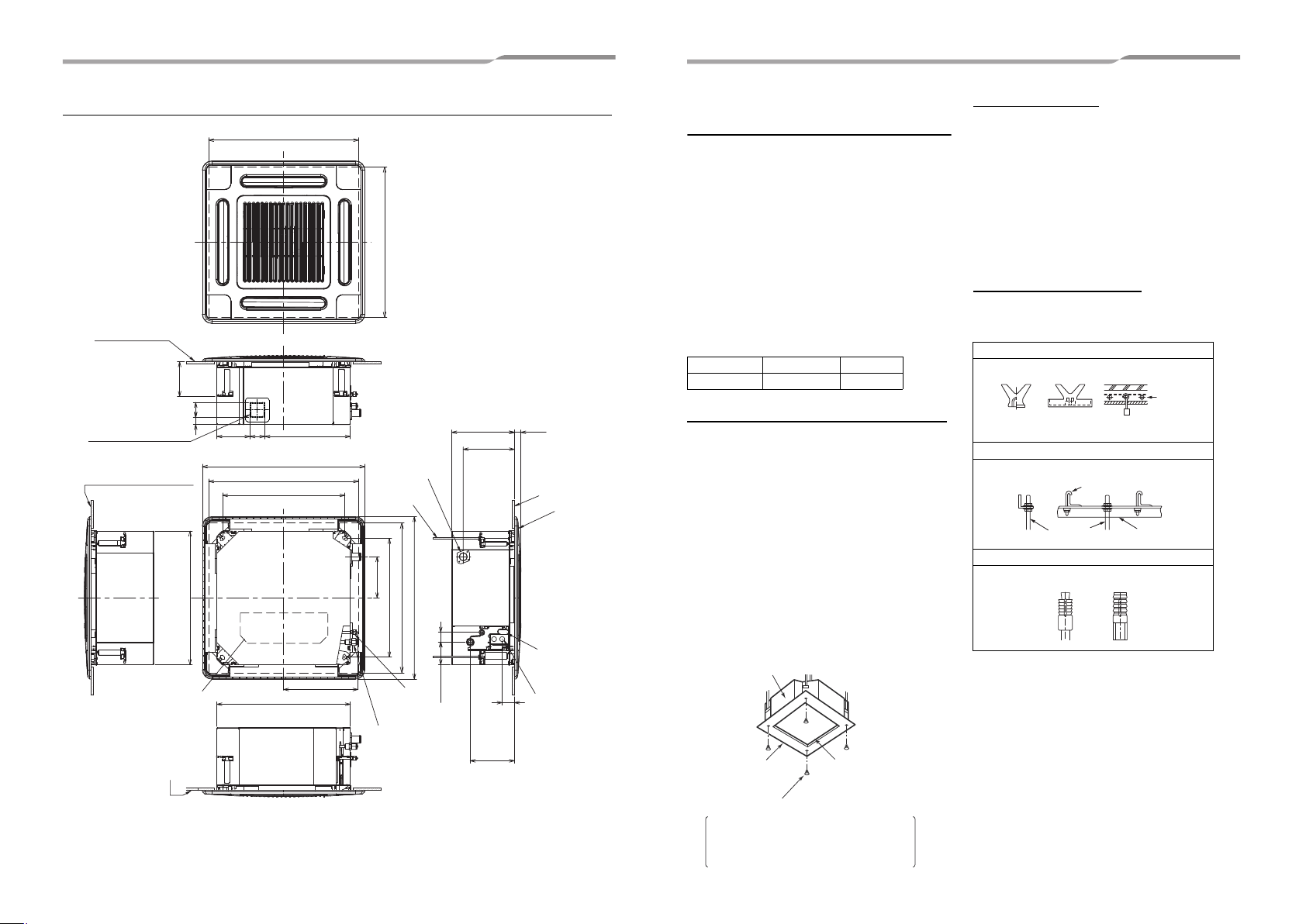
23.4” to 26”(595 to 660) Ceiling open dimension
23.4” to 26”(595 to 660) Ceiling open dimension
5.9”(149)
22.6”(575) Unit external
dimension
Bottom face of ceiling
27.6”(700) Panel external dimension
Electrical control
box
Bottom face
of ceiling
23.4” to 26”(595 to 660) Ceiling open dimension
20.7”(525) Hanging bolt pitch
12.6”(320.5)
7.0”(177)
20.1”(510) Hanging bolt pitch
23.4” to 26”(595 to 660) Ceiling open dimension
27.6”(700) Panel external dimension
22.6”(575) Unit external dimension
Refrigerant
pipe (Liquid)
Ø1/4”(6.4)
Refrigerant pipe (Gas)
AP015, AP018:
Ø1/2”(12.7)
AP007 to AP012:
Ø3/8”(9.5)
Drain pipe
connecting port
Hanging bolt
3/8”(10) local
arrange
10.6”(268) 1.1”(27)
8.7”(220.5)
1.7”(42)3.8”(97.5)
7.5”(190.5)
2.1”
(53)
Wiring connection
port (for control
wiring)
Ceiling panel
Bottom face
of ceiling
Hole for power
supply cable
Knockout for Auxiliary
fresh air flange
For Ø 3.9”(100)
Bottom face of ceiling
2.5”
(64)
1.1”
(29)
5.5”(142) 2.5”
(64)
14.5”(368.5)
Indoor unit
Installation pattern
(Attached)
0.2” (5 mm) × 0.6” (16 mm) screws (Attached)
These screws are exclusive to the installation
pattern. When installing the ceiling panel, the
other exclusive screws attached to the ceiling
panel (sold separately) are used.
Cut off the installation pattern
along slit of the main unit.
Rubber
Anchor bolt
(Blade type
bracket)
(Slide type
bracket)
(Pipe hanging
anchor bolt)
Hanging bolt
Hanging bolt Support angle
External view Unit: in (mm)
Opening a ceiling and
installation of hanging bolts
• Consider the piping / wiring after the unit is hung to
determine the location of the indoor unit installation
and orientation.
• After the location of the indoor unit installation has
been determined, open the ceiling and install
hanging bolts.
• The dimensions of the ceiling opening and hanging
bolt pitches are given in the outline drawing and the
attached installation pattern.
• When a ceiling already exists, lay the drain pipe,
refrigerant pipe, control wires, and remote control
wires to their connection locations before hanging
the indoor unit.
Procure hanging bolts and nuts for installing the indoor
unit (these are not supplied).
Hanging bolt 3/8” (M10) 4 pieces
Nut 3/8” (M10) 12 pieces
Using the installation pattern (accessory)
The installation pattern is provided inside the
packaging cap.
<For existing ceiling>
Use the installation pattern positioning a ceiling
opening and hanging bolts.
<For new ceiling>
Use the installation pattern to position the ceiling
opening when a ceiling is hanged.
• After the hanging bolts have been installed, install
the indoor unit.
• To use the supplied pattern attach it to the indoor unit
using the supplied fixing screws (0.2”(5 mm) ×
0.6”(16 mm) 4 pcs.). (Screw pattern to the ceiling
panel hanging brackets of the indoor unit)
• Before hanging a ceiling, open the ceiling along the
outside dimensions of the installation pattern.
Treatment of ceiling
The ceiling differs according to structure of building.
For details, consult your constructor or interior finish
contractor.
In the process after the ceiling board has been
removed, it is important to reinforce ceiling foundation
(frame) and to keep horizontal level of installed ceiling
correctly in order to prevent vibration of ceiling board.
1. Cut and remove the ceiling foundation.
2. Reinforce the cut surface of ceiling foundation, and
add ceiling foundation for fixing the end of ceiling
board.
Installation of hanging bolt
Use 3/8” (M10) hanging bolts (4 pcs, locally procured).
Matching to the existing structure, set pitch according
to size in the unit external view as shown below.
New concrete slab
Install the bolts with insert brackets or anchor bolts.
Steel flame structure
Use existing angles or install new support angles.
Existing concrete slab
Use a hole-in anchors, hole-in plugs, or a hole-in bolts.
9-EN 10-EN

Installation of ceiling opening and
CAUTION
REQUIREMENT
Hanging bolt
Level
Hanging bracket
Washer (Accessory)
To prevent the bolt
from falling off (for
safety), be sure to set
it just under the
hanging bracket as
shown in the figure.
Eccentric washer
(Accessory)
Nut
3/8” (M10)
Hanging bolt
3/8” (M10)
Nut
3/8” (M10)
* Procure hanging bolts
and nuts locally.
* Install with the marking
“UP” facing up.
Indoor unit
Level vial (levelness: 0.2” (5 mm) or less)
Hanging bolt
Hanging
bracket
Installation gauge
(1) 0.4” - 1.7”
(10 - 42 mm)
Ceiling
board
(2) 0.9” - 1.1”
(23 - 28 mm)
Indoor unit
Installation gauge
(1) 0.4” - 1.7”
(10 - 42 mm)
(2) 0.9” - 1.1”
(23 - 28 mm)
Ceiling board
2
6
.
2
”
(
8
m
)
o
r
l
e
s
s
hanging bolt
Installation of remote control
(Sold separately)
For installation of the wired remote control, follow the
Installation Manual attached with the remote control.
• Pull out the remote control cord together with the
refrigerant pipe or drain pipe.
Pass the remote control cord through upper side of
the refrigerant pipe and drain pipe.
• Do not leave the remote control at a place exposed
to the direct sunlight and near a stove.
• Attach a nut (3/8” (M10): not supplied) and the Ø1.3”
(34 mm) washer (supplied) to each hanging bolt.
• Insert a washer on both sides of the T groove of the
hanging bracket of the indoor unit, and hang the
indoor unit.
• Check that the four sides of the indoor unit are level
using a level vial (levelness: 0.2” (5 mm) or less).
• Detach the installation gauge (accessory) from the
installation pattern.
• Using the installation gauge, check and adjust the
positional relation between the indoor unit and the
ceiling opening (1) (0.4” - 1.7” (10 - 42 mm): 4 sides)
and the hanging-up height (2) (0.9” - 1.1” (23 - 28
mm): 4 corners).
(How to use the installation gauge is printed on the
gauge.)
Before installation of the indoor unit, remove the tape
that holds the fan and bell mouth. Running the unit
without removing the tape may damage the fan motor.
Wireless remote control
The sensor of indoor unit with wireless remote control
can receive a signal by distance within approx. 26.2” (8
m). Based upon it, determine a place where the remote
control is operated and the installation place.
• Operate the remote control, confirm that the indoor
unit receives a signal surely, and then install it.
• Keep 3’3” (1 m) or more from the devices such as
television, stereo, etc.
(Disturbance of image or noise may generate.)
• To prevent a malfunction, select a place where is not
influenced by a fluorescent light or direct sunlight.
• Two or more (Up to 6 units) indoor units with wireless
type remote control can be installed in the same
room.
Installation of ceiling panel
(sold separately)
Install the ceiling panel according to Installation
Manual attached with it after piping / wiring work has
completed.
Check that installation of indoor unit and ceiling
opening part is correct, and then install it.
• Joint the connecting sections of ceiling panel, ceiling
surface, ceiling panel and indoor unit closely.
Any gap between them will cause air leakage and the
generate condensation or water leakage.
• Remove the adjust corner caps at the four corners of
11-EN 12-EN
the ceiling panel, and then install the ceiling panel
onto the indoor unit.
–6–
EN

–7–
CAUTION
REQUIREMENT
OK NO GOOD
Max
45°
Max
45°
90° Bend
Riser (Trap)
Support
bracket
1/100 or more
downward
Heat insulator
4’11” - 6’7” (1.5 - 2 m)
Arched
shape
Trap
NO
GOOD
VP25
As long as possible (3.9” (100 mm))
Downward slope
1/100 or more
VP30 or more
VP25 VP25
REQUIREMENT
CAUTION
Drain pipe
connecting
port
Align the attached
hose band to the end
of hose, set the
tightening position
upward, and then
tighten it.
VP25 vinyl chloride
pipe
(Locally procured)
Socket for VP25
(Locally procured)
Hard socket
Soft socket
Adhesive agent
prohibited
Flexible
drain hose
Hose band
Indoor unit
10 to 12 mm
15 mm or less
10 mm
Rising up 24.7”
(627.5 mm) or less
Underside of ceiling
Indoor unit
11.8” (300 mm)
or less
Rising up 33.5” (850 mm) or less
5 Drain piping work
• Following the Installation Manual, perform the
drain piping work so that water is properly
drained, and apply a heat insulation so as not to
cause a dew drop.
Inappropriate piping work may result in water
leakage in the room and wet of furniture.
Piping / Heat insulating
material
Require the following materials for piping and heat
insulating at site.
Piping
Heat insulator
Flexible hose
Use the attached flexible hose to adjust center
discrepancy of the hard vinyl chloride pipe or to adjust
the angle.
• Do not use the flexible hose as stretched, or do not
deform it more extent than that in the following figure.
• Fix the soft end of the flexible hose with the attached
hose band.
• Use the flexible hose on a horizontal level.
Hard vinyl chloride pipe VP25
(Outer dia.: Ø1.3” (32 mm))
Foam polyethylene:
Thickness 0.4” (10 mm) or more
• Perform heat insulation of the drain pipes of the indoor
unit.
• Perform heat insulation of the connecting part with the
indoor unit.
An incomplete heat insulation causes dew drop.
• Set the drain pipe with downward slope (1/100 or
more), and do not make swelling or trap on the piping.
It may cause an abnormal sound.
• For length of the traversing drain pipe, restrict to 65’7”
(20 m) or less.
In case of a long pipe, provide support brackets with
interval of 4’11” - 6’7” (1.5 - 2 m) in order to prevent
waving.
• Set the collective piping as shown in the below figure.
• Do not apply force to the connecting part of the drain
pipe.
• The hard vinyl-chloride pipe cannot be directly
connected to the drain pipe connecting port of the
indoor unit.
For connection with the drain pipe connecting port, fix
the attached flexible hose with the hose band,
otherwise a damage or water leak is caused on the
drain pipe connecting port.
• Adhesive agent cannot be used for the pipe
connecting port (hard socket) of the indoor unit.
Be sure to use the attached hose band for fixing,
otherwise damage or water leakage of the drain pipe
connecting port is caused.
Connecting drain pipe
• Connect a hard socket (locally procured) to the hard
socket of the attached supplied flexible hose.
• Connect a drain pipe (locally procured) to the
connected hard socket.
• Connect hard vinyl chloride pipes securely using an
adhesive for vinyl chloride to avoid water leakage.
• It takes some time until the adhesive is dried and
hardened (refer to the manual of the adhesive). Do not
apply stress to the joint with the drain pipe during this
time period.
Drain up
When a down-gradient cannot be secured for the
drainpipe, drain-up piping is possible.
• The height of the drain pipe must be 33.5" (850 mm)
or less from the bottom of the ceiling.
• Take the drain pipe out of the drain pipe joint with the
indoor unit in 11.8" (300 mm) or less, and bend up
the pipe vertically.
• Immediately after the pipe is bent up vertically, lay
the pipe making a down-gradient.
• Set downward grading immediately after raising up
vertically.
Check the draining
In the test run, check that water drain is properly
performed and water does not leak from the connecting
part of the pipes.
Check draining also when installed in heating period.
By using a pitcher or hose, pour water (0.4 - 0.5 gal
(1500 - 2000 cc)) into the discharge port before
installation of the ceiling panel.
Pour water gradually so that water does not spread on
the motor of the drain pump.
Pour water gently so that it does not spread around
inside the indoor unit, which may cause a malfunction.
13-EN 14-EN

Air discharge
area
Insert the leading part of the hose
between the heat exchanger and
the drain pan, and then bend it
downward.
Polyethylene hand
pump for pouring
water in drain pan
Water (0.4-0.5 gal
(1500 cc to 2000 cc))
Vessel
Drain pan
L1L
2
Pull out connector CN34 (Red)
from P.C. board.
CN34
(RED)
Black
Black
Red
White
Power
terminals
208/230-1-60
Wrap the attached heat insulator seamlessly from
the surface of the indoor unit.
Flexible hose
Hose band
Attached heat
insulator
Heat insulator to be
procured locally
Hard vinyl chloride pipe
6 Refrigerant piping and evacuation
REQUIREMENT
CAUTION
B
A
• After the electric work has finished, pour water
during COOL mode operation.
• If the electric work has not yet finished, pull out the
float switch connector (CN34: Red) from the
electrical control box, and check draining by plugging
the single phase 208/230 V power to the terminal
1 and L2.
blocks L
If doing so, the drain pump motor operates.
• Test water drain while checking the operation sound
of the drain pump motor.
(If the operation sound changes from continuous
sound to intermittent sound, water is normally
drained.)
After the check, the drain pump motor runs,
connecting the float switch connector.
(In case of check by pulling out the float switch
connector, be sure to return the connector to the
original position.)
Perform heat insulating
• As shown in the figure, cover the flexible hose and
hose band with the attached heat insulator up to the
bottom of the indoor unit without gap.
• Cover the drain pipe seamlessly with a heat insulator
to be procured locally so that it overlaps with the
attached heat insulator of the drain connecting
section.
* Direct the slits and seams of the heat insulator
upward to avoid water leakage.
Refrigerant piping
1. Use copper pipe with 0.03” (0.8 mm) or more
thickness.
2. Flare nut and flare works are also different from
those of the conventional refrigerant.
Take out the flare nut attached to the main unit of the
air conditioner, and use it.
When the refrigerant pipe is long, provide support
brackets at intervals of 8’2” - 9’10” (2.5 - 3 m) to clamp
the refrigerant pipe. Otherwise, abnormal sound may be
generated.
IMPORTANT 4 POINTS FOR PIPING WORK
1. Remove dust and moisture from the inside of the
connecting pipes.
2. Tight connection (between pipes and unit)
3. Evacuate the air in the connecting pipes by using
VACUUM PUMP.
4. Check the gas leakage. (Connected points)
Pipe size
Model
name
Pipe size
MMU-
Gas side
Liquid side
AP007, AP009,
AP012 type
3/8”
(9.5 mm)
1/4”
(6.4 mm)
AP015, AP018
type
1/2”
(12.7 mm)
1/4”
(6.4 mm)
Permissible piping length and
height difference
They vary according to the outdoor unit.
For details, refer to the Installation Manual attached to
the outdoor unit.
Flaring
• Cut the pipe with a pipe cutter.
Remove burrs completely.
Remaining burrs may cause gas leakage.
• Insert a flare nut into the pipe, and flare the pipe.
As the flaring sizes of R410A differ from those of
refrigerant R22, the flare tools newly manufactured
for R410A are recommended.
However, the conventional
tools can be used by adjusting
projection margin of the
copper pipe.
▼ Projection margin in
flaring: B (Unit: in (mm))
Rigid (Clutch type)
R410A tool
Outer dia. of copper pipe
1/4” (6.4), 3/8” (9.5)
1/2” (12.7)
used
R410A R410A
0 - 0.02”
(0 - 0.5)
▼ Flaring dia. meter size: A (Unit: in (mm))
Outer dia. of copper pipe
1/4” (6.4) 0.36” (9.1)
3/8” (9.5) 0.52” (13.2)
1/2” (12.7) 0.65” (16.6)
* In case of flaring for R410A with the
conventional flare tool, pull it out approx.
0.02" (0.5 mm) more than that for R22 to
adjust to the specified flare size.
The copper pipe gauge is useful for
adjusting projection margin size.
Conventional
tool used
0.04” - 0.06”
(1.0 - 1.5)
+0
A
–0.02 (0.4)
R410A
15-EN 16-EN
–8–
EN

–9–
CAUTION
REQUIREMENT
REQUIREMENT
REQUIREMENT
Work using double spanner
Indoor unit
Union
Heat insulation
pipe
(Accessory)
Flare nut
Heat insulator
of the pipe
Wrap the pipe with the attached heat insulator
without any gap between the indoor unit.
The seam must be faced upward
(ceiling side).
Banding band
(locally
procured)
WARNING
CAUTION
REQUIREMENT
Tightening connection
• Do not apply excessive torque. Otherwise, the nut
may crack depending on the conditions.
Unit: ft•lbs (N•m)
Outer dia. of copper pipe Tightening torque
1/4” (6.4 mm) 10 - 13 (14 - 18)
3/8” (9.5 mm) 24 - 31 (33 - 42)
1/2” (12.7 mm) 37 - 46 (50 - 62)
▼
Tightening torque of flare pipe connections
Pressure of R410A is higher than that of R22.
(Approx. 1.6 times) Use a torque wrench, tighten the
flare pipe connecting sections which connect the
indoor and outdoor units of the specified tightening
torque.
Incorrect connections may cause not only a gas leak,
but also a trouble of the refrigeration cycle.
Align the centers of the connecting pipes and tighten
the flare nut as far as possible with your fingers. Then
tighten the nut with a spanner and torque wrench as
shown in the figure.
Tightening with an excessive torque may crack the nut
depending on installation conditions.
Tighten the nut within the specified tightening torque.
Piping with outdoor unit
• Shape of valve differs according to the outdoor unit.
For details of installation, refer to the Installation
Manual of the outdoor unit.
Leak check test, evacuation
and other procedure
For leak check test, evacuation, addition of refrigerant,
and gas leak check, refer to the Installation Manual
attached to the outdoor unit.
Do not supply power to the indoor unit until the leak
check test and evacuation are completed. (If the indoor
unit is powered on, the pulse motor valve is fully closed,
which extends the time for vacuuming.)
Open the valve fully
Open the valve of the outdoor unit fully.
For details, refer to the Installation Manual attached to
the outdoor unit.
Heat insulation process
Apply heat insulation for the pipes separately at liquid
side and gas side.
For the heat insulation to the pipes at gas side, use the
material with heat-resisting temperature 248 °F (120
°C) or higher.
Apply the attached heat insulation to the pipe
connecting section of the indoor unit securely without
gap.
• Apply the heat insulation to the pipe connecting
section of the indoor unit securely up to the root
without exposure of the pipe. (The pipe exposed to the
outside may causes water leak.)
• Wrap heat insulator with its slits facing up (ceiling
side).
7 Electrical connection
1. Use predefined wire and connect them certainly.
Keep the connecting terminal free from external
force.
Improper wire connection or clamping may result in
exothermic, fire or malfunction.
2. Connect ground wire. (grounding work)
Incomplete grounding cause an electric shock.
Do not connect ground wires to gas pipes, water
pipes, lightning rods or ground wires for telephone
wires.
3. Install appliance in accordance with national
wiring regulations.
Capacity shortage of circuit breaker or incomplete
installation may cause an electric shock or a fire.
• Consult local building codes, NEC (National Electrical
Code) or CEC (Canadian Electrical Code) for special
requirements.
• If incorrect / incomplete wiring is carried out, it will
cause an electrical fire or smoke.
• Install circuit breaker is not tripped by shock waves.
If circuit breaker is not installed, an electric shock may
be caused.
• Use the cord clamps attached to the product.
• Do not damage or scratch the conductive core and
inner insulator of power and control wires when
peeling them.
• Use the power cord and control wire of specified
thickness, type, and protective devices required.
• Do not connect 208/230 V power to the terminal
blocks (U1, U2, A, B etc.) for control wiring.
(Otherwise, the system will fail.)
• Perform the electric wiring so that it does not come to
contact with the high-temperature part of the pipe.
The coating may melt resulting in an accident.
• Do not turn on the circuit breaker of the indoor unit
until vacuuming of the refrigerant pipes completes.
• For power supply wiring, strictly conform to the Local
Regulation in each country.
• Run the refrigerant piping line and control wiring line in
the same line.
Power supply wire and
control wires specifications
Power supply wire and control wires are procured
locally.
For the power supply specifications, follow to the table
below. If capacity is little, it is dangerous because
overheat or seizure may be caused.
Indoor unit power supply
• For the power supply of the indoor unit, prepare the
exclusive power supply separated from that of the
outdoor unit.
▼ Power supply
Power supply 208/230-1-60
Control wiring, Central control wiring
• 2-core with non-polarity wires are used for the
control wiring between indoor unit and outdoor unit
and Central control wiring.
• To prevent noise trouble, use 2-core shielded wire.
• The length of the communication line means the total
length of the control wire length between indoor and
outdoor units added with the central control wire
length.
17-EN 18-EN

Power supply wire
NOTE
CAUTION
Indoor unit
Remote control inter-unit wiring
Indoor unit Indoor unit Indoor unit
Remote
control
(Max. 8 units)
Remote
control
wiring
NOTE
U1U2
U1U2U3U4L1 L2L3 N U5U6
L1L2 A BU1U2L1L2 A B U1U2L1L2 A B U1U2L1L2 A B
A B
U1U2U3U4L1 L2L3 N U5U6
A B A B
Outdoor Power supply
Ground
terminal
Ground
terminal
Outdoor Power supply
Circuit breaker Circuit breaker
Header outdoor unit
Follower outdoor unit
Control wiring between outdoor units
Control wiring between indoor and outdoor units
Control wiring between indoor units
Indoor unit
Indoor unit Indoor unit
Indoor unit
Ground Ground Ground Ground
Remote
control
Remote
control
Remote
control
Indoor
power
supply
Circuit
breaker
208/230-3-60
208/230-3-60
208/2301-60
Disconnect
switch per NEC
Disconnect
switch per
NEC
Disconnect
switch per
NEC
Disconnect
switch per
NEC
Group control
• Recommended wire diameter and wire length for power supply wire.
Power supply wiring
▼ Electric characteristics
Model Power Supply
MMU-AP0071MH2UL
MMU-AP0091MH2UL 0.5 15
MMU-AP0121MH2UL 0.5 15
MMU-AP0151MH2UL 0.7 15
MMU-AP0181MH2UL 0.7 15
208/230 V-1-60 Hz 187 253
Wire size: 2 × AWG12
Ground 1 × AWG12 or thicker
MOCP : Maximum Overcurrent Protection (Amps)
Up to 164’1” (50 m)
MCA : Minimum Circuit Amps
Voltage Range (V) MCA MOCP
Min Max (A) (A)
0.5 15
Control wire
Control wiring between indoor units, and outdoor unit (2-core
shielded wire)
Wire size
(Up to 3280’10” (1000 m)) AWG16
(Up to 6561’8” (2000 m)) AWG14
Remote control wiring
• 2-core with non-polarity wire is used for wiring of the remote control wiring and group remote controls wiring.
Remote control wiring, remote control inter-unit wiring Wire size: AWG20
Total wire length of remote control wiring and remote control
inter-unit wiring = L + L1 + L2 + … Ln
Total wire length of remote control inter-unit wiring = L1 + L2 + … Ln Up to 656’2” (200 m)
In case of wired type only Up to 1640’5” (500 m)
In case of wireless type included Up to 1312’4” (400 m)
Wiring between indoor and outdoor units
An outdoor unit connected with control wiring between indoor and outdoor units wire becomes automatically the header
unit.
▼ Wiring example
L
• Use copper supply wire.
• Use UL wire rated 600 V for the power supply.
• Use UL wire rated 300 V for the remote control wires and control wires.
The remote control wire (Communication line) and AC208 / 230 V wires cannot be parallel to contact each other and
cannot be stored in the same conduits. If doing so, a trouble may be caused on the control system due to noise or other
factor.
19-EN 20-EN
L1
L2 Ln
–10–
EN

–11–
REQUIREMENT
Screw
Cover of
electrical
control box
Electrical control box
Screw
Wire cover
Conduit plate B
Screw
Conduit plate A
Screw
Lock nut
Conduit plate
A
Conduit pipe
Adhered surface
Slit section
Heat insulator A
Ground screw
for shielded wire
Power supply
terminal block
Control wire
(2-core shielded wire)
Control wire
connecting port
Control wire /
Remote control
terminal block
Cord clamp
Ground screw
CAUTION
L1 L2
0.8” (20)
1.2” (30)
0.4” (10)
Ground wire
0.08” (2) or less
Power supply wires and control
wire
Cord Clamp
5P connector (White)
Wire from ceiling panel
Wire connection
• Connect the wires matching the terminal numbers. Incorrect connection causes a trouble.
• Route the wire through the wire connection port of the indoor unit.
• The low-voltage circuit is provided for the control wire and remote control wire. (Do not connect the high-voltage
circuit.)
• Remove the cover of the electrical control box by removing the mounting screws (3 positions) and push the
hooking section. (The cover of the electrical control box remains hanged to the hinge.)
• Remove the wire cover by removing the mounting screws. (1 position)
• Remove the conduit plate B by removing the mounting screws. (1 position)
• Attach the conduit pipe to the conduit plate A with a lock nut.
• Tighten the screws on the terminal block and secure the wires with cord clamp fitted to the electrical control box.
(Do not apply tension to the connecting section of the terminal block.)
• Use the supplied heat insulation for the sealing of the control wire connecting port. (Otherwise dew condensation
may be caused.)
• Mount the conduit plate B, the wire cover and the cover of the electrical control box ensuring the wires are not
pinched. (Mount the conduit plate B, the wire cover and the cover after the ceiling panel has been wired to the
electrical control box.)
Power supply wires and
ground wire
1. Strip the wire ends.
Power supply wire: 0.4” (10 mm)
Ground wire: 0.8” (20 mm)
2. Match the wire colors with the terminal numbers on
the indoor units’ and circuit breakers’ terminal blocks
and firmly screw the wires to the corresponding
terminals.
3. Secure the ground wire with the ground screw.
4. Fix the wires with a cord clamp.
Unit: in (mm)
Firmly tighten the screws of the terminal block.
Keep the wire length as shown in figure below when it
is connected to the terminal block.
Wiring on the ceiling panel
According to the Installation Manual of the ceiling
panel, connect the connector (2P: Red) of the ceiling
panel to the connector (5P: White) on P.C. board of the
electrical control box.
Address setup
Set up the addresses as per the Installation Manual
supplied with the outdoor unit.
21-EN 22-EN
U1U2A B
L1L2L1L
2

8 Applicable controls
REQUIREMENT
1
6
1
3
2
5
4
(* Display content varies with the
indoor unit model.)
Short Open
CN112 CN111 CN110
CN112 CN111 CN110
CN112 CN111 CN110
When the air conditioner is used for the first time, it will
take some moments after the power has been turned on
before the remote control becomes available for
operations: This is normal and is not indicative of trouble.
• Concerning the automatic addresses (The automatic
addresses are set up by performing operations on the
outdoor interface circuit board.)
While the automatic addresses are being set up, no
remote control operations can be performed. Setup
takes up to 10 minutes (usually about 5 minutes).
• When the power is turned on after automatic address
setup
It takes up to 10 minutes (usually about 3 minutes) for
the outdoor unit to start operating after the power has
been turned on.
Before the air conditioner was shipped from the factory,
all units are set to [STANDARD] (factory default). If
necessary, change the indoor unit settings.
The settings are changed by operating the wired remote
control.
* The settings cannot be changed using only a wireless
remote control, simple remote control or group control
remote control by itself so install a wired remote
control separately as well.
Changing applicable control
setting
Basic procedure for changing settings
Change the settings while the air conditioner is not
working.
(Stop the air conditioner before making settings.)
1 Push button and temp. setup button
simultaneously for 4 seconds or more.
After a while, the display flashes as shown in the
figure.
Confirm that the CODE No. is [01].
• If the CODE No. is not [01], push button to
erase the display content, and repeat the
procedure from the beginning.
(No operation of the remote control is accepted
for a while after button is pushed.)
(While air conditioners are operated under the
group control, “ ” is displayed first.
When button is pushed, the indoor unit
number displayed following “ALL” is header
unit.)
3 Specify CODE No. [ ] with temp. setup
/ buttons.
4 Select SET DATA [ ] with timer time
/ buttons.
5 Push button. When the display changes
from flashing to lit, the setup is completed.
• To change settings of another indoor unit,
repeat from Procedure
• To change other settings of the selected indoor
unit, repeat from Procedure
Use button to clear the settings.
To make settings after button was pushed,
repeat from Procedure
2.
3.
2.
6 When settings have been completed, push
button to determine the settings.
When button is pushed, “SETTING” flashes
and then the display content disappears and the
air conditioner enters the normal stop mode.
(While “SETTING” is flashing, no operation of the
remote control is accepted.)
Installing indoor unit on high
ceiling
When an indoor unit is installed on a ceiling higher than
the standard height, make the high-ceiling setting for
fan speed adjustment.
Follow to the basic operation procedure
1 → 2 → 3 → 4 → 5 → 6 ).
(
• For the CODE No. in Procedure
• Select the SET DATA for Procedure
“Height list of ceiling possible to be installed” table on
page 4 in this manual.
3, specify [5d].
4 from the
Remote control-less setting
To set the unit to high ceiling setting, there is a method
that requires the changing of the short plugs on the
indoor P.C. board. The details are shown in the below
table.
This method is only to be used where a wired remote
control (Group control) is not used.
* However, once the setting is changed, it is
necessary to reset the setting back to 0000 that
placing the short plugs back to the factory default
position and rewriting the setting data back to 0000
with wired remote control. (The setting can be
changed to 0001 and 0003 without resetting.)
• Select by exchange of short plugs on indoor P.C.
board.
Short plug position
SET
DATA
0000 Standard (Factory default)
0002 High ceiling (2)
0003 High ceiling (3)
• Short plugs position (CN112, CN111, CN110 from
the left)
Note
2 Each time button is pushed, indoor
unit numbers in the control group change
cyclically. Select the indoor unit to change
settings for.
The fan of the selected unit runs and the louvers
start swinging. The indoor unit can be confirmed
for which to change settings.
23-EN 24-EN
–12–
EN

–13–
CAUTION
2, 4
3
1,5
Filter sign setting
According to the installation condition, the lighting time
of the filter sign (Notification of filter cleaning) can be
changed.
Follow to the basic operation procedure
1 → 2 → 3 → 4 → 5 → 6 ).
(
• For the CODE No. in Procedure
• For the [Set data] in Procedure
DATA of filter sign lighting time from the following
table.
SET DATA Filter sign lighting time
0000 None
0001 150 H
0002 2500 H (Factory default)
0003 5000 H
0004 10000 H
3, specify [01].
4, select the SET
To secure better effect of
heating
When it is difficult to obtain satisfactory heating due to
installation place of the indoor unit or structure of the
room, the detection temperature of heating can be
raised. Also use a circulator or other device to circulate
heat air near the ceiling.
Follow to the basic operation procedure
1 → 2 → 3 → 4 → 5 → 6 ).
(
• For the CODE No. in Procedure
• For the set data in Procedure
DATA of shift value of detection temperature to be
set up from the table below.
SET DATA Detection temp shift value
0000 No shift
0001 +1.8 °F (+1 °C)
0002
0003 +5.4 °F (+3 °C)
0004 +7.2 °F (+4 °C)
0005 +9.0 °F (+5 °C)
0006 +10.8 °F (+6 °C)
+3.6 °F (+2 °C)
(Factory default)
3, specify [06].
4, select the SET
Remote control sensor
The temperature sensor of the indoor unit senses room
temperature usually. Set the remote control sensor to
sense the temperature around the remote control.
Select items following the basic operation procedure
1 → 2 → 3 → 4 → 5 → 6 ).
(
• Specify [32] for the CODE No. in Procedure
• Select the following data for the SET DATA in
Procedure
SET DATA 0000 0001
Remote control
sensor
When flashes, the remote control sensor is
defective.
Select the SET DATA [0000] (not used) or replace the
remote control.
4.
(factory default)
Not used
3.
Used
Group control
In a group control, a remote control can control up to
maximum 8 units.
• The wired remote control only can control a group
control. The wireless remote control is unavailable
for this control.
• For wiring procedure and wires of the individual line
(Identical refrigerant line) system, refer to “Electric
work” in this Manual.
• Wiring between indoor units in a group is performed
in the following procedure.
• Connect the indoor units by connecting the remote
control wires from the remote control terminal blocks
(A, B) of the indoor unit connected with a remote
control to the remote control terminal blocks (A, B) of
the other indoor unit. (Non-polarity)
• For address setup, refer to the Installation Manual
attached to the outdoor unit.
9 Test run
Before test run
• Before turning on the circuit breaker, carry out the
following procedure.
1) By using 500 V-megger, check that resistance of
1MΩ or more exists between the terminal block
L
1 to L2 and the ground (grounding).
If resistance of less than 1 MΩ is detected, do not
run the unit.
2) Check the valve of the outdoor unit being opened
fully.
• To protect the compressor at activation time, leave
power-ON for 12 hours or more be for operating.
• Before starting a test run, be sure to set addresses
following the Installation Manual supplied with the
outdoor unit.
Execute a test run
Operate the unit with the remote control as usual.
For the procedure of the operation, refer to the
attached Owner’s Manual.
A forced test run can be executed in the following
procedure even if the operation stops by thermo.-OFF.
In order to prevent a serial operation, the forced test
run is released after 60 minutes have passed and
returns to the usual operation.
• Do not use the forced test run for cases other than the
test run because it applies an excessive load to the
devices.
Wired remote control
2 Push button.
3 Select the operation mode with
button, [COOL] or [HEAT].
• Do not run the air conditioner in a mode other
than [COOL] or [HEAT].
• The temperature controlling function does not
work during test run.
• The detection of error is performed as usual.
4 After the test run, push button to
stop a test run.
(Display part is same as procedure 1.)
5 Push check button to cancel (release
from) the test run mode.
([TEST] disappears on the display and the status
returns to a normal.)
1 Push button for 4 seconds or more.
[TEST] is displayed on the display part and
the selection of mode in the test mode is
permitted.
25-EN 26-EN

Wireless remote control
Small
screw
Nameplate
Notch
M4 × 25 screw
(2 pieces)
Spacer
Receiver unit
REQUIREMENT
Check code Indoor UNIT No. in
which an error occurred
1 Remove a small screw which fixes the
nameplate of the receiver unit.
Remove the nameplate of the sensor section by
inserting a minus screwdriver, etc into the notch at
the bottom of the plate, and set the Dip switch to
[TEST RUN ON].
2 Execute a test operation with ON/OFF
button on the wireless remote control.
• , , and LED flash during test operation.
• Under status of [TEST RUN ON], the
temperature adjustment from the wireless
remote control is invalid.
Do not use this method in the operation other than
test operation because the equipment is
damaged.
3 Use either COOL or HEAT operation mode
for a test operation.
* The outdoor unit does not operate approx. 3
minutes after power-ON and operation stop.
4 After the test operation finished, stop the air
conditioner from the wireless remote
control, and return Dip switch of the receiver
section as before.
(A 60-minutes timer clearing function is attached
to the receiver section in order to prevent a
continuous test operation.)
10Troubleshooting
Confirmation and check
When an error occurred in the air conditioner, the
check code and the indoor UNIT No. appear on the
display part of the remote control.
The check code is only displayed during the operation.
If the display disappears, operate the air conditioner
according to the following “Confirmation of error log” for
confirmation.
Confirmation of error log
When an error occurred on the air conditioner, the error
log can be confirmed with the following procedure.
(The error log is stored in memory up to 4 errors.)
The log can be confirmed from both operating status
and stop status.
2
Do not push button because all the error log of the
indoor unit will be deleted.
3 Push button to return to the usual display
after confirmation.
1) Check the errors according to the above
procedure.
2) Ask an authorized dealer or qualified service
(maintenance) professional to repair or
maintain the air conditioner.
3
1
1 Push and buttons simultaneously for
4 seconds or more, the following display
appears.
If [Service check] is displayed, the mode
enters in the error log mode.
•[01: Order of error log] is displayed in CODE No.
window.
• [Check code] is displayed in CHECK window.
• [Indoor unit address in which an error occurred]
is displayed in Unit No.
27-EN 28-EN
2 Push button. The error log stored in
memory is displayed in order.
The numbers in CODE No. indicate CODE No.
[01] (latest) → [04] (oldest).
–14–
EN

–15–
A3-IPDU
Fan
IPDU
123
01
02
03
04
05
06
07
08
09
0A
0B
0C
0D
0E
0F
: IPDU error
Check codes and parts to be checked
Check method
Wired remote
control display
Check code Wireless remote control
Outdoor 7-segment display
Auxiliary code
Sensor block display of
receiving unit
Operation
Timer
Ready
Flash
Check code name Ju dging device
On the remote control (Wired remote control, Central control remote control) and the interface P.C. board of the
outdoor unit (I/F), a check display LCD (Remote control) or 7-segment display (on the outdoor interface P.C. board)
to display the operation is provided. Therefore the operation status can be known. With this self-diagnosis function,
a trouble or position with error of the air conditioner can be found as shown in the table below.
Check code list
The following list shows each check code. Find the check contents from the list according to part to be checked.
• To check from indoor remote control: See “Wired remote control display” in the list.
• To check from outdoor unit: See “Outdoor 7-segment display” in the list.
• To check from indoor unit with a wireless remote control: See “Sensor block display of receiving unit” in the list.
IPDU : Intelligent Power Drive Unit
: Lighting, : Flashing, : Goes off
ALT. : Flashing is alternately when there are two flashing LED.
SIM : Simultaneous flashing when there are two flashing LED.
Check code Wireless remote control
Wired remote
control display
E01 — —
E02 — — Remote control transmission error Remote control
E03 — —
E04 — —
E06 E06
—E07 —
E08 E08 Duplicated indoor addresses Duplicated indoor addresses Indoor / I/F
E09 — — Duplicated header remote controls Remote control
E10 — — Communication error between indoor MCU Indoor
E12 E12
E15 E15 — Indoor is nothing during automatic addressing I/F
E16 E16
29-EN 30-EN
E18 — — Communication error between indoor units Indoor
E19 E19
E20 E20
E23 E23 —
E25 E25 — Duplicated follower outdoor addresses I/F
E26 E26
E28 E28 Detected outdoor unit number Follower outdoor unit error I/F
Outdoor 7-segment display
Auxiliary code
No. of indoor units in which
sensor has been normally
received
01: Indoor/Outdoor
communication
02: Communication between
outdoor units
00: Capacity over
01 ~:No. of connected units
00: Header is nothing
02: Two or more header units
01: Outdoor of other line
connected
02: Indoor of other line connected
No. of outdoor units which
received signal normally
Sensor block display of
receiving unit
Operation
Timer
Ready
Check code name Judging device
Flash
Communication error between indoor and remote
control
(Detected at remote control side)
Communication error between indoor and remote
control (Detected at indoor side)
Communication circuit error between indoor/
outdoor (Detected at indoor side)
Decrease of No. of indoor units I/F
Communication circuit error between indoor/
outdoor (Detected at outdoor side)
Automatic address start error I/F
Capacity over / No. of connected indoor units I/F
Outdoor header units quantity error I/F
Other line connected during automatic
address
Sending error in communication between
outdoor units
Decrease of No. of connected outdoor units I/F
Remote control
Indoor
Indoor
I/F
I/F
I/F
E31 E31 IPDU communication error I/F
F01 — — ALT Indoor TCJ sensor error Indoor
F02 — — ALT Indoor TC2 sensor error Indoor
F03 — — ALT Indoor TC1 sensor error Indoor
F04 F04 — ALT TD1 sensor error I/F
F05 F05 — ALT TD2 sensor error I/F
F06 F06
F07 F07 — ALT TL sensor error I/F
F08 F08 — ALT TO sensor error I/F
F10 — — ALT Indoor TA sensor error Indoor
F12 F12 — ALT TS1 sensor error I/F
F13 F13
F15 F15 — ALT Outdoor temp. sensor miswiring (TE1, TL) I/F
F16 F16 — ALT Outdoor pressure sensor miswiring (Pd, Ps) I/F
F22 F22 — ALT TD3 error I/F
F23 F23 — ALT Ps sensor error I/F
F24 F24 — ALT Pd sensor error I/F
F29 — — SIM Indoor other error Indoor
F31 F31 — SIM Indoor EEPROM error I/F
H01 H01
H02 H02
H03 H03
H05 H05 — TD1 miswiring I/F
H06 H06 — Low pressure protective operation I/F
H07 H07 — Oil level down detective protection I/F
H08 H08
H15 H15 — TD2 miswiring I/F
TE1 sensor
TE2 sensor
01: Comp. 1 side
02: Comp. 2 side
03: Comp. 3 side
01: Comp. 1 side
02: Comp. 2 side
03: Comp. 3 side
01: Comp. 1 side
02: Comp. 2 side
03: Comp. 3 side
01: Comp. 1 side
02: Comp. 2 side
03: Comp. 3 side
01: TK1 sensor error
02: TK2 sensor error
03: TK3 sensor error
04: TK4 sensor error
TE1 sensor error
ALT
TE2 sensor error
ALT TH sensor error IPDU
Compressor break down IPDU
Compressor trouble (lock) IPDU
Current detect circuit system error IPDU
Oil level detective temp sensor error I/F
I/F

Check code Wireless remote control
A3-IPDU
Fan
IPDU
123
01
02
03
04
05
06
07
08
09
0A
0B
0C
0D
0E
0F
: IPDU error
Wired remote
control display
H16 H16
H25 H25 — TD3 miswiring I/F
L03 — — SIM Indoor center unit duplicated Indoor
L04 L04 — SIM Outdoor line address duplicated I/F
L05 — — SIM
L06 L06 No. of indoor units with priority SIM
L07 — — SIM Group line in individual indoor unit Indoor
L08 L08 — SIM Indoor group/Address unset Indoor, I/F
L09 — — SIM Indoor capacity unset Indoor
L10 L10 — SIM Outdoor capacity unset I/F
L17 L17 — SIM Outdoor unit model unmatch error I/F
L20 — — SIM Duplicated central control addresses Indoor
L28 L28 — SIM Over No. of connected outdoor units I/F
L29 L29 SIM No. of IPDU error I/F
Outdoor 7-segment display
Auxiliary code
01: TK1 oil circuit system error
02: TK2 oil circuit system error
03: TK3 oil circuit system error
04: TK4 oil circuit system error
Sensor block display of
receiving unit
Operation
Timer
Ready
Check code name Judging device
Flash
Oil level detective circuit error I/F
Duplicated indoor units with priority
(Displayed in indoor unit with priority)
Duplicated indoor units with priority
(Displayed in unit other than indoor unit with priority)
Check code Wireless remote control
Wired remote
control display
P18 P18 — ALT Discharge temp. TD3 error I/F
P19 P19 Detected outdoor unit number ALT 4-way valve inverse error I/F
P20 P20 — ALT High-pressure protective operation I/F
I/F
I/F
P22 P22
P26 P26
P29 P29
P31 P31 — ALT
Outdoor 7-segment display
Auxiliary code
0 : IGBT circuit
1 : Location detection circuit
error
3 : Motor lock-up error
4 : Motor current was
detected.
C : Abnormal temperature was
detected by the TH sensor.
D : TH sensor error
E :Inverter DC voltage error
(outdoor unit fan)
Caution)
Although letters 0 to F appear at
locations indicated by “ ”,
please ignore them.
01: Comp. 1 side
02: Comp. 2 side
03: Comp. 3 side
01: Comp. 1 side
02: Comp. 2 side
03: Comp. 3 side
Sensor block display of
receiving unit
Operation
Timer
Ready
Check code name Ju dging device
Flash
ALT Outdoor fan IPDU error IPDU
ALT G-TR short protection error IPDU
ALT Comp position detective circuit system error IPDU
Other indoor unit error
(Group follower unit error)
Indoor
Error detected by TCC-LINK central control device
Check code Wireless remote control
Wired remote
control display
C05 — — — Sending error in TCC-LINK central control device TCC-LINK
C06 — — — Receiving error in TCC-LINK central control device TCC-LINK
C12 — — —
P30
Outdoor 7-segment display
Auxiliary code
Differs according to error contents of unit with occurrence of alarm Group control branching unit error
— — (L20 is displayed) Duplicated central control addresses
TCC-LINK : TOSHIBA Carrier Communication Link.
Sensor block display of
receiving unit
Operation
Timer
Ready
Check code name Ju dging device
Flash
Batch alarm of general-purpose equipment control
interface
General-purpose
equipment I/F
TCC-LINK
L30 L30 Detected indoor address SIM Indoor outside interlock Indoor
— L31 — — Extended I/C error I/F
31-EN 32-EN
P01 — — ALT Indoor fan motor error Indoor
P03 P03 — ALT Discharge temp. TD1 error I/F
P04 P04
P05 P05
P07 P07
P10 P10 Detected indoor address ALT Indoor overflow error Indoor
P12 — — ALT Indoor fan motor error Indoor
P13 P13 — ALT Outdoor liquid back detection error I/F
P15 P15
P17 P17 — ALT Discharge temp. TD2 error I/F
01: Comp. 1 side
02: Comp. 2 side
03: Comp. 3 side
00: Detected phase loss
01: Comp. 1 side
02: Comp. 2 side
03: Comp. 3 side
01: Comp. 1 side
02: Comp. 2 side
03: Comp. 3 side
01: TS condition
02: TD condition
ALT High-pressure SW system operation IPDU
Phase loss error/interruption of power supply
ALT
Inverter DC voltage (Vdc) error
ALT Heat sink overheat error IPDU, I/F
ALT Gas leak detection I/F
I/F
–16–
EN

WARNINGS ON REFRIGERANT LEAKAGE
Total amount of refrigerant (lbs (kg))
Min. volume of the indoor unit installed room (ft
3
(m3))
≤ Concentration limit (lbs/ft
3
(kg/m3))
e.g.,
charged amount
((22 lbs) 10 kg)
Outdoor unit
e.g.,
charged amount
(33lbs (15kg))
Indoor unit
Room A Room B Room C Room D Room E Room F
Outdoor unit
Refrigerant piping
Indoor unit
Refrigerant piping
Outdoor unit
Indoor unit
Mechanical ventilation device - Gas leak detector
Very
small
room
Small
room
Medium
room
Large room
0
6
12
22 44 66
18
24
30
36
42
48
d
2
Min. indoor floor area
Total amount of refrigerant lbs
Range below the
density limit of
0.019 lbs/ft
3
(0.3 kg/m3)
(countermeasures not
needed)
Range above the density
limit of
0.019 lbs/ft
3
(0.3 kg/m3)
(countermeasures needed)
–17–
Check of Concentration Limit
The room in which the air conditioner is to be installed
requires a design that in the event of refrigerant gas
leaking out, its concentration will not exceed a set limit.
The refrigerant R410A which is used in the air conditioner is
safe, without the toxicity or combustibility of ammonia, and is
not restricted by laws to be imposed which protect the ozone
layer. However, since it contains more than air, it poses the
risk of suffocation if its concentration should rise excessively.
Suffocation from leakage of R410A is almost non-existent.
With the recent increase in the number of high concentration
buildings, however, the installation of multi air conditioner
systems is on the increase because of the need for effective
use of floor space, individual control, energy conservation by
curtailing heat and carrying power etc.
Most importantly, the multi air conditioner system is able to
replenish a large amount of refrigerant compared with
conventional individual air conditioners. If a single unit of the
multi conditioner system is to be installed in a small room,
select a suitable model and installation procedure so that if
the refrigerant accidentally leaks out, its concentration does
not reach the limit (and in the event of an emergency,
measures can be made before injury can occur).
In a room where the concentration may exceed the limit,
create an opening with adjacent rooms, or install mechanical
ventilation combined with a gas leak detection device.
The concentration is as given below.
The concentration limit of R410A which is used in multi air
conditioners is 0.019 lbs/ft
NOTE 1 :
If there are 2 or more refrigerating systems in a single
refrigerating device, the amounts of refrigerant should be as
charged in each independent device.
3
(0.3 kg/m3).
Important
NOTE 2 :
The standards for minimum room volume are as
follows.
(1) No partition (shaded portion)
(2) When there is an effective opening with the adjacent
room for ventilation of leaking refrigerant gas (opening
without a door, or an opening 0.15 % or larger than the
respective floor spaces at the top or bottom of the door).
(3) If an indoor unit is installed in each partitioned room and
the refrigerant piping is interconnected, the smallest
room of course becomes the object. But when a
mechanical ventilation is installed interlocked with a gas
leakage detector in the smallest room where the density
limit is exceeded, the volume of the next smallest room
becomes the object.
NOTE 3 :
The minimum indoor floor area compared with the amount of
refrigerant is roughly as follows:
(When the ceiling is 8.9 ft (2.7 m) high)
33-EN 34-EN
For the amount of charge in this example:
The possible amount of leaked refrigerant gas in rooms A,
B and C is 22 lbs (10 kg).
The possible amount of leaked refrigerant gas in rooms
D, E and F is 33 lbs (15 kg).

Confirmation of indoor unit setup
REQUIREMENT
Prior to delivery to the customer, check the address and setup of the indoor unit, which has been installed in this time and fill the check sheet (Table below).
Data of four units can be entered in this check sheet. Copy this sheet according to the No. of the indoor units. If the installed system is a group control
system, use this sheet by entering each line system into each installation manual attached to the other indoor units.
Indoor unit setup check sheet
Indoor unit Indoor unit Indoor unit Indoor unit
Room name Room name Room name Room name
Model Model Model Model
Check indoor unit address. (For check method, refer to Applicable controls in this manual.)
* In case of a single system, it is unnecessary to enter the indoor address. (CODE No.: Line [12], Indoor [13], Group [14], Central control [03] )
Line Indoor Group Line Indoor Group Line Indoor Group Line Indoor Group
Central control address Central control address Central control address Central control address
Various setup Various setup Various setup Various setup
Have you changed high ceiling setup? If not, fill check mark [×] in [NO CHANGE], and fill check mark [×] in [ITEM] if changed, respectively.
(For check method, refer to Applicable controls in this manual.) * In case of replacement of short plugs on indoor microcomputer P.C. board, setup is automatically changed.
High ceiling setup
NO CHANGE
STANDARD [0000]
HIGH CEILING 2 [0002]
HIGH CEILING 3 [0003]
Have you changed lighting time of filter sign? If not, fill check mark [×] in [NO CHANGE], and fill check mark [×] in [ITEM] if changed, respectively.
(For check method, refer to Applicable controls in this manual.)
NO CHANGE
NONE [0000]
150H [0001]
2500H [0002]
5000H [0003]
10000H [0004]
Have you changed detected temp. shift value? If not, fill check mark [×] in [NO CHANGE], and fill check mark [×] in [ITEM] if changed, respectively.
(For check method, refer to Applicable control in this manual.)
NO CHANGE
NO SHIFT [0000]
+1°C 1.8°F [0001]
+2°C 3.6°F [0002]
+3°C 5.4°F [0003]
+4°C 7.2°F [0004]
+5°C 9.0°F [0005]
+6°C 10.8°F [0006]
Incorporation of parts sold separately Incorporation of parts sold separately Incorporation of parts sold separately Incorporation of parts sold separately
Have you incorporated the following parts sold separately? If incorporated, fill check mark [×] in each [ITEM].
(When incorporating, the setup change is necessary in some cases. For setup change method, refer to Installation Manual attached to each part sold separately.)
Standard panel
Others ( )
Others ( )
(CODE No. [5d])
Filter sign lighting time
(CODE No. [01])
Detected temp. shift value setup
(CODE No. [06])
Panel
NO CHANGE
STANDARD [0000]
HIGH CEILING 2 [0002]
HIGH CEILING 3 [0003]
NO CHANGE
NONE [0000]
150H [0001]
2500H [0002]
5000H [0003]
10000H [0004]
NO CHANGE
NO SHIFT [0000]
+1°C 1.8°F [0001]
+2°C 3.6°F [0002]
+3°C 5.4°F [0003]
+4°C 7.2°F [0004]
+5°C 9.0°F [0005]
+6°C 10.8°F [0006]
Standard panel
Others ( )
Others ( )
High ceiling setup
(CODE No. [5d])
Filter sign lighting time
(CODE No. [01])
Detected temp. shift value setup
(CODE No. [06])
This check sheet is required for maintenance after installation. Fill this sheet and then pass
this Installation Manual to the customers.
High ceiling setup
(CODE No. [5d])
Filter sign lighting time
(CODE No. [01])
Detected temp. shift value setup
(CODE No. [06])
Panel
Panel
NO CHANGE
STANDARD [0000]
HIGH CEILING 2 [0002]
HIGH CEILING 3 [0003]
NO CHANGE
NONE [0000]
150H [0001]
2500H [0002]
5000H [0003]
10000H [0004]
NO CHANGE
NO SHIFT [0000]
+1°C 1.8°F [0001]
+2°C 3.6°F [0002]
+3°C 5.4°F [0003]
+4°C 7.2°F [0004]
+5°C 9.0°F [0005]
+6°C 10.8°F [0006]
Standard panel
Others ( )
Others ( )
EH99876101-2
 Loading...