

Page 1

FILE NO. A06-002
SERVICE MANUAL
<Compact 4-W ay Air Discharge Cassette Type>
MMU-AP0071MH
MMU-AP0091MH
MMU-AP0121MH
MMU-AP0151MH
MMU-AP0181MH
• This Service Manual describes contents of the Compact 4-Way Air Discharge Cassette indoor unit.
For the outdoor unit, refer to the Manual with FILE No. A03-009, A05-004, A05-015.
PRINTED IN JAPAN, Apr., 2006 ToMo
Page 2

CONTENTS
SAFETY CAUTION ............................................................................................ 3
1. CONSTRUCTION VIEWS (EXTERNAL VIEWS) ........................................ 8
2. WIRING DIAGRAM..................................................................................... 9
3. PARTS RATING........................................................................................ 10
4. REFRIGERATING CYCLE DIAGRAM...................................................... 34
5. CONTROL OUTLINE................................................................................ 35
6. APPLIED CONTROL ................................................................................ 39
7. TROUBLESHOOTING.............................................................................. 44
8. CONFIGURATION OF CONTROL CIRCUIT ............................................ 94
9. DETACHMENTS ....................................................................................... 99
10. P.C. BOARD EXCHANGE PROCEDURES ............................................ 108
11. EXPLODED VIEWS AND PARTS LIST .................................................. 113
2
Page 3
SAFETY CAUTION
The important contents concerned to the safety are described on the product itself and on this Service Manual.
Please read this Service Manual after understanding the described items thoroughly in the following contents,
and keep them.
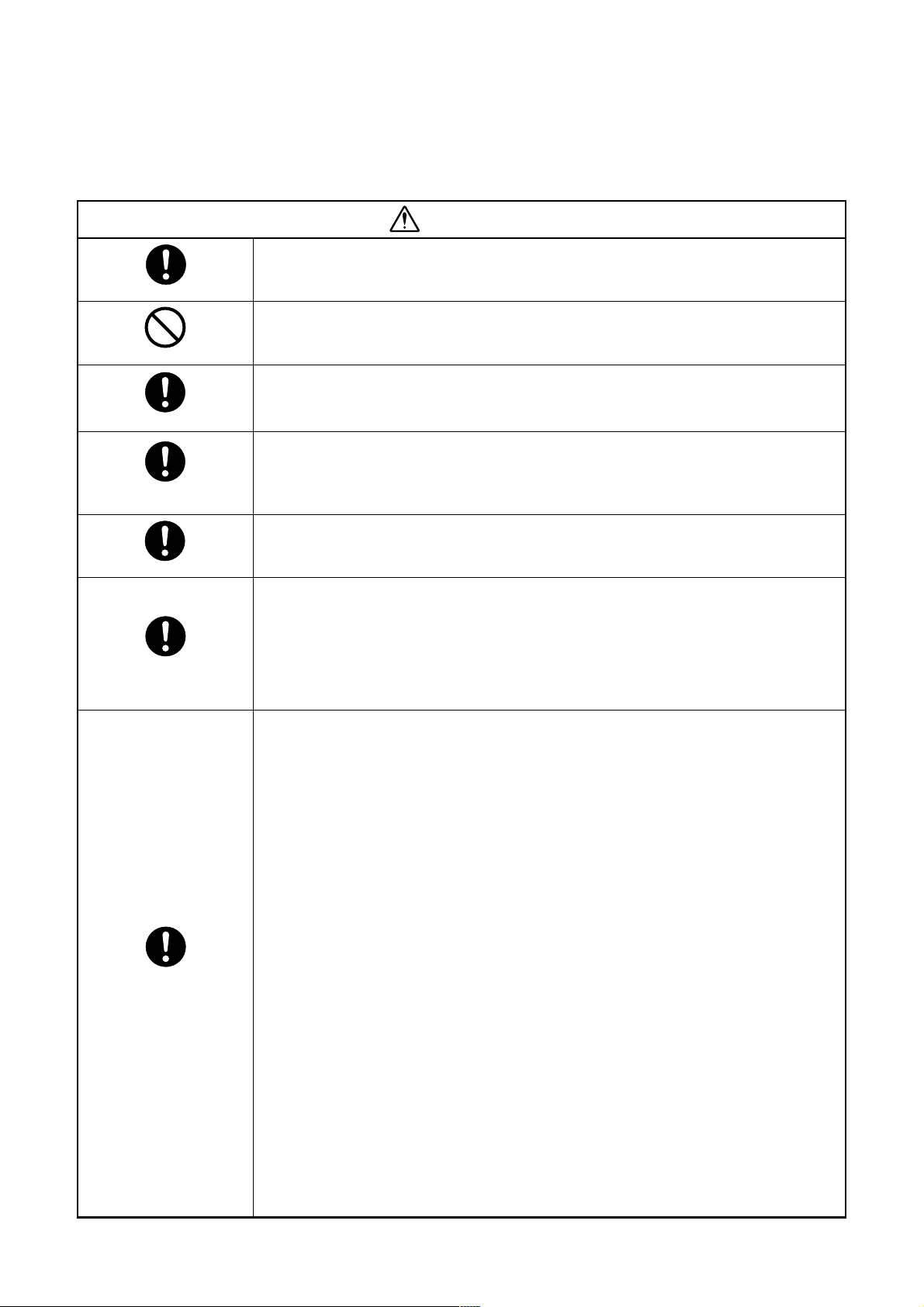
WARNING
Before troubleshooting or repair work, check the earth wire is connected to the earth
terminals of the main unit, otherwise an electric shock is caused when a leak occurs.
Check earth wires.
Prohibition of modification.
Use specified parts.
Do not bring a child
close to the equipment.
Insulating measures
No fire
If the earth wire is not correctly connected, contact an electric engineer for rework.
Do not modify the products.
Do not also disassemble or modify the parts. It may cause a fire, electric shock or injury.
For spare parts, use those specified (
If unspecified parts are used, a fire or electric shock may be caused.
∗: For details, refer to the parts list.
Before troubleshooting or repair work, do not bring a third party (a child, etc.) except
the repair engineers close to the equipment.
It causes an injury with tools or disassembled parts.
Please inform the users so that the third party (a child, etc.) does not approach the equipment.
Connect the cut-off lead cables with crimp contact, etc, put the closed end side
upward and then apply a water-cut method, otherwise a leak or production of fire is
caused at the users’ side.
When repairing the refrigerating cycle, take the following measures.
1) Be attentive to fire around the cycle. When using a gas stove, etc, be sure to put out fire
before work; otherwise the oil mixed with refrigerant gas may catch fire.
2) Do not use a welder in the closed room. When using it without ventilation, carbon
monoxide poisoning may be caused.
3) Do not bring inflammables close to the refrigerant cycle, otherwise fire of the welder may
catch the inflammables.
∗∗
∗).
∗∗
Refrigerant
Check the used refrigerant name and use tools and materials of the parts which
match with it.
For the products which use R410A refrigerant, the refrigerant name is indicated at a
position on the outdoor unit where is easy to see. To prevent miss-charging, the route of the
service port is changed from one of the former R22.
For an air conditioner which uses R410A, never use other refrigerant than R410A.
For an air conditioner which uses other refrigerant (R22, etc.), never use R410A.
If different types of refrigerant are mixed, abnormal high pressure generates in the refrigerating cycle and an injury due to breakage may be caused.
Do not charge refrigerant additionally.
If charging refrigerant additionally when refrigerant gas leaks, the refrigerant composition in
the refrigerating cycle changes resulted in change of air conditioner characteristics or
refrigerant over the specified standard amount is charged and an abnormal high pressure is
applied to the inside of the refrigerating cycle resulted in cause of breakage or injury.
Therefore if the refrigerant gas leaks, recover the refrigerant in the air conditioner, execute
vacuuming, and then newly recharge the specified amount of liquid refrigerant. In this time,
never charge the refrigerant over the specified amount.
When recharging the refrigerant in the refrigerating cycle, do not mix the refrig erant
or air other than R410A into the specified refrigerant.
If air or others is mixed with the refrigerant, abnormal high pressure generates in the
refrigerating cycle resulted in cause of injury due to breakage.
After installation work, check the refrigerant gas does not leak.
If the refrigerant gas leaks in the room, poisonous gas generates when gas touches to fire
such as fan heater, stove or cocking stove though the refrigerant gas itself is innocuous.
Never recover the refrigerant into the outdoor unit.
When the equipment is moved or repaired, be sure to recover the refrigerant with recovering device. The refrigerant cannot be recovered in the outdoor unit; otherwise a serious
accident such as breakage or injury is caused.
3
Page 4
Assembly/Cabling
Insulator check
Ventilation
Be attentive to
electric shock
Compulsion
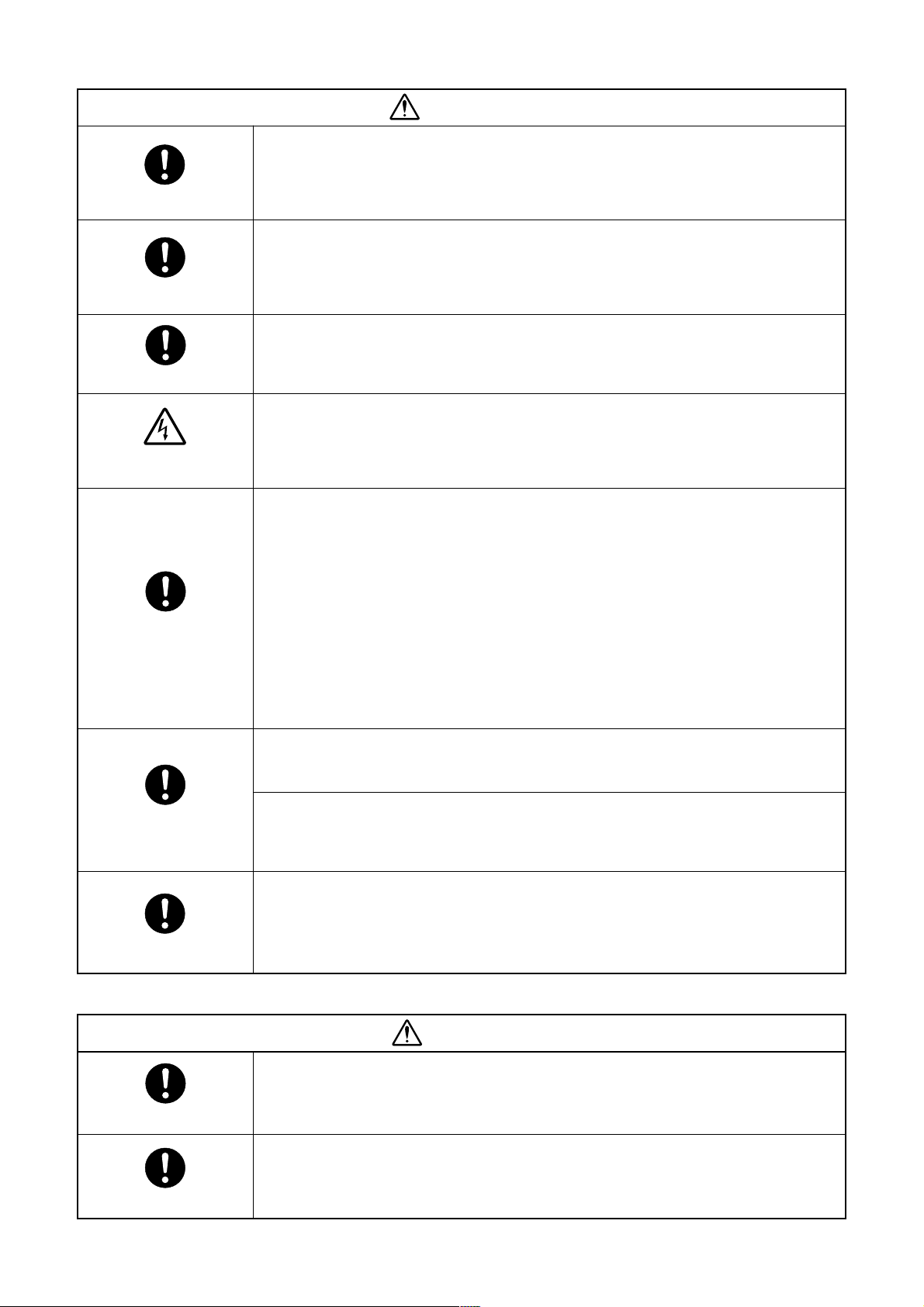
WARNING
After repair work, surely assemble the disassembled parts, and connect and lead the
removed cables as before. Perform the work so that the cabinet or panel does not
catch the inner cables.
If incorrect assembly or incorrect cable connection was done, a disaster such as a leak or
fire is caused at user’s side.
After the work has finished, be sure to use an insulation tester set (500V mugger) to
check the resistance is 2MW or more between the charge section and the non-charg e
metal section (Earth position).
If the resistance value is low, a disaster such as a leak or electric shock is caused at user’s
side.
When the refrigerant gas leaks during work, execute ventilation.
If the refrigerant gas touches to a fire, poisonous gas generates. A case of leakage of the
refrigerant and the closed room full with gas is dangerous because a shortage of oxygen
occurs. Be sure to execute ventilation.
When checking the circuit inevitably under condition of the power-ON, use rubber
gloves and others not to touch to the charging section.
If touching to the charging section, an electric shock may be caused.
When the refrigerant gas leaks, find up the leaked position and repair it surely.
If the leaked position cannot be found up and the repair work is interrupted, pump-down
and tighten the service valve, otherwise the refrigerant gas may leak into the room.
The poisonous gas generates when gas touches to fire such as fan heater, stove or cocking
stove though the refrigerant gas itself is innocuous.
When installing equipment which includes a large amount of charged refrigerant such
as a multi air conditioner in a sub-room, it is necessary that the density does not the
limit even if the refrigerant leaks.
If the refrigerant leaks and exceeds the limit density, an accident of shortage of oxygen is
caused.
For the installation/moving/reinstallation work, follow to the Installation Manual.
If an incorrect installation is done, a trouble of the refrigerating cycle, water leak, electric
shock or fire is caused.
Check after rerair
Check after reinstallation
Put on gloves
Cooling check
After repair work has finished, check there is no trouble.
If check is not executed, a fire, electric shock or injury may be caused. For a check, turn off
the power breaker.
After repair work (installation of front panel and cabinet) has finished, execute a test
run to check there is no generation of smoke or abnormal sound.
If check is not executed, a fire or an electric shock is caused. Before test run, install the
front panel and cabinet.
Check the following items after reinstallation.
1) The earth wire is correctly connected.
2) The power cord is not caught in the product.
3) There is no inclination or unsteadiness and the installation is stable.
If check is not executed, a fire, an electric shock or an injury is caused.
CAUTION
Be sure to put on gloves (
If not putting on gloves, an injury may be caused with the parts, etc.
(∗) Heavy gloves such as work gloves
When the power was turned on, start to work after the equipment has been
sufficiently cooled.
As temperature of the compressor pipes and others became high due to cooling/heating
operation, a burn may be caused.
∗∗
∗) during repair work.
∗∗
4
Page 5

• New Refrigerant (R410A)
This air conditioner adopts a new HFC type refrigerant (R410A) which does not deplete the ozone layer.
1. Safety Caution Concerned to New Refrigerant
The pressure of R410A is high 1.6 times of that of the former refrigerant (R22). Accompanied with change of
refrigerant, the refrigerating oil has been also changed. Therefore, be sure that water, dust, the former refrigerant or the former refrigerating oil is not mixed into the refrigerating cycle of the air conditioner with new refrigerant during installation work or service work. If an incorrect work or incorrect service is performed, there is a
possibility to cause a serious accident. Use the tools and materials exclusive to R410A to purpose a safe work.
2. Cautions on Installation/Service
(1) Do not mix the other refrigerant or refrigerating oil.
For the tools e xclusive to R410A, shapes of all the joints including the service port differ from those of the
former refrigerant in order to prev ent mixture of them.
(2) As the use pressure of the new refrigerant is high, use material thickness of the pipe and tools which are
specified for R410A.
(3) In the installation time, use clean pipe materials and work with great attention so that water and others do
not mix in because pipes are affected by impurities such as water, oxide scales, oil, etc. Use the clean
pipes.
Be sure to brazing with flowing nitrogen gas. (Never use gas other than nitrogen gas.)
(4) For the earth protection, use a vacuum pump for air purge.
(5) R410A refrigerant is azeotropic mixture type refrigerant. Therefore use liquid type to charge the refrigerant.
(If using gas for charging, composition of the refrigerant changes and then characteristics of the air condi-
tioner change.)
3. Pipe Materials
For the refrigerant pipes, copper pipe and joints are mainly used. It is necessary to select the most appropriate
pipes to conform to the standard. Use clean material in which impurities adhere inside of pipe or joint to a
minimum.
(1) Copper pipe
<Piping>
The pipe thickness, flare finishing size , flare nut and others differ according to a refrigerant type.
When using a long copper pipe for R410A, it is recommended to select “Copper or copper-base pipe without
seam” and one with bonded oil amount 40mg/10m or less . Also do not use crushed, deformed, discolored
(especially inside) pipes. (Impurities cause clogging of expansion valves and capillary tubes.)
<Flare nut>
Use the flare nuts which are attached to the air conditioner unit.
(2) Joint
The flare joint and socket joint are used for joints of the copper pipe.
The joints are rarely used for installation of the air conditioner. However clear impurities when using them.
5
Page 6
4. Tools
(1) Required Tools for R410A
Mixing of different types of oil may cause a trouble such as generation of sludge, clogging of capillary , etc.
Accordingly, the tools to be used are classified into the following three types.
1) Tools exclusive for R410A (Those which cannot be used for conventional refrigerant (R22))
2) Tools exclusive for R410A, but can be also used for conventional refrigerant (R22)
3) Tools commonly used for R410A and for conventional refrigerant (R22)
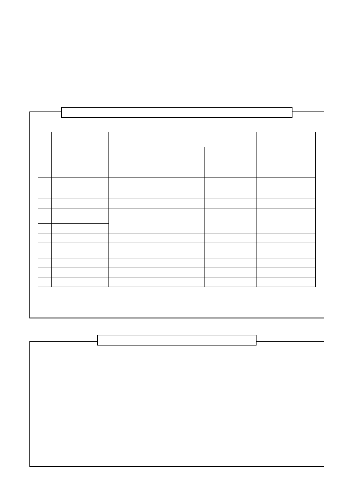
The table below shows the tools exclusive for R410A and their interchangeability.
Tools exclusive for R410A (The following tools for R410A are required.)
Tools whose specifications are changed for R410A and their interchangeability
Conventional air
conditioner installation
Whether new equipment
can be used with
conventional refrigerant
Yes
*(Note 1)
No
No
Yes
Yes
No
Yes
No
No.
Q
R
S
T
U
V
W
X
Y
Y
Used tool
Flare tool
Copper pipe gauge for
adjusting projection
margin
Torque wrench
Gauge manifold
Charge hose
Vacuum pump adapter
Electronic balance for
refrigerant charging
Refrigerant cylinder
Leakage detector
Charging cylinder
Usage
Pipe flaring
Flaring by conventional
flare tool
Connection of flare nut
Evacuating, refrigerant
charge, run check, etc.
Vacuum evacuating
Refrigerant charge
Refrigerant charge
Gas leakage check
Refrigerant charge
air conditioner installation
Existence of
new equipment
for R410A
Yes
Yes
Yes
Yes
Yes
Yes
Yes
Yes
(Note 2)
R410A
Whether conventional equipment can
be used
*(Note 1)
*(Note 1)
No
No
No
Yes
No
No
No
(Note 1) When flaring is carried out for R410A using the conventional flare tools, adjustment of projection
margin is necessary. For this adjustment, a copper pipe gauge, etc. are necessary.
(Note 2) Charging cylinder for R410A is being currently dev eloped.
General tools (Conventional tools can be used.)
In addition to the above exclusive tools, the following equipments which serve also f or R22 are necessary
as the general tools.
(1) Vacuum pump
Use vacuum pump by
attaching vacuum pump adapter.
(2) Torque wrench
(3) Pipe cutter
(4) Reamer
(7) Screwdriver (+, –)
(8) Spanner or Monkey wrench
(9) Hole core drill
(10) Hexagon wrench (Opposite side 4mm)
(11) Tape measure
(12) Metal saw
(5) Pipe bender
(6) Lev el vial
Also prepare the following equipments for other installation method and run check.
(1) Clamp meter
(2) Thermometer
(3) Insulation resistance tester
(4) Electroscope
6
Page 7
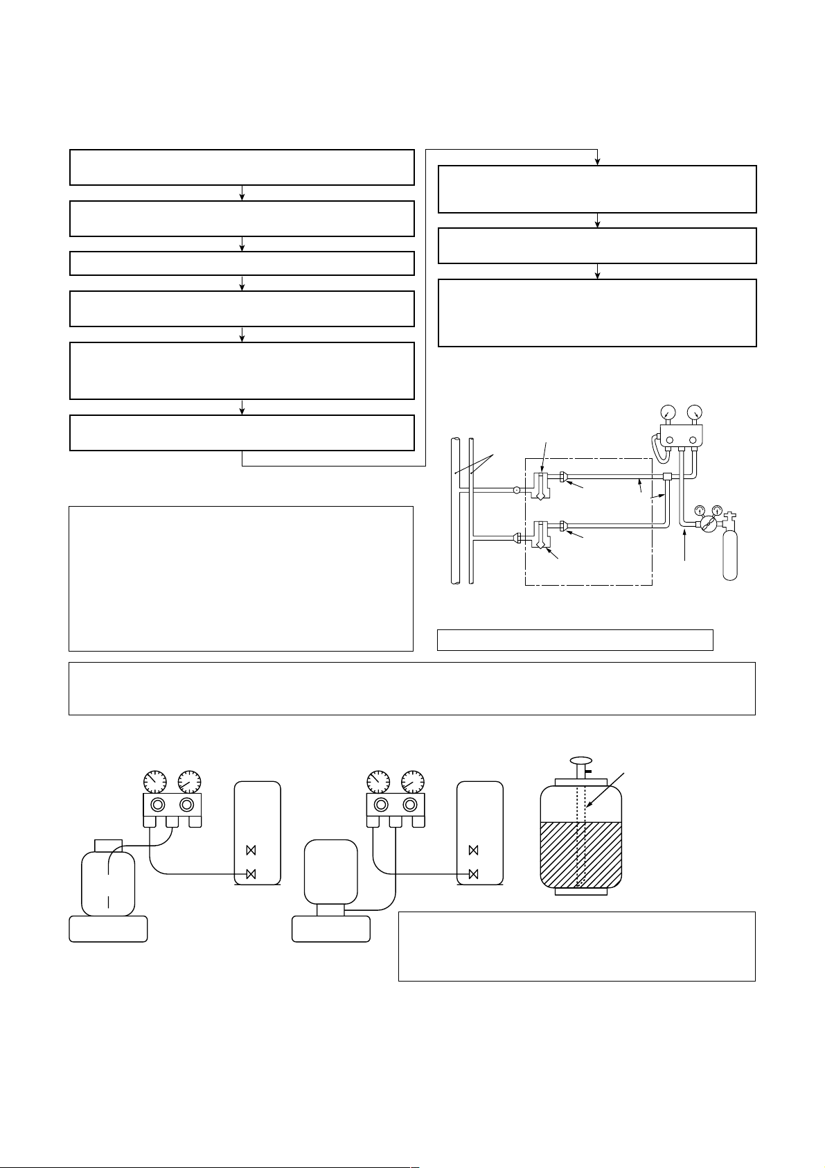
5. Recharge of Refrigerant
When recharge of the refrigerant is required, charge the new refrigerant with the specified amount in the
procedure as described below .
Recover the refrigerant and check there is no refrigerant in the
equipment.
Connect the charge hose to the packed valve service ports at gas
side, liquid side, and balance side of the outdoor unit.
Connect the charge hose to vacuum pump adaptor.
Open the packed valves of the balance pipe fully at liquid and gas
sides, and then return the valve at gas side a little to the closed side.
Open fully PMV of the outdoor unit.
• Turn on power of the outdoor unit.
• Short CN30 on I/F P.C. board of the outdoor unit.
•
Turn off power of the outdoor unit within 2 minutes after short-circuiting.
When the pressure has lowered until indication of the
compound gauge pointed -0.1MPa (–76cmHg), open fully the
handle Low and turn off the power of vacuum pump.
Leave it as it is for 1 to 2 minutes and check the indicator of
the compound gauge does not return.
Set the refrigerant cylinder on the electron balance, connect
the charge hose to connecting ports of the cylinder and the
electron gauge, and then charge the liquid refrigerant from the
service port at liquid side. (Shield with the gauge manifold so
that refrigerant does not flow to gas side.)
(Charge the refrigerant as below.)
Low-
pressure gauge
pressure gauge
High-
Open fully the handle Low of the gauge manifold, and then turn on
the power of vacuum pump for vacuuming.
Never charge the refrigerant o ver the specified amount.
Q
Do not charge the additional refrigerant.
R
Connected to
indoor unit
Main
pipe
Brazed
Fully
tightened
Valve fully closed
(gas side)
If charging refrigerant additionally when refrigerant gas
leaks, the refrigerant composition in the refrigerating
cycle changes resulted in change of air conditioner
characteristics or refrigerant over the specified standard amount is charged and an abnormal high
Connected to other
terminal units
Valve fully closed
(liquid side)
pressure is applied to the inside of the refrigerating
cycle resulted in cause of breakage or injury.
Set the equipment so that liquid refrigerant can be charged.
Q
When using a cylinder with siphon pipe, liquid can be charged without inversing the cylinder.
R
4mm-hexagonal wrench is required.
[ Cylinder with siphon ] [ Cylinder without siphon ]
Gauge manifold
OUTDOOR unit
Gauge manifold
OUTDOOR unit
Center unit
Service
port
Copper pipe
Service port
Ø6.4
Siphon
VLV
H
Reducing
valve
Ø6.4
Copper pipe
Gauge
manifold
Nitrogen
gas
cylinder
Refrigerant
cylinder
Electronic
balance
Electronic
balance
Refrigerant
R410A refrigerant is consisted with HFC mixed refrigerant.
Therefore if the refrigerant gas is charged, the composition
of the charged refrigerant changes and characteristics of
the equipment changes.
6. Environment
Use “Vacuum pump method” for an air purge (Discharge of air in the connecting pipe) in installation time.
• Do not discharge flon gas into the air to protect the earth environment.
• Using the vacuum pump method, clear the remained air (Nitrogen, etc.) in the unit. If the air remains, the
pressure in the refrigerating cycle becomes abnormally high and an injury and others are caused due to burst.
7
Page 8
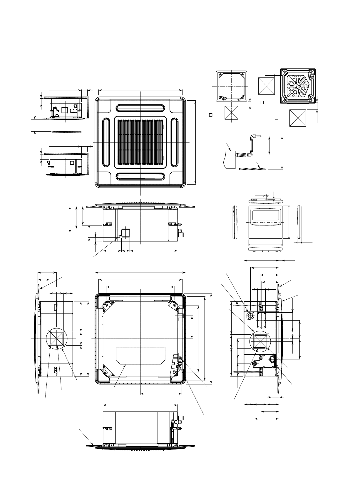
1. CONSTRUCTION VIEWS (EXTERNAL VIEWS)
200
1000 or more
15 or more
1000 or more
Obustacle
1000 or more
15 or more
Space required for
installation and servicing
149
175
207
64
Knockout for fresh
145.5
93
105
air intake Ø100
Bottom face
of ceiling
70
595 to 660 Ceiling open dimension
142 64 368.5
29
700 Panel external dimension
595 to 660 Ceiling open dimension
525 Hanging bolt pitch
Check port
( 450)
Check port
(o 450)
200
Check port
( 450)
Drain-up standing-up size
Indoor unit
627.5
or less
Stand-up
Bottom face
of ceiling
Stand-up
850 or less
Note)
595 to 660 Ceiling open dimension
As ABS is used for the drain discharge port of the main unit,
the vinyl chloride paste cannot be used.
Use the flexible hose (Band fix) included in the package.
4
2.7
• Wired remote
controller
120
(RBC-AMT31E)
120
268 27
220.5
Drain discharge port
Hanging bolt
M10 or W3/8
local arrange
145.5
134
63
Bottom face
of ceiling
Ceiling panel
200
16
Ø162 (Pitch)
For branch duct
knockout square hole Ø150
4-Ø3.2 hole
(For 4mm tapping screw)
Bottom face of ceiling
105235 235
575 Unit external dimension
Electric parts box
320.5
575 Unit external dimension
Ø162
(Pitch)
256
177
525 Hanging bolt pitch
700 Panel external dimension
595 to 660 Ceiling open dimension
Refrigerant pipe
(Liquid) Ø6.4
For branch ductt
knockout square
hole Ø150
Refrigerant pipe (Gas)
0151, 0181MH : Ø12.7
0071 to 0121MH : Ø9.5
214 105
97.5 42 148
139.5
190.5
120
21
4-Ø3.2 hole
(For 4mm
tapping screw)
Wiring connection
port
55
9310570
142
158
8
Page 9
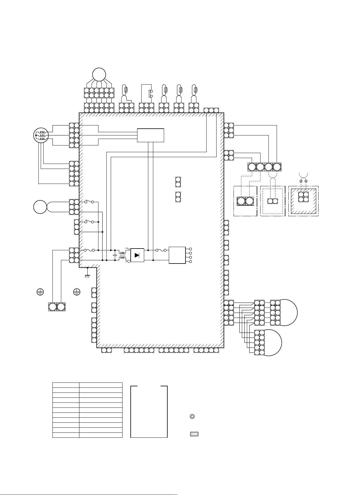
2. WIRING DIAGRAM
PMV
DP
Indoor unit
earth screw
Power supply
single phase
220-240V, 50Hz
220V, 60Hz
CN333
(WHI)
5
3
1
CN334
(WHI)
5
4
1
CN68
(BLU)
1 1
3 3
CN304
(GRY)
CN67
(BLK)
RED
1 1
WHI
3 3
Flow selector
unit earth screw
S(N)R(L)
6 4 3 1 2 5
6 4 3 1 2 5
1 2 3 4 5 6
1 2 3 4 5 6
CN82 (BLU)
5
3
1
5
4
3
2
1
RY302
1
RY303
3
Fuse
T6.3A
250V
P301
BLK
TC1
1 3
1 2 3
CN100
(BRW)
~
1
CN66
(WHI)
2
1
CN44
(BRW)
2
1
2
CN50
(WHI)
3
4
CN32
5
(WHI)
21
T10
(Fan drive) Option
Control P.C. board
CN61
(YEL)
FS
1 3
1 2 3
CN34
(RED)
drive circuit
1 2 1 2 1 2
CN104
(YEL)
Motor
CN71
CN72
Fuse
T3.15A
250V
~
for Indoor unit
MCC-1402
TA TCJ TC2
CN101
CN102
(BLK)
(RED)
1
(CHK)
2
1
(DISP)
2
654321 54321654321
DC20V
DC15V
DC12V
DC 7 V
CN81
(BLK)
Power
supply
circuit
CN60
(WHI)
CN309
(YEL)
3 11 2 1 2 1 2
CN80
(GRN)
CN73
(RED)
CN70
(WHI)
CN20
(BLU)
CN33
(WHI)
CN41
(BLU)
3
3
2
1
1
CN40
(BLU)
2
5
2
1
5
1
3
2
PNL
1
2
EXCT
1
2
Filter
1
5
4
3
GRL
2
1
1
1
2
2
3
3
4
4
5
5
BLK
BLK
BLU
BLU
Outdoor
unit
U2U1
remote controller
1
1
2
2
3
3
4
4
5
5
1
1
2
2
3
3
4
4
5
5
Wireed
1
2
3
4
5
LM2
BAU2U1
remote controller
1
2
3
LM1
4
5
WHI BLK
1 2
1 2
CN001
(WHI)
Adapter for
wireless
Symbol
FM
TA
TC1
TCJ
TC2
LM1, LM2
DP
FS
RY302
PMV
Parts name
Fan motor
Indoor temp. sensor
Temp. sensor
Temp. sensor
Temp. sensor
Louver motor
Drain pump motor
Float switch
Drain control relay
Pulse motor valve
Color
indication
RED : RED
WHI : WHITE
YEL : YELLOW
BLU : BLUE
BLK : BLACK
GRY : GRAY
PNK : PINK
ORN: ORANGE
BRW: BROWN
GRN: GREEN
1. indicates the terminal bolock letter.
Letter at inside indicates the terminal number.
2. A dotted line and broken line indicate the wiring at site
3. indicates a control P.C. board.
9
Page 10
3. PARTS RATING
3-1. Parts Rating
Model MMU-
Fan motor
Motor for horizontal grille
Pulse motor
Pulse motor valve
TA sensor
TC1 sensor
TC2 sensor
TCJ sensor
Float switch
Drain pump motor
AP0071MH AP0091MH AP0121MH AP0151MH AP0181MH
SWF-230-60-1R
MP24Z3N
EDM-MD12TF-3
EDM-B25YGTF-3 EDM-B40YGTF-3
Lead wire length : 155mm Vinyl tube
Ø4 size lead wire length : 1400mm Vinyl tube
Ø6 size lead wire length : 1500mm Vinyl tube (Black)
Ø6 size lead wire length : 1400mm Vinyl tube (Red)
FS-0218-103
ADP-1409
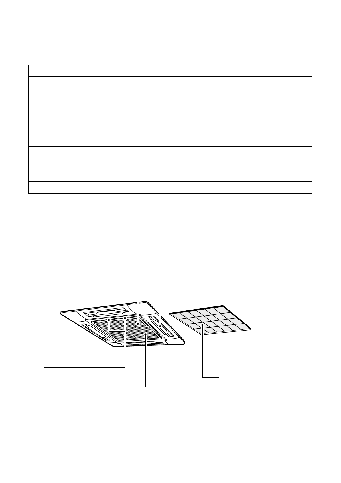
3-2. Name of Each P art
Earth screw
It is included in the electric parts box.
Clip
The clip is to open/close the air inlet grille.
Air inlet grille
Air in the room is sucked from here.
Air outlet/Air outlet flap
Select air blow direction in cooling or
heating operation each.
Air filter
Removes dust and trash.
(Air filter is provided in the air grille.)
10
Page 11
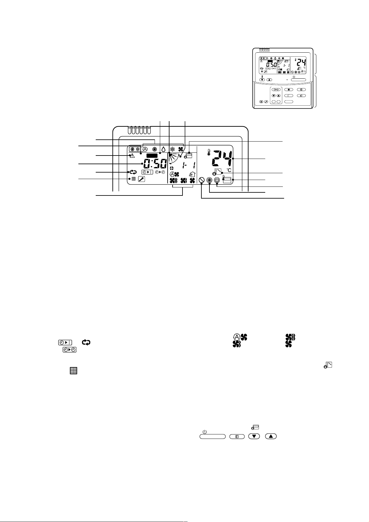
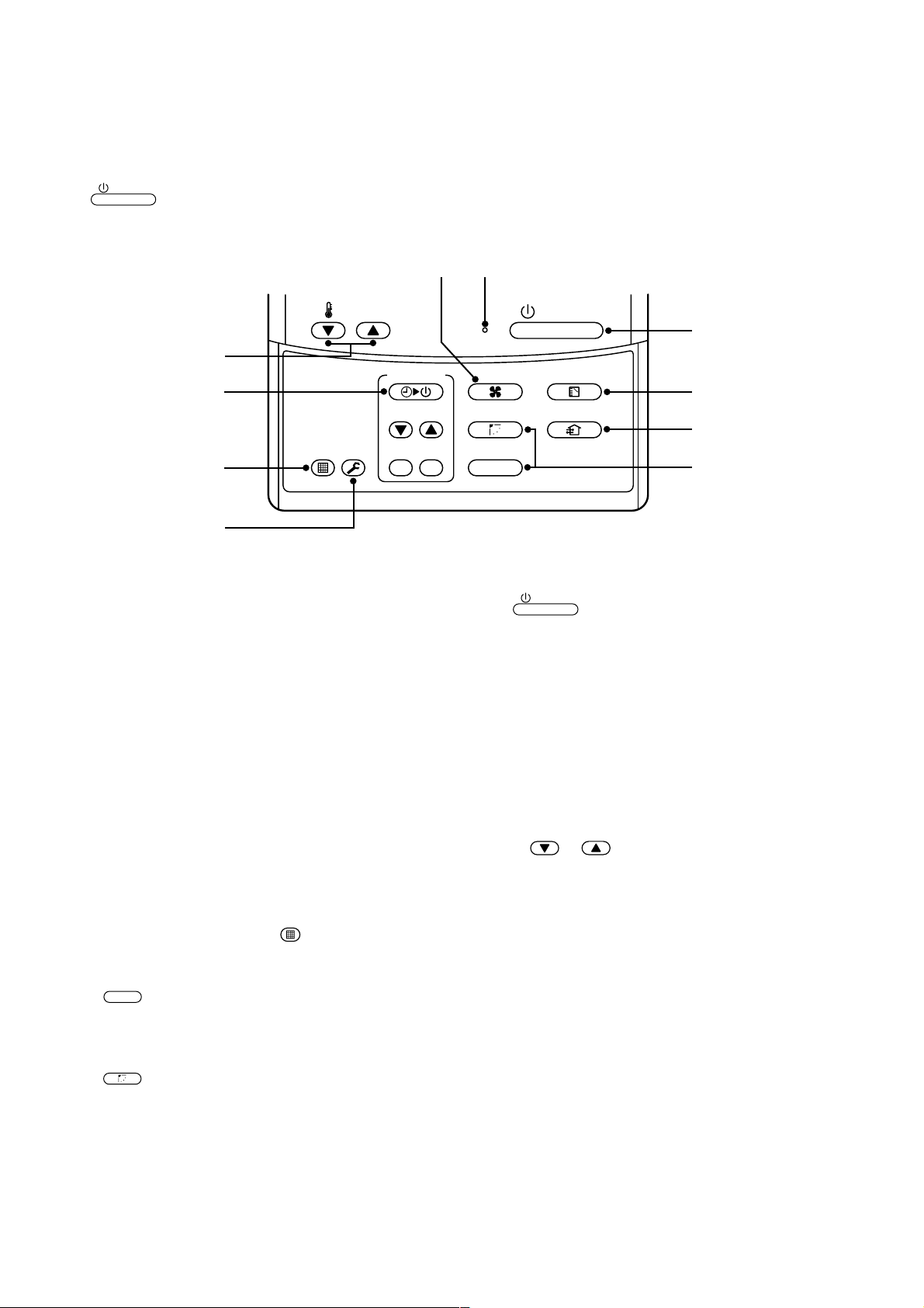
3-3. Parts Name of Remote Controller
Display section
In the display example, all indicators are displayed for the explanation.
In reality only, the selected contents are indicated.
• When turning on the leak breaker at the first time, [SET DATA] flashes on the
display part of the remote controller. While this display is flashing, the model is
being automatically confirmed. Accordingly, wait for a while after [SET DATA]
display has disappeared, and then use the remote controller.
78 9
2
1
4
3
5
SET
H
DATA
SETTING
TEST
UNIT No.
R.C. No.
CODE No.
6
15
1
SET DATA display
Displayed during setup of the timer.
2
Operation mode select display
The selected operation mode is displayed.
3
CHECK display
Displayed while the protective device works or a
trouble occurs.
12
PRE-HEAT display
Displayed when the heating operation starts.
While this indication is displayed, the indoor fan
stops.
13
Operation ready display
Displayed when cooling or heating operation is
impossible because the outdoor temperature goes
out of the operable range.
FILTER
RESET
SET
H
TEMP .
DATA
SETTING
TEST
10
11
12
TEST
TIMER SET
UNIT No.
R.C. No.
SWING/FIXTIME
17
16
13
14
CODE No.
ON / OFF
FAN
MODE
VENT
UNITSET CL
Display
section
Operation
section
4
Timer time display
Time of the timer is displayed. (When a trouble
occurs, the check code is displayed.)
5
Timer SETIN setup display
When pushing the Timer SET button, the display
of the timer is selected in order of
[OFF]
→ [ON]
6
Filter display
If “FILTER ” is displayed, clean the air filter.
7
TEST run display
Displayed during a test run.
8
Flap position display
Displays flap position.
9
SWING display
Displayed during up/down movement of the flap.
10
Set up temperature display
The selected set up temp. is displayed.
11
Remote controller sensor display
Displayed while the sensor of the remote
controller is used.
→ [OFF] repeat OFF timer
→ No display.
14
No function display
Displayed if there is no function even if the button is
pushed.
15
Air volume select display
The selected air volume mode is displayed.
(AUTO)
(MED.) (LOW)
16
Mode select control display
Displayed when pushing “Operation mode select ”
button while the operation mode is fixed to heating
or cooling by the system manager of the air conditioner.
17
Central control display
Displayed when using the remote controller together
with the central control remote controller, etc.
If Remote controller is prohibited at the
centralcontrol side,
ON / OFF
the change is not accepted.
(The contents available to be set up on the remote
controller differ according to the central control
mode. For details, refer to Owner’s Manual of the
central control remote controller.)
MODE
,
(HIGH)
flashes when operating
, / buttons and
11
Page 12
Operation section
ON / OFF
Push each button to select a desired operation.
This remote controller can operate the maximum 8 indoor units.
• The details of the operation needs to be set up once, afterward, the air conditioner can be used by pushing
ON / OFF
button only.
1
7
TEMP.
10
2
FIL TER
TEST
RESET
5
3
1
Air volume select button
Selects the desired air volume mode.
2
Timer set button
TIMER SET button is used when the timer is set
up.
3
Check button
The CHECK button is used for the check operation. During normal operation, do not use this
button.
4
Fan button
FAN button is used when a fan which is sold on
the market or etc. is connected.
TIMER SET
ON / OFF
8
FAN
SWING/FIXTIME
MODE
VENT
9
4
UNITSET CL
6
8
When the button is pushed, the operation starts,
and it stops by pushing the button again.
When the operation has stopped, the operation
lamp and all the displays disappear.
9
Operation select button
Selects desired operation mode.
10
Set up temperature button
Adjusts the room temperature.
Set the desired set temperature by pushing
button
or .
5
Filter reset button
Resets (Erases) “FILTER ” display.
6
Wind direction and Swing
UNIT
:
If the multiple indoor units are operated by only
one remote controller, select the units when the
air direction is adjusted.
SWING/FIX
:
Set up the auto swing and angle of the flap.
7
Operation lamp
Lamp is lit during the operation. Lamp is off when
stopped.
Although it flashes when operating the protection
device or abnormal time.
OPTION :
Remote controller sensor
Usually the TEMP. sensor of the indoor unit senses
the temperature. The temperature on the surrounding of the remote controller can also be sensed.
For details, contact the dealer from which you have
purchased the air conditioner.
• In case that one remote controller controls the
multiple indoor units, the setup operation is
unavailable in group control.
12
Page 13
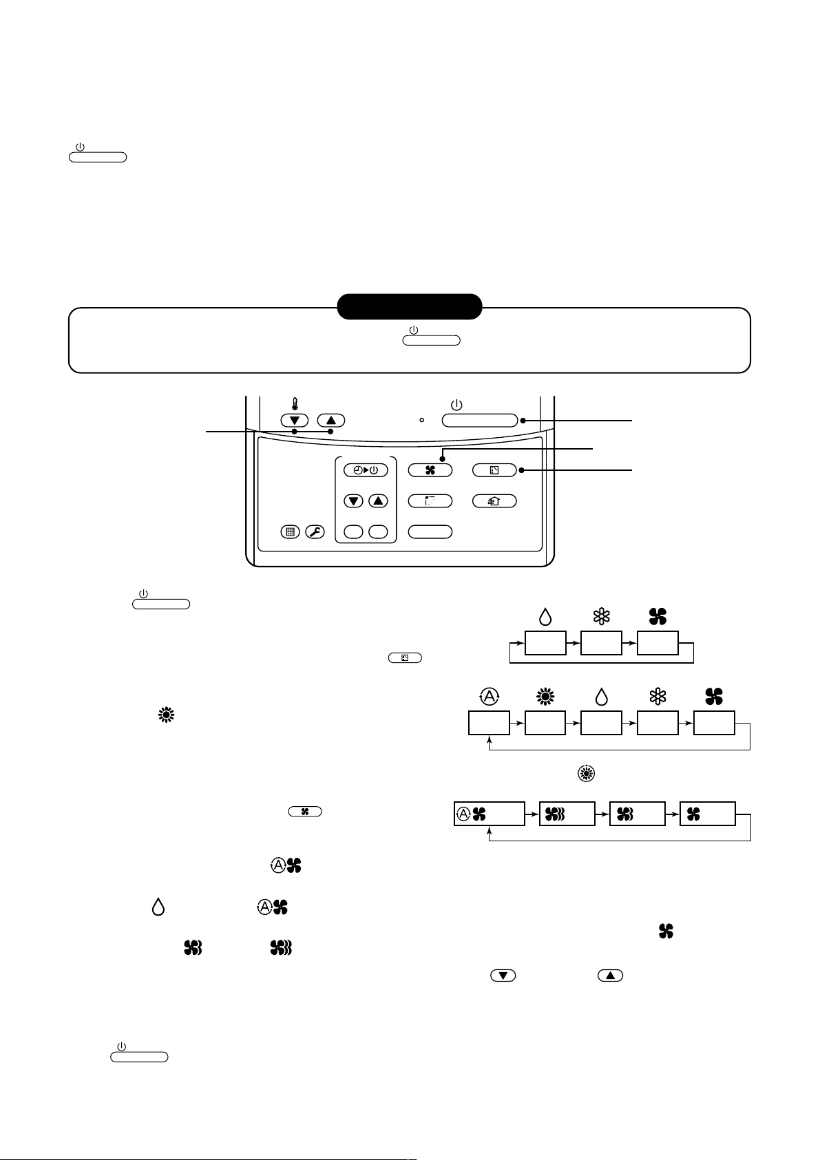
3-4. Correct Usage
LOW MED. HIGH
AUTO
When you use the air conditioner for the first time or when you change the SET DATA value, follow the procedure below. From the next time, the operation displayed on the remote controller will start by pushing the
ON / OFF
Preparation
Turn on the main power switch and/or the leakage breaker.
• When the power supply is turned on, a partition line is display ed on the display part of the remote controller.
* After the power supply is turned on, the remote controller does not accept an operation for approx. 1 minute,
but it is not a f ailure.
• While using the air conditioner, operate it only with
button only.
switch and the leak breaker.
REQUIREMENT
ON / OFF
button without turning off the main power
TEMP.
ON / OFF
1
4
3
2
(Dehumidity)
SWING/FIXTIME
MODE
FAN
UNITSET CL
” button.
TIMER SET
FIL TER
TEST
RESET
1
Push
The operation lamp goes on, and the operation starts.
2
Select an operation mode with the “MODE
One push of the button, and the display
changes in the order shown on the right.
• In HEAT mode, if the room temperature reaches to
the set temperature, the outdoor unit stops and the air
flow becomes ULTRA LOW and the air volume decreases.
• In the heating mode, the fan stops so that cool air is not discharged and Heat is displayed.
3
Select air volume with “FAN
One push of the button, and the display
changes in the order shown on the right.
• When air volume is “AUTO ”, air volume differs according to the temperature difference between set
temp. and room temp.
ON / OFF
button.
FAN
” button.
MODE
VENT
AUTO
Cooling only model
DRY COOL FAN
Heat-pump model
HEAT DRY COOL FAN
• In DRY mode, “AUTO ” is displayed and the air volume is LOW.
• In heating operation, if the room temperature is not heated sufficiently with VOLUME “LOW ” operation,
select “MED. ” or “HIGH ” operation.
4
Determine the set up temperature by pushing the “TEMP. ” or “TEMP. ” button.
Stop
Push
The operation lamp goes off, and the operation stops.
ON / OFF
button.
13
Page 14
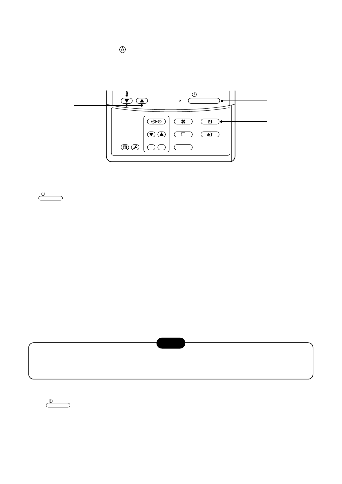
3-5. Automatic Operation (Super Heat Recovery Type Only)
When you set the air conditioner in mode or switch over from AUTO operation because of some settings
change, it will automatically select either cooling, heating, or fan only operation depending on the indoor temperature.
TEMP.
ON / OFF
1
3
FAN
SWING/FIXTIME
UNITSET CL
FIL TER
RESET
TIMER SET
TEST
Start
ON / OFF
1
Push this button to start the air conditioner.
2
Mode select button (MODE)
Select Auto.
3
Temperature button
Set the desired temperature.
• In case of cooling, start the operation after approx. 1 minute.
• In case of heating, the operation mode is selected in accordance with the room temperature and operation
starts after approximately 3 to 5 minutes.
• When you select the Auto mode, it is unnecessary to set the fan speed.
The FAN speed display will show A UTO and the fan speed will be automatically controlled.
• After the heating operation has stopped, FAN operation may continue for approx. 30 seconds.
• When the room temperature reaches the set temperature and the outdoor unit stops, the super low wind is
discharged and the air volume decreases e xcessively.
During defrost operation, the fan stops so that cool air is not discharged and “HEAT READ Y” is displayed.
• If the Auto mode is uncomfortable, you can select the desired conditions manually.
button
MODE
VENT
2
NOTE
When restarting the operation after stop
• When restarting the operation immediately after stop, the air conditioner does not oper ate for approx. 3
minutes to protect the machine.
Stop
Push
Push this button again to stop the air conditioner.
ON / OFF
button.
14
Page 15
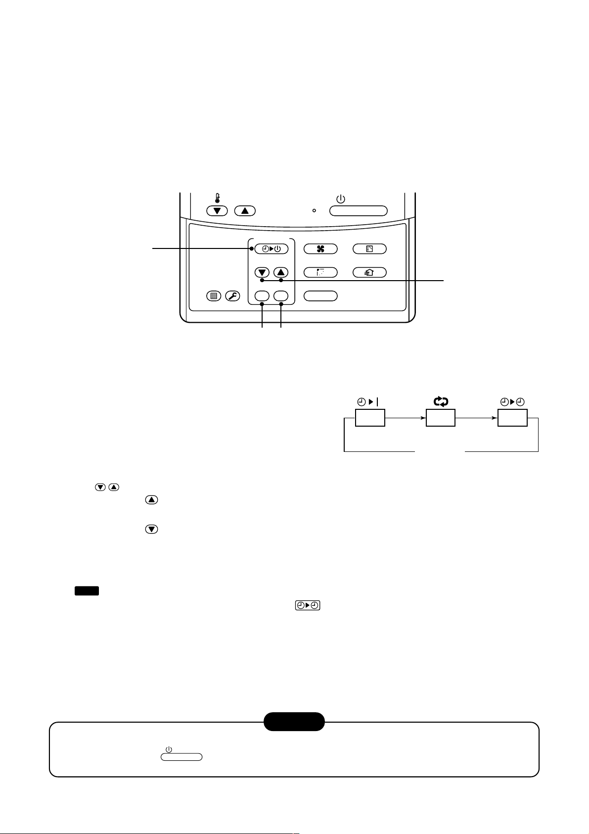
3-6. TIMER Operation
OFF
(OFF timer) (Repeat OFF timer)
No display
(ON timer)
OFF ON
A type of timer operation can be selected from the following three types.
OFF timer : The operation stops when the time of timer has reached the set time.
Repeat OFF timer : Every time, the operation stops after the set time has passed.
ON timer : The operation starts when the time of timer has reached the set time.
Timer operation
TEMP.
TIMER SET
FAN
ON / OFF
MODE
1
SWING/FIXTIME
FIL TER
TEST
RESET
3
4
1
Push TIMER SET button.
• The timer display (type) changes for every
push of the button.
• SET DATA and timer time displays flash.
2
Push
For e very push of button, the set time increases in the unit of 0.5 hr (30 minutes).
The maximum set time is 72.0 hr.
For e very push of button, the set time decreases in the unit of 0.5 hr (30 minutes).
The minimum set time is 0.5 hr.
TIME
to select “SET TIME”.
UNITSET CL
VENT
2
3
Push SET button.
SETTING
•
display disappears and timer time display goes on.
(When ON timer is activated, timer time, ON timer are displayed and other displays disappear.)
Cancel of timer operation
4
Push CL button.
• TIMER display disappears.
• When the operation stops after the timer reached the preset time, the Repeat OFF timer resumes the
operation by pushing
set time.
ON / OFF
NOTICE
button and stops the operation after the time of the timer has reached the
15
Page 16
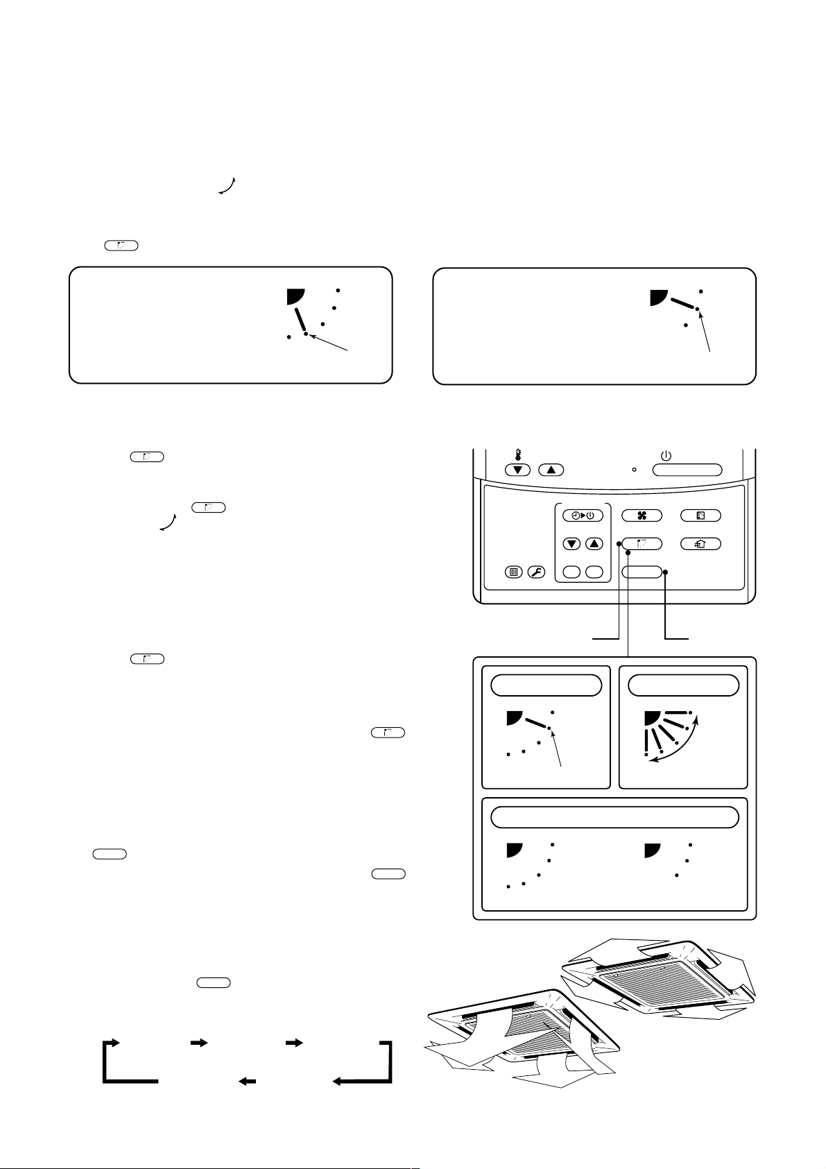
3-7. Adjustment of Wind Direction
• While the air conditioner stops, the horizontal flap (Up/Down air direction adjustment plate) automatically directs upward.
• While the air conditioner is in ready status for heating, the horizontal flap (Up/Down air direction
adjustment plate) directs upward. The swinging operation starts after heating ready status has been
cleared, but “SWING ” is displayed on the remote controller even if the status is ready to heating.
How to set up the air direction
SWING/FIX
Push
button during operation.
1
Every pushing the button, the air direction changes.
In Heating operation
Set the horizontal flap (Up/Down
air direction adjustment plate)
downward. If directing it upward,
the hot air may not come to the
foot come to the foot.
Initial setup
How to start swinging
2
SWING/FIX
Push
button.
Set direction of the horizontal flap (Up/Down air
direction adjustment plate) to the lowest position
and then push
SWING/FIX
button again.
• [SWING ] is displayed and the air direction
automatically changes upward/downward.
In case when one remote controller controls the
multiple indoor units, each indoor unit can be selected and its air direction can be set up.
How to stop swinging
3
4
SWING/FIX
Push
button again during swinging of the
horizontal flap.
• The horizontal flap can be stopped at the desired
position. After then the air direction can be again set
up from the uppermost position by pushing
button.
* While the horizontal flap is set downward in cool-
ing/drying operation, it does not stop.
If stopping the horizontal flap which directs downward during swinging, it stops after moving to the
3rd position from the top position.
UNIT
• To set up the air direction individually, push
button to display each indoor unit No. in a group
control. Then set up the air direction to a displayed
indoor unit.
• If there is no display, all the indoor units can be
operated collectively.
• Every pushing
UNIT
button, the display exchanges
as shown in the figure.
SWING/FIX
UNIT
In Cooling / Dry operation
Set the horizontal flap (Up/Down
air direction adjustment plate)
upward. If directing it downward,
the dew may fall on near the air
air outlet port or it drips.
TEMP.
TIMER SET
SWING/FIXTIME
FIL TER
TEST
RESET
1, 2, 3 4
In FAN operation
Initial setup
Display when stopping the swing
Fan/Heat
operation
ON / OFF
FAN
UNITSET CL
In all modes
Initial setup
MODE
VENT
Series of
operation
Cool/Dry
operation
Unit No. 1-1No display Unit No. 1-2
Unit No. 1-4 Unit No. 1-3
16
Page 17
3-8. Information
Confirmation before operation
• Turn on the power switch 12 hours before starting
the operation.
• Make sure whether earth wire is connected.
• Make sure the air filter is connected to the indoor
unit.
Heating capacity
• A heat pump system which absorbs heat from
outside of the room and then discharges heat into
the room is adopted for heating. If the outside
temperature falls, the heating capacity decreases.
• When the outside temperature is too low, it is
recommended to use this air conditioner together
with other heating equipment.
Defrost during heating operation
• In heating operation, if there is frost on the outdoor
unit, the operation changes automatically to the
defrost operation (Approx. 2 to 10 minutes) to
increase the heating efficiency.
• During defrost operation, the fan of the indoor unit
stops.
3-minutes protection
Protective device (High pressure s witch)
This device stops automatically an operation when
excessive force is applied on the air conditioner.
If the protective device w o rks, the operation stops
and the operation lamp flashes.
When the protective device works, the indication
and the check code are displayed on the display
section of the remote controller. In the following
cases, the protective device may work.
In cooling operation
• The suction port or discharge port of the outdoor
unit is closed.
• A strong wind continuously blows to the discharge
port of the outdoor unit.
In heating operation
• Dust or waste adheres excessively to air filter of
the indoor unit.
• The discharge port of the indoor unit is closed.
If the protective device w o rks, turn off the main
power switch, solve the cause, and then start the
operation again.
TEST
• When restarting the operation just after the
operation has been stopped or the main power
switch has turned on, the outdoor unit does not
work for approx. 3 minutes in order to protect the
air conditioner.
Power failure
• If a power failure occurred during operation, all
operations stop.
• When the power is returned after a power failure,
the operation lamp notifies the power-ON by
flashing operation lamp on the remote controller.
• When restarting the operation, push
button again.
ON / OFF
Fan rotation in stopped unit
• In heating operation even in the stopped indoor
unit, the fan rotates once for several minutes per
approx. an hour when the other indoor unit is
operating to protect the air conditioner .
Cooling/Heating operation of Super
Modular Multi system air conditioner
• Although each indoor unit can be individually
controlled in the Super Modular Multi system air
conditioner, the cooling oper ation and the heating
operation cannot be simultaneously performed in
the multiple indoor units which are connected to
an outdoor unit.
• If the cooling operation and the heating operation
are simultaneously performed, the indoor unit
which ex ecutes cooling operation stops, and on
the operation section lights up. On the other hand,
the indoor unit which executes heating oper ation
continues running. In a case that the manager of
the air conditioner has fixed the operation to
cooling or heating, an operation other than that set
up is unavailable. If an operation other than that
set up is ex ecuted, on the operation section
lights up and the operation stops.
Characteristics of heating operation
• The wind is not out just after starting an operation.
The hot wind starts to blow 3 to 5 minutes after
(Time differs according to indoor/outdoor temperature.) the indoor heat exchanger has warmed up.
• During operation, the outdoor unit may stop if the
outside temperature rises.
17
Page 18
3-9. Air Conditioner Operations and Performance
3 minutes protection function
3-minutes protection function prevents the air conditioner from starting for initial 3 minutes after the main powe r
switch/circuit breaker is turned on for re-starting the air conditioner.
Power failure
Power failure during operation will stop the unit completely.
• To restart the operation, push the START/STOP button on the remote controller.
• Lightning or a wireless car telephone operating nearby may cause the unit to malfunction. Turn off the main
power switch or circuit breaker and then turn them on again. Push the START/STOP button on the remote
controller to restart.
Heating characteristics
Preheating operation
The air conditioner will not deliver warm air immediately after it is turned on. Warm air will start to flow out after
approximately 5 minutes when the indoor heat e xchanger warmed up.
Warm air control (In heating operation)
When the room temperature reaches the set temperature, the f an speed is automatically reduced to prevent to
blow cold draft. At this time, the outdoor unit will stop.
Defrosting operation
If the outdoor unit is frosted during the heating operation, defrosting starts automatically (for approximately
2 to 10 minutes) to maintain the heating capacity.
• The fans in both indoor and outdoor units will stop during the defrosting operation.
• During the defrosting operation, the defrosted water will be drained from the bottom plate of the outdoor unit.
Heating capacity
In the heating operation, the heat is absorbed from the outside and brought into the room. This way of heating
is called heat pump system. When the outside temperature is too low, it is recommended to use another heating
apparatus in combination with the air conditioner .
Attention to snowfall and freeze on the outdoor unit
• In snowy areas, the air inlet and air outlet of the outdoor unit are often covered with snow or frozen up.
If snow or freeze on the outdoor unit is left as it is, it may cause machine failure or poor warming.
• In cold areas, pay attention to the drain hose so that it perfectly drains w ater without w ater remaining inside for
freeze prevention. If water freezes in the drain hose or inside the outdoor unit, it may cause machine failure or
poor warming.
Air conditioner operating conditions
For proper perf ormance, operate the air conditioner under the following temperature conditions:
Cooling operation
Dry operation
Outdoor temperature : –5°C to 43°C
Room temperature : 21°C to 32°C (Dry valve temp.), 15°C to 24°C (Wet valve temp.)
CAUTION
Outdoor temperature : 15°C to 43°C (Maximum suction air temp. 46°C)
Room temperature : 17°C to 32°C
Room relative humidity – less than 80 %. If the air conditioner operates
in excess of this figure, the surface of the air conditioner may cause dewing.
Heating operation
If air conditioner is used outside of the above conditions, safety protection may work.
Outdoor temperature : –15°C to 15°C (Wet valve temp.)
Room temperature : 15°C to 28°C (Dry valve temp.)
18
Page 19
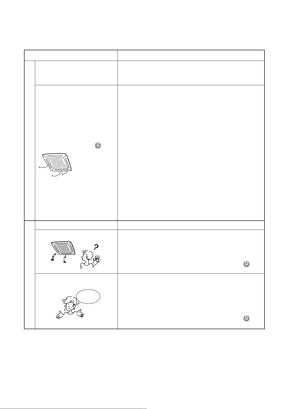
3-10. When the Following Symptoms are Found
Check the points described below before asking repair servicing.
Symptom
Outdoor unit • White misty cold air
or water is out.
• Sometimes, noise
“Pushu !” is heard.
Indoor unit •“Swish” sound is
heard sometimes.
• Slight “Pishi!” sound
is heard.
• Discharge air smells.
• The operation lamp
flashes
•“STANDBY
indication is lit.
Check again.
• Sound or cool air is
output from the
stand by indoor unit.
• When power of the
air conditioner is
turned on, “Ticktock”
sound is heard.
Cause
• Fan of the outdoor unit stops automatically and performs defrost
operation.
• Solenoid valve works when defrost operation starts or finishes.
• When the operation has started, during the operation, or immediately
after the operation has stopped, a sound such as water flows may be
heard, and the operation sound may become larger for 2 or 3 minutes
immediately after the operation has started. They are flowing sound of
refrigerant or draining sound of dehumidifier.
• This is sound generated when heat exchanger, etc. expand and
contract slightly due to change of temperature.
• Various smell such as one of wall, carpet, clothes, cigarette, or
cosmetics adhere to the air conditioner.
• Flashes when power is turned on again after power failure, or when
power switch is turned on.
”
• When cooling operation cannot be performed because another indoor
unit performs heating operation.
• When the manager of the air conditioner has fixed the operation to
COOL or HEAT, and an operation contrary to the setup operation is
performed.
• When fan operation stopped to prevent discharge of hot air.
• Since refrigerant is flowed temporarily to prevent stay of oil or
refrigerant in the stand by indoor unit, sound of flowing refrigerant,
“Kyururu” or “Shaa” may be heard or white steam when other indoor
unit operates in HEAT mode, and cold air in COOL mode may be
blow-out.
• Sound is generated when the expansion valve operates when power
has been turned on.
Operates or stops automatically.
Does not operate.
Silent
Air is not cooled or warmed sufficiently.
It is not a failure.
It’s strange.
• Is the timer “ON” or “OFF”?
• Is it a power failure?
• Is the power switch turned off?
• Is the power fuse or breaker blown?
• Has the protective device operated? (The operation lamp goes on.)
• Is the timer “ON”? (The operation lamp goes on.)
• Are COOL and HEAT selected simultaneously? (“STANDBY
indication is lit on the display column of the remote controller.)
• Is the suction port or discharge port of the outdoor unit obstructed?
• Are any door or window open?
• Is the air filter clogged with dust?
• Is discharge flap of the indoor unit set at appropriate position?
• Is air selection set to “LOW” “MED.”, and is the operation mode set to
“FAN”?
• Is the setup temp. the appropriate temperature?
• Are COOL and HEAT selected simultaneously? (“STANDBY
indication is lit on the display column of the remote controller.)
”
”
When the following symptoms are found, stop the operation immediately , turn off the power switch, and contact
the dealer which you have purchased the air conditioner.
• Activation of switch is unstable.
• Fuse or breaker is blown periodically.
• Foreign matters or water entered by mistak e.
• When if activation cause of the protective device has been removed, the operation is not performed.
• Other unusual status occurred.
19
Page 20
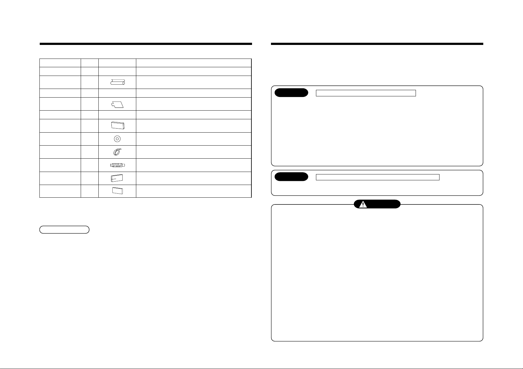
Accessory parts and Parts to be procured locally
H Accessory parts
Part name
Installation Manual
Heat insulating pipe
Q’ty
Shape
This manual
1
2
(Ensure hand over to customer)
For heat insulation of the pipe connecting section
Usage
1
PRECAUTIONS FOR SAFETY
• Ensure that all Local, National and International regulations are satisfied.
• Important safety information are described in this installation manual.
Please ensure this manual is read thoroughly and kept for future reference.
• After the installation work, perform a trial operation to check for any problem.
Follow the Owner’s Manual to explain how to use and maintain the unit to the customer.
• Turn off the main power supply switch (or breaker) before any unit maintenance.
• Ask the customer to keep the Installation Manual together with the Owner’s Manual.
20
Installation pattern
Installation gauge
Pattern fixing screw
Heat insulator
Washer
Hose band
Flexible hose
Heat insulator A
Heat insulator B
1
2
4
1
8
1
1
1
1
——
M5 × 16L
For checking of ceiling opening and the main unit position
For positioning of the ceiling position
(To be used with the installation pattern)
For attach the installation pattern
For heat insulation of drain connecting section
For hanging unit
For connecting drain pipe
For adjusting core-out of drain pipe
For sealing of wire connecting port
For sealing of wire connecting port
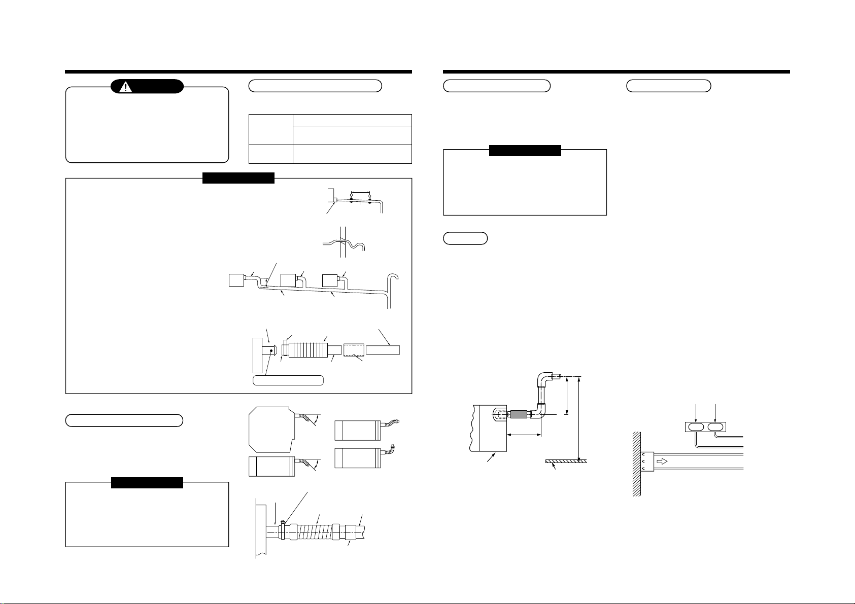
Refrigerant piping
• Piping material used for the conventional refrigerant cannot be used.
• Use copper pipe only with a wall thickness of 0.8 mm or more for Ø6.4, Ø9.5, Ø12.7.
• Flare nut and flare operations are also different from those of the conventional refrigerant.
Use the flare nut fitted to the indoor unit of the air conditioner.
CAUTION New Refrigerant Air Conditioner Installation
• THIS AIR CONDITIONER FEATURES A NEW HFC REFRIGERANT (R410A) WHICH DOES NOT
DEPLETE OZONE LAYER.
The pressure of R410A is 1.6 times higher than that of former refrigerant R22. The refrigerating oil has also been
changed. Therefore be sure that any former refrigerant, refrigerant oil or any other contaminants do not enter the
refrigerating cycle of the air conditioner, during either installation or service work. If incorrect tools or operating
procedures are used, there is a possibility of a serious accident. Use only tools and materials that have been
designed to operate with R410A.
To prevent the risk of charging with an incorrect refrigerant, the dimensions of the charging port connections are different
to those used for conventional refrigerant. Therefore only tools designed to operate with R410A can be used.
For connecting pipes, use piping specifically designed for R410A.
During installation, ensure pipes are clean and ensure contaminants do not enter in the pipes as the system is
affected by impurities such as water, oxide scales, dirt, oil, etc. Do not use existing pipe work from previous
installation as this will cause problems due to pressure resistances and impurities within the pipe.
CAUTION To Disconnect the Appliance from Main Power Supply.
This appliance must be connected to the main power supply by means of a switch with a contact separation of at
least 3 mm.
WARNING
• Ask an authorized dealer or qualified installation professional to install/maintain the air conditioner.
Inappropriate installation may result in water leakage, electric shock or fire.
• Turn off the main power supply switch or breaker before attempting any electrical work.
Make sure all power switches are off. Failure to do so may cause an electric shock.
• Connect all of the installation wiring correctly.
If the installation wiring is incorrect electrical parts may be damaged.
• During the transportation and installation of the air conditioning unit, ensure that gaseous matter
other than the specified refrigerant does not enter into the refrigeration cycle.
If a refrigerant becomes contaminated with foreign gases, the gas pressure within the refrigerant cycle will become
abnormally high and may result in the fracture of pipe work and possible human injury.
• Do not modify this unit by removing any of the safety guards or by overriding any of the safety
interlock switches.
• Exposure of the unit to water or other forms of moisture before installation may cause a short-circuit
of the electrical parts.
Do not store it in a wet basement or expose to rain or water.
• After unpacking the unit, examine for possible damage.
• Do not install in a place that might increase the vibration of the unit.
• To avoid personal injury (with sharp edges), be careful when handling parts.
• Perform installation work properly according to the Installation Manual.
Inappropriate installation may result in water leakage, electric shock or fire.
• When the air conditioner is installed in a small room, provide appropriate measures to ensure that in
the event of a refrigerant leak the rooms does not exceed the critical level.
Page 21
1
1000
or more
15 or more
15 or more
1000 or more
Obstacle
283
or more
283
or more
1000 or more
PRECAUTIONS FOR SAFETY
21
• Install the air conditioner securely in a location where the base can sustain the weight of the unit
adequately.
• Perform the specified installation work to guard against an earthquake.
If the air conditioner is not installed appropriately, accidents may occur due to the unit falling.
• If refrigerant gas has leaked during the installation work, ventilate the room immediately.
If the leaked refrigerant gas comes in contact with fire, noxious gases may be generated.
• After the installation work, confirm that refrigerant gas does not leak.
If refrigerant gas leaks into the room and flows near a fire source, such as a cooking range, noxious gases may be
generated.
• Electrical work must be performed by a qualified electrician in accordance with the Installation
Manual. Ensure the power supply to the air conditioner is exclusive to that unit only.
An insufficient power supply capacity or inappropriate installation may cause fire.
• Use only the specified wiring during the unit installation. Ensure that all terminals are securely fixed,
so preventing any external forces having a negative effect on the terminals.
• Conform to the regulations of the local electric authority when wiring the power supply.
Inappropriate grounding may cause an electric shock.
• Do not install the air conditioner in a location that may be subjected to a risk of exposure to a
combustible gas.
If a combustible gas leaks and becomes concentrated around the unit, a fire may occur.
2
SELECTION OF INSTALLATION PLACE
WARNING
• The air conditioner must be installed in a location that can support the weight of the unit effectively.
If the unit is not installed on a foundation that can support its weight effectively, the unit may fall down, resulting in
possible human injury.
• Where required ensure that the units installation is sufficient enough to withstand against an earthquake.
An insufficient installation could result in the unit falling, causing possible human injury.
• Install the air conditioner at a minimum height of 2.5 m from the floor.
Do not insert your hands or others into the unit while the air conditioner is operating.
CAUTION
Upon approval from the customer, install the air conditioner in a place that satisfies the following
conditions.
• A place where the unit can be installed horizontally.
• A place where a sufficient servicing space can be maintained for safety maintenance and unit check.
• A place where the drain water can be exited from the unit, without causing a problem.
Avoid installing in the following places.
• Places exposed to air with a high salt content (seaside area), or places exposed to large quantities of sulfide gas
(hot spring). (Should the unit be used in these places, special protective measures are needed.)
• Places exposed to oil, vapor, oil smoke or corrosive gas.
• Places where organic solvent is used nearby.
• Places close to a machine generating high frequency.
• Places where the discharged air blows directly into the window of the neighbouring house. (For outdoor unit)
• Places where the noise from the outdoor unit can be easily transmitted to the neighboring property.
(When installing the air conditioner on the boundary with a neighbor, pay due attention to the level of noise.)
• Places with poor ventilation.
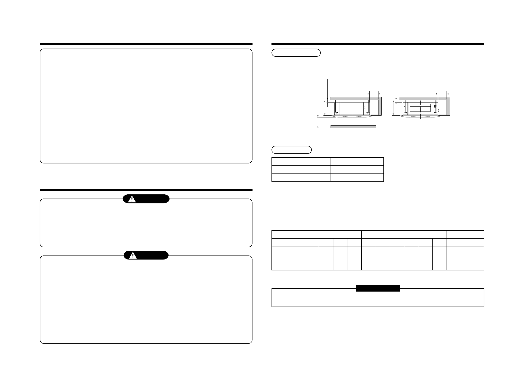
Installation space
Ensure there is sufficient space to install the unit and to perform maintenance work as and when required.
Keep 15mm or more for clearance between top plate of the indoor unit and the ceiling surface.
Installation space
Ceiling height
Model MMU-AP
0071 to 0121 type
0151 to 0181 type
When the ceiling height exceeds the standard distance of a 4-way air discharge cassette as detailed in the following
table. The air-flow may not be sufficient to heat the room. It is therefore necessary to set the unit to high ceiling
mode or adjust the direction of the ceiling discharge.
For setup of the high ceiling mode, refer to the details of Applicable controls “To incorporate a filter sold separately”
and “In case of installation to high ceiling” within this Manual.
Installable ceiling height list
Indoor unit capacity type
Discharge direction
Standard (At shipment)
High ceiling (2)
High ceiling (3)
Installable ceiling height
Up to 2.7 m
Up to 3.5 m
0071 to 0121 type 0151 type 0181 type
4-way 3-way 2-way 4-way 3-way 2-way 4-way 3-way 2-way
2.7 ——2.9 ——3.2 ——
———3.2 ——3.4 ——
———3.5 ——3.5 ——
Setup of high ceiling
Setup data
0000
0002
0003
(Unit: m)
REQUIREMENT
• When high ceiling (1) or (3) is used with 4-way blowing, a draft is easily recognized due to drop of discharge
temperature.
The air filter cleaning signal duration (Notification of filter cleaning) on the remote controller can be changed
according to the condition of installation.
If the room is not heated due to the installation place or construction of the room, the detection temperature of
heating can be raised.
For setup method, refer to “Change of lighting term of filter sign” and “Increased heating effect” in the Applicable
controls of this Manual.
Page 22
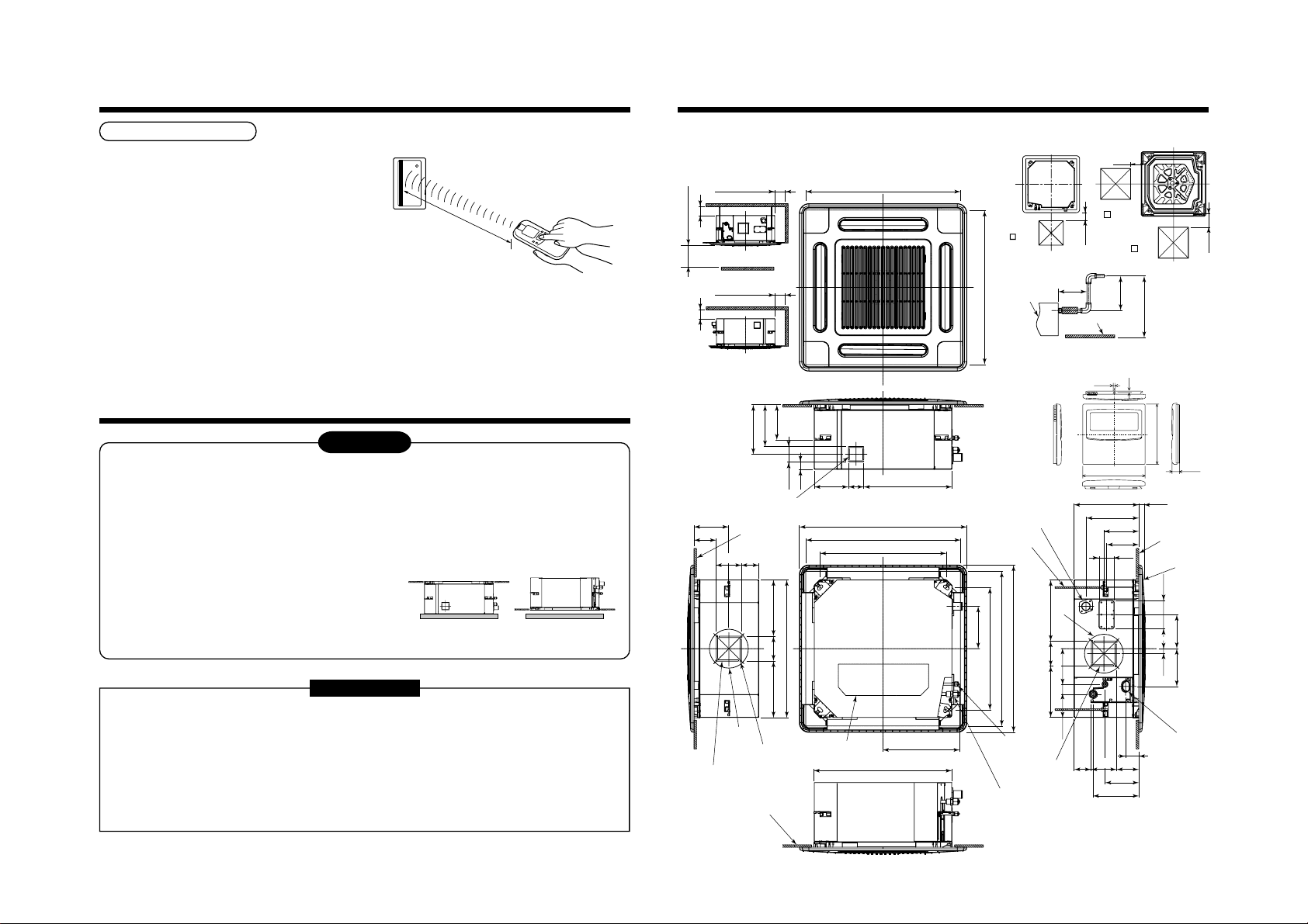
2
595 to 660 Ceiling open dimension
Space required for
installation and servicing
200
525 Hanging bolt pitch
595 to 660 Ceiling open dimension
700 Panel external dimension
142 64 368.5
145.5
93
105
70
575 Unit external dimension
320.5
595 to 660 Ceiling open dimension
Check port
(o 450)
Bottom face
of ceiling
Ceiling panel
Drain discharge port
Hanging bolt
M10 or W3/8
local arrange
Wiring connection
port
For 150 diameter
branch duct
knockout square hole
Knockout for 100 diameter
fresh air intake
Electric parts box
Ø162
For 150 diameter
branch duct knockout
square hole
4 screw holes
(For 4 mm tapping screw)
Bottom face
of ceiling
Bottom face of ceiling
Refrigerant pipe (Gas)
0151, 0181MH : Ø12.7
0071 to 0121MH : Ø9.5
Refrigerant pipe
(Liquid) Ø6.4
268 27
63
134
145.5
220.5
1000 or more
1000 or more
Obstacle
1000 or more
15 or more
15 or more
Drain-up standing-up size
Note)
As ABS is used for the drain discharge port of the main unit,
the vinyl chloride paste cannot be used.
Use the flexible hose (Band fix) included in the package.
Stand-up
627.5
or less
Ceiling
Indoor unit
Stand-up
850 or less
300 or less
55
9310570
139.5
190.5
21
158
214 105
177
207
575 Unit external dimension
105235 235
175
149
64
29
525 Hanging bolt pitch
595 to 660 Ceiling open dimension
700 Panel external dimension
256
Ø162
142
120
97.5 42 148
200
200
Check port
( 450)
Check port
( 450)
16
120
4
2.7
120
• Wired remote
controller
(RBC-AMT31E)
SELECTION OF INSTALLATION PLACE
In case of wireless type
The wireless remote controller can be operated up to a
maximum of 8 m from the infra-red receiver.
Therefore ensure that the remote controller will be
mounted and used within this stated parameter.
• To prevent malfunction do not mount or operate in a
location that is subjected to either a fluorescent lamp
or direct sunlight.
22
• A maximum of 6 indoor units with wireless remote
controller can be installed within the same room.
3
The installation of the air conditioning unit must be positioned in a location that can sufficiently support its weight
and give protection against adverse environmental conditions.
Failure to do so may result in unit damage and possible human injury.
Any incomplete installation may also cause possible risk of human injury.
• Unpack the package, take out the product and then place it on the floor so that the same surface directs
• Never put the products taken out from the packing box in a
Strictly comply to the following rules to prevent damage of the indoor units and human injury.
• Do not place heavy objects on the indoor unit. (Even when units are still packaged)
• Always carry the unit as packaged from the factory wherever possible.
• To move the indoor unit, hold the hanging brackets (4 positions) only.
• To be carried by two or more persons. Do not strap the unit in positions other than that stated.
8 m or less
INSTALLATION OF INDOOR UNIT
underneath as it is placed in the package.
WARNING
pile, or put other load on them; otherwise there is a
possibility to damage electric parts, fan parts, draining
mechanism, and etc.
If the both sides are turned over, a deformation of mounting
metal of the ceiling panel which is sold separately, etc may
be caused. Accordingly the product may be damaged and
OK NO GOOD
the installation becomes impossible in some cases.
REQUIREMENT
If carrying in the indoor unit unpacked by necessity, be sure to use buffering cloth, etc. to prevent damaging
the unit.
Do not apply force to other parts (refrigerant pipe, drain pan, foamed parts, or resin parts etc.).
Dimensional view
Page 23
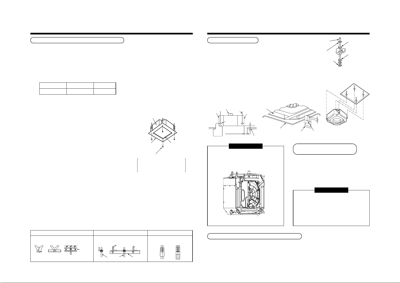
3
Hanging bolt
(W3/8 or M10)
Nut
(W3/8 or M10)
(1) M10 washer supplied, all other material
must be procured locally.
(2) To ensure that the unit is mounted safely, the
hanging bolt must be positioned just below
the hanging bracket as shown in the diagram.
(1)
M10 flat washer
(Accessory)
(2)
M10 flat washer
(Accessory)
Nut
(W3/8 or M10)
Installation gauge 2) 10 to 42 mm
1) 23 to 28 mm
Ceiling panel
Indoor unit
INSTALLATION OF INDOOR UNIT
23
Ceiling opening and installation of hanging bolts
• Evaluate and determine the piping and wiring requirements inside the ceiling prior to the hanging of the unit.
• After installation place of the indoor unit has been determined, create opening in ceiling and install the hanging
bolts.
• For the ceiling opening size and pitch for hanging bolts refer to the dimensional drawing and the supplied
installation pattern.
• Once the ceiling void has been created, ensure that the drain pipe, refrigerant pipes, inter-connecting wires and all
control wires are in place prior to installing the actual indoor unit.
Please procure the hanging bolts and nuts for installation of the indoor unit at local site.
Hanging bolt
Nut
M10 or W3/8
M10 or W3/8
4 pieces
12 pieces
How to use the supplied installation pattern
The installation pattern is enclosed within the packaging of the air conditioner.
Existing ceiling void
Use the pattern to determine the position and size of the opening and
Indoor unit
location of the hanging bolts.
New ceiling void
Use the pattern to determine the position of the new ceiling opening.
Cut off slit section of the main unit of the installation pattern.
Cut off the outside of the pattern according to size of the ceiling
opening. (There is a slit on the standard opening size section.)
• Install the indoor unit after installation of the hanging bolts.
• Using the supplied pattern attach it to the indoor unit using the
supplied fixing screws (M5 × 16L 4off). (Screw pattern to the ceiling
panel hanging brackets of the indoor unit)
• When creating the opening ensure it is as per the outer dimensions
of the supplied pattern.
Installation pattern
(Attached)
M5 × 16L screws (Attached)
These screws are exclusive to the
installation pattern. When installing
the ceiling panel, the other exclusive
screws attached to the ceiling panel
(sold separately) are used.)
Cut off the installation
pattern along slit of
the main unit.
Treatment of ceiling
The ceiling differs according to the structure of the building. For details, consult your architect.
In the process after the ceiling panels have been removed, it is important to reinforce the ceiling construction and
ensure the ceiling remains in a horizontal position. This is to prevent possible vibration of the ceiling panels.
1. Cut and remove the ceiling material.
2. Reinforce the cut surface of the ceiling construction and add support for fixing the end of ceiling panel.
Installation of hanging bolt
Use M10 hanging bolts (4 off, locally procured).
When mounting the unit, set the pitch of the hanging bolts according to the size of the unit as detailed on the
dimensional drawing.
New concrete slab
Install the bolts with insert brackets or anchor
bolts.
(Blade type
bracket)
(Slide type
bracket)
(Pipe hanging
anchor bolt)
Anchor bolt
Reinforcing
steel
Steel flame structure
Use existing angles or install new
support angles.
Hanging bolt
Hanging bolt Support angle
Existing concrete slab
Use a hole-in anchors, hole-in
plugs, or a hole-in bolts.
Installation of indoor unit
• Attach the nut (M10 or W3/8: Procured locally) and washer (Ø34 mm)
to the hanging bolt.
• Put washers at either side of the T-groove on the hanging bracket of
the indoor unit in order to hang the unit.
• Using a spirit level, check that all four sides are horizontal.
(Horizontal positioned within 5 mm)
• Cut off the installation gauge from the installation pattern.
• Using the installation gauge check and adjust clearance between the
indoor unit and the ceiling opening (1) (10 to 42 mm on each side).
Ensure that the unit is level to the ceiling and within a distance of (2)
23 mm to 28 mm below.
The installation gauge has details of how to use printed on it.
Note) Install the indoor unit so that the end part of opening does not
come into contact with the drain socket piping.
Level vial (Horizontal: within 5 mm)
Indoor unit
Hanging
metal
10 to 42
Installation gauge
Before installation of the indoor unit be sure to
remove the transportation cushion found between
the fan and the bell mouth.
Running the unit without removing the cushion
may damage the fan motor.
Hanging bolt
23 to 28 mm (1)
mm (2)
Ceiling board
REQUIREMENT
Installation of ceiling panel
(Sold separately)
Install the ceiling panel after completion of the
installation of the indoor unit, including all piping and
wiring.
Install the ceiling panel as per the supplied Installation
Manual.
Check the installation dimensions of the indoor unit
and the ceiling opening are correct and then install.
REQUIREMENT
Ensure the ceiling panel is mated to the ceiling
surface or the indoor unit.
If the panel and unit are not mated together this
may result in the formation of dew condensation
causing a possible water leak.
Be sure to remove the cushion for transportation
between the fan and the bell mouth.
First remove the 4 corner caps from the ceiling
panel and fit to the indoor unit.
Installation of remote controller (Sold separately)
For installation of the wired remote controller, follow the Installation Manual supplied with the remote controller.
• Do not expose remote controller to direct sunlight or excessive heat.
• When using a wireless type remote controller check receiver on the indoor unit receives a signal.
• For a wireless type controller ensure that it is used and mounted a minimum distance of 1m apart from any other
electrical devices (TV, Stereo, etc). As this may cause interference with the devices.
Page 24
4
Rising up
627.5mm or less
Rising up 850mm or less
300mm
or less
Indoor unit
Underneath of ceiling
220–240V, 1N ~, 50Hz
220V 1N ~, 60Hz
White
Black
CN34
(RED)
Black
Red
Pull out connector CN34 (Red) from P.C. board.
R(L) S(N)
DRAIN PIPING WORK
24
CAUTION
• Install the drain piping so that the water
drains effectively.
• Apply heat insulation to prevent dew
condensation from forming.
Pipe material/Insulator and size
The following materials for piping work and insulation
are to be procured locally.
Pipe material
• Incorrectly installed pipe work may result
in a water leak.
Insulator
REQUIREMENT
• Ensure insulating of the drain pipes and connecting parts on the indoor units.
• The drain pipe should have a downward slope of at least 1/100 and ensure
there are no swells or blockages as this will cause abnormal sounds.
• The maximum traverse length of drain pipe is 20 m. Provide support
brackets at intervals of 1.5 to 2 m where necessary to prevent movement.
• Install the combined piping as shown in the illustration.
• Do not create an air purge in the pipework,
as the water would leak from this point.
(Collective pipes)
• The hard vinyl-chloride pipe cannot be connected
directly to the drain pipe connecting port of the indoor unit.
For connection with the drain pipe connecting port,
ensure that the supplied flexible hose is fitted.
• Adhesive agent cannot be used for the pipe
connecting port (hard socket) on the indoor unit.
Be sure to use the supplied hose band for fixing,
otherwise there is a risk of damage or water
leakage from the drain pipe connecting port.
As long as possible (10cm)
VP25
VP30 or more
Drain pipe connecting port
(Hard socket)
Attached hose band
Soft socket Hard socket
Adhesive agent prohibited
Hard vinyl chloride pipe socket for VP25
Hard vinyl chloride pipe VP25
(Outer diameter Ø32 mm)
Foamed polyethylene foam, thickness:
10 mm or more
Heat
insulator
1.5m to 2m
1/100 or more
downward
Arched
shape
Support
bracket
NO
GOOD
Tra p
VP25
VP25
Downward slope
1/100 or more
VP25 vinyl chloride pipe
(Procured locally)
Attached flexible hose
Socket for VP25
(Procured locally)
Connection of drain pipe
• Connect the hard socket (Procured locally) to the
hard socket side of the supplied flexible hose which
has been installed.
• Connect the drain pipes (Procured locally) in turn to
the connected hard sockets.
REQUIREMENT
• Using an adhesive agent for vinyl chloride,
connect the hard vinyl chloride pipes so that
water does not leak.
• Allow sufficient time for the adhesive to set and
harden. (Refer to the instructions of the
adhesive.)
Drain up
When it is not possible to achieve a natural downward
slope on the drain pipe, you can create a vertical lift
(Drain up) on the pipe.
• Set the height of the drain pipe within 850 mm from
the bottom surface of the ceiling.
• The drain pipe should be piped from the drain pipe
connecting port horizontally for a maximum of
300 mm and then piped vertically.
• After piping the vertical lift, ensure the pipe work is
set to a downward gradient.
Check the draining
After completion of drain piping,
Check water drains away and that no water leaks from
any of the connecting parts. At the same time check
for any abnormal sounds from the drain pump.
Ensure drainage is checked during cooling mode.
When the electric work has finished:
• Before installing the ceiling panel, pour water as
shown in the following figure, check water drains
from the drain pipe connecting port (Transparent) in
COOL mode and then check there are no water
leaks from the drain pipes.
When the electric work has not finished:
• Pull out the float switch connector (3P: Red) from
P.C. board connector (CN34: Red) of the electric
parts box. (Ensure the power is turned off.)
• Connect the single-phase 220-240V, 1N, 50Hz (or
220V, 1N, 60Hz) power to the terminal blocks R (L)
and S (N). (Never apply 220-240V to (A), (B), (U1)
and (U2).)
• Pour water referring to the next page figure.
(Amount: 1500 cc to 2000 cc)
• When the power is turned on, the drain pump motor
drives automatically. Check water is drained from
the drain pipe connecting port (Transparent), and
then check there is no water leak from the drain
pipes.
• After checking for water leaks on the drain, turn off
the power supply, and re-attach the float switch
connector to the original position (CN34) on the P.C.
board and refit the electric parts box.
Connection of flexible hose
• Insert the soft socket of the supplied flexible hose
into the connecting port of the drain pipe.
• Align the supplied hose band to the pipe connecting
port end, and tighten.
• Fix the soft socket with the supplied hose
band, tighten at the upper position of the
unit.
• The supplied flexible hose can bend up to
a maximum of 45°
REQUIREMENT
Drain pipe
connecting port
(Transparent)
Indoor unit body
max
45˚
NO GOOD
OK
max
45˚
Align the attached hose band to the
end of hose, set the tightening
position upward, and then tighten it.
Flexible hose
(Accessory)
VP25 vinyl chloride pipe
(To be local procure)
Socket for VP25 vinyl chloride pipe
(To be local procure)
Riser (Trap)
90˚ Bend
Page 25
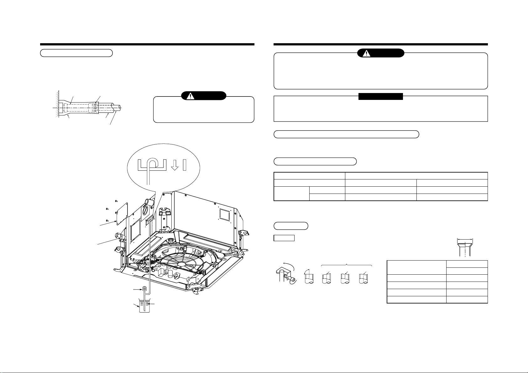
4
90˚
Obliquity Roughness Warp
NO GOODOK
DRAIN PIPING WORK
5
REFRIGERANT PIPING
25
Thermal insulating process
• After checking of the draining, using the supplied thermal insulation fit to the flexible hose leaving no clearance at
the connecting port of the indoor unit.
• Fit locally procured thermal insulation to the drain pipe leaving no clearance between the supplied insulation.
Flexible hose
Attached heat insulator
Check panel
Hose band
Heat insulator to be
procured locally
Hard vinyl chloride pipe
CAUTION
Ensure water is poured slowly.
To reduce risk of water spreading throughout the
unit, resulting in a possible fault.
Air
discharge area
Drain pan
WARNING
• If refrigerant gas leaks during the installation work, ventilate the room immediately.
• If the leaked refrigerant comes in contact with fire, noxious gas may generate.
• After the installation work, confirm that refrigerant does not leak.
• If refrigerant gas leaks into the room and flows near to a source of fire, noxious gas may be generated.
REQUIREMENT
When using long length of refrigerant piping. Provide support brackets at intervals of 2.5 m to 3 m.
If the pipes are not fixed abnormal sounds may be generated.
Ensure the supplied R410A flare nuts are used.
Permissible pipe length and permissible height difference
This differs depending on the outdoor units. For details, refer to the Installation Manual supplied with the outdoor
unit.
Piping material and dimensions
Piping material
Indoor unit capacity type MMU-
Pipe size (mm)
• Use new and clean pipe, ensuring that the pipes are not contaminated with dust, oil, moisture, etc.
Gas side
Liquid side
Pipe flaring
Phosphor deoxidization seamless pipe for air conditioner
AP0071 to AP0121 type AP0151 to AP0181 type
Ø9.5 Ø12.7
Ø6.4 Ø6.4
Insert the leading part of the
hose between the heat
exchanger and the drain pan,
and then bend it downward.
Polyethylene hand pump for
pouring water in drain pan
Vessel
Water (1500cc to 2000cc)
Flaring
1. Cut the pipe with a pipe cutter.
2. Place flare nut onto the pipe, and flare the pipe.
(Use the flare nut fitted to the unit or one that is
R410A compatible)
As the flaring sizes of R410A differ from that used
on R22. It is recommended to use a dedicated
R410A flaring tool. However a conventional flare
tool can be used, by adjustment of the projection of
the copper pipe.
• Flaring diam. meter size :
A (Unit : mm)
Outer diam. of copper pipe
6.4
9.5
12.7
15.9
In case of flaring for R410A with the conventional
*
flare tool, make a margin of 0.5 mm longer than that
of R22 pipe so that the flare size matches with the
specified size.
The copper pipe gauge is useful for adjusting the
projection margin size.
A
+0
A
- 0.4
R410A
9.1
13.2
16.6
19.7
Page 26
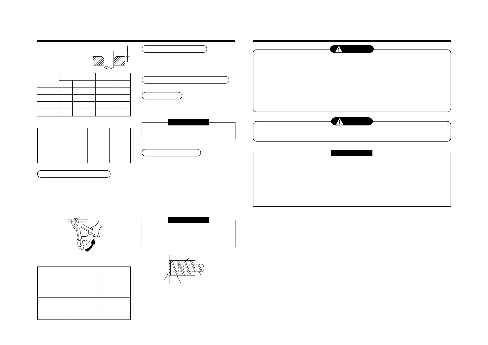
5
REFRIGERANT PIPING
6
ELECTRIC WORK
26
• Projection margin in flaring :
B (Unit : mm)
Rigid (Clutch type)
Outer diam. of
copper pipe
6.4
9.5
12.7
15.9
Imperial (Wing nut type)
Outer diam. of copper pipe
R410A tool used
R410A R22
0 to 0.5 (Same as left)
0 to 0.5 (Same as left)
0 to 0.5 (Same as left)
0 to 0.5 (Same as left)
6.4
9.5
12.7
15.9
Conventional tool used
R410A R22
1.0 to 1.5 0.5 to 1.0
1.0 to 1.5 0.5 to 1.0
1.0 to 1.5 0.5 to 1.0
1.0 to 1.5 0.5 to 1.0
R410A R22
1.5 to 2.0 1.0 to 1.5
1.5 to 2.0 1.0 to 1.5
2.0 to 2.5 1.5 to 2.0
2.0 to 2.5 1.5 to 2.0
Connection of refrigerant pipe
Connect all the refrigerant pipes with the flare
connection method
• As the unit is sealed to atmospheric pressure.
It is not abnormal that no “Push....” sound will be
heard upon the removal of the flare nut.
• Ensure use of two spanners for the connecting of the
pipe work to the indoor unit.
B
Airtight test/Air purge, etc.
For carrying out airtight test, air purge, gas leak check
and addition of refrigerant refer to the Installation
Manual supplied with the outdoor unit.
Open fully valves of the outdoor unit
Gas leak check
Using a leak detector or soapy water, check for gas
leaks at the connecting pipe work and the caps on the
service valves.
REQUIREMENT
Use a leak detector designed specifically for HFC
refrigerant (R410A, R134a, etc.).
Heat insulating process
Fit heat insulation to the gas and liquid pipes
separately.
During cooling mode, the temperature of the liquid and
the gas pipes are reduced. Therefore ensure sufficient
insulation is fitted to prevent dew condensation.
• On the gas side ensure that the heat insulation used
is heat resistant to a minimum temperature of 120°C
• Using the supplied heat insulation. Insulate the
interconnecting parts of the indoor unit, ensuring that
there is no exposure of any refrigerant pipe work.
As detailed in the illustration below.
REQUIREMENT
Apply the thermal insulation to the pipe connecting
section of the indoor unit securely up to the root
without exposure of the pipe. (The pipe exposed to
the outside causes water leak.)
WARNING
1. Using the specified wires, ensure the wires are connected and securely fixed so that no
external force can transmit to the connecting part of the terminals.
Poor connection may cause risk of fire, etc.
2. Ensure connection of earth wire. (Grounding work)
Do not connect the earth wire to a gas pipe, mains water pipe, lightning rod, or the earth wire of a telephone.
Incorrect earthing will cause risk of an electric shock.
3. For electrical installation work, strictly follow the Local and national Regulations of each
country and the Installation Manual. A designated power supply must be used.
Capacity shortage of the power supply or incomplete installation may cause an electric shock or a fire.
CAUTION
Ensure an earth leakage breaker is installed.
Failure to install, may result in an electric shock.
REQUIREMENT
• For power supply wiring, strictly conform to the Local authorities in each country.
• For wiring of the power supply of the outdoor units, follow to the outdoor unit Installation Manual.
• Never connect 220–240V control wiring to the terminal blocks (U1, U2, A, B) fault will be. (Caused.)
• Arrange the electrical wiring so that they do not come into contact with high-temperature parts of the pipe
work; this is to prevent the risk of insulation melting and causing a possible accident.
• After connecting wires to the terminal block. Secure wiring with cable clamp.
• Store wiring install control wiring and refrigerant piping within the same line.
• Do not turn on power of the indoor unit until vacuuming of the refrigerant pipe has finished.
Work using double spanner
• Refer to the following table for tightening torque.
Connecting pipe
outer dia. (mm)
Ø6.4
Ø9.5
Ø12.7
Ø15.9
Tightening torque
(N•m)
14 to 18
(1.4 to 1.8 kgf•m)
33 to 42
(3.3 to 4.2 kgf•m)
50 to 62
(5.0 to 6.2 kgf•m)
68 to 82
(6.8 to 8.2 kgf•m)
Re-tightening
torque (N•m)
18
(1.8 kgf•m)
42
(4.2 kgf•m)
50
(5.0 kgf•m)
68
(6.8 kgf•m)
Main unit
Attached heat insulating pipe
Set notching upward.
Pipe side
(Required at the site)
Page 27
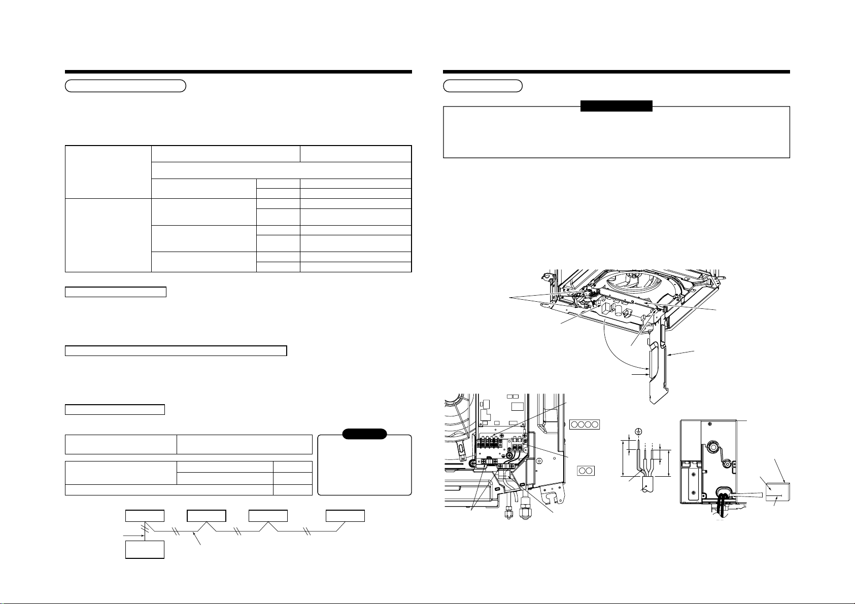
6
P.C. board
Cover of electric parts box
Hooking section
Screw
Screws
Electric parts box
Thermal insulation to cabling connecting port
R
(L)
S
(N)
10
10
50
70
Earth line
Connecting
cord
R(L) S(N)
Cord clamp Heat insulator B
Heat insulator A
Indoor/Outdoor
crossover cable/
Remote controller
terminal block
Power supply
terminal block
U1U2A B
Adhered surface
Notched section
ELECTRIC WORK
Power supply specifications
Power supply wiring and communication wiring are to be procured locally.
For the power supply specification, follow the table below. Ensure power supply is adequate. An insufficient power
supply could result in unit failure.
For specification of the power capacity of the outdoor unit and the power supply wires, refer to the Installation
Manual supplied with the outdoor unit.
Indoor unit power supply (*1)
Communication line
27
Indoor unit power supply (*1)
• Indoor unit power supply, must have a dedicated supply and be separate to that of the outdoor unit.
• Arrange the power supplies to the indoor and outdoor units, so that a common earth leakage breaker and main
switch can be used.
• Power supply cable specification : Cable 3-core 2.5 mm², in conformity with Design 60245 IEC 57.
Indoor/Outdoor inter-unit wiring, Central controller wiring (*2) (*3)
• Use a 2 core non polarity cable.
• To prevent any possible noise issues, use a shielded 2 core wire.
• The total stated length of communication wiring is determined by the interconnecting length of indoor to outdoor
cable plus the length of the central control communication cable.
Remote controller wiring (*4)
• For wiring remote controllers, a 2 core polarity cable must be used.
Remote controller wiring, remote
controller inter-unit wiring
Total wire length of remote controller
wiring and remote controller inter-unit
wiring = L + L1 + L2 + … Ln
Total wire length of remote controller inter-unit wiring = L1 + L2 + … Ln
Remote
controller
wiring
Power supply
Power supply switch/Earth leakage breaker or power supply wiring/fuse rating for indoor
units should be selected by the accommodated total current values of the indoor units.
Power supply wiring
Indoor/Outdoor inter-unit wiring (*2)
Central control line wiring (*3)
Remote controller wiring (*4)
Indoor unit
Remote
controller
20 m or less Twist wire : 2.5 mm²
50 m or less Twist wire : 3.5 mm²
Q’ty 2
Wire size
Q’ty 2
Wire size
Q’ty 2
Wire size Twist wire : 0.5 to 2.0 mm²
Twist wire: 0.5mm
In case of wired type only
In case of wireless type included
Indoor unit
L1 L2 Ln
Remote controller inter-unit wiring
2
to 2.0 mm2 × 2
Up to 500 m
Up to 400 m
Up to 200 m
Indoor unit Indoor unit
220–240V, 1N ~ 50Hz
220V, 1N ~ 60Hz
(Up to 1000 m) Twist wire : 1.25 mm²
(Up to 2000 m) Twist wire : 2.00 mm²
(Up to 1000 m) Twist wire : 1.25 mm²
(Up to 2000 m) Twist wire : 2.00 mm²
CAUTION
The remote controller wire
(Communication line) and AC220–
240V (Power supply) wires cannot
be parallel to contact each other
and cannot be stored in the same
conduits. If doing so, a trouble
may be caused on the control
system due to noise, etc.
(Max. 8 units)
Cable connection
REQUIREMENT
• Be sure to locate the cable through the cable connection port of the indoor unit.
• Ensure additional wire length of approximately 100 mm at the indoor unit electric parts box.
This is to enable ease of any service work in the future.
• The low-voltage circuit is provided for the remote controller.
• Remove the cover of the electric parts box by removing the mounting screws (3 pcs.) and push the hooking
section. (The cover of the electric parts box remains hanged to the hinge.)
• Tighten the screws on the terminal block and secure the cables with cord clamp fitted to the electric parts box.
(Do not apply tension to the connecting section of the terminal block.)
• Using the supplied thermal insulation for the sealing of the cable connecting port, seal the cable connecting port.
(Otherwise dew condensation may be caused.)
• Mount the cover of the electric parts box ensuring the cables are not pinched.
(Mount the cover after the ceiling panel has been wired to the electric box.)
Page 28
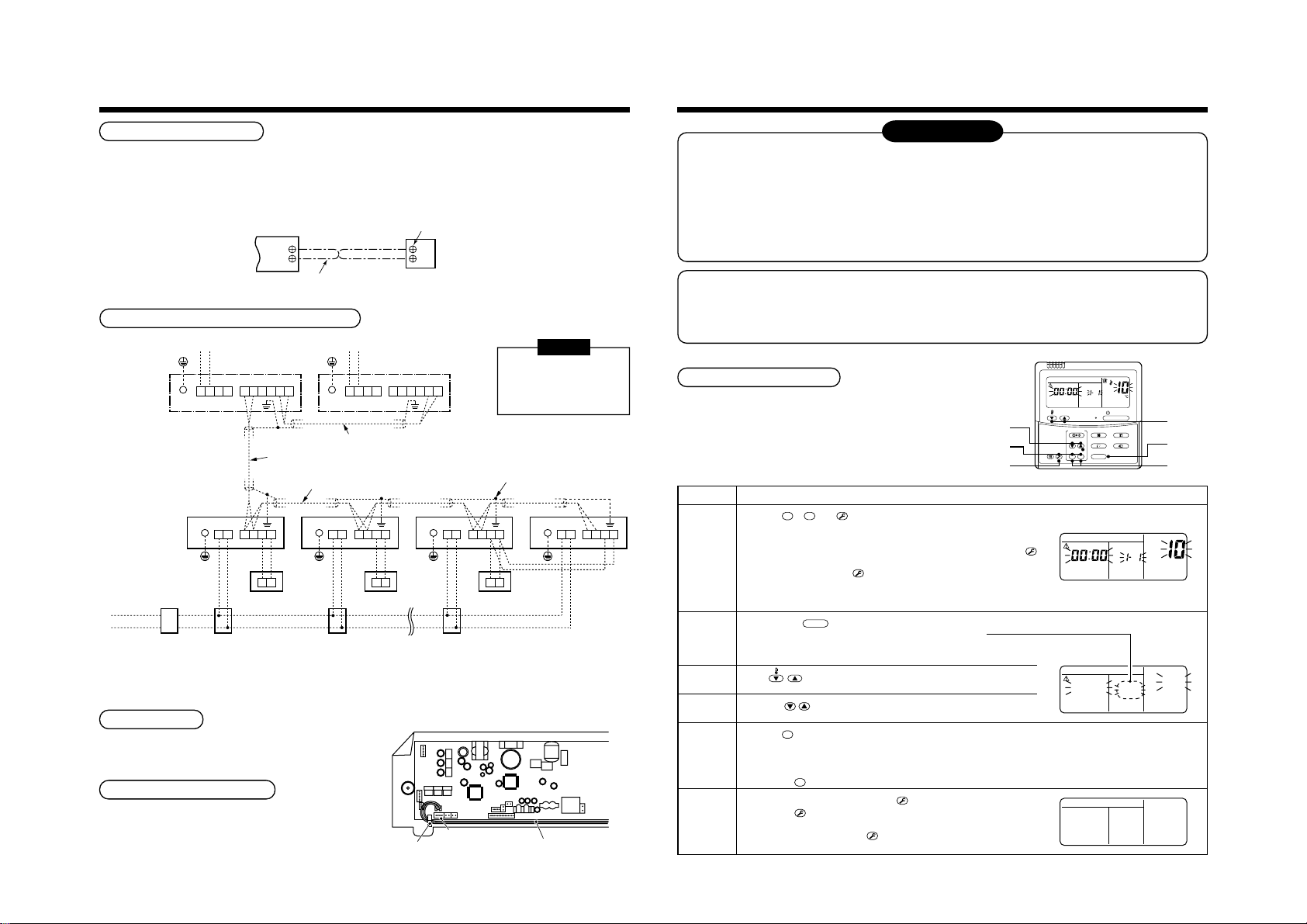
6
ON / OFF
FAN
TEMP.
SWING/FIXTIME
MODE
VENT
UNITSET CL
FILTER
RESET
TEST
TIMER SET
CODE No.
UNIT No.
R.C. No.
1
2
3
5
6
6
T
T
T
T
T
T
CODE No.
UNIT No.
R.C. No.
∗
∗∗
∗∗
∗
∗∗∗∗∗
CODE No.
UNIT No.
SETTING
R.C. No.
ELECTRIC WORK
7
APPLICABLE CONTROLS
Remote controller wiring
• Strip approximately 14 mm of insulation off of the connecting wires.
• As the remote controller wire has no polarity, there is no problem if connections to indoor unit terminal blocks A
and B are reversed.
Wiring diagram
Terminal block for remote controller
wiring of indoor unit
A
B
Remote controller wire (Field supply)
Terminal block
A
B
Remote
controller unit
When using the equipment for the first time, the remote controller will not accept any commands for a short
period of time.
• Automatic address
• While automatic addressing no operations can be performed on the remote controller.
• Automatic addressing will take a maximum duration of 10 minutes (generally 5 minutes).
• Upon turning on the unit after completion of automatic addressing, a maximum period of
10 minutes (generally 3 minutes) are required prior to the start up operation of the outdoor unit.
All indoor units are shipped from factory as standard. Change if necessary.
NOTIFICATION
To change the setup use the main remote controller (wired remote controller).
Wiring between indoor and outdoor units
Outdoor power supply
Follower outdoor unit
U2U1 A B
BA
Remote
controller
U1U2 U3 U4U5 U6
Indoor unit
Earth
Earth
Control wiring between outdoor units
Control wiring between indoor units
Indoor unit
Earth
LN U2U1 A B
Pull box
NOTE
An outdoor unit that is
inter-connected to the
indoor units automatically
becomes the header unit.
Connection of shield wire closed terminal
Indoor unit
LN U2U1 A B
Remote controller
[Group control]
Pull box
Earth
LN
BA
28
Indoor power supply
220-240V, 1N ~50Hz
220V, 1N ~60Hz
Earth leakage
breaker
Power switch
Outdoor power supply
Earth
Indoor unit
Earth
LN
Pull box
Header outdoor unit
U1U2 U3 U4U5 U6
Control wiring between indoor and outdoor units
U2U1 A B
BA
Remote
controller
Address setup
Set up the addresses as per the Installation Manual
supplied with the outdoor unit.
Wiring on the ceiling panel
As per the Installation Manual of the ceiling panel,
connect the connector (2P: Red) of the ceiling panel to
the connector (5P: White) onto the P.C. board within
the electric parts box.
Cord Clamp
5P connector (White)
Wire from ceiling panel
* The setup change for wireless remote controller, sub remote controller or a unit without a controller (Centrally
controlled.) is not possible. In such cases, temporarily install a separate main remote controller.
Applicable control setup
Basic operation procedure for setup change
Change the setup while operation of the equipment is stopped.
(Be sure to stop the operation of a set.)
Procedure
1
2
3
4
5
6
SET
Push the
as shown in the figure.
Check that the displayed item code is [10].
• If the item code indicates any characters other than [10], push the
button to erase the display and retry the operation from the first step.
(For some time after the
of the remote controller cannot be accepted.)
(In a group control, the firstly displayed
indoor unit No. becomes the center unit.)
Each time the
Select the indoor unit that requires a change to the setup.
During this time the indoor unit that is selected can be
confirmed as the louver and fan will be operated.
TEMP.
Using
Using the
SET
Push the
complete.
• To change the setup of an indoor unit that is not selected, restart operation from Procedure
• To change to a different setup within the selected indoor unit, restart operation from Procedure
Pushing the
When the setup is finished, push the
Pushing the
normal stopped status.
(For a period of time after the
controller will not accept any commands.)
TES
, CL and
TIME
button. During this time, if the display changes from flashing to permanently on, the setup is
CL
TES
buttons simultaneously for 4 seconds or more, after a while, the display part flashes
TES
button has been pushed, the operation
UNIT
button is pushed, the indoor unit No. in the group control is displayed consecutively.
the buttons, select the item code [**].
buttons, select set data [
button clears the set up contents which has been set. In this case, restart from Procedure 2.
button deletes the display and returns the status to the
TES
TES
button has been pushed, the remote
Description
TES
(* The display changes according
].
****
button. (The setup is configured.)
to the indoor unit model.)
2
.
3
.
Page 29
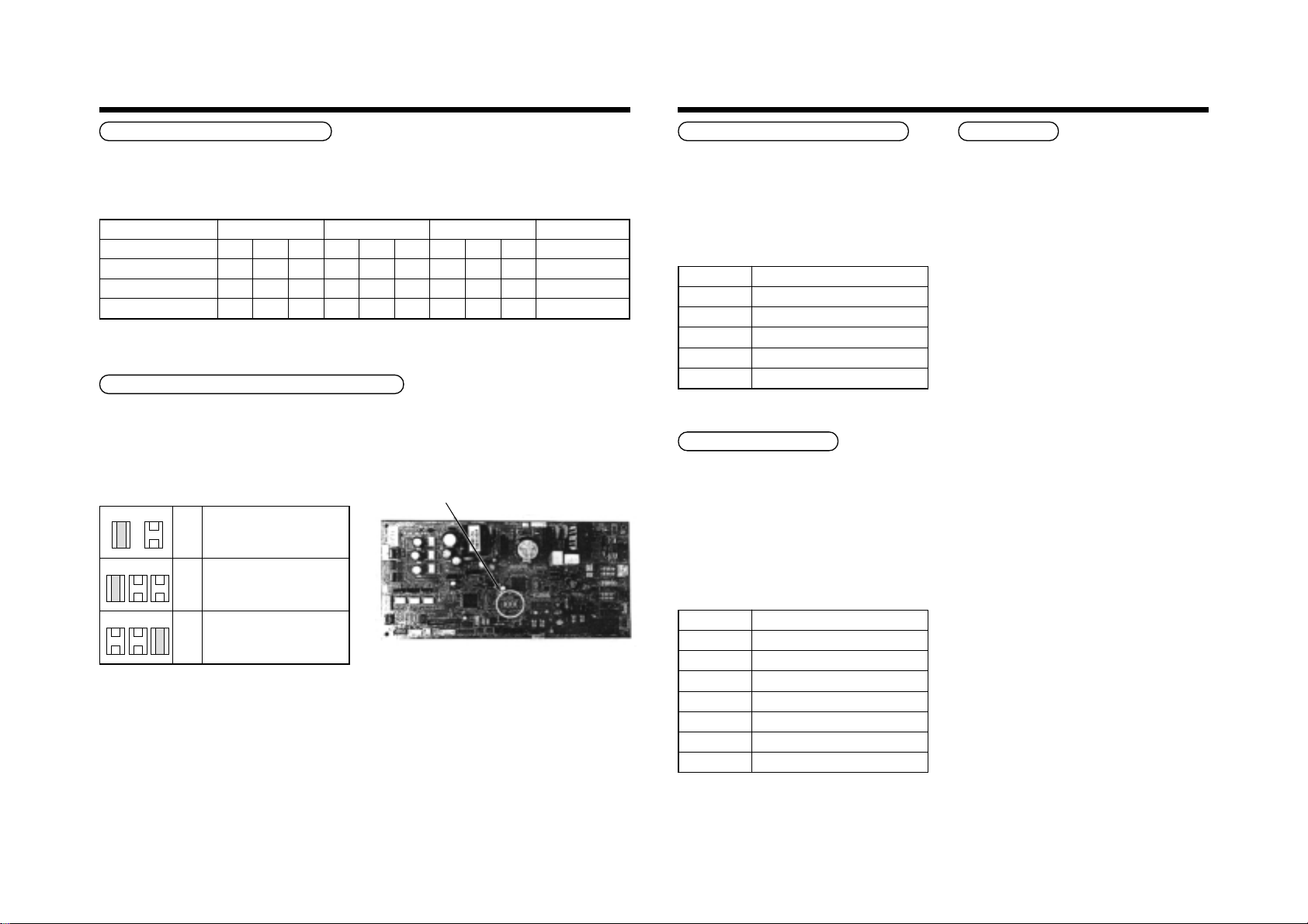
7
APPLICABLE CONTROLS
29
In case of installation to high ceiling
When the unit is to be installed at a height that exceeds the standard value, adjustment to the air volume is
necessary.
2
• For the “Setup data” in Procedure
, select from the “Installable ceiling height list”.
Installable ceiling height list
Indoor unit capacity type
Discharge direction
Standard (At shipment)
High ceiling (2)
High ceiling (3)
0071 to 0121 type 0151 type 0181 type
4-way 3-way 2-way 4-way 3-way 2-way 4-way 3-way 2-way
2.7 ——2.9 ——3.2 ——
———3.2 ——3.4 ——
———3.5 ——3.5 ——
Setup of high ceiling
Setup data
0000
0002
0003
(Unit: m)
In case of remote controller-less (Group control)
To set the unit to high ceiling operation, there is a method that requires the changing of the short plugs on the indoor
P.C. board. The details are shown in the below table.
This method is only to be used where a standard wired remote controller (Group control) is not used.
∗ Upon changing the high ceiling setting
• Select setting by the changing of the short plugs
on the indoor P.C. board.
Short plug position
Short
CN112 CN111 CN110
CN112 CN111 CN110
Open
Set
data
0000
0003
Filter sold separately
Standard filter (At shipment)
High ceiling (3)
• Short plug position
(CN112, CN111, CN110 from the left)
Change of lighting time of filter sign
Depending on the conditions of the installation, the
time period of the filter clean sign can be changed.
Follow to the basic operation procedure
1
→ 2 → 3 → 4 → 5 → 6 ).
(
• For the item code in Procedure
• For the [Set data] in Procedure
3
, specify [01].
4
, select the setup
data of filter sign lighting time from the following
table.
Setup data
0000
0001
0002
0003
0004
Filter sign lighting time
None
150H
2500H (At shipment from factory)
5000H
10000H
Increased heating effect
If it is not possible to achieve satisfactory heating due
to the installation environment or the structure of the
room. The detected temperature can be increased.
Also use a circulator, etc to circulate hot air near the
ceiling.
Follow to the basic operation procedure
1
→ 2 → 3 → 4 → 5 → 6 ).
(
• For the item code in Procedure
• For the set data in Procedure
data of the required temperature shift value from the
table below.
Setup data
0000
0001
0002
0003
0004
0005
0006
Detection temp shift value
+1°C
+2°C (At shipment from factory)
+3°C
+4°C
+5°C
+6°C
3
, specify [06].
4
, select the setup
No shift
Group control
In a group control, a remote controller can control up
to a maximum of 8 units.
• For cabling procedure and cables of the individual
line (Identical refrigerant line) system, refer to
“Electric work” in this Manual.
• Wiring between indoor units in a group is performed
in the following method.
Connect the indoor units by connecting the remote
controller inter-unit cables from the remote controller
terminal blocks (A, B) of the indoor unit connected
with a remote controller to the remote controller
terminal blocks (A, B) of the other indoor unit.
(No polarity)
• For address setup, refer to the Installation Manual
supplied with the outdoor unit.
Page 30
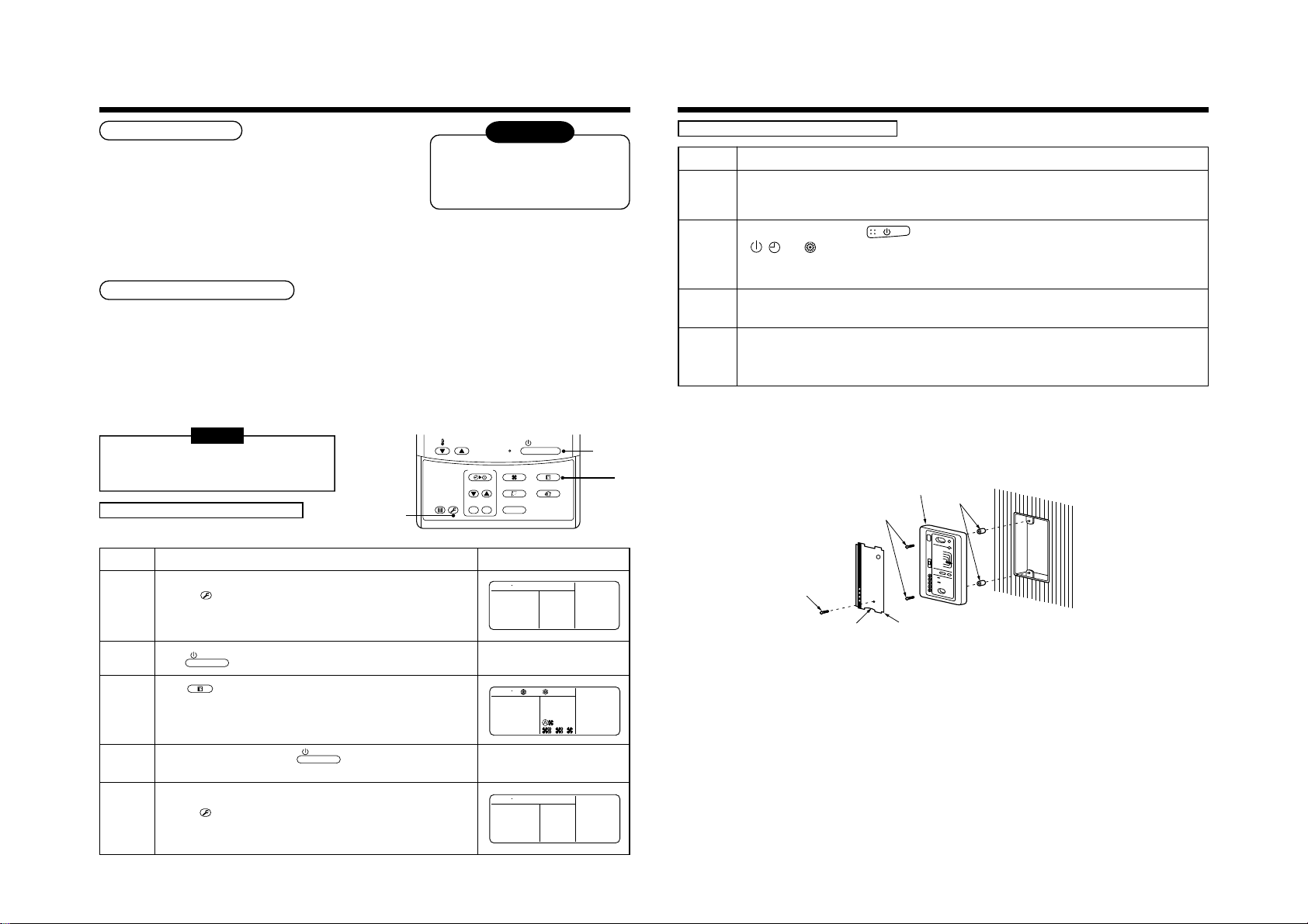
8
T
T
Receiver unit
M4 × 25 screw
(2 pieces)
Small screw
Spacer
Notch
Nameplate
TEST RUN
30
Before test operation
• Before turning on the power supply, carry out the following
procedures.
1) Using 500V-megger, check there is 1MΩ or more between the
terminal block of the power supply and the earth.
If 1MΩ or less is detected, do not run the unit.
2) Check that all the valves of the outdoor unit are fully opened.
• Never push the electromagnetic contactor to carry out a forced test operation.
(It is very dangerous because a protective device does not work.)
To protect the compressor at
startup. Ensure the power supply
is left on for 12 or more hours
before operation.
WARNING
How to execute test operation
• To carry out a fan operation in a single indoor unit, firstly turn off the power supply to the unit. Then short CN72
found on the P.C. board. Once completed turn the power to the unit back on and start the unit in FAN only mode.
Upon completion of the test do not forget to remove the short circuit on CN72.
• Using the remote controller, check the unit is in normal operation. For the operation procedure, refer to the
supplied Owner’s Manual. A forced test operation can be executed in the following procedure under the condition
of thermo.-OFF of room temperature.
In order to prevent the test operation from running continuously, the operation will cease after a period of
60 minutes. The unit will then return back to its original operation.
NOTE
Do not use a forced operation in cases other
than test operation because it applies an
excessive load onto the air conditioner.
In case of wired remote controller
Procedure
1, 5
Description
FILTER
RESET
TEMP.
TEST
TIMER SET
ON / OFF
2, 4
FAN
MODE
SWING/FIXTIME
VENT
UNITSET CL
3
In case of wireless remote controller
Procedure
Remove a small screw which fixes the nameplate of the receiver unit.
Remove the nameplate of the sensor section by inserting a minus screwdriver, etc into the notch at the bottom
1
of the plate, and set the Dip switch to [TEST RUN ON].
Execute a test operation with button on the wireless remote controller.
, , and LED flash during test operation.
•
2
• Under status of [TEST RUN ON], the temperature adjustment from the wireless remote controller is invalid.
Do not use this method in the operation other than test operation because the equipment is damaged.
Use either COOL or HEAT operation mode for a test operation.
3
* The outdoor unit does not operate approx. 3 minutes after power-ON and operation stop.
After the test operation finished, stop the air conditioner from the wireless remote controller, and return Dip
switch of the receiver section as before.
4
(A 60-minutes timer clearing function is attached to the receiver section in order to prevent a continuous test
operation.)
Description
1
2
3
4
5
TES
Keep the
[TEST] is displayed on the display part and the selection of the test mode is
permitted.
Push
Using
• Do not run the air conditioner in a mode other than [COOL] or [HEAT].
• The temperature controlling function will not work during the test operation.
• Fault detection will perform as usual.
After the test operation, push the
(Display part is the same as procedure
Push the
([TEST] disappears on the display part and the status returns to normal.)
button pushed down for 4 seconds or more.
ON / OFF
button.
MODE
button, select the operation mode, [COOL] or [HEAT].
ON / OFF
button to stop the operation.
1
)
TES
button to cancel (release from) the test operation mode.
TEST
Page 31

9
T
T
TROUBLESHOOTING
31
Confirmation and check
When a fault occurs in the air conditioner, the check
code and the indoor unit No. will appear on the display
part of the remote controller.
The check code will only be displayed while the unit is
in operation.
If the display disappears, operate the air conditioner
according to the following “Confirmation of error
history” for confirmation.
Confirmation of error history
When a fault occurs in the air conditioner, the error
history can be confirmed with the following procedure.
(The error history is stored in memory and can contain
up to 4 errors).
This history can be confirmed from either the operating
status or the stop status.
Procedure
SET
When pushing the
or more, the display similar to the one shown in the figure to the right
will appear.
If [Service Check] is displayed, the fault code will be stored in the
error history mode.
1
• 01 (Order of error history) is displayed in CODE No. window.
• Check Code is displayed in the CHECK window.
• The indoor unit address, where the fault has occurred will be
displayed in the UNIT No. window.
When pushing the
chronological order.
The numbers displayed within the CODE No. window can vary between 1 and 4. 1 being the most recent fault
2
and 4 being the oldest.
CAUTION
Do not push the
After confirmation, push the
3
TES
and
buttons simultaneously for 4 seconds
TEMP.
buttons, the error history stored within the memory will be displayed in
CL
button as this will erase all of the error history for that indoor unit.
TES
button. This will return the display back to its original mode.
2
3
Description
CODE No.
UNIT No.
R.C. No.
Check code Indoor unit No. in which
TEMP.
FILTER
RESET
TEST
an error occurred
TIMER SET
ON / OFF
FAN
MODE
SWING/FIXTIME
VENT
UNITSET CL
UNIT No.
R.C. No.
CODE No.
1
Check method
On the remote controller (Main remote controller, Central control remote controller) and the interface P.C. board of
the outdoor unit, a check display LCD (Remote controller) or 7-segment display (on the outdoor interface P.C.
board) operation is provided. Therefore the operation status can be known. Using this self-diagnosis function, a fault
and the location of this fault within the air conditioning system can be located, as shown in the table below.
Check code list
The following list shows each check code. Find the check contents from the list according to part to be checked.
• In case of a fault from the indoor remote controller: See “Main remote controller display” in the list.
• In case of a fault from the outdoor unit: See “Outdoor 7-segment display” in the list.
• In case of a fault from the indoor unit with a wireless remote controller:
See “Sensor block display of receiving unit” in the list.
Terminology
Check code Wireless remote controller
Main
remote
controller
display
E01 ——
E02 ——
E03 ——
E04 ——
E06 E06
— E07 —
E08 E08 Duplicated indoor addresses
E09 ——
E10 ——
E12 E12
E15 E15 —
E16 E16
E18 ——
E19 E19
E20 E20
E23 E23 —
E25 E25 —
E26 E26
E28 E28 Detected outdoor unit number
E31 E31
Outdoor 7-segment dis p lay
Auxiliary code
No. of indoor units in which sensor has
been normally received
01: Indoor/Outdoor communication
02: Communication between ou td oo r units
00: Capacity over
01 ~: No. of connected units
00: Header is nothing
02: Two or more header units
01: Outdoor of other line connected
02: Indoor of other line connected
No. of outdoor units which received signal
normally
01: IPDU1 error
02: IPDU2 error
03: IPDU1, 2 error
04: Fan IPDU error
05: IPDU + Fan IPDU error
06: IPDU2 + Fan IPDU error
07: All IPDU error
IPDU : Intelligent Power Drive Unit
¡ : Lighting,
ALT. : Flashing is alternately when there are two flashing LED.
SIM : Simultaneous flashing when there are two flashing LED.
Sensor block display
of receiving unit
Operation
Timer Ready Flash
ll
¤
ll
¤
ll
¤
ll
ll
ll
¤
¤
¤
¤
ll
ll
¤
ll
ll
ll
ll
ll
ll
ll
¤
¤
¤
ll
ll
ll
ll
¤
¤
ll
¤
¤
¤
¤
¤
¤
¤
: Flashing, l : Goes off
¤
Check code name Judging device
Communication error between indoor and remote
controller (Detected at remote controller side)
Remote controller transmission error Remote controller
Communication error between indoor and remote
controller (Detected at indoor side)
Communication c ir cu it error between indoor/outdoor
(Detected at indoor side)
Decrease of No. o f indoor units I/F
Communication c ir cu it error between indoor/outdoor
(Detected at outdoor side)
Duplicated indoor addresses Indoor / I/F
Duplicated main remote controllers Remote controller
Communication error between indoor MCU Indoor
Automatic address start error I/F
Indoor is nothing during automatic addressing I/F
Capacity over / No. of connected indoor units I/F
Communication error between indoor units Indoor
Outdoor header units quantity error I/F
Other line connected du ring automati c ad dress I/F
Sending error in communication between outdoor units I/F
Duplicated follower outdoor addresses I/F
Decrease of No. o f c onne cted outdoor units I/F
Follower outdoor un it error I/F
IPDU communication error I/F
Remote controller
Indoor
Indoor
I/F
Page 32

9
y
g
TROUBLESHOOTING
32
Main
remote
controller
display
F01 ——
F02 ——
F03 ——
F04 F04 —
F05 F05 —
F06 F06 —
F07 F07 —
F08 F08 —
F10 ——
F12 F12 —
F13 F13
F15 F15 —
F16 F16 —
F23 F23 —
F24 F24 —
F29 ——
F31 F31 —
H01 H01
H02 H02
H03 H03
H04 H04 —
H06 H06 —
H07 H07 —
H08 H08
H14 H14
H16 H16
L03 ——
L04 L04 —
L05 ——
L06 L06 No. of indoor units with priority
L07 ——
L08 L08 —
L09 ——
L10 L10 —
L20 L20 —
L28 L28 —
L29 L29
L30 L30 Detected indoor address
— L31 ——Extended I/C error I/F
Check code Wireless remote controller
Outdoor 7-segment dis p lay
Auxiliary code
01: Comp. 1 side
02: Comp. 2 side
01: Comp. 1 side
02: Comp. 2 side
01: Comp. 1 side
02: Comp. 2 side
01: Comp. 1 side
02: Comp. 2 side
01: TK1 sensor error
02: TK2 sensor error
03: TK3 sensor error
04: TK4 sensor error
01: TK1 oil circuit system error
02: TK2 oil circuit syst e m er ror
03: TK3 oil circuit system error
04: TK4 oil circuit system error
01: IPDU1 error
02: IPDU2 error
03: IPDU3 error
04: Fan IPDU error
05: IPDU1 + Fan IPDU error
06: IPDU2 + Fan IPDU error
07: All IPDU error
—
Sensor block display
of receiving unit
Operation
Timer Ready Flash
¤¤
¤¤
¤¤
¤¤
¤¤
¤¤
¤¤
¤¤
¤¤
¤¤
¤¤
¤¤
¤¤
¤¤
¤¤
¤¤
¤¤
l
¤
l
¤
l
¤
l
¤
l
¤
l
¤
l
¤
l
¤
l
¤
l
¤
¡
¤
l
¤
l
¤
l
¤
l
¤
l
¤
¡
¤
¡
¤
¡
¤
¡
¤
¡
¤
Check code name Judging device
ALT Indoor TCJ sensor error Indoor
l
ALT Indoor TC2 sensor error Indoor
l
ALT Indoor TC1 sensor error Indoor
l
ALT TD1 sensor error I/F
¡
ALT TD2 sensor error I/F
¡
ALT TE1 sensor error I/F
¡
ALT TL sensor error I/F
¡
ALT TO sensor error I/F
¡
ALT Indoor TA sensor error Indoor
l
ALT TS1 sensor error I/F
¡
ALT TH sensor error IPDU
¡
ALT Outdoor temp . sensor miscablin g (TE , TL) I/F
¡
ALT Outdoor pressure sensor misca blin g (Pd, Ps) I/F
¡
ALT Ps sensor error I/F
¡
ALT Pd sensor error I/F
¡
SIM Indoor other error Indoor
l
SIM Indoor EEPROM error I/F
¡
l
l
l
l
l
l
l
l
l
¤
¤
¤
¤
¤
¤
¤
¤
¤
¤
¤
¤
Compressor break down IPDU
Magnet switch e rr or
Overcurrent re lay operation
Compressor tro uble ( loc k)
Current detect circuit system error IPDU
Comp 1 case thermo op era tio n I/F
Low pressure protec tive oper atio n I/F
Oil level down de tec t iv e pro t ec tio n I/F
Oil level detect ive te mp sen sor error I/F
Comp 2 case thermo op era tio n I/F
Oil level dete ct iv e cir c u it err o r
Magnet switch e rr or
Overcurrent re lay operation
SIM Indoor center unit duplicated Indoor
SIM Outdoor l ine ad d res s duplicated I/F
Duplicated indo or un it s with priority
SIM
(Displayed in in do or u ni t w ith pr ior ity)
Duplicated indo or un it s with priority
SIM
(Displayed in un it other than indoor unit with pri ori ty )
SIM Group line in indi vid ua l ind oor unit Indoor
SIM Indoor group/Address unset Indoor, I/F
SIM Indoor capacity unset Indoor
SIM Outdoor capa city unset I/F
SIM Duplicated central control addresses Indoor
SIM Over No. of connec ted ou tdoo r un i ts I/F
SIM No. of IPDU error I/F
SIM Indoor outside interlock Indoor
MG-SW
Overcurrent re la
IPDU
I/F
MG-SW
Overcurrent re la y
I/F
I/F
Main
remote
controller
display
P01 ——
P03 P03 —
P04 P04
P05 P05
P07 P07
P10 P10 Detected indoor address
P12 ——
P13 P13 —
P15 P15
P17 P17 —
P19 P19 Detected outdoor unit number
P20 P20 —
P22 P22
P26 P26
P29 P29
P31 P31 —
Check code Wireless remote controller
Outdoor 7-segment dis p lay
Auxiliary code
01: Comp. 1 side
02: Comp. 2 side
01: Phase-mi ssi ng detectio n
02: Phase error
01: Comp. 1 side
02: Comp. 2 side
01: TS condition
02: TD condition
0[: IGBT short
1[: Fan motor position detective circuit error
3[: Fan motor trouble
: TH sensor temp. error
C
[
(Heat sink overheat)
D[: TH sensor error
: Vdc output error
E
[
01: Comp. 1 side
02: Comp. 2 side
01: Comp. 1 side
02: Comp. 2 side
Sensor block display
of receiving unit
Operation
Timer Ready Flash
l
¤¤
l
¤
l
¤
l
¤
l
¤
l
¤¤
l
¤¤
l
¤¤
l
¤
l
¤
l
¤
l
¤
l
¤
l
¤
l
¤
l
¤
Check code name Judging device
ALT Indoor fan motor error Indoor
ALT Discharge temp. TD1 error I/F
¤
ALT High-pressure SW system operation IPDU
¤
ALT Phase- mis sin g det ec ti o n /P ha se e rro r I/F
¤
ALT Heat sink overheat error IPDU, I/F
¤
ALT Indoor overflow error Indoor
ALT Indoor fan motor error Indoor
ALT Outdoor liqu id back detection error I/F
ALT Gas leak detec tion I/F
¤
ALT Discharge temp. TD2 error I/F
¤
ALT 4-way valve inverse error I/F
¤
ALT High-pre ss ure pr o te ct ive operation I/F
¤
ALT Outdoor fan IPDU error IPDU
¤
ALT G-TR short protection error IPDU
¤
ALT Comp position detective circuit system error IPDU
¤
ALT Other indoor u ni t e rror (G roup te r mina l u nit e rror ) Indoor
¤
Error detected by TCC-LINK central control device
Central
control
device
indication
C05 —— —Sending error in TCC-LINK c entr al c ontr o l device TCC-LINK
C06 —— —Receiving error in TCC-LINK central control device TCC-LINK
C12 —— —
P30
Check code Wireless remote controller
Outdoor 7-segment dis p lay
Auxiliary code
Differs according to error contents of unit with occurrence of alarm Group control branching unit error
—— (L20 is displayed.) Duplicated central control addresses
Sensor block display
of receiving unit
Operation
Timer Ready Flash
Batch alarm of
interface
Check code name Judging dev ice
eneral-purpose equipment control
General-purpo se eq u ip me nt
Terminology
TCC-LINK : TOSHIBA Carrier Communication Link.
I/F
TCC-LINK
Page 33

9
FILTER
RESET
FILTER
RESET
Strap to
prevent falling
Air filter
Push
1
Insert
2
Insert in the flap sagging
down the center downward.
TROUBLESHOOTING
10
MAINTENANCE
33
New check code
1. Difference between the new check code and the current system
The displaying method of the check code will change from this model onwards.
New check code
Used characters
Characteristics of code classification
Block display
Display on wired remote controller
• [ ] goes on.
• [UNIT No.] + Check code + Operation lamp (Green) flash
Display on sensor part of wireless remote controller
• Block display will show a combination of
] [ ] [ ] symbols.
[
Display on 7-segment in outdoor unit
• Unit No. and check code are displayed.
• In case of error the auxiliary code, check code and sub-code
are displayed alternately.
2. Special mention
• When the air conditioner stops and the error is cleared, the check code display on the remote controller will also
disappear.
However, if the error continues after the unit has been stopped, the check code will immediately be displayed
when the unit is restarted.
Alphabet + Decimal notation, 2 digits
Many classification of communication/incorrect setup system
Communication/Incorrect setup (4-ways), Indoor protection, Outdoor protection,
Sensor, Compressor protection, etc.
→
Display
A
Unused
C
Central control system error
E
Communication system error
F
Each sensor error (Failure)
H
Compressor protective system error
J
Unused
L
Setup error, Other errors
P
Protective device operation
Classification
Prior to maintenance, ensure the power supply is turned off.
CAUTION
Do not handle the buttons with wet hands as this will cause the risk of electric shock.
Daily maintenance
Cleaning of air filter
1
If is displayed on the remote controller, maintenance
to the air filter is required.
2
Clogging of the air filter decreases cooling/heating efficiency.
3
After cleaning, push the
display disappears.
.
[4-way Air Discharge Cassette Type]
1
Open the air inlet grille.
• Slide the air inlet grille buttons to detach the air
inlet grille from the main ceiling panel. Lower the
grille slowly while holding.
2
Take out the air filter.
• Push the extrusion of the air filter away from the
grille and remove.
3
Cleaning with water or vacuum cleaner
• If dirt is heavy, clean the air filter using tepid water
with a neutral detergent or just water.
• After cleaning with water, dry the air filter
sufficiently in a shaded place.
4
5
6
2
1
Mount the air filter.
Close the air inlet grille.
• Close the air inlet grille, slide the button to locate
into the ceiling panel fixing securely.
Push the
• display disappears.
3
1,
2
3
.
TEMP.
FILTER
TEST
RESET
Air inlet grille
TIMER SET
CODE No.
ON / OFF
FAN
MODE
SWING/FIXTIME
VENT
UNITSET CL
5
Air inlet grille
Button
Cleaning of air outlet flap
The air outlet flap can be removed to clean if necessary.
1
Remove the air outlet flap.
• Holding both ends of the air outlet flap, remove it by sagging the center downwards.
2
Clean the air outlet flap with water.
• If dirt is heavy, clean the air outlet flap using tepid water with neutral detergent or just water.
3
Mount the air outlet flap.
• First push in the one side, and insert the opposite side by sagging
the center downwards.
Be careful to insert the flap in the correct direction.
Insert the flap with the printed mark facing upwards, and
the arrow on the flap pointing in the outward direction.
Button
1
2
3
Page 34

4. REFRIGERATING CYCLE DIAGRAM
Gas sideLiquid side
Strainer
Pulse Motor
Valve (PMV)
Sensor
(TC2)
Capillary tube
Strainer
Sensor
(TCJ)
Air heat exchanger
at indoor side
Fan
Sensor
(TA)
M
Sensor
(TC1)
Fan motor
Functional part name
Pulse Motor Valve PMV
Temp. sensor 1. TA
2. TC1
3. TC2
4. TCJ
Functional outline
(Connector CN082 (6P): Blue)
1) Controls super heat in cooling operation
2) Controls under cool in heating operation
3) Recovers refrigerant oil in cooling operation
4) Recovers refrigerant oil in heating operation
(Connector CN104 (2P): Yellow)
1) Detects indoor suction temperature
(Connector CN100 (3P): Brown)
1) Controls PMV super heat in cooling operation
(Connector CN101 (2P): Black)
1) Controls PMV under cool in heating operation
(Connector CN102 (2P): Red)
1) Controls PMV super heat in cooling operation
34
Page 35

5. CONTROL OUTLINE
5-1. Control Specifications
No.
1
Power supply
is reset.
2 Operation
select
Outline of specifications
1. Distinction of outdoor unit
When the power supply is reset, the outdoor units are
distinguished, and control is exchanged according to the
distinctive results.
2. Check code clear
When the power supply is reset, the check code is also reset
once. If an abnormal status which the check code appears
after Start/Stop button of the remote controller has been
pushed continues, the check code is displayed again on the
remote controller.
1. Based upon the operation select command from the remote
controller or central controller, the operation mode is selected.
Remote controller
command
STOP
FAN
COOL
DRY
HEAT
COOL/HEAT AUTO
Heating operation is automatically selected with difference
between setup temperature and room temperature.
Control outline
Stops air conditioner.
Fan operation
Cooling operation
Dry operation
Heating operation
COOL/HEAT AUTO operation
RemarksItem
3 1. Adjustment range, set temperature on remote controller (°C)
Room temp.
control
Wired type
Wireless type
2. From the item code 06, the setup temperature in heating
operation can be corrected.
Setup data
Setup temp. correction
Setup at shipment
Setup data 2
4 Automatic
capacity
control
Air volume
5 1. By the command from the remote controller, “HIGH ”,
control
1. Based upon difference between Ta and Ts, the operation
frequency is indicated to the outdoor unit.
“MED
executed.
2. While air speed is in AUTO mode, the air speed is changed
according to the difference between Ta and Ts.
”, or “LOW ” and “AUTO ” operation is
All cooling
18 to 29°C
18 to 30°C
0246
+0°C +2°C +4°C +6°C
All heating
18 to 29°C
16 to 30°C
Heating suction temperature
shift
TS: Set temperature
Ta: Room temperature
35
Page 36

No.
Item
Outline of specifications
Remarks
6
Prevention of
cold air
discharge
7 Freeze
prevention
control (Low
temp. release)
1. In all heating operation, the upper limit of the fan tap is set by
one with higher temperature of TC2 sensor and TCJ sensor.
• When B zone has continued for 6 minutes, the operation
shifts to C zone.
• In defrost time, the control point is set to +6°C.
(˚C)
32
30
28
26
D
C
A zone: OFF
B zone:
Over 26˚C, below 28˚C, ULTRA LOW
C zone:
E
Over 28˚C, below 30˚C, LOW
D zone:
Over 30˚C, below 32˚C, MED
E zone: HIGH
20
16
B
A
1. In all cooling operation, the air conditioner operates as described below based upon temp. detected by TC1, TC2 and
TCJ sensors.
To prevent the heat exchanger from freezing, the operation
stops.
• When “J” zone is detected for 5 minutes, the command
frequency becomes “S0” to the outdoor unit.
• In “K” zone, the timer count is interrupted, and held.
• When “1 ” zone is detected, the timer is cleared and the
operation returns to the normal operation.
• When the command frequency became S0 with continua-
tion of “J” zone, operation of the the indoor fan in LOW
mode until it reaches the “1 ” zone.
It is reset when the following conditions are satisfied.
• In D and E zones, priority
is given to remote controller air speed setup.
• In A “
” is displayed.
Reset conditions
1) TC1
>
12°C and TC2 > 12°C and TCJ > 12°C
2) 30 minutes passed after stop.
(˚C)
P1
Q1
I
K
J
a
P1
Q1
TC1
10°C (5°C)
0°C
TC2, TCJ
–10°C
–14°C
2. In all cooling operation, the air conditioner operates as
described below based upon temp. detected by TC2 and TCJ
sensors.
• When “M” zone is detected for 45 minutes, the command
frequency becomes “S0” to the outdoor unit.
• In “N” zone, the timer count is interrupted and held.
• When shifting to “M” zone again, the timer count restarts
and continues.
• If “L” zone is detected, the timer is cleared and the opera-
tion returns to normal operation.
Reset conditions
1) TC1
>
12°C and TC2 > 12°C and TCJ > 12°C
2) 30 minutes passed after stop.
(˚C)
P2
Q2
L
N
M
P2
Q2
TC2, TCJ
5°C
–2.0°C
( ) value:
When the power supply is
turned on, the Forced
thermo becomes OFF if the
temperature is less than this
indicated temperature.
∗ In a Model without TC2,
TC2 is not judged.
36
Page 37

No.
Item
Outline of specifications
Remarks
8
Recovery control
for cooling
refrigerant and oil
9
Recovery control
for heating
refrigerant and oil
10
Short intermittent
operation
compensation
control
1. The indoor unit which stops operation, thermostat is OFF,
or operates in FAN mode opens PMV of the indoor unit by
the specified opening degree when cooling refrigerant or oil
recovery signal is received from the outdoor unit.
2. Drain pump of Compact 4-way Air Discharge Cassette type
operates during recovery control mode.
The indoor unit which stops operation, thermostat is OFF, or
operates in FAN mode performs the following controls when
the heating refrigerant/Oil recovery signal is received from the
outdoor unit.
1. Opens PMV of the indoor unit by the specified opening
degree.
2. Stops the fan.
3. Compact 4-way Air Discharge Cassette type air conditioner
rotates the indoor fan with Ultra Low Fan operation for
approx. 1 minute after recovery control.
4. After recovery control, drain pump of Compact 4-way Air
Discharge Cassette type will operate.
1. For 5 minutes after the operation has started, the operation
is continued even if entering thermostat-OFF condition.
2. However, if the thermostat has been turned off by changing
the set up temp., the thermostat is OFF with even the
above condition. The protective control has priority.
• Recovery operation is
usually executed every 2
hours.
• In the indoor unit which
thermostat is OFF, or
operates in FAN mode,
“
” lamp goes on.
• Recovery operation is
usually executed every
1 hour.
(In this time the flap
directs upward)
11
Drain pump
control
12 Elimination of
remaining heat
13 Auto flap control 1. When the flap signal has been received from the remote
14 Filter sign display
(None in wireless
type)
∗ Provided in the
separately laid
type
TCB-AX21E.
1. During “COOL” operation (including DRY operation), the
drain pump operates.
2. While the drain pump operates, if the float switch works,
the drain pump continues operation and a check code is
displayed.
3. While the drain pump stops, if the float switch works, turn
off the capacity demand command, stop the operation, and
operate the drain pump. If the float switch continues
operating for approx. 5 minutes, the operation stops and
the check code is displayed.
1. When the air conditioner stops in the “HEAT” mode, drive
the indoor fan with “LOW” mode for approx. 30 seconds.
controller, the louver operates if the indoor fan is operating.
2. In Compact 4-way Air Discharge Cassette type, the
discharge flap automatically directs upward if the operation
stops.
3. In Compact 4-way Air Discharge Cassette type, the
discharge flap directs upward if the heating operation is
being prepared.
1. The operation time of the indoor fan is integrated and
stored in memory, and the filter exchange signal is sent to
the remote controller to display on the remote controller
LCD after the specified time.
2. When the filter reset signal is received form the remote
controller, time of the integrated timer is cleared. In this
time, if the specified time has passed, the measured time is
reset and LCD display disappears.
Check code [P10]
37
Page 38

No.
Item
Outline of specifications
Remarks
15
“ ” and “ ”
display
(Operation and
heating stand-by)
<Operation standby> .......... Display on remote controller
1. •“P05” is one of displays of power wire missing.
•“P05” of power cable is detected.
•“COOL/DRY” operation cannot be performed because the
other indoor unit is under “HEAT” operation.
•“HEAT” operation cannot be performed because COOL
priority is set (Outdoor I/F P.C. board SW11 1-bit is ON)
and the other indoor unit is under “COOL/DRY” operation.
•“FAN” operation cannot be performed because the system
performs “Heat oil/Refrigerant recovery” operation.
• There is a unit in which indoor overflow “P10” is detected.
• There is a unit in which interlock alarm “P23” is detected.
2. The above indoor units unavailable to operate waits under
condition of thermostat OFF.
<HEAT standby> .................. Display on remote controller
1. • During HEAT operation, the fan rotates with lower air speed
than one specified in order to prevent discharge of cold
draft or stops. (including case that defrost operation is
being performed)
•“HEAT” operation cannot be performed because COOL
priority is set (Outdoor I/F P.C. board SW11 bit 1 is ON) and
the other indoor unit is under “COOL/DRY” operation.
2. “HEAT standby” is displayed until the above conditions are
released.
•“ ” goes on.
•“
” goes on.
16 Selection of
central control
mode
1. The contents which can be changed on the remote controller
at indoor unit side can be selected by setup at the central
controller side.
2. In case of operation from TCC-LINK central controller
(TCB-SC642 TLE2, etc.)
[Central control mode 1] : Cannot operate
[Central control mode 2] :
Cannot operate, stop, select mode, set up temp.
[Central control mode 3] :
Cannot select mode, set up temp.
[Central control mode 4] : Cannot select mode
3. RBC-AMT31E (Wired remote controller)
While mode is the central control mode, “
lights on the display part of the remote controller.
CENTRAL”
If operation is performed
from the remote control
“CENTRAL CONTROL”
mode, the status is
notified with receiving
sound.
38
Page 39

6. APPLIED CONTROL
6-1. Setup of Selecting Function in Indoor Unit
(Be sure to Execute Setup by a Wired Remote Controller)
<Procedure> Execute the setup operation while the unit stops.
TEMP.
ON / OFF
3
TIMER SET
FAN
MODE
5
6
FIL TER
RESET
TEST
SWING/FIXTIME
UNITSET CL
VENT
1
1
SET, CL
Push
The firstly displayed unit No. indicates the header indoor unit address in the group control.
In this time, the fan of the selected indoor unit is turned on.
, and
TEST
buttons simultaneously for 4 seconds or more.
4
2
2
Every pushing
displayed. In this time, the fan of the selected indoor unit only is turned on.
3
Specify the item code (DN) using the setup temperature and buttons.
4
Select the setup data using the timer time and buttons.
(When selecting the DN code to “33”, change the temperature indication of the unit from “°C”
to “°F” on the remote controller.)
5
6
SET
Push
• To change the selected indoor unit, return to procedure 2 .
• To change the item to be set up, return to procedure 3 .
Pushing
button. (OK if display goes on.)
TEST
UNIT
button, the indoor unit numbers in the group control are successively
button returns the status to normal stop status.
39
Page 40

Table: Function selecting item numbers (DN)
(Items necessary to perform the applied control at the local site are described.)
DN
01
Filter display delay timer
02
Dirty state of filter
03
Central control address
04
Specific indoor unit priority
06
Heating temp shift
0d
Existence of [AUTO] mode
0E
Follows operation mode of
the header unit
0F
Cooling only
10
Type
Item
Description
0000 : None 0001 : 150H
0002 : 2500H 0003 :5000H
0004 : 10000H
0000 : Standard
0001 : High degree of dirt (Half of standard time)
0001 : No.1 unit to 0064 : No.64 unit
0099 : Unfixed
0000 : No pr ior ity 0001 :Priority
0000 : No shift 0001 : +1°C
0002 : +2°C to 0010 : +10°C
(Up to +6 recommended)
0000 : Provided
0001 : Not provided (Automatic selection from connected outdoor unit)
0000 : Does not follow
0001 : Follows
0000 : Heat pump
0001 : Cooling only (No display of [AUTO] [HEAT])
0014: Compact 4-way Air Discharge Cassette
At shipment
0002 : 2500H
0000 : Standard
0099 : Unfixed
0000 : No priority
0002 : +2°C
(Floor type 0000: 0°C)
0001 : Not provided
0000 : Not provided
0000 : Heat pump
0014:
Compact 4-way A/D only
11
Indoor unit capacity
12
Line address
13
Indoor unit address
14
Group address
1E
Temp difference of [AUTO]
mode selection COOL →
HEAT, HEAT → COOL
28
Automatic restart of power
failure
2A
Selection of option/error
input (CN70)
2E
HA terminal (CN61) select
31
Ventilating fan control
32
TA sensor selection
33
Temperature unit select
5d
High ceiling selection
(Air volume selection)
0000 : Unfixed 0001 to 0034
0001 : No.1 unit to 0030 :No.30 unit
0001 : No.1 unit to 0064 :No.64 unit
0000 : Individual 0001 :Header unit of group
0002 : Follower unit of group
0000 : 0 deg t o 0010 :10 deg
(For setup temperature, reversal of COOL/HEAT by ± (Data value)/2)
0000 : None 0001 :Restart
0000 : Filter input 0001 : Alarm input (Air washer, etc.)
0002 : None
0000 : Usual 0001 :Leaving-ON prevention control
0002 : Fire alarm input
0000 : Unavailable 0001 :Available
0000 : Body TA sensor 0001 :Remote controller sensor
0000 : °C (at factory shipment)
0001 : °F
[Compact 4-way Air Discharge Cassette type]
0000 : AP007 to AP012; Below 2.7m
AP015; Below 2.9m
AP018; Below 3.2m
0002 : AP015; Below 3.2m
AP018; Below 3.4m
0003 : AP015, AP018; Below 3.5m
According to capacity type
0099 : Unfixed
0099 : Unfixed
0099 : Unfixed
0003 : 3 deg
(Ts±1.5)
0000 : None
0002 : None
0000 : Usual
(HA terminal)
0000 : Unavailable
0000 : Body TA sensor
0000 : °C
0000 : Standard
60
Timer set
(Wired remote controller)
0000 : Available (Operable)
0001 : Unavailable (Operation prohibited)
40
0000 : Available
Page 41

TYPE
Indoor unit capacity
Item code [10]
Setup
data
0014
Compact 4-way Air Discharge Cassette
Type
Abbreviated
Model name
MMU-AP XXX MH
Item code [11]
Setup data
0001
0003
0005
0007
0009
Model
007
009
012
015
018
6-2. Applied Control in Indoor Unit
n Remote location ON/OFF control box (TCB-IFCB-4E)
[Wiring and setup]
• Use the exclusive connector for connection with the indoor control P.C. board.
• In a group control, the system can operate when connecting with any indoor unit (Control P.C. board) in the
group. However when taking out the operation/error signal from the other unit, it is necessary to take out from
each unit individually.
(1) Control items
1) Start/Stop input signal : Operation start/stop in unit
2) Operation signal : Output during normal operation
3) Error signal : Output during alarm
(Serial communication error or indoor/outdoor protective device) operation
(2) Wiring diagram using remote control interface (TCB-IFCB-4E)
Input IFCB-4E : No voltage ON/OFF serial signal
Output No voltage contact f or operation, error display
Contact capacity: Belo w Max. AC240V 0.5A
Indoor control P.C. board
Start/Stop input
COM (GND)
Remote controller prohibition/clear input
Operation signal output
COM (+12V)
Error signal output
1
2
3
4
5
6
CN61
T10
(YEL)
Remote location ON/OFF control box
(TCB-IFCB-4E)
1
2
3
4
CN06
1
2
3
4
5
6
CN13
ON/OFF serial
signal input
COM
Operation signal output
Power supply 220–240V,
41
~
Error signal output
50Hz
Page 42

n Ventilating fan control from remote controller
[Function]
• The start/stop operation can be operated from the wired remote controller when air to air heat exchanger or
ventilating f an is installed in the system.
• The fan can be operated even if the indoor unit is not operating.
• Use a fan which can receive the no-voltage A contact as an outside input signal.
• In a group control, the units are collectively operated and they can not be individually operated.
(1) Operation
Handle a wired remote controller in the following procedure.
∗ Use the wired remote controller during stop of the system.
∗ Be sure to set up the wired remote controller to the header unit. (Same in group control)
∗ In a group control, if the wired remote controller is set up to the header unit, both header and follower units
are simultaneously operable .
1
Push concurrently
The unit No. displayed firstly indicates the header indoor unit address in the group control.
In this time, the fan of the selected indoor unit turns on.
2
Every pushing
SET
+ CL +
UNIT
button, the indoor unit numbers in group control are displayed succes-
TEST
buttons for 4 seconds or more.
sively.
In this time, the fan of the selected indoor unit only turns on.
3
Using the setup temp or button, specify the item code !.
4
Using the timer time or button, select the setup data. (At shipment: )
The setup data are as follows:
Setup data
5
SET
Push
• To change the selected indoor unit, go to the procedure 2 ).
• To change the item to be set up, go to the procedure 3 ).
button. (OK if display goes on.)
Handling of operation of air to air heat exchanger or ventilating fan
Unavailable (At shipment)
Available
6
Pushing
(2) Wiring
CN32
FAN DRIVE
(2P WHI)
Indoor control
P.C. board
Note) Determine the cable length between the
TEST
returns the status to the usual stop status.
Relay (DC12V, procured locally)
121
2
indoor control P.C. board and the relay within 2m.
Outside control
input of fan
To terminal
42
Compact 4-way Air Discharge Cassette type
4-way Air Discharge Cassette type
1-way Air Discharge Cassette type (2 series)
Concealed Duct Standard type
Slim Duct type
Under Ceiling type
High Wall type
Corresponds up to a relay in which rated current of the
operation coil is approx. 75mA
Other type models:
Correspond up to a relay in which rated current of the
operation coil is approx. 16mA (Does not correspond
to a terminal block type relay on the market.)
model :
Page 43

n Leaving-ON prevention control
[Function]
• This function controls the indoor units individually . It is connected with cable to the control P.C. board of the
indoor unit.
• In a group control, it is connected with cable to the indoor unit (Control P.C. board), and the item code - is
set to the connected indoor unit.
• It is used when the start operation from outside if unnecessary but the stop operation is necessary.
• Using a card switch box, card lock, etc, the forgotten-OFF of the indoor unit can be protected.
• When inserting a card, start/stop operation from the remote controller is allowed.
• When taking out a card, the system stops if the indoor unit is operating and start/stop operation from the
remote controller is forbidden.
(1) Control items
1) Outside contact ON : The start/stop operation from the remote controller is allowed.
(Status that card is inserted in the card switch box)
2) Outside contact OFF : If the indoor unit is operating, it is stopped forcedly.
(Start/Stop prohibited to remote controller)
(Status that card is taken out from the card switch box)
∗ When the card switch box does not perform the above contact operation, convert it using a relay with b
contact.
(2) Operation
Handle the wired remote controller switch in the f ollowing procedure.
∗ Use the wired remote controller switch during stop of the system.
1
Push concurrently
2
Using the setup temp or button, specify the item code - .
3
Using the timer time or button, set to the setup data.
Push
Push
SET
button.
TEST
button. (The status returns to the usual stop status.)
4
5
SET
+ CL +
(3) Wiring
CN61
T10
2
(YEL)
4
6
Indoor control P.C. board
Note) Determine the cable length between the indoor control P.C. board and the relay within 2m.
TEST
buttons for 4 seconds or more.
Relay (procured locally)
121
343
565
Power supply
Outside contact (Card switch box, etc: Procured locally)
n Power peak-cut from indoor unit
When the relay is turned on, a forced thermostat-OFF operation starts.
* In the figure, the contact indicates
a status that the card is taken out.
• Wiring example
CN73
EXCT
(2P plug: RED)
Indoor control P.C. board
121
2
Relay (procured locally)
Note) Determine the cable length between the indoor or
outdoor control P.C. board and the relay within 2m.
Relay coil signal
43
Page 44

7. TROUBLESHOOTING
7-1. Troub leshooting Summary
1. Before troubleshooting
1) Applied models
S-MMS Multi type models
Q
Indoor unit: MMX-APXXX,
Outdoor unit: MMY-MAPXXXHT8, MMY-MAPXXXT7
Super Heat Recovery Multi type models
R
Indoor unit: MMX-APXXX,
Outdoor unit: MMY-MAPXXXFT8
Mini-S-MMS Multi type models
S
Indoor unit: MMX-APXXX,
Outdoor unit: MCY-MAPXXXHT, MCY-MAPXXXHT2D
2) Required tools / measuring devices
• Screwdrivers (Philips, Minus), spanner, radio pinchers, nipper, push pin for reset switch, etc.
• Tester, thermometer , pressure gauge, etc.
3) Confirmation before check (The following items are not troubles.)
No.
1
Compressor does not operate.
2
Indoor fan does not work.
3
Outdoor fan does not rotate, or
fan speed changes.
Indoor fan does not stop.
4
Start/stop operation on remote
5
controller is unavailable.
6
Operation
——
Check items
• Is not delayed for 3 minutes? (3 minutes after compressor-OFF)
• Is not thermostat OFF?
• Is not the fan operating or timer?
• Is not the system initially communicating?
Heating operation cannot be performed under condition of outside tempera-
ture 21°C or higher.
Cooling operation cannot be performed under condition of outside tempera-
ture –5°C or lower.
• Is not the cold draft prevention being controlled in heating operation?
• Is not low cooling operation being controlled?
• Is not a defrost operation being performed?
• Is not after-heat elimination operation being controlled after heating operation?
• Is not auxiliary unit or remote control being operated?
• Is connecting wire of indoor unit or remote controller correct?
2. Troubleshooting procedure
When a trouble occurred, advance the check operation in the following procedure.
Trouble
Check the check display
on the interface P.C. board
of the outdoor unit.
Check position or part
in which trouble occurred.
NOTE) While a check operation is performed, a malfunction of the microprocessor may be caused due to
condition of the power supply or the external noise. If there is any noise source, change wires of the
remote controller and signal wires to shield wires.
44
Page 45

7-2. Check Method
On the remote controller (Main remote controller, Centr al control remote controller) and the interface P.C. board
of the outdoor unit, a check display LCD (Remote controller) or 7-segment display (on the outdoor interface P.C.
board) to display the operation is provided. Therefore the operation status can be known. Using this self-diagnosis function, a trouble or position with trouble of the air conditioner can be found as shown in the table below.
Check code list
The following list shows each check code. Find the check contents from the list according to part to be checked.
• In case of check from indoor remote controller: See “Main remote controller display” in the list.
• In case of check from outdoor unit: See “Outdoor 7-segment display” in the list.
• In case of check from indoor unit with wireless remote controller: See “Sensor block display of receiving unit”
in the list.
IPDU: Intelligent Power Drive Unit
¡ : Lighting, ¤ : Flashing, l : Goes off
ALT.: Flashing is alternately when there are two flashing LED.
SIM: Simultaneous flashing when there are tw o flashing LED
Check code Wireless remote controlle r
Main
remote
controller
display
E01 ——
E02 ——
E03 ——
E04 ——
E06 E06
— E07 —
E08 E08 Duplicated indoor ad dre sse s
E09 ——
E10 ——
E12 E12
E15 E15 —
E16 E16
E18 ——
E19 E19
E20 E20
E23 E23 —
E25 E25 —
E26 E26
E28 E28 Detected outdoor un it nu mber
E31 E31
Outdoor 7-segment display
Auxiliary code
No. of indoor uni ts in w h ich s enso r h as
been normally received
01: Indoor/Outdoor communication
02: Communication between out door un its
00: Capacity over
01 ~: No. of connected units
00: Header is nothing
02: Two or more header units
01: Outdoor of other line connected
02: Indoor of other line con nected
No. of outdoor un its w hich recei ved sign al
normally
01: IPDU1 error
02: IPDU2 error
03: IPDU1, 2 error
04: Fan IPDU error
05: IPDU + Fan IPDU error
06: IPDU2 + Fan IPDU error
07: All IPDU error
Sensor block display
of receiving unit
Timer Ready Flash
Operation
ll
¤
ll
¤
ll
¤
ll
ll
ll
ll
¤
ll
¤
ll
¤
ll
¤
ll
ll
ll
¤
ll
ll
ll
ll
ll
ll
ll
¤
¤
¤
¤
¤
¤
¤
¤
¤
¤
¤
¤
Check code name Judging device
Communication error betw ee n indoor and re mote
controller (Detec ted at re mote contr ol ler si de)
Remote controller transmission error Remote controller
Communication error betw ee n indoor and re mote
controller (Detecte d at indo or si de)
Communication circu it err or betw ee n
indoor/outdoor (D ete cted a t indoor s ide )
Decrease of No. of indoor unit s I/F
Communication circu it err or betw ee n
indoor/outdoor (D ete cted a t outd oor side )
Duplicated indoor ad dre sse s Indoor / I/F
Duplicated main remote controllers Remote controller
Communication error betw ee n ind oor M C U Indoor
Automatic addres s s tar t er ror I/F
Indoor is noth ing d ur ing au to ma tic addr es sing I/F
Capacity over / No . o f conn ected in door u nit s I/F
Communication error betw een ind oor un its Indoor
Outdoor header uni ts quant ity error I/F
Other line connected during auto matic addres s I/F
Sending error in commun icat ion be tw een outdoor
units
Duplicated follow er outd oor add res ses I/F
Decrease of No. of connected out door uni ts I/F
Follower outdoor unit error I/F
IPDU communication error I/F
Remote controller
Indoor
Indoor
I/F
I/F
45
Page 46

Check code Wireless remote controlle r
y
Main
remote
controller
display
F01 ——
F02 ——
F03 ——
F04 F04 —
F05 F05 —
F06 F06 —
F07 F07 —
F08 F08 —
F10 ——
F12 F12 —
F13 F13
F15 F15 —
F16 F16 —
F23 F23 —
F24 F24 —
F29 ——
F31 F31 —
H01 H01
H02 H02
H03 H03
H04 H04 —
H06 H06 —
H07 H07 —
H08 H08
H14 H14
H16 H16
L03 ——
L04 L04 —
L05 ——
L06 L06 No. of indoor u nits w ith p rio rity
L07 ——
L08 L08 —
L09 ——
L10 L10 —
L20 L20 —
L28 L28 —
L29 L29
L30 L30 Detected indoor address
— L31 ——Extended I/C error I/F
Outdoor 7-segment display
Auxiliary code
01: Comp. 1 side
02: Comp. 2 side
01: Comp. 1 side
02: Comp. 2 side
01: Comp. 1 side
02: Comp. 2 side
01: Comp. 1 side
02: Comp. 2 side
01: TK1 sensor error
02: TK2 sensor error
03: TK3 sensor error
04: TK4 sensor error
—
01: TK1 oil circuit system error
02: TK2 oil circuit system error
03: TK3 oil circuit system error
04: TK4 oil circuit system error
01: IPDU1 error
02: IPDU2 error
03: IPDU3 error
04: Fan IPDU error
05: IPDU1 + Fan IPDU error
06: IPDU2 + Fan IPDU error
07: All IPDU error
Sensor block display
of receiving unit
Operation
Timer Ready Flash
¤¤
¤¤
¤¤
¤¤
¤¤
¤¤
¤¤
¤¤
¤¤
¤¤
¤¤
¤¤
¤¤
¤¤
¤¤
¤¤
¤¤
l
¤
l
¤
l
¤
l
¤
l
¤
l
¤
l
¤
l
¤
l
¤
l
¤
¡
¤
l
¤
l
¤
l
¤
l
¤
l
¤
¡
¤
¡
¤
¡
¤
¡
¤
¡
¤
Check code name Judging device
ALT Indoor TCJ se nsor er ror Indoor
l
ALT Indoor TC2 sen sor error Indoor
l
ALT Indoor TC1 sen sor error Indoor
l
AL T TD1 sensor error I/F
¡
AL T TD2 sensor error I/F
¡
ALT TE1 sensor error I/F
¡
ALT TL sensor error I/F
¡
ALT TO senso r e rror I/F
¡
ALT Indoor TA sensor error Indoor
l
ALT TS1 sensor error I/F
¡
ALT TH sensor erro r IPDU
¡
AL T Outdoor temp. sen sor misc abling (T E, TL) I /F
¡
AL T Outdoor pressure sensor miscablin g (Pd, Ps) I/F
¡
ALT Ps sensor error I/F
¡
ALT Pd sensor error I/F
¡
SIM Indoor other error Indoor
l
SIM Indoor EEPROM error I/F
¡
l
l
l
l
l
l
l
l
l
¤
¤
¤
¤
¤
¤
¤
¤
¤
¤
¤
¤
Compressor break down IPDU
Magnet switch e rror
Overcurrent relay opera ti on
Compressor trouble (lo ck)
Current detect ci rcu it system error IPDU
Comp 1 case ther mo op era tion I/F
Low pressure protecti ve operat ion I /F
Oil level down de t ecti ve pro tect ion I/F
Oil level d e te ct ive temp sensor error I/F
Comp 2 case ther mo op era tion I/F
Oil leve l de te ct ive circuit error
Magnet switch e rror
Overcurrent relay opera ti on
SIM Indoor center unit dupl icated Indoor
SIM Outdoor line addr es s dup licat ed I/F
Duplicated indoor un it s w ith pr ior ity
SIM
(Displayed in indo or u ni t w ith pr ior ity )
Duplicated indoor un it s w ith pr ior ity
SIM
(Displayed in uni t o ther th an in door unit w ith p ri ority )
SIM Group line in individual indoor unit Indoor
SIM Indoor group/Addre ss un set Indoor, I /F
SIM Indoor capacity unset Indoor
SIM Outdoor capacity unse t I/F
SIM Duplicated centra l control addresses Indoor
SIM Over No. of con nec ted ou tdoo r un its I/F
SIM No. of IPDU error I/F
SIM Indoor outside int er loc k Indoor
MG-SW
Overcurrent rela
IPDU
I/F
MG-SW
Overcurrent relay
I/F
I/F
46
Page 47

Check code W i reless remote c ont rolle r
Main
remote
controller
display
P01 ——
P03 P03 —
P04 P04
P05 P05
P07 P07
P10 P10 Detected indoor address
P12 ——
P13 P13 —
P15 P15
P17 P17 —
P19 P19 Detected outdoor unit nu mber
P20 P20 —
P22 P22
P26 P26
P29 P29
P31 P31 —
Outdoor 7-segment display
Auxiliary code
01: Comp. 1 side
02: Comp. 2 side
01: Phase-missing detection
02: Phase error
01: Comp. 1 side
02: Comp. 2 side
01: TS condition
02: TD condition
0
: IGBT short
[
[
1
: Fan motor position detective circuit error
3
: Fan motor trouble
[
C[: TH sensor temp. error (Heat sin k overhea t)
D[: TH sensor error
E
: Vdc output error
[
01: Comp. 1 side
02: Comp. 2 side
01: Comp. 1 side
02: Comp. 2 side
Sensor block display
of receiving unit
Timer Ready Flash
Operation
l
¤¤
l
¤
l
¤
l
¤
l
¤
l
¤¤
l
¤¤
l
¤¤
l
¤
l
¤
l
¤
l
¤
l
¤
l
¤
l
¤
l
¤
Check code name
ALT Indoor fan motor error Indoor
AL T Discharge temp. TD1 error I/F
¤
ALT High-pressure SW syste m opera t ion IPDU
¤
ALT Phase-missing detection /Phas e e rror I/F
¤
ALT Heat sink overheat error IPDU, I/F
¤
ALT Indoor overflow error Indoor
ALT Indoor fan motor error Indoor
ALT Outdoor liquid back detection error I/F
AL T Gas leak detection I/F
¤
AL T Discharge temp. TD2 error I/F
¤
AL T 4-way valve inverse er ro r I/F
¤
ALT High-pressure protective op era tion I/F
¤
ALT Outdoor fan IPDU error IPDU
¤
ALT G-TR short protection error IPDU
¤
ALT Comp position detective circuit system error IPDU
¤
Other indoor unit error
ALT
¤
(Group terminal unit error)
Judging
device
Indoor
Error detected by TCC-LINK central control device
Check code Wi reless remote cont rol ler
Central
control
device
indication
C05 —— —Sending error i n TCC-LI NK c entr al contr ol de vice TCC-LINK
C06 —— —Receiving error in TCC-LI NK centra l contr ol device TCC-LINK
C12 —— —
P30
Outdoor 7-segment display
Auxiliary code
Differs accor din g to e rror c ont ents o f uni t with oc cur ren ce o f alar m Group contr o l branching unit error
—— (L20 is displayed.) Duplicated cen tral con trol addresses
Sensor block display
of receiving unit
Timer Ready Flash
Operation
Check code name Judging device
Batch alarm of general-purpose equipment control
interface
General-purpose equ ipment
I/F
TCC-LINK
47
Page 48

The check code
1. The TCC LINK check code
The displaying method of the check code .
TCC Link
Used characters
Characteristics of
code classification
Block display
Alphabet + Decimal notation, 2 digits
|
→
Many classification of communication/
incorrect setup system
Communication/Incorrect setup (4 ways),
Indoor protection, Outdoor protection,
Sensor, Compressor protection, etc.
Display
A
C
E
F
H
J
L
P
Classification
Unused
Central control system error
Communication system error
Each sensor error (Failure)
Compressor protective system error
Unused
Setup error, Other errors
Protective device operation
< Display in wired remote controller >
• [ ] goes on.
• [UNIT No.] + Check code + Operation lamp (Green) flash
<Display on sensor part in wireless remote controller>
• Block display of combination of [ ] [ ] [ ]
<Display on 7-segment in outdoor unit>
• Unit No. and check code are displayed.
• In a case of error with auxiliary code, the check code and the auxiliary code are displayed alternately.
2. Special mention
• The check code of the remote controller is displayed only while the air conditioner is operating
(Remote controller start button ON).
When the air conditioner stopped and the error has been cleared, the check code display on the remote
controller also disappears.
However, if the error continues after stop of the operation, the check code is immediately displayed with
restarting of the operation.
48
Page 49

7-3. Troub leshooting by Check Display on Remote Controller
In case of wired remote controller (RBC-AMT31E)
1. Confirmation and check
When a trouble occurred on the air conditioner,
the check code and the indoor unit No. are
displayed on the display section of the remote
controller.
The check code is displayed while the air conditioner operates.
If the display disappeared, operate the air
conditioner and check the error based upon the
following “Confirmation of error history”.
2. Confirmation of error history
When a trouble occurred on the air conditioner,
the error history can be confirmed with the
following procedure.
(Up to 4 error histories are stored in memory.)
This history can be confirmed from either operating status or stop status.
UNIT No.
R.C. No.
Check code Indoor unit No. in which
TEMP.
2
FILTER
TEST
RESET
an error occurred
TIMER SET
FAN
SWING/FIXTIME
UNITSET CL
CODE No.
ON / OFF
MODE
VENT
Procedure
1
2
3
3
Description
When pushing
If [Service Check] is displayed, the mode enters in the error history mode.
• [01: Error history order] is displayed in code number window.
• [Check Code] is displayed in check code window.
• [Indoor unit address with error] is displayed in UNIT No.
Every pushing temp. set / buttons, the error histories stored in the memory are displayed in
order.
The numbers in item code indicates item code [01] (Latest) to [04] (Oldest).
CAUTION
Do not push [CL] button because all the error histories of the indoor unit will be deleted.
After confirmation, push
SET
and
TEST
buttons simultaneously for 4 seconds or more, the below display appears.
UNIT No.
R.C. No.
TEST
button to return to the usual display.
CODE No.
1
49
Page 50

In case of central remote controller (TCB-SC642TLE)
ZONE
ALL
ZONE
GROUP
1234
SET DATA
SETTING
R.C.
SELECT ZONE
UNIT No.
No.
CL
TEST
SET
1. Confirmation and check
When a trouble occurred on the air conditioner, the check code and the indoor unit No. are displayed on the
display section of the remote controller.
The check code is displayed while the air conditioner operates.
If the display disappeared, operate the air conditioner and check the error based upon the following “Confir-
mation of error history”.
GROUP
CODE
No.
Unit No display Alarm display
UNIT No.
Alternate flashing display
R.C No.
2. Confirmation of error history
When a trouble occurred on the air conditioner, the error history can be confirmed with the following procedure. (Up to 4 error histories are stored in memory.)
This history can be confirmed from either operating or stop.
1) Push and
2) SERVICE CHECK goes on and Item code 01 goes on.
3) When selecting (flash) the group number if there is the alarm history, the UNIT number and the latest
alarm history are displayed alternately .
* In this time, the temperature cannot be set up.
4) To confirm the alarm history other than the latest one, push temp. set / to select Item code
(01 to 04).
5) To confirm the alarm in the other group, push
Do not push
buttons in succession for 4 seconds or more.
SET
GROUP
ZONE
and
button because all the alarm histories of the currently selected group are deleted.
CL
to select the group number
6) To finish the service check, push button.
Unit No display Alarm display
UNIT No.
Alternate flashing display
R.C No.
50
Page 51

7-4. Check Code and Chec k Position Displayed on the Remote Controller and Outdoor Unit
(7-Segment Display of Interface)
Check code
Main
remote
controller
Outdoor 7-segment display
Check code
Auxiliary code
Detected
position
Check code name
Status
Error detection condition
Check item (position)
51
E01
E02
E03
E04
E06
—
—
—
—
—
E06
E07
—
—
—
—
No. of indoor units which
received signal normally
—
Remote
controller
Remote
controller
Indoor unit
Indoor unit
I/F
I/F
Communication error between
indoor and remote controller
(Detected at remote controller side)
Remote controller sending error
Communication error between
indoor and remote controller
(Detected at indoor side)
Indoor/outdoor communication
circuit error
(Detected at indoor side)
Decreased number of indoor units
Indoor/outdoor communication
circuit error
(Detected at outdoor side)
Corresponding
unit only stops.
Corresponding
unit only stops.
Corresponding
unit only stops.
Corresponding
unit only stops.
All stop
All stop
Communication interrupted between
indoor P.C. board and remote
controller.
Signal could not be sent from remote
controller to indoor unit.
No communication from remote
controller (including wireless) and
communication adapter.
Indoor unit does not receive
communication from outdoor unit.
When signal is not sent for a certain
period from the indoor unit which has
been used to send signals, [E06] is
normally displayed.
Transmission from outdoor to indoor
cannot continue for 30 seconds.
• Check remote controller inter-unit cable (A/B).
• Check disconnection, connector contact error.
• Check indoor power supply.
• Check indoor P.C. board error.
• Check remote controller address setup.
(When two remote controllers operate)
• Check remote controller P.C. board.
• Check the communication wire of remote controller:
Exchange remote controller.
• Check remote controller and communication adapter wiring.
• Check power-ON order of indoor/outdoor.
• Check indoor address setup.
• Check inter-unit cabling between indoor and outdoor.
• Check outdoor end terminal resistance setup (SW30-2).
• Check the power supply of indoor unit. (Power-ON)
• Check connection of communication line between indoor and outdoor.
• Check connector connection for communication in indoor P.C. board.
• Check connector connection for communication in outdoor P.C. board.
• Check indoor P.C. board failure.
• Check outdoor P.C. board (I/F) failure.
• Check outdoor terminator resistor setup (SW30-2).
• Check the communication connection between indoor and outdoor.
E08
E09
E10
E08
—
—
Duplicated indoor
addresses
—
—
Indoor
I/F
Remote
controller
Indoor unit
Duplicated indoor addresses
Duplicated master remote
controllers
Communication error between
indoor P.C. board assembly
All stop
Corresponding
unit only stops.
Corresponding
unit only stops.
Multiple indoor unit address setup
are duplicated.
In 2-remote controller control
(including wireless), both are setup
as master
(Header indoor unit stops and other
indoor unit is operating.)
There is any trouble in power line.
• Check indoor address.
• Check the change of remote controller connection (Group / individual)
after setup of indoor address.
• Check remote controller setup.
• Check remote controller P.C. board.
• Indoor P.C. board f ailure
Page 52

52
Main
remote
controller
E12
E15
E16
E18
E19
E20
E23
E25
E26
E28
Check code
E12
E15
E16
—
E19
E20
E23
E25
E26
E28
Check code
Outdoor 7-segment display
Auxiliary code
01: Indoor/outdoor communication
02: Between outdoors communication
—
00: Capacity over
01 to: No . of connected units
—
00: No header unit
02: Two or more header units
01: Connection of outdoor of other line
02: Connection of indoor of other line
—
—
No. of normally received outdoor units
No. of detected outdoor units
Detected
position
I/F
I/F
I/F
Indoor
unit
I/F
I/F
I/F
I/F
I/F
I/F
Check code name
Automatic address
start error
No corresponding
indoor unit during
automatic address
No. of connected
indoor units /
Capacity over
Communication error
between indoor header
and follower units
Outdoor unit quantity
error
Other line unit
connected during
automatic address
Communication
sending error between
outdoor units
Duplicated outdoor
follower address setup
Decreased number of
connected outdoor
units
Outdoor follower unit
error
Status
All stop
All stop
All stop
Corresponding
unit only stops.
All stop
All stop
All stop
All stop
All stop
All stop
Error detection condition
• When indoor automatic address started,
other refrigerant circuit system was setting
automatic address.
• When outdoor automatic address started,
indoor automatic address was executed.
Indoor unit is not found when indoor automatic
address start was set up.
• Total capacity of indoor units exceeded
135% of total outdoor capacity .
• No. of connected indoor units are more than
48 units.
[Note]
If this code appears after backup setup of
outdoor unit trouble, set up “No. capacity-over
detection”.
<Setup method of “No. capacity-over
detection”>
Turn on SW09/Bit 2 on I/F P.C. board of
outdoor header unit.
Regular communication between indoor
header and follower units
• There are multiple outdoor units in 1 line.
• There is none of outdoor unit in 1 line.
Unit of other line was connected when indoor
automatic address started.
Transmission of other outdoor unit was
unavailable for 30 seconds or more.
Outdoor addresses manually set up are
duplicated.
The signal was not returned for constant from
the outdoor unit which was receiving signal.
Outdoor header unit received error code from
outdoor follower unit.
When pushing SW04 for 1 second or more under condition that [E28] is displayed on 7-segment display of
outdoor header unit, the fan of outdoor unit which stopped abnormally starts rotating.
If pushing SW04 and SW05 simultaneously, the fan of normal outdoor unit operates.
When pushing SW05 singly , the oper ation of fan is cleared.
• Setup the address again after disconnecting communication
connection with other refrigerant circuit system.
•
Check the communication line connection between indoor and outdoor .
• Check the electric power line error in indoor.
• Check the noise of surrounding devices.
• Power failure
• Check indoor P.C. board error.
• Check the connection capacity of indoor unit.
• Check the HP capacity of indoor unit.
• Check the indoor/outdoor capacity setup
• Check the No. of connected indoor units.
• Check the outdoor I/F P.C. board error
• Check cable of the remote controller.
• Check power cabling of indoor.
• Check P.C. board of indoor.
The outdoor unit connected with communication cable between
indoor and outdoor (U1.U2) is the outdoor unit.
•
Check connection of communication line between indoor and outdoor .
• Check outdoor P.C. board(I/F) error.
Separate the cable between lines according to automatic address
setup method in “Address setup”.
In this model, only one outdoor unit is provided to one refrigerant line.
Be sure to check there is no communication connection with outdoor
unit in the other refrigerant line.
Note)
Do not set up the outdoor address manually.
In this model, only one outdoor unit is provided to one refrigerant line.
Be sure to check there is no communication connection with outdoor
unit in the other refrigerant line.
• Check the check code of outdoor follower unit.
<Convenient functions>
Check item (position)
Page 53

53
Main
remote
controller
E31
F01
F02
F03
F04
F05
F06
F07
F08
F10
F12
Check code
E31
—
—
—
F04
F05
F06
F07
F08
—
F12
Check code
Outdoor 7-segment display
Auxiliary code
01: IPDU1 error
02: IPDU2 error
03: IPDU1, 2 errors
04: Fan IPDU error
05: IPDU1 + Fan IPDU error
06: IPDU2 + Fan IPDU error
07: All IPDU error or communication error
between IPDU and I/F P.C. board or
outdoor I/F P.C. board error
—
—
—
—
—
—
—
—
—
01: TS1
02: TS2
Detected
position
I/F
Indoor unit
Indoor unit
Indoor unit
I/F
I/F
I/F
I/F
I/F
Indoor
I/F
Check code name
IPDU communication
error
Indoor TCJ sensor
error
Indoor TC2 sensor
error
Indoor TC1 sensor
error
TD1 sensor error
TD2 sensor error
TE1 sensor error
TL sensor error
TO sensor error
Indoor T A sensor
error
TS1, TS2 sensor
error
Status
All stop
Corresponding
unit only stops.
Corresponding
unit only stops.
Corresponding
unit only stops.
All stop
All stop
All stop
All stop
All stop
Corresponding
unit only stops.
All stop
Error detection condition
Communication of each IPDU (P.C. board) in
inverter box interrupted.
• Resistance value of sensor is infinite or zero.
(Open/Short)
• Resistance value of sensor is infinite or zero
(Open/Short).
• Resistance value of sensor is infinite or zero
(Open/Short).
• Resistance value of sensor is infinite or zero
(Open/Short)
• Resistance value of sensor is infinite or zero
(Open/Short)
• Resistance value of sensor is infinite or zero
(Open/Short).
• Resistance value of sensor is infinite or zero
(Open/Short).
• Resistance value of sensor is infinite or zero
(Open/Short).
• Resistance value of sensor is infinite or zero
(Open/Short).
• Resistance value of sensor is infinite or zero
(Open/Short).
Check item (position)
• Check connection of communication connector and
disconnection between IPDU and I/F P.C. board.
• Check outdoor P.C. board (I/F, IPDU, Fan IPDU) error.
• Check external noise.
• Check power supply P.C. board for fan error.
• Check connection/cabling of TCJ sensor connector.
• Check characteristics of TCJ sensor resistance value.
• Check indoor P.C. board error.
• Check connection/cabling of TC2 sensor connector.
• Check characteristics of TC2 sensor resistance value.
• Check indoor P.C. board error.
• Check connection/cabling of TC1 sensor connector.
• Check characteristics of TC1 sensor resistance value.
• Check indoor P.C. board error.
• Check connection of TD1 sensor connector .
• Check characteristics of TD1 sensor resistance value.
• Check outdoor P.C. board (I/F) error.
• Check connection of TD2 sensor connector .
• Check characteristics of TD2 sensor resistance value.
• Check outdoor P.C. board (I/F) error.
• Check connection of TE1 sensor connector .
• Check characteristics of TE1 sensor resistance value.
• Check outdoor P.C. board (I/F) error.
• Check connection of TL sensor connector.
• Check characteristics of TL sensor resistance value.
• Check outdoor P.C. board (I/F) error.
• Check connection of TO sensor connector.
• Check characteristics of TO sensor resistance v alue .
• Check outdoor P.C. board (I/F) error.
• Check connection/cabling of TA sensor connector.
• Check characteristics of TA sensor resistance value.
• Check indoor P.C. board error.
• Check connection of TS1 or TS2 sensor connector.
• Check characteristics of TS1, TS2 sensor resistance value.
• Check outdoor P.C. board (I/F) error.
Page 54

54
Main
remote
controller
F13
F15
F16
F23
F24
F29
F31
H01
H02
Check code
Outdoor 7-segment display
Check code
F13
F15
F16
F23
F24
—
F31
H01
H02
Auxiliary code
01: Compressor 1 side
02: Compressor 2 side
—
—
—
—
—
—
01: Compressor 1 side
02: Compressor 2 side
01: Compressor 1 side
02: Compressor 2 side
Detected
position
IPDU
I/F
I/F
I/F
I/F
Indoor
I/F
IPDU
IPDU
Check code name
TH sensor error
Outdoor temp sensor
miscabling (TE1, TL)
Outdoor pressure sensor
miscabling (Pd, Ps)
Ps sensor error
Pd sensor error
Indoor other error
Outdoor EEPROM error
Compressor breakdown
Compressor error (lock)
MG-SW error
OCR operation
Status
All stop
All stop
All stop
All stop
All stop
Corresponding
unit only stops.
All stop (*1)
All stop
All stop
Error detection condition
• Resistance value of sensor is infinite or zero
(Open/Short).
During operation of compressor in HEAT mode, the
TE1 detection temp was higher than that of TL by the
specified value continued for 3 minutes or more .
High-pressure Pd sensor and low-pressure Ps sensor
were exchanged, or output voltages of both sensors
are zero.
Output voltage of Ps sensor was zero.
Output voltage of Pd sensor was zero. (Sensor Open)
Pd > 4.15MPa during stop of compressor
Indoor P.C. board did not operate normally.
Outdoor P.C. board (I/F) did not operate normally.
Inverter current detection circuit detected over-current
and stopped.
Over-current was detected sev er al seconds after
header compressor had started.
Check item (position)
• IGBT built-in temp sensor error
→ Exchange IPDU P.C. board.
• Check installation of TE1 sensor and TL sensor.
• Check characteristics of TE1 and TL sensor resistance v alue .
• Check outdoor P.C. board (I/F) error.
• Check connection of high-pressure Pd sensor connector.
• Check connection of low-pressure Ps sensor connector.
• Check pressure sensors Pd and Ps error.
• Check outdoor P.C. board (I/F) error.
• Check compression error of compressor.
• Misconnection of Ps sensor and Pd sensor connectors
• Check connection of Ps sensor connector.
• Check Ps sensor error.
• Check compression error of compressor.
• Check 4-way valv e error.
• Check outdoor P.C. board (I/F) error.
• Check SV4 circuit error.
• Check connection of Pd sensor connector.
• Check Pd sensor error.
• Check outdoor P.C. board (I/F) error.
• Check indoor P.C. board error (EEPROM error).
• Check power voltage.
• Check power noise.
• Check outdoor P.C. board (I/F) error.
• Check power voltage. (AC220–240V ± 10%).
• Check compressor error.
• Check cause of abnormal overload operation.
• Check outdoor P.C. board (IPDU) error.
• Check compressor error.
• Check power voltage. (AC380–10%, 415V +10%).
• Check cable of compressor and phase-missing.
• Check connector/terminal connection on IPDU P.C. board.
• Check conduction of case heater.
(Check activation error due to liquid stagnation in compressor .)
• Check outdoor P.C. board (IPDU) error.
• Check outdoor MG-SW or OCR.
(*1) All stop only in case of the header unit The follower unit continues operation.
MG-SW : Magnet Switch, OCR : Over-current Relay
Page 55

Main
remote
controller
Check code
Outdoor 7-segment display
Check code
Auxiliary code
Detected
position
Check code name
Status
Error detection condition
Check item (position)
55
H03
H04
H06
H03
H04
H06
01: Compressor 1 side
02: Compressor 2 side
—
—
IPDU
I/F
I/F
Current detection
circuit system error
Compressor 1 case
thermo operation
Low-pressure
protective operation
All stop
All stop
All stop
While header compressor stopped, current flowed
more than the specified current and was detected.
Compressor 1 case thermostat performed
protective operation.
Low-pressure Ps detected operation lower than
0.02MPa.
• Check cabling of current detection circuit system.
• Check outdoor P.C. board (IPDU) error.
• Check compressor 1 case thermo circuit. (Connector , cab le , P.C. board)
• Check full opening of service valve. (Gas and liquid side)
• Check outdoor PMV clogging. (PMV1, 2, 3)
• Check SV41 circuit leakage.
• Check miscabling/misinstallation of SV41 and SV42.
• Check valve open status of indoor PMV.
• Check 4-way valv e error.
• Check refrigerant shortage.
• Check SV5 leak.
• Check SV11 circuit. (Wiring, OFF at one side only)
• Check mispiping of discharge gas/suction gas main pipe.
• Check Flow selector unit.
Check leakage of SVD valve and SVS v alve.
(Check leakage of SVDD valv e and SVSS.)
Check mispiping of FS unit connecting pipe (Suction gas/Discharge gas),
wiring between FS unit and indoor unit, and connection of connectors.
Check miswiring of SVS/SVD valv es .
• Check full opening of service valve.
(Discharge gas, suction gas and liquid side)
• Check outdoor PMV clogging. (PMV1, 2)
• Check SV2 circuit and SV4 circuit error.
• Check low-pressure Ps sensor error.
• Check indoor air filter clogging.
• Check valve open of indoor PMV.
• Check refrigerant pipe clogging.
• Check outdoor fan operation.
(All heating, mainly heating, part cooling operation)
• Check refrigerant shortage.
• Check clogging of circuit at auxiliary heat exchanger side.
(PMV3, SV12, check valve)
• Check 4-way valve error. (Reversal error)
• Check mispiping of discharge gas/suction gas main pipe.
• Check Flow selector unit.
Check miswiring of discharge gas/suction gas pipe to FS unit.
Check wiring between FS unit and indoor unit.
Check miswiring of SVD/SVS valves, misinstallation of coil.
Check opened status of SVS valve.
Page 56

56
Main
remote
controller
H07
H08
H14
Check code
Outdoor 7-segment display
Check code
H07
H08
H14
Auxiliary code
01: TK1 sensor error
02: TK2 sensor error
03: TK3 sensor error
04: TK4 sensor error
Detected
position
—
—
Check code name
I/F
Protection for oil
level drop detection
Oil level detective
I/F
temp sensor error
Compressor 2 case
I/F
thermo operation
Status
All stop
All stop
All stop
All stop
All stop
All stop
Error detection condition
The operating compressor detected oil shortage
continuously for 2 hours.
• Resistance value of sensor is infinite or zero.
(Open/Short)
• Resistance value of sensor is infinite or zero.
(Open/Short)
• Resistance value of sensor is infinite or zero.
(Open/Short)
• Resistance value of sensor is infinite or zero.
(Open/Short)
Compressor 2 case thermostat operated.
Check item (position)
<Check all the outdoor units in the corresponding line.>
• Check full opening of service valve of balance pipe.
• Check connection and installation of TK1, TK2, TK3, and TK4 sensors.
• Check characteristics of TK1, TK2, TK3, and TK4 resistance values.
• Check gas leak and oil leak in the same line.
• Check refrigerant stagnation in compressor.
• Check error of SV3A, SV3B, SV3C, SV3D, and SV3E valves.
• Check clogging of oil separator oil return circuit.
• Check clogging of oil-equation circuit.
<Check clogging of oil equation pipe between compressors.>
• Check TS1, TS2 sensors (Mis wiring and misinstallation of TS1 and TS2)
• Check leakage of SV6 circuit.
• Check FS unit.
Leakage of check valve of b ypass between liquid pipe and discharge gas pipe
Mispiping of discharge/suction gas connection
Miswiring of SVD/SVS valve/Misinstallation of coil
• Check whether there is no setup missing of indoor unit in all cooling operation mode
• Check connection of TK1 sensor connector .
• Check characteristics of TK1 sensor resistance value.
• Check outdoor P.C. board (I/F) error.
• Check connection of TK2 sensor connector .
• Check characteristics of TK2 sensor resistance value.
• Check outdoor P.C. board (I/F) error.
• Check connection of TK3 sensor connector .
• Check characteristics of TK3 sensor resistance value.
• Check outdoor P.C. board (I/F) error.
• Check connection of TK4 sensor connector .
• Check characteristics of TK4 sensor resistance value.
• Check outdoor P.C. board (I/F) error.
• Check compressor 2 case thermo circuit. (Connector, cab le , P.C. board)
• Check full opening of service valve. (Gas and liquid side)
• Check outdoor PMV clogging. (PMV1, 2)
• Check SV42 valve leak.
• Check miscabling/misinstallation of SV41 and SV42.
• Check valve opening of indoor PMV.
• Check 4-way valve error.
• Check refrigerant shortage.
• Check SV11 circuit. (Wiring, OFF at one side only)
• Check mispiping of discharge gas/suction gas main pipe.
• Check Flow selector unit.
Check leakage of SVD valve and SVS v alve. (Check leakage of SVDD valv e and SVSS .)
Check mispiping of FS unit connecting pipe (Suction gas/Discharge gas), wiring between
FS unit and indoor unit, and connection of connectors.
Check miswiring of SVS/SVD valves .
Page 57

57
Main
remote
controller
H16
L03
L04
L05
Check code
Outdoor 7-segment display
Check code
H16
01: TK1 oil circuit system error
02: TK2 oil circuit system error
03: TK3 oil circuit system error
04: TK4 oil circuit system error
—
L04
—
Auxiliary code
—
—
—
Detected
position
I/F
Indoor
I/F
I/F
Check code name
Oil level detective circuit system error
MG-SW error
OCR operation
Duplicated indoor center units
Duplicated outdoor line address
Duplicated indoor units with priority
(Displayed on indoor unit with priority)
Status
All stop
Corresponding
unit only stops.
All stop
All stop
Error detection condition
Temperature change of TK1 could not be
detected though compressor 1 started
the operation.
Temperature change of TK2 could not be
detected though compressor 2 started
the operation.
Temperature change of TK3 could not be
detected though compressor started the
operation.
Temperature change of TK4 could not be
detected though compressor started the
operation, or the difference from other TK
sensor changed for a constant time only
within the specified range.
There are multiple center units in a group.
Line address setup is duplicated against
the outdoor unit in different refrigerant
pipe system.
Indoor units with priority were duplicated.
Check item (position)
• Check TK1 sensor coming-off.
• Check characteristics of TK1 sensor resistance value.
• Check TK1, TK2, TK3, and TK4 misconnection.
• Check operation error of SV3E valve.
• Check capillary clogging of oil-equation circuit and operation error
of stop valve.
• Check refrigerant stagnation in compressor.
• Check MG-SW or OCR.
• Check TK2 sensor coming-off.
• Check characteristics of TK2 sensor resistance value.
• Check TK1, TK2, TK3, and TK4 misconnection.
• Check SV3E valve operation.
• Check capillary clogging of oil equalization circuit and check stop
valve operation.
• Check refrigerant stagnation in compressor shell.
• Check MG-SW or OCR.
• Check TK3 sensor coming-off.
• Check characteristics of TK3 sensor resistance value.
• Check TK1, TK2, TK3, and TK4 misconnection.
• Check SV3E valve operation.
• Check capillary clogging of oil-equalization circuit and check valve
operation.
• Check refrigerant stagnation in compressor shell.
• Check MG-SW or OCR.
• Check TK4 sensor coming-off.
• Check characteristics of TK4 sensor resistance value.
• Check TK1, TK2, TK3, and TK4 misconnection.
• Check SV3E valve operation.
• Check capillary clogging of oil-equalization circuit and check valve
operation.
• Check refrigerant stagnation in compressor shell.
• Check MG-SW or OCR.
• Check indoor address.
• Check the change of remote controller connection
(Group/individual) after indoor address setup.
• Check line address.
• Check display of indoor unit with priority.
MG-SW : Magnet Switch, OCR : Over-current Relay
Page 58

58
Main
remote
controller
L06
L07
L08
L09
L10
L17
L18
L20
L28
L29
L30
—
Check code
L06
—
L08
—
L10
L17
L18
—
L28
L29
L30
L31
Check code
Outdoor 7-segment display
Auxiliary code
No. of indoor units with priority
—
—
—
—
—
Corresponding indoor address
—
—
01: IPDU1 error
02: IPDU2 error
03: IPDU1, 2 errors
04: Fan IPDU error
05: IPDU1 + Fan IPDU error
06: IPDU2 + Fan IPDU error
07: All IPDU error or communication
error between IPDU and I/F P.C.
board, or outdoor I/F P.C. board error
Detected indoor address
—
Detected
position
I/F
Indoor
Indoor
Indoor
I/F
I/F
I/F
Indoor
I/F
I/F
Indoor
I/F
Check code name
Duplicated indoor units with priority
(Displayed on the unit other than
indoor unit with priority)
Group line in individual indoor unit.
Indoor group / address unset
Indoor capacity unset
Outdoor capacity unset
Inconsistent models of outdoor
units
FS unit system error
Duplicated central control
addresses
Quantity over of connected outdoor
units
IPDU quantity error
Interlock in indoor unit from outside
Extended IC (Integrated Circuit)
error
Status
All stop
Corresponding
unit only stops.
Corresponding
unit only stops.
Corresponding
unit only stops.
All stop
Corresponding
unit only stops.
All stop
All stop
All stop
Corresponding
unit only stops.
Operation
continues.
Error detection condition
Indoor units with priority were
duplicated.
At least one indoor unit connected
to a group existed in the individual
indoor units.
Address was not yet set up.
Indoor unit capacity was unset.
On the I/F P.C. board for service,
jumper line was not cut according to
the model.
Outdoor units of 1 series and those
of 2 series were mixed.
An indoor unit which is not
connected with FS unit is driving
without setup for cooling only mode.
Duplicated central control
addresses
There were more than four outdoor
units.
No. of IPDU units detected when
power was turned on were less.
• Outside error input terminal
Detected signal to (CN80) for
more 1 minute
P.C. board (I/F) parts error
Check item (position)
• Check display of indoor unit with priority and outdoor unit.
• Check indoor address.
• Check indoor address.
Note)
After installation, this code is displayed when the power is firstly
turned on.
Set up indoor capacity . (DN=11)
Check model setup on outdoor I/F P.C. board A’ssy f or service.
• Check outdoor units.
• Check setup of remote controller (DN=[OFF]).
• Check FS unit.
Check pipe connection to FS unit.
(Mispiping between discharge gas and suction gas)
Check miswiring/misinstallation of SVS/SVD valv es.
• Check central control address.
• Check network adaptor P.C. board. (In case of AI-NET)
• Check No. of connected outdoor units.
(Max. 4 units per 1 system)
• Check communication line between outdoor units.
• Check outdoor P.C. board (I/F) error.
• Check model setup for outdoor I/F service P.C. board.
• Check connection of UART communication connector .
• Check IPDU, fan IPDU, and I/F P.C. board error.
Note)
UART : Universal Asynchronous Receiver Transmitter
n Outside device is connected to connector (CN80):
1) Check outside device error.
2) Check indoor P.C. board error.
n Outside device is not connected to connector (CN80):
1) Check indoor P.C. board error.
Check indoor (I/F) P.C. board.
Check indoor (I/F) P.C. board.
Page 59

59
Main
remote
controller
P01
P03
P04
P05
Check code
Outdoor 7-segment display
Check code
—
P03
P04
P05
01: Compressor 1 side
02: Compressor 2 side
01: Pow er supply open phase
02: Po wer supply negative phase
Auxiliary code
—
—
Detected
position
Indoor
I/F
I/F
I/F
Check code name
Indoor fan motor error
Discharge temp TD1 error
Actuation of high-pressure
SW
Open phase negative
phase
Status
Corresponding
unit only stops.
All stop
All stop
All stop
Error detection condition
Discharge temp (TD1) exceeded 115°C.
High-pressure SW actuated.
• Open phase was detected when the
power turned on.
• Negative phase was detected when
the power turned on.
Check item (position)
• Check the lock of fan motor (AC f an).
• Check cabling.
• Check full opening of outdoor service valves (Gas side, Liquid side).
• Check clogging of outdoor PMV . (PMV1,2)
• Check characteristics of TD1 sensor resistance value.
• Check refrigerant shortage.
• Check 4-way valve error.
• Check leakage of SV41 circuit.
• Check SV4 circuit. (Miswiring and misinstallation of SV41 and SV42)
• Check leakage of SV5 circuit.
• Check leakage of SV6 circuit. (Capillary clogging, valve operation error)
• Check mispiping of discharge gas/suction gas main pipe.
• Check Flow selector unit.
Check leakage of SVD valve and SVS v alv e .
(Check leakage of SVDD valve and SVSS .)
Check mispiping of FS unit connecting pipe (Suction gas/Discharge gas),
wiring between FS unit and indoor unit, and connection of connectors.
Check miswiring of SVS/SVD valves .
• Check Pd pressure sensor error.
• Check full opening of outdoor service valves (Gas side, Liquid side).
• Check outdoor fan error.
• Check outdoor fan motor error.
• Check clogging of outdoor PMV . (PMV1,2)
• Check clogging of indoor/outdoor heat exchangers.
• Check short-circuiting of outdoor suction/discharge air.
• Check clogging of SV2 circuit.
• Check outdoor P.C. board (I/F) error.
• Check indoor fan system error. (Cause of air volume decrease)
• Check opening of indoor PMV .
• Check miscabling of communication line between indoor and outdoor.
• Check operation error of check valve of discharge pipe.
• Check SV4 valve circuit.
• Check SV5 valve circuit.
• Check refrigerant overcharge.
• Check mispiping of discharge gas/suction gas main pipe.
• Check circuit clogging at auxiliary heat exchanger side.
(PMV3, SV12, check valve)
• Check FS unit.
Check clogging of SVD valve and operation error.
Check wiring inside of FS unit. (SVD/SVS coil mis wiring, etc.)
Check wiring between FS unit and indoor unit.
(Miswiring, Disconnection, Wiring missing)
• Check outdoor power line.
• Check outdoor P.C. board (I/F) error.
Page 60

60
Main
remote
controller
P07
P10
P12
P13
P15
Check code
Outdoor 7-segment display
Check code
P07
P10
—
P13
P15
Auxiliary code
01: Compressor 1 side
02: Compressor 2 side
Indoor address with
trouble
01: TS condition
02: TD condition
Detected
position
IPDU
I/F
Indoor
—
—
Indoor
I/F
I/F
I/F
Check code
name
Heat sink overheat
error
Indoor overflow
error
Indoor fan motor
error
Outdoor liquid
back detection
error
Gas leak detection
(TS1 condition)
Gas leak detection
(TD condition)
Status
All stop
All stop
Corresponding
unit only stops.
All stop
All stop
All stop
Error detection condition
IGBT built-in temp sensor (TH) was
overheated.
• Float switch operated.
• Float switch circuit disconnected or the
connector came off.
• The value of motor speed deviated from
target value was detected for certain time.
• Over-current protection operated.
<In heating>
While the system is operating in HEAT mode,
outdoor PMV of which opening degree was
100 pulse or less for a certain time.
Suction temp exceeded the judgment
standard temp for 10 minutes or more.
<TS error judgment standard temperature>
In cooling operation: 60°C or higher
In heating operation: 40°C or higher
Discharge temperature TD1 or TD2 was
continuously 108°C or higher for 10 minutes .
Check item (position)
• Check power voltage.
• Check outdoor fan system error.
• Check clogging of heat sink cooling duct.
• Check fixation between IGBT and heat sink. (Check scre wing and contact.)
• Check IPDU error.(IGBT built-in temp sensor (TH) error).
• Check the float switch connector.
• Check operation of drain pump unit.
• Check the drain pump circuit.
• Check clogging of drain pipe.
• Check indoor P.C. board error .
• Check connection of fan connector and wiring.
• Check fan motor error.
• Check indoor P.C. board error.
• Check influence of outside air control.
• Check indoor type code (DN=10) and the capacity code (DN=11).
• Check full close operation of outdoor PMV (1, 2).
• Check Pd and Ps sensor error.
• Check clogging of SV2 circuit.
• Check clogging of 4-way valve error circuit.
• Check outdoor P.C. board (I/F) error.
• Check capillary clogging of oil return circuit from oil separator .
• Check TS1, TS2 sensor error.
• Check refrigerant shortage.
• Check full open of outdoor service valves (gas side, liquid side).
• Check outdoor PMV clogging (PMV1, 2).
• Check characteristics of TS1 sensor resistance value.
• Check 4-way valve error.
• Check leakage of SV4 circuit.
• Check leakage of SV5 circuit.
• Check mispiping of discharge gas/suction gas main pipe.
• Check Flow selector unit.
Check leakage of SVD valve and SVS valv e. (Check leakage of SVDD valve and SVSS.)
Check mispiping of FS unit connecting pipe (Suction gas/Discharge gas),
wiring between FS unit and indoor unit, and connection of connectors.
Check miswiring of SVS/SVD valves .
• Check refrigerant shortage.
• Check outdoor PMV clogging (PMV1, 2).
• Check characteristics of TD1, TD2 sensor resistance value.
• Check indoor air filter clogging.
• Check pipe clogging.
• Check SV4 circuit (Valve leakage, misinstallation)
• Check mispiping of discharge gas/suction gas main pipe.
• Check Flow selector unit.
Check leakage of SVD valve and SVS valv e. (Check leakage of SVDD valve and SVSS.)
Check mispiping of FS unit connecting pipe (Suction gas/Discharge gas),
wiring between FS unit and indoor unit, and connection of connectors.
Check miswiring of SVS/SVD valves .
Page 61

61
Main
remote
controller
P17
P19
P20
Check code
Outdoor 7-segment display
Check code
P17
P19
P20
Auxiliary code
Detected outdoor unit No.
Detected
position
—
—
I/F
Discharge temp
TD2 error
I/F
4-way valv e
operation error
High-pressure
I/F
protective operation
Check code name
Status
All stop
All stop
All stop
Error detection condition
Discharge temperature (TD2)
exceeded 115°C.
When abnormal refrigerating cycle
data was detected in heating
Pd sensor detected 3.6MPa or
more.
Check item (position)
• Check full opening of outdoor service valves (gas side, liquid side).
• Check clogging of outdoor PMV (PMV1, 2).
• Check characteristics of TD2 sensor resistance value.
• Check 4-way valve error.
• Check leakage of SV42 circuit.
• Check SV4 circuit. (Miscabling and misinstallation of SV41 and SV42)
• Check leakage of SV5 valve circuit.
• Check SV6 circuit. (Clogging, Valve operation error)
• Check mispiping of discharge gas/suction gas main pipe.
• Check Flow selector unit.
Check leakage of SVD valve and SVS v alv e. (Check leakage of SVDD valve and SVSS .)
Check mispiping of FS unit connecting pipe (Suction gas/Discharge gas), wiring between FS unit
and indoor unit, and connection of connectors.
Check miswiring of SVS/SVD valves .
• Error of 4-way valve error.
• Check coil error and connector connection of 4-way valve.
• Check characteristics of TS1/TE1 sensor resistance value .
• Check characteristics of Pd, Ps pressure sensor output voltage.
• Check misconnection of TE1 and TL sensors.
• Check Flow selector unit.
Check leakage of SVD valve and SVS v alv e. (Check leakage of SVDD valve and SVSS .)
Check mispiping of FS unit connecting pipe (Suction gas/Discharge gas).
• Check Pd pressure sensor error.
• Check full opening of service valves (Gas side, Liquid side).
• Check outdoor fan error.
• Check outdoor fan motor error.
• Check clogging of outdoor PMV . (PMV1,2)
• Check clogging of indoor/outdoor heat exchangers.
• Check air short-circuiting in outdoor unit.
• Check clogging of SV2 circuit.
• Check outdoor P.C. board (I/F) error.
• Check indoor fan system error. (Cause of air volume decrease)
• Check valve opening of indoor PMV.
• Check miscabling of communication line between indoor and outdoor.
• Check operation error of check valve of discharge pipe.
• Check circuit of gas balance SV4 valve.
• Check mispiping of discharge gas/suction gas main pipe.
• Check operation error of check valve of discharge gas pipe.
• Check circuit of SV11 valve. (Clogging, OFF at one side only)
• Check clogging of circuit at auxiliary heat exchanger side. (Miswiring, Disconnection, Wiring missing)
• Check Flow selector unit.
Check leakage of SVD valve and oper ation error.
Check wiring inside of FS unit. (SVD/SVS coil mis wiring, etc.)
Check wiring between FS unit and indoor unit. (Mis wiring, Disconnection, Wiring missing)
• Check circuit of SV5 valve.
• Check refrigerant overcharge.
Page 62

Main
remote
controller
Check code
Outdoor 7-segment display
Check code
Auxiliary code
Detected
position
Check code name
Status
Error detection condition
Check item (position)
62
P22
P22
0: IGBT shortage
1: Position detection circuit error
3: Motor lock error
4: Motor current error detection
C:TH sensor temp. error
D:TH sensor error
E: Vdc error
FAN-IPDU
Outdoor fan IPDU error
All stop
All stop
All stop
All stop
All stop
All stop
All stop
(Auxiliary code: 0)
• Short-circuit current was detected at start time.
• Short-circuit current was detected when
checking IGBT short-circuit before start time.
(Auxiliary code: 1)
• The standard value of detection circuit of fan
IPDU current fluctuated at start time.
(Auxiliary code: 3)
• Abnormal current was detected within 30
seconds after start time.
(Auxiliary code: 4)
• Short-circuit current was detected when
2 seconds or more passed after start time.
• Over-current was detected when 30 seconds
or more passed after start time.
(Auxiliary code: C)
• Heat sink sensor (TH) of fan IPDU detected
95°C error.
(Auxiliary code: D)
• Heat sink sensor (TH) of fan IPDU detected
short-circuiting or open.
(Auxiliary code: E)
• Input power supply voltage of the fan IPDU
over the setup value was detected.
• Input power supply terminal of the fan IPDU
was unconnected.
• Power supply P.C. board error of the fan IPDU
• Check fan motor. (Interphase short-circuit)
• Check fan IPDU error.
• Check fan IPDU error.
• Check fan motor. (Lock, phase missing)
• Check cause of abnormal overload at start time.
• Check connection of connector to fan motor.
• Check power supply voltage.
• Check fan IPDU error.
• Check outdoor fan system.
• Check fan IPDU error.
• Check fixation between fan IPDU and heat sink.
• Check fan IPDU error.
• Check input power supply voltage of the fan IPDU.
• Check power supply P.C. board error of the fan IPDU.
• Check error of external electrolytic condenser.
P26
P29
P31
P26
P29
—
01: Compressor 1 side
02: Compressor 2 side
01: Compressor 1 side
02: Compressor 2 side
—
IPDU
IPDU
Indoor
G-Tr short-circuit
protection error
Compressor position
detection circuit error
Other indoor error
(Group follower unit error)
All stop
All stop
Corresponding
unit only stops.
Instantaneous over-current was detected when
compressor started.
Position was not normally detected.
E07/L07/L03/L08 was detected when other
indoor unit in the group was defective.
•
Check connector connection and wiring on IPDU P.C. board.
• Check compressor error and defect of compressor coil.
• Check outdoor P.C. board (IPDU) error.
• Check connector connection and wiring.
• Check compressor error and defect of compressor coil.
• Check P.C. board (IPDU) error.
• Check indoor P.C. board.
Page 63

Error detected by TCC-LINK central control device
Check code
63
Display on
central control
device
C05
C06
C12
P30
Outdoor 7-segment display
Check code
—
—
—
Differs according to error contents of the with alarm
(L20 is displayed.)
Auxiliary code
Detected position
TCC-LINK
HA control interface
TCC-LINK
Check code name
TCC-LINK central control
device transmission error
TCC-LINK central control
device receiving error
Interface batch alarm of
HA control interface
Follower unit error of
group control
Duplicated central control
address
Status
Operation
continued.
Operation
continued.
Operation
continued.
Operation
continued.
Operation
continued.
Error detection condition
Signal is not transmit from
central control device.
Signal is not received from
central control device.
Error was input in HA control
interface
An error occurred in follower
unit of the group control.
([P30] is displayed only on the
central remote controller.)
Central control addresses
were duplicated.
Check item (position)
• Check central control device error .
• Check communication line error of central control device.
• Check setup of terminator resistor.
• Check central control device error .
• Check communication line error of central control device.
• Check setup of terminator resistor.
• Check the power of connecting destination connected device.
• Check P.C. board error of the connected device.
• Check error input.
• Check the check code of the unit with alarm.
• Check the address setup.
Page 64

Cautions when servicing for compressor
1. Removing wires of both compressors check output of the inverter as described below.
How to check inverter output
1. Turn off the power supply.
2. Remove the compressor lead cables from the compressors.
(Be sure to remove lead cab les of both compressors.)
3. Turn on the power supply and start cooling or heating operation.
In this time, pay attention to touch the fasten receptacle terminal lug of the compressor leads so that they do
not contact with other fasten receptacle terminal lug or other position (unit cabinet, etc.).
4. Check output voltage of compressor lead cable at inverter side.
When the output voltage does not satisfy the criteria in the following tab le, replace IPDU P.C. board.
No.
1
2
3
Measured position
Between Red and White
Between White and Black
Between Black and Red
Criteria
400 V to 650 V
400 V to 650 V
400 V to 650 V
* After checking the output, when connecting the compressor lead again to the compressor terminal, check
surely there is no distortion on the fasten terminal lug. If it is loosened, caulk it with pinchers, etc and then
connect lead to the terminal.
How to check resistance of compressor winding
1. Turn off the power supply.
2. Remove the compressor lead cables from the compressors.
In each compressor, check the winding resistance between phases and resistance of the outdoor cabinet
using a tester.
• Is not it earthed?
→ Normal if 10MΩ or more are measured
• Is not shorted between windings?
→ Normal if 0.7Ω to 0.9Ω are measured (Use a precise digital tester.)
How to check the outdoor fan motor
1. Turn off the power supply.
2. Take off three connectors (U . V.W) from the fan IPDU P.C. board.
3. Turn the fan with hands. If the fan does not turn, it is a fan motor error (Lock). Replace the fan motor .
If the fan turns, measure the winding resistance between the phases of the connector (Motor winding) with a
tester. If 13 to 33Ω are measured, it is normal. (Use a digital tester.)
64
Page 65

7-5. Diagnosis Procedure f or Eac h Check Code
Is address setup correct?
Is there no noise, etc?
YES
YES
YES
YES
YES
YES
YES
NO
NO
NO
NO
NO
NO
NO
Is connector connection from
U1/U2 terminals of indoor/outdoor
inter-unit wire normal?
Was power turned on in order
of indoor unit outdoor unit?
Is the end terminal resistance
setup of outdoor unit normal?
Is power applied to fuse (F03)
on indoor P.C. board?
Is connection (U1/U2 terminals) of
indoor/outdoor inter-unit wire normal?
Check indoor P.C. board.
Defect Replace
Check connection of inter-unit wire between
indoor and outdoor is correct, and then
connect communication line connector on
indoor P.C. board (CN40) to CN44 (EMG).
Correct inter-unit wire.
Turn on power again in order of
indoor unit
outdoor unit.
Correct connector connection.
Correct the end terminal resistance setup.
Set up address again.
Check noise, etc, and eliminate it if any.
Check code
[E01]
remote controllers (A/B) normal?
Is there no disconnection or
connector contact error on harness out
of terminal block of indoor unit?
NO
65
Is a group control operation?
Is power of each indoor unit turned on?
Is power applied to remote controller?
AB terminals: Approx. DC18V
Is setup of two remote controllers
without main remote controller?
Communication error between
indoor and remote controller
(Detected at remote controller side)
Is the inter-unit cable of
YES
NO
YES
YES
YES
NO
Check code name
NO
YES
NO
NO
YES
Cause of operation
1. Remote controller inter-unit cable error
2. Indoor power error
3. Indoor P.C. board error
4. Remote controller address setup error
5. Remote controller P.C. board error
Correct inter-unit cable of
Correct connector connection
and check circuit cabling.
Check power connection status of
indoor unit. (Turn on power again.)
Check indoor P.C. board.
Change one to main/other to sub.
(Remote controller address connector)
Check remote controller P.C. board.
remote controller.
Defect Replace
Defect Replace
Check code
[E03]
This error is detected when the indoor unit cannot receive a signal from the remote controller.
Check communication wires of the remote controllers A and B.
As communication is impossible, this check code [E03] is not displayed on the main remote controller.
It is displayed on TCC-LINK central controller.
Check code
[E04]
Check code name
Communication error between
indoor and remote controller
(Detected at indoor side)
Check code name
Indoor/Outdoor
communication circuit error
(Detected at indoor side)
Cause of operation
No communication from remote controller and
communication adaptor
Cause of operation
1. Power of outdoor unit was firstly turned on.
2. Connection error of communication line
between indoor and outdoor
3. End ter minal resistance setup error on
communication between indoor and outdoor
4. Address setup error
Check code
[E02]
* It is not displayed on 7-segment display of the central control controller.
Is communication cabling between
remote controller and indoor unit correct?
Sending circuit error
inside of the remote controller
Replace remote controller.
Check code name
Remote controller sending error
YES
NO
Signal could not be sent to indoor unit.
Check the communication wire of the remote
controller.
Cause of operation
Correct the communication cabling.
For details, refer to “Troubleshooting in test operation”.
Page 66

Check code
Is there noise source?
YES
YES
YES
YES
YES
YES
NO
NO
NO
NO
NO
NO
Is setup of end terminal resistance
of outdoor unit normal?
Is inter-unit cable (U1, U2) between
indoor and outdoor short-circuited?
Is connection of inter-unit wire
between indoor and outdoor correct?
Is there no error on
power wire to outdoor unit?
Is F400 (fuse) on
I/F P.C. board opened?
Outdoor I/F P.C. board failure
Replace
Eliminate noise.
Correct power wire.
Correct
communication line.
I/F P.C. board failure
However an emergent operation is
available by inserting connector to
be connected to CN01 to CN33.
Correct short-circuit.
* Check conduction
with tester.
Turn on power to
start operation.
Correct setup of end
terminal resistance.
[E06]
Auxiliary code : No. of indoor units which received signals normally
Check code name
Decreased number of indoor units
Cause of operation
1. Communication lines (U1, U2) connection
error between indoor and outdoor
2. Connector connection error of communication for indoor P.C. board
3. Connector connection error of communication for outdoor I/F board
4. Power supply of indoor unit
(Is power turned on?)
Check code
[E07]
Check code name
Indoor/Outdoor
communication circuit error
(Detected at outdoor side)
Cause of operation
1. Indoor/outdoor communication end terminal
resistance setup error
2. Indoor/outdoor communication connection
error
66
Is there no miscabling/
disconnection on communication line
betweenindoor and outdoor?
NO
Is connection of CN40 connector
on indoor P.C. board normal?
YES
Is connection of CN01 connector
on outdoor I/F P.C. board normal?
Is power of indoor turned on?
Did a power failure occur?
Is there no noise, etc?
Check indoor P.C. board.
Defect Replace
YES
YES
YES
NO
YES
NO
NO
NO
NO
YES
(NOTE)
1. When signal is not sent for a certain period from the indoor unit
which has used to send signals normally, [E06] is displayed.
Correct communication line.
Correct cabling of cable connector.
Turn on power of indoor unit.
Clear the check code.
Check noise, etc, and eliminate it if any.
Page 67

Check code
YES
NO
Are U1, U2, U3, and U4
connectors connected?
Disconnect connector connection
of U1, U2, U3, and U4.
Set up address again.
(Refer to “Address setup procedure”.)
Turn on power of
outdoor unit again.
YES
YES
YES
YES
YES
YES
NO
NO
NO
NO
NO
NO
Did a power failure occur?
Is there no noise source?
Is connection of CN01
connector on I/F P.C. board of
header outdoor unit correct?
Is communication line between
indoor and outdoor normal?
Is connection of CN40 connector
on indoor P.C. board correct?
Is there any connection
error of power wire?
Set up address again
after resetting power supply.
Set up address again after
resetting power supply.
Correct communication line.
Correct connection of connector.
Correct connection of connector.
Correct power wire.
Eliminate noise.
[E08]
Auxiliary code : Duplicated indoor address
Check code name
Duplicated indoor addresses
Cause of operation
Indoor addresses are duplicated.
Check code
[E12]
Check code name
Automatic address start error
Cause of operation
1. When indoor automatic address started,
other refrigerant circuit system was setting
automatic address. (Sub code : 01)
2. When outdoor automatic address started,
the indoor automatic address was being
set. (Sub-code: 02)
Using a main remote controller (RBC-AMT21E), check the setup item codes (DN code) 12, 13, and 14.
When there is no address duplication, check to the following flowchart.
Is cable connection to
communication line normal?
Is not communication line connected
to the different outdoor unit?
Is indoor unit quantity connected
to outdoor unit correct?
Set up indoor address again.
67
Check code
[E09]
Are two remote controllers set up
as two master remote controllers?
Check code
[E10]
Is there any trouble on power line?
NO
NO
YES
NO
YES
NO
YES
NO
Check code name
Duplicated master
remote controller
YES
Check code name
Communication error
in indoor P.C. board A’ssy
YES
Correct wire connection.
Correct communication line.
Cause of operation
Setup of master remote controller is duplicated.
Correct setup of remote controllers as a master:
a other. (Remote controller address connector)
Check remote controller P.C. board.
Failure Replace
Indoor P.C. board error A’ssy failure
Cause of operation
Check power voltage on line.
Eliminate noise, etc.
Check indoor control P.C. board.
Failure Replace
Auxiliary code : 01: Communication between indoor and outdoor 02: Communication between outdoor units
Check code
[E15]
Check code name
No corresponding indoor unit
during automatic address
Cause of operation
1. Communication line connection error
between indoor and outdoor.
2. Indoor power system error
3. Noise from surrounding devices
4. Power failure
5. Indoor P.C. board error
Page 68

Check code
YES
YES
YES
YES
NO
NO
NO
NO
Is a group control operation?
Check indoor address.
Correct indoor address.
Is there any disconnection of
connector or wiring from terminal block
of indoor unit?
Are remote controller
inter-unit wires (A/B) normal?
Are powers of
all indoor units turned on?
Check indoor P.C. board.
Failure
Replace
Check power connection status
of indoor unit.
Correct connection of connector.
Check circuit wire.
Correct remote controller
inter-unit wire.
YES
YES
NO
NO
Are not communication lines (U1, U2)
between indoor and outdoor connected
to multiple outdoor units?
Is communication line between indoor and
outdoor connected to one unit per 1 system?
Check I/F board.
Connect communication line between indoor
and outdoor.
Connect communication line between indoor
and outdoor to one unit per 1 system.
[E16]
Auxiliary code : 00 : Capacity over 01 : ~ : Number of connected indoor units
Check code name
Connected indoor units
capacity over
1. There are 48 or more connected indoor units.
2. Capacity over of total connected indoor units.
3. Incorrect setup of indoor/outdoor capacity
Cause of operation
Check code
[E18]
Check code name
Communication error between
indoor header and follower
Cause of operation
Regular communication between indoor header
and follower is unavailable.
Is backup operation of outdoor unit being set up?
Is No. of connected indoor units correct?
68
For a service P.C. board, check outdoor HP setup.
Check outdoor interface P.C. board A’ssy.
NO
YES
Is setup of indoor unit HP correct?
YES
Is total capacity of connected
indoor units within 135%? (
YES
(Set up jumper 9, 10, 11, and 12.)
NG
1)
YES
NO
NO
NO
OK
Perform setup of no detection
for capacity over.
Excessive indoor units are connected.
Correct miswiring.
Correct HP setup.
Set capacity of connected
indoor units within 135% of outdoor units.
(Refer “How to exchange interface P.C. board”.)
∗∗
(
∗1) When capacity of the outdoor unit is 12HP,
∗∗
Set up outdoor HP.
up to the maximum capacity 120% of
indoor units can be connected.
Check code
[E19]
Auxiliary code : 00: No header unit 02: Two or more header units
Header outdoor units quantity error
Check code name
Cause of operation
1. Misconnection of inter-unit cable between
indoor and outdoor
2. Outdoor I/F P.C. board error
Reference)
When the power supply of the outdoor unit is firstly
turned on, the check code [E19 00] is displayed until the
power supplies of the indoor units are turned on. However
it is not an error. If the power supplies of the indoor units
are turned on, the check code is automatically reset.
Page 69

Check code
YES
YES
YES
YES
NO
NO
NO
NO
Is outdoor unit setting backup?
Is main power of follower unit turned on?
Is communication line between
outdoor units connected normally?
Is communication connector (CN03)
between follower outdoor units connected?
Correct connector connection.
(Communication connector: CN03)
Check I/F P.C. board.
Clear the error, and then start operation. (*1)
Turn on the main power supply.
Correct connection of communication line.
[E20]
Check code name
Unit connected to other line
during automatic address
Cause of operation
When starting automatic indoor address, a
device in other line is connected.
Check code
[E25]
Check code name
Duplicated address setup of
terminal outdoor units
Cause of operation
Addresses are duplicated by manual setting of
outdoor address
69
Auxiliary code : 01: Connection of outdoor in other line 02: Connection of indoor unit in other line
Separate the wire between lines according to address setup method.
Check code
[E23]
Is there no miscabling or
disconnection on communication line
between outdoor units? ( 1)
NO
Is connection of CN03 connector
on outdoor I/F P.C. board normal?
YES
Is not main power of
outdoor unit turned off?
NO
Is the end terminal resistance
between outdoor units turned on?
(SW30 Bit 1)
YES
Check code name
Communication sending error
between outdoor units
YES
NO
YES
NO
Cause of operation
1. Inter-unit cable connection error between
outdoor units
2. Communication connector connection error
between outdoor units, I/F P.C. board error
3. End ter minal resistance setup error between
outdoor units
Correct communication line.
Correct cabling of cable connector.
Turn on main power of outdoor unit.
Turn the end terminal resistance to ON.
Never set up the outdoor address manually.
Check code
[E26]
Auxiliary code : No. of outdoor units which received signals normally
• In this model, only one outdoor unit is provided to one refrigerant line. Be sure to check there is no communication
connection with outdoor unit in the other refrigerant line.
Check code name
Decrease of connected
outdoor units
∗∗
(
∗1) How to clear the error
∗∗
Set SW01/SW02/SW03 on I/F P.C. board of header unit to 2/16/1, and
push SW04 for 5 seconds or more. (7-segment display: [Er.] [CL])
Cause of operation
1. Outdoor unit backup setup
2. Outdoor power error
3. Communication line connection error between
outdoor units
4. Connector connection error for communication
5. Outdoor I/F P.C. board error
Did power failure occur?
NO
Is there no noise source, etc?
Check outdoor I/F P.C. board.
Defect
NO
Replace
YES
YES
Clear check code.
∗∗
(
∗1) In this model, only one outdoor unit is provided to
∗∗
one refrigerant line. Be sure to check there is no
communication connection with outdoor unit in the
Check and eliminate noise, etc
other refrigerant line.
Check code
[E28]
Auxiliary code : Detected outdoor unit number
SAn error occurred on the terminal unit. Confirm the check code of the terminal unit using 7-segment display on the
I/F P.C. board of the ter minal unit and check it according to the diagnostic procedure for each check code.
<How to specify the terminal outdoor unit on which error occurred>
Under condition that [E28] is displayed on the 7-segment display of the header unit, when pushing SW04 for 1
second or more, the fan of the outdoor unit which stopped due to the error rotates. If pushing SW05 alone, fan
running is released.
Check code name
Terminal outdoor unit error
Cause of operation
Terminal unit error
Page 70

Check code
Correct connection of connector.
Replace TC2 sensor.
Is TC2 sensor connector (CN101: Black)
on indoor P.C. board normally connected?
Are characteristics of TC2 sensor
resistance value normal?
Check indoor main P.C. board.
Defect Replace
YES
YES
NO
NO
Indoor unit temperature sensor characteristics
See Characteristics-2.
YES
YES
NO
NO
Correct connection of connector.
Replace TCJ sensor.
Is TCJ sensor connector (CN102: Red)
on indoor P.C. board normally connected?
Are characteristics of TCJ sensor
resistance value normal?
Check indoor main P.C. board.
Defect Replace
Indoor unit temperature sensor characteristics
See Characteristics-2.
YES
YES
NO
NO
Correct connection of connector.
Replace TC1 sensor.
Is TC1 sensor connector (CN100: Brown)
on indoor P.C. board normally connected?
Are characteristics of TC1 sensor
resistance value normal?
Check indoor main P.C. board.
Defect Replace
Indoor unit temperature sensor characteristics
See Characteristics-2.
[E31]
Check code name
IPDU communication error
Cause of operation
1. Connection error of communication line
between IPDU and I/F P.C. board
2. I/F P.C. board error
3. IPDU P.C. board error
4. Exter nal noise
Auxiliary code :
01: IPDU1 error 02: IPDU2 error
03: IPDU1, 2 error 04: Fan IPDU error
05: IPDU1, fan IPDU error 06: IPDU2, fan IPDU error
07: All IPDU error or communication line error between IPDU-I/F P.C. boards, or outdoor I/F P.C. board error
∗ If the fan IPDU is abnormal, be sure to check the voltage output on the fan power supply P.C. board.
Check code
[F01]
Check code name
Indoor TCJ sensor error
Cause of operation
TCJ sensor Open/Short
Is jumper lead setup of the outdoor I/F P.C. board correct?
Is there no disconnection of communication line
70
between I/F, fan power supply board, and IPDU?
(Measurement with tester: DC 0 to 5V, 5 pin GND)
(Measurement with tester: DC 0 to 5V, 5 pin GND)
1) CN503: Between 1 and 5 pins
2) CN503: Between 2 and 5 pins 7V
3) Between +5V and GND at the side of CN505: 5V
Replace P.C. board according to auxiliary code.
(Jumper 7, 8, 9 ON)
Are communication connectors
between I/F, fan power supply board,
and IPDU connected?
Is there voltage deflection between
4 and 5 pins of CN600 on I/F P.C. board?
Is there voltage deflection between
3 and 5 pins of CN600 on I/F P.C. board?
On the fan power supply P.C. board,
NO
YES
YES
NO
YES
NO
NO
YES
NO
YES
12V
YES
When IPDU (No.1, No.2) and
three fan IPDU do not return communication
NO
Connect the jumper lead.
Correct connection of connectors.
Replace communication line.
I/F P.C. board error
IPDU P.C. board error
Replace fan power supply P.C. board.
Auxiliary code
01
02
03
04
05
06
07
P.C. board to be replaced
IPDU1
IPDU2
IPDU1, 2
Fan IPDU
IPDU1, fan IPDU
IPDU2, fan IPDU
IPDU1, 2, fan IPDU, I/F
Check code
[F02]
Check code
[F03]
Check code name
Indoor TC2 sensor error
Check code name
Indoor TC1 sensor error
Cause of operation
TC2 sensor Open/Short
Cause of operation
TC1 sensor Open/Short
Page 71

Check code
[F04]
Check code name
TD1 sensor error
Cause of operation
TD1 sensor Open/Short
Check code name
[F10]
Check code name
Indoor TA sensor error
Cause of operation
TA sensor Open/Shor t
71
This error code means detection of Open/Short of TD1 sensor. Check disconnection of circuit for connection of
connector (TD1 sensor: CN502, White) and characteristics of sensor resistance value.
(Refer to Outdoor unit temperature sensor characteristics.)
If sensor is normal, replace outdoor I/F P.C. board.
Check code
[F05]
This error code means detection of Open/Short of TD2 sensor. Check disconnection of circuit for connection of
connector (TD2 sensor: CN503, Pink) and characteristics of sensor resistance value.
(Refer to Outdoor unit temperature sensor characteristics.)
If sensor is normal, replace outdoor I/F P.C. board.
Check code
[F06]
This error code means detection of Open/Short of TE1 sensor. Check disconnection of circuit for connection of
connector (TE1 sensor: CN505, Green) and characteristics of sensor resistance value.
(Refer to Outdoor unit temperature sensor characteristics.)
If sensor is normal, replace outdoor I/F P.C. board.
Check code name
[F07]
Check code name
TD2 sensor error
Check code name
TE1 sensor error
Check code name
TL sensor error
Cause of operation
TD2 sensor Open/Short
Cause of operation
TE1 sensor Open/Short
Cause of operation
TL sensor Open/Short
This error code means detection of Open/Short of TA sensor. Check disconnection of circuit for connection of connector (TA sensor: CN104, Yellow) and characteristics of sensor resistance value. (Refer to Outdoor unit temperature
sensor characteristics.)
If sensor is normal, replace indoor P.C. board.
Check code name
[F12]
Auxiliary code : 01: TS1 sensor 02 : TS2 sensor
This error code means detection of Open/Short of TS sensor. Check disconnection of circuit for connection of
connector (TS1 sensor: CN504, White TS2 sensor: CN522, Black) and characteristics of sensor resistance value.
(Refer to Outdoor unit temperature sensor characteristics.)
If sensor is normal, replace outdoor I/F P.C. board.
Check code name
[F13]
Auxiliary code : 01: Compressor 1 side 02: Compressor 2 side
This error code means IGBT built-in temperature sensor error.
Check connection of connectors CN06 on IPDU P.C. board and CN600 on I/F P.C. board.
If sensor is normal, replace IPDU P.C. board.
Check code name
TS sensor error
Check code name
TH sensor error
Cause of operation
TS1, TS2 sensor Open/Short
Cause of operation
IGBT built-in sensor error in A3-IPDU
This error code means detection of Open/Short of TL sensor. Check disconnection of circuit for connection of connector (TL sensor: CN521, White) and characteristics of sensor resistance value.
(Refer to Outdoor unit temperature sensor characteristics.)
If sensor is normal, replace outdoor I/F P.C. board.
Check code name
[F08]
This error code means detection of Open/Short of TO sensor. Check disconnection of circuit for connection of
connector (TO sensor: CN507, Yellow) and characteristics of sensor resistance value.
(Refer to Outdoor unit temperature sensor characteristics.)
If sensor is normal, replace outdoor I/F P.C. board.
Check code name
TO sensor error
Cause of operation
TO sensor Open/Short
Page 72

Check code name
YES
YES
YES
NO
NO
Is not refrigerant by
passed from discharge to
suction of 4-way valve?
Sensor error
Is connection of Ps sensor
connector correct?
Are output voltage characteristics
of Ps sensor normal?
Is there no leakage
from SV4 valve?
Replace SV4 valve.
YES
NO NO
1 Pressure (Check joint) by pressure gauge
2 Pressure display on 7-segment display
3 Output voltage of I/F P.C. board
If 1 and 2, 3 are different, an error of pressure sensor itself is considered.
If 2 and 3 are different, check interface P.C. board.
Connector: CN500, White
Correct connection of connector.
Check 4-way valve.
Check compressor.
(Approx. 3 minutes) (Approx. 1 minute)
(Power ON) [SET DATA] is displayed
on main remote controller.
[SET DATA]
disappears.
LED (D02) 1Hz flashes
for approx. 10 seconds
on indoor unit P.C. board.
Reboot
(Reset)
(Repetition)
[F15]
Check code name
Outdoor temp sensor miscabling
(TE1, TL)
Cause of operation
1. Misinstallation and misconnection of TE1
sensor and TL sensor
2. Resistance characteristics error of TE1
sensor and TL sensor
3. Outdoor P.C. board (I/F) error
Check code name
[F23]
Check code name
Ps sensor error
Cause of operation
Output voltage error of Ps sensor
Are installed positions of
TE1 sensor and TL sensor correct?
Are connection of TE1 sensor connector
and TL sensor connector normal?
Are resistance characteristics of
TL sensor and TE1 sensor normal?
Check outdoor I/F P.C. board.
Defect
TE1 sensor : Outdoor heat exchanger temp sensor
TL sensor : Temp sensor between liquid tanks of outdoor PMV1/2
72
Check code name
[F16]
Are connection of Pd sensor and
Ps sensor connectors correct?
Are output voltage characteristics of
Pd sensor and Ps sensor normal?
Are Pd/Ps output values Pd > Ps
during compressor operation?
Check outdoor I/F P.C. board.
Defect
NO
Outdoor I/F P.C. board
YES
YES
YES
Replace
Outdoor pressure sensor miscabling
YES
YES
YES
Replace
TE1 sensor : CN505, Green
TL sensor : CN521, White
NO
NO
Outdoor unit temperature sensor characteristics
See TE1 sensor : Characteristics-5.
See TL sensor : Characteristics-3.
Check code name
1. High-pressure Pd sensor and low-
(Pd, Ps)
NO
NO
1 Pressure (Check joint) by pressure gauge
2 Pressure display on 7-segment display
3 Output voltage of I/F P.C. board
If 1 and 2, 3 are different, an error of pressure sensor itself is considered.
If 2 and 3 are different, check interface P.C. board.
NO
* V alue can be confirmed by 7-segment display function on outdoor I/F P .C. board.
Pd SW01/02/03=1/1/2
Ps SW01/02/03=1/2/2
pressure sensor Ps are exchanged.
2. Output voltage of each sensor is zero.
Correct installed positions of
TE1 sensor and TL sensor.
Correct connection of connectors.
Correct connection of connectors.
Cause of operation
Correct connection of connectors.
Pd sensor: CN501, Red
Ps sensor: CN500, White
Sensor error
Check compressor.
Replace
Check code name
[F24]
It is output voltage error of Pd sensor. Check disconnection of connection of connector (Pd sensor: CN501) circuit
and output voltage of sensor.
If the sensor is normal, replace outdoor I/F P.C. board.
Check code name
[F29]
This error is detected during operation of air conditioner of IC10 non-volatile memory (EEPROM) on indoor unit P.C.
board. Replace service P.C. board.
∗ If EEPROM was not inserted when power was turned on or it is absolutely impossible to read/write EEPROM data,
the automatic address mode is repeated. In this case, [97 error] is displayed on AI-NET central controller.
Check code name
Pd sensor error
Check code name
Indoor other error
Cause of operation
Output voltage error of Pd sensor
Cause of operation
Indoor P.C. board error
EEROM error
Page 73

Check code name
YES
YES
YES
YES
YES
YES YES
NO
NO
NO
NO
NO
NO
NO
Operation starts.
Is compressor normal? 2
Check IPDU P.C. board.
Is not it an abnormal overload?
Is case heater output normal?
Is power voltage of
outdoor unit normal?
1
Does voltage drop occur
when other compressor starts?
Is wiring or connector connection
on IPDU P.C. board normal?
Is there no refrigerant stagnation
in compressor shell?
Correct power line.
Correct cause of overload.
Compressor error
Correct connector connection
or wiring.
Correct refrigerant stagnation
in compressor shell.
1 380 – 415V ± 10%
2 Check the following items mainly.
1. Existence of abnormal sound and abnormal vibration during operation or starting
2. Abnormal overheat of case during operation or stop time (Never touch with hands.)
3. Current of compressor lead during operation or starting time
(No varied change of current) change
3 If OCR operates even after manual reset of OCR, check whether the wiring to the
current sensor (T02) of Comp-IPDU is correct or not.
Check case heater.
YES
NO
Does OCR of MG-SW operate?
Reset OCR manually.
3
YES
NO
Check IPDU P.C. board.
Correct connector connection or cabling.
Wiring or connector connection
on IPDU P.C. board normal?
[F31]
Is there any trouble of
outdoor unit power supply?
NO
Check I/F P.C. board.
Check code name
Outdoor EEPROM error
YES
Cause of operation
1. Outdoor unit power error (Voltage, noise, etc.)
2. Outdoor I/F P.C. board error
Check power voltage and line.
Correct power line.
Check external noise, etc.
Check code name
[H02]
Auxiliary code : 01: Compressor 1 side 02: Compressor 2 side
Check code name
Compressor error (Lock)
Cause of operation
1. Outdoor unit power line error
2. Compressor circuit system error
3. Compressor error
4. Refrigerant stagnation in compressor shell
5. IPDU P.C. board error
Check code name
[H01]
Auxiliary code : 01: Compressor 1 side 02: Compressor 2 side
Is power voltage of outdoor unit normal?
73
Note 1
* After checking the output, when connecting the compressor
Does voltage drop occur
when other compressor starts?
Is connection of wiring or connection of
connector on IPDU P.C. board normal?
between phases of corresponding
compressor normal? (Note 1)
Is not it an abnormal overload?
Check IPDU P.C. board.
lead again to the compressor terminal, check surely there is
no distortion on the Fasten receptacle terminal.
If it is loosened, caulk it with pinchers, etc and then connect
lead to the terminal firmly.
Check code name
Compressor breakdown
NO
YES
NO
YES
Is winding resistance
YES
NO
380 – 415V ± 10%
YES
NO
NO
YES
Take off lead cable of compressor.
1. Check resistance between windings:
It is normal if there are 0.7
2. Check insulation between outdoor
cabinet and terminal:
It is normal if there are 10M
1. Outdoor unit power line error
2. Compressor circuit system error
3. Compressor error
4. Cause of abnor mal overload operation
5. IPDU P.C. board error
Correct connector connection or wiring.
to 0.9 .
or more.
Cause of operation
Correct power line.
Compressor error
(Motor burning, etc.)
Correct cause of overload.
S
R
Details of compressor
power connecting section
Check code name
C
[H03]
Auxiliary code : 01: Compressor 1 side 02: Compressor 2 side
Check code name
Current detective
circuit system error
Cause of operation
1. Cabling or connector connection error on IPDU P.C. board
2. IPDU P.C. board error
Page 74

Check code name
Is there clogging on whole valve?
Is outdoor fan normally
operated in heating season?
1 Pressure by pressure gauge (Check joint)
2 Pressure display on 7-segment display
3 Output voltage of I/F P.C. board
If 1 and 2, 3 are different, an error of pressure sensor error is considered.
If 2 and 3 are different, check I/F P.C. board.
Check miscabling, misinstallation and
connector connection.
(Check with miscabling check
function of outdoor unit.)
YES
YES
YES
YES
YES
YES
NO
YES
YES
YES
YES
YES
YES
NO
NO
NO
NO
NO
NO
YES
NO
NO
NO
NO
NO
NO
NO
Open service valves fully.
Exchange low-pressure sensor.
Correct SV2 and SV4 circuits.
Correct cabling.
Are characteristics of low-pressure sensor normal?
Is not indoor unit with different circuit connected?
Is flow selector normal?
Are SV2 and SV4 circuits normal?
Are service valves of gas and
liquid pipe of outdoor unit fully opened?
Is there no mispiping of discharge gas
and suction gas main pipes?
Does indoor fan normally
operate in cooling season?
Is outdoor PMV normal?
Is indoor PMV normal?
(A) Cooling
Is there clogging of indoor
air filter or heat exchanger?
Is there clogging of
outdoor heat exchanger?
Is connector connection
or coil normal?
YES
YES
NO
NO
Check indoor P.C. board.
Failure
Replace
YES
Correct piping.
Check flow selector.
Repair faulty parts.
Repair faulty parts.
Replace PMV body.
Repair faulty parts.
Are following items concerned
to indoor fan motor normal?
1. Connector connection
2. Condenser
3. Motor
4. Fan
Cleaning
In cooling season, go to (A), In heating season, go to (B)
Check outdoor
I/F P.C. board.
Failure
Replace
Refrigerant shortage,
clogging, pipe deformed
Refrigerant shortage or
clogging or pipe deformed
(B) Heating
Cleaning
Is indoor fan system normal?
• Fan crack
• Fan coming-off
[H04]
[H14]
Check code name
Compressor 1 case thermo operation
Compressor 2 case thermo operation
Cause of operation
1. Case thermo circuit error
2. I/F P.C. board error
3. Ser vice valve closed
4. Outdoor PMV clogging
5. SV4 valve leak, Coil misinstallation
6. 4-way valve error
7. Compressor error
8. Refrigerant shortage
Check code name
[H06]
Check code name
Low-pressure protective operation
Cause of operation
1. Ser vice valve close
2. Ps sensor error
3. SV2, SV4 circuit error
4. Miscabling of communication between
indoor and outdoor
5. Indoor/outdoor fan and condenser error
6. Indoor/outdoor PMV clogging
7. Indoor/outdoor heat exchanger clogging
8. Refrigerant shortage
Is case thermo circuit normal?
1. Connector connection
2. Wiring
3. I/F P.C. board (Note 1)
74
Are service valves of
gas pipe and liquid pipe of
outdoor unit fully opened?
Are outdoor PMV1/2/3 normal?
1. Connector connection
2. Wiring 3. Coil
4. Valve body 5. I/F P.C. board
Are SV41 and SV42
Valve circuits normal?
1. Misinstallation installation and
connector connection of SV41
and SV42
2. Leakage from SV41, 42 circuit
YES
YES
YES
Operation starts.
YES
Does not refrigerant
bypass from discharge of
suction through 4-way valve?
Is not refrigerant bypassed
from discharge to suction?
Is compressor normal? (Note 2)
Is flow selector unit normal?
Refrigerant shortage,
clogging, pipe breakage
YES
NO
NO
NO
NO
(Note 1)
1. Case thermo is usually closed.
2. Operation temperature of case thermo is 120˚C.
NO
NO
Connector CN300, 301, White
NO
SV4 valve: Connector CN311, Blue
YES
YES
NO
(Note 2) Check the following items mainly.
1. Existence of abnormal sound and abnormal vibration during operation at start time
2. Abnormal overheat of case during operation or stop (Never touch with hands.)
3. Current of compressor lead during operation or starting (No rapid current change)
YES
(After checking there is no slogging or pipe breakage, charge refrigerant again.)
Repair case thermo circuit.
Open service valves fully.
Repair outdoor PMV.
Correct SV4, SV5, SV11
Check flow selector unit.
Check 4-way valve.
Compressor error
valve circuits.
Check piping.
Page 75

Check code name
[H07]
Check code name
Oil level down
detection protection
1. Valves of balance pipes closed.
2. Miscabling or misinstallation of TK1 to TK4 sensors
3. TK1 to TK4 sensor error
4. Gas leak or oil leak of all outdoor units
5. Refrigerant stagnation of compressor case
6. SV3A, 3B, 3D, 3C, 3E valve error
7. Clogging of oil retur n circuit from oil separator
8. Clogging of oil-equation circuit system
75
Are TK1, TK2, TK3, and
TK4 sensors connected correctly?
Is there no sensor coming-off or misinstallation?
YES
Are TK1 and TK2 sensors connected correctly?
Is there no sensor coming-off or misinstallation?
Are sensor characteristics normal?
YES
Check leakage of SV6 circuit.
Normal
Check whether there is setup missing
of cooling only indoor unit.
Normal
Are characteristics of TK1 to TK4 normal?
YES
Check gas leak of outdoor unit.
Check oil stain in the
( )
machine room of outdoor unit.
Normal
Is the flow selector unit normal?
YES
Check accumulation of
refrigerant in compressor case.
Refrigerant accumulation
Correct accumulation of
refrigerant in compressor case,
reset power supply and
then start operation.
Check oil level judgment
of each compressor.
Are all the oil levels appropriate?
YES
Eliminate cause of accumulation.
Indoor/outdoor PMV error
(Cause of refrigerant accumulation)
Discharge check valve error, etc.
NO
SW01/02/03=1/16/1 are
displayed on 7-segment display.
NO
NO
NO
Characteristics-2
Abnormal
Abnormal
NO
Characteristics-4
Abnormal
NO
( 1) Check leakage of
solenoid valve. (SV3C)
Check clogging.
(SV3E)
No leakage or clogging
( 2) Check clogging in oil
recovery circuit of the oil separator.
(Capillary, Strainer)
Check clogging of SV3D valve.
No clogging
Check clogging of oil-equation circuit.
3)
(
(Reference) If refrigerant is accumulated in the compressor case, oil level short may be judged.
Cause of operation
Correct miswiring and misinstallation.
TK1: CN514, TK2: CN515
( )
TK3: CN516, TK4: CN523
Correct miswiring and misinstallation.
(TS1: CN504, TS2: CN522)
Sensor error Replace
Replace defective parts.
Set up to cooling only operation mode.
Item code (DN) OF
Cooling only operation mode: 0001
Sensor error Replace
Specify a position where
gas leaked and repair it.
(Recharge, refill oil.)
Repair the flow selector unit.
YES
YES
Clogging
Replace defective parts
Replace defective parts
Replace defective parts
In some cases, it may be difficult to check the leakage of clogging in the following condition of refr igerant stagnation
in low ambient temperature condition.
In this case, take a longer operating time prior to check.
(Criterion: Discharge temperature of TD1 and TD2 are 60°C or higher)
(*1)
a) Leakage check for SV3A valve (For multiple outdoor unit system)
• Turn off the power supply, take off connector of SV3A valve, and then start a test operation after power-ON.
• Check the temperature change at secondary side of SV3A valve during operation . (
in the figure.)
→ If temperature is raised, it is a leakage of SV3A valve. Replace SV3A valve.
b) Leakage check for SV3C valve
• Turn off the power supply, take off connector of SV3C valve, and then start a test operation after power-ON.
• After operation for several minutes, check temperature at secondary side of SV3C valve. (
→ If temperature is high (equivalent to discharge temperature TD), it is a leakage of SV3C valve. Replace
SV3C valve.
(Even if there is leakage from SV3C valve does not occur, temperature of SV3C valve at secondary side
rises during operation. When the checked temperature is equivalent to TD temperature, it is a leakage of
SV3C valve. Replace SV3C valve.)
in the figure.)
c) Clogging check for SV3B v alve (For multiple outdoor unit system)
• While outdoor unit is operated, set up SW01/02/03 = [2] [1] [3] to 7-segment display [Hr] [ 2], and push SW04
for 2 seconds or more.
• Set up SW02 = [9], and turn on SV3A, SV3B, SV3C valves. (7-segment display [Hr] [ 3–])
• While outdoor unit is operating, check temperature change at secondary side of SV3B valve. (
→ If temperature does not rise (equivalent to suction temperature), it is a clogging of SV3B valve.
Replace SV3B valve.
in the figure.)
d) Clogging for SV3E valve
Reset the power supply.
Referring to “Valve forced open/close function” of the outdoor unit, check ON/OFF operation (Sound, coil surface
temp up) of SV3E valve is performed.
Start test operation in COOL or HEAT mode.
After operation for several minutes, check the pipe temperature at the secondary side of SV3E valve whether
temperature changes or not. If it is equivalent to outside temperature, clogging of SV3E is considered.
(
ò
ò
ò
in the figure.)
(Reference)
If SV3E valve is clogged, temperature of all TK1, TK2, TK3, and TK4 do not change.
(*2) Clogging check for SV3D valve of oil return circuit from oil separator
a) Oil return circuit
• While outdoor unit is operating, check temperature (secondary side of capillary) on oil return circuit.
(
in the figure.)
→ If temperature is low equivalent to suction temperature), a clogging of strainer of oil return circuit or capillary
is considered. Repair the clogged part.
b) Clogging check for SV3D valve
• While outdoor unit is operating, set up SW01/02/03 = [2] [1] [3] to 7-segment display [Hr] [ 2], and push SW04
for 2 seconds or more.
• Set up SW02 = [6], and turn on SV3D valve. (7-segment display [Hr] [ 3d])
• If temperature is low at secondary side of the valve or it does not change, clogging of valve, capillary, or strainer
is considered. (
in the figure.)
Page 76

76
Is not TK1 sensor detached?
Is there no miscabling or misinstallation
on TK1/TK2/TK3/TK4 sensors?
Start a test operation in COOL or HEAT mode.
TK1 sensor temp is displayed on 7-segment display with SW01/02/03=[1] [11] [2].
Check TK1 sensor temp approx. 10 minutes after compressor 1 has operated.
If low temperature continues (approximately outside temp) or temperature
does not almost change, a clogging of strainer of oil-equalization circuit,
clogging of capillary tube, or malfunction of check valve is considered.
(Note 1) Refer to item [H07] error.
* Outdoor unit temp sensor characteristics-4
* Characteristics-4
Correct miscabling/misinstallation.
TK1: CN514
TK2: CN515
TK3: CN516
TK4: CN523
( )
YES
YES
YES
NO
NO
NO
Check I/F P.C. board
Correct installation of sensor.
Are characteristics of TK1 sensor
resistance value normal?
Check the clogging of SV3E valve.
(Note 1)
No error
Error
Error
No error
Sensor error
Replace clogged part.
Replace SV3E valve.
Strainer
Compressor 1
Oil tank
Capillary tube
TK1
(*3) Check for solenoid valve of outdoor unit (For multiple outdoor unit system)
a) Clogging check for SV3A valve
• While outdoor unit is operating, set up SW01/02/03 = [2] [1] [3] to 7-segment display [Hr] [ 2], and push SW04
for 2 seconds or more.
• Set up SW02 = [4], and turn on SV3A valve. (7-segment display [Hr] [ 3A])
• If temperature is low at secondary side of the valve or it does not change, clogging of valve or check valve is
considered. (
in the figure.)
b) Leakage check for SV3C valve
• While outdoor unit is operating, set up SW01/02/03 = [2] [1] [3] to 7-segment display [Hr] [ 2], and push SW04
for 2 seconds or more.
• Set up SW02 = [6], and turn on SV3C valve. (7-segment display [Hr] [ 3C])
• If temperature does not change (up), clogging of valve or strainer is considered. (
in the figure.)
(*4)
a) Clogging check for oil-equalization cir cuit
• Drive the outdoor unit. (Drive both compressors in the unit.)
• After driving for 10 minutes, check temperature of TK1 and TK2 sensors and temperature of oil-equalization
circuit capillary (
(Criterion)
TK1, TK2=Td1, Td2 temperature – Approx. 10 to 30°C
Oil-equalization capillary tubes should be higher sufficiently than outside air temperature and suction temperature.
• If temperature is low, a malfunction of capillary, strainer, or check valve is considered.
Repair the defective parts.
in the figure) were raised.
High-pressure
5
Check joint
sensor
Oil
separator
(SV2)
Check code name
[H08]
Check code name
Oil level detective
temperature sensor error
Cause of operation
TK1 to TK4 sensor Open/Short
Auxiliary code : 01: TK1 sensor error 02: TK2 sensor error 03: TK3 sensor error 04: TK4 sensor error
The detected error is an oil level detective temperature sensor error.
Check disconnection of the wiring and resistance value of the sensor.
If the sensors are normal, replace the outdoor I/F P.C. board.
Check code name
[H16]
TK1 temperature detective circuit error
Check code name
(Auxiliary code : 01)
Circuit
TK1
TK2
TK3
TK4
Connector
CN514 (Black)
CN515 (Green)
CN516 (Red)
CN523 (Yellow)
Cause of operation
1. Coming-off of TK1 sensor, miscabling,
characteristics error of resistance value
2. Oil-equalization circuit error
(Check valve, capillary clogging,
strainer clogging)
3. Refrigerant stagnation in case of
compressor shell
(SV3D)
4
Solenoid valve
(SV41)
High-pressure
SW
(SV3E)
1
Strainer
(TD1)
Compressor 1
6
7
Balance pipe
Packed valve
Sensor
(TK3)
Strainer Strainer
(Inverter)
(TK1)
(TK4)
Solenoid valve
(SV42)
High-pressure
SW
Sensor
(TD2)
(Inverter)
Compressor 2
(TK2)
Oil tank
(SV3A)
3
Solenoid
valve
(SV3B)
Check
valve
2
7
Page 77

Check code name
Is not TK3 sensor come off?
Is there no miscabling or misinstallation
on TK1/TK2/TK3/TK4 sensors?
Start a test operation in COOL or HEAT mode.
TK3 sensor temp is displayed on 7-segment display with SW01/02/03=[1] [13] [2].
Check TK3 sensor temp approx. 10 minutes after compressor 2 has operated.
If low temperature continues (approximately outside temp) or temperature
does not almost change, a clogging of parallel capillary is considered.
(Note 1) Refer to item [H07] error.
* Outdoor unit temp sensor characteristics-4
Correct miscabling/misinstallation.
TK1: CN514
TK2: CN515
TK3: CN516
TK4: CN523
( )
YES
YES
YES
NO
NO
NO
Check I/F P.C. board
Correct installation of sensor.
Are characteristics of TK3 sensor
resistance value normal?
Check the clogging of SV3E valve.
(Note 1)
No error
Error
Error
No error
Sensor error Replace
Replace clogged part (Capillary).
Replace SV3E valve.
SV3E valve
Strainer
TK3
After power reset,
check capillary choke of SV3C valve bypass.
[H16]
Check code name
Oil level detective circuit system error
(Auxiliary code : 02)
Cause of operation
1. Detachment of TK2 sensor, miscabling,
characteristics error of resistance value
2. Oil-equalization circuit error
(Check valve, capillary clogging,
strainer clogging)
3. Refrigerant stagnation in compressor
shell
Check code name
[H16]
Check code name
TK3 temperature detective circuit error
(Auxiliary code : 03)
Cause of operation
1. Detachment of TK3 sensor, miscabling,
characteristics error of resistance value
2. Error of SV3C valve circuit periphery
(Check capillary clogging, strainer
clogging)
3. Refrigerant stagnation in compressor
shell
Is not TK2 sensor detached?
NO
Is there no miscabling or misinstallation
on TK1/TK2/TK3/TK4 sensors?
NO
Are characteristics of TK2 sensor
resistance value normal?
YES
Does OCR of MG-SW operate?
NO
YES
YES
NO
Outdoor unit temp sensor characteristics-4
YES
After power reset
77
Start a test operation in COOL or HEAT mode.
TK2 sensor temp is displayed on 7-segment display with SW01/02/03=[1] [12] [2].
Check TK2 sensor temp approx. 10 minutes after compressor 2 has operated.
If low temperature continues (approximately outside temp) or temperature
does not almost change, a clogging of strainer of oil-equalization circuit,
clogging of capillary, or malfunction of check valve is considered.
Check the clogging of SV3E valve.
No error
(*1)
No error
Check I/F P.C. board
Error
1 Refer to item [H07] error.
2 If OCR operates even after manual reset of OCR, check whether the wiring to the
current sensor (T02) of Comp-IPDU is correct or not.
Error
Capillary tube
Oil tank
Replace SV3E valve.
Correct installation of sensor.
Correct miscabling/misinstallation.
TK1: CN514
TK2: CN515
TK3: CN516
( )
TK4: CN523
Sensor error
Reset OCR manually.( 2)
Replace clogging part.
Compressor 2
Strainer
TK2
Page 78

Check code name
YES
YES
NO
NO
Correct the line address setup.
Correct the cable connection.
Is there duplicated line address setup?
Are communication cable connections of
[U1.U2], [U3.U4], and [U5, U6] normal?
Check outdoor I/F P.C. board.
Failure
Replace
Re-set up the address.
(Refer to “Address setup”.)
[H16]
Check code name
TK4 temperature detective circuit error
(Auxiliary code : 04)
Cause of operation
1. Detachment of TK4 sensor, miscabling,
characteristics error of resistance value
2. Check clogging and malfunction of
SV3E valve circuit.
3. Oil-equalization circuit error
(Check capillary clogging, strainer
clogging)
4. Refrigerant stagnation in compressor
shell
Check code name
[L04]
Check code name
Duplicated setup of outdoor line address
Cause of operation
Outdoor line addresses are duplicated.
78
Is not TK4 sensor detached?
NO
Is there no miscabling or misinstallation
on TK1/TK2/TK3/TK4 sensors?
NO
Are characteristics of TK4 sensor
resistance value normal?
YES
Does OCR of MG-SW operate?
NO
Check the clogging of SV3E valve.
Check the clogging of SV3E valve.
Check code name
1)
(
Error
Replace SV3E valve.
[L03]
1) Check the connection changing of the remote controller after the connection has been changed.
2) If the group configuration and address are normal when power has been turned on, the mode automatically shifts
to address setup mode. (Re-setup of address) → Refer to “Address setup”.
YES
YES
NO
YES
No error
1 Refer to item [H07] error.
2 If OCR operates even after manual reset of OCR, check whether the wiring to the
current sensor (T02) of Comp-IPDU is correct or not.
Check code name
Duplicated indoor header units
There were two or more indoor header
units in some remote controller group
control.
Correct installation of sensor.
Correct miscabling/misinstallation.
TK1: CN514
TK2: CN515
TK3: CN516
( )
TK4: CN523
Sensor error Replace
Reset OCR manually.( 2)
Check I/F P.C. board
Cause of operation
Check code name
[L05]
This check code is displayed on the set indoor unit when setup of indoor unit with priority is duplicated.
• Priority setup with two or more units is not available. Choose one prior unit in one refrigerant circuit system.
Check code name
[L06]
Auxiliary code : No. of indoor units with priority
When indoor unit with priority is duplicated, this check code is displayed on the unit other than the setup indoor unit
and outdoor unit.
• As only one indoor unit with priority is valid, change the setup.
Duplicated indoor units with priority
(Displayed on indoor unit with priority)
Duplicated indoor units with priority
(Displayed on the indoor unit other than
one with priority and on the outdoor unit)
Check code name
Check code name
Cause of operation
1. Two or more prior indoor units exist.
Cause of operation
Two or more indoor units with priority
are duplicated.
Page 79

Check code name
∗ Using 7-segment on I/F P.C. board, check the model name for each outdoor unit.
For check, when putting the rotary switch on SW01/02/03=16/16/16, it is an
outdoor I/F P.C. board for Super Module Multi Flex if “F” is displayed at the left
side of 7-segment [A] part.
Is the check code [L17]
displayed even if turning on again
power of all the connected outdoor
units on 1 system alone?
Are all the connected
outdoor I/F P.C. boards on 1 system
P.C. boards of outdoor units for
Super Module Multi Flex?
Check again whether there is any
other outdoor unit or not on the
communication line in 1 system.
If any, turn off power of the
corresponding outdoor unit and
then check once more.
Replace outdoor units of other models
with outdoor units purposed for flex.
Correct communication line between
outdoor units.
Change the incorrectly built-in outdoor
I/F P.C. boards with I/F boards for
Super Module Multi Flex.
Are the connected outdoor
units those for flex on 1 system?
(Check model name.)
YES
YES
YES
NO
NO
NO
[L07]
Is there group cabling?
NO
Check indoor P.C. board.
Failure ® Replace
Check code name
[L08]
Check code name
Group line in individual indoor unit
YES
Check setup item code
DN 12, 13, and 14 addresses.
There is individual indoor unit.
Check code name
NO
Indoor group / address unset
Cause of operation
The group line is connected in the
individual indoor unit.
Item code (D1) 12: Line address
Item code (D2) 13: Indoor address
Item code (D3) 14: Group address
YES
Indoor address unset
Correct indoor group address.
Cause of operation
Check code name
[L10]
I/F P.C. board A’ssy service for the outdoor unit is common to this series. A setup for model selection different from
that for P.C. board with trouble is necessary. Set up a model based upon the P.C. board A’ssy exchange procedure.
Check code name
[L17]
Check code name
Outdoor capacity unset
Check code name
Inconsistent models of
outdoor units
Cause of operation
On the outdoor IF P.C. board for service, the
model selecting jumper has not been set up so
as to match with the model.
Cause of operation
There are outdoor units on the communication
line other than Super Module Multi Flex type
such as Super Module Multi or Super Module
Multi ice regenerative type
Are powers of all the
indoor units turned on?
79
Disconnect connectors between
[U1, U2] and [U3, U4].
Clear addresses.
(Refer to “Address clear”.)
Re-execute address setup.
(Refer to “Address setup”.)
Note) This code is displayed when the power is turned on at the first time after installation.
(Because the address is not yet set up)
Check code name
[L09]
Are capacity setups
of indoor units unset?
NO
YES
Check code name
Indoor capacity unset
NO
YES
Indoor capacity unset
Turn on the power of indoor units.
Turn on the power of outdoor unit again.
Cause of operation
Set up capacity data of indoor unit.
(Setup item code (DN) = 11)
Check indoor P.C. board.
Defect
Replace
Page 80

Check code name
Replace IPDU P.C. board with trouble.
Correct connection of connector.
Replace communication line.
I/F P.C. board error
IPDU P.C. board error
Correct connection of connector.
Is there voltage fluctuation between
4 and 5 pins of CN600 on I/F P.C. board.
(Measurement by tester: DC0 to 5V, 5 pin GND)
Is there voltage fluctuation between
3 and 5 pins of CN600 on I/F P.C. board.
(Measurement by tester: DC0 to 5V, 5 pin GND)
Is jumper setup of outdoor I/F P.C. board correct?
(Jumpers 7, 8, 9 ON)
Is communication connector between IPDU and
I/F P.C. board connected?
Is there no disconnection of communication
line between IPDU and I/F P.C. board?
Both IPDU (No.1, No.2) and fan IPDU
did not return the communication.
YES
YES
YES
YES
YES
YES
NO
Replace fan power supply P.C. board.
NO
NO
NO
NO
NO
Auxiliary code
01
02
03
04
05
06
07
P.C. board to be replaced
IPDU1
IPDU2
IPDU1, 2
Fan IPDU
IPDU1, fan IPDU
IPDU2, fan IPDU
IPDU1, 2, fan IPDU, I/F
On the fan power supply P.C. board,
1) CN503: Between 1 and 5 pins
12V
2) CN503: Between 2 and 5 pins 7V
3) Between +5V and GND at the side of CN505: 5V
[L18]
Did set up All cooling
to All cooling indoor unit?
YES
Check code name
Flow selector unit system error
NO
Cause of operation
An indoor unit which has been operated in
cooling only mode is operated in heating mode
without setup for cooling only mode.
Set up All cooling mode.
Item code (DN)=OF
Cooling only operation mode=0001
Check flow selector unit.
Check code name
[L29]
Auxiliary code :
01: IPDU1 error 02: IPDU2 error
03: IPDU1, 2 error 04: Fan IPDU error
05: IPDU1, fan IPDU error 06: IPDU2, fan IPDU error
07: All IPDU error or disconnection of communication line between IPDU-I/F P.C. board or outdoor I/F P.C. board error
Check code name
IPDU quantity error
Cause of operation
1. Incorrect model setup in service for I/F P.C.
board
2. Communication error between IPDU, fan
IPDU and I/F
3. IPDU, fan IPDU, I/F P.C. board error
Check code name
[L20]
80
Are not two or more
central control system identical
network addresses connected?
NO
Check code name
[L28]
Is No. of connected
outdoor units below 3 units?
YES
Is communication line between
outdoor units correctly connected?
Check outdoor I/F P.C. board.
YES
Check code name
Duplicated central
control addresses
YES
Check code name
Quantity over of
connected outdoor units
NO
NO
Cause of operation
Central control addresses are duplicated.
Correct the network address
of the central control system.
Check the network adaptor
on the indoor P.C. board.
1. Quantity over of connected outdoor units
2. Connection error of communication line
between outdoor units
3. Outdoor I/F P.C. board error
Cause of operation
Max. 3 units are allowed for flex system.
Correct connection of communication line.
Page 81

Check code name
Are service valves of
outdoor discharge gas, suction gas,
and liquid pipe fully opened?
* Connector CN300, 301 White
(Check there is no pipe breakage, and then recharge refrigerant.)
Is resistance characteristic
of TD1 sensor normal?
Is not indoor unit in other
refrigerant line connected?
Check mispiping of discharge gas /
suction gas main pipes.
Is there no refrigerant leakage of
discharge gas to suction side in 4-way valve?
Refer to Outdoor unit temperature
sensor characteristics-4.
YES
YES
YES
YES
YES
Normal
Normal
Normal
YES
YES
NO
NO
NO
NO
NO
Abnormal
Abnormal
Abnormal
NO
NO
Are outdoor PMV1 and PMV2 normal?
1. Connector connection
2. Wiring
3. Coil
4. Valve itself
5. Outdoor P.C. board
SV4 circuit
1. Are not coils of SV41 and
SV42 valves mounted reversely?
2. Is no leakage from SV41?
Check leakage of SV5 circuit.
Is the flow selector unit normal?
Check clogging of SV6 circuit.
Refrigerant short, clogging, pipe breakage
Open service valves fully.
Repair outdoor PMV.
Replace TD1.
Check 4-way valve.
Correct mounting of valve coils
or replace SV41 valve.
Replace defective parts.
Replace defective parts.
Correct piping.
Repair flow selector unit.
Correct wiring.
[L30]
Is outside device connected
to connector CN80?
YES
Does outside device correctly operate?
YES
Check cause of the operation.
Interlock in indoor unit
Check code name
from outside
NO
NO
Cause of operation
Outside error was input.
Check indoor P.C. board.
Replace
Failure
Check outside device.
Failure
Replace
Check code name
[P03]
Check code name
Discharge temp TD1 error
Cause of operation
1. Service valve of outdoor unit closed.
2. Outdoor PMV1, 2 error
3. TD sensor error
4. Refrigerant short, clogging in pipe
5. 4-way valve error
6. SV4 circuit leakage, misinstallation
7. SV5 circuit leakage
8. SV6 circuit clogging
9. Discharge gas/Suction gas pipes mispiping
10. Flow selector unit error
81
Check code name
[L31]
Is there any trouble of
outdoor unit power supply?
Check outdoor I/F P.C. board.
Check code name
[P01]
* For the models installed with AC fan motor only
Is there no connection error or
disconnection of CN076 connector?
Is not there mechanical lock of fan motor?
Check code name
Extended IC error
NO
YES
Check code name
Indoor fan motor error
YES
NO
NO
YES
1. Outdoor unit power error
2. Outdoor I/F P.C. board error
1. Cabling error
2. Check fan motor.
Cause of operation
Check power voltage and line.
Check auxiliaty noise, etc.
Cause of operation
Correct cabling circuit for
the connector connection.
Replace fan motor.
Check indoor P.C. board.
Failure
Replace
Page 82

Check code name
( )
Refrigerant overcharge, clogging,
pipe breakage, abnormal overload condition
All heating operation
Check indoor P.C. board.
Failure
Replace
Repair
faulty parts.
Replace TC2
or TCJ sensor.
Replace PMV body.
Is SV4 circuit normal?
Is SV11 circuit normal?
Are connector connection,
heat exchanger, fan, and
fan motor normal?
Are characteristics of TC2
and TCJ sensor resistance
value normal?
Is connector
connection,
coil normal?
Repair SV4 circuit.
Coil error, clogging,
disconnection of wiring, etc.
Are not indoor units of different
refrigerant circuit connected?
Is there clogging
of valve?
Is indoor
PMV normal?
Does heating indoor fan
normally operate?
Repair
faulty parts.
A C All heating operation
Repair faulty position.
Refrigerant overcharge,
clogging,pipe breakage,
abnormal overload condition
Check and
correct the cabling.
Check with miscabling check
function of outdoor unit.
Eliminate the
interfered causes.
Is there a cause to
interfere operation of
indoor heat exchanger?
1 Air filter clogging
2 Heat exchanger clogging
3 Air short circuit
NO
YES
YES
YES
YES
YES
YES
YES
YES
YES
YES
NO
NO
NO
NO
Is 4-way valve normal?
Replace 4-way valve.
NO
NO
YES
NO
NO
NO
NO
( )
[P04]
Check code name
Actuation of
high-pressure SW
Cause of operation
1. High-pressure SW error
2. Ser vice valve closed
3. Pd sensor error
4. Indoor/outdoor fan error
5. Indoor/outdoor PMV choke
6. Indoor/outdoor heat exchanger clogging, air short circuit
7. SV2 circuit error
8. SV4 circuit error
9. SV5 circuit error
10. Discharge line check valve malfunction
11. Refrigerant overcharge
Auxiliary code : Compressor 1 side 02: Compressor 2 side Note) High-pressure SW is normally closed.
Does high-pressure SW operate?
82
Are parts of high-pressure SW normal?
discharge/suction gas main pipes.
Check operation of PMV3 SV12 valve.
Reset power supply, and start a test
operation corresponded to the season.
high-pressure sensor normal?
Does cooling outdoor fan normally operate?
Is there a cause to interfere operation
of heat exchanger of outdoor unit?
1. Heat exchanger clogging
2. Air short circuit
NO
YES YES
Is service valve fully opened?
Check mispiping of
Is the flow selector normal?
Are characteristics of
B All cooling operation
Is SV2 circuit normal?
YES
YES
Normal
Normal
Normal
NO
NO
Abnormal
Abnormal
Abnormal
All cooling operation
All heating operation
YES
YES
NO
YES
A
NO
(B contact)
Is circuit cabling normal?
NO
To B
To C
Is there no crack or
coming-off of fan?
YES
NONO
Check and correct cabling.
Check I/F P.C. board.
Failure Replace
Check parts.
Failure
Replace
Open service valve fully.
Correct piping.
Replace defective parts.
Repair the flow selector unit.
Replace the high-pressure sensor.
Repair faulty parts.
Connector connection,
fan IPDU, fan motor, wiring
Eliminate the interfered causes.
Repair SV2 circuit.
Coil error, clogging,
( )
disconnection of wiring, etc.
Check code name
[P05]
Check code name
Open phase, negative phase
• Check the phase power line of outdoor unit.
• Check error of outdoor I/F P.C. board.
• Check there is no looseness, etc of terminal.
Cause of operation
1. Power supply open phase
2. Power supply negative phase
Page 83

Turn off power supply.
Correct connector connection.
Check indoor P.C. board (MCC-1402).
Failure ® Replace
Is resistance value at motor side of
fan motor connector CN334 on indoor P.C. board
(MCC-1402) correct? *2
Is resistance value between each phase
at motor side of fan motor connector CN333 on
indoor P.C. board (MCC-1402) correct? *1
Is there connection error or
disconnection on connector CN333, CN334
of indoor P.C. board (MCC-1402)?
Is output of indoor fan motor position
detective signal correct? *3
Does fan turn without trouble
when turning it with hands?
Remove connectors CN333 and CN334
on indoor P.C. board (MCC-1402).
*
2
Check resistance value of fan motor position detective circuit.
• Is not winding 1 (Yellow lead) to 4 (Pink lead) opened/shorted? ® Resistance should be 5 to 20k
W
*
3
Check fan motor position detective signal.
• Measure voltage with tester between CN334 1 and 5 on indoor P.C. board (MCC-1402)
under condition of CN333 and CN334 installed and power-ON.
®
Turn fan slowly with hands so that pin voltage
fluctuates
between 0 and 5V.
• Between 4 and 5: 5V
*
1
• Is not winding 1 (Red lead) to 3 (White lead), 3 (White lead) to 5 (Black lead),
5 (Black lead) to 1 (Red lead) opened/shorted? ® Resistance value should satisfy the follows.
• Is not grounded between cabinet and 1, 3, 5? ®
Should be
10W or more
Replace indoor fan motor.
Replace indoor fan motor.
Replace indoor fan motor.
Replace indoor fan motor.
YES
YES
YES
YES
YES
NO
NO
NO
NO
NO
CN333
CN334
*
Detectable in model with DC fan motor
4-way Air Discharge Cassette or Concealed Duct Standard type
Under Ceiling, High Wall or Compact 4-way Air Discharge Cassette type
( )
Check code name
[P07]
Check code name
Heat sink overheat error
Auxiliary code : 01: Compressor 1 side 02: Compressor 2 side
Cause of operation
1. Power voltage error
2. Outdoor fan system error
3. Heat sink installation error
4. Clogging of hear sink cooling duct
5. IPDU P.C. board error (TH sensor error)
Check code name
[P12]
Check code name
Indoor fan motor error
Cause of operation
1. Cabling error of fan motor connector
2. Fan motor error
3. Indoor P.C. board error
83
Is power voltage normal?*
YES
Is wiring of IPDU normal?
YES
Is indoor fan normal?
YES
Is screw between IPDU and heat sink loosened?
NO
s there no clogging of heat sink cooling duct?
NO
Check IPDU P.C. board.
Check code name
[P10]
Auxiliary code : Indoor address with trouble
Is float SW connector
(Indoor control P.C. board CN34)
connected normally?
Does float SW operate? Is wiring normal?
Does drain pump operate?
YES
YES
Check drain pipe, etc.
NO
* 380–415V ± 10%
NO
NO
YES
YES
Check code name
Indoor overflow error
1. Float SW operation error
Correct power line.
Correct wiring such as cable to compressor
or connector connection.
Check fan and fan motor.
Tighten screws.
Correct clogging.
Cause of operation
2. Drain pump operation error
3. Clogging of drain pipe
4. Indoor P.C. board error
YESYES
YES
NONO
NO
Check and correct wiring.
• Check there is 380–415V voltage of
1-3 pin of CN68 on indoor P.C. board.
Correct
connector connection.
Check indoor P.C. board.
Check indoor P.C. board.
Failure
Failure
Replace
Replace
NO
NO
Is power supply to
drain pump normal?
Replace drain pump,
and check cabling.
Page 84

Check code name
( )
Open service valves fully.
Repair outdoor PMV.
Replace TS2 sensor.
Check and replace 4-way valve and coil.
Repair SV41 and SV42 circuits.
Are service valves at gas and
liquid side fully opened?
Are characteristics of
TS2 sensor resistance normal?
Is there no leakage of
SV41 and 42 valve circuits?
Refrigerant shortage,
clogging, pipe breakage.
Connectors CN300, 301 White
Refer to outdoor unit temperature
sensor characteristics-3.
(Check there is no clogging and pipe breakage, and then recharge refrigerant.)
Coil, valve body,
disconnection of cable, etc
Is outdoor PMV1, 2 normal?
1. Connector connection
2. Wiring
3. Coil
4. V alve body
5. Outdoor I/F P.C. board
Normal
Normal
YES
YES
YES
YES
NO
NO
Correct piping.
Check mispiping of discharge gas/
suction gas main pipes.
YES
Abnormal
Repair the flow selector unit.
Abnormal
NO
NO
NO
Does not discharge
refrigerant gas bypass to suction side
through 4-way valve?
Is the flow selector unit normal?
[P13]
Check code name
Outdoor liquid back detection error
Cause of operation
1. PMV1/PMV2 error
2. Pd sensor, Ps sensor error
3. Clogging of SV2 circuit
4. Clogging of SV3B circuit, balance pipe
5. Leakage of main discharge pipe
6. Outdoor I/F P.C. board error
Check code name
[P15]
Check code name
Gas leak detection
TS condition (Auxiliary code : 01)
Cause of operation
1. Outdoor unit service valve closed
2. Outdoor PMV error
3. TS1 sensor error
4. Refrigerant shortage, clogging refrigerant
circuit
5. 4-way valve error
6. SV4 circuit error
Are connections of outdoor
PMV1/PMV2 connectors correct?
Are operations of outdoor
PMV1/PMV2 normal?
Are characteristics of Pd sensor/Ps sensor
output voltage normal?
84
Is SV2 valve coil correctly connected?
Is there no miswiring or
misinstallation on TS1 and TS2 sensors?
Check I/F P.C. board.
NO
YES
NO
YES
NO
YES
YES
NO
NO
YES
Correct connector connection.
(CN300, CN301)
PMV error
Pd sensor/Ps sensor error
Correct connector connection.
(CV2: CN302)
Correct miswiring/installation
Page 85

Check code name
Open service valves fully.
Repair outdoor PMV.
Replace TD2 sensor.
Check 4-way valve.
Correct cabling.
Are service valves of gas and
liquid sides fully opened?
Are characteristics of
TD2 sensor resistance normal?
Refrigerant shortage, clogging, pipe breakage.
* Connectors CN300, 301 White
* Refer to outdoor unit
temperature sensor
characteristics-4.
(Check there is no pipe breakage, and then recharge refrigerant.)
Is outdoor PMV normal?
1. Connector connection
2. Cabling
3. Coil
4. V alve body
5. Outdoor I/F P.C. board
SV4 circuit
1. Are not SV41 and SV42 valve
coils installed reversely?
2. Is there no leakage through
SV42 circuit?
YES
NO
NO
YES
YES
YES
YES
NO
NO
NO
Is not an indoor unit of different
refrigerant line connected?
YES
NO
Correct piping.
YES
YES
YES
YES
Check mispiping of discharge gas/
suction gas main pipes.
Does not discharge refrigerant gas by
pass to suction sidethrough 4-way valve?
NO
Replace defective parts.
NO
Replace defective parts.
NO
Repair the flow selector unit.
NO
Correct installation of valve coil.
Replace SV42 valve.
Check with miscabling check
function of outdoor unit.
( )
Check leakage of SV5 circuit.
Check clogging of SV6 circuit.
Is the flow selector unit normal?
[P15]
Are service valves of gas
and liquid sides fully opened?
YES
Is outdoor PMV1, 2 normal?
1. Connector connection
2. Cabling
3. Coil
85
4. V alve body
5. Outdoor I/F P.C. board
Are characteristics of
TD1, TD2 sensor resistance normal?
Is SV4 valve circuit normal?
(Coil misinstallation, valve leakage)
Are not indoor units in different
refrigerant circuit connected?
Check leakage of
SV5 and SV11 circuits.
Check mispiping of discharge gas/
suction gas main pipes.
Is the flow selector unit normal?
Refrigerant shortage,
clogging, pipe breakage.
YES
YES
YES
YES
Normal
Normal
Normal
Check code name
Gas leak detection
TD condition (Auxiliary code : 02)
NO
NO
Connectors CN300, 301 White
NO
Refer to outdoor unit temperature
sensor characteristics-4.
NO
NO
Check with miscabling check
( )
function of outdoor unit.
Abnormal
Abnormal
Abnormal
(Check there is no clogging and pipe breakage, and then recharge refrigerant.)
1. Outdoor unit service valve closed
2. Outdoor PMV error
3. TD sensor error
4. SV4 circuit error
5. Refr igerant shortage, clogging refrigerant
circuit
Cause of operation
Open service valves fully.
Repair outdoor PMV.
Replace TD1 or TD2 sensor.
Repair SV41 and SV42 circuits.
Coil, valve body, coil installation,
( )
disconnection of cable, etc.
Replace defective parts.
Repair the flow selector unit.
Correct cabling.
Correct piping.
Check code name
[P17]
Check code name
Discharge temp TD2 error
Cause of operation
1. Outdoor unit service valve closed
2. Outdoor PMV error
3. TD sensor error
4. Refr igerant shortage, clogging of refrigerant circuit
5. 4-way valve error
6. SV4 circuit leakage, misinstallation
7. SV5 circuit leakage
8. SV6 circuit clogging
9. Mispiping of discharge gas/suction gas pipes
10. Flow selector unit error
Page 86

Check code name
Reset power supply, and start a test
operation corresponded to the season.
Open service valves fully.
Check parts.
Failure
Replace
1. Pressure by pressure gauge (Check joint)
2. Pressure display on 7-segment display
3. Output voltage of I/F P.C. board
If 1 and 2, 3 are different, an error of pressure sensor is considered.
If 2 and 3 are different, check I/F P.C. board.
Is there a cause to interfere operation
of heat exchanger of outdoor unit?
1. Heat exchanger clogging
2. Air short circuit
Refrigerant overcharge, clogging,
pipe breakage, abnormal overload condition
(Connector connection, fan IPDU, fan motor, wiring)
YES
YES
YES
YES
Normal
Normal
Normal
YES
NO
NO
YES
YES
YES
YES
NO
NO
Correct piping.
Correct faulty parts.
Correct faulty parts.
(Connector connection wiring, coil mounting, valve clogging, etc)
NO
Correct faulty position.
(Coil error, clogging, disconnection of cable, etc.)
NO
Repair SV2 circuit.
(Coil error, clogging, disconnection of cable, etc.)
NO
Repair SV4 circuit.
NO
Repair check valve.
Replace
Abnormal
Replace defective parts.
Abnormal
Repair the flow selector unit.
Eliminate the interfered causes.
Abnormal
NO
All cooling operation
To B
All heating operation To C
Is SV2 circuit normal?
Is SV4 circuit normal?
Is outdoor PMV1, 2 normal?
Is there no fan crack or coming-off?
B All cooling operation
Are service valves fully opened?
Check operation of PMV3 SV12.
Is the flow selector unit normal?
Does check valve of main
discharge pipe normally operate?
Does cooling outdoor fan normally operate?
Are characteristics of
high-pressure sensor normal?
Check mispiping of discharge gas/
suction gas main pipes.
[P19]
Check code name
4-way valve operation error
Auxiliary code : Detected outdoor unit No.
Is 4-way valve coil
connector connected?
YES
Are TS1, TE1, Pd, Ps sensor
connectors connected?
YES
NO
NO
Cause of operation
1. 4-way valve error
2. TS1 sensor/TE1 sensor error
3. Pd sensor/Ps sensor error
4. TE sensor/TL sensor misconnection
Correct connector connection.
(4-way valve coil: CN317)
Correct connector connection.
TS1 sensor: CN504
TE1 sensor: CN505
Pd sensor: CN501
Ps sensor: CN500
Check code name
[P20]
Check code name
High-pressure protective operation
Cause of operation
1. Pd sensor error
2. Service valve closed.
3. Indoor/outdoor fan error
4. Indoor/outdoor PMV clogging
5. Indoor/outdoor heat exchanger clogging
6. SV2 circuit error
7. SV4 circuit error
8. SV5 circuit error
9. Outdoor I/F P.C. board error
10. Operation error of check valve of main
discharge pipe
11. Refrigerant overcharge
86
Are characteristics of resistance value
of TS1 and TE1 sensors normal?
Are output voltage characteristics
of Pd and Ps sensors normal?
Are connection and installation
of TE1 and TL sensors correct?
Reset the power supply and
start heating test operation.
Is the flow selector unit normal?
Does 4-way valve operate?
4-way valve error
YES
NO
NO
YES
NO
YES
NO
YES
NO
YES NO
*
1Check TS and TE temperature of the outdoor unit which compressors is operated.
(I/F) SW01=[1], SW02=[6], SW03=[2] ® TS sensor temperature
SW01=[1], SW02=[7], SW03=[2] ® TE sensor temperature
<Judgment criteria>
TE sensor: Normal if TE ≤ 20˚C except summer season (Outside temp 20˚C or lower)
TS sensor: Normal if TS ≤ 40˚C except summer season (Outside temp 20˚C or lower)
Does not discharge
refrigerant gas bypass to
suction side through
4-way valve? *1
YES
Check 4-way valve.
Replace sensor.
Replace sensor.
Correct connection
and installation.
Replace the FS unit.
If an error did not occur
in test operation,
restart the operation.
Page 87

C
Is not outdoor fan motor locked?
Is sub-code of outdoor I/F P.C. board [0d]?
Check fan IPDU.
Correct cable connector connection.
Correct cause of overload.
Retightening of screws, etc.
Replace fan IPDU.
Is there no problem
such as stuffing or blast blowing to
discharge port of outdoor fan?
Are wire connector
connection on fan IPDU and
power P.C. board A’ssy normal?
Is there no loosening on fixation
between fan IPDU and heat sink?
Replace motor.
YES
YES
YES
YES
YES
Is winding resistance of the motor correct?
13 to 33 (Between R and S, R and T, S and T)
YES
NO
YES
NO
NO
NO
NO
All heating operation
Does heating indoor fan
normally operate?
YES
Is indoor PMV normal?
YES
NO
NO
Is connector connection
coil normal?
YES
Is there a clogging?
YES
heat exchanger fan or
NO
of sensor TC2 and TCJ
NO
Check indoor P.C. board.
Is connector
connection of indoor
fan motor normal?
YES
Are characteristics
resistance normal?
YES
Replace
Faulty
NO
Repair faulty parts.
NO
Replace TC2 or TCJ sensor.Repair faulty parts.
Check code name
[P22]
Auxiliary code: 0 ∗ : IGBT short circuit 1 ∗ : Position detect circuit error
3∗ : Motor lock error 4 ∗ : Motor current error detected
C∗ : TH sensor error (Heat sink overheat) D∗ : TH sensor error
E∗ : Vdc error
Check code name
Outdoor fan IPDU error
Cause of operation
1. Fan lock
2. Fan IPDU P.C. board error
3. Overload cause
4. Exter nal cause such as blast
5. Fan IPDU power P.C. board error
87
Is check valve of main
discharge pipe normal?
YES
Is there a cause to
interfere operation of
heat exchanger of indoor unit?
1. Air filter clogging
2. Heat exchanger clogging
3. Air short circuit
NO
Is SV5 circuit normal?
YES
Check operation of 4-way valve.
Normal
Check clogging of SV11 circuit.
Normal
Are not indoor units of different
refrigerant circuit connected?
YES
Refrigerant overcharge,
clogging, pipe breakage,
abnormal overload condition
Replace PMV body
.
NO
YES
NO
Abnormal
Abnormal
NO
Check with miscabling check function
( )
of outdoor unit.
Repair check valve.
Repair check valve. Replace
Eliminate the interfered causes.
Repair SV5 circuit.
Coil error, choke,
( )
disconnection of cable, etc.
Replace 4-way valve.
Replace defective parts.
Check and correct cabling.
Replace
Page 88

Check code name
Is not grounded?
Is not winding opened?
Are connector connection
and wiring normal?
Is not winding shorted?
(Is winding resistance 0.1 to 0.3 ?)
Check IPDU P.C. board.
Failure
Replace
Compressor error
Replace
Compressor error
Replace
Compressor error
Replace
Check and correct circuit and cables
such as cabling to compressor, etc.
YES
YES
YES
YES
NO
NO
NO
NO
[P26]
Check code name
G-T r short-circuit protection error
Cause of operation
1. Outdoor unit power error
2. IPDU error/Cable connection error
3. Compressor error
4. IPDU P.C. board error
Check code name
[P29]
Check code name
Compressor position
detective circuit error
Cause of operation
1) Cable/connector connection error
2) Compressor error
3) IPDU P.C. board error
88
Auxiliary code : 01: Compressor 1 side 02: Compressor 2 side
Is power voltage of outdoor unit normal?
YES
Is wire connector connection
on IPDU P.C. board normal?
YES
Is compressor normal?
YES
Is smoothing condenser normal?
(1500µF, 350V)
YES
Replace IPDU P.C. board.
NO
NO
NO
NO
Correct power line.
Correct connection
of wire connector.
Replace compressor.
Check capacity coming-out/
external appearance.
Auxiliary code : 01: Compressor 1 side 02: Compressor 2 side
Check code name
[P31]
When the header unit of the group detected [E03, L03, L07, L08 error], the follower unit of the group displays [P31]
error and stops. There are no check code display and alarm record of the main remote controller.
Check code name
Other indoor error
(Group follower unit error)
Cause of operation
Other indoor unit in the group is abnormal.
Page 89

7-6. 7-Segment Display Function
n 7-segment display on the outdoor unit (Interface P.C. board)
On the interface control P.C. board, 7-segment LED to check the operating status is provided on the control P.C.
board.
The displayed contents are changed by combining the setup numbers of the rotary switches (SW01, SW02, and
SW03) on P.C. board.
Interface P.C. board
SW08SW06
SW07 SW09
7-segment
display A
2nd.
place
1st.
place
3rd.
place
7-segment
display B
2nd.
place
1st.
place
CN30
CN31
SW08SW06
SW07 SW09
CN30
CN31
SW05 SW15
CN32
SW04
D602 D603 D604D600
D601
Display A
Display B
SW02 SW03
SW01
Display A
SW01
CN32
D601
SW02 SW03
D602 D603 D604D600
SW05 SW15
SW04
u Check procedure in case of stop with trouble
When the system stopped due to a trouble of the outdoor unit, execute a check in the following
procedure.
1. Open the panel of the outdoor unit, and then check the 7-segment display.
The check code is displayed at the right side of 7-segment display B.
[U1] [¡¡¡] ([¡¡¡]: Check code)
∗ Switch setup when confirming the check code: SW01 [1], SW02 [1], SW03 [1]
However the check code [¡¡¡] is displayed for 3 seconds and the auxiliary code [¡¡¡] for 1
second are alternately displayed if an auxiliary code is provided.
2. Confirm the check code, and then conduct the check operation based on the procedure of each
check code diagnosis.
3. [U1] [E28] on 7-segment display means a trouble on the follower unit.
Push the push-switch SW04 on the header unit for several seconds. (2 seconds or more)
As only the fan of the outdoor unit with a trouble driv es, open the panel of the corresponding unit, and
then confirm the check code displayed with 7-segment.
4. Perform the check operation based on the procedure of each check code diagnosis.
Display B
How to read the check monitor
<7-segment display>
5n6o7r8S9tAVbyC–duEFHJLP
a0c1e2G3h4i
89
Page 90

1. Data display of system information (Displayed on the header outdoor unit only)
SW011SW02
1
2
3
4
5
6
7
8
9
SW03
3
Refrigerant name Displays refr igerant name. A B
Model with refrigerant R410A r4 10A
Model with refrigerant R407C r4 07C
System capacity A [ 5] to [48] : 5 to 48HP
B [HP]
No. of outdoor units A [ 1] to [ 4] : 1 to 4 units
B[ P]
No. of connected indoor units/ A [ 0] to [48] : 0 to 48 units (No. of connected units)
No. of units with cooling thermo ON
No. of connected indoor units/ A [ 0] to [48] : 0 to 48 units (No. of connected units)
No. of units with heating thermo ON
Compressor command A Data is displayed with hexadecimal notation
correction amount
Release control A Normal time : [ r], During release control: [r1]
Oil-equalization control A Normal time : [oiL-0]
Oil-equalization request A Displays with segment LED lighting pattern
B [C0] to [C48] : 0 to 48 units (No. of units with cooling thermo ON)
B [H0] to [H48] : 0 to 48 units (No. of units with heating thermo ON)
B
B —
B During oil equation : [oiL-1]
B
Display contents
Display A Display B
A
FB
G
EC
Dp
D
U2 U3 U4
F in the left figure goes on:
Header requests oil equalization.
C in the left figure goes on:
Follower requests oil-equalization.
(Outdoor unit number)
10
11
12
13
14
15
16
Refrigerant/oil recovery operation A During sending of cooling refrigerant oil recovery signal : [C1].
Automatic address A [Ad]
Demand operation A [dU]
Optional control (P.C. board input) Displays optioned control status A B
Option control (BUS line input) Same as above
Unused
— A —
Normal time : [C ]
B During sending of heating refrigerant oil recovery signal : [H1].
Normal time : [H ]
B Automatic addressing : [FF], Normal time : [ ]
B Normal time : [ ]. In 50% to 90% : [ 50 to 90]
When controlling by communication line input : [E50 to E90]
Operation mode selection : In heating with priority (Normal) h.∗∗.∗.∗.
Priority on cooling c.∗∗.∗.∗.
Heating only H.∗∗.∗.∗.
Cooling only C.∗∗.∗.∗.
Priority on No. of operating indoor units n. ∗∗.∗.∗.
Priority on specific indoor unit U.∗∗.∗.∗.
Batch start/stop : Normal ∗.…. ∗.∗.∗.
Start input ∗.1. ∗.∗.∗.
Stop input ∗.0. ∗.∗.∗.
Night low-noise operation : Normal ∗.∗.….∗.∗.
Operation input ∗.∗.1.∗.∗.
Snow fan operation : Normal ∗.∗. ∗.….∗.
Operation input ∗.∗. ∗.1.∗.
B —
∗ mark: Indicates none on display
90
Page 91

2. Data display of outdoor unit information (Displayed on each outdoor unit)
SW01
SW02
SW03
1
1
1
Error data A Displays outdoor unit number: [U1] to [U4]
B Displays check code (Latest code only is displayed.)
<SW04> push function : Fan of unit with error only drives. 7-segment A: [E1]
<SW04 + SW05> push function : Fan of normal unit only dr ives. 7-segment A: [E0]
<SW05> push function : Interr uption of fan operation function
2
3
4
5
6
7
8
9
10
11
12
13
14
15
16
— A —
B —
Operation mode A Stop: [ ]
B —
Outdoor unit HP A 5HP: [ 5], 6HP: [ 6], 8HP: [ 8], 10HP: [10], 12HP: [12]
B [HP]
Compressor operation command A No.1 compressor operation command is displayed.
B No.2 compressor operation command is displayed.
<SW04> push function : Inverter frequency is exchanged to decimal notation.
7-segment display (A/B) : [∗ ∗ ] [∗ ∗ H] (Normal display by pushing <SW05>)
Outdoor fan step A [FP]
B Step 0 to 31: [ 0 to 31]
Compressor backup A Displays No.1 compressor setup status
B Displays No.2 compressor setup status
— A —
B —
Control valve output data Displays control output status of solenoid valve A B
4-way valve: ON H. 1
4-way valve: OFF H. 0
SV2: ON / SV5: OFF 2. 1
SV2: OFF / SV5: ON 2. 0
SV3A: ON / SV3B: OFF / SV3C: OFF /SV3D: OFF 3. 1 0 0 0
SV3A: OFF / SV3B: ON / SV3C: OFF /SV3D: OFF 3. 0 1 0 0
SV3A: OFF / SV3B: OFF / SV3C: ON /SV3D: OFF 3. 0 0 1 0
SV3A: OFF / SV3B: OFF / SV3C: OFF /SV3D: ON 3. 0 0 0 1
SV41: ON / SV42: OFF 4.
SV41: OFF / SV42: ON 4.
PMV1 /PMV2 opening Displays opening data (Decimal) (Total opening) ∗ ∗∗ ∗. P
— —
Oil level judgment status A [oL]
B Initial display: [
Display contents
There is no check code: [– – –]
There is auxiliary code: Check code [∗ ∗ ∗] for 3 seconds,
auxiliary code [– ∗ ∗] for 1 second alternately
Normal cooling: [ C], Normal heating: [ H], Normal defrost: [ J]
Data display with Hexadecimal notation: [00 to FF]
Data display with Hexadecimal notation: [00 to FF]
Normal: [ ], Backup setup: [C1]
Normal: [ ], Backup setup: [C2]
—
—
<SW05> push SW function: The following data is displayed for 2 seconds.
* Dur ing oil shortage in compressor 1: [L …],
during oil shortage in compressor 2: [… L]
… … …
Judgment result of compressor 1 in [#], compressor 2 in [∗]
(0: Normal, 1, 2: Shortage) is displayed.
], Oil level judgment result: [A. #. ∗]
… … …
… … …
…
5. 0
…
5. 1
…
…
… …… … …
… …… … …
…
∗∗ ∗. P
1 0
0 1
…
…
91
Page 92

3. Data display of outdoor cycle (Displayed on each outdoor unit)
SW011SW02
1
2
3
4
5
6
7
8
9
10
11
12
13
14
15
16
SW03
2
Pd pressure data Pd pressure (MPaG) is displayed with decimal data.
Ps pressure data Ps pressure (MPaG) is displayed with decimal data.
PL pressure conversion data
TD1 sensor data Temperature sensor data (°C) is displayed
TD2 sensor data
TS1 sensor data
TS2 sensor data
TE sensor data
TL sensor data
TO sensor data
TK1 sensor data
TK2 sensor data
TK3 sensor data
TK4 sensor data
— A —
— A —
(MPaG: Approx. 1/10 value of kg/cm2G data)
Estimated pressure of liquid line (MPaG) is display ed with decimal data.
with decimal notation.
• Symbol display for 1 sec. and data display for 3 sec. are
alternately displayed.
• Data is displayed in [∗].
• Negative data is displayed as [– ∗ ∗ ∗ ∗].
B —
B
Display contents
AB
P d. ∗. ∗ ∗
P S. ∗. ∗ ∗
P L. ∗. ∗ ∗
Symbol t d 1 1 1
Data ∗∗ ∗. ∗
Symbol t d 2 1 1
Data ∗∗ ∗. ∗
Symbol t S 1 1 1
Data ∗∗ ∗. ∗
Symbol tS 2 1 1
Data ∗∗ ∗. ∗
Symbol tE —
Data ——
Symbol t L
Data ∗∗ ∗. ∗
Symbol t o
Data ∗∗ ∗. ∗
Symbol F 1
Data ∗∗ ∗. ∗
Symbol F 2
Data ∗∗ ∗. ∗
Symbol F 3
Data ∗∗ ∗. ∗
Symbol F 4
Data ∗∗ ∗. ∗
4. Data display of indoor unit information (Displayed on the header unit only)
SW01
SW02
SW03
4
1 to 16
1 to 3
Receiving status of B Receiving time: [… … 1], Not received: [… … …]
indoor BUS communication
5
6
7
8
9
10
11
12
13
Indoor check code B No check code: [– – –]
Indoor capacity B 0. 2, 0. 5, 0. 8, … 1, 1. 2, 1. 7, … 2, 2. 5, … 3, 3. 2, … 4, … 5,
(HP) horse power
Indoor request command B Data is displayed with Hexadecimal notation [… … 0 to … … F] : Heating
(S code)
Indoor PMV opening data B Data is displayed with Hexadecimal notation
Indoor TA sensor data B Data is displayed with Hexadecimal notation
Indoor TF sensor data B Data is displayed with Hexadecimal notation
Indoor TCJ sensor data B Data is displayed with Hexadecimal notation
Indoor TC1 sensor data B Data is displayed with Hexadecimal notation
Indoor TC2 sensor data B Data is displayed with Hexadecimal notation
…
6, … 8, 1 0, 1 6, 2 0
NOTE) Indoor address No. is chosen by changing SW02 and SW03.
SW03
SW02
1
1 to 16
2
1 to 16
3
1 to 16
Indoor address
SW02 setup number
SW02 setup number + 16
SW02 setup number + 32
7-segment display A
[01] to [16]
[17] to [32]
[33] to [48]
Display contents
92
Page 93

5. Outdoor EEPROM write-in error code display (Displayed on the header unit only)
∗ The latest error code written in EEPROM of each outdoor unit is displayed.
(It is used when confirming the error code after power supply has been reset.)
Set SW01 to 03 as shown in the following table, and the push SW04 for 5 seconds or more to display an error code.
W011SW02
SW03
1
16
2
3
n 7-segment display A, B
Display contents
The latest error code of the header unit 1 (U1)
The latest error code of the follower unit 1 (U2)
The latest error code of the follower unit 2 (U3)
Display A
Display B
D600 D601 D602 D603 D604
7-segment display
AB
E. r 1. – –
E. r 2. – –
E. r 3. – –
7-7. Sensor Characteristics
Indoor Unit
n Temperature sensor characteristics
40
30
20
Resistance [k ]
10
0
Characteristic-1
Indoor T A sensor
10 20 30 40 50
Temperature [˚C]
Resistance [k ] (10˚C or lower)
200
150
100
50
0
-20-30 -10 0 10 20 30 40 50 60 70 80 90 100
Characteristic-2
Indoor TC1, TC2, TCJ sensors
Temperature [˚C]
20
15
10
5
0
]
Resistance [k
(10˚C or higher)
93
Page 94

94
Indoor unit
#1
Network adaptor (Option)
Network
adaptor
P.C. board
(MCC-1401)
DC5V
Power circuit Switch setup
Transformer
None for Concealed
Remote
controller
communication
circuit
CPU
H8/3687
PMV
Louver
motor
Duct type
*4
Drain
pump
Indoor
fan
motor
Indoor control P.C. board (MCC-1402)
DC5V
DC12V
Driver
CPU
TMP88CH
47FG
(TMP88PH47FG)
Outside
output
Start
Alarm
Ready
Thermostat ON
COOL
HEAT
FAN
DC
280V
Power
circuit
Fan motor
control circuit
Wired remote controller
(Up to 2 units) Weekly timer
Display
LCD
Display
LED
communication circuit
communication circuit
CPU
Remote controller
AB
Remote controller
CPU
H8/3039
AC
synchronous
signal input
circuit
Function setup
Key switch
DC5V
Power
circuit
EEPROM
TA sensor
TCI sensor
TC2 sensor
TCJ sensor
*4
Float input
HA
BUS
communication
circuit
CN2 CN1
3
*
Same
as left
L
N
Power
supply
*2
U1 U2
Outdoor
unit
Display
LCD
Power
circuit
#3 A B#2 A B
L
Power
supply
DC5V
Same
as left
*2
U1 U2
N
Outdoor
Secondary
unit
LCD
driver
CPU
battery
Function setup
Key switch
Max. 8 units are connectable. *1
*1 However in a case that the
network adaptor is installed
when 2 remote controllers
are connected, maximum
7 units are connectable.
*2 The network adaptor is
installed to only one unit.
*3 The weekly timer cannot be
connected to the simple
wired remote controller.
*4 Nome for high wall spearate
sold parts for under ceiling.
1. Connection of wired remote controller
Compact 4-way Air Discharge Cassette Type
8. CONFIGURATION OF CONTROL CIRCUIT
8-1. Indoor Unit
8-1-1. Indoor Controller Block Diagram
L
NU1U2
Power supply
1Ø220-240V, 50Hz
1Ø220V, 60Hz
U1 U2
Outdoor unit
Indoor/Outdoor
communication
Page 95

95
Indoor unit
#1
Network adaptor (Option)
Network
adaptor
P.C. board
(MCC-1401)
DC5V
Power
circuit
Transformer
communication
None for Concealed
Duct type
*3
Remote
controller
circuit
CPU
H8/3687
Switch
setup
PMV
Louver
motor
Drain
pump
Indoor
fan motor
Indoor control P.C. board (MCC-1402)
DC5V
DC12V
CPU
TMP88CH
47FG
(TMP88PH47FG)
DC280V
Power
circuit
Fan motor
control circuit
Alarm
Ready
Thermostat ON
COOL
HEAT
communication circuit
Driver
Outside
output
Start
FAN
AB
Remote controller
CPU
H8/3039
AC
synchronous
signal input
circuit
EEPROM
TA sensor
TCI sensor
TC2 sensor
TCJ sensor
*3
Float input
None for
Concealed Duct
HA
BUS
communication
circuit
Power
circuit
Buzzer
Wireless remote
controller kit
Sensor P.C. board
Remote controller
communication circuit
CPU
Sensor
circuit
Display
LED
Emergent
operation
SW
Function
setup
SW
#2 A B
Same
as left
*2
U1 U2
L
N
Power
supply
Outdoor
unit
#3 A B
Same
as left
*2
U1 U2
L
N
Power
supply
Outdoor
unit
Compact 4-way Air Discharge Cassette Type
2. Connection of wireless remote controller kit
L
NU1U2
Power supply
1Ø220-240V, 50Hz
1Ø220V, 60Hz
U1 U2
Outdoor unit
Indoor/Outdoor
communication
Max. 8 units are connectable. *1
*1 However in a case that the network adaptor is installed
when 2 wireless remote controller kits are connected,
maximum 7 units are connectable.
*2 The network adaptor is installed to only
*3 Nome for high wall spearatesold parts for under ceiling.
One unit.
Page 96

96
Indoor unit
#1
Network adaptor (Option)
Network adaptor
P.C. board
(MCC-1401)
DC5V
Transformer
PMV
*4
Drain
pump
Remote
controller
communication
circuit
CPU
H8/3687
Switch setupPower circuit
Louver
motor
None for Concealed
Duct type
Indoor
fan motor
Indoor control P.C. board (MCC-1402)
DC5V
DC12V
CPU
TMP88CH
47FG
(TMP88PH47FG)
Fan motor
DC
280V
Power
circuit
control circuit
Thermostat ON
Wired remote controller Weekly timer
Power
circuit
Buzzer
Display
LCD
DC5V
Power
circuit
communication
DC5V
Sensor
circuit
Driver
Start
Alarm
Ready
COOL
HEAT
FAN
Display
LCD
Display
LED
Outside
output
CPU
Remote
controller
communication
circuit
AB
Remote
controller
communication
circuit
CPU
H8/3039
AC
synchronous
signal input
circuit
Function setup
Key switch
DC5V
Power
circuit
EEPROM
TA sensor
TCI sensor
TC2 sensor
TCJ sensor
*4
Float input
None for
Concealed Duct
HA
BUS
communication
circuit
CN2 CN1
3
*
LCD
driver
CPU
Secondary
battery
Remote
controller
circuit
CPU
Display
Function setup
Key switch
Wireless remote
controller kit
Sensor P.C. board
Emergent
operation
SW
Function
LED
setup
SW
#2 A B
Same
as left
*2
U1 U2
L
N
Power
supply
Outdoor
unit
#3 A B
Same
as left
*2
U1 U2
L
N
Power
supply
Outdoor
unit
Compact 4-way Air Discharge Cassette Type
3. Connection of both remote controller and wireless remote controller kit
Max. 8 units are connectable. *1
*1 However in a case that the network adaptor is installed, maximum 7 units are connectable.
*2 The network adaptor is installed to only one unit.
*3 The weekly timer cannot be connected to the simple wired remote controller.
*4 Nome for high wall spearate sold parts for under ceiling.
L
N
Outdoor unit
Power supply
1Ø220-240V, 50Hz
1Ø220V, 60Hz
U1 U2
U1 U2
Indoor/Outdoor
communication
Page 97

8-1-2. Indoor Print Circuit Board
MCC-1402
Compact 4-way Air Discharge Cassette Type
97
DC fan output
PMV output
DC fan return
*1
Float SW
Microcomputer operation LED
Filter/Option error input
EEPROM
Power supply
Optional
power supply
Remote controller
power supply LED
*1
Drain pump output
Fan output
Optional output
Flap
(Used only for 4-way Air
Discharge Cassette Type,Under ceiling type)
HA (T10)
TA sensor
DISP
CHK
TCJ sensor
EXCT
Used for
servicing
TC1 sensor
TC2 sensor
Remote controller inter-unit cable
Indoor/Outdoor communication
(Also used for communication of the
*1
Indoor/Outdoor communication (Spare)
central control system)
*1 : Used only for under-ceiling, high wall
Page 98

8-1-3. Optional Connector Specifications of Indoor P.C. Board
Function
Humidifier output
Fan output
—
Option output
Connector
No.
CN66
CN32
CN61
CN60
Pin
No.
Specifications
DC12V
Output
DC12V
Output
ON/OFF input
0V (COM)
Main prohibition input
Operation output
DC12V (COM)
Alarm output
DC12V (COM)
Defrost output
Thermo ON output
COOL output
Remarks
In heating, thermo ON, Fan ON, Humidifier output ON
* Humidifier provided, Drain pump ON is set up by CN70
short-circuit or from remote controller. (DN=40)
Shipment setup: ON with indoor unit operation and OFF
with stop are linked.
* Single operation by FAN button on remote controller is set
up from remote controller (DN=31)
HA ON/OFF input
(J01: YES/NO=Pulse (At shipment) / Static input select)
Operation stop of main remote controller is permitted /
prohibited by input.
ON during operation (Answerback of HA)
ON during alarm output
ON when outdoor unit is defrosted
ON during Real thermostat ON (Compressor ON)
ON when operation mode is cooling system
(COOL, DRY, Cool/Heat Auto cooling)
Outside error input
—
—
CHK operation check
DISP exhibition mode
EXCT demand
CN80
CN20
CN70
CN71
CN72
CN73
HEAT output
Fan output
DC12V (COM)
DC12V (COM)
Outside error input
—
—
Check mode input
0V
Display mode input
0V
Demand input
0V
—
—
ON when operation mode is heating system
(HEAT, Cool/Heat Auto cooling)
ON when indoor fan is ON
(During use of air cleaner/Interlock cabling)
Generate check code “L30” (for 1 minute continuously) to
stop forcedly the operation.
—
—
Used for indoor operation check.
(Outdoor does not communicate with remote controller, and
outputs specified operation such as indoor fan “H”, drain
pump ON, etc.)
Exhibition mode enables to communicate by indoor unit and
remote controller only.
(When power has been turned on.) Timer short (Usual)
Indoor unit forced thermostat OFF operation
98
Page 99

9. DETA CHMENTS
k
9-1. Indoor Unit
MMU-AP0071MH, AP0091MH, AP0121MH, AP0151MH, AP0181MH
Ceiling panel: RBC-UM11PG-E
Preparing work:
1. Before work, be sure to stop the power supply of the air conditioner and turn off switch of the power supply
breaker. (Otherwise an electric shock may be caused.)
2. Be sure to put on the gloves when working; otherwise an injury may be caused with parts sharp edges etc.
No.1Part name
Suction grille
Procedure
1. Detachment
1) Slide hooks (2 positions) of the suction grille
to inner side, and then hang down the
suction grille.
2) Take off the strap that connects the panel
and the suction grille, and then lift up shaft of
the suction grille to remove the suction grille.
Hook of suction grille
Hook of
fall-preventive strap
2. Attachment
1) Hook shaft of the suction grille to the panel.
2) Hook strap of the suction grille to the original position of the panel.
3) Close the suction grille and slide the hooks outward to fix it.
Remarks
Ceiling panelSuction grille
Hook hole of ceiling panel
2
Electric parts
cover
1. Detachment
1) Perform work of procedure 1 -1.
2) Take off screws (Ø4 × 10, 3 pcs.) fixing the
electric parts cover.
3) Remove the electric parts cover from the
temporary hanging hook of the electric par ts
cover, and then open the cover.
2. Attachment
1) Close the electric parts cover and hook the
cover hole to the temporary hanging hook.
2) Tighten the fixing screws. (Ø4 × 10, 3 pcs.)
99
Screws
Unnecessary to remove this hook.
Temporary hanging hoo
Screw
Page 100

No.3Part name
Procedure
Remarks
Adjust
corner cover
1. Detachment
1) Perfor m wor k of procedure of 1 -1.
2) Turn clockwise screws (4 positions) at the
suction port cor ner until adjust corner
cover rises up.
NOTE)
When you work, keep the torque at below 12N•m.
Do not use an electric screwdriver; otherwise the
mechanism of adjust corner cover may be
damaged and not be removed.
3) Pull downward the risen-up part of adjust
corner cover and remove it.
4) Remove the strap of adjust corner cover.
2. Attachment
1) Attach the strap of adjust corner cover to
the panel, hook claws of adjust corner
cover to the panel corner, and then push
the opposite side into the panel.
2) Turn screws (4 positions) of the suction
port cor ner counterclockwise until bump
between adjust corner cover and panel
disappears.
NOTE)
When you work, keep the torque at below 12N•m.
Do not use an electric screwdriver;
otherwise the mechanism of adjust corner cover
may be damaged and not be removed.
Torque~12N·m
1
Torque~12N·m
1
2
2
3
4
Ceiling
panel
1. Detachment
1) Perfor m wor ks of procedure 1 -1-, 2 -1,
2) Remove the flap connector (CN33, White,
3
-1.
and
5P) connected to the control P.C. board
and then take off the lead wire from the
clamp.
NOTE)
Remove the connectors after unlocking the lock
of the housing.
3) Take off screws (M5, 4 pcs.) fixing the
ceiling panel.
4) Push the temporary bracket to inner side
to remove the ceiling panel.
2. Attachment
1) Hook the panel to the temporary bracket of
the drain pan of the main body.
NOTE)
The panel has directionality. Therefore mount the
panel according to the temporary bracket and the
bracket mounting position.
2) Tighten the fixing screws. (M5, 4 pcs.)
3) Connect flap connector of the ceiling
panel to the connector
(CN33, White, 5P) of the control
P.C. board.
Cable clamp
Hanging
section of tentative
hook of ceiling panel
Push to remove
Ceiling panel
Washer
based screw
Temporary
bracket
Drain piping
corner
Temporary
bracket
Hanging section
of temporary bracket
CN33
100
 Loading...