

Toshiba MMK-AP0074MH-E, MMK-AP0094MH-E, MMK-AP0124MH-E, MMK-AP0074MH-TR, MMK-AP0094MH-TR SERVICE MANUAL
...Page 1

FILE NO. A10-034-1
SERVICE MANUAL
MULT TYPE
<High Wall Types>
MMK-AP0074MH-E
MMK-AP0094MH-E
MMK-AP0124MH-E
MMK-AP0074MH-TR
MMK-AP0094MH-TR
MMK-AP0124MH-TR
• This Service Manual describes contents of the new High Wall indoor unit.
For the outdoor unit, refer to the Manual with FILE NO. A10-005, A05-004-1, A05-015.
• The service parts will be supplied by TCTC.
R410A
PRINTED IN JAPAN, Revised on Jul, 2012 ToMo
Page 2

CONTENTS
PRECAUTION FOR SAFETY ............................................................................ 6
NEW REFRIGERANT (R410A) ....................................................................... 12
1. CONSTRUCTION VIEWS (EXTERNAL VIEWS) ...................................... 14
2. WIRING DIAGRAM ................................................................................... 15
3. PARTS RATING ........................................................................................ 16
4. REFRIGERANTING CYCLE DIAGRAM ................................................... 17
5. CONTROL OUTLINE................................................................................ 18
6. CONFIGURATION OF CONTROL CIRCUIT ............................................ 24
7. APPLIED CONTROL ................................................................................ 31
8. TROUBLESHOOTING .............................................................................. 44
9. INSTALLATION MANUAL ........................................................................ 68
10. HOW TO REPLACE MAIN PARTS ........................................................... 89
11. REPLACEMENT OF SERVICE INDOOR P.C. BOARD ............................ 94
12. EXPLODED VIEWS AND PARTS LIST .................................................... 99
– 2 –
Page 3

Original instruction
Please read carefully through these instructions that contain important information which complies with the
“Machinery” Directive (Directive 2006/42/EC), and ensure that you understand them.
Generic Denomination: Air Conditioner
Definition of Qualified Installer or Qualified Service Person
The air conditioner must be installed, maintained, repaired and removed by a qualified installer or qualified
service person.
When any of these jobs is to be done, ask a qualified installer or qualified service person to do them for you.
A qualified installer or qualified service person is an agent who has the qualifications and knowledge described in the table below.
Agent
Qualified installer
Qualified service
person
Qualifications and knowledge which the agent must have
• The qualified installer is a person who installs, maintains, relocates and removes the air conditioners made by Toshiba Carrier Corporation.
He or she has been trained to install, maintain, relocate and remove the air conditioners made by
Toshiba Carrier Corporation or, alternatively, he or she has been instructed in such operations by
an individual or individuals who have been trained and is thus thoroughly acquainted with the
knowledge related to these operations.
• The qualified installer who is allowed to do the electrical work involved in installation, relocation
and removal has the qualifications pertaining to this electrical work as stipulated by the local laws
and regulations, and he or she is a person who has been trained in matters relating to electrical
work on the air conditioners made by Toshiba Carrier Corporation or, alternatively, he or she has
been instructed in such matters by an individual or individuals who have been trained and is thus
thoroughly acquainted with the knowledge related to this work.
• The qualified installer who is allowed to do the refrigerant handling and piping work involved in
installation, relocation and removal has the qualifications pertaining to this refrigerant handling and
piping work as stipulated by the local laws and regulations, and he or she is a person who has
been trained in matters relating to refrigerant handling and piping work on the air conditioners
made by Toshiba Carrier Corporation or, alternatively, he or she has been instructed in such
matters by an individual or individuals who have been trained and is thus thoroughly acquainted
with the knowledge related to this work.
• The qualified installer who is allowed to work at heights has been trained in matters relating to
working at heights with the air conditioners made by Toshiba Carrier Corporation or, alternatively,
he or she has been instructed in such matters by an individual or individuals who have been
trained and is thus thoroughly acquainted with the knowledge related to this work.
• The qualified service person is a person who installs, repairs, maintains, relocates and removes
the air conditioners made by Toshiba Carrier Corporation.
He or she has been trained to install, repair, maintain, relocate and remove the air conditioners
made by Toshiba Carrier Corporation or, alternatively, he or she has been instructed in such
operations by an individual or individuals who have been trained and is thus thoroughly acquainted
with the knowledge related to these operations.
• The qualified service person who is allowed to do the electrical work involved in installation, repair,
relocation and removal has the qualifications pertaining to this electrical work as stipulated by the
local laws and regulations, and he or she is a person who has been trained in matters relating to
electrical work on the air conditioners made by Toshiba Carrier Corporation or, alternatively, he or
she has been instructed in such matters by an individual or individuals who have been trained and
is thus thoroughly acquainted with the knowledge related to this work.
• The qualified service person who is allowed to do the refrigerant handling and piping work involved
in installation, repair, relocation and removal has the qualifications pertaining to this refrigerant
handling and piping work as stipulated by the local laws and regulations, and he or she is a person
who has been trained in matters relating to refrigerant handling and piping work on the air
conditioners made by Toshiba Carrier Corporation or, alternatively, he or she has been instructed in
such matters by an individual or individuals who have been trained and is thus thoroughly
acquainted with the knowledge related to this work.
• The qualified service person who is allowed to work at heights has been trained in matters relating
to working at heights with the air conditioners made by Toshiba Carrier Corporation or, alternatively,
he or she has been instructed in such matters by an individual or individuals who have been
trained and is thus thoroughly acquainted with the knowledge related to this work.
3
Page 4
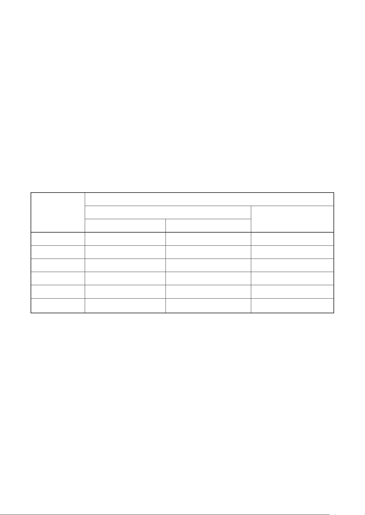
Definition of Protective Gear
When the air conditioner is to be transported, installed, maintained, repaired or removed, wear protective
gloves and ‘safety’ work clothing.
In addition to such normal protective gear, wear the protective gear described below when undertaking the
special work detailed in the table below.
Failure to wear the proper protective gear is dangerous because you will be more susceptible to injury, burns,
electric shocks and other injuries.
Work undertaken
All types of work
Electrical-related work
Work done at heights
(50 cm or more)
Transportation of heavy objects
Repair of outdoor unit
The important contents concerned to the safety are described on the product itself and on this Service Manual.
Please read this Service Manual after understanding the described items thoroughly in the following contents
(Indications/Illustrated marks), and keep them.
Protective gloves
‘Safety’ working clothing
Gloves to provide protection for electricians and from heat
Insulating shoes
Clothing to provide protection from electric shock
Helmets for use in industry
Shoes with additional protective toe cap
Gloves to provide protection for electricians and from heat
Protective gear worn
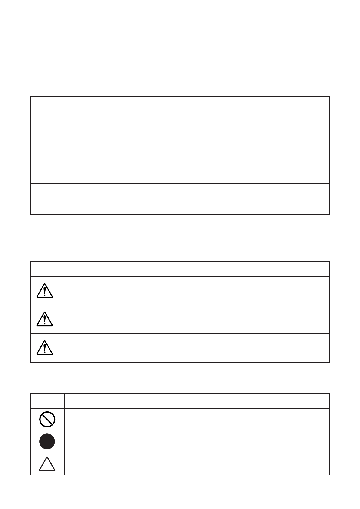
[Explanation of indications]
Indication
Explanation
Indicates contents assumed that an imminent danger causing a death or serious
DANGER
WARNING
CAUTION
∗ Property damage: Enlarged damage concerned to property, furniture, and domestic animal/pet
injury of the repair engineers and the third parties when an incorrect work has
been executed.
Indicates possibilities assumed that a danger causing a death or serious injury of
the repair engineers, the third parties, and the users due to troubles of the
product after work when an incorrect work has been executed.
Indicates contents assumed that an injury or property damage (∗) may be
caused on the repair engineers, the third parties, and the users due to troubles
of the product after work when an incorrect work has been executed.
[Explanation of illustrated marks]
Mark
Indicates prohibited items (Forbidden items to do)
The sentences near an illustrated mark describe the concrete prohibited contents.
Indicates mandatory items (Compulsory items to do)
The sentences near an illustrated mark describe the concrete mandatory contents.
Explanation
Indicates cautions (Including danger/warning)
The sentences or illustration near or in an illustrated mark describe the concrete cautious contents.
4
Page 5
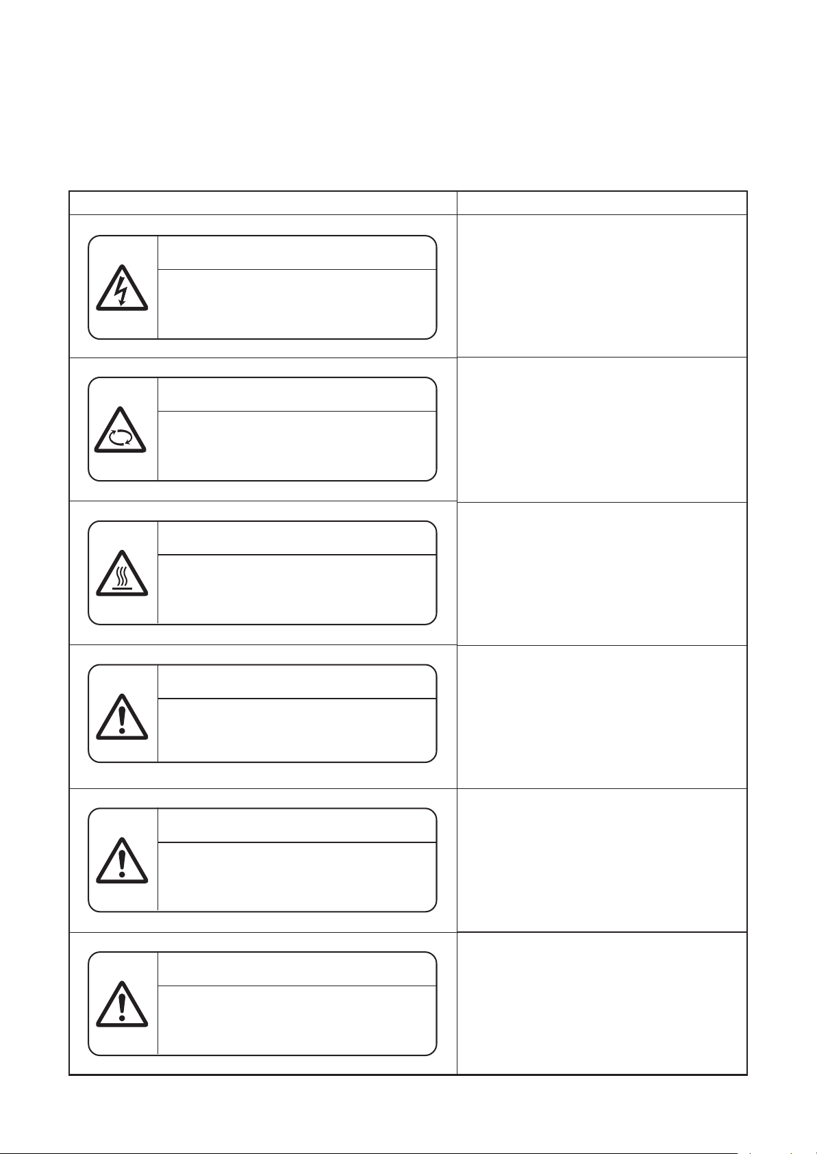
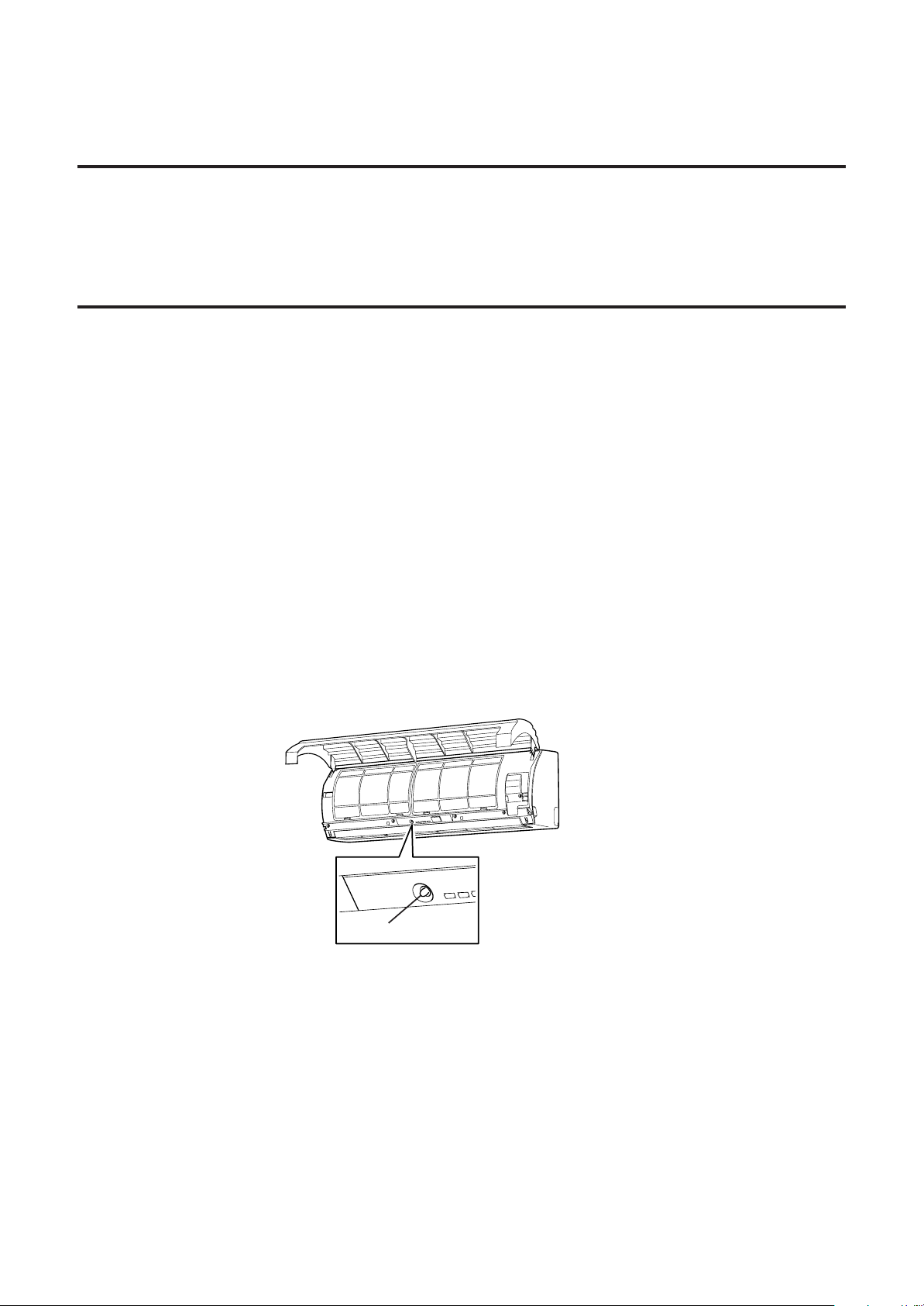
Warning Indications on the Air Conditioner Unit
[Confirmation of warning label on the main unit]
Confirm that labels are indicated on the specified positions
If removing the label during parts replace, stick it as the original.
Warning indication
WARNING
ELECTRICAL SHOCK HAZARD
Disconnect all remote electric
power supplies before servicing.
WARNING
Moving parts.
Do not operate unit with grille removed.
Stop the unit before the servicing.
CAUTION
High temperature parts.
You might get burned when removing this panel.
Description
WARNING
ELECTRICAL SHOCK HAZARD
Disconnect all remote electric power supplies
before servicing.
WARNING
Moving parts.
Do not operate unit with grille removed.
Stop the unit before the servicing.
CAUTION
High temperature parts.
You might get burned when removing this
panel.
CAUTION
Do not touch the aluminum fins of the unit.
Doing so may result in injury.
CAUTION
BURST HAZARD
Open the service valves before the operation,
otherwise there might be the burst.
CAUTION
Do not climb onto the fan guard.
Doing so may result in injury.
CAUTION
Do not touch the aluminum fins of the unit.
Doing so may result in injury.
CAUTION
BURST HAZARD
Open the service valves before the operation,
otherwise there might be the burst.
CAUTION
Do not climb onto the fan guard.
Doing so may result in injury.
5
Page 6
Precautions for Safety
The manufacturer shall not assume any liability for the damage caused by not observing the description of this
manual.
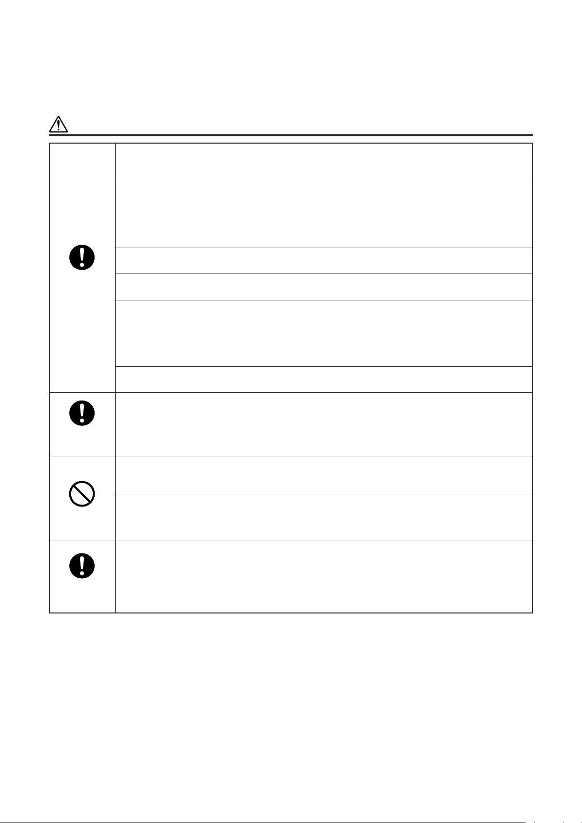
DANGER
Before carrying out the installation, maintenance, repair or removal work, be sure to set the circuit
breaker for both the indoor and outdoor units to the OFF position.
Otherwise, electric shocks may result.
Before opening the intake grille of the indoor unit or service panel of the outdoor unit, set the circuit
breaker to the OFF position.
Failure to set the circuit breaker to the OFF position may result in electric shocks through contact with
the interior parts.
Only a qualified installer (∗1) or qualified service person (∗1) is allowed to remove the intake grille of
the indoor unit or service panel of the outdoor unit and do the work required.
Before starting to repair the outdoor unit fan or fan guard, be absolutely sure to set the circuit breaker
to the OFF position, and place a “Work in progress” sign on the circuit breaker.
Turn off
breaker.
Electric shock
hazard.
When cleaning the filter or other parts of the indoor unit, set the circuit breaker to OFF without fail, and
place a “Work in progress” sign near the circuit breaker before proceeding with the work.
When you have noticed that some kind of trouble (such as when an error display has appeared, there
is a smell of burning, abnormal sounds are heard, the air conditioner fails to cool or heat or water is
leaking) has occurred in the air conditioner, do not touch the air conditioner yourself but set the circuit
breaker to the OFF position, and contact a qualified service person.
Take steps to ensure that the power will not be turned on (by marking “out of service” near the circuit
breaker, for instance) until qualified service person arrives.
Continuing to use the air conditioner in the trouble status may cause mechanical problems to escalate
or result in electric shocks or other failure.
When you access inside of the service panel to repair electric parts, wait for about five minutes after
turning off the breaker. Do not start repairing immediately.
Otherwise you may get electric shock by touching terminals of high-voltage capacitors.
Natural discharge of the capacitor takes about five minutes.
Prohibition
.
Stay on
protection.
Place a “Work in progress” sign near the circuit breaker while the installation, maintenance, repair or
removal work is being carried out.
There is a danger of electric shocks if the circuit breaker is set to ON by mistake.
Before operating the air conditioner after having completed the work, check that the electrical parts box
cover of the indoor unit and service panel of the outdoor unit are closed, and set the circuit breaker to
the ON position.
You may receive an electric shock if the power is turned on without first conducting these checks.
If, in the course of carrying out repairs, it becomes absolutely necessary to check out the electrical
parts with the electrical parts box cover of one or more of the indoor units and the service panel of the
outdoor unit removed in order to find out exactly where the trouble lies, wear insulated heat-resistant
gloves, insulated boots and insulated work overalls, and take care to avoid touching any live parts.
You may receive an electric shock if you fail to heed this warning.
Only qualified service person (*1) is allowed to do this kind of work.
6
Page 7
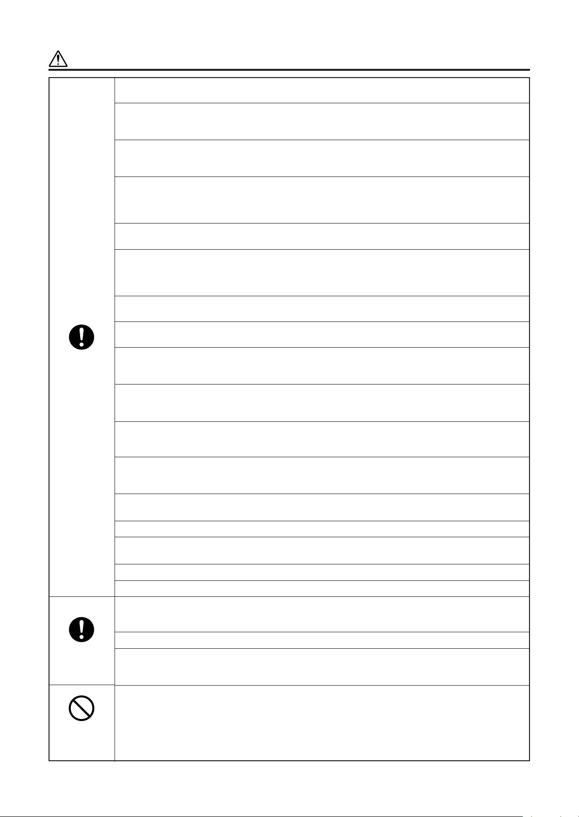
WARNING
General.
Check earth
wires.
Before starting to repair the air conditioner, read carefully through the Service Manual, and repair the
air conditioner by following its instructions.
Only qualified service person (∗1) is allowed to repair the air conditioner.
Repair of the air conditioner by unqualified person may give rise to a fire, electric shocks, injury, water
leaks and/or other problems.
Do not use any refrigerant different from the one specified for complement or replacement.
Other wise, abnormally high pressure may be generated in the refrigeration cycle, which may result in
a failure or explosion of the product or an injury to your body.
Only a qualified installer (∗1) or qualified service person (∗1) is allowed to carry out the electrical work
of the air conditioner.
Under no circumstances must this work be done by an unqualified individual since failure to carry out
the work properly may result in electric shocks and/or electrical leaks.
When transporting the air conditioner, wear shoes with protective toe caps, protective gloves and other
protective clothing.
When connecting the electrical wires, repairing the electrical parts or undertaking other electrical jobs,
wear gloves to provide protection for electricians and from heat, insulating shoes and clothing to
provide protection from electric shocks.
Failure to wear this protective gear may result in electric shocks.
Electrical wiring work shall be conducted according to law and regulation in the community and
installation manual. Failure to do so may result in electrocution or short circuit.
Only a qualified installer (∗1) or qualified service person (∗1) is allowed to undertake work at heights
using a stand of 50 cm or more or to remove the intake grille of the indoor unit to undertake work.
When working at heights, use a ladder which complies with the ISO 14122 standard, and follow the
procedure in the ladder’s instructions.
Also wear a helmet for use in industry as protective gear to undertake the work.
When working at heights, put a sign in place so that no-one will approach the work location, before
proceeding with the work.
Parts and other objects may fall from above, possibly injuring a person below.
When executing address setting, test run, or troubleshooting through the checking window on the
electric parts box, put on insulated gloves to provide protection from electric shock. Otherwise you may
receive an electric shock.
Do not touch the aluminum fin of the outdoor unit.
You may injure yourself if you do so. If the fin must be touched for some reason, first put on protective
gloves and safety work clothing, and then proceed.
Do not climb onto or place objects on top of the outdoor unit.
You may fall or the objects may fall off of the outdoor unit and result in injury.
When transporting the air conditioner, wear shoes with additional protective toe caps.
When transporting the air conditioner, do not take hold of the bands around the packing carton.
You may injure yourself if the bands should break.
Be sure that a heavy unit (10kg or heavier) such as a compressor is carried by two persons.
This air conditioner has passed the pressure test as specified in IEC 60335-2-40 Annex EE.
Before troubleshooting or repair work, check the earth wire is connected to the earth terminals of the
main unit, otherwise an electric shock is caused when a leak occurs.If the earth wire is not correctly
connected, contact an electric engineer for rework.
After completing the repair or relocation work, check that the ground wires are connected properly.
Be sure to connect earth wire. (Grounding work) Incomplete grounding causes an electric shock.
Do not connect ground wires to gas pipes, water pipes, and lightning rods or ground wires for tele-
phone wires.
Prohibition of
modification.
Do not modify the products.
Do not also disassemble or modify the parts.
It may cause a fire, electric shock or injury.
7
Page 8
Use specified
parts.
Do not bring a
child close to
the equipment.
Insulating
measures
No fire
Refrigerant
When any of the electrical parts are to be replaced, ensure that the replacement parts satisfy the
specifications given in the Service Manual (or use the parts contained on the parts list in the Service
Manual).
Use of any parts which do not satisfy the required specifications may give rise to electric shocks,
smoking and/ or a fire.
RefrigerantIf, in the course of carrying out repairs, it becomes absolutely necessary to check out the
electrical parts with the electrical parts box cover of one or more of the indoor units and the service
panel of the outdoor unit removed in order to find out exactly where the trouble lies, put a sign in place
so that no-one will approach the work location before proceeding with the work.
Third-party individuals may enter the work site and receive electric shocks if this warning is not heeded.
Connect the cut-off lead wires with crimp contact, etc., put the closed end side upward and then apply
a watercut method, otherwise a leak or production of fire is caused at the users’ side.
When performing repairs using a gas burner, replace the refrigerant with nitrogen gas because the oil that
coats the pipes may otherwise burn. When repairing the refrigerating cycle, take the following measures.
1) Be attentive to fire around the cycle. When using a gas stove, etc., be sure to put out fire before work;
otherwise the oil mixed with refrigerant gas may catch fire.
2) Do not use a welder in the closed room. When using it without ventilation, carbon monoxide
poisoning may be caused.
3) Do not bring inflammables close to the refrigerant cycle, otherwise fire of the welder may catch the
inflammables.
The refrigerant used by this air conditioner is the R410A.
Check the used refrigerant name and use tools and materials of the parts which match with it.
For the products which use R410A refrigerant, the refrigerant name is indicated at a position on the
outdoor unit where is easy to see. To prevent miss-charging, the route of the service port is changed
from one of the former R22.
For an air conditioner which uses R410A, never use other refrigerant than R410A.
For an air conditioner which uses other refrigerant (R22, etc.), never use R410A.
If different types of refrigerant are mixed, abnormal high pressure generates in the refrigerating cycle
and an injury due to breakage may be caused.
When the air conditioner has been installed or relocated, follow the instructions in the Installation
Manual and purge the air completely so that no gases other than the refrigerant will be mixed in the
refrigerating cycle. Failure to purge the air completely may cause the air conditioner to malfunction.
Do not charge refrigerant additionally.
If charging refrigerant additionally when refrigerant gas leaks, the refrigerant composition in the
refrigerating cycle changes resulted in change of air conditioner characteristics or refrigerant over the
specified standard amount is charged and an abnormal high pressure is applied to the inside of the
refrigerating cycle resulted in cause of breakage or injury. Therefore if the refrigerant gas leaks, recover
the refrigerant in the air conditioner, execute vacuuming, and then newly recharge the specified
amount of liquid refrigerant. In this time, never charge the refrigerant over the specified amount.
When recharging the refrigerant in the refrigerating cycle, do not mix the refrigerant or air other than
R410A into the specified refrigerant. If air or others is mixed with the refrigerant, abnormal high
pressure generates in the refrigerating cycle resulted in cause of injury due to breakage.
After installation work, check the refrigerant gas does not leak.
If the refrigerant gas leaks in the room, poisonous gas generates when gas touches to fire such as fan
heater, stove or cocking stove though the refrigerant gas itself is innocuous.
Never recover the refrigerant into the outdoor unit. When the equipment is moved or repaired, be sure
to recover the refrigerant with recovering device. The refrigerant cannot be recovered in the outdoor
unit; otherwise a serious accident such as breakage or injuryis caused.
Assembly/
Wiring
Insulator
check
After repair work, surely assemble the disassembled parts, and connect and lead the removed wires as before.
Perform the work so that the cabinet or panel does not catch the inner wires. If incorrect assembly or
incorrect wire connection was done, a disaster such as a leak or fire is caused at user’s side.
After the work has finished, be sure to use an insulation tester set (500V Megger) to check the resistance is 1MΩ or more between the charge section and the non-charge metal section (Earth position).
If the resistance value is low, a disaster such as a leak or electric shock is caused at user’s side.
8
Page 9
Ventilation
Compulsion
Check after
repair
When the refrigerant gas leaks during work, execute ventilation.
If the refrigerant gas touches to a fire, poisonous gas generates.
A case of leakage of the refrigerant and the closed room full with gas is dangerous because a shortage
of oxygen occurs. Be sure to execute ventilation.
When the refrigerant gas leaks, find up the leaked position and repair it surely.
If the leaked position cannot be found up and the repair work is interrupted, pump-down and tighten
the service valve, otherwise the refrigerant gas may leak into the room.
The poisonous gas generates when gas touches to fire such as fan heater, stove or cocking stove
though the refrigerant gas itself is innocuous.
When installing equipment which includes a large amount of charged refrigerant such as a multi air
conditioner in a sub-room, it is necessary that the density does not the limit even if the refrigerant leaks.
If the refrigerant leaks and exceeds the limit density, an accident of shortage of oxygen is caused.
Tighten the flare nut with a torque wrench in the specified manner.
Excessive tighten of the flare nut may cause a crack in the flare nut after a long period, which may
result in refrigerant leakage.
Nitrogen gas must be used for the airtight test.
The charge hose must be connected in such a way that it is not slack.
For the installation/moving/reinstallation work, follow to the Installation Manual. If an incorrect
installation is done, a trouble of the refrigerating cycle, water leak, electric shock or fire is caused.
Once the repair work has been completed, check for refrigerant leaks, and check the insulation resistance
and water drainage. Then perform a trial run to check that the air conditioner is running properly.
After repair work has finished, check there is no trouble. If check is not executed, a fire, electric shock
or injury may be caused. For a check, turn off the power breaker.
After repair work (installation of front panel and cabinet) has finished, execute a test run to check there
is no generation of smoke or abnormal sound. If check is not executed, a fire or an electric shock is
caused. Before test run, install the front panel and cabinet.
Be sure to fix the screws back which have been removed for installation or other purposes.
Do not
operate the
unit with the
valve closed.
Check after
reinstallation
Cooling
check
Check the following matters before a test run after repairing piping.
• Connect the pipes surely and there is no leak of refrigerant.
• The valve is opened.
Running the compressor under condition that the valve closes causes an abnormal high pressure resulted
in damage of the parts of the compressor and etc. and moreover if there is leak of refrigerant at connecting
section of pipes, the air is sucked and causes further abnormal high pressure resulted in burst or injury.
Only a qualified installer (*1) or qualified service person (*1) is allowed to relocate the air conditioner. It
is dangerous for the air conditioner to be relocated by an unqualified individual since a fire, electric
shocks, injury, water leakage, noise and/or vibration may result.
Check the following items after reinstallation.
1) The earth wire is correctly connected.
2) The power cord is not caught in the product.
3) There is no inclination or unsteadiness and the installation is stable.
If check is not executed, a fire, an electric shock or an injury is caused.
When carrying out the pump-down work shut down the compressor before disconnecting the refrigerant pipe. Disconnecting the refrigerant pipe with the service valve left open and the compressor still
operating will cause air, etc. to be sucked in, raising the pressure inside the refrigeration cycle to an
abnormally high level, and possibly resulting in reputing, injury, etc.
When the service panel of the outdoor unit is to be opened in order for the compressor or the area
around this part to be repaired immediately after the air conditioner has been shut down, set the circuit
breaker to the OFF position, and then wait at least 10 minutes before opening the service panel.
If you fail to heed this warning, you will run the risk of burning yourself because the compressor pipes
and other parts will be very hot to the touch. In addition, before proceeding with the repair work, wear
the kind of insulated heat-resistant gloves designed to protect electricians.
Take care not to get burned by compressor pipes or other parts when checking the cooling cycle while
running the unit as they get heated while running. Be sure to put on gloves providing protection for
electric shock and heat.
When the service panel of the outdoor unit is to be opened in order for the fan motor, reactor, inverter or the
areas around these parts to be repaired immediately after the air conditioner has been shut down, set the
circuit breaker to the OFF position, and then wait at least 10 minutes before opening the service panel. If
you fail to heed this warning, you will run the risk of burning yourself because the fan motor, reactor, inverter
heat sink and other parts will be very hot to the touch. In addition, before proceeding with the repair work,
wear the kind of insulated heat-resistant gloves designed to protect electricians.
9
Page 10

Installation
Only a qualified installer (∗1) or qualified service person (*1) is allowed to install the air conditioner.
If the air conditioner is installed by an unqualified individual, a fire, electric shocks, injury, water
leakage, noise and/or vibration may result.
Before starting to install the air conditioner, read carefully through the Installation Manual, and follow its
instructions to install the air conditioner.
Be sure to use the company-specified products for the separately purchased parts. Use of nonspecified products may result in fire, electric shock, water leakage or other failure. Have the installation
performed by a qualified installer.
Do not supply power from the power terminal block equipped on the outdoor unit to another outdoor unit.
Capacity overflow may occur on the terminal block and may result in fire.
Do not install the air conditioner in a location that may be subject to a risk of expire to a combustible gas.
If a combustible gas leaks and becomes concentrated around the unit, a fire may occur.
Install the indoor unit at least 2.5 m above the floor level since otherwise the users may injure themselves or receive electric shocks if they poke their fingers or other objects into the indoor unit while the
air conditioner is running.
Install a circuit breaker that meets the specifications in the installation manual and the stipulations in
the local regulations and laws.
Install the circuit breaker where it can be easily accessed by the qualified service person (∗1).
If you install the unit in a small room, take appropriate measures to prevent the refrigerant from
exceeding the limit concentration even if it leaks.
Consult the dealer from whom you purchased the air conditioner when you implement the measures.
Accumulation of highly concentrated refrigerant may cause an oxygen deficiency accident.
Do not place any combustion appliance in a place where it is directly exposed to the wind of air
conditioner, otherwise it may cause imperfect combustion.
Explanations given to user
• If you have discovered that the fan grille is damaged, do not approach the outdoor unit but set the circuit
breaker to the OFF position, and contact a qualified service person to have the repairs done.
Do not set the circuit breaker to the ON position until the repairs are completed.
Relocation
• Only a qualified installer (∗1) or qualified service person (∗1) is allowed to relocate the air conditioner.
It is dangerous for the air conditioner to be relocated by an unqualified individual since a fire, electric shocks,
injury, water leakage, noise and/or vibration may result.
• When carrying out the pump-down work shut down the compressor before disconnecting the refrigerant pipe.
Disconnecting the refrigerant pipe with the service valve left open and the compressor still operating will
cause air, etc. to be sucked in, raising the pressure inside the refrigeration cycle to an abnormally high level,
and possibly resulting in reputing, injury, etc.
(∗1) Refer to the “Definition of Qualified Installer or Qualified Service Person.”
10
Page 11
SPECIFICATIONS
Model
MMK-AP0074MH-E
MMK-AP0094MH-E
MMK-AP0124MH-E
MMK-AP0074MH-TR
MMK-AP0094MH-TR
MMK-AP0124MH-TR
Under 70 dBA
∗
Sound power level (dBA)
Cooling Heating
Main unit (Ceiling panel)
∗∗
∗∗
∗∗
∗∗
∗∗
∗∗
DECLARATION OF CONFORMITY
Weight (kg)
11
11
11
11
11
11
Manufacturer: Toshiba Carrier (Thailand) Co., Ltd.
144/9 Moo5, Bangkadi Industrial Park, Tivanon Road, Tambol Bangkadi,
Amphur Muang, Pathumthani 12000 Thailand
Authorized Representative/ Nick Ball
TCF holder: Toshiba EMEA Engineering Director
Toshiba Carrier UK Ltd.
Porsham Close, Belliver Industrial Estate,
PLYMOUTH, Devon, PL6 7DB.
United Kingdom
Hereby declares that the machinery described below:
Generic Denomination: Air Conditioner
Model/type: Indoor unit
MMK-AP0074MH-E, MMK-AP0094MH-E. MMK-AP0124MH-E
MMK-AP0074MH-TR, MMK-AP0094MH-TR, MMK-AP0124MH-TR
Commercial name: Super Modular Multi System Air Conditioner
Super Heat Recovery Multi System Air Conditioner
MiNi-Super Modular Multi System Air Conditioner (MiNi-SMMS)
Complies with the provisions of the “Machinery” Directive (Directive 2006/42/EC) and the regulations transposing into national law
Complies with the provisions of the following harmonized standard:
EN 378-2: 2008+A1:2009
NOTE
This declaration becomes invalid if technical or operational modifications are introduced without the
manufacturer’s consent.
11
Page 12

• New Refrigerant (R410A)
This air conditioner adopts a new HFC type refrigerant (R410A) which does not deplete the ozone layer.
1. Safety Caution Concerned to New Refrigerant
The pressure of R410A is high 1.6 times of that of the former refrigerant (R22). Accompanied with change
of refrigerant, the refrigerating oil has been also changed. Therefore, be sure that water, dust, the former
refrigerant or the former refrigerating oil is not mixed into the refrigerating cycle of the air conditioner with
new refrigerant during installation work or service work. If an incorrect work or incorrect service is performed, there is a possibility to cause a serious accident. Use the tools and materials exclusive to R410A to
purpose a safe work.
2. Cautions on Installation/Service
(1) Do not mix the other refrigerant or refrigerating oil.
For the tools exclusive to R410A, shapes of all the joints including the service port differ from those of
the former refrigerant in order to prevent mixture of them.
(2) As the use pressure of the new refrigerant is high, use material thickness of the pipe and tools which
are specified for R410A.
(3) In the installation time, use clean pipe materials and work with great attention so that water and others
do not mix in because pipes are affected by impurities such as water, oxide scales, oil, etc. Use the
clean pipes.
Be sure to brazing with flowing nitrogen gas. (Never use gas other than nitrogen gas.)
(4) For the earth protection, use a vacuum pump for air purge.
(5) R410A refrigerant is azeotropic mixture type refrigerant. Therefore use liquid type to charge the refriger-
ant. (If using gas for charging, composition of the refrigerant changes and then characteristics of the air
conditioner change.)
3. Pipe Materials
For the refrigerant pipes, copper pipe and joints are mainly used. It is necessary to select the most appropriate pipes to conform to the standard. Use clean material in which impurities adhere inside of pipe or joint
to a minimum.
(1) Copper pipe
<Piping>
The pipe thickness, flare finishing size, flare nut and others differ according to a refrigerant type.
When using a long copper pipe for R410A, it is recommended to select “Copper or copper-base pipe
without seam” and one with bonded oil amount 40mg/10m or less. Also do not use crushed, deformed,
discolored (especially inside) pipes. (Impurities cause clogging of expansion valves and capillary tubes.)
<Flare nut>
Use the flare nuts which are attached to the air conditioner unit.
(2) Joint
The flare joint and socket joint are used for joints of the copper pipe.
The joints are rarely used for installation of the air conditioner. However clear impurities when using them.
12
Page 13

4. Tools
(1) Required Tools for R410A
Mixing of different types of oil may cause a trouble such as generation of sludge, clogging of capillary, etc.
Accordingly, the tools to be used are classified into the following three types.
1) Tools exclusive for R410A (Those which cannot be used for conventional refrigerant (R22))
2) Tools exclusive for R410A, but can be also used for conventional refrigerant (R22)
3) Tools commonly used for R410A and for conventional refrigerant (R22)
The table below shows the tools exclusive for R410A and their interchangeability.
Tools exclusive for R410A (The following tools for R410A are required.)
Tools whose specifications are changed for R410A and their interchangeability
No.
Used tool
Flare tool
Copper pipe gauge
for adjusting
projection margin
Torque wrench
Gauge manifold
Charge hose
Vacuum pump adapter
Electronic balance for
refrigerant charging
Refrigerant cylinder
Leakage detector
Charging cylinder
Usage
Pipe flaring
Flaring by
conventional flare tool
Connection of flare nut
Evacuating, refrigerant
charge, run check, etc.
Vacuum evacuating
Refrigerant charge
Refrigerant charge
Gas leakage check
Refrigerant charge
air conditioner installation
R410A
Existence of Whether convennew equipment tional equipment
for R410A can be used
Yes *(Note 1)
Yes *(Note 1)
Ye s N o
Yesa No
Ye s N o
Ye s Ye s
Ye s N o
Ye s N o
(Note 2) No
Conventional air
conditioner installation
Whether new equipment
can be used with
conventional refrigerant
Ye s
*(Note 1)
No
No
Ye s
Ye s
No
Ye s
No
(Note 1) When flaring is carried out for R410A using the conventional flare tools, adjustment of
projection margin is necessary. For this adjustment, a copper pipe gauge, etc. are necessary.
(Note 2) Charging cylinder for R410A is being currently developed.
General tools (Conventional tools can be used.)
In addition to the above exclusive tools, the following equipments which serve also for R22 are necessary as the general tools.
(1) Vacuum pump
Use vacuum pump by
attaching vacuum pump adapter. (7) Screwdriver (+, –)
(2) Torque wrench (8) Spanner or Monkey wrench
(3) Pipe cutter (9) Hole core drill
(4) Reamer (10) Hexagon wrench (Opposite side 4mm)
(5) Pipe bender (11) Tape measure
(6) Level vial (12) Metal saw
Also prepare the following equipments for other installation method and run check.
(1) Clamp meter (3) IInsulation resistance tester
(2) Thermometer (4) Electroscope
13
Page 14

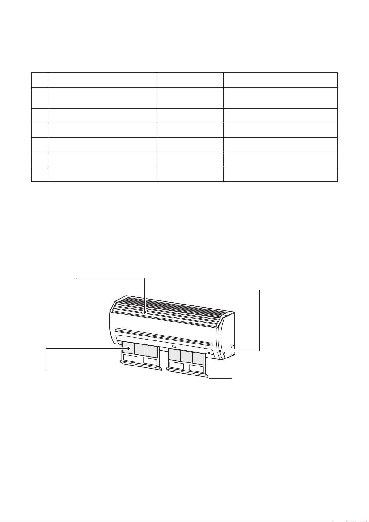
1. CONSTRUCTION VIEWS (EXTERNAL VIEWS)
Model: MMK-AP0074MH∗, AP0094MH∗, AP0124MH
Air inlet part
790
Air outlet gril
790
60
275
60
208
48
6
Knockout
54.5
48
60
∗
275
208
54.5
48
208
48
Knockout
275
6
60
Hock for insulation plate
Refrigerant pipe connecting port
Gas side Ø9.5
(Installation space)
790
790
321
208
275
Drain pipe
Refrigerant pipe connecting port
Liquid side Ø6.4
100mm or more
170mm or more
Note : All dimensions are in mm.
170mm or more
*300mm or more
*(For attached Flow Selector unit of
heat recovery model)
14
Page 15
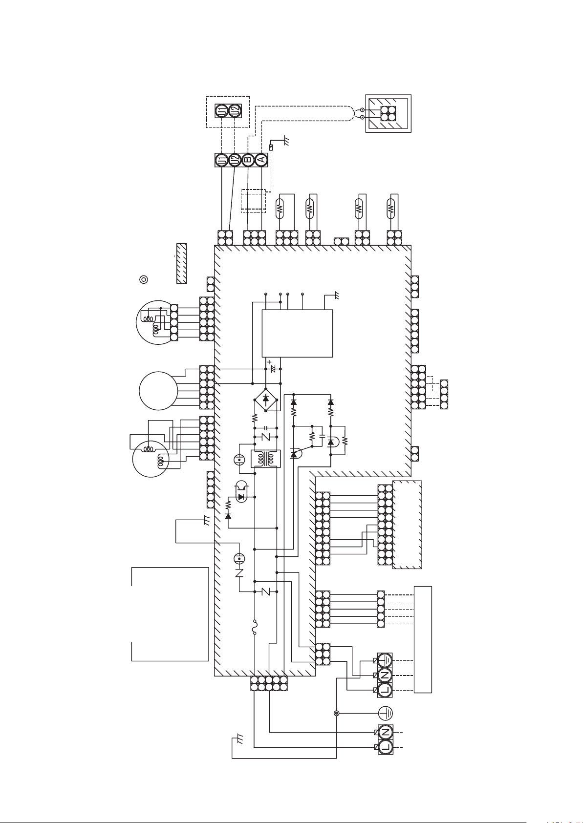
2. WIRING DIAGRAM
Outdoor unit
BLU
BLU
1
2
1
2
CN40
(BLU)
CN44
1. indicates the terminal block.
Letter at inside indicates the terminal number.
2. A dotted line and broken line indicate the
wiring at site.
3. indicates the control P.C.board
12345
WHI
YEL
YEL
YEL
YEL
23456
(BRW)
123456
CN33
(WHI)
BLK
3
321
WHI
1
CN41
(BLU)
Heat
BLK
DC 15V
exchanger
sensor
(TC1)
BLK
1
3
1
2
3
(BRW)
CN100
DC 0V
DC 12V
Powe r
supply
Heat
exchanger
BLK
BLK
1
1
CN101
DC 7V
circuit
sensor
(TC2)
2
2TF1
(BLU)
2
(GRN)
CN103
WHI BLK
Heat
exchanger
sensor
BLK
BLK
1
2
1
2
(YEL)
CN102
2
1
(TCJ)
2
1
Thermo
sensor
BLK
BLK
1
1
CN104
CN80
CN60
CN1(WHI)
Wierd remote
(TA)
2
2
(WHI)
(GRN)
(WHI)
controller
(Sold Separately)
PNL/EMG
Option
Louver
motor
Fan
motor
Pulse motor
valve
F
BLK
BROWN
RED
WHITE
YELLOW
BLUE
BLACK
GRAY
YEL
BLU
BLK
PINK
PNK
GRY
:::::::::::
WHI
RED
BRW
Color identification
RED
BLK
WHI
YEL
BLU
WHI
YEL
ORN
BLU
BRW
RED
HBS
S
ORANGE
GREEN &
YELLOW
ORN
GRN & YEL
13456
13456
12345
123456
6
54321 21
CN22
GREEN
GRN
(WHI)
CN210
CN82
(BLU)
CN50
(WHI)
F301 Fuse
T3. 15A 250V~
1
1
WHI
RED
65432121 654321 321
654321
HA
4321
CN61
(MCC-1510)
BLU
10
RED
987654321109874321
ORN
GRY
54321
54321
1 3
1 3
CN309
(YEL)
GRN & YEL
YEL
BRW
WHI
PNK
GRY
YEL
BRW
WHI
WHI
RED
GRN & YEL
CN213 (WHI)
CN81 (BLK)
3
5
3
CN67
(BLK)
(YEL)
Control P.C.board for indoor unit
CN32
(WHI)
Fan Drive
123456
234567
78
9
1011
(MCC-861)
and indication parts
Infrared rays receive
Flow selector Unit
(Sold sepalately)
9
54321
Heat exchanger
15
220V 60Hz
GRN & YEL
Single phase
Power Supply
220-240V 50Hz
Page 16
3. PARTS RATING
3-1. Parts Rating
No.
1
Fan motor (for indoor)
2
Grille motor
3
Thermo. Sensor (TA sensor)
4
Heat exchanger sensor (TC1 sensor)
5
Heat exchanger sensor (TC2 sensor)
6
Heat exchanger sensor (TCJ sensor)
Parts Name
3-2. Name of Each Part
Type
ICF-340-30
MF-340-30
MP24Z
318mm
Ø4, 600mm
Ø6, 800mm
Ø6, 800mm
Specications
Output (Rated) 30W, 280-340V DC
10kΩ at 25°C
10kΩ at 25°C
10kΩ at 25°C
10kΩ at 25°C
Air inlet grille
Air in the room is sucked from here.
Air filter
Removes dust and trash.
(Air filter is provided in the air inlet grille.)
Earth screw
Earth screws are provided in the electric parts box.
Air outlet/Air outlet flap
Change the direction of the air to be
discharged according to cool/heat mode.
16
Page 17
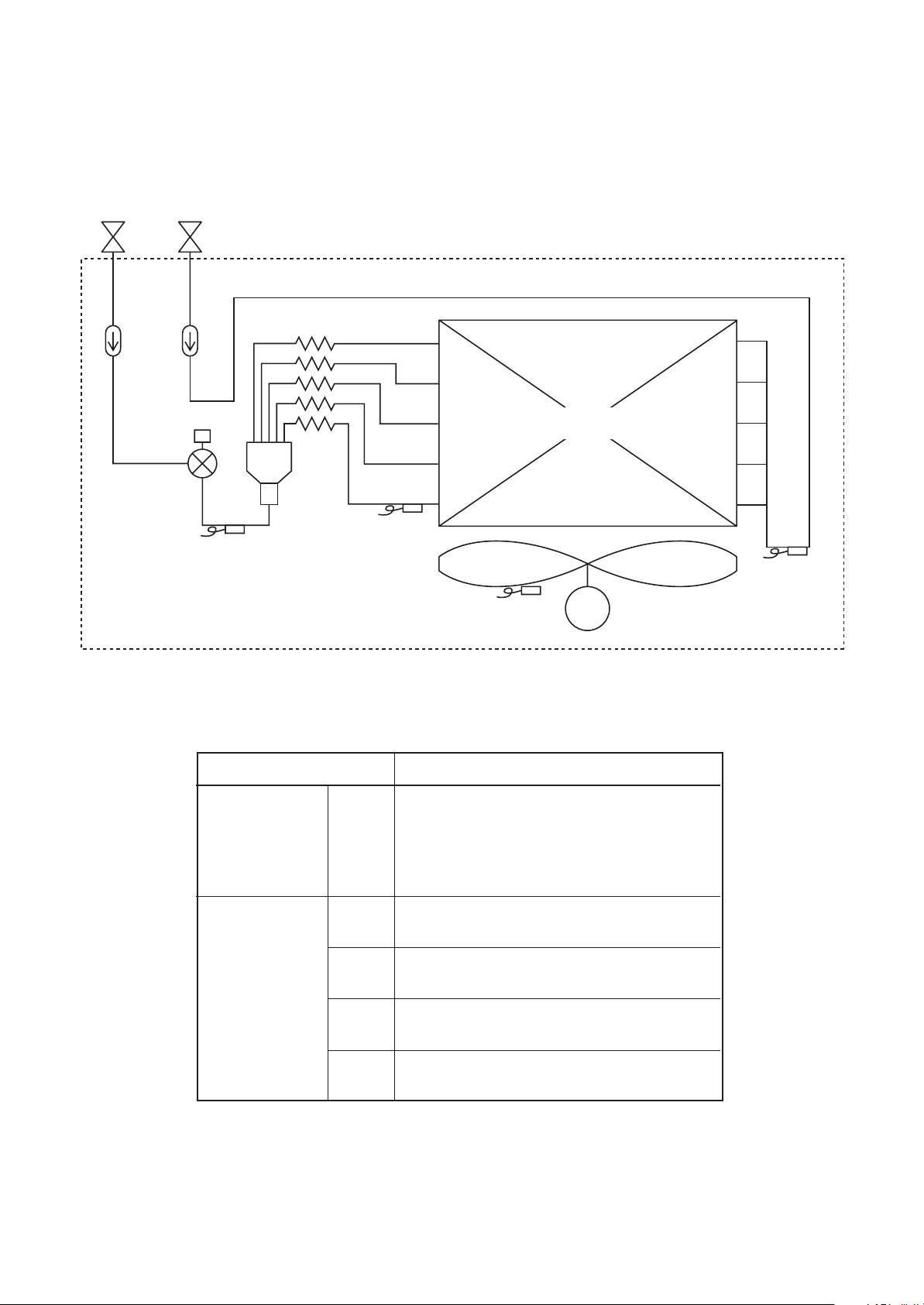
4. REFRIGERANTING CYCLE DIAGRAM
Gas sideLiquid side
Strainer
Pulse Motor
Valve (PMV)
Sensor
(TC2)
Capillary tube
Strainer
Sensor
(TCJ)
Air heat exchanger
at indoor side
Fan
Sensor
(TA)
M
Sensor
(TC1)
Fan motor
Functional part name
Pulse Motor Valve PMV
Temp. sensor 1. TA
2. TC1
3. TC2
4. TCJ
Functional outline
(Connector CN082 (6P): Blue)
1) Controls super heat in cooling operation
2) Controls under cool in heating operation
3) Recovers refrigerant oil in cooling operation
4) Recovers refrigerant oil in heating operation
(Connector CN104 (2P): White)
1) Detects indoor suction temperature
(Connector CN100 (3P): Brown)
1) Controls PMV super heat in cooling operation
(Connector CN101 (2P): Blue)
1) Controls PMV under cool in heating operation
(Connector CN102 (2P): Yellow)
1) Controls PMV super heat in cooling operation
17
Page 18
5. CONTROL OUTLINE
5-1. Indoor Unit Control Specifications
No.
1
2
Item
Power supply
is reset.
Operation
select
Outline of specifications
(1) Distinction of outdoor unit
When the power supply is reset, the outdoor units are
distinguished, and control is exchanged according to the
distinctive results.
(2) Check code clear
When the power supply is reset, the check code is also reset
once. If an abnormal status which the check code appears
after Start/Stop button of the remote controller has been
pushed continues, the check code is displayed again on the
remote controller.
(1) Based upon the operation select command from the remote controller or central controller, the
operation mode is se-lected.
Remote controller command
STOP
FAN
COOL
DRY
HEAT
AUTO
(2) Operation commend permission mode
Neither AUTO mode of the standard model nor HEAT mode of Cooling-only model can be
selected. When a wireless remote control is used, the mode is notified by the receiving sound
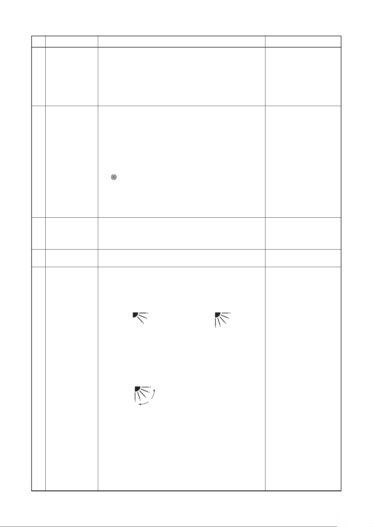
Pi, Pi (Twice) and alternative flashing of “
To release the alternative flashing, change the mode on the wireless remote controller.
Cooling or HEAT operation mode is automatically selected
by Ta and Ts and the unit starts operation.
” and “ ”.
Control outline
Stops air conditioner.
Fan operation
Cooling operation
Dry operation
Heating operation
• Judgment of outdoor unit
• Exchange of cooling-only
unit
• Exchange of standard
model with the flex model
Remarks
3
Room temp.
control
4
Automatic
capacity
control
5
Air volume
control
(1) Adjustment range Set temperature on remote controller (°C)
In cooling/drying
Wired type
Wireless type
(2) From the item code 06, the setup temperature in heating
operation can be corrected.
Setup data
Setup temp. correction
Setup at shipment
Setup data
(1) Based upon difference between Ta and Ts, the operation
frequency of the outdoor unit varies.
(1) By the command from the remote controller, “HIGH (HH)”,
“MED (H)”, or “LOW (L)” “AUTO” operation is executed.
For the wireless remote controller type, “HH”, “H+”, “H”, “L+”,
“L”, or “AUTO” operation is executed.
(2) While air speed is in AUTO mode, the air speed is changed
according to the difference between Ta and Ts.
18 to 29°C
17 to 30°C
0246
+0°C +2°C +4°C +6°C
2
In heating
18 to 29°C
17 to 30°C
Heating suction temperature
shift
Ta: Room temperature
Ts: Setup temperature
HH > H+ > H >
L+ > L > LL
18
Page 19
No.
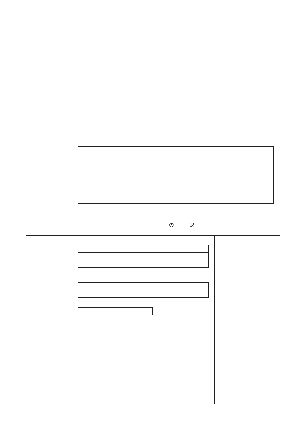
6
Prevention of
cold air
discharge
7
Freeze prevention control
(Low temp.
release)
Item
Outline of specifications
(1) In heating operation, the upper limit of the fan tap is set by
one with higher temperature of TC2 sensor and TCJ sensor.
• When B zone has continued for 6 minutes, the operation
shifts to C zone.
• In defrost time, the control point is set to +6°C.
(˚C)
36
34
32
30
D
C
A zone: OFF
B zone:
Over 30˚C, below 32˚C, UL
C zone:
E
Over 32˚C, below 24˚C, L
D zone:
Over 24˚C, below 36˚C, H
E zone: HH
24
20
B
A
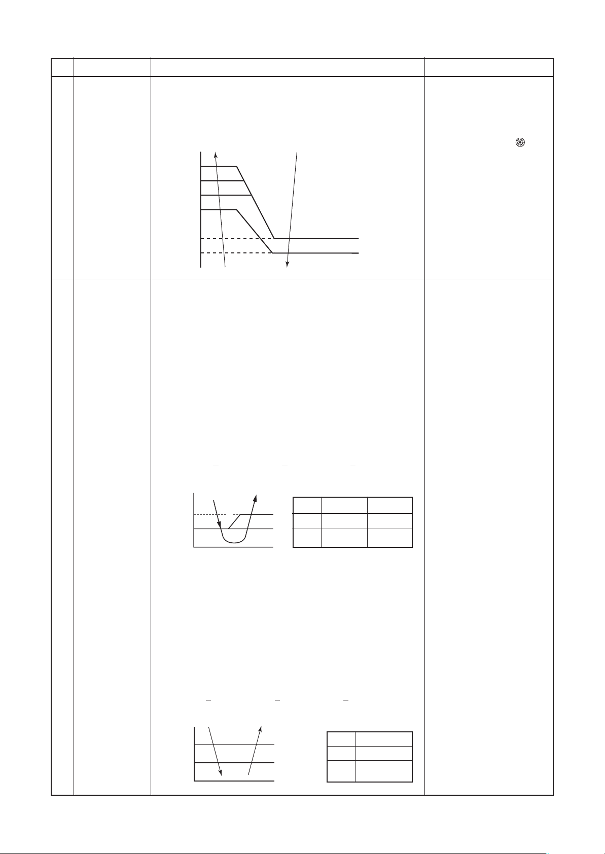
(1) In cooling operation, the air conditioner operates as de-
scribed below based upon temp. detected by TC1, TC2 and
TCJ sensors.
To prevent the heat exchanger from freezing, the operation
stops.
• When “J” zone is detected for 5 minutes, the forced
thermo is OFF.
• In “K” zone, the timer count is interrupted, and held.
• When “1 ” zone is detected, the timer is cleared and the
operation returns to the normal operation.
• When the forced thermo-OFF became S0 with continuation of “J” zone, operation of the the indoor fan in LOW (L)
mode until it reaches the “1 ” zone.
It is reset when the following conditions are satisfied.
Reset conditions
1) TC1
> 12°C and TC2 > 12°C and TCJ > 12°C
2) 20 minutes passed after stop.
Remarks
• In D and E zones, priority
is given to remote controller air speed setup.
• In A and B zones, “
” is
displayed.
(˚C)
P1
Q1
I
K
J
a
P1
10°C (5°C) 10°C
Q1
0°C –14°C
(2) In cooling operation, the air conditioner operates as
described below based upon temp. detected by TC2 and
TCJ sensors.
• When “M” zone is detected for 45 minutes, the forced
thermo is OFF.
• In “N” zone, the timer count is interrupted and held.
• When shifting to “M” zone again, the timer count restarts
and continues.
• If “L” zone is detected, the timer is cleared and the
operation returns to normal operation.
Reset conditions
TC1 TC2, TCJ
>
1) TC1
12°C and TC2 > 12°C and TCJ > 12°C
2) 20 minutes passed after stop.
(˚C)
P2
Q2
L
N
M
P2
Q2
TC2, TCJ
–2.0°C
5°C
19
Page 20
No.
8
Cooling oil
(refrigerant)
recovery control
9
Heating refrigerant (oil) recovery
control
Item
Outline of specifications
While the outdoor unit is recovering cooling oil (refrigerant), the
indoor units perform the following control tasks:
[common for operational (cooling thermo ON/thermo OFF/FAN),
as well as nonoperational indoor units]
(1) Open the indoor PMV to a certain degree.
(2) Engage in recovery control for a specified period of time
and return to normal cooling operation at the end of this
period upon terminating the control.
While the outdoor unit is recovering heating refrigerant (oil), the
indoor units perform the following control tasks:
(1) Open the indoor PMV to a certain degree.
(2) Control the indoor fan according to the operation mode.
[Indoor units operating in heating thermo ON/OFF state]
Let the indoor fan continue operating, but turn it off if the
temperature of the indoor heat exchanger drops.
[Indoor units operating in FAN mode]
Turn off the indoor fan and display “HEATING STANDBY
” on the remote controller.
[Non-operational indoor units]
Keep the indoor fan turned off.
(3) Terminate the recovery operation depending on the TC2
temperature reading. The timing of termination is determined by each indoor unit.
Remarks
• Recovery operation
normally takes place
roughly every 2 hours.
• The opening position of
the indoor PMV
depending on the type
and capacity of the
indoor unit.
• Recovery operation
normally takes place
roughly every hour.
• The opening position of
the indoor PMV
depending on the type
and capacity of the
indoor unit.
10
Short intermittent
operation
compensation
control
11
Elimination of
remaining heat
12
Flap control
(1) For 5 minutes after the operation has started, the operation
is continued even if entering thermostat-OFF condition.
(2) However, Cooling/Heating exchange and the system
protective control precede and thermostat is OFF.
(1) When the air conditioner stops in the “HEAT” mode, drive
the indoor fan with “LOW” mode for approx. 30 seconds.
(1) Flap position setup (Wired type)
• The flap position can be set up in the following operation
range.
In cooling/dry operation In heating/fan operation
• In group operation, the flap positions can be set up
collectively or individually.
(2) Swing setup
• The swinging position can be moved in the following
operation range.
All modes
• In group operation, the swinging positions can be set up
collectively or individually.
(3) Fix set up (Wireless type)
Keep pressing or pressing briefly the FIX button to move
the flap in the desired direction.
Operating angle of flap will be different during cooling, dry
and heating operation.
(4) When the unit stops, the flap automatically closes.
(5) While the heating operation is ready, the flap automatically
moves upward.
20
Page 21
No.
Item
Outline of specifications
Remarks
13
Filter sign display
(None in wireless type)
∗ Provided in the
separately laid type
TCB-AX21E2.
14 Operation standby
Heating standby
(1) The operation time of the indoor fan is integrated and
stored in memory, and the filter exchange signal is
sent to the remote controller to display on the remote
controller LCD after the specified time. (150H)
(2) When the filter reset signal is received form the remote
controller, time of the integrated timer is cleared. In this
time, if the specified time has passed, the measured
time is reset and LCD display disappears.
<Operation standby> .. Displayed on wired remote controller
(1) When any of the DN codes listed below is displayed
• “P05” - Detection of an open phase in the power
supply wiring
• “P10” - Detection of indoor flooding in at least one
indoor unit
• “L30” - Detection of an interlock alarm in at least one
indoor unit
(2) Forced thermo OFF
• “COOL/DRY” operation is unavailable because at
least one indoor unit is operating in “HEAT” mode.
• “HEAT” operation is unavailable because at least one
indoor unit is operating in “COOL/DRY” mode under
priority cooling setting (bit 1 of SW11 on outdoor I/F
P.C. board ON).
(3) All indoor units not able to engage in any of the above
operations stand by in thermo OFF state.
(4) The indoor fan has been turned off because the
system is engaged in a heat refrigerant (oil) recovery
operation.
• “OPERATION STANDBY
” displayed
No display provided on
wireless remote controller
15 Selection of central
control mode
Operation via
TCC-Link
central
control
Individual
Central 1
Central 2
Central 3
Central 4
Start/stop
selection
¡
×
×
¡
¡
<Heating standby> ...... Displayed on wired remote controller
(1) Normal thermo OFF
• During heating, the indoor unit goes thermo OFF as
the heating temperature setting is reached.
(2) During heating, the fan rotates at a breeze speed
(UL or lower) or remains stationary to prevent cold air
from being discharged (including defrosting operation).
(3) Forced thermo OFF
• “HEAT” operation is unavailable because at least one
indoor unit is operating in “COOL/DRY” mode under
priority cooling setting (bit 1 of SW11 on outdoor I/F
P.C. board ON).
(1) The range of operations that can be performed via an
indoor unit remote controller can be determined
through the setting of the central controller.
(2) Setting details
TCC-Link central control
Operation via RBC-AMT32E
Operation
mode
selection
¡
¡
×
×
×
Timer
setting
¡
×
×
¡
¡
Temperature
setting
¡
¡
×
×
¡
Fan
speed
setting
¡
¡
¡
¡
¡
Air flow
direction
setting
¡
¡
¡
¡
¡
RBC-
AMT32E
display
“CENTRAL
CONTROL IN
PROGRESS”
• “HEATING STANDBY
displayed
• In the case of a wired
remote controller, “CENTRAL CONTROL IN
PROGRESS
displayed (lit up) while in
central control mode.
• The display blinks when a
control function
inaccessible to a remote
controller is chosen.
• A wireless remote
controller has the same
set of control functions,
although there is no
display.
When a control operation
is performed via a wireless
remote controller while in
central control mode, a
peep sound alert (5 times)
is provided.
” is
”
21
Page 22
No.
16
Hi POWER
operation
(Wireless remote
control specific
operations)
17
ECO timer
operation
(Wireless remote
control specific
operations)
Item
Outline of specifications
When you press the Hi POWER button during cooling,
heating or A operation, the air conditioner will start the
following operation.
• Cooling operation
Performs the cooling operation at 1°C lower than the setting
temperature.
Only when the fan speed before the Hi POWER operation is
not high, the fan speed will be increased.
• Heating operation
Performs the heating operation at 2°C higher than the
setting temperature.
Only when the fan speed before the Hi POWER operation is
not high, the fan speed will be increased.
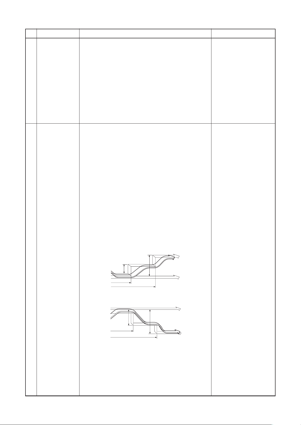
When you press the ECO button during cooling, heating or A
operation, the air conditioner will start the following operation.
The fan speed display will indicate AUTO and low speed will
be used.
• Cooling operation
In the operation suppression zone, where capacity is kept to
the minimum, overcooling is prevented by raising the
temperature setting by 1°C after 1 hour and by 2°C after 2
hours of operation.
The room temperature is thus regulated between the
operation suppression zone and the set temperature.
Remarks
• Heating operation
In the operation suppression zone, where capacity is kept to
the minimum, overheating is prevented by lowering the
temperature setting by 1°C after 1 hour and by 2°C after 2
hours of operation.
The room temperature is thus regulated between the set
temperature and the operation suppression zone.
Operation suppression zone
1˚C
1 hour
2 hours
Operation starts
Set temperature
1˚C
1 hour
Operation starts
2 hours
2˚C
Set temperature
2˚C
Operation
suppression zone
22
Page 23
No.
SAVE
18
MEMORY operation
Item
Outline of specifications
Start the air conditioner in the operation mode which
you want the remote control to memorize.
(1) Press this button briefly to standby memorizing the
setting.
All the icons currently displayed except for the clock
display and mark flashes.
Remarks
19
PRESET operation
(2) Press and hold the MEMO button for more than 3
seconds while the display flashes.
The mark is indicated and the setting is memorized.
• If you do not press the MEMO button within 3
seconds or if you press another button, the
MEMORY setting is cancelled.
• Operation modes which can be memorized with
the MEMO button are MODE, Temperature, FAN,
TIMER and Hi POWER.
To operate the air conditioner with the setting memorized by the MEMO button.
(1) Press the PRESET button. The setting memorized
with the MEMO button will be indicated and the air
conditioner operates with regards to the setting.
• The lamp (green) on the display panel of the
indoor unit goes on, and operation starts after
approximately 3 minutes.
• Initial setting:
MODE : AUTO
Temperature : 22
(1)
(2)
(1)
START/STOP
FAN MODE
SWING
TIMER
FIX
ON
OFF SET CLR
FILTER
START/STOP
FAN MODE
G
SWIN
TIMER
FIX
ON
OFF SET CLR
FILTER
ECO
ECO
PRESET
AUTO
Hi-POWER
MEMO
CLOCK CHECKRESET
PRESET
AUTO
Hi-POWER
MEMO
CLOCK CHECKRESET
20 DC motor 1) When the fan stator, positioning is performed for the
starter and the rotor. (Vibrate slightly)
2) DC motor operates according to the command from
the indoor controller.
(Note)
If the fan lock was detected, the operation of the indoor
unit stops and the error is displayed.
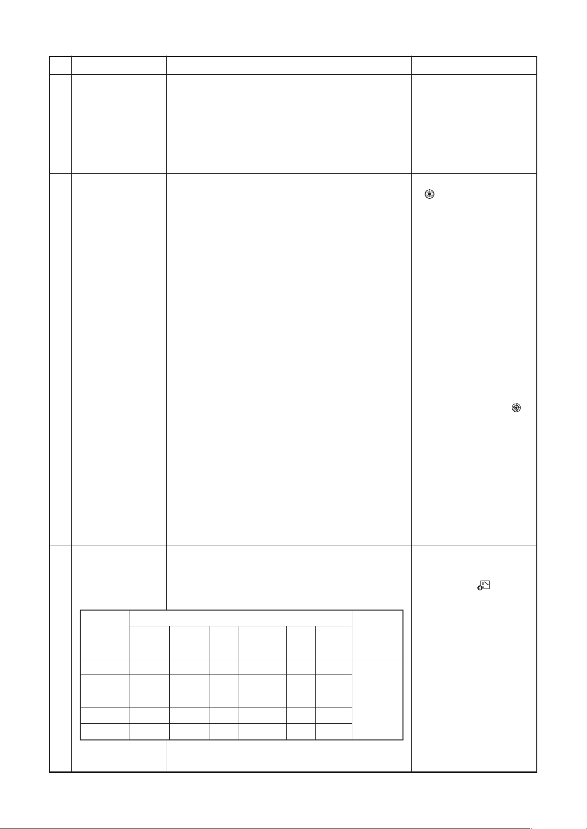
21 Save operation 1) The save operation starts when
button on the
remotecontroller is turned on.
2) While the save operation is performed,
segment
goes on the screen of the wired remote controller.
3) The request capacity ratio is restricted to approx.
75% during save operation.
4) If the save operation was validated, the contents are
held during the operation stop, the operation mode
change and the resetting of power supply. Therefore
the operation at the next time also will be activated
with “Save operation is valid”
23
Check code [P12]
Page 24
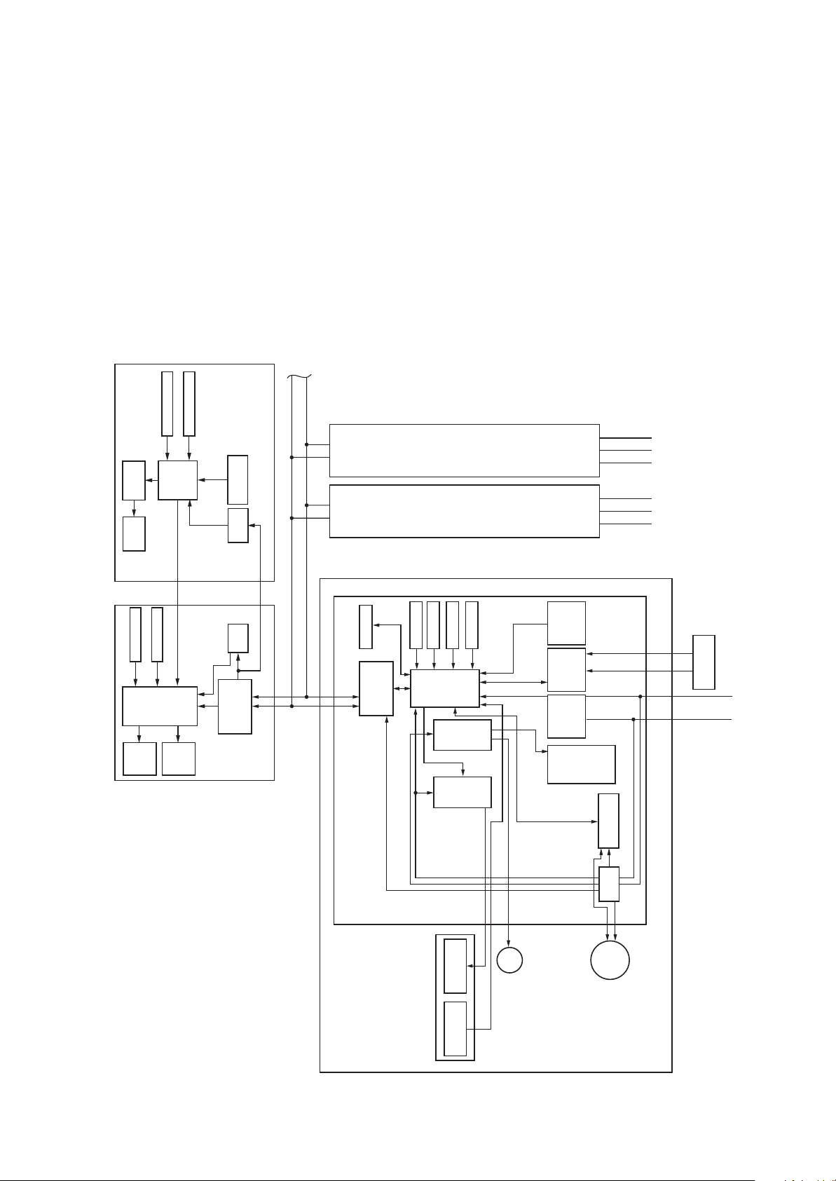
6. CONFIGURATION OF CONTROL CIRCUIT
6-1. Indoor Controller Block Diagram
6-1-1. Case of Main (Sub) Remote Controller Connected
Max. 8 units are connectable.
*1 In group connection, mount the
central control remote controller to
group header unit.
*2 Connection of weekly timer to sub
remote controller is unavailable.
Function setup
Key switch
LCD
driver
LCD
Display
Central remote controller
Function setup
Key switch
part
LCD
Wired (Simple)
Display
master remote controller
(Up to 2 sets)
CPU
CN2
Display
CPU
CN1
part
LED
Secondary
DC5V
Powe r
Powe r
DC5V
Remote
controller
battery
circuit
circuit
circuit
communication
A B
A B
2
*
EEPROM
B
A
Remote
controller
communication
DC20V
circuit
DC12V
TC sensor
TA sensor
DC5V
Same
as left
Same
as left
TCJ sensor
CPU
H8/3039
DriverDriver
HA
Outside
output
Remote
A/B setup
controller
BUS
circuit
communication
AC
circuit
signal input
synchronous
Start
Alarm
Ready
Thermostat ON
1 23
1 23
FAN
HEAT
COOL
Fan motor
control circuit
unit
Outdoor
unit
Outdoor
L N U1 U2
U1 U2
Outdoor unit
Power supply
1Ø, 220V, 60Hz
1Ø, 220 - 240V, 50Hz
Main P.C. board (MCC-1510)
Indoor unit
#1
24
(MCC-819)
Sensor display P.C. board
LED
Sensor part
Louver
motor
circuit
Powe r
Indoor
fan motor
DC280V
Page 25
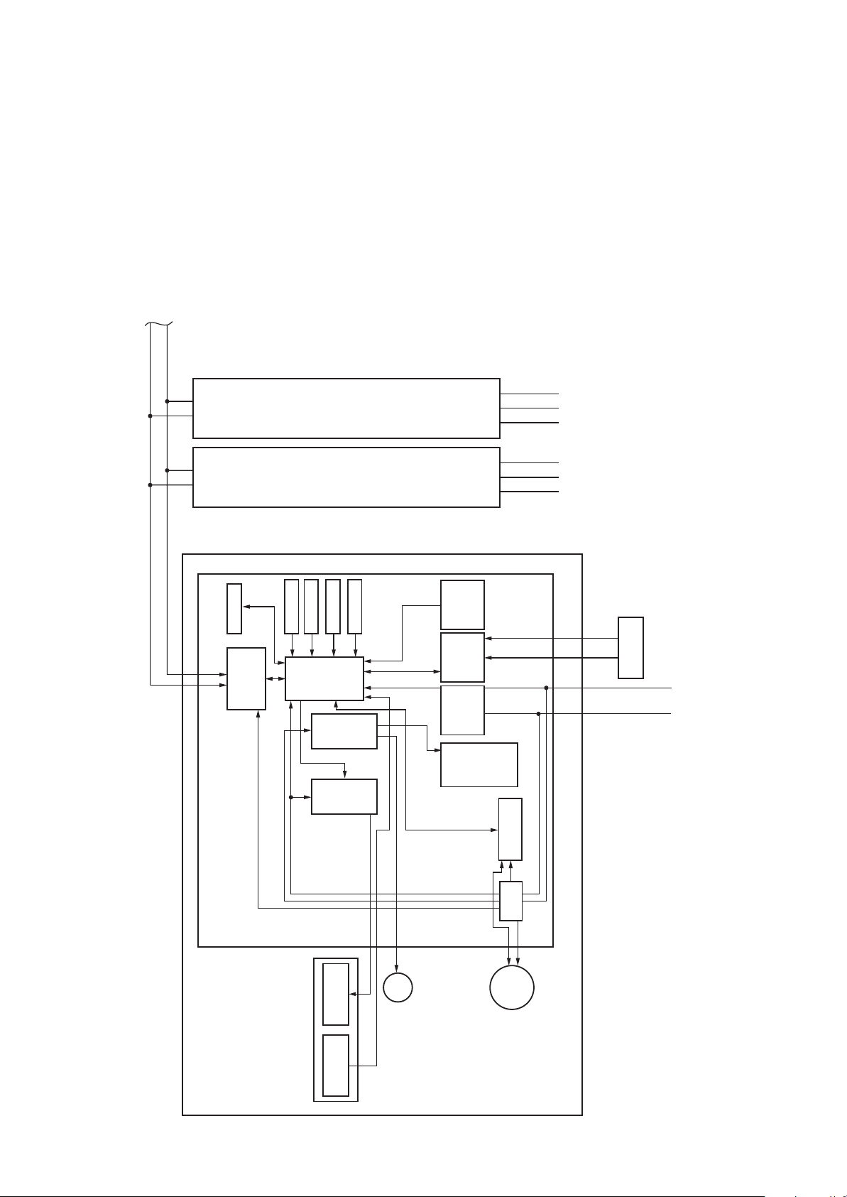
6-1-2. Case of Wireless Remote Controller Kit Connected
Max. 8 units are connectable.
*1 In group connection, mount the
central control remote controller to
group header unit.
A B
A B
EEPROM
B
circuit
A
Remote
controller
communication
TC sensor
TA sensor
Same
as left
Same
as left
TCJ sensor
CPU
H8/3039
DriverDriver
HA
Outside
output
Remote
A/B setup
controller
circuit
receive
Serial send/
AC
circuit
signal input
synchronous
Start
Alarm
Ready
Thermostat ON
1 23
1 23
FAN
HEAT
COOL
unit
Outdoor
unit
Outdoor
LN U2U1
U1 U2
Outdoor unit
Power supply
1Ø, 220V, 60Hz
1Ø, 220 - 240V, 50Hz
Main P.C. board (MCC-1510)
Indoor unit
#1
DC20V
DC12V
DC5V
(MCC-819)
Sensor display P.C. board
LED
Sensor part
Louver
motor
25
Fan motor
control circuit
circuit
Powe r
DC280V
Indoor
fan motor
Page 26
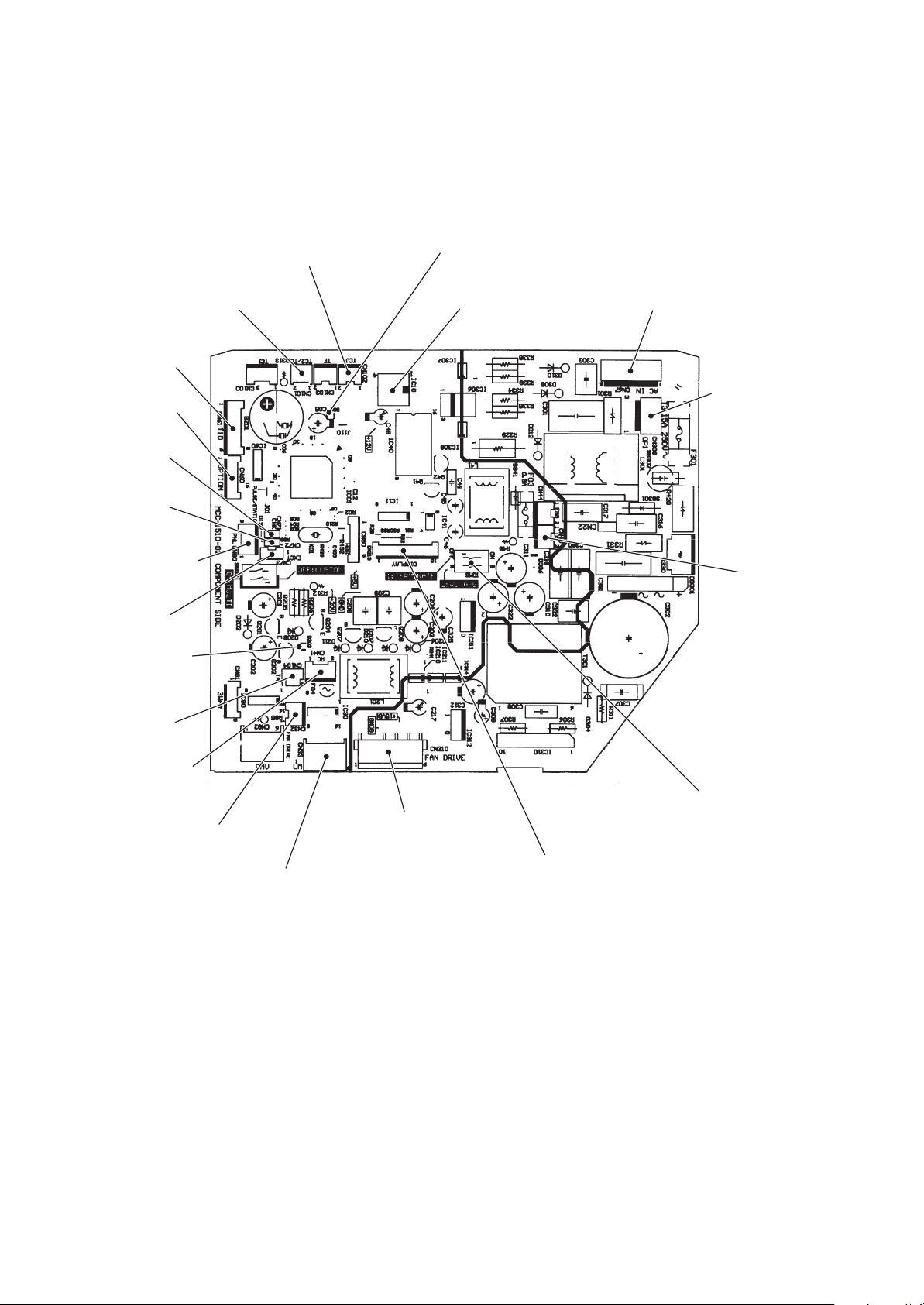
6-2. Indoor P.C. Board
MCC-1510
HA (T10)
CN61, DC 12V
Option output
CN60, DC 12V
CHK
CN71, DC 5V
DISP
CN72, DC 5V
Outside error input
CN80, DC 12V
EXCT
CN73, DC 5V
Remote controller
power LED
D203
TCJ sensor
CN102, DC 5V
TC sensor
CN101, DC 5V
Microcomputer operation LED
D02
EEPROM
IC10
Inter-unit wire
CN67, AC 200V
Option power supply
CN309, AC 200V
Central control
CN40, DC ± 5V
TA sensor
CN104, DC 5V
Remote controller
CN41, DC 20V
Fan drive
CN32, DC 12V
Louver
CN33, DC 20V
DC fan input/output
CN210
Terminator resistor provided/not provided
Remote controller A/B switch
SW01
Display output/Wireless sensor
CN213, DC 5V
26
Page 27
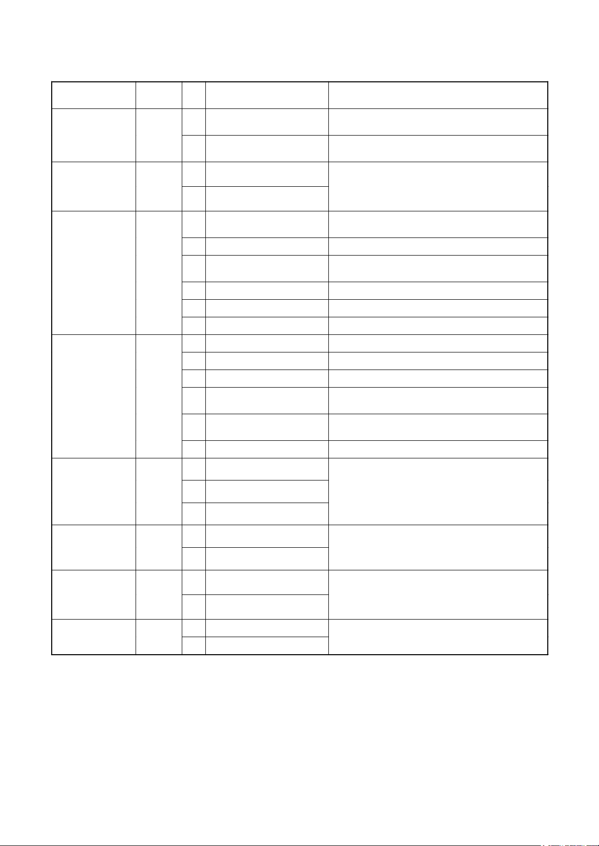
Wall-Type P.C. Board Optional Switch/Connector Specifications
Function
Terminator resistor
provided/Not provided
Remote controller A/B
Fan output CN32
HA CN61
Connector
No.
SW01
Pin
No.
OFF: No terminator resistor,
Bit 1
ON: Terminator resistor provided
OFF: Remote controller A
Bit 2
ON: Remote controller B
1 DC12V
2 Output
1 Start/Stop input
2 0V (COM)
3 Handy prohibition input
4 Operation output ON during operation (Answer back of HA)
5 DC12V (COM)
6 Alarm output ON during output of alarm
1 DC12V (COM)
2 Defrost output ON during defrosting of outdoor unit
3 Thermo-ON output ON when Real thermo. ON (Comp. ON)
Specifications Remarks
Setup at shipment OFF: No terminator resistor.
Only 1 unit is ON during central control by custom only.
Setup at shipment OFF: Remote controller A
Setup at shipment: Linked operation of ON with operation of
indoor unit and OFF with stop
* The setup of single operation by FAN button on remote
controller is executed from remote controller. (DN = 31)
HA Start/Stop input (J01: Provided/Not provided =
Pulse (At shipment from factory)/Static input switch)
Operation stop of handy remote controller is permitted /
prohibited by input.
Optional output CN60
Outside error input CN80
CHK
CN71
Operation check
DISP
CN72
Display mode
CN73
Demand
4 Cooling output
5 Heating output
6 Fan output ON when indoor fan is ON
1 DC12V (COM)
2 DC12V (COM)
3 Filter/Option/Outside error input
1 Check mode input
2 0V
1 Display mode input
2 0V
1 Demand input EXCT
2 0V
ON when operation mode is cooling line
(Cool, Dry, Cooing/Heating AUTO cooling)
ON when operation mode is heating line
(Heat, Cooling/Heating AUTO heating)
At shipment from factory, the error code “L30” generates and
optional error input to stop operation forcedly (DN:2A = 1) is
controlled (Display of protection for devices attached to outside)
by setup of outside error input (DN:2A = 2) for 1 minute.
* Optional error input control is set up on the remote
controller.
This check is used for operation check of indoor unit.
(The specified operation such as indoor fan “H”, drain pump
ON, etc. is executed without communication with outdoor
unit or remote controller.)
Display mode, communication is enabled by indoor unit and
remote controller only.
(When power supply is turned on.)
Timer short (Usual)
Indoor unit forced thermo-OFF operation
27
Page 28

ON / OFF
SET
T
ST
T
CL
SAVE
S
X
E
U
R
6-3. Functions at test run
n Cooling/Heating test run check
The test run for cooling/heating can be performed from either indoor remote controller or outdoor interface P.C.
board.
1. Start/Finish operation of test run
¤ Test run from indoor remote controller
Wired remote controller: Refer to the below item of “Test run” of the wired remote controller.
Wireless remote controller: Refer to the next page item of “Test run” of the wireless remote controller.
u In case of wired remote controller
<RBC-AMT32E> <RBC-AMS41E>
1,
5
Procedure
1
2
3
2,
4
TIMER SE
MOD
3
RESE
TE
WING/FI
NIT LOUVE
1,
5
Operation contents
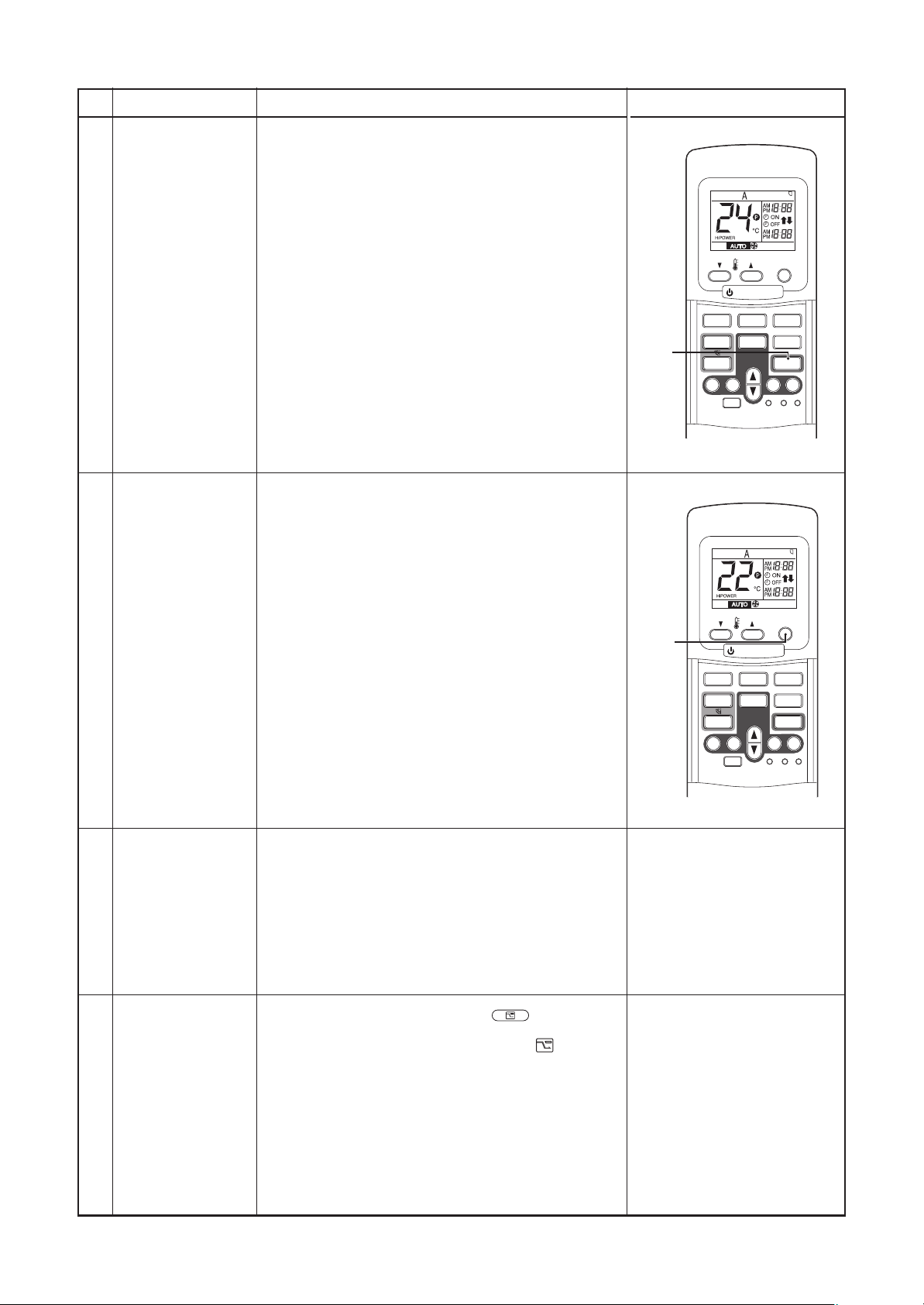
Push [TEST] button for 4 seconds or more.
[TEST] is displayed at the display part and
the mode enters in TEST mode.
Push [ON/OFF] button.
Change the mode from [COOL] to [HEAT] using [MODE] button.
• Do not use [MODE] button for other mode except
[COOL]/[HEAT] modes.
• The temperature cannot be adjusted during test run.
• The error detection is performed as usual.
TEMP.
FILTER UP/DN
DAY
PROGRAM
TEST
FLT.RESET
SCHEDULE
TIME SAVE
SET CL
FAN
SWING/FIX
TEST
TEST
ON / OFF
MODE
VENT
UNIT
2,
4
3
LOUVER
4
(Display on the display part is same to that in Procedure
1 .)
Push [TEST] button to clear the TEST mode.
After test run, push [ON/OFF] button to stop the operation.
5
([TEST] display in the display part disappears and
status becomes the normal stop status.)
Note) The test run returns to the normal operation after 60 minutes.
28
Page 29
u In case of wireless remote controller
REQUIREMENT
1. For the operation procedure, be sure to follow the matter.
2. Finish the forced cooling operation in a short time because it applies excessive strength to the air conditioner.
3. A test operation of forced heating is unavailable. Perform a test operation by heating operation using the
switches of the remote controller.
However heating operation may be not carried out according to the temperature conditions.
• Check wiring/piping of indoor and outdoor units
1. Open the front panel.
2. When pushing “TEMPORARY” button for 10 seconds or more, “Pi!” sound is heard and the operation
changes to a forced cooling operation. After approx. 3 minutes, a cooling operation starts forcedly.
Check cool air starts blowing. If the operation does not start, check wiring again.
3. To stop a test operation, push “TEMPORARY” button once again (Approx. 1 second).
The up/down air flow adjusting plate closes and the operation stops.
• Check transmission of remote controller
1. Push “START/STOP” button of the remote controller to check an operation can also start by the remote
controller.
• When pushing “TEMPORARY” button once (For 1 second), the operation changes to automatic operation.
For a forced cooling operation, keep the “TEMPORARY” button pushed over 10 seconds.
• “Cooling” operation by the remote controller may be unavailable according to the temperature conditions.
Check wiring/piping of the indoor and outdoor units in forced cooling operation.
TEMPORARY button
TEMPORARY button
29
Page 30
n Check function for operation of indoor unit (Functions at indoor unit side)
This function is provided to check the operation of the indoor unit singly without communication with the remote
controller or the outdoor unit. This function can be used regardless of operation or stop of the system.
However, if using this function for a long time, a trouble of the equipment may be caused. Limit using this
function within several minutes.
[How to operate]
1) Short-circuit CHK pin (CN71 on the indoor P.C. board).
The operation mode differs according to the indoor unit status in that time.
Normal time: Both float SW and fan motor are normal.
Abnormal time: Either one of float SW or fan motor is abnormal.
2) Restricted to the normal time, if short-circuiting DISP pin (CN72 on the indoor P.C. board) in addition to
short-circuit of CHK pin (CN71 on the indoor P.C. board), the minimum opening degree (30pls) can be set
to the indoor PMV only.
When open DISP pin, the maximum opening degree (1500pls) can be obtained again.
[How to clear]
Open CHK pin. While the system is operating, it stops once but automatically returns to operation after
several minutes.
Short-circuit of CHK pin
Fan motor
Indoor PMV (∗)
Louver
Drain pump
Communication
P.C. board LED
Normal time
DISP pin open DISP pin short circuit
(H) (H) Stop
Max. opening degree (1500pls)
Horizontal Horizontal Immediate stop
ON ON ON
All ignored All ignored All ignored
Lights Lights Flashes
Min. opening degree (30pls) Min. opening degree (30pls)
Abnormal time
• To exchange the indoor PMV coil, set the indoor PMV to Max. opening degree.
• For the detailed positions of CHK pin (CN71 on indoor P.C. board) and DISP pin (CN72 on indoor P.C. board),
refer to the indoor P.C. board MCC-1510.
30
Page 31

7. APPLIED CONTROL
SET
SET
SET
T
STRESET
X
E
F
T
LOUVER
7-1. Setup of Selecting Function in Indoor Unit
(Be Sure to Execute Setup by a Wired Remote Controller)
<Procedure> Execute the setup operation while the unit stops.
N / OF
3
5
TE
TIMER SE
WING/FI
MOD
NI
6
1
1 Push
The firstly displayed unit No. indicates the header indoor unit address in the group control.
In this time, the fan of the selected indoor unit is turned on.
, CL , and
2 Every pushing
displayed. In this time, the fan of the selected indoor unit only is turned on.
TEST
buttons simultaneously for 4 seconds or more.
UNIT LOUVER
button, the indoor unit numbers in the group control are successively
4
2
3 Specify the CODE No. (DN) using the setup temperature and buttons.
4 Select the setup data using the timer time and buttons.
33 ”, change the temperature indication of the unit
31
5 Push
6 Pushing
(When selecting the CODE No. (DN) to “
from “ °C ” to “ °F ” on the remote controller.)
button. (OK if display goes on.)
• To change the selected indoor unit, return to procedure 2 .
• To change the item to be set up, return to procedure 3 .
TEST
button returns the status to normal stop status.
Page 32

Table: Function selecting item numbers (DN)
(Items necessary to perform the applied control at the local site are described.)
CODE No.
[DN]
01
02
03
04
06
0d
0F
Item
Filter display delay timer
Dirty state of filter
Central control address
Specific indoor unit priority
Heating temp shift
Existence of [AUTO] mode
Cooling only
Description
0000 : None
0001 : 150H
0002 : 2500H
0003 : 5000H
0004 : 10000H
0000 : Standard
0001 : High degree of dirt (Half of standard time)
0001 : No.1 unit to 0064 : No.64 unit
0099 : Unfixed
0000 : No priority 0001 : Priority
0000 : No shift
0001 : +1°C
0002 : +2°C to 0010 : +10°C
(Up to +6 recommended)
0000 : Provided
0001 : Not provided
(Automatic selection from connected outdoor unit)
0000 : Heat pump
0001 : Cooling only (No display of [AUTO] [HEAT])
At shipment
0002 : 2500H
0000 : Standard
0099 : Unfixed
0000 : No priority
0002 : +2°C
(Floor type 0000: 0°C)
0001 : Not provided
0000 : Heat pump
10
11
12
13
14
1E
28
2A
2E
Type
Indoor unit capacity
Line address
Indoor unit address
Group address
Temp difference of [AUTO]
mode selection COOL →
HEAT, HEAT → COOL
Automatic restart of power
failure
Selection of option/error
input (CN70)
HA terminal (CN61) select
0008 : High Wall
0000 : Unfixed
0001 to 0034
0001 : No.1 unit to 0030 : No.30 unit
0001 : No.1 unit to 0064 : No.64 unit
0000 : Individual
0001 : Header unit of group
0002 : Follower unit of group
0000 : 0 deg to 0010 : 10 deg
(For setup temperature, reversal of COOL/HEAT by ± (Data value)/2)
0000 : None
0001 : Restart
0000 : Filter input
0001 : Alarm input (Air washer, etc.)
0002 : None
0000 : Usual
0001 : Leaving-ON prevention control
0002 : Fire alarm input
Depending on model type
According to capacity type
0099 : Unfixed
0099 : Unfixed
0099 : Unfixed
0003 : 3 deg
(Ts±1.5)
0000 : None
0002 : None
0000 : Usual
(HA terminal)
31
32
33
Ventilating fan control
TA sensor selection
Temperature unit select
0000 : Unavailable
0001 : Available
0000 : Body TA sensor
0001 : Remote controller sensor
0000 : °C (at factory shipment)
0001 : °F
32
0000 : Unavailable
0000 : Body TA sensor
0000 : °C
Page 33

CODE No.
[DN]
Item
Description
At shipment
60
Timer setup
(Wired remote controller)
0000 : Available (Operable)
0001 : Unavailable (Operation prohibited)
TYPE
CODE No. [10]
Setup data
∗1 008
∗1 : Initial setting value of EEPROM installed on the service P.C. board
Type
High Wall
Abbreviated Model name
MMK-AP XXX H
Indoor unit capacity
0000 : Available
CODE No. [11]
Setup data
0001
0003
0005
0007
0009
0011
Model
007
009
012
015
018
024
Setup data
0012
0013
0015
0017
0018
Model
027
030
036
048
056
33
Page 34

7-2. Applied Control in Indoor Unit
n Remote location ON/OFF control box (TCB-IFCB-4E2)
[Wiring and setup]
• Use the exclusive connector for connection with the indoor control P.C. board.
• In a group control, the system can operate when connecting with any indoor unit (Control P.C. board) in
the group. However when taking out the operation/error signal from the other unit, it is necessary to take
out from each unit individually.
1. Control items
1) Start/Stop input signal : Operation start/stop in unit
2) Operation signal : Output during normal operation
3) Error signal : Output during alarm
(Serial communication error or indoor/outdoor protective device) operation
2. Wiring diagram using remote control interface (TCB-IFCB-4E2)
Input IFCB-4E2 : No voltage ON/OFF serial signal
Output No voltage contact for operation, error display
Contact capacity: Below Max. AC240V 0.5A
Indoor control P.C. board
Start/Stop input
COM (GND)
Remote controller prohibition/clear input
Operation signal output
COM (+12V)
Error signal output
1
2
3
4
5
6
CN61
T10
(YEL)
Remote location ON/OFF control box
(TCB-IFCB-4E2)
1
2
3
4
CN06
1
2
3
4
5
6
CN13
Power supply 220–240V, ~50Hz
220V, ~60Hz
ON/OFF serial
signal input
COM
Operation signal output
Error signal output
34
Page 35

n Ventilating fan control from wired remote controller
T
T
[Function]
• The start/stop operation can be operated from the wired remote controller when air to air heat exchanger
or ventilating fan is installed in the system.
• The fan can be operated even if the indoor unit is not operating.
• Use a fan which can receive the no-voltage A contact as an outside input signal.
• In a group control, the units are collectively operated and they can not be individually operated.
1. Operation
Handle a wired remote controller in the following procedure.
∗ Use the wired remote controller during stop of the system.
∗ Be sure to set up the wired remote controller to the header unit. (Same in group control)
∗ In a group control, if the wired remote controller is set up to the header unit, both header and follower
units are simultaneously operable.
1 Push concurrently
The unit No. displayed firstly indicates the header indoor unit address in the group control.
In this time, the fan of the selected indoor unit turns on.
2 Every pushing
E
UNIT LOUVER
+ CL +
button (button at left side), the indoor unit numbers in group control are
TEST
buttons for 4 seconds or more.
displayed successively.
In this time, the fan of the selected indoor unit only turns on.
3 Using the setup temp or button, specify the CODE No 31 .
4 Using the timer time or button, select the setup data. (At shipment: 0000 )
The setup data are as follows:
Setup data
5 Push
• To change the selected indoor unit, go to the procedure 2 ).
• To change the item to be set up, go to the procedure 3 ).
6 Pushing
E
button. (OK if display goes on.)
TEST
returns the status to the usual stop status.
Handling of operation of air to air heat exchanger or ventilating fan
Unavailable (At shipment)
Available
2. Wiring
Relay (DC12V, procured locally)
Corresponds to the relay up
to one that the rated current
of the operation coil is approx. 75mA
CN32
FAN DRIVE
(2P WHI)
Indoor control
P.C. board
Note) Determine the cable length between the
indoor control P.C. board and the relay within 2m.
121
2
Outside control
input of fan
To terminal
Compact 4-way Air Discharge Cassette type
4-way Air Discharge Cassette type
2-way Air Discharge Cassette type
1-way Air Discharge Cassette type (2 series)
Concealed Duct Standard type
Slim Duct type
Under Ceiling type
High Wall type
Corresponds up to a relay in which rated current of
the operation coil is approx. 75mA
Other type models:
Correspond up to a relay in which rated current of the
operation coil is approx. 16mA (Does not correspond to a
terminal block type relay on the market.)
⎫
⎬
⎭
model :
35
Page 36

n Leaving-ON prevention control (with Wired remote controller)
T
T
[Function]
• This function controls the indoor units individually. It is connected with cable to the control P.C. board of
the indoor unit.
• In a group control, it is connected with cable to the indoor unit (Control P.C. board), and the CODE No. is set to the connected indoor unit.
• It is used when the start operation from outside if unnecessary but the stop operation is necessary.
• Using a card switch box, card lock, etc, the forgotten-OFF of the indoor unit can be protected.
• When inserting a card, start/stop operation from the remote controller is allowed.
• When taking out a card, the system stops if the indoor unit is operating and start/stop operation from the
remote controller is forbidden.
1. Control items
1) Outside contact ON : The start/stop operation from the remote controller is allowed.
(Status that card is inserted in the card switch box)
2) Outside contact OFF : If the indoor unit is operating, it is stopped forcedly.
(Start/Stop prohibited to remote controller)
(Status that card is taken out from the card switch box)
∗ When the card switch box does not perform the above contact operation, convert it using a relay with
B contact.
2. Operation
Handle the wired remote controller switch in the following procedure.
∗ Use the wired remote controller switch during stop of the system.
1 Push concurrently
E
+ CL +
TEST
buttons for 4 seconds or more.
2 Using the setup temp or button, specify the CODE No. 2E .
3 Using the timer time or button, set 0001 to the setup data.
4 Push
5 Push
3. Wiring
n Power peak-cut from indoor unit
When the relay is turned on, a forced thermostat-OFF operation starts.
E
button.
TEST
button. (The status returns to the usual stop status.)
CN61
T10
(YEL)
Indoor control P.C. board
Note) Determine the cable length between the indoor control P.C. board and the relay within 2m.
121
2
343
4
565
6
Relay (procured locally)
Power supply
Outside contact (Card switch box, etc: Procured locally)
* In the figure, the contact indicates
a status that the card is taken out.
• Wiring example
CN73
2
(2P plug: RED)
Indoor control P.C. board
EXCT
Relay (procured locally)
121
Note) Determine the cable length between the indoor or
outdoor control P.C. board and the relay within 2m.
Relay coil signal
36
Page 37

n Address setup (Manual setting from Wired remote controller)
T
T
T
T
In case that addresses of the indoor units will be
determined prior to piping work after wiring work
• Set an indoor unit per a remote controller.
• Turn on power supply.
1 Push
E
+ CL +
TEST
buttons simultaneously
for 4 seconds or more.
(Example of 2-lines cabling)
(Real line: Cabling, Broken line: Refrigerant pipe)
Outdoor Outdoor
2 (Line address)
Using the temperature setup
buttons, set 12 to the CODE No.
3 Using timer time / buttons,
set the line address.
4 Push
E
button. (OK when display goes on.)
5 (Indoor unit address)
Using the temperature setup
buttons, set 13 to the CODE No.
6 Using timer time / buttons,
set 1 to the line address.
7 Push
E
button. (OK when display goes on.)
8 (Group address)
Using the temperature setup
buttons, set 14 to the CODE No.
9 Using timer time / buttons,
0000 to Individual, 0001 to
set
Header unit and
10 Push
E
button.
(OK when display goes on.)
11 Push
TEST
button.
Setup completes.
(The status returns to the usual stop status.)
0002 to follower unit.
/
/
/
Line address → 1
Indoor unit address → 1
Group address → 1
For the above example, perform setting by connecting singly the
wired remote controller without remote controller inter-unit cable.
2, 5, 8
END
11
1
Indoor Indoor Indoor Indoor Indoor
1
2
2
Header unit
Group address
Individual : 0000
Header unit : 0001
Follower unit : 0002
TEMP.
TIMER SET
FILTER
SET
TEST
RESET
<Operation procedure>
TIME
FAN
SAVE
CL
SWING/FIX
1
3
2
Follower
unit
In case of group control
ON / OFF
MODE
VENT
UNIT LOUVER
2
1
2
2
2
2
3, 6, 9
4, 7, 10
1 2 3 4 5 6
7 8 9 10 11
Note 1)
When setting the line address from the wired remote controller, do not use Address 29 and 30.
As they are addresses which cannot be set to the outdoor unit, if they are set, the check code [E04] (Indoor/Outdoor
communication circuit error) is issued.
Note 2)
When an address was manually set from the wired remote controller and the central control over the refrigerant lines
is carried out, perform the following setting for the Header unit of each line.
• Set the line address for every line using SW13 and 14 on the interface P.C. board of the Header unit in each line.
• Except the least line address No., turn off SW30-2 on the interface P.C. board of the Header units in the lines
connected to the identical central control.
(Draw the terminal resistances of indoor/outdoor and central control line wirings together.)
• For each refrigerant line, connect the relay connector between Header unit [U1U2] and [U3U4] terminals.
• After then set the central control address.
(For setting of the central control address, refer to the Installation manual for the central remote controller.)
37
END
Page 38

n Confirmation of indoor unit No. position
T
T
T
X
E
F
T
LOUVER
T
T
T
X
E
F
T
LOUVER
1. To know the indoor unit addresses though position of the indoor unit is recognized
• In case of individual operation (Wired remote controller : indoor unit = 1 : 1)
(Follow to the procedure during operation)
<Procedure>
1 Push
2 Push
Unit No. 1-1 is displayed on LCD.
(It disappears after several seconds.)
The displayed unit No. indicate line address and
indoor unit address.
(When other indoor units are connected to the
identical remote controller (Group control unit),
other unit numbers are also displayed every
pushing
ON / OFF
UNIT LOUVER
UNIT LOUVER
button if the unit stops.
button (button at left side).
button (button at left side).
TIMER SE
E
TESTRESE
WING/FI
<Operation procedure>
N / OF
MOD
NI
1
Operation
2
2. To know the position of indoor unit by address
• To confirm the unit No. in the group control
(Follow to the procedure during operation) (in this procedure, the indoor units in group control stop.)
<Procedure>
The indoor unit numbers in the group control are
successively displayed, and fan, louver, and drain pump
of the corresponding indoor unit are turned on.
(Follow to the procedure during operation)
1 Push
VENT
and
TEST
buttons simultaneously for
4 seconds or more.
• Unit No. is displayed.
• Fans and louvers of all the indoor units in the
group control operate.
2 Every pushing
UNIT LOUVER
button (button at left
side), the unit numbers in the group control
are successively displayed.
• The unit No. displayed at the first time indicates
the header unit address.
• Fan and louver of the selected indoor unit only
operate.
3 Push
TEST
button to finish the procedure.
All the indoor units in the group control stop.
1
3
TIMER SE
E
END
WING/FI
1 2
TESTRESE
<Operation procedure>
1 2 3
N / OF
MOD
NI
2
END
38
Page 39

n Function selection setup
T
T
T
T
T
X
E
F
T
LOUVER
<Procedure> Perform setting while the air conditioner stops.
TEST
1 Push
The first displayed unit No. is the header indoor unit address in the group control.
In this time, fan and louver of the selected indoor unit operate.
E
+
+ CL buttons simultaneously for 4 seconds or more.
ò
Every pushing
2
displayed one after the other.
In this time, fan and louver of the selected indoor unit only operate.
UNIT LOUVER
button (button at left side), the indoor unit No. in the group control is
ò
Using the set temperature
3
TEMP.
buttons, specify the CODE No. (DN).
ò
Using the timer time
4
TIME
buttons, select the set data.
ò
5 Push
• To change the selected indoor unit, proceed to Procedure 2 .
• To change item to be set up, proceed to Procedure 3 .
E
button. (OK if indication lights)
6
Pushing
ò
TEST
button returns the status to the normal stop status.
N / OF
3
6
TIMER SE
E
TESTRESE
WING/FI
MOD
NI
1
4
5
2
<Operation procedure>
1 2 3 4 5 6
END
39
Page 40

n How to check all the unit No. from an arbitrary wired remote controller
T
T
T
T
X
E
F
T
LOUVER
<Procedure> Carry out this procedure during stop of system.
The indoor unit No. and the position in the identical refrigerant piping can be checked.
An outdoor unit is selected, the identical refrigerant piping and the indoor unit No. are displayed one after the
other, and then its fan and louver are on.
1 Push the timer time button +
First line 1 and CODE No.
AC (Address Change) are displayed. (Select outdoor unit.)
TEST
simultaneously for 4 seconds or more.
ò
Select line address using
2
UNIT LOUVER
/
SWING/FIX
button.
ò
3 Determine the selected line address using
• The address of the indoor unit connected to the refrigerant piping of the selected outdoor unit is displayed and the fan and the louver are on.
E
button.
ò
Every pushing
4
displayed one after the other.
• Only fan and louver of the selected indoor unit start operation.
[To select the other line address]
5 Push
* The indoor address of other line can be continuously checked.
CL
button and the operation returns to Procedure 2.
UNIT LOUVER
button (button at left side), the indoor unit No. in the identical piping is
6
Push
ò
TEST
button and then the procedure finishes.
TIMER SE
1
E
TESTRESE
6
35
<Operation procedure>
WING/FI
N / OF
MOD
NI
4
2
1 2 3 4 5 6
END
40
Page 41

T
T
T
X
E
F
T
LOUVER
T
T
T
X
E
F
T
LOUVER
n How to change all indoor addresses from an arbitrary wired remote controller
T
T
T
(It is possible when setting has finished by automatic addresses.)
Contents: The indoor unit addresses in each identical refrigerant piping line can be changed from an
arbitrary wired remote controller.
¤ Enter in address check/change mode and then change the address.
<Procedure> Carry out this procedure during stop of system.
1 Push the timer time button +
First line 1 and CODE No.
AC (Address Change) are displayed.
TEST
simultaneously for 4 seconds or more.
ò
Select line address using
2
UNIT LOUVER
/
SWING/FIX
button.
ò
Push the
3
• The address of the indoor unit connected to the
refrigerant piping of the selected outdoor unit is
displayed and the fan and the louver are on.
First the current indoor address is displayed.
(Line address is not displayed.)
E
button.
1
N / OF
TIMER SE
E
TESTRESE
WING/FI
MOD
NI
ò
TIME
4
button push up/down the indoor
address of the SET DATA.
The set data is changed to a new address.
ò
5
Push
E
button to determine the set data.
ò
Every pushing
6
side), the indoor unit No. in the identical
piping is displayed one after the other.
• Only fan and louver of the selected indoor unit
start operation.
Repeat the Procedures 4 to 6 to change all the
indoor addresses so that they are not duplicated.
UNIT LOUVER
button (button at left
ò
Push
7
(All the indications of LCD go on.)
E
button.
ò
8 Push
TEST
finishes.
button and then the procedure
3
Cancel of line selection
2
If the UNIT No. is not call up here, the outdoor unit
in that line does not exist.
Push CL button to select a line again in the
Procedure 2.
N / OF
8
Finish
5
TIMER SE
E
TESTRESE
MOD
WING/FI
NI
When you want to
complete the setting
4
6
7
<Operation procedure>
1 2 3 4 5
6 7 8
END
41
Page 42

n Function to clear error
T
T
T
X
E
F
T
LOUVER
1. Clearing method from remote controller
¤ How to clear error of outdoor unit
In the unit of refrigerant line connected by indoor unit of the remote controller to be operated, the
error of the outdoor unit currently detected is cleared. (Error of the indoor unit is not cleared.)
The service monitor function of the remote controller is utilized.
<Method>
CL
1 Push
monitor mode.
2 Push
TEST
+
buttons simultaneously for 4 seconds or more to change the mode to service
TEMP.
button to set the CODE No. to [FF ].
3 The display of A part in the following figure is counted as “0005 ”
0002 ”
“
When “
→→
→ “0001 ”
→→
0000 ” appear, the error was cleared.
∗ However counting from “# ” is repeated on the display screen.
4 When pushing
→→
→ “0000 ” with 5-seconds interval.
→→
TEST
button, the status becomes normal.
3
2
TIMER SE
E
TESTRESE
WING/FI
N / OF
MOD
NI
4
→→
→ “0004 ”
→→
1
→→
→ “0003 ”
→→
→→
→
→→
<Operation procedure>
1 2 3 4
Returns to normal status
¤ How to clear error of indoor unit
The error of indoor unit is cleared by
ON / OFF
button of the wired remote controller.
(Only error of the indoor unit connected with wired remote controller to be operated is cleared.)
42
Page 43

n Monitoring function of wired remote controller switch
T
T
T
X
E
F
T
LOUVER
When using the wired remote controller (Model Name: RBC-AMT32E), the following monitoring
function can be utilized.
Calling of display
<Contents>
The temperature of each sensor of the wired remote controller, indoor unit and outdoor unit and the operating status can be checked by calling the service monitor mode from the wired remote controller.
<Procedure>
1 Push
TEST
+ CL buttons simultaneously for 4 seconds or more to call up the service monitor mode.
The service monitor goes on and firstly the temperature of the CODE No.
00 is displayed.
ò
2 Push
CODE No. to be monitored.
For display code, refer to the following table.
TEMP.
button to change CODE No. to the
N / OF
ò
3 Push
UNIT LOUVER
button to change to CODE No. to
be monitored.
The sensor temperature of indoor unit or
outdoor unit in its refrigerant line and the
operating status are monitored.
ò
4 Push
TEST
button to return the status to the
normal display.
2
4
1
<Operation procedure>
1 2 3 4
TIMER SE
E
TESTRESE
Returns to normal display
WING/FI
MOD
NI
3
CODE
No.
Room temp.
00
(Under control) (Note 1)
01
Room temp. (Remote controller)
02
Indoor suction temp. (TA)
03
Indoor coil temp. (TCJ)
04
Indoor coil temp. (TC2)
05
Indoor unit data
System data
Indoor coil temp. (TC1)
08
Indoor PMV opening degree
F2
Indoor fan accumulated operation time
F3
Filter sign time
0A
No. of connected indoor units
0B
Total HP of connected indoor units
0C
No. of connected outdoor units
0D
Total HP of connected outdoor units
Data name
Unit
°C
°C
°C
°C
°C
°C
pls
h
h
unit
HP
unit
HP
Display
form
× 1
× 1
× 1
× 1
× 1
× 1
× 1/10
× 100
× 1
× 10
× 10
CODE
Individual outdoor unit data (Note 3, 4)
(Note 1) In the group connection, only data of
the header indoor unit is displayed.
(Note 2) 01: Only compressor 1 is ON.
10: Only compressor 2 is ON.
11: Both compressor 1 and 2 are ON.
(Note 3) For the CODE No., an example of header unit is described.
No.
10
Compressor 1 discharge temp. (Td1)
11
Compressor 2 discharge temp. (Td2)
12
High pressure sensor detection pressure (Pd)
13
Low pressure sensor detection pressure (Ps)
14
Suction temp. (TS)
15
Outdoor coil temp. (TE)
16
Liquid side temp. (TL)
17
Outside temp. (TO)
18
Low pressure saturation temp. (TU)
19
Compressor 1 current (I1)
1A
Compressor 2 current (I2)
1B
PMV1 + 2 opening degree
1D
Compressor 1, 2 ON/OFF
1E
Outdoor fan mode
1F
Outdoor unit HP
Data name
(Note 4) Upper girder of CODE No. indicates
the outdoor unit No.
1: Header unit (A)
2: Follower unit (B)
3: Follower unit (C)
4: Follower unit (D)
Unit
°C
°C
MPa
MPa
°C
°C
°C
°C
°C
A
A
pls
—
—
HP
Display
form
× 1
× 1
× 100
× 100
× 1
× 1
× 1
× 1
× 1
× 10
× 10
× 1/10
(Note 2)
0 to 31
× 1
43
Page 44

8. TROUBLESHOOTING
8-1. Troubleshooting Summary
1. Before troubleshooting
1) Applied models
S-MMS Multi type models
Indoor unit : MMX-APXXX,
Outdoor unit : MMY-MAPXXXXT8X, MMY-MAPXXXHT7X
Super Heat Recovery Multi type models
Indoor unit : MMX-APXXX,
Outdoor unit : MMY-MAPXXXFT8X
Mini-S-MMS Multi type models
Indoor unit : MMX-APXXX,
Outdoor unit : MCY-MAPXXXHT, MCY-MAPXXXHT2X
2) Required tools / measuring devices
• Screwdrivers (Philips, Minus), spanner, radio pinchers, nipper, push pin for reset switch, etc.
• Tester, thermometer, pressure gauge, etc.
3) Confirmation before check (The following items are not troubles.)
No.
1
Compressor does not operate.
2
Indoor fan does not work.
3
Outdoor fan does not rotate, or
fan speed changes.
Indoor fan does not stop.
4
Start/stop operation on remote
5
controller is unavailable.
6
Operation
——
• Is not delayed for 3 minutes? (3 minutes after compressor-OFF)
• Is not thermostat OFF?
• Is not the fan operating or timer?
• Is not the system initially communicating?
Heating operation cannot be performed under condition of outside
temperature 21°C or higher.
Cooling operation cannot be performed under condition of outside
temperature –5°C or lower.
• Is not the cold draft prevention being controlled in heating operation?
• Is not low cooling operation being controlled?
• Is not a defrost operation being performed?
• Is not after-heat elimination operation being controlled after heating
operation?
• Is not auxiliary unit or remote control being operated?
• Is connecting wire of indoor unit or remote controller correct?
Check items
2. Troubleshooting procedure
When a trouble occurred, advance the check operation in the following procedure.
Trouble
[E28] error
Check the check display
on the interface P.C. board
of the header unit.
Check the check display
on the interface P.C. board
of the corresponding follower unit.
Other error
Check position
or part in which
a trouble occurred.
NOTE
While a check operation is performed, a malfunction of the microprocessor may be caused due to condition of
the power supply or the external noise.
If there is any noise source, change wires of the remote controller and signal wires to shield wires.
44
Page 45

A (Alternate) : Flashing condition is alternate when there are two flashing LED.
S (Simultaneously) : Two LED flash simultaneously when there are two flashing LED.
(∗) ¡: Goes on, ¥: Flashes, l: Goes off
Description
No communication from remote controller and network adapter
(No central control system communication also)
Main defective position
Regular communication error between indoor
and remote controller
No communication from outdoor unit
An address same to self address was detected.
Communication error between MCU of main motor microprocessors
Regular communication between header and follower units in indoor unit was impossible.
Open/short of heat exchanger temp. sensor (TCJ) was detected.
Regular communication error between indoor
and outdoor
Duplicated indoor address
Communication error between indoor MCU
Regular communication error between header
and follower in indoor unit
Indoor heat exchanger temp. sensor (TCJ) error
Open/short of heat exchanger temp. sensor (TC2) was detected.
Open/short of heat exchanger temp. sensor (TC1) was detected.
Open/short of room temp. sensor (TA) was detected.
Open/short of discharge air temp. sensor was detected.
Indoor EEPROM error (Other error may be detected.)
Indoor heat exchanger temp. sensor (TC2) error
Indoor heat exchanger temp. sensor (TC1) error
Room tem. Sensor (TA) error
Discharge air temp. sensor (TF) error.
Indoor or other P.C. board error
There were multiple header units in a group.
There is even an indoor unit connected to group in individual indoor unit.
Indoor group address is unset. (Detected also at outdoor unit side)
Capacity of indoor unit is unset.
Setting of central control system address is duplicated.
System abnormally stopped by input of external error (CN80).
Error of indoor AC can was detected. (Fan motor thermal relay operation)
Duplicated setting of header in indoor group
There is group cable in individual indoor unit.
Indoor group address is unset.
Indoor capacity is unset.
Duplicated central control system address
External error was input in indoor (Interlock).
Indoor AC fan error
Float switch operated.
Error (Over-current, lock, etc.) of indoor DC fan was detected.
Group follower unit cannot be operated by [E03/L03/L07/L08] alarm of header unit.
Indoor overflow was detected.
Indoor DC fan error
Other indoor unit error
8-2. HOW TO CHECK
On the remote controller (Remote controller, Central control remote controller) and on the interface P.C. board of the outdoor unit, LCD display part (Remote controller) or 7-
segment display part (on outdoor interface P.C. board) is provided in order to display the operation status.
When a trouble occurred, the method to judge the trouble or defective position of the air conditioner by this self-diagnosis function is shown below.
The following table shows the list of each check code that each device detects. Check the check contents in the following table according to position to be checked.
• Check from the indoor remote controller or TCC-LINK central controller: Refer to “Display on remote controller & TCC-LINK central controller” in the following table.
S
S
A
A
A
Flash
Ready
Timer
Block display (∗)
Sensor lamp display
Operation
Auxiliary code
Outdoor 7-segment
Check code display
TCC-LINK central
• Check from outdoor unit: Refer to “Display of outdoor segment” in the following table.
• Check from indoor unit of wireless remote controller: Refer to Sensor lamp display” in the following table.
Check code display list (Indoor unit)
[Indoor unit detects error.]
& remote controller
¥
ll
¥ ll
——
E03
¥ ll
¥ ll
¥ ll
¥¥lA¥¥lA¥¥lA¥¥lA¥¥lA¥¥lS¥ l ¥S¥ l ¥S¥ l ¥S¥ l ¥S¥
——
——
——
——
——
——
F01
F02
F03
E04
E08 Duplicated indoor unit No.
E08
E10
E18
——
——
——
——
——
L03
F29
L07
F10
F11
¥
¥
¡
¡
l ¥¥
¥
——
——
L08 —
L08
L09
——
L30 Detected indoor unit No.
L20
L30
P01
A
l ¥¥
l ¥¥
¥ l ¥
——
——
P10 Detected indoor unit No.
P10
P12
P31
Note) The check code display may be different according to the detected device even same error contents such as communication error.
45
Page 46

A (Alternate) : Flashing condition is alternate when there are two flashing LED.
S (Simultaneously) : Two LED flash simultaneously when there are two flashing LED.
(∗) ¡: Goes on, ¥: Flashes, l: Goes off
Description
When signal cannot be received from indoor unit, when header of remote
controller was not set (including 2 remote controllers)
When signal cannot be sent to indoor unit
In 2-remote controller control, both remote controllers were set to header.
(Indoor header stops with alarm and follower unit continues operation.)
Description
When signal of central control system cannot be sent, there are same multiple
] details is displayed together with unit No.)
∗∗∗
central devices (AI-NET)
When signal of central control system cannot be received
There were multiple network adapters (AI-NET) on remote controller
communication line.
Error of equipment connected to control interface of the general-purpose unit
exclusive to TCC-LINK/AI-NET
Group follower unit error
(For remote controller, [
Main defective position
No remote controller header unit, remote controller
Flash
Ready
Timer
Block display (∗)
Sensor lamp display
Check code display
¥ ll
Operation
Auxiliary code
Outdoor 7-segment
——
communication (receive) error
Remote controller communication (send) error
Duplicated remote controller header
¥ ll
¥ ll
——
——
Main defective position
Central control system communication (send) error
Flash
Ready
Timer
Block display (∗)
Sensor lamp display
Operation
Auxiliary code
Outdoor 7-segment
——
Check code display
Central control system communication (receive) error
There are multiple network adapters.
Batched alarm of interface for general-purpose equipment control
Group follower unit error
—
(In shared use
Is not displayed
of remote controller)
——
——
(Abovementioned)
According to unit with alarm
——
——
E01
E02
E09
[Remote controller detects error.]
Remote controller
[Central controller detects error.]
C05
TCC-LINK central
C06
—
C12
P30
Note) The check code display may be different according to the detected device even same error contents such as communication error.
46
Page 47

A (Alternate) : Flashing condition is alternate when there are two flashing LED.
S (Simultaneously) : Two LED flash simultaneously when there are two flashing LED.
(∗) ¡: Goes on, ¥: Flashes, l: Goes off
Description
No communication from indoor unit
(Decrease of connected indoor units)
Signal cannot be sent to indoor unit.
(→There is no communication from outdoor unit.)
There are multiple indoor units having the same address.
(Detected also at indoor unit side)
Automatic indoor address operation while setting automatic address of other system
Outdoor automatic address operation while setting automatic indoor address
There is no signal receiving from outdoor unit during automatic addressing.
Main defective position
Decrease of quantity of indoor units
Indoor/Outdoor communication circuit error
Duplicated indoor address
Automatic address start error
There is none during auto addressing.
Total capacity of indoor units exceeded (total capacity of outdoor units × 135%)
There is no center outdoor unit or there are 2 or more outdoor units in 1 line.
Indoor unit of other line was detected during automatic address is been setting.
There is no header heat unit in the system, or there are multiple header units.
No communication from heat unit (Decrease of connected heat units)
Sending to other outdoor is unavailable.
Manually set outdoor address was duplicated.
No communication from terminal outdoor unit
(Decrease of connected terminal outdoor units)
Center outdoor unit detected terminal outdoor unit error.
(For terminal outdoor unit, details are displayed.)
No. of connected indoor units:
Over capacity
No. of center outdoor units error
Connected to other line during automatic
addressing
Header heat unit quantity error
Decrease of heat unit quantity
Send error communication between
outdoor units
Duplicated terminal outdoor address setting
Decrease of connected outdoor units
Terminal outdoor error
No communication of each IPDU (P.C. board) in inverter box
IPDU communication error
—
Open/Short of outdoor discharge temp. sensor (TD1) was detected.
Open/Short of outdoor discharge temp. sensor (TD2) was detected.
Open/Short of heat exchanger temp. sensor (TE1, TE2) was detected.
Open/Short of outdoor liquid temp. sensor (TL) was detected.
Open/Short of outer air temp. sensor (TO) was detected.
Open/Short of outdoor suction temp. sensor (TS1) was detected.
Miswiring by temp. sensor (TE1, TL) was detected.
Miswiring by outdoor pressure sensor (Pd, Ps) was detected.
Outdoor discharge temp. sensor (TD1) error
Outdoor discharge temp. sensor (TD2) error
Outdoor heat exchanger temp. sensor
(TE1, TE2) error
Outdoor liquid temp. sensor (TL) error
Outdoor outer air temp. sensor (TO) error—Outdoor suction temp. sensor (TS1) error
Outdoor temp. sensor (TE1, TL) miswiring
Outdoor pressure sensor (Pd, Ps) miswiring
Open/Short of outdoor discharge temp. sensor (TD3) was detected.
Output voltage of low pressure (Ps) sensor detected 0.
Output voltage of high pressure (Pd) sensor detected 0 or error value was
detected during stop of compressor.
Outdoor EEPROM error
(Center unit stops alarm and terminal unit continues operation.).
Outdoor discharge temp. sensor (TD3) error
Low pressure (Ps) sensor error
High pressure (Pd) sensor error
Outdoor EEPROM error
Timer Ready Flash
Block display
Sensor lamp display
Check code display
ll¥
ll¥
Operation
E06
(E04)
remote controllers
TCC-LINK central &
Auxiliary code
Outdoor 7-segment
No. of indoor units which received signal
normally
¥
ll
¥ ll
(E08)
ll¥
¥ ll
E12
E15
E16
01: Indoor/Outdoor communication
02: Communication between Outdoor units
00: Capacity over
¥
ll¥
ll¥
ll¥
ll
ll¥
E19
E20
E21
E22
E23
01 ~ : No. of connected units
00: No center outdoor unit
02: 2 or more center outdoor units
01: Connected to outdoor of other line
02: Connected to indoor of other line
00: Duplicated header units
02: No header unit
¥
ll
ll¥
ll¥
E25
E26
E28
FAN
IPDU
¡¡
A3-IPDU
123
0A
FAN
IPDU
A3-IPDU
123
¡
01
¥
ll
E31
¡¡
¡¡ ¡
¡¡¡
0B
0C
0D
¡
¡
¡¡
02
03
04
¡¡ ¡
¡¡¡ ¡
mark:
Error position.
0F
0E
¡¡
¡¡
¡¡
¡¡¡
05
06
07
08
A
—
¥¥¡A¥¥¡A¥¥¡A¥¥¡A¥¥¡
F04
F05
F06
F07
F08
F11
¡¡
09
01: TE1
02: TE2
S
¥¥¡A¥¥¡A¥¥¡A¥¥¡A¥¥¡A¥¥¡A¥¥¡
F12
F15
F16
F22
F23
F24
F31
E07 —
Check code display list (Outdoor unit)
[SMMS-i interface detects error: Main example]
E06
E08 Duplicated indoor unit number
E12
F04 —
F05 —
F06
F07 —
F08 —
F11 —
F12 —
F15 —
F16 —
F22 —
F23 —
F24 —
E15 —
E16
E19
E20
E21
E22 —
E23 —
E25 —
E26 Receive error of outdoor address
E28 Detected outdoor unit number
E31
F31 —
47
Page 48

A (Alternate) : Flashing condition is alternate when there are two flashing LED.
S (Simultaneously) : Two LED flash simultaneously when there are two flashing LED.
(∗) ¡: Goes on, ¥: Flashes, l: Goes off
Description
Miswiring or mismounting of outdoor discharge temp. sensor (TD1) or coming-out
of TD1 sensor was detected.
Miswiring or mismounting of outdoor discharge temp. sensor (TD2) or coming-out
of TD2 sensor was detected.
Miswiring or mismounting of outdoor discharge temp. sensor (TD3) or coming-out
of TD3 sensor was detected.
Main defective position
Outdoor discharge temp. sensor (TD1)
miswiring
Outdoor discharge temp. sensor (TD2)
miswiring
Outdoor discharge temp. sensor (TD3)
miswiring
Protection by low pressure (Ps) sensor was detected.
Protection detection by temp. sensor (TK1 to 5) for oil level detection.
Low pressure protective operation
Protection for oil level drop
Oil level detection temp. sensor
Open/Short of temp. sensor (TK1 to 5) for oil level detection was detected.
After starting compressor operation, temperature change of temp. sensor
(TK1 to 5) error
Detection circuit error
(TK1 to 5) for oil level detection was not detected.
Duplicated setting of system address to outdoor units of different refrigerant
piping system
Duplicated priority indoor units (For priority indoor unit)
Duplicated priority indoor units (For indoor units without priority)
There is indoor unit which indoor group address was not set
(Detected also at indoor unit side)
Capacity of outdoor unit is not set. (Exchange service P.C. board.)
Duplicated outdoor system address
Duplicated priority indoor units
(Displayed in priority indoor unit)
Duplicated priority indoor units
(Displayed except priority indoor unit)
Unset indoor group address
Unset outdoor unit capacity
Former model of outdoor unit (Before 3 series) was connected.
COOL/HEAT cycle error by mispiping, etc was detected.
There are 3 or more connected heat units.
Heat unit was not connected, or combination of No. of outdoor units with No. of
heat units defective.
No. of connected outdoor units exceeded 4 units
Disagreed error of outdoor model
Refrigerant change unit system error
No. of connected heat unit over
No. of connected heat unit error
No. of connected outdoor units over
No. of IPDU (P.C. board) in inverter box is few.
IPDU quantity error
There is indoor unit which abnormally stops by outer error input in 1 system.
(← Indoor unit detected.)
High temp. error was detected at outdoor discharge temp. sensor (TD1).
When power supply was turned on, open phase shortage was detected.
Over current/Current shortage was detected at inverter DC voltage.
Outside error input in indoor (Interlock)
Outdoor unit discharge (TD1) temp. error
Open phase shortage: Power failure error
Inverter DC voltage (Vdc) error
Timer Ready Flash
Block display
Sensor lamp display
Check code display
l ¥ l
l ¥ l
Operation
H05
H15
remote controllers
TCC-LINK central &
Auxiliary code
Outdoor 7-segment
l ¥ l
H25
l
¥
l
H06
l
l
¥
¥
l
l
H07
H08
01: TK1 sensor error
02: TK2 sensor error
04: TK4 sensor error
l
¥
l
¥¡¥S¥ l ¥S¥ l ¥S¥ l ¥S¥¡¥S¥¡¥S¥¡¥S¥¡¥S¥¡¥S¥¡¥
L04
H16
05: TK5 sensor error
01: TK1 Oil circuit system error
02: TK2 Oil circuit system error
04: TK4 Oil circuit system error
L05
05: TK5 Oil circuit system error
No. of preceded indoor units
S
S
A
A
¥
l
¥¡¥
L06
L08
L10
L17
L18
L26
L27
L28
FAN
IPDU
A3-IPDU
123
FAN
IPDU
A3-IPDU
123
([L05/L06] by individual display)
L29
¡¡
¡¡
0A
¡¡ ¡
0B
0C
¡¡ ¡
¡¡¡
0E
0D
¡
¡
¡
¡¡
¡¡
01
02
03
04
05
¡¡¡ ¡
0F
¡¡
¡¡¡
06
07
¥¡¥S¥
P03
(L30)
mark:
Error position.
¡¡
¡¡
08
09
P05
00: Open phase shortage detection
01: Compressor 1 side
¥ l ¥
02: Compressor 2 side
03: Compressor 3 side
L04 —
L06
L08 —
L10 —
L17 —
L18 —
L26 No. of connected heat units
L27 No. of connected heat units
H05 —
H15 —
H25 —
H06 —
H07 —
H08 03: TK3 sensor error
H16 03: TK3 Oil circuit system error
L28 —
L29
L30 Detection of indoor unit number
P03 —
P05
48
Page 49

A (Alternate) : Flashing condition is alternate when there are two flashing LED.
S (Simultaneously) : Two LED flash simultaneously when there are two flashing LED.
(∗) ¡: Goes on, ¥: Flashes, l: Goes off
Description
High temp. error was detected in outdoor IGBT built-in temp. sensor (TH).
Main defective position
Heat sink overheat error
A
There is heat unit which was been detected water-shortage in 1 system.
(← Heat unit detected.)
There is abnormally stopped indoor unit which was been detected water-overflow
in 1 system. (← Indoor unit detected.)
Liquid back operation was judged from refrigerant cycle status.
Heat unit water-shortage error
There is indoor unit which overflow was detected.
Outdoor liquid back detection error
A
A
A
Outdoor suction temp. sensor (TS1) continuously and repeatedly detected high
temperature over standard value.
High temp. error was detected in outdoor discharge temp. sensor (TD2).
High temp. error was detected in outdoor discharge temp. sensor (TD3).
Refrigerant cycle error was detected in heating operation.
High pressure (Pd) sensor detected pressure over standard value.
Heat unit detected error (Heat remote controller displays detailed check code
together with model number.)
Gas leak detection
Outdoor discharge (TD2) temp. error
Outdoor discharge (TD3) temp. error
4-way valve invert error
High pressure protection operation
Heat unit error (Main code)
A
A
A
A
A
Timer Ready Flash
Block display
Sensor lamp display
Operation
P07
remote controllers
TCC-LINK central &
Check code display
Auxiliary code
Outdoor 7-segment
01: Compressor 1 side
P07 02: Compressor 2 side
¥
l
l ¥¥
¥
03: Compressor 3 side
l ¥¥
(P09)
(P10)
P09 Detection of heat unit number
P10 Detection of indoor unit number
¥
¥¥
l
P13
P13 —
l
¥ l ¥A¥
P15
P17
01: TS condition
02: TD condition
P15
P17 —
¥
l
¥
P18
P18 —
¥
l
¥
P19
P19 Detection of outdoor unit number
¥
l
¥
P20
P20 —
¥ l ¥
P24
P24 Detection of heat unit number
49
Page 50

A (Alternate) : Flashing condition is alternate when there are two flashing LED.
S (Simultaneously) : Two LED flash simultaneously when there are two flashing LED.
(∗) ¡: Goes on, ¥: Flashes, l: Goes off
Description
Open/Short of outdoor unit IGBT built-in temp. sensor (TH) was detected.
Main defective position
Outdoor IGBT built-in temp. sensor (TH) error
Inverter current (Idc) detection circuit detected over-current.
Compressor break down
Compressor lock was detected.
Abnormal current was detected during stop of compressor.
High pressure SW operated.
Compressor error (Lock)
Current detection circuit error
High pressure SW system operation
High temp. error was detected in outdoor IGBT built-in temp. sensor (TH).
Heat sink overheat error
IPDU for outdoor fan detected each error.
IPDU for outdoor fan error
Short-circuit protective operation (Instantaneous over-current) of
compressor motor driving circuit element operated.
Position detection error of compressor motor was detected.
G-Tr (IGBT) short-circuit protection error
Compressor position detection circuit system error
A
Timer Ready Flash
Block display
Sensor lamp display
Operation
F13
remote controllers
TCC-LINK central &
Check code display
Auxiliary code
Outdoor 7-segment
01: Compressor 1 side
l
¥
l
¥¥¡
H01
03: Compressor 3 side
01: Compressor 1 side
03: Compressor 3 side
01: Compressor 1 side
l
l
¥
¥
l
l
H02
H03
03: Compressor 3 side
01: Compressor 1 side
03: Compressor 3 side
A
A
¥
¥
l
l
¥
¥
P04
P07
01: Compressor 1 side
03: Compressor 3 side
01: Compressor 1 side
03: Compressor 3 side
A
¥
l
¥
P22
but ignore it.
0∗: IGBT circuit
1∗: Position detection circuit error
3∗: Motor lock error
Note) In position ∗, 0 to F is displayed,
E∗: Inverter DC voltage error (Outdoor fan)
01: Compressor 1 side
4∗: Motor current detection
D∗: TH sensor error
A
A
¥
¥
l
l
¥
¥
P26
P29
03: Compressor 3 side
01: Compressor 1 side
03: Compressor 3 side
For details, refer to the Service Manual for the corresponding outdoor unit.
Check code display list (Outdoor unit)
[SMMS-i unit IPDU detects error: Main example]
F13 02: Compressor 2 side
H01 02: Compressor 2 side
H02 02: Compressor 2 side
P04 02: Compressor 2 side
H03 02: Compressor 2 side
P07 02: Compressor 2 side
P22 C∗: TH sensor error
50
P26 02: Compressor 2 side
P29 02: Compressor 2 side
Note) The above check codes are the representative examples and they differ according to the combined outdoor units (Cooling/Heating flex, etc.).
Page 51

8-3. Troubleshooting by Check Display on Wired Remote Controller
T
T
STRESET
X
E
F
T
LOUVER
T
n In case of wired remote controller (RBC-AMT32E)
1. Confirmation and check
When an error occurred on the air conditioner,
the check code and the indoor unit No. are
displayed on the display section of the remote
controller.
The check code is displayed while the air
conditioner operates.
If the display disappeared, operate the air
conditioner and check the error based upon the
following “Confirmation of error history”.
Check code Indoor unit No. in which
an error occurred
2. Confirmation of error history
When an error occurred on the air conditioner,
the error history can be confirmed with the
following procedure.
(Up to 4 error histories are stored in memory.)
This history can be confirmed from either
operating status or stop status.
Procedure
E
and
TEST
buttons simultaneously for 4 seconds or more, the below display appears.
1
2
When pushing
If [
Service Check] is displayed, the mode enters in the error history mode.
• [01: Error history order] is displayed in CODE No. window.
• [Check Code] is displayed in check code window.
• [Indoor unit address with error] is displayed in UNIT No.
Every pushing temp. set / buttons, the error histories stored in the memory are displayed in
order. The numbers in CODE No. indicates CODE No. [01] (Latest) to [04] (Oldest).
CAUTION
Do not push CL button because all the error histories of the indoor unit will be deleted.
2
3
Description
N / OF
TIMER SE
E
TE
WING/FI
MOD
NI
1
TEST
button to return to the usual display.
3
After confirmation, push
How to read the check monitor display
<7-segment display>
<How to read>
8 9AbCdEFHJLP76543210
51
Page 52

n In case of central remote controller (TCB-SC642TLE2)
ZONE
ALL
ZONE
GROUP
1234
SET DATA
SETTING
R.C.
SELECT ZONE
UNIT No.
No.
CL
TEST
SET
1. Confirmation and check
When a trouble occurred on the air conditioner, the check code and the indoor unit No. are displayed on
the display section of the remote controller.
The check code is displayed while the air conditioner operates.
If the display disappeared, operate the air conditioner and check the error based upon the following
“Confirmation of error history”.
GROUP
CODE
No.
Unit No display Alarm display
UNIT No.
Alternate flashing display
R.C No.
2. Confirmation of error history
When a trouble occurred on the air conditioner, the error history can be confirmed with the following
procedure. (Up to 4 error histories are stored in memory.)
This history can be confirmed from either operating or stop.
1) Push and
2) SERVICE CHECK goes on and CODE No. 01 goes on.
3) When selecting (flash) the group number if there is the alarm history, the UNIT number and the latest
alarm history are displayed alternately.
∗ In this time, the temperature cannot be set up.
4) To confirm the alarm history other than the latest one, push temp. set / to select
CODE No. (01 to 04).
5) To confirm the alarm in the other group, push
Do not push CL button because all the alarm histories of the currently selected group are deleted.
6) To finish the service check, push button.
buttons in succession for 4 seconds or more.
SET
ZONE
and
GROUP
to select the group number
Unit No display Alarm display
UNIT No.
Alternate flashing display
R.C No.
52
Page 53

n Indoor unit display part (Receiving unit) (Wireless type)
When specifying the check code, check 7-segment display on the center unit.
For the check code which is not displayed on the outdoor 7-segment, confirm it in Section
“8-2 How to Check / Check code display list (Indoor unit)”.
: Goes off, : Goes on, : Flash (0.5 second)
Lamp indication
Operation
No indication at all
Operation
Flash
Operation
Operation
Operation
Alternate flash
Timer Ready
Timer Ready
Timer Ready
Flash
Timer Ready
Alternate flash
Timer Ready
Check code
—
E01
E02
E03
E08
E09
E10
E12
E18
E04
E06
E07
E15
E16
E19
E20
E23
E25
E26
E28
E31
P01
P10
P12
P13
P03
P04
P05
P07
P15
P17
P18
P19
P20
P22
P26
P29
P31
Cause of trouble occurrence
Power supply OFF or miswiring between receiving unit and indoor unit
Receiving error
Sending error
Communication interruption
Duplicated indoor unit No. (Address)
Duplicated header units of remote controller
Communication error between MCU on indoor unit P.C. board
Automatic address start error
Wire connection error between indoor units, indoor power supply OFF
Miswiring or wire connection error between indoor unit and outdoor unit
(Communication interruption between indoor and outdoor units)
Communication (receiving) error between indoor and outdoor units, decrease of No. of
connected indoor units
Communication (sending) error between indoor and outdoor units
No indoor unit during setting of automatic address
No. of connected indoor units, capacity over
Error of No. of header unit
Disagreement of refrigerant pipe communication during setting of automatic address
Communication (sending) error between outdoor units
Duplicated setting of follower unit address
Communication (receiving) error between outdoor units, decrease of No. of connected
outdoor units
Follower unit error
IPDU communication error
Indoor fan error
Indoor overflow error
Indoor fan error
Outdoor unit liquid back detection error
Outdoor unit discharge temp. (TD1) error
Outdoor unit high pressure switch operation
Outdoor unit inverter DC voltage (Vdc) error was detected, negative phase error was
detected
Outdoor unit heat sink overheat error: Heat radiation error of electric part (IGBT) in
outdoor unit
Gas leak was detected: Short of refrigerant charge amount
Outdoor unit discharge temp. (TD2) error
Outdoor unit discharge temp. (TD3) error
Outdoor unit 4-way valve inverse error
High pressure protection error
Outdoor unit DC fan error
Outdoor unit G-Tr short-circuit error
Compressor position detection circuit error
Other indoor unit stopped due to error in the group.
⎫
Receiving unit
⎬
⎭
⎫
⎪
Miswiring or wire connection error
⎬
between receiving unit and indoor unit
⎪
⎭
⎫
⎬
Setup error
⎭
53
Page 54

Lamp indication
Operation
Alternate flash
Operation
Alternate flash
Operation
Timer Ready
Timer Ready
Timer Ready
Check code
F01
F02
F03
F10
F11
F04
F05
F06
F07
F08
F12
F13
F15
F16
F22
F23
F24
Cause of trouble occurrence
Heat exchanger sensor (TCJ) error
Heat exchanger sensor (TC2) error
Heat exchanger sensor (TC1) error Temp. sensor error in indoor unit
Room temp. sensor (TA) error
Discharge air temp.sensor (TF) error
Discharge temp. sensor (TD1) error
Discharge temp. sensor (TD2) error
Heat exchanger sensor (TE1, TE2) error
Liquid temp. sensor (TL) error Outdoor unit temp. sensor error
Outside temp. sensor (TO) error
Suction temp. sensor (TS1) error
Heat sink sensor (TH) error
Misconnection of heat exchanger sensor (TE) with liquid temp. sensor (TL)
→ Miswiring of temp. sensor in outdoor unit or miss-mounting
Miswiring between high pressure sensor (Pd) and low pressure sensor (Ps)
→ Misconnection of pressure sensor in outdoor unit
Discharge temp. sensor (TD3) error
Low pressure sensor (Ps) error
High pressure sensor (Pd) error
⎫
⎪
⎪
⎪
⎬
⎪
⎪
⎪
⎭
⎫
⎪
⎪
⎪
⎪
⎪
⎬
⎪
⎪
⎪
⎪
⎪
⎭
⎫
⎬
Pressure sensor error in outdoor unit
⎭
Simultaneous flash
Operation
Operation
Operation
Operation
Timer Ready
Flash
Timer Ready
Simultaneous flash
Timer Ready
Simultaneous flash
Timer Ready
F29
H01
H02
H03
H04
H05
H06
H07
H08
H15
H16
H25
L03
L05
L06
L07
L08
L09
L04
L10
L17
L18
L20
L28
L29
L30
Indoor unit EEPROM error
Compressor break-down
Compressor lock Outdoor unit compressor system error
Current detection circuit error
Compressor 1 case thermo operation
Miswiring or mismounting of outdoor discharge temp. sensor (TD1) or coming-off of
TD1 sensor
Low pressure (Ps) drop error
Oil face drop detection error
Oil face detection circuit system temp. sensor (TK1, TK2, TK3, TK4, TK5) error
Miswiring or mismounting of outdoor discharge temp. sensor (TD2) or coming-off of
TD2 sensor
Oil face detection circuit system error: Outdoor unit TK1, TK2, TK3, TK4 circuit system error
Miswiring or mismounting of outdoor discharge temp. sensor (TD3) or coming-off of
TD3 sensor
Duplicated header units in indoor unit
Duplicated priority indoor unit (Displayed in the room with priority)
Duplicated priority indoor unit (Displayed in a room except one with priority)
Group cable was connected to individual indoor unit.
Indoor group address was unset.
Indoor capacity was unset.
Duplicated setting of outdoor line address
Outdoor capacity was unset.
Disagreement error of outdoor unit type
Flow selector unit error
Duplicated address of central control system
No. of connected outdoor units over
Defective No. of IPDU
Indoor unit outside interlock error
⎫
⎪
⎬
⎪
⎭
⎫
Protections stop of outdoor unit
⎬
⎭
Simultaneous flash
F31
Outdoor unit EEPROM error
54
Page 55

n Others (Except check code)
Lamp indication
Operation
Simultaneous flash
Operation
Timer Ready
Timer Ready
Alternate flash
Check code
—
—
Cause of trouble occurrence
During test run
COOL/HEAT disagreement
(Automatic cooling/heating setup to automatic cooling/heating unavailable model,
heating setup to cooling only model)
55
Page 56

Check item (position)
• Check remote controller inter-unit cable (A/B).
• Check disconnection, connector contact error.
• Check indoor power supply.
• Check indoor P.C. board error.
Error detection condition
Communication interrupted between indoor
P.C. board and remote controller.
Status
Corresponding
unit only stops.
(When two remote controllers operate)
• Check remote controller address setup.
Exchange remote controller.
• Check remote controller P.C. board.
• Check the communication wire of remote controller:
• Check remote controller and communication adapter wiring.
Signal could not be sent from remote
controller to indoor unit.
No communication from remote controller
Corresponding
Corresponding
unit only stops.
(including wireless) and communication
adapter.
unit only stops.
• Check power-ON order of indoor/outdoor.
• Check indoor address setup.
• Check inter-unit cabling between indoor and outdoor.
Indoor unit does not receive communication
from outdoor unit.
Corresponding
unit only stops.
• Check outdoor end terminal resistance setup (SW30-2).
• Check the power supply of indoor unit. (Power-ON)
• Check connection of communication line between indoor and outdoor.
• Check connector connection for communication in indoor P.C. board.
• Check connector connection for communication in outdoor P.C. board.
• Check indoor P.C. board failure.
• Check outdoor P.C. board (I/F) failure.
• Check outdoor terminator resistor setup (SW30-2).
• Check the communication connection between indoor and outdoor.
• Check indoor address.
When signal is not sent for a certain period
from the indoor unit which has been used to
send signals.
All stop
Transmission from outdoor to indoor cannot
continue for 30 seconds.
Multiple indoor unit address setup are
All stop
All stop
after setup of indoor address.
• Check the change of remote controller connection (Group / individual)
• Check remote controller setup.
• Check remote controller P.C. board.
• Indoor P.C. board failure
duplicated.
In 2-remote controller control (including
wireless), both are setup as master
(Header indoor unit stops and other indoor
unit is operating.)
Communication was not succeeded after
power was supplied or during
Corresponding
unit only stops.
Corresponding
unit only stops.
connection with other refrigerant circuit system.
• Setup the address again after disconnecting communication
When indoor automatic address started,
other refrigerant circuit system was setting
communication.
•
All stop
automatic address.
indoor automatic address was executed.
• When outdoor automatic address started,
Check code name
Communication error between
indoor and remote controller
(Detected at remote controller
side)
Remote
position
Detected
Check code
Outdoor 7-segment display
(7-Segment Display of Interface)
Wired
8-4. Check Code and Check Position Displayed on the Remote Controller and Outdoor Unit
<In case of SUPER MODULAR MULTI SYSTEM>
controller
——
Check code Auxiliary code
E01
remote
controller
Remote controller sending
error
Communication error between
indoor and remote controller
(Detected at indoor side)
Indoor/outdoor communication
circuit error
(Detected at indoor side)
Decreased number of indoor
units
unit
Indoor
Remote
controller
——
——
E02
E03
unit
Indoor
——
E04
I/F
which received
signal normally
E06 No. of indoor units
E06
56
Indoor/outdoor communication
circuit error
(Detected at outdoor side)
Duplicated indoor addresses
I/F
E07 —
—
I/F
Indoor
addresses
E08 Duplicated indoor
E08
Duplicated master remote
controllers
Communication error between
indoor P.C. board assembly
Automatic address start error
I/F
unit
Remote
——
E09
Indoor
controller
communication
02: Between outdoors
——
E12 01: Indoor/outdoor
E10
E12
communication
Page 57

Check item (position)
• Check the communication line connection between indoor and outdoor.
• Check the electric power line error in indoor.
• Check the noise of surrounding devices.
• Power failure
• Check indoor P.C. board error.
• Check the connection capacity of indoor unit.
• Check the HP capacity of indoor unit.
• Check the indoor/outdoor capacity setup
• Check the No. of connected indoor units.
• Check the outdoor I/F P.C. board error
• Check cable of the remote controller.
• Check power cabling of indoor.
• Check P.C. board of indoor.
The outdoor unit connected with communication cable between indoor and
outdoor (U1.U2) is the outdoor unit.
• Check connection of communication line between indoor and outdoor.
• Check outdoor P.C. board(I/F) error.
Separate the cable between lines according to automatic address setup
method in “Address setup”.
• Check power supply in outdoor unit. (Is power supplied?)
• Check connection or disconnection of connecting wire between outdoor units.
• Check connection of connector for outdoor P.C. board communication.
• Check outdoor P.C. board (I/F) error.
• Check terminal resistance setting of communication between outdoor units
[Note]
Do not set up the outdoor address manually.
• Outdoor backup is being set.
• Check power supply of outdoor unit. (Is power supplied?)
• Check connection or disconnection of connecting wire between outdoor units.
• Check connection of connector for outdoor P.C. board communication.
• Check outdoor P.C. board (I/F) error.
• Check the check code of outdoor follower unit.
Error detection condition
Indoor unit is not found when indoor
automatic address start was set up.
Status
All stop
Check code name
No corresponding
indoor unit during
automatic address
I/F
position
Detected
exceeded 135% of total outdoor
capacity.
• Total capacity of indoor units
All stop
No. of connected
I/F
are more than 48 units.
• No. of connected indoor units
[Note]
If this code appears after backup
indoor units /
Capacity over
setup of outdoor unit trouble, set up
“No. capacity-over detection”.
<Setup method of
“No. capacity-over detection”>
Turn on SW09/Bit 2 on I/F P.C.
board of outdoor header unit.
Regular communication between
indoor header and follower units
Corresponding
unit only stops.
Communication error
between indoor header
and follower units
unit
Indoor
outdoor units in 1 line.
unit in 1 line.
• There are multiple header
• There is none of header outdoor
Unit of other line was connected
when indoor automatic address
started.
Transmission of other outdoor unit
All stop
Header outdoor unit
quantity error
I/F
All stop
All stop
Other line unit
connected during
automatic address
Communication
I/F
I/F
was unavailable for 30 seconds or
more.
sending error between
outdoor units
Outdoor addresses manually set
All stop
Duplicated outdoor
I/F
up are duplicated.
The signal was not returned for
constant from the outdoor unit
which was receiving signal.
All stop
follower address setup
Decreased number of
connected outdoor
units
I/F
Outdoor header unit received error
code from outdoor follower unit.
All stop
<Convenient functions>
Outdoor follower unit
error
I/F
Check code
Outdoor 7-segment display
Wired
remote
Check code Auxiliary code
controller
E15 —
E15
01 to: No. of connected units
E16 00: Capacity over
E16
02: Two or more header units
——
E18
E19 00: No header unit
E19
02: Connection of indoor of other line
E20 01: Connection of outdoor of other line
E20
E23 —
E23
E25 —
E25
57
E26 No. of normally received outdoor units
E26
E28 No. of detected outdoor units
When pushing SW04 for 1 second or more under condition that [E28] is displayed on 7-segment display of outdoor header unit, the fan of outdoor unit which stopped abnormally starts rotating.
E28
If pushing SW04 and SW05 simultaneously, the fan of normal outdoor unit operates. When pushing SW05 singly, the operation of fan is cleared.
Page 58

Check item (position)
disconnection between IPDU and I/F P.C. board.
• Check connection of communication connector and
• Check outdoor P.C. board (I/F, Comp., IPDU, Fan IPDU) error.
• Check external noise.
Error detection condition
Communication of each IPDU
(P.C. board) in inverter box
interrupted.
Status
All stop
Check code name
IPDU communication error
• Check connection/cabling of TCJ sensor connector.
• Check characteristics of TCJ sensor resistance value.
• Check indoor P.C. board error.
• Check connection/cabling of TC2 sensor connector.
• Check characteristics of TC2 sensor resistance value.
infinite or zero. (Open/Short)
• Resistance value of sensor is
Corresponding
unit only stops.
Indoor TCJ sensor error
infinite or zero (Open/Short).
• Resistance value of sensor is
Corresponding
unit only stops.
Indoor TC2 sensor error
• Check indoor P.C. board error.
• Check connection/cabling of TC1 sensor connector.
• Check characteristics of TC1 sensor resistance value.
infinite or zero (Open/Short).
• Resistance value of sensor is
Corresponding
unit only stops.
Indoor TC1 sensor error
• Check indoor P.C. board error.
• Check connection of TD1 sensor connector.
• Check characteristics of TD1 sensor resistance value.
infinite or zero (Open/Short)
• Resistance value of sensor is
All stop
TD1 sensor error
• Check outdoor P.C. board (I/F) error.
• Check connection of TD2 sensor connector.
• Check characteristics of TD2 sensor resistance value.
infinite or zero (Open/Short)
• Resistance value of sensor is
All stop
TD2 sensor error
• Check outdoor P.C. board (I/F) error.
• Check connection of TE1, TE2 sensor connector.
• Check characteristics of TE1, TE2 sensor resistance value.
infinite or zero (Open/Short).
• Resistance value of sensor is
All stop
TE1, TE2 sensor error
• Check outdoor P.C. board (I/F) error.
• Check connection of TL sensor connector.
• Check characteristics of TL sensor resistance value.
infinite or zero (Open/Short).
• Resistance value of sensor is
All stop
TL sensor error
• Check outdoor P.C. board (I/F) error.
• Check connection of TO sensor connector.
• Check characteristics of TO sensor resistance value.
infinite or zero (Open/Short).
• Resistance value of sensor is
All stop
TO sensor error
• Check outdoor P.C. board (I/F) error.
• Check connection/cabling of TA sensor connector.
• Check characteristics of TA sensor resistance value.
infinite or zero (Open/Short).
• Resistance value of sensor is
Corresponding
unit only stops.
Indoor TA sensor error
• Check indoor P.C. board error.
• Check connection of TS1 sensor connector.
• Check characteristics of TS1 sensor resistance value.
infinite or zero (Open/Short).
• Resistance value of sensor is
All stop
TS1 sensor error
→ Exchange Comp. IPDU P.C. board.
• Check outdoor P.C. board (I/F) error.
• IGBT built-in temp sensor error
infinite or zero (Open/Short).
• Resistance value of sensor is
All stop
TH sensor error
Detected
Check code
position
Outdoor 7-segment display
Check code Auxiliary code
Wired
remote
controller
I/F
FAN
IPDU
A-3-IPDU
123
FAN
IPDU
A-3-IPDU
123
01 ¡ 0A ¡¡
E31
E31
02 ¡ 0B ¡¡ ¡
03 ¡¡ 0C ¡¡
04 ¡ 0D ¡¡¡
05 ¡¡ 0E ¡¡ ¡
Indoor unit
mark:
¡
Error position.
06 ¡¡ 0F ¡¡¡ ¡
07 ¡¡¡
08 ¡
09 ¡¡
——
F01
Indoor unit
I/F
Indoor unit
I/F
I/F
I/F
02: TE2 sensor error
——
F02
——
F03
F04 —
F04
F05 —
F05
F06 01: TE1 sensor error
F06
F07 —
F07
58
I/F
F08 —
F08
Indoor
——
F10
I/F
F12 —
F12
IPDU
02: Compressor 2 side
03: Compressor 3 side
F13 01: Compressor 1 side
F13
Page 59

Check item (position)
• Check installation of TE1 sensor and TL sensor.
• Check characteristics of TE1 and TL sensor resistance value.
• Check outdoor P.C. board (I/F) error.
Error detection condition
During operation of compressor in HEAT
mode, the TE1 detection temp was higher
than that of TL by the specified value
continued for 3 minutes or more.
Status
All stop
Check code name
Outdoor temp sensor
miscabling (TE1, TL)
• Check connection of high-pressure Pd sensor connector.
• Check connection of low-pressure Ps sensor connector.
• Check pressure sensors Pd and Ps error.
• Check outdoor P.C. board (I/F) error.
• Check compression error of compressor.
• Check connection of TD3 sensor connector.
• Check resistance value characteristics of TD3.
• Check error of outdoor P.C. board (I/F).
High-pressure Pd sensor and low-pressure
Ps sensor were exchanged, or output
voltages of both sensors are zero.
All stop
Outdoor pressure sensor
miscabling (Pd, Ps)
Sensor resistance value is infinite or 0
(Open/Short)
All stop
TD3 sensor error
• Misconnection of Ps sensor and Pd sensor connectors
• Check connection of Ps sensor connector.
• Check Ps sensor error.
• Check compression error of compressor.
• Check 4-way valve error.
• Check outdoor P.C. board (I/F) error.
• Check SV4 circuit error.
• Check connection of Pd sensor connector.
• Check Pd sensor error.
• Check outdoor P.C. board (I/F) error.
• Check indoor P.C. board error (EEPROM error).
• Check power voltage.
• Check power noise.
• Check outdoor P.C. board (I/F) error.
• Check power voltage. (AC380–415V ± 10%).
Output voltage of Ps sensor was zero.
All stop
Ps sensor error
Output voltage of Pd sensor was zero.
(Sensor Open)
Pd > 4.15MPa during stop of compressor
Indoor P.C. board did not operate normally.
All stop
Corresponding
unit only stops.
Pd sensor error
Indoor other error
Outdoor P.C. board (I/F) did not operate
normally.
(∗1)
All stop
Outdoor EEPROM error
Inverter current detection circuit detected
All stop
Compressor breakdown
• Check compressor error.
• Check cause of abnormal overload operation.
• Check outdoor P.C. board (Comp. IPDU) error.
• Check compressor error.
• Check power voltage. (AC380–415V ±10%).
• Check cable of compressor and phase-missing.
• Check connector/terminal connection on IPDU P.C. board.
over-current and stopped.
Over-current was detected several seconds
after header compressor had started.
All stop
Compressor error (lock)
(Check activation error due to liquid stagnation in compressor.)
• Check conduction of case heater.
• Check outdoor P.C. board (Comp. IPDU) error.
• Check cabling of current detection circuit system.
• Check outdoor P.C. board (Comp. IPDU) error.
While header compressor stopped, current
flowed more than the specified current and
was detected.
All stop
Current detection circuit
system error
Detected
Check code
position
Outdoor 7-segment display
Check code Auxiliary code
Wired
remote
controller
I/F
F15 —
F15
I/F
F16 —
F16
I/F
F22 —
F22
I/F
F23 —
F23
I/F
F24 —
F24
59
I/F
Indoor
——
F31 —
F29
F31
IPDU
02: Compressor 2 side
H01 01: Compressor 1 side
H01
IPDU
03: Compressor 3 side
02: Compressor 2 side
H02 01: Compressor 1 side
H02
03: Compressor 3 side
IPDU
02: Compressor 2 side
03: Compressor 3 side
H03 01: Compressor 1 side
H03
(∗1) All stop only in case of the header unit. The follower unit continues operation.
Page 60

Check item (position)
• Check compressor 1 case thermo circuit. (Connector, cable, P.C. board)
• Check full opening of service valve. (Gas and liquid side)
• Check outdoor PMV clogging. (PMV1, 2)
• Check SV41 circuit leakage.
• Check miscabling/misinstallation of SV41 and SV42.
Error detection condition
Compressor 1 case thermostat performed
protective operation.
Status
All stop
Check code name
Compressor 1 case
thermo operation
• Check valve open status of indoor PMV.
• Check 4-way valve error.
• Check refrigerant shortage.
• Check mounting of TD1 sensor.
• Check connection and wiring of TD1sensor connector.
While compressor 1 is operating, the discharge
temp. (TD1) does not rise up.
All stop
Outdoor unit discharge
temp. sensor (TD1)
miswiring
(Discharge gas, suction gas and liquid side)
• Check characteristics of TD1 sensor resistance value.
• Check outdoor unit P.C. board (I/F) error.
• Check full opening of service valve.
• Check outdoor PMV clogging. (PMV1, 2)
• Check SV2 circuit and SV4 circuit error.
Low-pressure Ps detected operation lower than
0.02MPa.
All stop
Low-pressure protective
operation
• Check low-pressure Ps sensor error.
• Check indoor air filter clogging.
(All heating, mainly heating, part cooling operation)
• Check valve open of indoor PMV.
• Check refrigerant pipe clogging.
• Check outdoor fan operation.
• Check refrigerant shortage.
<Check all the outdoor units in the corresponding line.>
• Check full opening of service valve of balance pipe.
• Check connection and installation of TK1, TK2, TK3, and TK4 sensors.
• Check characteristics of TK1, TK2, TK3, and TK4 resistance values.
The operating compressor detected oil shortage
continuously for 2 hours.
All stop
Protection for oil level
drop detection
• Check gas leak and oil leak in the same line.
• Check refrigerant stagnation in compressor.
• Check error of SV3A, SV3B, SV3C, SV3D, and SV3E valves.
• Check clogging of oil separator oil return circuit.
• Check clogging of oil-equation circuit.
• Check connection of TK1 sensor connector.
• Check characteristics of TK1 sensor resistance value.
• Check outdoor P.C. board (I/F) error.
• Check connection of TK2 sensor connector.
• Check characteristics of TK2 sensor resistance value.
• Check outdoor P.C. board (I/F) error.
• Check connection of TK3 sensor connector.
• Check characteristics of TK3 sensor resistance value.
• Check outdoor P.C. board (I/F) error.
• Check connection of TK4 sensor connector.
• Check characteristics of TK4 sensor resistance value.
• Check outdoor P.C. board (I/F) error.
• Check connection of TK5 sensor connector.
• Check characteristics of TK5 sensor resistance value.
• Check outdoor P.C. board (I/F) error.
(Open/Short)
• Resistance value of sensor is infinite or zero.
All stop
Oil level detective temp
sensor error
(Open/Short)
• Resistance value of sensor is infinite or zero.
All stop
(Open/Short)
• Resistance value of sensor is infinite or zero.
All stop
(Open/Short)
• Resistance value of sensor is infinite or zero.
All stop
(Open/Short)
• Resistance value of sensor is infinite or zero.
All stop
Detected
Check code
Outdoor 7-segment display
Wired
position
Check code Auxiliary code
remote
controller
I/F
H04 —
H04
I/F
H05 —
H05
I/F
H06 —
H06
60
I/F
H07 —
H07
I/F
02: TK2 sensor error
03: TK3 sensor error
04: TK4 sensor error
05: TK5 sensor error
H08 01: TK1 sensor error
H08
Page 61

Check item (position)
• Check mounting of TD2 sensor.
• Check connection and wiring of TD2 sensor connector.
• Check characteristics of TD2 sensor resistance value.
• Check outdoor unit P.C. board (I/F) error.
Error detection condition
While compressor 2 is operating,
the discharge temp. (TD2) does
not rise up.
Status
All stop
Check code name
Outdoor unit discharge
temp. sensor (TD2)
miswiring
I/F
position
Detected
• Check TK1 sensor coming-off.
• Check characteristics of TK1 sensor resistance value.
• Check TK1, TK2, TK3, TK4 and TK5 misconnection.
• Check operation error of SV3E, SV3F valve.
• Check capillary clogging of oil-equation circuit and operation error of stop valve.
• Check refrigerant stagnation in compressor.
Temperature change of TK1 could
not be detected though
compressor 1 started the
operation.
All stop
Oil level detective
circuit system error
I/F
• Check TK2 sensor coming-off.
Temperature change of TK2 could
Check capillary clogging of oil equalization circuit and check stop valve operation.
• Check characteristics of TK2 sensor resistance value.
• Check TK1, TK2, TK3, TK4 and TK5 misconnection.
• Check SV3E, SV3F valve operation.
•
• Check refrigerant stagnation in compressor shell.
• Check TK3 sensor coming-off.
• Check characteristics of TK3 sensor resistance value.
• Check TK1, TK2, TK3, TK4 and TK5 misconnection.
• Check SV3E, SV3F valve operation.
not be detected though compressor
2 started the operation.
Temperature change of TK3 could
not be detected though compressor
started the operation.
• Check capillary clogging of oil-equalization circuit and check valve operation.
• Check refrigerant stagnation in compressor shell.
• Check TK4 sensor coming-off.
• Check characteristics of TK4 sensor resistance value.
• Check TK1, TK2, TK3, TK4 and TK5 misconnection.
• Check SV3E, SV3F valve operation.
• Check capillary clogging of oil-equalization circuit and check valve operation.
• Check refrigerant stagnation in compressor shell.
• Check TK5 sensor coming-off.
Temperature change of TK4 could
not be detected though compressor
started the operation, or the
difference from other TK sensor
changed for a constant time only
within the specified range.
Temperature change of TK5 could
• Check characteristics of TK5 sensor resistance value.
• Check TK1, TK2, TK3, TK4 and TK5 misconnection.
• Check SV3E valve operation error.
• Check capillary clogging of oil-equalization circuit and check valve operation error.
• Check refrigerant stagnation in compressor.
• Check mounting of TD3 sensor.
• Check connection and wiring of TD3 sensor connector.
• Check characteristics of TD3 sensor resistance value.
• Check outdoor unit P.C. board (I/F) error.
• Check indoor address.
not be detected though compres-
sor started the operation, or the
difference from other TK sensor
changed for a constant time only
within the specified range.
While compressor 2 is operating,
the discharge temp. (TD3) does
not rise up.
There are multiple center units in a
All stop
Corresponding
Outdoor unit discharge
temp. sensor (TD3)
miswiring
Duplicated indoor
I/F
Indoor
(Group/individual) after indoor address setup.
• Check the change of remote controller connection
• Check line address.
group.
Line address setup is duplicated
against the outdoor unit in different
refrigerant pipe system.
All stop
unit only stops.
center units
Duplicated outdoor
line address
I/F
Check code
Outdoor 7-segment display
Wired
remote
Check code Auxiliary code
controller
H15 —
H15
02: TK2 oil circuit system error
03: TK3 oil circuit system error
04: TK4 oil circuit system error
05: TK5 oil circuit system error
H16 01: TK1 oil circuit system error
H16
61
H25 —
H25
——
L03
L04 —
L04
Page 62

Check item (position)
• Check display of indoor unit with priority.
unit.
• Check display of indoor unit with priority and outdoor
• Check indoor address.
1) Check outside device error.
2) Check indoor P.C. board error.
(In case of TCC-Link)
• Check indoor address.
Note)
After installation, this code is displayed when the power
is firstly turned on.
Set up indoor capacity. (DN=11)
Check model setup on outdoor I/F P.C. board A’ssy for
service.
• Check central control address.
(Max. 4 units per 1 system)
• Check network adaptor P.C. board.
• Check No. of connected outdoor units.
• Check communication line between outdoor units.
• Check outdoor P.C. board (I/F) error.
• Check model setup for outdoor I/F service P.C. board.
• Check connection of UART communication connector.
• Check Comp. IPDU, fan IPDU, and I/F P.C. board error.
Note)
UART: Universal Asynchronous Receiver Transmitter
n Outside device is connected to connector (CN80):
1) Check indoor P.C. board error.
n Outside device is not connected to connector (CN80):
Check indoor (I/F) P.C. board.
Error detection condition
Indoor units with priority were
duplicated.
Indoor units with priority were
duplicated.
Status
All stop
All stop
Check code name
Duplicated indoor units with priority
(Displayed on indoor unit with priority)
Duplicated indoor units with priority
(Displayed on the unit other than
I/F
position
Detected
I/F
At least one indoor unit
connected to a group existed in
the individual indoor units.
Address was not yet set up.
Corresponding
indoor unit with priority)
Group line in individual indoor unit.
Indoor
Corresponding
unit only stops.
unit only stops.
Indoor group / address unset
Indoor
Indoor unit capacity was unset.
On the I/F P.C. board for
service, jumper line was not cut
according to the model.
Duplicated central control
All stop
All stop
Corresponding
unit only stops.
Indoor capacity unset
Outdoor capacity unset
Duplicated central control addresses
I/F
Indoor
TCC-Link
addresses
There were more than four
outdoor units.
All stop
Quantity over of connected outdoor
units
I/F
Indoor
No. of IPDU units detected
when power was turned on
were less.
All stop
IPDU quantity error
I/F
FAN
IPDU
A-3-IPDU
123
Detected signal to (CN80) for
more 1 minute
• Outside error input terminal
Corresponding
unit only stops.
Interlock in indoor unit from outside
Indoor
mark:
¡
Error position.
P.C. board (I/F) parts error
Operation
continues.
Extended IC (Integrated Circuit) error
I/F
Check code
Outdoor 7-segment display
——
——
L06 No. of indoor units with priority
L08 —
Check code Auxiliary code
L05
L06
Wired
remote
L07
controller
L08
FAN
IPDU
A-3-IPDU
123
01 ¡ 0A ¡¡
02 ¡ 0B ¡¡ ¡
03 ¡¡ 0C ¡¡
04 ¡ 0D ¡¡¡
——
L09
——
L10 —
L10
L20
L28 —
L28
L29
L29
62
05 ¡¡ 0E ¡¡ ¡
06 ¡¡ 0F ¡¡ ¡ ¡
07 ¡¡¡
08 ¡
09 ¡¡
L30 Detected indoor address
L30
L31 —
—
Page 63

Check item (position)
• Check the lock of fan motor (AC fan).
• Check cabling.
• Check full opening of outdoor service valves (Gas side, Liquid side).
• Check clogging of outdoor PMV. (PMV1,2, 4)
115°C.
Error detection condition
Discharge temp (TD1) exceeded
Status
Check code name
All stop
Corresponding
unit only stops.
Indoor fan motor error
Discharge temp TD1 error
• Check characteristics of TD1 sensor resistance value.
• Check refrigerant shortage.
• Check 4-way valve error.
• Check leakage of SV4 circuit.
• Check SV4 circuit. (Miswiring and misinstallation of SV41, SV42 and SV43)
• Check connection of high-pressure SW connector.
• Check Pd pressure sensor error.
• Check full opening of outdoor service valves (Gas side, Liquid side).
• Check outdoor fan error.
• Check outdoor fan motor error.
• Check clogging of outdoor PMV. (PMV1,2)
• Check clogging of indoor/outdoor heat exchangers.
• Check short-circuiting of outdoor suction/discharge air.
• Check clogging of SV2 circuit.
High-pressure SW actuated.
All stop
Actuation of high-pressure
SW
• Check outdoor P.C. board (I/F) error.
• Check indoor fan system error. (Cause of air volume decrease)
• Check opening of indoor PMV.
• Check miswiring of communication line between indoor and outdoor.
• Check operation error of check valve of discharge pipe.
• Check SV4 valve circuit.
• Check SV5 valve circuit.
• Check refrigerant overcharge.
• Check outdoor P.C. board (I/F) error.
power turned on.
detected in inverter DC voltage
• Open phase was detected when the
• Overvoltage/Volt shortage was
All stop
Open phase shortage/phase
sequence detection
Inverter DC voltage (Vdc)
• Check power voltage.
IGBT built-in temp sensor (TH) was
All stop
error (Compressor)
Heat sink overheat error
(Check screwing and contact.)
• Check outdoor fan system error.
• Check clogging of heat sink cooling duct.
• Check fixation between IGBT and heat sink.
overheated.
• Check IPDU error.(IGBT built-in temp sensor (TH) error).
• Check the float switch connector.
• Check operation of drain pump unit.
• Check the drain pump circuit.
• Check clogging of drain pipe.
• Check indoor P.C. board error.
• Check connection of fan connector and wiring.
• Check fan motor error.
• Check indoor P.C. board error.
the connector came off.
• Float switch operated.
• Float switch circuit disconnected or
All stop
Indoor overflow error
from target value was detected for
certain time.
• The value of motor speed deviated
Corresponding
unit only stops.
Indoor fan motor error
• Check influence of outside air control.
• Over-current protection operated.
Detected
Check code
I/F
Indoor
position
——
Outdoor 7-segment display
Wired
remote
Check code Auxiliary code
controller
P01
P03 —
P03
I/F
02: Compressor 2 side
03: Compressor 3 side
P04 01: Compressor 1 side
P04
63
I/F
01: Compressor 1
02: Compressor 2
P05 00:
P05
I/F
IPDU
03: Compressor 3
02: Compressor 2 side
03: Compressor 3 side
P07 01: Compressor 1 side
P07
Indoor
trouble
P10 Indoor address with
P10
Indoor
——
P12
Page 64

Check item (position)
• Check full close operation of outdoor PMV (1, 2, 4).
• Check Pd and Ps sensor error.
• Check clogging of SV2 circuit.
• Check clogging of balance pipe.
• Check clogging of SV3B circuit.
Error detection condition
<In cooling>
While the system operated in cooling mode, high ststus
of high pressure value was detected in the stopped
follower unit.
<In heating>
While the system is operating in HEAT mode, outdoor
• Check outdoor P.C. board (I/F) error.
• Check capillary clogging of oil return circuit from oil separator.
• Check leakage of stop valve in discharge assembly part.
• Check refrigerant shortage.
• Check full open of outdoor service valves (gas side, liquid side).
PMV of which opening degree was 100 pulse or less for
a certain time.
Protective stop which generates when the status that
suction temperature is over the judgment standard
• Check outdoor PMV clogging (PMV1, 2).
• Check characteristics of TS1 sensor resistance value.
• Check 4-way valve error.
• Check leakage of SV4 circuit.
• Check refrigerant shortage.
• Check outdoor PMV clogging (PMV1, 2).
• Check characteristics of TD1, TD2 sensor resistance value.
• Check indoor air filter clogging.
• Check pipe clogging.
• Check SV4 circuit (Valve leakage, misinstallation)
• Check full opening of outdoor service valves (gas side, liquid side).
temperature continued for 10 minutes was repeated for
4 times or more.
<TS error judgment standard temperature>
In cooling operation: 60°C or higher
In heating operation: 40°C or higher
Protective stop which generates when the status that
while compressor is under low frequency operation, the
discharge temperature TD1, TD2 or TD3 detected 108°C
or more continuously for 10 minutes was repeated for
4 times or more.
Protective stop which generates when the discharge
• Check clogging of outdoor PMV (PMV1, 2, 4).
• Check characteristics of TD2 sensor resistance value.
• Check 4-way valve error.
• Check leakage of SV4 circuit.
• Check SV4 circuit. (Miscabling and misinstallation of SV41, SV42 and SV43)
• Check full opening of outdoor service valve (gas side, liquid side).
• Check clogging of outdoor PMV (PMV1, 2, 4)
• Check characteristics of TD3 sensor resistance value.
• Check 4-way valve error.
• Check leakage of SV4 circuit.
• Check SV4 circuit (Miswiring and mismounting of SV41, SV42, and SV43).
• Error of 4-way valve error.
• Check coil error and connector connection of 4-way valve.
• Check characteristics of TS1/TE1 sensor resistance value.
temperature (TD2) was over 115°C was repeated for
4 times or more.
Discharge temp. (TD3) exceeded 115°C.
When abnormal refrigerating cycle data was detected in
heating
• Check characteristics of Pd, Ps pressure sensor output voltage.
• Check misconnection of TE1 and TL sensors.
• Check Pd pressure sensor error.
Pd sensor detected 3.6MPa or more.
• Check full opening of service valves (Gas side, Liquid side).
• Check outdoor fan error.
• Check outdoor fan motor error.
• Check clogging of outdoor PMV. (PMV1,2, 4)
• Check clogging of indoor/outdoor heat exchangers.
• Check air short-circuiting in outdoor unit.
• Check clogging of SV2 circuit.
• Check outdoor P.C. board (I/F) error.
• Check indoor fan system error. (Cause of air volume decrease)
• Check valve opening of indoor PMV.
• Check miscabling of communication line between indoor and outdoor.
• Check operation error of stop valve in discharge assembly part.
• Check circuit of gas balance SV4 valve.
• Check circuit of SV5 valve.
• Check refrigerant overcharge.
Status
Check code name
position
Detected
Check code
Outdoor 7-segment display
Wired
remote
All stop
Outdoor liquid back
I/F
P13 —
Check code Auxiliary code
P13
controller
detection error
All stop
Gas leak detection
(TS1 condition)
I/F
P15 01: TS condition
P15
All stop
Gas leak detection
(TD condition)
I/F
02: TD condition
All stop
Discharge temp
TD2 error
I/F
P17 —
P17
All stop
Discharge temp.
TD3 error
I/F
P18 —
P18
All stop
4-way valve
operation error
I/F
unit No.
P19 Detected outdoor
P19
All stop
High-pressure
I/F
P20 —
P20
protective operation
64
Page 65

Check item (position)
• Fan motor check
• Connection check of connector for fan motor
• Error check of IPDU P.C. board for fan
• Fan motor check
Error detection condition
(Auxiliary code: 08)
Fan IPDU position detection circuit
Position detection was not normally performed.
(Auxiliary code: 0A)
Status
All stop
All stop
• Error check of IPDU P.C. board for fan
Fan IPDU over-current protective circuit
When the fan started and while it is operating,
the status that current flows over constant flow
was detected
• Fan motor check
• Connection check of connector for fan motor
• Error check of IPDU P.C. board for fan
• Fan motor check
• Connection check of connector for fan motor
• Error check of IPDU P.C. board for fan
• Fan motor check
• Connection check of connector for fan motor
(Auxiliary code: 0E)
Fan IPDU position detection circuit
Position detection was not normally performed.
(Auxiliary code: 0F)
Fan IPDU position detection circuit
Position detection was not normally performed.
(Auxiliary code: 06)
External cause such as blast
Position detection was not normally performed.
All stop
All stop
All stop
• Fan motor check
• Connection check of connector for fan motor
(Restart after 6 seconds)
(Auxiliary code: 04)
External cause such as blast
When difference between target rpm and real
rpm is 25% or more (Restart after 6 seconds)
All stop
• Fan motor check
• Connection check of connector for fan motor
• Error check of IPDU P.C. board for fan
• Fan motor check
• Connection check of connector for fan motor
(Auxiliary code: 0D)
Fan IPDU position detection circuit
Position detection was not normally performed.
(Windless status)
(Auxiliary code: 0C)
External cause such as blast
All stop
All stop
• Check connector connection and wiring on Comp. IPDU P.C. board.
Position detection was not normally performed.
(Windy status) (Restart after 6 seconds)
Instantaneous over-current was detected when
All stop
• Check compressor error and defect of compressor coil.
• Check outdoor P.C. board (Comp. IPDU) error.
• Check connector connection and wiring.
• Check compressor error and defect of compressor coil.
• Check P.C. board (Comp. IPDU) error.
• Check indoor P.C. board.
compressor started.
Position was not normally detected.
All stop
E07/L07/L03/L08 was detected when other
Corresponding
indoor unit in the group was defective.
unit only stops.
Check code name
position
Detected
Check code
Outdoor 7-segment display
Wired
Check code Auxiliary code
remote
controller
Outdoor fan IPDU error
IPDU
each position
1 ∗: Output circuit error between
3 ∗: Motor lock error
4 ∗: Detection of motor current
P22 0 ∗ : IGBT circuit
P22
(Outdoor unit fan)
C∗ : TH sensor error
D∗ : TH sensor error
E * : Inverter DC voltage error
Note)
In “ ∗ ”, 0 to F is displayed,
but ignore it.
65
G-Tr short-circuit
protection error
Compressor position
detection circuit error
IPDU
P26 01: Compressor 1 side
P26
IPDU
02: Compressor 2 side
03: Compressor 3 side
02: Compressor 2 side
03: Compressor 3 side
P29 01: Compressor 1 side
P29
Other indoor error
(Group follower unit
error)
Indoor
——
P31
Page 66

Check item (position)
• Check central control device error.
• Check communication line error of central control device.
• Check setup of terminator resistor.
• Check central control device error.
Error detection condition
Signal is not transmit from
central control device.
Signal is not received from
Status
Operation
continued.
Operation
• Check communication line error of central control device.
central control device.
continued.
• Check setup of terminator resistor.
• Check the power of connecting destination connected device.
• Check P.C. board error of the connected device.
• Check error input.
Error was input in general-
Operation
• Check the check code of the unit with alarm.
purpose equipment control
interface.
An error occurred in follower
Operation
continued.
• Check the address setup.
unit of the group control.
([P30] is displayed only on the
central remote controller.)
Central control addresses
Operation
continued.
were duplicated.
continued.
Error detected by TCC-LINK central control device
Check code name
Detected position
Check code
Outdoor 7-segment display
Check code Auxiliary code
device
Display on
central control
TCC-LINK central control device
transmission error
TCC-LINK central control device
TCC-LINK
—
C05
—
C06
transmission error
General-purpose controller control
General-purpose equipment
—
C12
Interface batched alarm
I/F
Follower unit error of group control
TCC-LINK
Differs according to
error contents of the with alarm
P30
Duplicated central control address
(L20 is displayed.)
66
Page 67

8-5. Sensor Characteristics
Indoor Unit
n Temperature sensor characteristics
Indoor TA sensor
Resistance
[k ]
Indoor TC1 sensor
Resistance
[k ]
(Below 10˚C)
30
20
10
0
10
20 30 40 50 60
Temperature [˚C]
200
150
100
50
0
-20-30 -10 0 10 20 30 40 50 60 70 80 90 100
Temperature [˚C]
20
15
Resistance
10
(Above 10˚C)
5
[k ]
Temperature
[C˚]
0
5
10
15
20
25
30
35
40
45
50
55
60
Temperature
[C˚]
-20
-15
-10
-5
0
5
10
15
20
25
30
35
40
45
50
55
60
65
70
75
80
85
90
95
100
Resistance
value [k ]
33.9
26.1
20.3
15.9
12.6
10.0
8.0
6.4
5.2
4.2
3.5
2.8
2.4
Resistance
value [k ]
99.9
74.1
55.6
42.2
32.8
25.4
19.8
15.6
12.4
10.0
8.1
6.5
5.3
4.4
3.6
3.0
2.5
2.1
1.8
1.5
1.3
1.1
1.0
0.8
0.7
Indoor TC2,TCJ sensor
200
150
Resistance
[k ]
(Below 10˚C)
100
50
0
-20-30 -10 0 10 20 30 40 50 60 70 80 90 100
Temperature [˚C]
67
20
15
Resistance
10
(Above 10˚C)
5
[k ]
Temperature
[C˚]
-20
-15
-10
-5
0
5
10
15
20
25
30
35
40
45
50
55
60
65
70
75
80
Resistance
value [k ]
115.2
84.2
62.3
46.6
35.2
26.9
20.7
16.1
12.6
10.0
8.0
6.4
5.2
4.2
3.5
2.8
2.4
2.0
1.6
1.4
1.2
Page 68

Installation Manual
relocate and remove the air conditioners made by Toshiba Carrier Corporation or, alternatively, he
conditioners made by Toshiba Carrier Corporation. He or she has been trained to install, maintain,
• The qualified installer is a person who installs, maintains, relocates and removes the air
or she has been instructed in such operations by an individual or individuals who have been trained
and is thus thoroughly acquainted with the knowledge related to these operations.
has the qualifications pertaining to this electrical work as stipulated by the local laws and
removal
regulations, and he or she is a person who has been trained in matters relating to electrical work
on the air conditioners made by Toshiba Carrier Corporation or, alternatively, he or she has been
• The qualified installer who is allowed to do the electrical work involved in installation, relocation and
instructed in such matters by an individual or individuals who have been trained and is thus
thoroughly acquainted with the knowledge related to this work.
• The qualified installer who is allowed to do the refrigerant handling and piping work involved in
nstallation, relocation and removal has the qualifications pertaining to this refrigerant handling and
i
piping work as stipulated by the local laws and regulations, and he or she is a person who has been
EN
2-EN
– 2 –
oners made by Toshiba Carrier Corporation. He or she has been trained to install,
on and removal has the qualifications pertaining to this electrical work as stipulated by the
Toshiba Carrier Corporation or, alternatively, he or she has been instructed in such matters by an
individual or individuals who have been trained and is thus thoroughly acquainted with the
knowledge related to this work.
• The qualified installer who is allowed to work at heights has been trained in matters relating to
orking at heights with the air conditioners made by Toshiba Carrier Corporation or, alternatively,
w
he or she has been instructed in such matters by an individual or individuals who have been trained
and is thus thoroughly acquainted with the knowledge related to this work.
repair, maintain, relocate and remove the air conditioners made by Toshiba Carrier Corporation or,
alternatively, he or she has been instructed in such operations by an individual or individuals who
the air conditi
• The qualified service person is a person who installs, repairs, maintains, relocates and removes
have been trained and is thus thoroughly acquainted with the knowledge related to these
operations.
relocati
local laws and regulations, and he or she is a person who has been trained in matters relating to
• The qualified service person who is allowed to do the electrical work involved in installation, repair,
trained in matters relating to refrigerant handling and piping work on the air conditioners made by
n installation, repair, relocation and removal has the qualifications pertaining to this refrigerant
electrical work on the air conditioners made by Toshiba Carrier Corporation or, alternatively, he or
she has been instructed in such matters by an individual or individuals who have been trained and
is thus thoroughly acquainted with the knowledge related to this work.
i
handling and piping work as stipulated by the local laws and regulations, and he or she is a person
who has been trained in matters relating to refrigerant handling and piping work on the air
• The qualified service person who is allowed to do the r efrigerant handling and piping work involved
orking at heights with the air conditioners made by Toshiba Carrier Corporation or,
conditioners made by Toshiba Carrier Corporation or, alternatively, he or she has been instructed
in such matters by an individual or individuals who have been trained and is thus thoroughly
acquainted with the knowledge related to this work.
to w
• The qualified service person who is allowed to work at heights has been trained in matters relating
alternatively, he or she has been instructed in such matters by an individual or individuals who have
been trained and is thus thoroughly acquainted with the knowledge related to this work.
ded with the outdoor unit to the user, and ask the user to keep them in a safe place for future reference.
Thank you for purchasing this Toshiba air conditioner.
Please read carefully through these instructions that contain important information which complies with the
“Machinery” Directive (Directive 2006/42/EC), and ensure that you understand them.
After completing the installation work, hand over this Installation Manual as well as the Owner’s Manual
provi
Generic Denomination: Air Conditioner
Definition of Qualified Installer or Qualified Service Person
The air conditioner must be installed, maintained, repaired and removed by a qualified installer or qualified
SMMS High-Wall Type
Installation Manual
service person. When any of these jobs is to be done, ask a qualified installer or qualified service person
Agent Qualifications and knowledge which the agent must have
scribed in the table below.
to do them for you.
A qualified installer or qualified service person is an agent who has the qualifications and knowledge
de
Qualified
nstaller
i
ervice person
Qualified
s
– 1 –
SMMS High-Wall Type
9. INSTALLATION MANUAL
Please read this Installation Manual carefully before installing the Air Conditioner.
• This Manual describes the installation method of the indoor unit.
ADOPTION OF NEW REFRIGERANT
1 Precautions for Safety . . . . . . . . . . . . . . . . . . . . . . . . . . . . . . . . . . . . . . . . . . . . . . 5
• For installation of the outdoor unit, follow the Installation Manual attached to the outdoor unit.
This Air Conditioner is a new type which adopts a new refrigerant HFC (R410A) instead of the
conventional refrigerant R22 in order to prevent destruction of the ozone layer.
Contents
2 Accessory Parts . . . . . . . . . . . . . . . . . . . . . . . . . . . . . . . . . . . . . . . . . . . . . . . . . . . 9
3 Selection of Installation Place. . . . . . . . . . . . . . . . . . . . . . . . . . . . . . . . . . . . . . . 10
4 Installation of Indoor Unit . . . . . . . . . . . . . . . . . . . . . . . . . . . . . . . . . . . . . . . . . . 13
5 Cutting a Hole and Mounting Installation Plate. . . . . . . . . . . . . . . . . . . . . . . . . 14
6 Piping and Drain Hose Installation . . . . . . . . . . . . . . . . . . . . . . . . . . . . . . . . . . . 15
7 Indoor Unit Fixing. . . . . . . . . . . . . . . . . . . . . . . . . . . . . . . . . . . . . . . . . . . . . . . . . 18
8 Drainage . . . . . . . . . . . . . . . . . . . . . . . . . . . . . . . . . . . . . . . . . . . . . . . . . . . . . . . . 18
68
9 Refrigerant Piping . . . . . . . . . . . . . . . . . . . . . . . . . . . . . . . . . . . . . . . . . . . . . . . . 19
10 Electric Work . . . . . . . . . . . . . . . . . . . . . . . . . . . . . . . . . . . . . . . . . . . . . . . . . . . . 21
11 Applicable Controls . . . . . . . . . . . . . . . . . . . . . . . . . . . . . . . . . . . . . . . . . . . . . . . 27
12 Test Run . . . . . . . . . . . . . . . . . . . . . . . . . . . . . . . . . . . . . . . . . . . . . . . . . . . . . . . . 30
13 Troubleshooting . . . . . . . . . . . . . . . . . . . . . . . . . . . . . . . . . . . . . . . . . . . . . . . . . . 32
1-EN
Page 69

Installation Manual
ise
EN
4-EN
Warning indication Description
SMMS High-Wall Type
Warning indications on the air conditioner unit
WARNING
WARNING
rvicing.
ELECTRICAL SHOCK HAZA RD
Disconnect all remote electric power supplies before
se
WARNING
Moving parts.
Do not operate unit with grille removed.
WARNING
Disconnect all remote
electric power supplies
before servicing.
ELECTRICAL SHOCK HAZARD
Moving parts.
Stop the unit before the servicing.
CAUTION
High temperature parts.
You might get burned when removing this panel.
CAUTION
High temperature parts.
You might get burned
Do not operate unit with grille
removed.
Stop the unit before the servicing.
when removing this panel.
CAUTION
Do not touch the aluminum fins of the unit.
Doing so may result in injury.
CAUTION
Do not touch the aluminum
fins of the unit.
Doing so may result in injury.
CAUTION
BURST HAZARD
Open the service valves before the operation, otherw
there might be the burst.
CAUTION
BURST HAZARD
Open the service valves before
the operation, otherwise there
might be the burst.
– 4 –
Installation Manual
– 3 –
Protective gloves
‘Safety’ working clothing
Gloves to provide protection for electricians and from heat
Insulating shoes
al work detailed in the table below.
rns, electric shocks and other injuries.
speci
Failure to wear the proper protective gear is dangerous because you will be more susceptible to injury,
Work undertaken Protective gear worn
bu
SMMS High-Wall Type
In addition to such normal protective gear, wear the protective gear described below when undertaking the
Definition of Protective Gear
When the air conditioner is to be transported, installed, maintained, repaired or removed, wear protective
gloves and ‘safety’ work clothing.
All types of work
ork
Electrical-related
w
Shoes with additional protective toe cap
Clothing to provide protection from electric shock
Helmets for use in industry
(50 cm or more)
Transportation of
heavy objects
Repair of outdoor unit Gloves to provide protection for electricians and from heat
3-EN
Work done at heights
69
Page 70

Installation Manual
EN
6-EN
– 6 –
Installation Manual
concentration of refrigerant leakage occur in the room does not exceed the critical level.
around the unit, it may ignite and cause a fire.
yourself if the bands should break.
themselves or receive electric shocks if they poke their fingers or other objects into the indoor unit while
the air conditioner is running.
conditioner, otherwise it may cause imperfect combustion.
or W3/8) must be used.
strength is not enough, the unit may fall down resulting in injury.
instructions may cause the product to fall down or topple over or give rise to noise, vibration, water
leakage or other trouble.
If the air conditioner is not installed appropriately, a unit may topple over or fall down, causing an
accident.
Selection of installation location
• When the air conditioner is installed in a small room, provide appropriate measures to ensure that the
• Do not install in a location where flammable gas leaks are possible. If the gas leak and accumulate
• To transport the air conditioner, wear shoes with additional protective toe caps.
• To transport the air conditioner, do not take hold of the bands around the packing carton. You may injure
• Install the indoor unit at least 2.5 m above the floor level since otherwise the users may injure
• Do not place any combustion appliance in a place where it is directly exposed to the wind of air
Installation
• When the indoor unit is to be suspended, the designated hanging bolts (M10 or W3/8) and nuts (M10
• Install the air conditioner securely in a location where the base can sustain the weight adequately. If the
• Follow the instructions in the Installation Manual to install the air conditioner. Failure to follow these
SMMS High-Wall Type
• Carry out the specified installation work to guard against the possibility of high winds and earthquake.
refrigerant gas comes in contact with fire, noxious gas may generate.
• If refrigerant gas has leaked during the installation work, ventilate the room immediately. If the leaked
• Use forklift to carry in the air conditioner units and use winch or hoist at installation of them.
Refrigerant piping
• Install the refrigerant pipe securely during the installation work before operating the air conditioner. If
the compressor is operated with the valve open and without refrigerant pipe, the compressor sucks air
and the refrigeration cycles is over pressurized, which may cause a injury.
may cause a crack in the flare nut after a long period, which may result in refrigerant leakage.
room and flows near a fire source, such as a cooking range, noxious gas may be generated.
• Tighten the flare nut with a torque wrench in the specified manner. Excessive tighten of the flare nut
• After the installation work, confirm that refrigerant gas does not leak. If refrigerant gas leaks into the
Manual and purge the air completely so that no gases other than the refrigerant will be mixed in the
refrigerating cycle. Failure to purge the air completely may cause the air conditioner to malfunction.
• When the air conditioner has been installed or relocated, follow the instructions in the Installation
• Nitrogen gas must be used for the airtight test.
• The charge hose must be connected in such a way that it is not slack.
– 5 –
Precautions for Safety
WARNING
SMMS High-Wall Type
1.
The manufacturer shall not assume any liability for the damage caused by not observing the description of
this manual.
instructions to install the air conditioner.
may result in water leakage, electric shock or fire.
abnormally high pressure may be generated in the refrigeration cycle, which may result in a failure or
explosion of the product or an injury to your body.
breaker to the OFF position. Failure to set the circuit breaker to the OFF position may result in electric
shocks through contact with the interior parts. Only a qualified installer(*1) or qualified service
person(*1) is allowed to remove the intake grille of the indoor unit or service panel of the outdoor unit
and do the work required.
OFF position. Otherwise, electric shocks may result.
removal work is being carried out. There is a danger of electric shocks if the circuit breaker is set to ON
by mistake.
a stand of 50 cm or more or to remove the intake grille of the indoor unit to undertake work.
for some reason, first put on protective gloves and safety work clothing, and then proceed.
the outdoor unit and result in injury.
follow the procedure in the ladder’s instructions. Also wear a helmet for use in industry as protective
gear to undertake the work.
and place a “Work in progress” sign near the circuit breaker before proceeding with the work.
proceeding with the work. Parts and other objects may fall from above, possibly injuring a person below.
While carrying out the work, wear a helmet for protection from falling objects.
the dealer.
General
• Before starting to install the air conditioner, read through the Installation Manual carefully, and follow its
• Only a qualified installer or service person is allowed to do installation work. Inappropriate installation
• Do not use any refrigerant different from the one specified for complement or replacement. Otherwise,
• Before opening the intake grille of the indoor unit or service panel of the outdoor unit, set the circuit
• Before carrying out the installation, maintenance, repair or removal work, set the circuit breaker to the
• Place a “Work in progress” sign near the circuit breaker while the installation, maintenance, repair or
• Only a qu alified installer(*1) or qualified service person(*1) is allowed to undertake work at heights using
• Wear protective gloves and safety work clothing during installation, servicing and removal.
• Do not touch the aluminium fin of the unit. You may injure yourself if you do so. If the fin must be touched
• Do not climb onto or place objects on top of the outdoor unit. You may fall or the objects may fall off of
• When work is performed at heights, use a ladder which complies with the ISO 14122 standard, and
• Before cleaning the filter or other parts of the outdoor unit, set the circuit breaker to OFF without fail,
• Before working at heights, put a sign in place so that no-one will approach the work location, before
• The refrigerant used by this air conditioner is the R410A.
• The air conditioner must be transported in stable condition. If any part of the product is broken, contact
shock when removing the cover and main unit.
• When the air conditioner must be transported by hand, carry it by two or more people.
• Do not move or repair any unit by yourself. There is high voltage inside the unit. You may get electric
5-EN
70
Page 71

Installation Manual
EN
8-EN
– 8 –
Installation Manual
is dangerous for the air conditioner to be relocated by an unqualified individual since a fire, electric
shocks, injury, water leakage, noise and / or vibration may result.
pipe. Disconnecting the refrigerant pipe with the service valve left open and the compressor still
operating will cause air or other gas to be sucked in, raising the pressure inside the refrigeration cycle
Relocation
SMMS High-Wall Type
• Only a qualified installer(*1) or qualified service person(*1) is allowed to relocate the air conditioner. It
to an abnormally high level, and possibly resulting in rupture, injury or other trouble.
• When carrying out the pump-dow n work shut down the compressor before disconnecting the refrigerant
CAUTION
DESTROY OZONE LAYER.
pressure is approx. 1.6 times higher than that of refrigerant R22. Accompanied with the new refrigerant,
refrigerating oil has also been changed. Therefore, do not let water, dust, former refrigerant, or
refrigerating oil enter the refrigerating cycle during installation work.
charging port of the main unit and installation tools are changed from those for the conventional
refrigerant.
dust does not enter.
• THIS AIR CONDITIONER ADOPTS THE NEW HFC REFRIGERANT (R410A) WHICH DOES NOT
• The characteristics of R410A refrigerant are; easy to absorb water, oxidizing membrane or oil, and its
New Refrigerant Air Conditioner Installation
• To prevent charging an incorrect refrigerant and refrigerating oil, the sizes of connecting sections of
• Accordingly the exclusive tools are required for the new refrigerant (R410A).
• For connecting pipes, use new and clean piping designed for R410A, and please care so that water or
separation of at least 3 mm.
• This appliance must be connected to the main power supply by means of a switch with a contact
To Disconnect the Appliance from Main Power Supply.
The installation fuse (all types can be used) must be used for the power supply line of this
conditioner.
(*1) Refer to the “Definition of Qualified Installer or Qualified Service Person.”
– 7 –
the air conditioner. Under no circumstances must this work be done by an unqualified individual since
failure to carry out the work properly may result in electric shocks and / or electrical leaks.
to provide protection for electricians and from heat, insulating shoes and clothing to provide protection
from electric shocks. Failure to wear this protective gear may result in electric shocks.
regulations and laws. Use of wiring which does not meet the specifications may give rise to electric
shocks, electrical leakage, smoking and / or a fire.
Electrical wiring
• Only a qualified installer(*1) or qualified service person(*1) is allowed to carry out the electrical work of
• To connect the electrical wires, repair the electrical parts or undertake other electrical jobs, wear gloves
SMMS High-Wall Type
• Use wiring that meets the specifications in the Installation Manual and the stipulations in the local
Incomplete grounding causes an electric shock.
• Connect earth wire. (Grounding work)
• Do not connect earth wires to gas pipes, water pipes, and lightning conductor or telephone earth wires.
• After completing the repair or relocation work, check that the earth wires are connected properly.
• Install a circuit breaker that meets the specifications in the installation manual and the stipulations in
the local regulations and laws.
• Install the circuit breaker where it can be easily accessed by the agent.
• When installing the circuit breaker outdoors, install one which is designed to be used outdoors.
• Under no circumstances the power wire must not be extended. Connection trouble in the places where
the wire is extended may give rise to smoking and / or a fire.
• Electrical wiring work shall be conducted according to law and regulation in the community and
installation manual.
Failure to do so may result in electrocution or short circuit.
Test run
• Before operating the air conditioner after having completed the work, check that the electrical parts box
cover of the indoor unit and service panel of the outdoor unit are closed, and set the circuit breaker to
the ON position. You may receive an electric shock if the power is turned on without first conducting
these checks.
sounds, the air conditioner fails to cool or heat or water is leaking) has occurred in the air conditioner,
do not touch the air conditioner yourself but set the circuit breaker to the OFF position, and contact a
• If there is any kind of trouble (such as an error display has appeared, smell of burning, abnormal
qualified service person. Take steps to ensure that the power will not be turned on (by marking “out of
service” near the circuit breaker, for instance) until qualified service person arrives. Continuing to use
the air conditioner in the trouble status may cause mechanical problems to escalate or result in electric
shocks or other trouble.
or more between the charge section and the non-charge metal section (Earth section). If the resistance
value is low, a disaster such as a leak or electric shock is caused at user’s side.
and water drainage. Then conduct a test run to check that the air conditioner is operating properly.
does not know where the circuit breaker is, he or she will not be able to turn it off in the event that trouble
has occurred in the air conditioner.
position, and contact a qualified service person(*1) to have the repairs done. Do not set the circuit
breaker to the ON position until the repairs are completed.
• After the work has finished, use an insulation tester set (500 V Megger) to check the resistance is 1 MΩ
• Upon completion of the installation work, check for refrigerant leaks and check the insulation resistance
Explanations given to user
• Upon completion of the installation work, tell the user where the circuit breaker is located. If the user
• If the fan grille is damaged, do not approach the outdoor unit but set the circuit breaker to the OFF
• After the installation work, follow the Owner’s Manual to explain to the customer how to use and
maintain the unit.
7-EN
71
Page 72

Installation Manual
EN
10-EN
– 10 –
Selection of Installation Place
Installation Manual
WARNING
If the strength is not enough, the unit may fall down resulting in injury.
SMMS High-Wall Type
3.
• Install the air conditioner at enough strong place to withstand the weight of the unit.
CAUTION
If a combustible gas leaks and stays around the unit, a fire may occur.
• Do not install the air conditioner in a location subject to a risk of exposure to a combustible gas.
Upon approval of the customer, install the air conditioner in a place that satisfies the
following conditions.
• Place where the unit can be installed horizontally.
• Place where a sufficient servicing space can be ensured for safety maintenance and check.
• Place where drained water will not cause any problem.
gas (hot spring).
(Should the unit be used in these places, special protective measures are needed.)
heat exchanger and resin part (cross flow fan) in the indoor unit may reduce the performance, generate
Avoid installing in the following places.
• Place exposed to air with high salt content (seaside area), or place exposed to large quantities of sulfide
• A restaurant kitchen where a lot of oil is used or place near machines in a factory (Oil adhering to the
mist or dew drop, or deform or damage resin parts.)
• Place where organic solvent is used nearby.
(When install the outdoor unit on the boundary with the neighbour, pay due attention to the level of noise.)
objects, or where breeding animals or growing plants are kept. (This may degrade the quality of
preserved materials.)
medical equipment, and communication equipment) and inverter-type fluorescent light is installed.
(A malfunction of the air conditioner, abnormal control, or problems due to noise to such appliances /
equipment may occur.)
• Place close to a machine generating high frequency.
• Place where the discharged air blows directly into the window of the neighbour house. (Outdoor unit)
• Place where noise of the outdoor unit is easily transmitted.
• Place with poor ventilation.
• Do not use the air conditioner for special purposes such as preserving food, precision instruments, or art
• Place where any of high-frequency appliances (including inverter devices, private power generators,
at a place exposed to direct sunlight, signals from the remote controller may not be received correctly.
• When the wireless remote controller is used in a room equipped with an inverter-type fluorescent light or
• Place where organic solvent is used.
• Place near a door or window exposed to humid outside air (Dew dropping may form.).
• Place where special spray is used frequently.
– 9 –
Accessory Parts
SMMS High-Wall Type
2.
Accessory parts
Part name Q’ty Shape
Name
Installation plate 1
Wireless remote controller 1
Battery 2
Remote control holder 1
Mounting screw Ø4 × 25 6
Pan head wood screw Ø3.1 × 16 2
<Others>
Paper pattern
Owner’s manual
Installation manual
9-EN
72
Page 73

Installation Manual
EN
12-EN
* 7 m
m
5
5 m
°
5
4
°
5
4
Remote controller
SMMS High-Wall Type
Installation place
Installation Manual
• A place which provides the spaces around the indoor unit as shown in the above diagram.
• A place where there is no obstacle near the air intake and discharge.
• A place that allows easy installation of the piping to the outdoor unit.
• A place which allows the front panel to be opened.
For the rear left and left
piping
*1
CAUTION
Wall
Installation plate
Hook
100 mm or more
e
r
o
m
r
o
m
m
0
7
1
Indoor unit
Reception range
* : Axial distance
– 12 –
Remote controller
m
7
(Side view) (Top view)
5°
Reception
range
7
Indoor unit
(For details, see the owner’s manual.)
• Direct sunlight to the indoor unit’s wireless receiver should be avoided.
• The microprocessor in the indoor unit should not be too close to RF noise sources.
Insert the cushion
2
*
between the indoor unit
m
0
7
1
Wireless remote controller
Do not allow the drain
and wall, and tilt the indoor
unit for better operation.
e
r
o
m
r
o
m
Shield pipe
Hook
Cover
Batteries
hose to get slack.
• A place where there are no obstacles such as a curtain that may block the signal from the indoor unit.
• Do not install the remote controller in a place exposed to direct sunlight or close to a heating source, such
Cut the
piping hole
sloped
r
e
t
l
i
f
r
i
A
as a stove.
(This is necessary to prevent image disturb-bounces or noise interference.)
• Keep the remote controller at least 1 m apart from the nearest TV set or stereo equipment.
slightly.
o
t
h
c
a
tt
A
(
• The location of the remote controller should be determined as shown below.
Left
Run the drain hose sloped
downward.
The auxiliary piping can be connected to the left, rear left,
rear right, right, bottom right or bottom left.
Right
Bottom left
Rear left
Bottom right
Rear right
– 11 –
)
.
l
e
n
a
p
t
n
o
r
f
e
h
t
Remote control
holder
Pan head wood
screw
cover open, load the
batteries supplied
correctly, observing their
• With the remote controller
polarity.
Wireless remote controller
Before installing the
SMMS High-Wall Type
Installation diagram of Indoor and outdoor units
wireless remote controller
73
Wireless remote
control
Keep 100 mm or more for clearance between top plate of the indoor unit and the ceiling surface.
Installation space
The indoor unit shall be installed so that its top surface comes at a height of 2 m or more.
Also it must be avoided to put anything on top of the indoor unit.
*1 Reserve space required to install the indoor unit and for service work.
*2 Keep a space more than 300 mm for wiring work at installation of the Flow Selector Unit (FS Unit).
11-EN
Page 74

Installation Manual
Securely fit the installation plate onto the
wall by screwing it in the upper and lower
parts to hook up the indoor unit.2To mount the installation plate on a
concrete wall with anchor bolts, utilize the
anchor bolt holes as illustrated in the above
directly mounted on the wall
When the installation plate is
1
figure.3Install the installation plate horizontally in
the wall.
CAUTION
EN
14-EN
Projection
15 mm or less
Anchor bolt
Mounting screw
4 × 25
GOOD
Clip anchor
OK NO
ersonal injury and property damage.
To install the installation plate with a mounting
screw, do not use the anchor bolt hole.
Otherwise the unit may fall down and result in
p
NO
GOOD
5 mm dia. hole
(local parts)
CAUTION
Failure to firmly install the unit may result in
personal injury and property damage if the unit
falls.
• In case of block, brick, concrete or similar type
installation plate with 6 mounting screws to
walls, make 5 mm dia. holes in the wall.
screws.
• Insert clip anchors for appropriate mounting
NOTE
install it.
• Secure four corners and lower parts of the
– 14 –
23 mm
Pipe hole
Cutting a Hole and Mounting Installation Plate
Decide the hole position for piping at 100
mm from the arrow mark () on the
installation plate and drill a hole with Ø65
mm at a slight downward slant toward
outdoor side.
SMMS High-Wall Type
5.
Cutting a hole
In case of installing the refrigerant pipes from the
rear:
1
Installation Manual
127.5
107
100 mm
Hook
Fix the installation plate to the wall with screws to
make the indoor unit fit to the wall.
or metal plate, use a pipe hole brim ring sold
separately.
NOTE
The centre of the pipe hole is
above the arrow
• To drill a w all that contains a metal lath, wire lath
Mounting the installation plate
For installation of the indoor unit, use the paper
pattern in the accessory parts.
Installation
plate
Pipe hole
Hook
Mounting Screw
Weight
Thread
Hook
85
170
Indoor unit
Pipe hole
Installation of Indoor Unit
WARNING
Install the air conditioner certainly to sufficiently withstand the weight.
If the strength is insufficient, the unit may fall down resulting in human injury.
Perform a specified installation work to guard against strong wind or earthquake.
SMMS High-Wall Type
4.
An incomplete installation can cause accidents by the units falling and dropping.
: Not cooled well.
Bad installation place
Screen
– 13 –
OK NO GOOD
Good installation place
Cooled well all over.
rts.
specified.
or other pa
REQUIREMENT
buse buffering cloth or other material to not damage the unit.
• To move the indoor unit, do not apply force to the refrigerant pipe, drain pan, foamed parts, or resin parts
• Do not put a heavy article on the indoor unit. (Even units are packaged)
• Carry in the indoor unit as it is packaged if possible. If carrying in the indoor unit unpacked by necessity,
Strictly comply with the following rules to prevent damage of the indoor units and human injury.
• Carry the package by two or more persons, and do not bundle it with plastic band at positions other than
Be careful to the following items at installation of the unit.
• Considering air discharge direction, select an installation place w here discharge air can circulate evenly
in a room. Avoid to install the unit at place with “NO GOOD” mark in the right figure.
13-EN
74
Page 75

Installation Manual
Do not apply lubricating oil (refrigerant machine oil)
during inserting the drain cap.
Application causes deterioration and drain leakage
from the plug.
EN
16-EN
– 16 –
Slit
SMMS High-Wall Type
How to remove the drains cap
Clip the drain cap by needle-nose pliers and pull out.
Installation Manual
How to fix the drains cap
1) Insert hexagonal wrench (dia. 4 mm) in a centre head.
Piping
Slit
4 mm
No gap
Insert a hexagon
wrench (4 mm)
CAUTION
2) Firmly insert drains cap.
preparation
Firmly insert the drain hose and drain cap; otherwise, water may leak.
Heat
insulator
equivalent tool.
▼ In case of right or left piping
• After scribing slits of the front panel with a knife or a marking-off pin, cut them with a pair of nippers or an
Drain hose
▼ In case of bottom right or bottom left piping
equivalent tool.
• After scribing slits of the front panel with a knife or a marking-off pin, cut them with a pair of nippers or an
Changing
drain hose
front panel
Die-cutting
Piping and Drain Hose Installation
Rear left
Rear right
SMMS High-Wall Type
6.
(Use polyethylene foam for insulating material.)
Piping and drain hose forming
* Apply heat-insulation for both r efrigerant pipe and drain hose surely so that no dew generates inside of the equipment.
Left
Bottom left
slit
Right
Bottom right
– 15 –
edges can injuries.
1. Die-cutting front panel slit
Cut out the slit on the leftward or right side of the front panel for the left or right connection and the slit on
the bottom left or right side of the front panel for the bottom left or right connection with a pair of nippers.
2. Changing drain hose
For leftward connection, bottom-leftward connection and rear leftward connection's piping, it is necessary
to change the drain hose and drain cap.
Without changing the drain hose position, the indoor unit will not fit to the wall.
How to remove the drain hose
• The drain hose can be removed by pulling out the drain hose.
• To remove the drain hose, be careful of any sharp edges of steel plate. The
contacts with heat insulator.
• To install the drain hose, insert the drain hose firmly until the connection part
15-EN
75
Page 76

Installation Manual
Do not form the drain hose
EN
18-EN
Do not put the
drain hose end
in the drainage
ditch.
Extension drain hose
into a wavy shape.
Do not put the
drain hose end
into water.
Inside the
Shield pipe
room
Wall
Drain guide
Drainage
Run the drain hose sloped downwards.
NOTE
8.
1
Indoor Unit Fixing
Pass the pipe through the hole in the wall,
and hook the indoor unit on the installation
plate at the upper hooks.2Swing the indoor unit to right and left to
SMMS High-Wall Type
7.
1
Space for pipes
Drain hose
CAUTION
Arrange the drain pipe for proper drainage from
the unit.
Improper drainage can result in dew-dropping.
This air conditioner has the structure designed to
drain water collected from dew, which forms on the
back of the indoor unit, to the drain pan.
Therefore, do not store the power cord and other
parts at a height above the drain guide.
Do not rise the drain hose.
50 mm
Put water in the drain pan and confirm that
the water is drained out of doors.3Before connecting extension drain hose,
insulate the connecting part of extension
on the outdoor side.
• Hole should be made at a slight do wnward slant
2
drain hose with shield pipe.
or more
– 18 –
Press
(unhook)
PushPush
Hook here
Installation plate
1
confirm that it is firmly hooked up on the
installation plate.3While pressing the indoor unit onto the wall,
hook it at the lower part on the installation
plate. Pull the indoor unit toward you to
confirm that it is firmly hooked up on the
installation plate.
2
Hook
• For detaching the indoor unit from the installa tion
plate, pull the indoor unit toward you while
pushing its bottom up at the specified parts.
Installation Manual
Control wiring
Power supply wiring
Indoor unit
(To the fore front of flare)
Gas side
Liquid side
270 mm
SMMS High-Wall Type
▼ Left-hand connection with piping
Bend the connecting pipe so that it is laid within 43 mm above the wall surface. If the connecting pipe is laid
exceeding 43 mm above the wall surface, the indoor unit may unstably be set on the wall. To bending the
connecting pipe, use a spring bender so as not to crush the pipe.
Bend the connection pipe within a radius of 30 mm.
To connect the pipe after installation of the unit (figure)
170 mm
Outward form of indoor unit
R 30 mm (Use polish polyethylene core
or the like for bending pipe.)
43mm
°
0
8
Use the handle of screwdriver, etc.
NOTE
If the pipe is bent incorrectly, the indoor unit may unstably be set on the wall.
After passing the connecting pipe through the pipe hole, connect the connecting pipe to the auxiliary pipes
and wrap the facing tape around them.
CAUTION
of leftward piping and rear leftward piping, bind the auxiliary pipes (two) only with facing tape.
• Bind the auxiliary pipes (two) and power supply wiring and control wiring with facing tape tightly. In case
Auxiliary pipes
Installation plate
ound on the connecting pipe to avoid double-taping at the joint, moreover, seal the joint with the vinyl
w
tape.
• Carefully arrange pipes so that any pipe does not stick out of the rear plate of the indoor unit.
• Carefully connect the auxiliary pipes and connecting pipes to one another and cut off the insulating tape
• Since dew results in a machine trouble, insulate both the connecting pipes.
(Use polyethylene foam as insulating material.)
• Bend a pipe carefully. Do not crush it.
– 17 –
17-EN
76
Page 77

Installation Manual
Airtight test / air purge, etc.
For air tightness test, adding refrigerant, refer to the
Installation Manual attached to the outdoor unit.
CAUTION
Do not supply power to the indoor unit until the
airtight test and vacuuming are completed. (If the
indoor unit is powered on, the pulse motor valve is
(Unit: N•m)
EN
20-EN
Local side pipe
Fix with vinyl tape
Heat insulator
must be used for the gas side pipe.
more
must be heat insulated securely and compactly
fully closed, which extends the time for
vacuuming.)
Open the valve fully
Open the valve of the outdoor unit fully.
Heat insulation
Heat insulation for the pipes should be done
separately for the liquid side and gas side. Because
both of the liquid and gas side pipes become a low
temperature during cooling operation, sufficient
heat insulation should be done to prevent
condensation.
• Heat insulator with a heat resistance of 120 °C or
• The pipe connection section of the indoor unit
with the attached heat insulator.
(attached)
– 20 –
Installation Manual
0
+
-0.4
A
R410A
6.4 9.1
Outer dia. of copper pipe
Work using double spanner
CAUTION
Tightening with an excessive torque may crack
the nut depending on installation conditions.
Tighten the nut within the specified tightening
A
15.9 19.7
flare tool, pull it out approx.
conventional
* In case of flaring for R410A with the
9.5 13.2
12.7 16.6
torque.
ng projection margin size.
e specified flare size.
0.5 mm more than that for R22 to adjust
to th
The copper pipe gauge is useful for
adjusti
6.4 mm 14 to 18 (1.4 to 1.8 kgf•m)
9.5 mm 33 to 42 (3.3 to 4.2 kgf•m)
12.7 mm 50 to 62 (5.0 to 6.2 kgf•m)
15.9 mm 63 to 77 (6.3 to 7.7 kgf•m)
CAUTION
nut may crack depending on the conditions.
SMMS High-Wall Type
Tightening connection
• Do not apply excessive torque. Otherwise, the
height difference
Permissible piping length and
Outer dia. of copper pipe Tightening torque
They vary according to the outdoor unit.
For details, refer to the Installation Manual attached
to the outdoor unit.
Remove burrs completely.
Flaring
• Cut the pipe with a pipe cutter.
Remaining burrs may cause gas leakage.
▼ Tightening torque of flare pipe connections
Pressure of R410A is higher than that of R22.
(Approx. 1.6 times) Therefore, using a torque
wrench, tighten the flare pipe connecting sections
which connect the indoor and outdoor units of the
specified tightening torque.
Incorrect connections may cause not only a gas
leak, but also a trouble of the refrigeration cycle.
Align the centres of the connecting pipes and
tighten the flare nut as far as possible with your
fingers. Then tighten the nut with a spanner and
torque wrench as shown in the figure.
B
ool used
t
Conventional
0 to 0.5 1.0 to 1.5
R410A tool used
ventional tools can
As the flaring sizes of R410A differ from those of
refrigerant R22, the flare tools newly
manufactured for R410A are recommended.
However, the
con
be used by adjusting
projection margin of the
• Insert a flare nut into the pipe, and flare the pipe.
copper pipe.
▼ Projection margin in flaring: B (Unit: mm)
Rigid (Clutch type)
6.4, 9.5
12.7, 15.9
copper pipe
Outer dia. of
▼ Flaring dia. meter size: A (Unit: mm)
– 19 –
Refrigerant Piping
SMMS High-Wall Type
9.
Refrigerant piping
Use copper pipe with 0.8 mm or more
1
thickness. (In case pipe size is dia. 15.9,
with 1.0 mm or more.)2Flare nut and flare works are also different
(dia.: mm)
UM PUMP.
Gas side 9.5
from those of the conventional refrigerant.
Take out the flare nut attached to the main
unit of the air conditioner, and use it.
REQUIREMENT
When the refrigerant pipe is long, provide support
brackets at intervals of 2.5 to 3 m to clamp the
refrigerant pipe. Otherwise, abnormal sound may
CAUTION
be generated.
IMPORTANT 4 POINTS FOR PIPING WORK
the connecting pipes.
1. Remove dust and moisture from the inside of
VACU
2. Tight connection (between pipes and unit)
3. Evacuate the air in the connecting pipes using
4. Check the gas leakage. (Connected points)
Pipe size
Liquid side 6.4
19-EN
77
Page 78

EN
22-EN
Installation Manual
SMMS High-Wall Type
Power supply wire and communication wires specifications
2
(Up to 2000 m) 2.0 mm²
(Up to 2000 m) 2.0 mm²
(Up to 1000 m) 1.25 mm²
(Up to 1000 m) 1.25 mm²
220 V ~, 60 Hz
controllers wiring.
In case of wired type only Up to 500 m
Wire size: 0.5 mm² to 2.0 mm²
Remote controller wiring, remote controller inter-unit wiring
Total wire length of remote controller wiring and remote
In case of wireless type included Up to 400 m
controller inter-unit wiring = L + L1 + L2 + … Ln
– 22 –
Total wire length of remote controller inter-unit wiring = L1 + L2 + … Ln Up to 200 m
220 V – 240 V ~, 50 Hz
Wire size
nication line
Power supply wiring Below 50 m 2.5 mm
outdoor unit.
Power supply wire and communication wires are procured locally.
For the power supply specifications, follow to the following table. If capacity is little, it is dangerous because
overheat or burnout may be caused.
For specifications of the power capacity of the outdoor unit and the power supply wires, refer to the
Installation Manual attached to the outdoor unit.
Indoor unit power supply
• For the power supply of the indoor unit, prepare the exclusive power supply separated from that of the
outdoor unit so that they are commonly used.
• Arrange the power supply, circuit breaker, and main switch of the indoor unit connected to the same
• Power supply wire specification: Cable 3-core 2.5 mm², in conformity with Design 60245 IEC 57.
▼ Power supply
umulated total current values of the indoor units.
Power supply
Power supply switch / circuit breaker or power supply wiring / fuse rating for indoor units should be selected by the
acc
Control wiring, Central controller wiring
controller wiring.
and outdoor units added with the central control system wire length.
Control wiring between indoor units, and
outdoor unit (2-core shield wire)
• 2-core with polarity wires are used for the Control wiring between indoor unit and outdoor unit and Central
• To prevent noise trouble, use 2-core shield wire.
• The length of the communication line means the total length of the inter-unit wire length between indoor
▼ Commu
Central control line wiring (2-core shield wire) Wire size
Wired remote controller wiring
• 2-core with non-polarity wire is used for wiring of the remote controller wiring and group remote
Installation Manual
Electric Work
SMMS High-Wall Type
10.
WARNING
forces applied to the terminals from affecting the terminals.
Incomplete connection or fixation may cause a fire or other trouble.
• Use the specified wires for wiring connect the terminals. Securely fix them to prevent external
nnect earth wire. (grounding work)
• Co
Incomplete grounding cause an electric shock.
Do not connect earth wires to gas pipes, water pipes, lightning conductor or telephone earth wires.
for control wiring.
)
B
,
A
( , ,
– 21 –
g peeling them.
• Do not damage or scratch the conductive core and inner insulator of power and inter-connecting wires
durin
ired.
requ
• Use the power cord and Inter-connecting wire of specified thickness, type, and protective devices
The coating may melt resulting in an accident.
(Otherwise, the system will fail.)
Do not connect 220 V – 240 V power to the terminal blocks
•
• Perform the electric wiring so that it does not come to contact with the high-temperature part of the pipe.
REQUIREMENT
ppliance shall be installed in accordance with national wiring regulations.
Capacity shortage of power circuit or incomplete installation may cause an electric shock or a fire.
• A
CAUTION
If an earth leakage breaker is not installed, an electric shock may be caused.
• If incorrect / incomplete wiring is carried out, it will cause an electrical fire or smoke.
• Install an earth leakage breaker that is not tripped by shock waves.
• Use the cord clamps attached to the product.
e.The coating may melt resulting in an accident.
pip
• After connecting wires to the terminal blocks, provide a trap and fix wires with the cord clamp.
• For power supply wiring, strictly conform to the Local Regulation in each country.
• For wiring of power supply of the outdoor units, follow the Installation Manual of each outdoor unit.
• Run the refrigerant piping line and control wiring line in the same line.
• Perform the electric wiring so that it does not come to contact with the high-temperature part of the
• Do not turn on the power of the indoor unit until vacuuming of the refrigerant pipes completes.
21-EN
78
Page 79

w
Installation Manual
EN
24-EN
U1 U2LN AB
AB
U1 U2LN AB
U1 U2 U3 U4L1 L2 L3 N U5 U6
Follower outdoor
unit
U1 U2LN AB
Earth
terminal
U1 U2 U3 U4L1 L2 L3 N U5 U6
Earth
terminal
Control wiring between outdoor units
Control wiring between indoor and outdoor units
Indoor unit Indoor unit Indoor unit
Control wiring between indoor units
U1 U2
LN AB
Indoor unit
Earth Earth Earth Earth
Outdoor Power supply
380 V - 415 V ~, 50 Hz
380 V ~, 60 Hz
Circuit breaker Circuit breaker
Header outdoor
unit
Outdoor Power supply
380 V - 415 V ~, 50 Hz
380 V ~, 60 Hz
▼ Wiring example
SMMS High-Wall Type
AB
Remote controller Remote controller
AB
Remote controller
Indoor power supply
220 V - 240 V ~, 50 Hz
220 V ~, 60 Hz
Group control
Wired remote
Terminal block
controller unit
A
B
Pull boxPull boxPull box
– 24 –
Wired remote controller wire
(Procured locally)
A
B
Terminal block for
remote controller
wiring of indoor unit
Circuit breaker,
Power switch
Wired remote controller wiring
• As the wired remote controller wire has non-polarity, there is no problem if connections to indoor unit
iring diagram
terminal blocks A and B are reversed.
▼ W
Address setup
Set up the addresses as per the Installation Manual supplied with Outdoor unit.
Installation Manual
(Max. 8 units)
– 23 –
Indoor unit Indoor unit Indoor unit
Remote controller inter-unit wiring
L1 L2 Ln
Remote
Indoor unit
controller
CAUTION
The remote controller wire (Communication line) and AC 220 – 240 V wires cannot be parallel to
contact each other and cannot be stored in the same conduits. If doing so, a trouble may be
SMMS High-Wall Type
caused on the control system due to noise or other factor.
iring
Remote
controller
NOTE
Wiring between indoor and outdoor units
An outdoor unit connected with control wiring between indoor and outdoor units wire becomes automatically
the header unit.
23-EN
79
Page 80

Installation Manual
Cord clamp
EN
26-EN
Screw
Screw
Screw
Earth line
Terminal
block
Wiring cover
Power supply wire of
flow selector unit
– 26 –
Slit of the
terminal block
Terminal
block
Open the air intake grille upward and pull it toward you.
toward you to remove it from the rear plate.
Tightening torque: 1.2 N·m (0.12 kgf·m)
Secure the earth line with the earth screw.
SMMS High-Wall Type
Wiring connection for the flow selector unit
Connect the wiring of the flow selector unit
Connect the power supply wire and the communication wire supplied with the flow selector unit to the indoor
unit.
1. Remove the air intake grille.
2. Remove the four screws securing the front panel.
3. Slightly open the lower part of the front panel, and then pull the upper part of the front panel
4. Remove the wiring cover and cord clamp for right side of indoor unit.
5. Insert the power supply wire fully into the terminal block and secure it tightly with screws.
under of the terminal block.
6. Connect the control wire connector of the flow selector unit to the lead with a connector to the
7. Take the control wire outwards through the slit of the terminal block.
8. Clamp the power supply wire and control wire of the flow selector unit tight with the cord clamp.
9. Attach the wiring cover, the front panel and the air intake grille to the indoor unit.
Control wire from
the flow selector
Control wire
unit
CAUTION
Confirm that every wires are stored in the electrical control box without getting caught before attaching the
terminal cover.
Power supply
terminal block
Installation Manual
SMMS High-Wall Type
Wiring connection
Terminal block
How to connect the power supply wiring
and control wiring
for control /
wired remote
controller wiring
Cord clamp
U2 A B
U1
U1NLU2AB
NL
Open the air intake grille upward and pull it
toward you.
1. Remove the air intake grille.
Cord clamp
R(L) S(N)
panel.
2. Remove the four screws securing the front
Notch
Power supply
wire
Control wire
10 mm
<
ABS
>
Earth screw
110 mm
NL
10 mm
40 mm
Terminal block
Terminal cover
Screw
– 25 –
3
Front panel
1
iring instructions and limitations.
A B
panel then pull the upper part of the front
, , and secure it tightly with screws.
panel toward you to remove it from the rear
plate.
wire (according to the local rule) into the
pipe hole on the wall.
wire out of the cable slot on the rear panel
so that it protrudes about 150 mm from the
front.
terminal block and secure it tightly with
screws. Tightening torque: 1.2 N·m (0.12
kgf·m) Secure the earth line with the earth
screw.
wired remote controller terminal block ,
3. Slightly open the lower part of the front
4. Remove the terminal cover.
5. Insert the power supply wire and control
6. Take the power supply wire and the control
7. Insert the power supply wire fully into the
8. Insert the control wire fully into the control /
control wire with the cord clamp.
9. Clamp the power supply wire and the
10.Attach the terminal cover, the front panel
CAUTION
and the air intake grille to the indoor unit.
front panel.
• Refer to the wiring diagram attached inside the
specific w
• Check local electrical cords and also any
Air intake grille
2
80
25-EN
Page 81

EN
28-EN
Installation Manual
Filter sign setting
Each time button is pushed, indoor
unit numbers in the control group change
SMMS High-Wall Type
2
According to the installation condition, the lighting
time of the filter sign (Notification of filter cleaning)
cyclically. Select the indoor unit to change
, specify [01].
, select the
3
4
).
6
→
5
→
4
→
3
→
2
SET DATA of filter sign term from the following
→
1
can be changed.
Follow to the basic operation procedure
(
• For the CODE No.. in Procedure
• For the SET DATA in Procedure
0000 None
0001 150 H ( Factory default)
0002 2500 H
0003 5000 H
table.
SET DATA Filter sign term
0004 10000 H
To secure better effect of heating
When it is difficult to obtain satisfactory heating due
to installation place of the indoor unit or structure of
the room, the detection temperature of heating can
be raised. Also use a circulator, etc. to circulate
, specify [06].
, select the
3
4
).
6
→
5
→
4
→
3
→
2
SET DATA of shift value of detection
→
1
heat air near the ceiling.
Follow to the basic operation procedure
(
• For the CODE No.. in Procedure
• For the SET DATA in Procedure
0000 No shift
0001 +1 °C
0002 +2 °C (Factory default)
0003 +3 °C
0004 +4 °C
0005 +5 °C
temperature to be set up from the table below.
SET DATA Detection temp shift value
0006 +6 °C
– 28 –
.
3
button was pushed,
.
2
.
2
button to clear the settings.
from Procedure
• To change other settings of the selected indoor
• To change settings of another indoor unit, repeat
peat from Procedure
unit, re
Use
repeat from Procedure
To make settings after
button to determine the settings.
When settings have been completed, push
6
buttons.
/ buttons.
The fan of the selected unit runs and the louvers start
swinging. The indoor unit for change settings can be
confirmed.
settings for.
/
Specify CODE No.[ ] with “TEMP.”
Select SET DATA [ ] with “TIME”
Push button. When the display changes
from flashing to lit, the setup is completed.
3
4
5
onditioner enters the normal stop mode.
then the display content disappears and the air
c
(While “SETTING” is flashing, no operation of the
When button is pushed, “SETTING” flashes and
controller is accepted.)
remote
Installation Manual
Applicable Controls
SMMS High-Wall Type
11.
A wired remote controller is necessary for this function. This function cannot be operate with a wireless
remote controller.
settings
Basic procedure for changing
Change the settings while the air conditioner is not
working.
(Stop the air conditioner before making settings.)
The display content for setting differs from that on
time, it takes approx. 5 minutes until the remote
controller becomes available after power-on.
This is normal.
REQUIREMENT
• When this air conditioner is used for the first
<When power is turned on for the first time
the former types of remote controller (RBC-
AMT21E / AMT31E). (The number of CODE No.
has increased.)
rox. 5 minutes until the remote
installation>
after
It takes app
controller becomes available.
1
3
button to
2
button is pushed.)
5
1
ocedure from the beginning.
erase the display content, and repeat the
pr
4
6
Push button and “TEMP.” button
After a while, the display flashes as shown in the
figure.
Confirm that the CODE No. is [01].
simultaneously for at least 4 seconds.
• If the CODE No. is not [01], push
(No operation of the remote controller is accepted
a while after
for
(While air conditioners are operated under the
is pushed, the indoor unit number
oup control, “ALL” is displayed first. When
displayed following “ALL” is the header unit.)
gr
1
Remote
controller is
available
Approx. 5 minutes
“SETTING”
goes out
“SETTING”
flashes
<When power is turned on for the second (or
later) time>
Power
on
It takes approx. 1 minute until the remote
Remote
controller is
available
Approx. 1 minutes
“SETTING”
goes out
“SETTING”
flashes
remote controller, sub remote controller, or
remote-controller less system (for central remote
controller only). Therefore, install the wired remote
controller becomes available.
Power
on
Change the indoor unit settings as required.
settings.
• Normal settings were made as factory default.
• Use the wired remote controller to change the
controller to change the settings.
* The settings cannot be changed using the w ireless
the indoor unit model.)
(* Display content varies with
– 27 –
81
27-EN
Page 82

Installation Manual
EN
30-EN
3
2, 4
button for 4 seconds or more.
Push
permitted.
[TEST] is displayed on the display part and
Wired remote controller
1,5
the selection of mode in the test mode is
1
Push button.3Select the operation mode with
2
button, [COOL] or [HEAT].
• Do not run the air conditioner in a mode other than
[COOL] or [HEAT].
• The temperature controlling function does not
ork during test run.
w
• The detection of error is performed as usual.
– 30 –
tected, do
Installation Manual
SMMS High-Wall Type
Test Run
12.
A wired remote controller is necessary for this function. This function cannot be operate with a wireless
remote controller.
Using the remote controller switch, change
the up / down air direction by moving the
horizontal louver.2Adjust the right / left air direction by
Adjustment of air direction
1
Before test run
• Before turning on the power supply, carry out the
bending the vertical grille inside of the air
discharge port with hands.
following procedure.
1 MΩ or more exists between the terminal
block of the power supply and the earth
(grounding).
If resistance of less than 1 MΩ is de
not run the unit.
1) Using 500 V-megger, check that resistance of
REQUIREMENT
Do not touch the horizontal louver directly with
hands; otherwise a trouble may be caused.
For handling of the horizontal louver, refer to
.
3
opened fully.
2) Check the valve of the outdoor unit being
• To protect the compressor at activation time,
“Owner’s Manual”.
ly perform a test run. (This is very
leave power-ON for 12 hours or more be for
dangerous because the protective device does
operating.
forcib
• Do not press the electromagnetic contactor to
not work.)
• Before starting a test run, set addresses
following the installation manual supplied with
the outdoor unit.
Execute a test run
Using the wired remote controller, operate the unit
as usual.
For the procedure of the operation, refer to the
attached Owner’s Manual.
A forced test run can be executed in the following
procedure even if the operation stops by thermo.-
OFF.
In order to prevent a serial operation, the forced test
run is released after 60 minutes have passed and
returns to the usual operation.
CAUTION
than the test run because it applies an
excessive load to the devices.
• Do not use the forced test run for cases other
– 29 –
SMMS High-Wall Type
Remote controller sensor
The temperature sensor of the indoor unit senses
room temperature usually. Set the remote
controller sensor to sense the temperature around
the remote controller.
dure
Select items following the basic operation
proce
Used
).
6
→
5
→
4
→
3
→
2
→
1
(
• Specify [32] for the CODE No. in Procedure
• Select the following data for the SET DATA in
.
4
Procedure
SET DATA 0000 0001
Not used
(Factory default)
or
Remote controller
sens
When flashes, the remote controller sensor is
defective.
Select the SET DATA [0000] (not used) or replace
the remote controller.
Group control
te controller inter-unit cables from the
ndividual line (Identical refrigerant line) system,
group control. The wireless remote controller is
unavailable for this control.
In a group control, a remote controller can control
up to maximum 8 units.
• The wired remote controller only can control a
i
• For cabling procedure and cables of the
Connect the indoor units by connecting the
remo
remote controller terminal blocks (A, B) of the
refer to “Electric work” in this Manual.
performed in the following procedure.
• Cabling between indoor units in a group is
indoor unit connected with a remote controller to
ual attached to the outdoor unit.
the remote controller terminal blocks (A, B) of the
other indoor unit. (Non-polarity)
Man
NOTE
• For address setup, refer to the Installation
“1:1 Model” Connection Interface (Model TCB-
PCNT30TLE2) can not connect to this High Wall
type air conditioner.
29-EN
82
Page 83

Installation Manual
EN
32-EN
used to set temperature, the error log stored
in memory is displayed in order.
Every pushing of “TEMP.” button
The numbers in CODE No. indicate CODE No. [01]
(latest) → [04] (oldest).
2
REQUIREMENT
After confirmation, push button to
return to the usual display.
Do not push button because all the error log of
the indoor unit will be deleted.
3
– 32 –
1
an error occurred
Troubleshooting
SMMS High-Wall Type
13.
A wired remote controller is necessary for this function. This function cannot be operate with a wireless
Installation Manual
Wireless remote controller (Forced test
operation is performed in a different
way.)
remote controller.
Confirmation and check
Manual.
REQUIREMENT
• For the operation procedure, follow the Owner’s
When an error occurred in the air conditioner, the
check code and the indoor UNIT No. appear on the
se it applies excessive strength to
time becau
• Finish the forced cooling operation in a short
rder of error log] is displayed in CODE No.
played in UNIT No.
window.
When and buttons are pushed
simultaneously for 4 seconds or more, the
following display appears.
If [Service check] is displayed, the mode enters in
2
status and stop status.
• Check wiring / piping of indoor and outdoor
Check code Indoor UNIT No. in w hich
When “TEMPORARY” button is pushed for
units
1
10 seconds or more, “Pi!” sound is heard
and the operation changes to a forced
cooling operation. After approx. 3 minutes,
a cooling operation starts forcedly.
Confirmation of error log
When an error occurred on the air conditioner, the
Check cool air starts blowing. If the operation does
not start, check wiring again.
error log can be confirmed with the following
To stop a test operation, push
2
procedure. (The error log is stored in memory up to
“TEMPORARY” button once again (Approx.
4 errors.)
The log can be confirmed from both operating
1 second).
The louver closes and the operation stops.
display part of the remote controller.
The check code is only displayed during the
operation.
If the display disappears, operate the air
conditioner according to the following “Confirmation
of error log” for confirmation.
available. Perform a test operation by heating
the air conditioner.
un
operation using the switches of the remote
controller.
However heating operation may be not carried
• A test operation of forced heating is
out according to the temperature conditions.
3
1
the error log mode.
TEMPORARY button
• Check transmission of remote controller
• [Check code] is displayed in CHECK window.
•[01: O
Push “START / STOP” button of the remote
controller to check an operation can also
start by the remote controller.
1
dis
• [Indoor unit address in which an error occurred] is
nits in forced cooling operation.
be unavailable according to the temperature
conditions.
Check wiring / piping of the indoor and outdoor
• “Cooling” operation by the remote controller may
u
– 31 –
After the test run, push button to
stop a test run.
(Display part is same as procedure 1.)
Push button to cancel (release from) the
test run mode.
([TEST] disappears on the display and the status
returns to a normal.)
SMMS High-Wall Type
4
5
31-EN
83
Page 84

EN
34-EN
Installation Manual
indoor unit MC
01:Indoor /
Automatic address
utdoor units
O
communication
I/F
42
E12 E12
device
Remote
Judging
eck code
Ch
Sensor block display of
AI-NET
Check code Wireless remote controller
Outdoor unit 7-
Wired
SMMS High-Wall Type
name
receiving unit
central
control
segment display
remote
controller
Operation Timer Ready Flash
display
Auxiliary code
display
controller
Indoor unit
Duplicated master
remote controllers
Communication
error between
E09 — — 99
E10 — — CF
start error
02:Outdoor /
I/F
No indoor unit
during automatic
addressing
Capacity over /
I/F
Indoor unit
No. of connected
indoor units
Communication
error between
header and
follower units
Indoor unit
I/F
Outdoor header
units quantity error
Other line
I/F
connected during
automatic address
I/F
Error in number of
heat storage
master units
Reduction in
I/F
number of heat
storage units
I/F
communication
between outdoor
units
at storage units
Error in number of
he
Sending error in
(trouble with
reception)
I/F
Duplicated
follower outdoor
addresses
I/F
Decrease of No. of
connected outdoor
units
I/F
Follower outdoor
unit error
– 34 –
89
utdoor units
O
communication
00:Capacity
over
01 ~:No. of
connected units
E15 E15 — 42
E16 E16
E18 — — 97, 99
96
ader units
00:No header
02:Two or more
he
E19 E19
line
01:Outdoor unit
of other
42
er line
connected
02:Indoor unit of
oth
E20 E20
it
02:No header
un
connected
42
00:Multiple
E21 E21
mber of
nu
header units
15
d2
its which
No. of outdoor
un
E22 E22 — 42
E23 E23 — 15
E25 E25 — 15
E26 E26
received signal
normally
tdoor unit
Detected
ou
E28 E28
number
Installation Manual
Communication
error between
ontroller
Remote
c
indoor unit and
remote controller
(Detected at
E01 — — —
Remote
remote controller
side)
Remote controller
controller
Indoor unit
transmission error
Communication
error between
indoor unit and
remote controller
(Detected at
E02 — — —
E03 — — 97
indoor unit side)
Communication
circuit error
Indoor unit
between indoor /
outdoor unit
E04 — — 04
(Detected at
device
Judging
me
na
Check code
AI-NET: Artificial Intelligence
IPDU: Intelligent Power Drive Unit
: Lighting, : Flashing, : Goes off
ing unit
receiv
Sensor block display of
Check code Wireless remote controller
AI-NET
Outdoor unit 7-
Wired
central
control
ent display
segm
te
remo
controller
Operation Timer Ready Flash
display
Auxiliary code
display
ALT: Flashing is alternately when there are two flashing LED.
SIM: Simultaneous flashing when there are two flashing LED.
list.
the
SMMS High-Wall Type
Check method
On the wired remote controller, central control remote controller and the interface P.C. board of the outdoor
unit (I/F), a check display LCD (Remote controller) or 7-segment display (on the outdoor interface P.C.
board) to display the operation is provided. Therefore the operation status can be known. Using this self-
diagnosis function, a trouble or position with error of the air conditioner can be found as shown in the table
below.
Check code list
The following list shows each check code. Find the check contents from the list according to part to be
checked.
• In case of check from indoor remote controller: See “Wired remote controller display” in the list.
• In case of check from outdoor unit: See “Outdoor unit 7-segment display” in the list.
unit” in the list.
• In case of check from AI-NET central control remote controller: See “AI-NET central control display” in
• In case of check from indoor unit with a wireless remote controller: See “Sensor block display of receiving
indoor unit side)
No. of indoor
I/F
Decrease of No. of
indoor units
04
nits in which
u
sensor has been
normally
E06 E06
Communication
I/F
circuit error
between indoor /
outdoor unit
Indoor unit •
(Detected at
outdoor unit side)
Duplicated indoor
I/F
unit addresses
– 33 –
96
unit
Duplicated
received
— E07 — —
indoor
addresses
E08 E08
84
33-EN
Page 85

EN
36-EN
Installation Manual
device
Judging
name
eck code
Ch
receiving unit
Sensor block display of
Operation Timer Ready Flash
central
AI-NET
control
display
Auxiliary code
segment display
remote
display
controller
01:TK1 sensor
Check code Wireless remote controller
Outdoor unit 7-
Wired
SMMS High-Wall Type
I/F
Oil level detective
temp sensor error
d4
ror
ror
er
02:TK2 sensor
error
03:TK3 sensor
er
04:TK4 sensor
H08 H08
I/F
Comp. 2 case
I/F
thermo operation
TD2 sensor
miswiring
Oil level detective
I/F
circuit error
I/F
Indoor unit
Indoor unit centre
TD3 sensor
miswiring
SIM
I/F
dress
unit duplicated
Outdoor unit line
ad
SIM
its with priority
Duplicated indoor
un
duplicated
I/F
(Displayed in
SIM
indoor unit with
priority)
I/F
its with priority
Duplicated indoor
un
(Displayed in unit
other than indoor
SIM
I/F
I/F
I/F
Indoor unit
Group line in
individual indoor
unit with priority)
SIM
Indoor unit,
ess unset
Indoor unit group /
Addr
Indoor unit
unit
SIM
Indoor unit
capacity unset
SIM
Outdoor unit
SIM
capacity unset
h error
Outdoor unit type
mismatc
SIM
I/F
AI-NET,
Indoor unit
Duplicated central
control addresses
Too many heat
storage units
SIM
SIM
connected
– 36 –
d7
stem error
stem error
stem error
ror
er
05:TK5 sensor
error
01:TK1 oil circuit
sy
02:TK2 oil circuit
H14 H14 — 44
H15 H15 — —
stem error
sy
03:TK3 oil circuit
sy
04:TK4 oil circuit
sy
05:TK5 oil circuit
system error
L03 — — 96
H16 H16
H25 H25 — —
L04 L04 — 96
L05 — — 96
96
its with priority
No. of indoor
un
L06 L06
46
ge units
Number of heat
stora
connected
L07 — — 99
L08 L08 — 99
L09 — — 46
L10 L10 — 88
L17 — — 46
L26 L26
L20 — — 98
Installation Manual
Judging
name
eck code
Ch
receiving unit
Sensor block display of
Operation Timer Ready Flash
central
AI-NET
control
display
Auxiliary code
Check code Wireless remote controller
Outdoor unit 7-
segment display
Wired
remote
display
SMMS High-Wall Type
controller
Indoor unit
Indoor unit
Indoor unit
ror
Indoor unit TCJ
sensor er
Indoor unit TC2
sensor error
Indoor unit TC1
ALT
F02 — — 0d
sensor error
ALT
F03 — — 93
IPDU
communication
error
ALT
CF
Number of IPDU
(*1)
F01 — — 0F
E31 E31
I/F
device
I/F
Indoor unit
TE1 sensor error
TE2 sensor error
Indoor unit TA
sensor error
ALT TD1 sensor error I/F
ALT TD2 sensor error I/F
ALT
ALT TL sensor error I/F
ALT TO sensor error I/F
ALT
ALT TS1 sensor error I/F
18
01:TE1 sensor
02:TE2 sensor
F05 F05 — A1
F06 F06
F07 F07 — 18
F04 F04 — 19
F08 F08 — 1b
01:Comp. 1 side
F10 — — OC
F12 F12 — A2
ALT TH sensor error IPDU
43
02:Comp. 2 side
F13 F13
Outdoor unit temp.
03:Comp. 3 side
I/F
sensor miscabling
ALT
F15 F15 — 18
I/F
Outdoor unit
pressure sensor
(TE, TL)
miscabling (Pd,
Ps)
ALT
ALT TD3 sensor error I/F
ALT Ps sensor error I/F
I/F
IPDU
Compressor break
down
IPDU
Compressor
trouble (lock)
Indoor unit
Indoor unit other
error
Indoor unit
EEPROM error
SIM
SIM
ALT Pd sensor error I/F
IPDU
Current detect
circuit system
error
I/F
Comp. 1 case
thermo operation
TD1 sensor
I/F
miswiring
I/F
Low pressure
protective
operation
I/F
Oil level down
detective
protection
– 35 –
IF
1d
17
01:Comp. 1 side
02:Comp. 2 side
03:Comp. 3 side
01:Comp. 1 side
02:Comp. 2 side
H03 H03
03:Comp. 3 side
H04 H04 — 44
H05 H05 — —
H06 H06 — 20
H07 H07 — d7
01:Comp. 1 side
02:Comp. 2 side
03:Comp. 3 side
F23 F23 — 43
F24 F24 — 43
F16 F16 — 43
F22 F22 — B2
F29 — — 12
F31 F31 — 1C
H01 H01
H02 H02
85
35-EN
Page 86

EN
38-EN
Installation Manual
3*:Motor lock
Outdoor unit fan
ror
er
IPDU
IPDU error
Note: Ignore 0 to F
displayed in “*”
position.
ALT
1A
tection
4*:Motor current
de
C*:TH sensor
error
P22 P22
ror
D*:TH sensor
er
E*:Inverter DC
ror
voltage er
device
Judging
name
eck code
Ch
receiving unit
Sensor block display of
Operation Timer Ready Flash
central
AI-NET
control
display
tective circuit
Auxiliary code
0*:IGBT circuit
1*:Position
de
Check code Wireless remote controller
Outdoor unit 7-
segment display
Wired
remote
display
SMMS High-Wall Type
controller
error
IPDU
IPDU
G-TR short
protection error
Comp. position
detective circuit
Other indoor unit
system error
ALT
ALT
14
16
01:Comp. 1 side
02:Comp. 2 side
03:Comp. 3 side
01:Comp. 1 side
02:Comp. 2 side
P26 P26
03:Comp. 3 side
P29 P29
(outdoor unit
fan)
AI-NET
AI-NET
on
AI-NET
communicati
system error
—— — 97 —
AI-NET
twork adapters
Duplicated
ne
—— — 99 —
0D: Comp. 1 + Comp. 3 + Fan
0E: Comp. 2 + Comp. 3 + Fan
0F: Comp. 1 + Comp. 2
+ Comp. 3 + Fan
09: Comp. 1 + Fan
0A: Comp. 2 + Fan
0B: Comp. 1 + Comp. 2
+ Fan
05: Comp. 1 + Comp. 3
06: Comp. 2 + Comp. 3
07: Comp. 1 + Comp. 2
+ Comp. 3
01: Comp. 1
02: Comp. 2
03: Comp. 1 + Comp. 2
*1 Number of IPDU
04: Comp. 3
0C: Comp. 3 + Fan
08: Fan
– 38 –
Indoor unit
unit error)
ror
er
(Group follower
ALT
P31 — — 47
indoor
Error in indoor unit
— — — b7 By alarm device ALT
oup
gr
Installation Manual
— L31 — — — Extended I/C error I/F
Indoor unit
ror
Indoor fan motor
er
ALT
P01 — — 11
I/F
Discharge temp.
ALT
P03 P03 — 1E
TD1 error
High-pressure SW
01:Comp. 1 side
IPDU
stem operation
sy
ALT
21
02:Comp. 2 side
03:Comp. 3 side
P04 P04
Phase missing
tection / Power
de
I/F
Error in number of
heat storage units
Too many outdoor
connected
46 SIM
Number of heat
storage units
connected
L27 L27
I/F
its connected
un
SIM
SIM No. of IPDU error I/F
CF
1)
Number of IPDU
(*
L28 L28 — 46
L29 L29
Indoor unit
Indoor unit outside
interlock
SIM
b6
it address
Detected indoor
un
L30 L30
device
Judging
name
eck code
Ch
receiving unit
Sensor block display of
Operation Timer Ready Flash
central
AI-NET
control
display
Auxiliary code
Check code Wireless remote controller
Outdoor unit 7-
segment display
Wired
remote
display
SMMS High-Wall Type
controller
failure detection
ror
Inverter DC
voltage er
00:
(comp.)
01:Comp. 1 side
I/F
Inverter DC
ALT
AF
02:Comp. 2 side
P05 P05
ror
voltage er
(comp.)
Inverter DC
03:Comp. 3 side
ror
voltage er
(comp.)
01:Comp. 1 side
IPDU, I/F
Heat sink overheat
error
ALT
IC
02:Comp. 2 side
03:Comp. 3 side
P07 P07
Heat
storage unit
No heat storage
unit water error
ALT
47
ge address
Detected heat
stora
P09 P09
Indoor unit
Indoor unit
overflow error
ALT
Ob
it address
Detected indoor
un
P10 P10
I/F
Indoor unit
ck detection
Indoor unit fan
motor error
Outdoor liquid
ba
ALT
ALT
P12 — — 11
P13 P13 — 47
I/F
I/F
D2 error
Discharge temp.
T
Discharge temp.
ALT
TD3 error
ALT
error
ALT Gas leak detection I/F
4-way valve
I/F
ALT
inverse error
I/F
High-pressure
protective
operation
ALT
– 37 –
01:TS condition
AE
P15 P15
02:TD condition
P17 P17 — bb
O8
tdoor unit
Detected
ou
number
P18 P18 — E2
P19 P19
P20 P20 — 22
86
37-EN
Page 87

EN
40-EN
Installation Manual
Indoor unit
.
3
)
3
)
3
Outdoor unit
e.g., charged amount (15 kg)
– 40 –
≤ Concentration limit (kg/m
Total amount of refrigerant (kg)
Min. volume of the indoor unit installed room (m
Room A Room B Room C Room D Room E Room F
Warnings on Refrigerant Leakage
d with conventional individual air conditioners. If a single unit of the multi conditioner system is to
SMMS High-Wall Type
Check of Concentration Limit
The room in which the air conditioner is to be installed requires a design that in the event of
refrigerant gas leaking out, its concentration will not exceed a set limit.
The refrigerant R410A which is used in the air conditioner is safe, without the toxicity or combustibility of
ammonia, and is not restricted by laws to be imposed which protect the ozone layer. However, since it
contains more than air, it poses the risk of suffocation if its concentration should rise excessively.
Suffocation from leakage of R410A is almost non-existent. With the recent increase in the number of high
concentration buildings, however, the installation of multi air conditioner systems is on the increase
because of the need for effective use of floor space, individual control, energy conservation by curtailing
heat and carrying power etc.
Most importantly, the multi air conditioner system is able to replenish a large amount of refrigerant
compare
be installed in a small room, select a suitable model and installation procedure so that if the refrigerant
accidentally leaks out, its concentration does not reach the limit (and in the event of an emergency,
measures can be made before injury can occur).
In a room where the concentration may exceed the limit, create an opening with adjacent rooms, or install
ical ventilation combined with a gas leak detection device.The concentration is as given below.
mechan
The concentration limit of R410A which is used in multi air conditioners is 0.3 kg/m
E 1
▼ NOT
If there are 2 or more refrigerating systems in a single refrigerating device, the amou nts of refrigerant should
be as charged in each independent device.
▼ NOTE 2
1. No partition (shaded portion)
The standards for minimum room volume are as follows.
The possible amount of leaked refrigerant gas in rooms A, B and C is 10 kg.
e.g., charged amount (10 kg)
The possible amount of leaked refrigerant gas in rooms D, E and F is 15 kg.
For the amount of charge in this example:
vice
de
Judging
Installation Manual
Check code name
eceiving unit
r
Sensor block display of
entral
c
AI-NET
control
ent
display
segm
Check code Wireless remote controller
Outdoor unit 7-
ntrol
device
co
SMMS High-Wall Type
Central
Error detected by TCC-LINK central control device
Operation Timer Ready Flash
display
e
cod
Auxiliary
indication
Sending error in
TCC-LINK
TCC-LINK central
C05 — — — —
pose
pur
General-
TCC-LINK
al-purpose
CC-LINK central
control device
Receiving error in
T
control device
Batch alarm of
gener
equipment, I/F
equipment control
interface
TCC-LINK
nits
ower unit error
Decrease of No. of
indoor u
Group control
foll
– 39 –
— — (L20 is displayed.)
Differs according to error contents of unit with occurrence of alarm
C06 — — — —
C12 — — — —
P30
TCC-LINK: TOSHIBA Carrier Communication Link.
87
39-EN
Page 88

EN
42-EN
Installation Manual
Filter sign lighting time
Filter sign lighting time
ODE NO. [01])
(C
DE NO. [01])
(CO
NO CHANGE
NONE [0000]
NO CHANGE
NONE [0000]
150H [0001]
150H [0001]
2500H [0002]
2500H [0002]
5000H [0003]
5000H [0003]
10000H [0004]
10000H [0004]
etup (CODE NO. [06])
s
Detected temp. shift value
CODE NO. [06])
setup (
Detected temp. shift value
NO CHANGE
NO SHIFT [0000]
NO CHANGE
NO SHIFT [0000]
+1°C [0001]
+1°C [0001]
+2°C [0002]
+2°C [0002]
+3°C [0003]
+3°C [0003]
+4°C [0004]
+4°C [0004]
+5°C [0005]
+5°C [0005]
+6°C [0006]
+6°C [0006]
Incorporation of parts
Incorporation of parts
sold separately
Others ( )
sold separately
Others ( )
Others ( )
Others ( )
– 42 –
[0005]
DE NO. [01])
(CO
Filter sign lighting time
NO CHANGE
NONE [0000]
150H [0001]
2500H [0002]
5000H [0003]
10000H [0004]
Indoor unit Indoor unit Indoor unit Indoor unit
SMMS High-Wall Type
Confirmation of indoor unit setup
Prior to delivery to the customer, check the address and setup of the indoor unit, which has been installed
in this time and fill the check sheet (Table below). Data of four units can be entered in this check sheet.
Copy this sheet according to the No. of the indoor units. If the installed system is a group control system,
use this sheet by entering each line system into each installation manual attached to the other indoor units.
REQUIREMENT
This check sheet is required for maintenance after installation. Fill this sheet and then pass this Installation
Manual to the customers.
Room name Room name Room name Room name
Indoor unit setup check sheet
Model Model Model Model
Check indoor unit address. (For check method, refer to APPLICABLE CONTROLS in this manual.)
*In case of a single system, it is unnecessary to enter the indoor address. (CODE NO.: Line [12], Indoor [13], Group
entral control [03])
Line Indoor Group Line Indoor G roup Line Indoor Group Line Indoor Group
[14], C
Central control address Central control address Central control address Central control address
Various setup Various setup Various setup Various setup
hanged, respectively.
Have you changed lighting time of filter sign? If not, fill check mark [×] in [NO CHANGE], and fill check mark [×] in [ITEM]
if c
(For check method, refer to APPLICABLE CONTROLS in this manual.)
CODE NO. [01])
(
Filter sign lighting time
NO CHANGE
NONE [0000]
150H [0001]
2500H [0002]
5000H [0003]
10000H [0004]
Have you changed detected temp. shift value? If not, fill check mark [×] in [NO CHANGE], and fill check mark [×] in
CODE NO. [06])
NO CHANGE
setup (
Detected temp. shift value
NO SHIFT [0000]
espectively.
ODE NO. [06])
setup (C
Detected temp. shift value
(For check method, refer to APPLICABLE CONTROLS in this manual.)
NO CHANGE
[ITEM] if changed, r
NO SHIFT [0000]
+1°C [0001]
+2°C [0002]
+1°C [0001]
+2°C [0002]
+3°C [0003]
+4°C [0004]
+3°C [0003]
+4°C [0004]
+6°C [0006]
+5°C
+5°C [0005]
+6°C [0006]
sold separately
Incorporation of parts
separately
sold
Incorporation of parts
Others ( )
Others ( )
Others ( )
Others ( )
Installation Manual
kg
Indoor unit
Indoor unit
Outdoor unit
Refrigerant piping
Outdoor unit
3
Large room
Range above the density
limit of 0.3 kg/m
(countermeasures needed)
– 41 –
Important
Refrigerant piping
without a door, or an opening 0.15 % or larger than the respective floor spaces at the top or bottom of the door).
2. When there is an effective opening with the adjacent room for ventilation of leaking refrigerant gas (opening
SMMS High-Wall Type
3. If an indoor unit is installed in each partitioned room and the refrigerant piping is interconnected, the smallest
room of course becomes the object. But when a mechanical ventilation is installed interlocked with a gas
leakage detector in the smallest room where the density limit is exceeded, the volume of the next smallest room
becomes the object.
Medium room
Small
Very small room
room
Mechanical ventilation device - Gas leak detector
▼ NOTE 3
The minimum indoor floor area compared with the amount of refrigerant is roughly as follows:
(When the ceiling is 2.7 m high)
3
Range below the
density limit of
0.3 kg/m
(countermeasures
not needed)
10
15
20
25
30
35
40
2
m
10 20 30
Total amount of refrigerant
0
5
Min. indoor floor area
41-EN
88
Page 89

10. HOW TO REPLACE MAIN PARTS
Drain guide
Earth screw
10-1. Indoor Unit
No.QPart name
Front panel
Electric parts
R
assembly
Procedure
1) Stop operation of the air conditioner, and
then pull out the power supply plug from
the plug socket.
2) Open the suction grille, and then take off
fixing screws of the front panel (4 pcs.).
3) Push the electric parts box with right
thumb while pulling the both sides of the
front panel.
<Attachment of front panel>
1) Hang the hooking claws of the upper
surface of the front panel (4 positions) to
the rear plate, and then push a position
at the center of the lower part of the
discharge port.
2) Tighten 4 screws.
* When hooking or pushing is insuffi-
cient, dewdrop or abnormal sound may
be caused.
1) Perform work of item Q.
2) Take off fixing screws (2 pcs) of PMV
cover, and then remove PMV cover.
3) Remove binding band (2 positions) fixing
the sensor lead wires.
(When mounting electric parts, fix the
sensor lead wires again with bundling
band.
Put bundling band on the positions as
before and fasten wires.)
4) Pull out TC1, TC2, TCJ sensors from
sensor holder of hear exchanger.
(Pay attention to mounting positions of
each sensor when reassembling of
electric parts. Be sure to apply marking,
etc to TC2 and TCJ sensors before
removing because their shapes are
reassembled.)
5) Take off LED base fixing screw (1 pc)
and remove LED base.
6) Remove terminal block cover, and then
remove fan motor connector (5P), louver
motor connector (5P), and PMV motor
connector (6P) from microcomputer
assembly.
7) Take off fixing screws (2 pcs) of electric
parts box, pull out slightly the electric
parts box toward you, and then remove
drain guide.
8) Take off earth screws attached to end
board of the heat exchanger.
9) Pull off the electric parts box toward you.
<Caution in reassembling>
When mounting the electric parts box to the
main unit, follow the reverse procedure of
removing. Return sensors and lead wires to
the original positions according to the
diagram.
Remarks
Installation place
Claw
Push
Hooking claws at upper side (4 positions)
Screw Screw
LED base
fixing screw
TCJ sensor
Lead wire
Bind band
Push
PMV cover
Screws
Drain guide
Earth screw
LED base
Screw
(Fixing for terminal block cover)
Electric parts hooking claw
Electric parts
hooking claw
Terminal block cover
TC2 sensor
P.M.V. motor lead
TC1 sensor
Fan motor
connector
Louver motor
connector
PMV motor
connector
89
Earth screw
Fixing screws for
electric parts box
Page 90

No.SPart name
Procedure
Remarks
PMV motor
<Caution in works>
Use spanners to remove PMV motor.
As the pipes are deformed, do not use
monkey spanners. When there is 100 to the
ceiling, use a spanner below mm.)
1) Perform work of item
Q
.
2) Take off fixing screws (2 pcs) of PMV
cover, and then remove PMV cover.
3) Remove connector (6P, Blue) for PMV
motor from the electric parts box.
4) Take off bundling band of PMV motor
lead wires.
5) Using a spanner, remove PMV motor.
<Caution in reassembling>
Draw out lead wires of PMV motor from
positions same to original positions before
removing.
Screw at PMV main unit side
(14mm spanner)
Screw at PMV motor side
(19mm spanner)
Max. 150
Max. 160
T
Horizontal
grille
1) Remove shaft of the horizontal grille
from the rear plate.
(First remove the left shaft, and then
remove the other shafts while sliding the
horizontal grille leftward.)
Bind band
Ground lead wire
P.M.V. lead wire
90
Page 91

No.UPart name
Procedure
Remarks
Heat
exchanger
1) Perform work of item R.
2) Remove the pipe holder from the rear side
of the main unit.
3) Take off fixing screws (2 pcs.) at the left side
of the end plate of the heat exchanger.
4) Take off fixing screws (2 pcs.) at the right
side of the heat exchanger.
Pipe holder
Fixing screws
Bearing 1) Perform works of items Q, X-4), and X-
V
5), and then remove bearing from the
bearing base.
<Caution to reassembly>
In case of shooting-out of bearing part from the
housing, push into the specified position and
incorporate in the main unit.
Fixing screws
Bearing base
Bearing
Drain pipe
91
Page 92

No.
Part name
Procedure
Remarks
W
Fan motor
1) Perform work of item R.
2) Perform work of item T.
3) Loosen the set screw of the cross-flow fan
from the discharge port.
4) Take off fixing screws (2 pcs) to remove the
motor band (Right).
5) Pull out the fan motor outward.
Drawing port of fan motor lead wires should be this position.
Determine the lead drawing port position so that motor band
( )
(Right) does not come to contact with fan motor drawing port.
Assemble the fan motor as shown below.
Motor band (Right)
Fixing
screws
X
Cross-flow fan
Draw out fan motor lead wire from here.
1) Perform works of items R and T.
2) Take off fixing screws (2 pcs.) at the left side
of the end plate of the heat exchanger, and
then take off fixing screws (2 pcs.) of the
bearing base.
3) Make the left side of the heat exchanger float
slightly, and then remove the bearing base.
4) Loosen set screw of the cross-flow fan from
the discharge port.
5) Take off fixing screws (2 pcs.) to remove the
motor band (Right).
Set screw
Cross-flow fan
Motor band (Right)
Fixing screws
92
* Remove set screw from gap of thermal
insulator.
Page 93

No.
Part name
Procedure
Remarks
X
Cross-flow fan
6) Slide the fan motor rightward to remove it.
7) Take off fixing screws (2 pcs.) from fixing
support at right side of the heat exchanger.
8) Lift up the left side of the heat exchanger
toward you, and then remove the crossflow fan.
<Caution to reassembling>
a) When assembling the bearing base, check
the drain pipe is surely incorporated to the
rear plate.
(Otherwise water leak may be caused.)
b) When assembling the fan motor, remove
fan motor rubber (shaft center side), mount
it in the position in the following figure, and
then mount the fan motor.
• Mount the cross-flow fan so that the right
end of joint which is first one from right of
the cross-flow fan is set at position
70.5mm apart from wall of the rear side
of the main unit.
Joint
• Mount the cross-flow fan so that D-cut
part at the center comes to the mounting
hole of set screw.
• Determine the position of fan motor as
shown in the figure for mounting.
(Perform work of item
c) When attaching motor band (Right),
perform work of item b), set the hooking
claws (2 positions) of the motor band
(Right) in the main unit, and then perform
reverse procedure of item 6).
W
.)
33
Cross-flow fan
Central D-cut part
93
Motor band
(Right)
Hooking claws
(2 positions)
Page 94

11. REPLACEMENT OF SERVICE INDOOR P.C. BOARD
Model type
MMK-AP ∗∗∗ 4MH series
P.C. board model
MCC-1510
[Requirement when replacing the service indoor P.C. board assembly]
In the non-volatile memory (hereinafter said EEPROM, IC10) installed on the indoor P.C. board before replacement, the type and capacity code exclusive to the corresponding model have been stored at shipment (AUTO/
MANUAL) mode have been stored at installation.
Replace the service indoor P.C. board assembly according to the following procedure.
After replacement, make sure that the indoor unit address is set correctly and also the refrigerant cycle is
working correctly by test operation.
<Replacement procedure>
CASE 1
Before replacement, power of the indoor unit can be turned on and the setup data can be readout
by the wired remote controller.
Read EEPROM data (see r1)
ò
Replace service P.C. board & power ON (see r2)
ò
Write the read data to EEPROM (see r3)
ò
Power reset
(If in group operation, reset the power for all indoor units which are connected to the remote controller.)
Case 2
Before replacement, the setup data can not be read out by the wired remote controller.
Replace service P.C. board & power ON (see r2)
ò
Write the data such as “Option input selection” setup to EEPROM (see r3)
(According to the customers’ information)
ò
Power reset
94
Page 95

H1 Readout of the setup data from EEPROM
T
(Data in EEPROM contents, which have been changed at the local site, are read out together with data in
EEPROM set at shipment from the factory.)
1. Push
E
, CL and
(Corresponded with No. in remote controller as shown below picture.)
• When group operation, the header indoor unit address is displayed at the first time. In this time, the
CODE No. (DN) is displayed. The fan of the second indoor unit operates and the louver starts
swinging if any.
2. Every pushing [Unit, Louver
Specify the indoor unit No. to be replaced.
3. Using the set temperature / buttons, the CODE No. (DN) can be moved up and down one by one. 3
4. First change the CODE No. (DN) from to . (Setting of filter sign lighting time.)
Make a note of the set data displayed in this time.
5. Next change the CODE No. (DN) using the set temperature / buttons.
Also make a note of the set data.
6. Repeat item 5. and made a note of the important set data as shown in the below table.
• to )) are provided in the CODE No. (DN). On the way of operation, DN No. may skip.
7. After finishing making a note, push
(Approx. 1 minute is required to be able to use the remote controller.)
TEST
button of the remote controller at the same time for 4 seconds or more. 1
UNIT LOUVER
] button, the indoor unit address in the group are displayed successively. 2
TEST
button to return to the usual stop status. 4
Minimum requirements or CODE No.
No.
No.
SAVE
SWING/FIX
CODE No.
ON / OFF
VENT
UNIT LOUVER
DN
11
12
13
14
Contents
Indoor unit capacity
Refrigerant line address
Indoor unit address
Group address
3
4
FILTER
RESET
SET DATA
TEMP.
TEST
SETTING
UNIT
R.C.
TIMER SET MODEFAN
TIME
SET
CL
2
1
H2 Replacement of service P.C. board
1. Replace the P.C. board with a service P.C. board.
In this time, setting of jumper line (cut) or setting of DIP switch on the former P.C. board should be reflected
on the service P.C. board.
Refer to the following table about DIP switch setting and drawing of P.C. board parts layout.
2. It is necessary ti set indoor unit to be exchanged : Remote controller = 1 : 1
Based upon the system configuration, turn on power of the indoor unit with one of the following items.
1) Single (Individual) operation
Turn on power of the indoor units and proceed to H3.
2) Group operation
A) In case that power of the exchanged indoor unit only can be turned on.
Turn on power of the exchanged indoor unit only and proceed to H3.
B) In case that power of the indoor units cannot be turned on individually. (CASE 1 )
a) Remove temperature the group wire connected to the terminal blocks A and B of the exchanged
indoor unit
b) After connecting the remote controller wire only to the removed terminal block, turn on power of
the indoor units and proceed to H3.
• When the above methods cannot be used, follow at the CASE 2 below.
Capacity of the indoor unit is necessary to set the
revolutions of the fan.
95
Page 96

C) In case that power of the indoor units cannot be turned in individually. (CASE 2 )
DIP switch (SW01, SW02)
EEPROM (IC10)
<MCC-1510>
SW01
IC10
2
1
ON
SW02
ON
J01
1
2
a) Remove all CN41 connectors of the indoor units in the same group except those of the exchanged
indoor unit.
b) Turn on power of the indoor units and proceed to H3.
• After H3 operation has finished, be sure to return the temporarily removed group wire or CN41
connector to the original connection.
Indoor unit
P.C. board
(Case 1)
AB AB A×B
Group wire
Indoor unit
P.C. board
CN41
(Case 2)
AB AB
Remove CN41 connectors of the indoor units other
than the units to be changed in the same group.
P.C. board parts layout drawing
AB
Indoor unit
Indoor unit
Group wire
Service P.C. board of the unit to be changed
Remove the group wire of the
terminal blocks A and B of the
Remote
controller
Remote
controller
changed indoor unit, and then
install the remote controller only.
Service P.C. board of the unit to be changed
Method of DIP switch setting
SW01
Bit 1
Bit 2
Bit 1
SW02
Bit 2
1 : Match to set up contents of P.C. board before replacement.
∗
Terminator resistor (for central control)
Remote controller A/B selection
Custom / Multi model selection
No use
Selected content
96
MMK-AP
4MH series
∗∗∗
1
∗
1
∗
ON
OFF
At shipment
OFF (Without terminator)
OFF (A selection)
ON (Multi model)
OFF
Page 97

H3 Writing of the setup contents to EEPROM
T
T
T
T
(The contents of EEPROM installed on the service P.C. board have been set up at shipment from the
factory.)
1. Push
E
, CL and
(Corresponded with No. in remote controller as shown below picture.) (The UNIT No. is displayed.)
In this time, the CODE No. (DN) is displayed.
The fan of the indoor unit operates and the louver starts swinging if any.
2. Using the set temperature / buttons, the CODE No. (DN) can be moved up and down one by one. 2
3. First set the capacity of the indoor unit.
(Setting the capacity writes the data at shipment from the factory in EEPROM.)
1) Using the set temperature / buttons, set to the CODE No. (DN). 2
2) Using the timer time / buttons, set the capacity. 3
(For example, 0005 for MMK-AP0124MH). Refer to the attached table.
3) Push
4) Push
E
button. (OK when the display goes on.) 4
TEST
(Approx. 1 minute is required to start handling of the remote controller.)
4. Next write the contents that have been written at the installation such as the address data into EEPROM.
Repeat the above procedure 1.
5. Using the set temperature / button, set to the CODE No. (DN). 2
(Setup of lighting time of filter sign.)
6. The contents of the displayed setup data in this time should be agreed with the contents in the previous
memorandum in H1.
1) If data disagree, change the displayed setup data to that in the previous memorandum by the timer time
/ buttons, and then push
2) There is nothing to do when data agrees.
7. Using the set temperature / buttons, change the CODE No. (DN).
As same as the above 6., check the contents of the setup data and then change them to data contents in
the previous memorandum in H1.
8. Then repeat the procedure 6. and 7.
9. After completion of setup, push
In a group operation, turn off the power supply once, return the group wires between indoor units and CN41
connectors as before, and then turn on power of all the indoor units.
(Approx. 1 minute is required to be able to use of the remote controller.)
• to )) are provided in the CODE No. (DN). On the way of operation, DN No. may skip.
When data has been changes by mistake and
the data before change by pushing CL button if the CODE No. (DN) was not yet changed.
TEST
button of the remote controller at the same time for 4 seconds or more. 1
button to return to usual stop status. 5
E
button. (OK when the display goes on.)
TEST
button to return the status to the usual stop status. 5
E
button has been pushed, the data can be returned to
97
Page 98

CODE No. table (Please record the objective unit data at field)
DN
01
Filter sign lighting time
02
Dirty state of filter
03
Central control address
06
Heating suction temp. shift
0C
PRE-DEF indication selection
0d
Cooling auto mode existence
0F
Cooling only
10
Type
11
Indoor unit capacity (See below table)
12
Refrigerant line address
13
Indoor unit address
14
Group address
Temp. difference of automatic cooling/
1E
heating selecting control points
Item
Memo
Be sure to set as 0008
At shipment
0001: 150 hour
0000: Standard
0099: Unfixed
0002: +2°C
0000: Standard
0001: No auto mode
cooling/heating
0000: Heat pump
0008: High wall type
According to capacity type
0099: Unfixed
0099: Unfixed
0099: Unfixed
0003: 3 deg
(Ts ± 1.5)
Automatic selection
by connected
outdoor unit
28
Automatic restart from power cut
2A
Option input selection (CN80)
2b
Thermo. output selection (T10 )
2E
Input selection (T10 )
32
Sensor selection
30
Timer set (Wired remote controller)
89
Louver selection of cooling
Indoor unit capacity (CODE No. [11])
Setup data
0001∗
0001
0003
Model
Invalid
MMK-AP0074MH
MMK-AP0094MH
0000: None
0002: External emergency input
0000: Thermo. ON
0000: Operation input
0000: Available
0000: Available
0000: Standard
0005
MMK-AP0124MH
∗ Initial value of EEPROM installed on the supplied service P.C. board.
98
Page 99

12. EXPLODED VIEWS AND PARTS LIST
217
(For TCJ, TC2) (For TC1)
228
229
218
204
202
209
219
221
230
223
220
210
203
222
215
201
207
224
211
216
208
212
205
214
233
227
225
226
231
232
206
99
Page 100

Location
No
Part No. Description
MMK-AP
0074MH-E 0094MH-E 0124MH-E
0074MH-TR 0094MH-TR 0124MH-TR
201 43T00421 FRONT PANEL ASSY
202 43T09370 SUCTION GRILLE
203 43T03326 BACK BODY ASSY
204 43T80301 AIR FILTER
205 43T09371 HORIZONTAL LOUVER
206 43T70001 DRAIN HOSE ASSY
207 43T79301 CAP-DRAIN
208 43T21372 MOTOR, STEPPING
209 43T44370 REFRIGERATION ASSEMBLY
210 43T44371 DISTRIBUTOR ASSEMBLY
211 43T47340 PIPE DELIVERY
212 43T47341 PIPE SUCTION
214 43T11301 PIPE SHIELD
215 43T21354 MOTOR PMV
216 43T49320 PLATE SHIELD
217 43T19322 FIX-P-SENSOR
218 43T19321 FIX-P-SENSOR
111111
111111
111111
222222
111111
111111
111111
111111
111111
111111
111111
111111
111111
111111
111111
222222
111111
219 43T49317 RUBBER SEAL EVAPORATOR
220 43T49006 HOLDER FOR PLATE
221 43T22308 ASM-M-BEARING
222 43T39314 BASE BERING ASSY
223 43T20322 ASSY CROSS FLOW FAN
224 43T21368 FAN MOTOR, MF-340-30-1R
225 43T39315 BAND MOTOR(LEFT)
226 43T39303 BAND MOTOR-R
227 43T82310 INSTALLATION PLATE
228 43T69309 WIRELESS REMOCON, WH-2UE
229 43T83003 HOLDER, REMOTE CONTROL
230 43T85497 OWNER'S MANUAL
231 43T62318 TERMINAL COVER
232 43T07303 HOLDER PIPE
233 43T62319 COVER PMV ASSEMBLY
111111
333333
111111
111111
111111
111111
111111
111111
111111
111111
111111
111111
111111
111111
111111
100
 Loading...