

Toshiba MMU-AP0242H2UL, MMU-AP0092H2UL, MMU-AP0302H2UL, MMU-AP0122H2UL, MMU-AP0362H2UL Engineering Data Book
...
Notice: Toshiba is committed to continuously improving its products to ensure the highest
quality and reliability standards, and to meet local regulations and market requirements. All
features and specifications are subject to change without prior notice.
Engineering
Data Book
E13-303
Heat recovery
Model name:
MMY-MAP_4FT9UL (208/230 V, 60 Hz)
MMY-MAP
_
4FT6UL (460 V, 60 Hz)
Heat pump
Model name:
MMY-MAP_4HT9UL (208/230 V, 60 Hz)
MMY-MAP
_
4HT6UL (460 V, 60 Hz)

Contents
1
Safety caution..............................................................................................2
1 System overview .........................................................................................3
1-1. Allocation standard of model name ....................................................................... 3
1-2. Summary of system equipments ........................................................................... 4
2 Equipment selection procedure ...................................................................8
2-1. Selection flow chart................................................................................................ 8
2-2. Combination conditions for indoor unit and outdoor unit ....................................... 9
2-3. Cooling/heating capacity characteristics.............................................................. 10
2-4. Operational temperature range............................................................................ 22
3 Refrigerant piping design...........................................................................23
3-1. Free branching system ........................................................................................ 23
3-2. Allowable length/height difference of refrigerant piping....................................... 24
3-3. Selection of refrigerant piping.............................................................................. 26
3-4. Charging requirement with additional refrigerant................................................. 28
4 Wiring Design ............................................................................................29
4-1. General ................................................................................................................ 29
4-2. Outdoor unit power supply................................................................................... 29
4-3. Indoor unit power supply...................................................................................... 32
4-4. Design of control wiring ....................................................................................... 33
5 Outdoor unit...............................................................................................35
5-1. Specifications....................................................................................................... 35
5-2. Dimensional drawing ........................................................................................... 55
5-3. Center of gravity .................................................................................................. 63
5-4. Branch header / branch joint................................................................................ 64
5-5. Refrigerant cycle diagram.................................................................................... 70
5-6. Wiring diagram..................................................................................................... 74
5-7. Connecting diagram............................................................................................. 82
5-8. Applied control for outdoor unit............................................................................ 83
5-9. Optional PCB of outdoor unit............................................................................... 86
5-10. Sound pressure level data ................................................................................... 94
5-11. FS unit (Flow Selector unit) ................................................................................. 99
6 Indoor unit................................................................................................102
6-1. 4-Way Cassette type ......................................................................................... 102
6-2. Compact 4-Way Cassette type.......................................................................... 126
6-3. Ceiling type........................................................................................................ 137
6-4. High Wall type.................................................................................................... 149
6-5. Medium Static Ducted type ................................................................................ 160
6-6. High Static Ducted type ..................................................................................... 177
6-7. Slim Ducted type................................................................................................ 191
Contents
Safety caution
2
Safety caution
Warnings on refrigerant leakage
Check of Concentration Limit
The room in which the air conditioner is to be
installed requires a design that in the event of
refrigerant gas leaking out, its concentration will not
exceed a set limit.
The refrigerant R410A which is used in the air
conditioner is safe, without the toxicity or combustibility
of ammonia, and is not restricted by laws to be imposed
which protect the ozone layer. However, since it
contains more than air, it poses the risk of suffocation if
its concentration should rise excessively. Suffocation
from leakage of R410A is almost non-existent. With the
recent increase in the number of high concentration
buildings, however, the installation of multi air
conditioner systems is on the increase because of the
need for effective use of floor space, individual control,
energy conservation by curtailing heat and carrying
power etc. Most importantly, the multi air conditioner
system is able to replenish a large amount of refrigerant
compared with conventional individual air conditioners.
If a single unit of the multi conditioner system is to be
installed in a small room, select a suitable model and
installation procedure so that if the refrigerant
accidentally leaks out, its concentration does not reach
the limit (and in the event of an emergency, measures
can be made before injury can occur). In a room where
the concentration may exceed the limit, create an
opening with adjacent rooms, or install mechanical
ventilation combined with a gas leak detection device.
The concentration is as given below.
Concentration limit
Compliance to the local applicable regulations and
standards for the concentration limit is required.
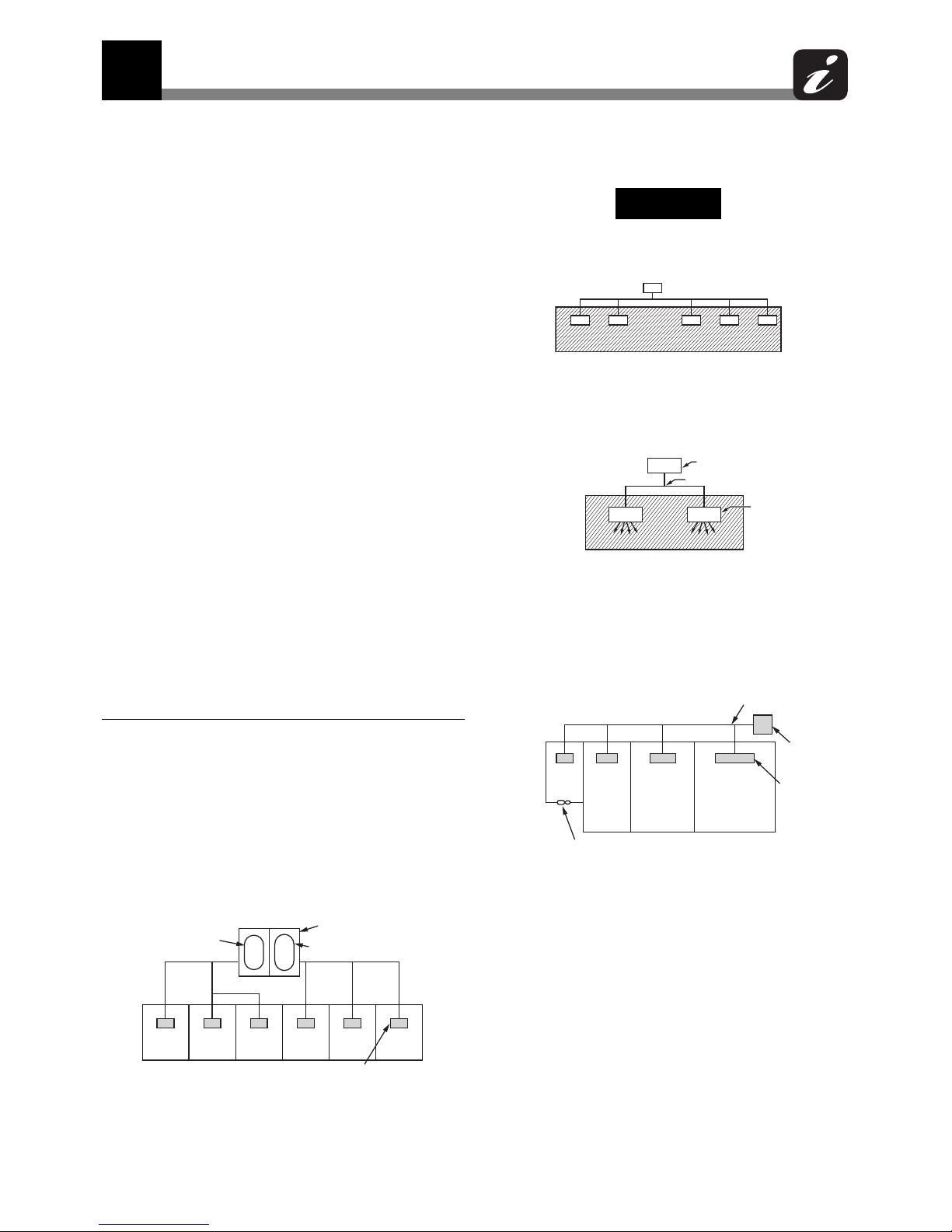
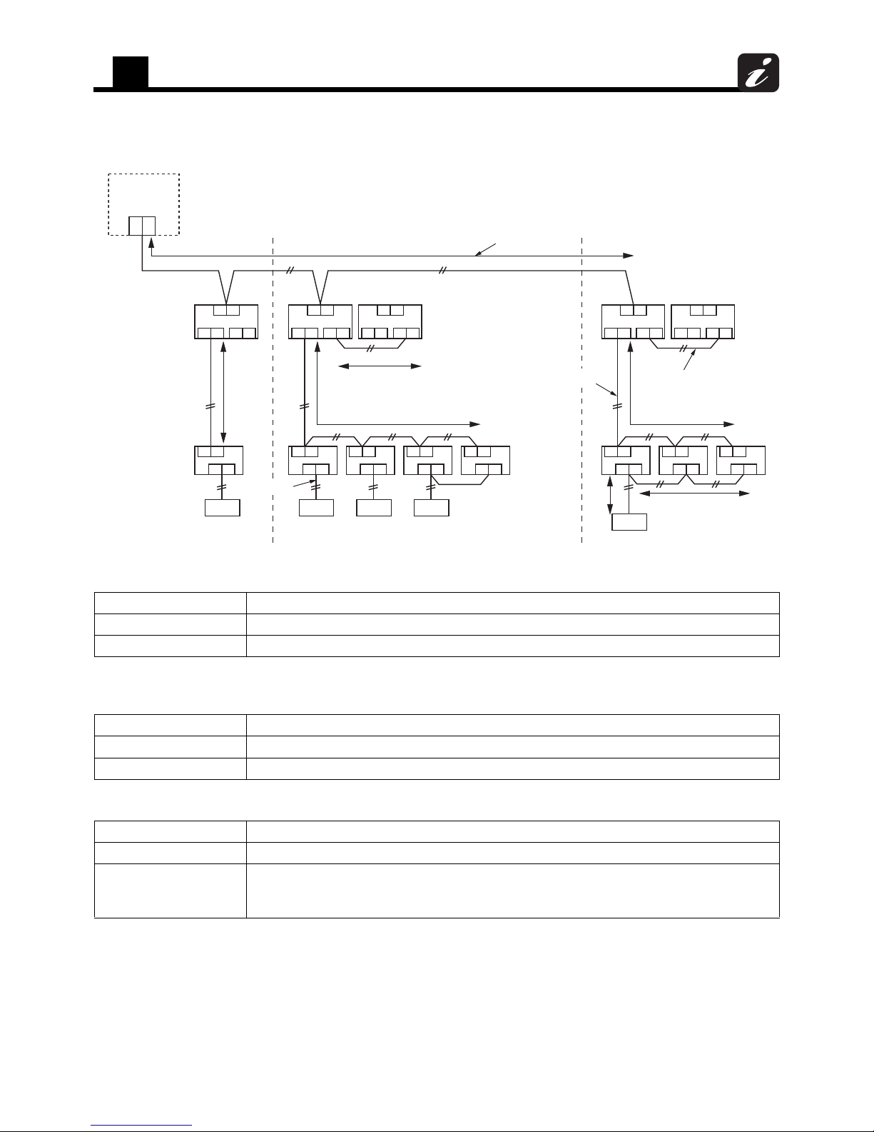
NOTE 1 :
If there are 2 or more refrigerating systems in a single
refrigerating device, the amounts of refrigerant should
be as charged in each independent device.
For the amount of charge in this example:
The possible amount of leaked refrigerant gas in
rooms A, B and C is 22 lbs (10 kg).
The possible amount of leaked refrigerant gas in
rooms D, E and F is 33 lbs (15 kg).
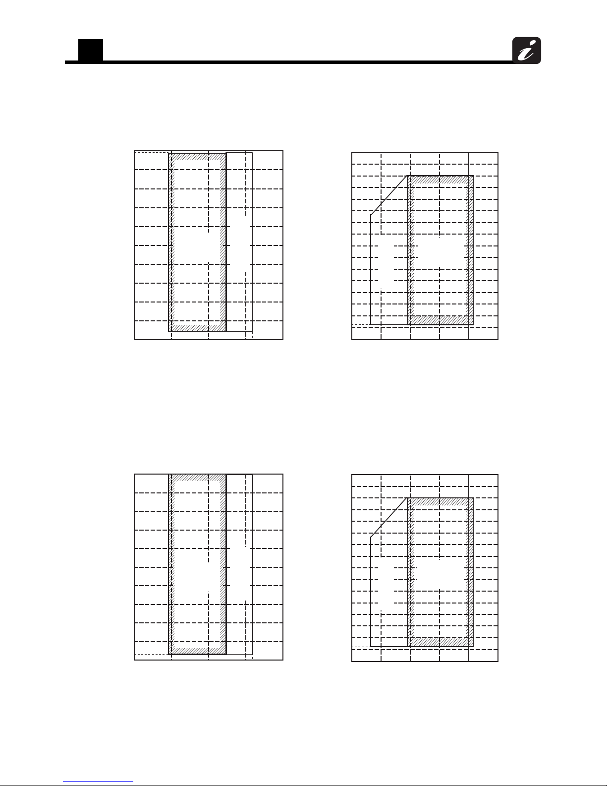
NOTE 2 :
The standards for minimum room volume are as follows.
(1) No partition (shaded portion)
(2) When there is an effective opening with the adjacent
room for ventilation of leaking refrigerant gas
(opening without a door, or an opening 0.15% or
larger than the respective floor spaces at the top or
bottom of the door).
(3) If an indoor unit is installed in each partitioned room
and the refrigerant piping is interconnected, the
smallest room of course becomes the object. But
when a mechanical ventilation is installed interlocked
with a gas leakage detector in the smallest room
where the density limit is exceeded, the volume of
the next smallest room becomes the object.
Total amount of refrigerant (lbs (kg))
Min. volume of the indoor unit installed room (ft
3
(m3))
≤ Concentration limit (lbs/ft
3
(kg/m3))
Outdoor unit
e.g., charged amount
((22 lbs) 10 kg)
e.g.,charged amount
(33 lbs (15 kg))
Room A
Indoor unit
Room B Room C Room D Room E Room F
Important
Outdoor unit
Refrigerant piping
Indoor unit
Outdoor unit
Mechanical ventilation device - Gas leak detector
Indoor unit
Very
small
room
Small
room
Medium
room
Large
room
Refrigerant piping
1
System overview
3
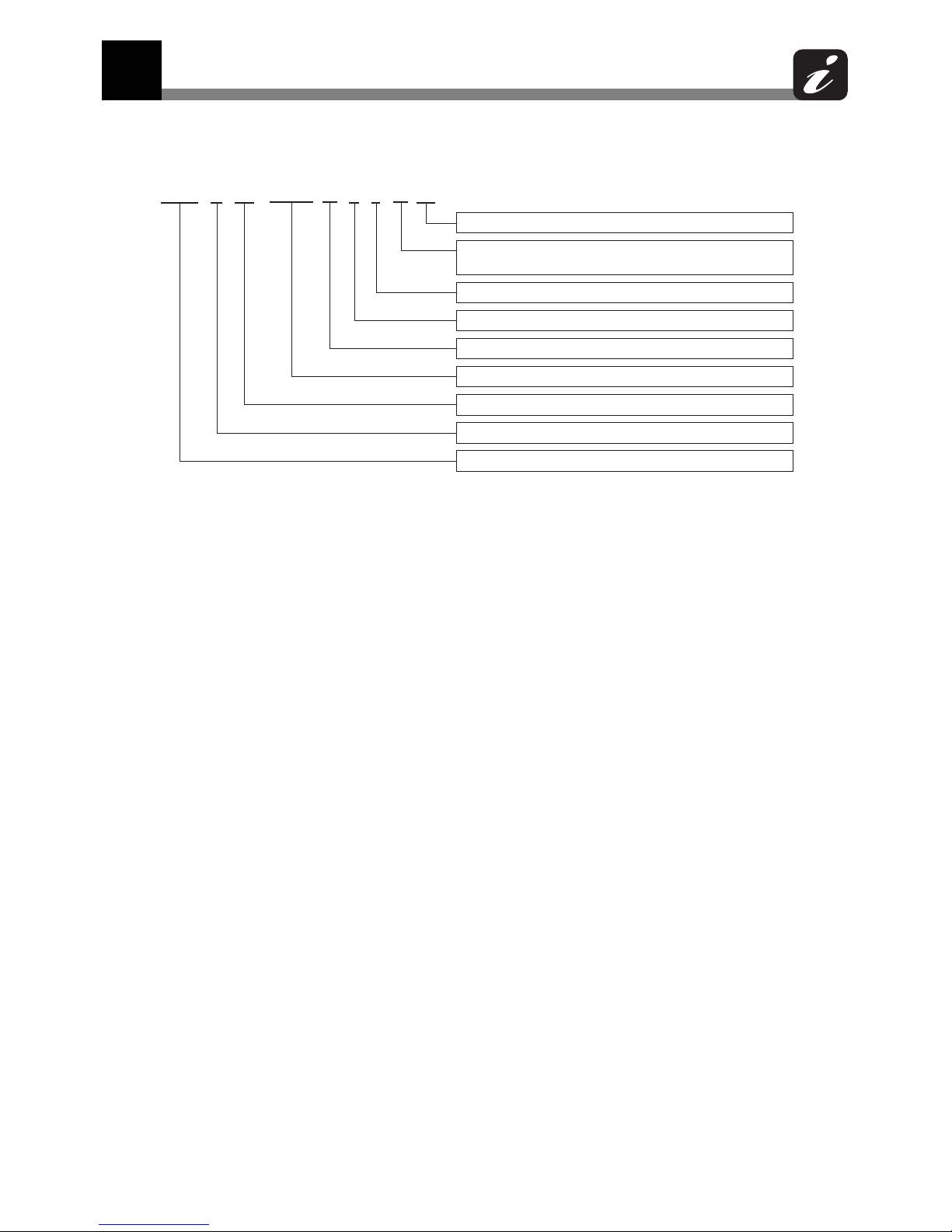
1-1. Allocation standard of model name
MMY- M AP 䕿䕿䕿䚷䕿 䚷䕿 F T UL
UL : USA, Canada
Power supply specifications, 9 : 3phase 208/230 V, 60 Hz
6 : 3phase 460 V, 60 Hz
T : Inverter Unit
F : Heat Recovery, H : Heat Pump
Development series number
Nominal cooling capacity
Refrigerant R410A
M : Single module unit, No mark : Combined Model name
Modular Multi
1 System overview
1
System overview
4
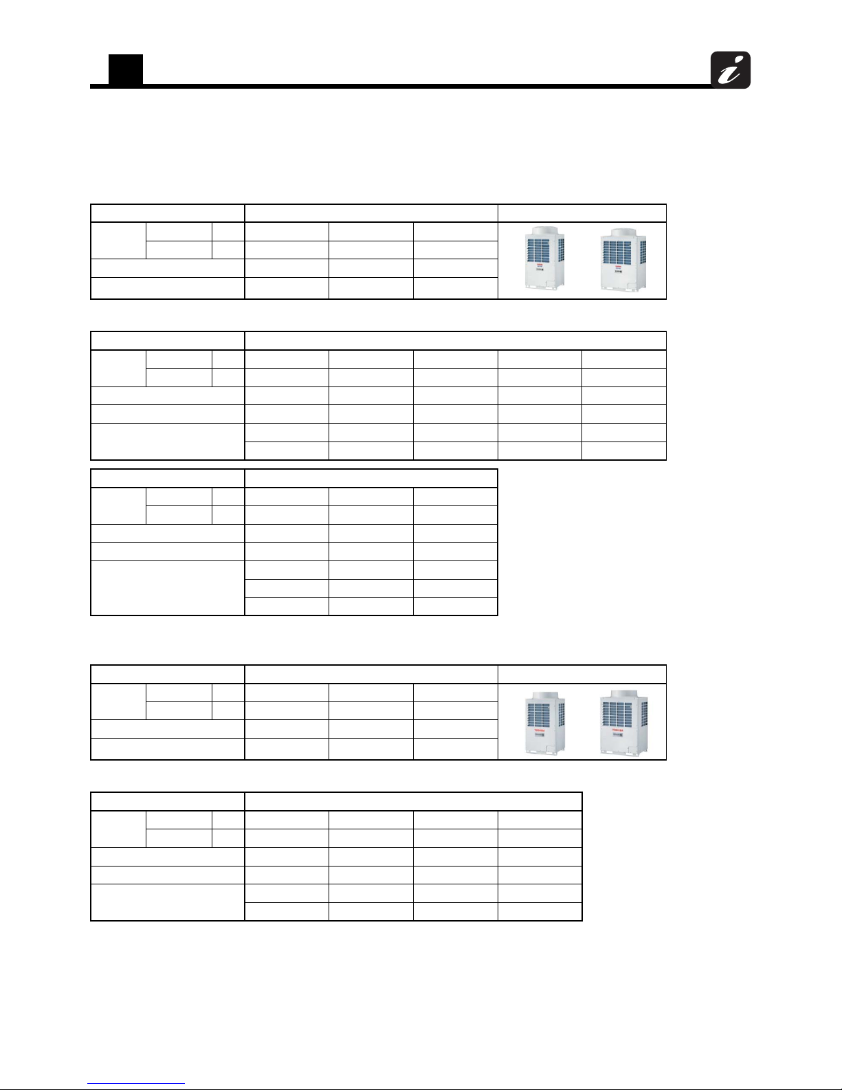
1-2. Summary of system equipments
1-2-1. Outdoor units
1-2-1-1. Heat recovery
Combination of outdoor units
1-2-1-2. Heat pump
Combination of outdoor units
Unit type Inverter unit Appearance
Model name
208/230 V, 60 Hz MMY- MAP0724FT9UL MAP0964FT9UL MAP1204FT9UL
460 V, 60 Hz MMY- MAP0724FT6UL MAP0964FT6UL MAP1204FT6UL
Capacity type 072 type 096 type 120 type
Capacity code 72 96 120
Unit type Inverter unit
Model name
208/230 V, 60 Hz MMY- AP1444FT9UL AP1684FT9UL AP1924FT9UL AP2164FT9UL AP2404FT9UL
460 V, 60 Hz MMY- AP1444FT6UL AP1684FT6UL AP1924FT6UL AP2164FT6UL AP2404FT6UL
Capacity type 144 type 168 type 192 type 216 type 240 type
Capacity code 144 168 192 216 240
Combined outdoor units
072 type 096 type 096 type 120 type 120 type
072 type 072 type 096 type 096 type 120 type
Unit type Inverter unit
Model name
208/230 V, 60 Hz MMY- AP2884FT9UL AP3124FT9UL AP3364FT9UL
460 V, 60 Hz MMY- AP2884FT6UL AP3124FT6UL AP3364FT6UL
Capacity type 288 type 312 type 336 type
Capacity code 288 312 336
Combined outdoor units
096 type 120 type 120 type
096 type 096 type 120 type
096 type 096 type 096 type
Unit type Inverter unit Appearance
Model name
208/230 V, 60 Hz MMY- MAP0724HT9UL MAP0964HT9UL MAP1144HT9UL
460 V, 60 Hz MMY- MAP0724HT6UL MAP0964HT6UL MAP1144HT6UL
Capacity type 072 type 096 type 114 type
Capacity code 72 96 114
Unit type Inverter unit
Model name
208/230 V, 60 Hz MMY- AP1444HT9UL AP1684HT9UL AP1924HT9UL AP2284HT9UL
460 V, 60 Hz MMY- AP1444HT6UL AP1684HT6UL AP1924HT6UL AP2284HT6UL
Capacity type 144 type 168 type 192 type 228 type
Capacity code 144 168 192 228
Combined outdoor units
072 type 096 type 096 type 114 type
072 type 072 type 096 type 114 type
1
System overview
5
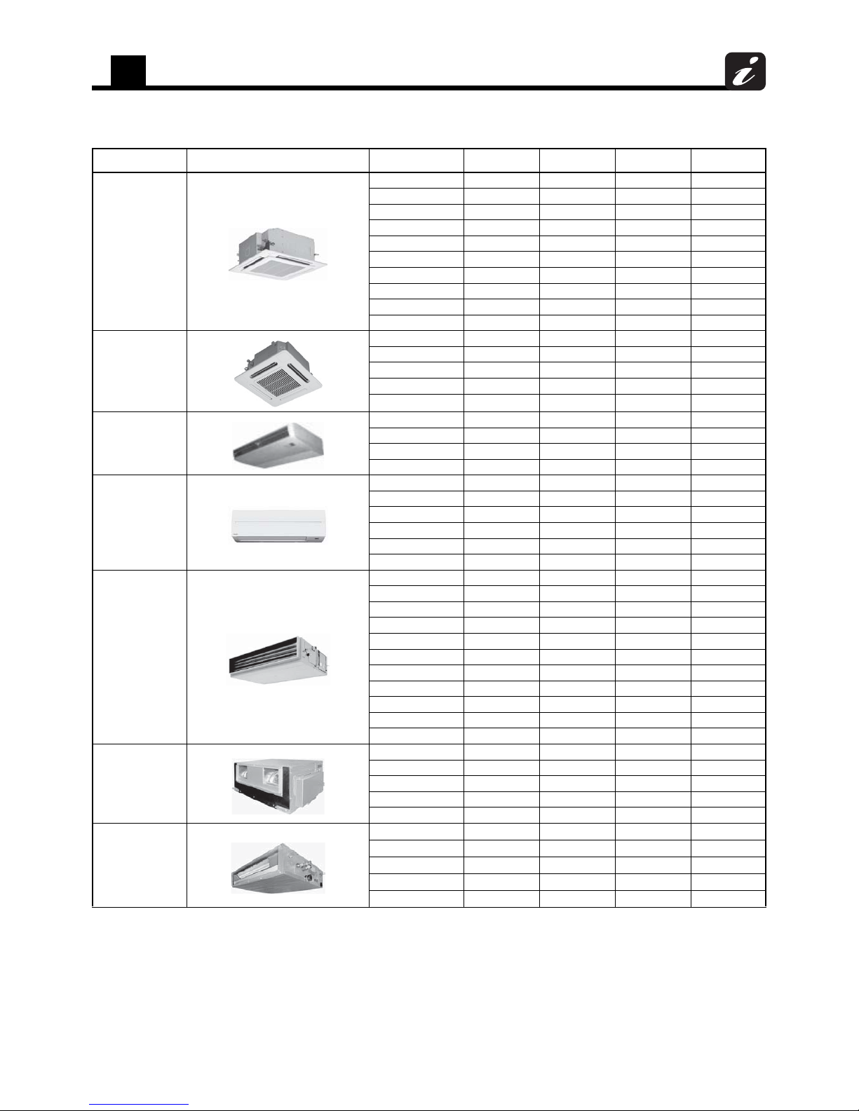
1-2-2. Indoor unit
Type Appearance Model name Capacity type Capacity code
Cooling capacity
(kBtu/h)
Heating capacity
(kBtu/h)
4-Way Cassette type
MMU-AP0072H2UL 007 type 7.5 7.5 8.5
MMU-AP0092H2UL 009 type 9.5 9.5 10.5
MMU-AP0122H2UL 012 type 12 12 13.5
MMU-AP0152H2UL 015 type 15.4 15.4 17
MMU-AP0182H2UL 018 type 18 18 20
MMU-AP0212H2UL 021 type 21 21 24
MMU-AP0242H2UL 024 type 24 24 27
MMU-AP0302H2UL 030 type 30 30 34
MMU-AP0362H2UL 036 type 36 36 40
MMU-AP0422H2UL 042 type 42 42 47.5
Compact 4-Way
Cassette type
MMU-AP0071MH2UL 007 type 7.5 7.5 8.5
MMU-AP0091MH2UL 009 type 9.5 9.5 10.5
MMU-AP0121MH2UL 012 type 12 12 13.5
MMU-AP0151MH2UL 015 type 15.4 15.4 17
MMU-AP0181MH2UL 018 type 18 18 20
Ceiling type
MMC-AP0181H2UL 018 type 18 18 20
MMC-AP0241H2UL 024 type 24 24 27
MMC-AP0361H2UL 036 type 36 36 40
MMC-AP0421H2UL 042 type 42 42 47.5
High Wall type
MMK-AP0073H2UL 007 type 7.5 7.5 8.5
MMK-AP0093H2UL 009 type 9.5 9.5 10.5
MMK-AP0123H2UL 012 type 12 12 13.5
MMK-AP0153H2UL 015 type 15.4 15.4 17
MMK-AP0183H2UL 018 type 18 18 20
MMK-AP0243H2UL 024 type 24 24 27
Medium Static Ducted
type
MMD-AP0074BH2UL 007 type 7.5 7.5 8.5
MMD-AP0094BH2UL 009 type 9.5 9.5 10.5
MMD-AP0124BH2UL 012 type 12 12 13.5
MMD-AP0154BH2UL 015 type 15.4 15.4 17
MMD-AP0184BH2UL 018 type 18 18 20
MMD-AP0214BH2UL 021 type 21 21 24
MMD-AP0244BH2UL 024 type 24 24 27
MMD-AP0304BH2UL 030 type 30 30 34
MMD-AP0364BH2UL 036 type 36 36 40
MMD-AP0424BH2UL 042 type 42 42 47.5
MMD-AP0484BH2UL 048 type 48 48 54
High Static Ducted type
MMD-AP0304H2UL 030 type 30 30 34
MMD-AP0364H2UL 036 type 36 36 40
MMD-AP0484H2UL 048 type 48 48 54
MMD-AP0724H2UL 072 type 72 72 81
MMD-AP0964H2UL 096 type 96 96 108
Slim Ducted type
MMD-AP0074SPH2UL 007 type 7.5 7.5 8.5
MMD-AP0094SPH2UL 009 type 9.5 9.5 10.5
MMD-AP0124SPH2UL 012 type 12 12 13.5
MMD-AP0154SPH2UL 015 type 15.4 15.4 17
MMD-AP0184SPH2UL 018 type 18 18 20
1
System overview
6
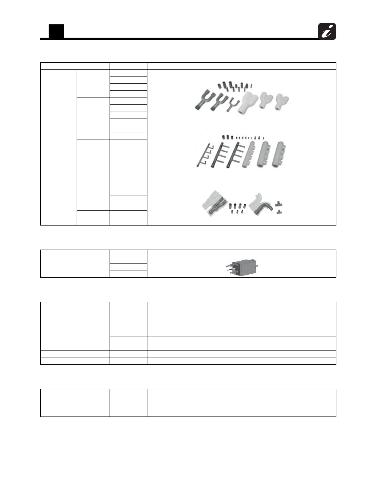
1-2-3. Branching joints and headers
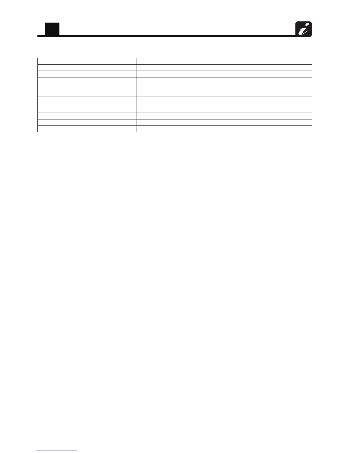
1-2-4. FS units (Flow selector units)
1-2-5. Remote control
1-2-6. Optional PCB of outdoor unit
Name Model name Appearance
Y-shape branching
joint
Heat recovery
RBM-BY55FUL
RBM-BY105FUL
RBM-BY205FUL
RBM-BY305FUL
Heat pump
RBM-BY55UL
RBM-BY105UL
RBM-BY205UL
RBM-BY305UL
4-branching header
Heat recovery
RBM-HY1043FUL
RBM-HY2043FUL
Heat pump
RBM-HY1043UL
RBM-HY2043UL
8-branching header
Heat recovery
RBM-HY1083FUL
RBM-HY2083FUL
Heat pump
RBM-HY1083UL
RBM-HY2083UL
Branching joint for
connection of outdoor
units
Heat recovery
RBM-BT14FUL
RBM-BT24FUL
Heat pump RBM-BT14UL
Name Model name Appearance
FS unit
RBM-Y0383FUL
RBM-Y0613FUL
RBM-Y0963FUL
Name Model name Remarks
Wired remote control RBC-AMT32UL
Lite-Vision plus remote control RBC-AMS51E-ES
Simple wired remote control RBC-AS41UL
Wireless remote control kit
RBC-AX32U(W)-UL For 4-Way Cassette type
RBC-AX33C-UL For Ceiling type
TCB-AX32UL For Compact 4-Way Cassette type, Medium Static Ducted type, Slim Ducted type
Central remote control BMS-CM1281TLUL
Wired remote control with weekly timer RBC-AMS41UL
Name Model name Remarks
Power peak-cut control board TCB-PCDM4UL Power peak-cut control
External master ON/OFF control boar d TCB-PCMO4UL Extern al master ON/OFF control, Night operation control, Oper ation mode selection control, Snowfall fan control
Output control board TCB-PCIN4UL Error / operation output control, Compressor operation output, Operating rate output
1
System overview
7
1-2-7. Controls
Name Model name Remarks
Remote location ON/OFF Control Box TCB-IFCB-4UL
“1:1 model" Connection Interface TCB-PCNT31TLUL Link adapter for "1:1 model" to enable connection to VRF system network.
LonWorks LN Interface TCB-IFLN642TLUL
Smart BMS manager BMS-SM1280HTLUL
Energy Monitoring Relay Interface BMS-IFWH5UL
Digital I/O Relay Interface BMS-IFDD03UL
BACnet Server
BMS-LSV6UL
BMS-STBN09UL
TCS-NET Relay Interface BMS-IFLSV4UL
Touch Screen Controller BMS-CT5120UL
BMS-IFBN640TLUL
BN Interface
2
Equipment selection procedure
8
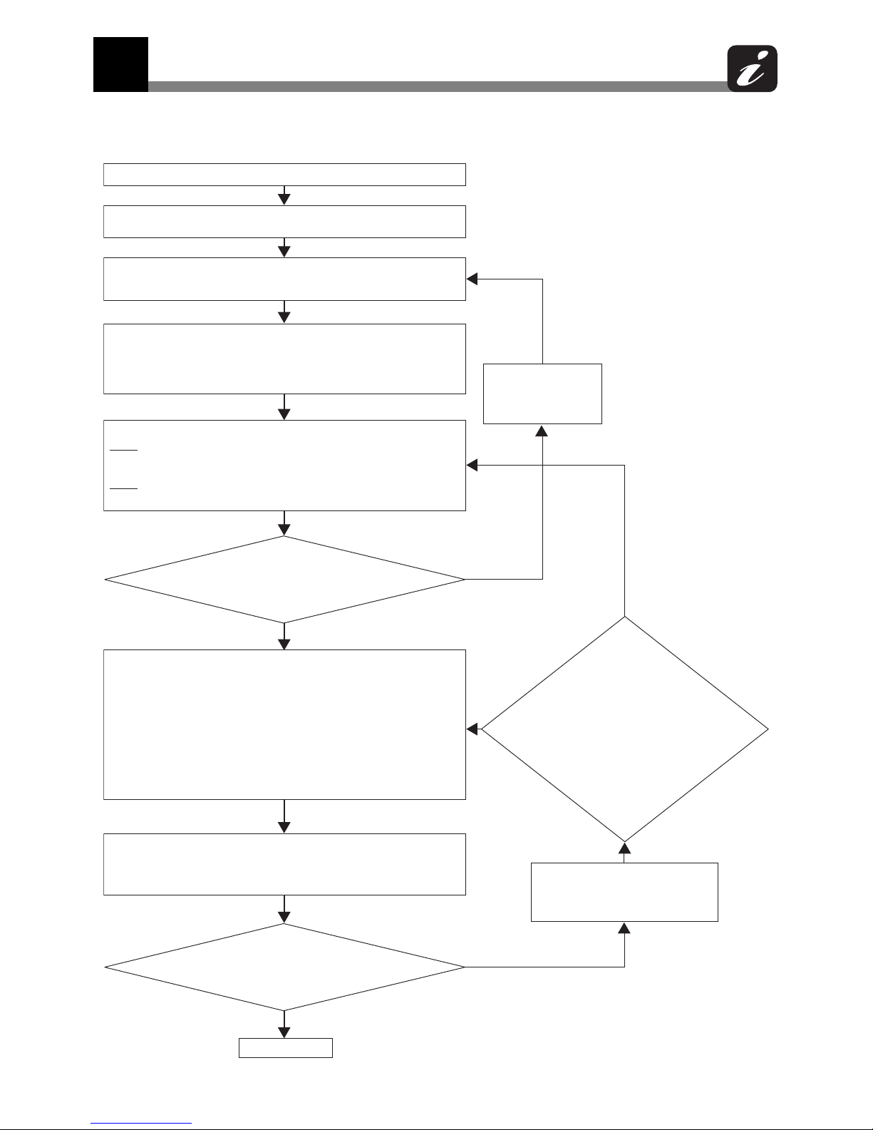
2-1. Selection flow chart
(1) Determination of indoor air-conditioning load at each room.
(2) Preliminary selection of indoor units in the standard capacity no less
than air-conditioning load at each room.
(3) Calculate corrected capacity A of each indoor unit by correcting of
indoor temperature for the standard capacity of each indoor unit.
([Chart 1])
(4) Preliminary selection of outdoor unit in the standard capacity no less
than total values of corrected capacity A in indoor units. At the same time,
check both connectable indoor units number and the outdoor unit
diversity(Connected ratio of indoor units to outdoor units) for the
specifications.
(5) Calculate corrected capacity B of each indoor unit by following 2 steps.
Step1:Find the correction value of "Connecting pipe length and lift" by
both the longest length and the largest height with selected piping
condition at (4) or (4)'. ([Chart 3])
Step2:Calculate capacity B by multiplying the value of step1 by corrected
capacity A.
(6) Corrected capacity B of indoor
unit >= air-conditioning load (for All
rooms)
(9) Corrected capacity C of indoor
unit >= air-conditioning load (for All
rooms)
(7) Find correction values of below items for the standard capacity of
outdoor unit selected at (4) or (4)'.
Then determination of total corrected capacity of the selected outdoor unit
by all multiplying.
-Correction of indoor temperature condition ([Chart 1])
-Correction of outdoor temperature condition ([Chart 2])
-Correction of connecting pipe length and lift between indoor and outdoor
units by both the longest length and the largest height ([Chart 3])
-Correction of outdoor unit diversity in only over 100 % ([Chart 4])
-Correction of frost condition on outdoor heat exchanger when in heating
([Chart 5])
(8) Calculate corrected capacity C of each indoor unit by multiplying the
total corrected capacity of outdoor unit at (7) by proportional division of
each indoor unit standard capacity for total standard capacity of all indoor
units.
end
(4)' Increase of outdoor unit capacity.
At the same time, check both
connectable indoor units number
and the outdoor unit diversity
(5)' <Only cooling>
The correction characteristic
of "connecting pipe length and
lift" ([Chart 3]) between
increased outdoor unit at (4)'
and preliminary selected
outdoor unit at (4) is different.
(The both graphs are
different.)
(2)' Increase of indoor
unit capacity at object
room against airconditioning load
NO
NO
NO
YES
YES
YES
2 Equipment selection procedure
2
Equipment selection procedure
9
2-2. Combination conditions for indoor unit and
outdoor unit
2-2-1. The capacity code for indoor unit, the capacity code is decided for each capacity rank.
2-2-2. The capacity codes of outdoor units are decided at each capacity type. The maximum number of connectable
indoor units and the total value of capacity codes of the indoor units are also decided.
NOTE
Compared with the capacity code of the outdoor unit, the total value of capacity codes of the connectable indoor
units differs based on the height difference between the indoor units.
When the height difference between the indoor units is 49 ft (15 m) or less
If “Medium Static Ducted Type (MMD-AP***BH)” is excluded in the system: Total indoor capacity code must be
between 80% and 125% of the capacity of the outdoor unit.
Total indoor capacity code must be between 80% and 120% of the capacity of the outdoor unit.
If “one of 007, 009 or 012 of 4-way Air Discharge Cassette type (MMU-AP***H*)” is included in the system:
Total indoor capacity code must be 80% - 105%.
When the height difference between the indoor units is over 49 ft (15 m)
Total indoor unit capacity code (Equivalent to Capacity) must be between 80% and 105% of the capacity of the
outdoor unit.
If “one of 007, 009 or 012 of 4-way Air Discharge Cassette type (MMU-AP***H*)” is included in the system:
Total indoor capacity code must be 80% - 105%.
Capacity rank type 007 009 012 015 018 021 024 027 030 036 042 048 054 072 096
Capacity code
(Equivalent to capacity)
7.5 9.5 12 15.4 18 21 24 27 30 36 42 48 54 72 96
System Outdoor unit
capacity
type
Outdoor
capacity code
(Equivalent to
capacity)
Maximum number of indoor units
If “Medium Static Ducted Type
(MMD-AP***BH)” is excluded in
the system
If “Medium Static Ducted Type
(MMD-AP***BH)” is included in
the system
Height difference between
indoor units
Height difference between
indoor units
49 ft (15 m) or
less
Over 49 ft (15 m) 49 ft (15 m) or
less
Over 49 ft (15 m)
Heat
recovery
072 type 72 12 10 11 10
096 type 96 16 13 15 13
120 type 120 20 16 19 16
144 type 144 24 20 23 20
168 type 168 28 23 26 23
192 type 192 32 26 30 26
216 type 216 36 30 34 30
240 type 240 40 33 38 33
288 type 288 48 40 46 40
312 type 312 48 43 48 43
336 type 336 48 47 48 47
Heat
pump
072 type 72 12 10 11 10
096 type 96 16 13 15 13
114 type11419151815
144 type 144 24 20 23 20
168 type 168 28 23 26 23
192 type 192 32 26 30 26
228 type 228 38 31 36 31
2
Equipment selection procedure
10
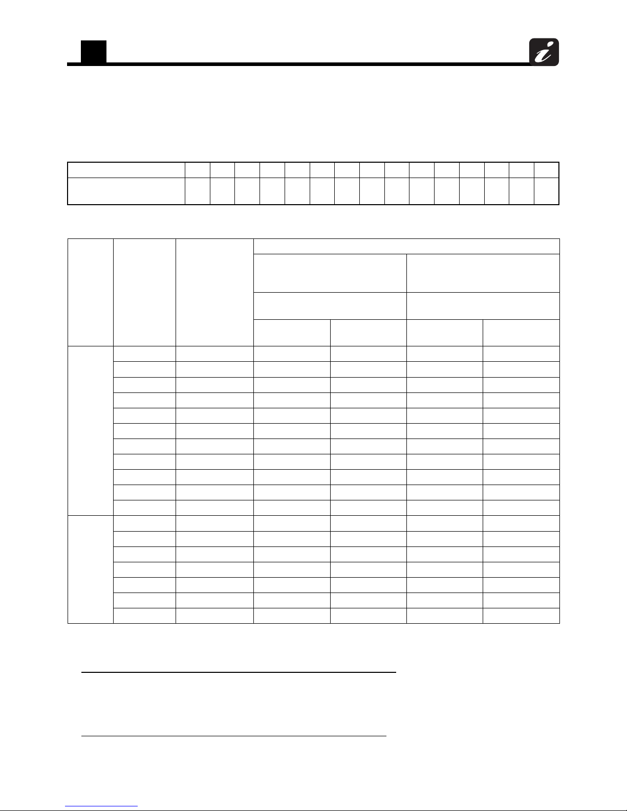
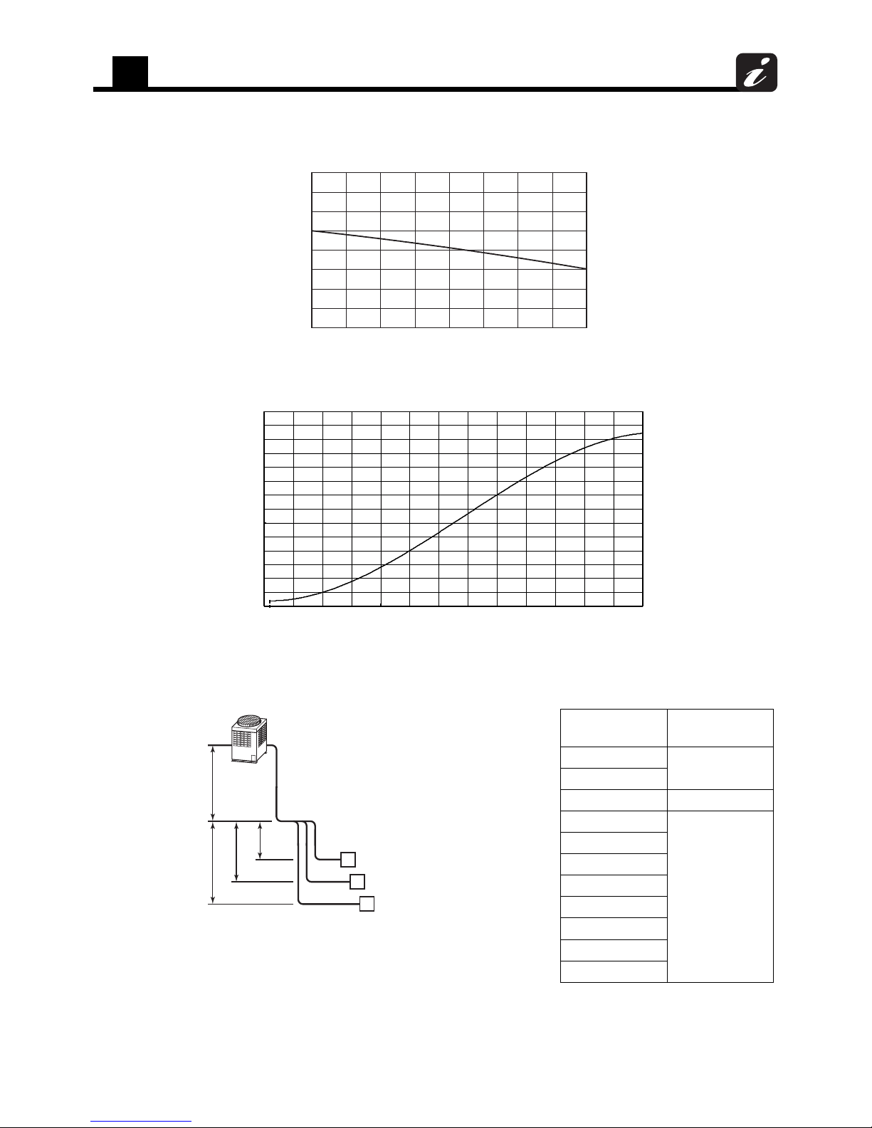
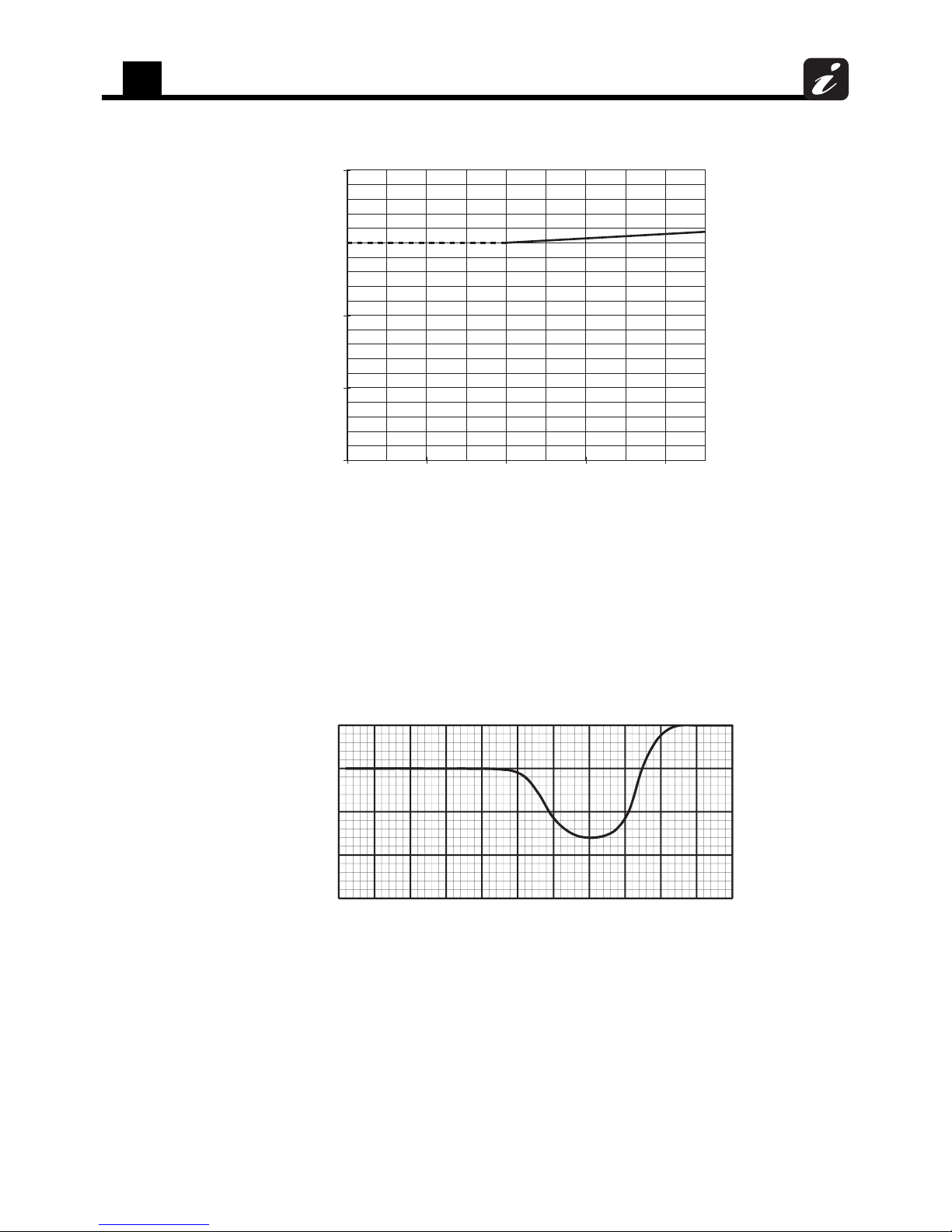
2-3. Cooling/heating capacity characteristics
2-3-1. Heat recovery
2-3-1-1. Correction charts for cooling capacity calculation
[Chart 1] Indoor air wet bulb temperature vs. capacity correction value
[Chart 2] Outdoor air dry bulb temperature vs. capacity correction value
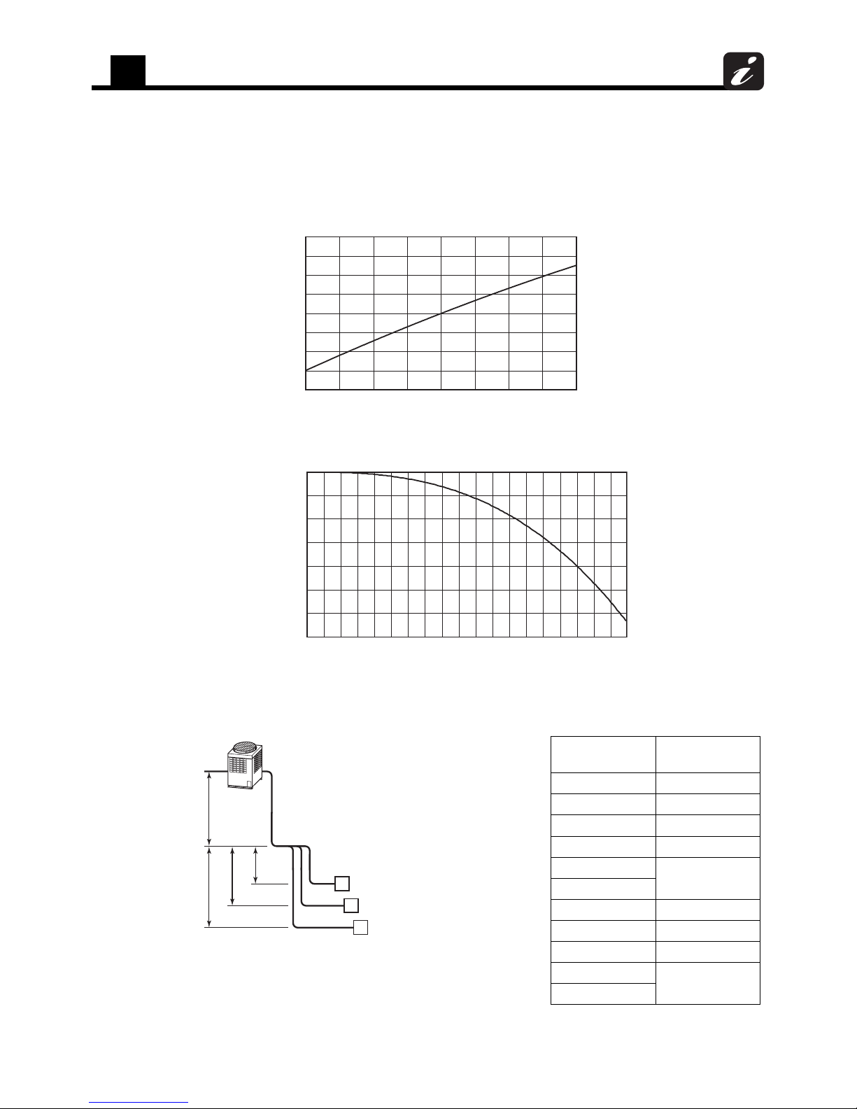
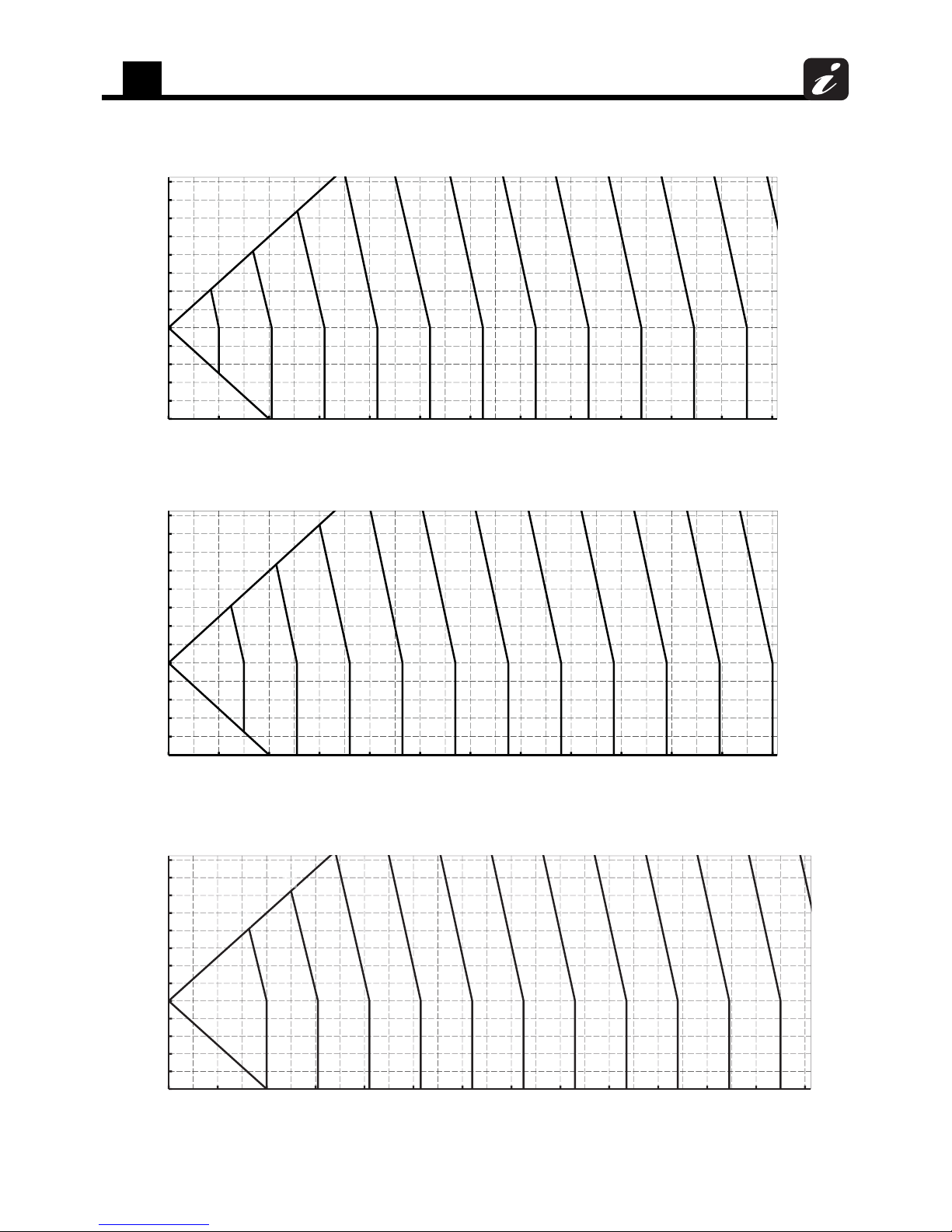
[Chart 3] Connecting pipe length and lift difference between indoor and outdoor units vs.
capacity correction value
0.8
0.9
1
1.1
1.2
59 61 63 65 67 69 71 73 75
Indoor air wet bulb temp. (°F WB)
Capacity correction value
Outdoor air dry bulb temp. (°F DB)
Capacity correction value
0.85
0.9
0.95
1
1.05
1.1
1.15
1.2
20 25 30 35 40 45 50 55 60 65 70 75 80 85 90 95 100 10514
Outdoor unit
Indoor unit
L is the longest one of (lo + la, lo + lb, lo + lc)
H = ho + (Largest one of ha, hb, and hc)
A
ha
hb
hc
ho lo
la
lb
lc
B
C
Outdoor unit
capacity type
Graph
072 A1
096 B1
120 A2
144 A3
168
B2
192
216 A3
240 B2
288 A3
312
B2
336
2
Equipment selection procedure
11
Outdoor unit (A1)
indoor and outdoor units H (ft)
Lift difference height between
-100
-80
-60
-40
-20
0
20
40
60
80
100
120
140
160
0 50 100 150 200 250 300 350 400 450 500 550 600
Piping equivalent length (ft)
1.0
0.95
0.90
0.875
0.85
0.825
0.80
0.775
0.75
0.925
0.975
indoor and outdoor units H (ft)
Outdoor unit (A2)
Lift difference height between
-80
-60
-40
-20
0
20
40
60
80
100
120
140
160
0 50 100 150 200 250 300 350 400 450 500 550 600
Piping equivalent length (ft)
1.0
0.975
0.90
0.875
0.85
0.825
0.80
0.775
0.925
- 100
0.95
Outdoor unit (A3)
-100
-80
-60
-40
-20
0
20
40
60
80
100
120
140
160
0 50 100 150 200 250 300 350 400 450 500 550 600 650
Lift difference height between
indoor and outdoor units H (ft)
Piping equivalent length (ft)
0.95
0.90
0.875
0.85
0.825
0.80
0.775
0.75
0.925
0.975
1.0
2
Equipment selection procedure
12
[Chart 4]* Correction of outdoor unit diversity
* Coefficient to use for the correction of the outdoor unit capacity when the total capacity of the indoor units are not
equal to the outdoor unit capacity.
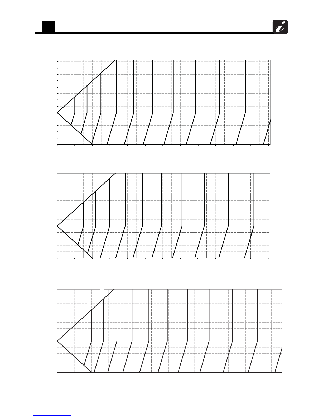
Outdoor unit (B1)
indoor and outdoor units H (ft)
Lift difference height between
-80
-60
-40
-20
0
20
40
60
80
100
120
140
160
0 50 100 150 200 250 300 350 400 450 500 550 600
Piping equivalent length (ft)
1.0
0.95
0.90
0.875
0.85
0.825
0.80
0.775
0.725
0.75
0.925
0.975
- 100
Outdoor unit (B2)
-100
-80
-60
-40
-20
0
20
40
60
80
100
120
140
160
0 50 100 150 200 250 300 350 400 450 500 550 600 650
Lift difference height between
indoor and outdoor units H (ft)
Piping equivalent length (ft)
1.0
0.95
0.90
0.875
0.85
0.825
0.80
0.775
0.75
0.925
0.975
0.725
0.7
0.8
0.9
1
1.1
80 90 100 110 120
Indoor units total capacity ratio (%)
Capacity correction value
2
Equipment selection procedure
13
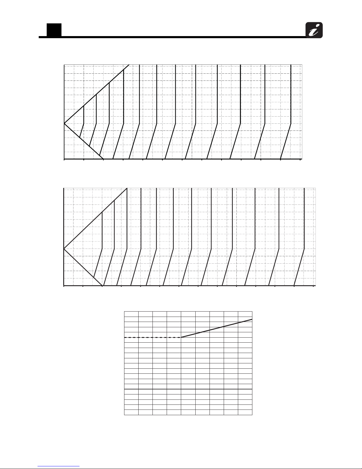
2-3-1-2. Correction charts for heating capacity calculation
[Chart 1] Indoor air dry bulb temperature vs. capacity correction value
[Chart 2] Outdoor air wet bulb temperature vs. capacity correction value
[Chart 3] Connecting pipe length and lift difference between indoor and outdoor units vs.
capacity correction value
0.8
0.9
1
1.1
1.2
61 63 65 67 69 71 73 75 77
Indoor air dry bulb temp. (°F DB)
Capacity correction value
0.50
0.55
0.60
0.65
0.70
0.75
0.80
0.85
0.90
0.95
1.00
1.05
1.10
1.15
1.20
-5 0 5 10 15 20 25 30 35 40 45 50 55 60
Capacity correction value
Outdoor ai r wet bulb temp. ( °F WB)
-
4
Outdoor unit
capacity type
Graph
072
X
096
120 Y
144
Z
168
192
216
240
288
312
336
Outdoor unit
Indoor unit
L is the longest one of (lo + la, lo + lb, lo + lc)
H = ho + (Largest one of ha, hb, and hc)
A
ha
hb
hc
ho lo
la
lb
lc
B
C
2
Equipment selection procedure
14
Outdoor unit (X)
indoor and outdoor units H (ft)
Lift difference height between
-100
-80
-60
-40
-20
0
20
40
60
80
100
120
140
160
0 50 100 150 200 250 300 350 400 450 500 550 600
Piping equivalent length (ft)
1.00
0.99
0.98
0.97
0.96
0.95
0.94
0.93
0.92
0.91
0.90
0.89
Outdoor unit (Y)
indoor and outdoor units H (ft)
Lift difference height between
-100
-80
-60
-40
-20
0
20
40
60
80
100
120
140
160
0 50 100 150 200 250 300 350 400 450 500 550 600
Piping equivalent length (ft)
1.00
0.99
0.98
0.97
0.96
0.95
0.94
0.93
0.92
0.91
0.90
Outdoor unit (Z)
-100
-80
-60
-40
-20
0
20
40
60
80
100
120
140
160
0 50 100 150 200 250 300 350 400 450 500 550 600 650
Lift difference height between
indoor and outdoor units H (ft)
Piping equivalent length (ft)
1.0
0.99
0.98
0.97
0.96
0.95
0.94
0.93
0.92
0.91
0.90
0.89
2
Equipment selection procedure
15
[Chart 4]* Correction of outdoor unit diversity
* Coefficient to use for the correction of the outdoor unit capacity when the total capacity of the indoor units are not
equal to the outdoor unit capacity.
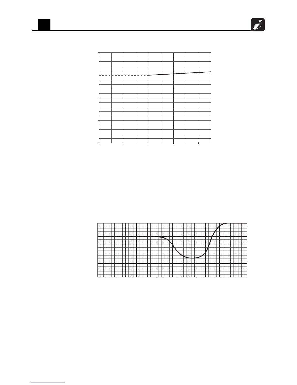
2-3-1-3. Capacity correction in case of frost on the outdoor heat exchanger when in
heating
Correct the heating capacity when frost can be found on the outdoor heat exchanger.
Heating capacity =Capacity after correction of outdoor unit x Correction value of capacity resulted from
frost (Capacity after correction of outdoor unit: Heating capacity calculated in the
above item 2.)
[Chart 5] Capacity correction in case of frost on the outdoor heat exchanger
2-3-1-4. Rated conditions
Cooling: Indoor air temperature 80 °F DryBulb/67 °F WetBulb, Outdoor air temperature 95 °F DryBulb
Heating: Indoor air temperature 70 °F DryBulb, Outdoor air temperature 47 °F DryBulb/43 °F WetBulb
0.7
0.8
0.9
1
1.1
80 90 100 110 120
Indoor units total capacity ratio (%)
Capacity correction value
Outdoor air wet bulb temp. (°F WB)
Capacity correction value
0.8
0.85
0.9
0.95
1
-4 0 5 10 15 20 25 30 35 40 45 50

2
Equipment selection procedure
16
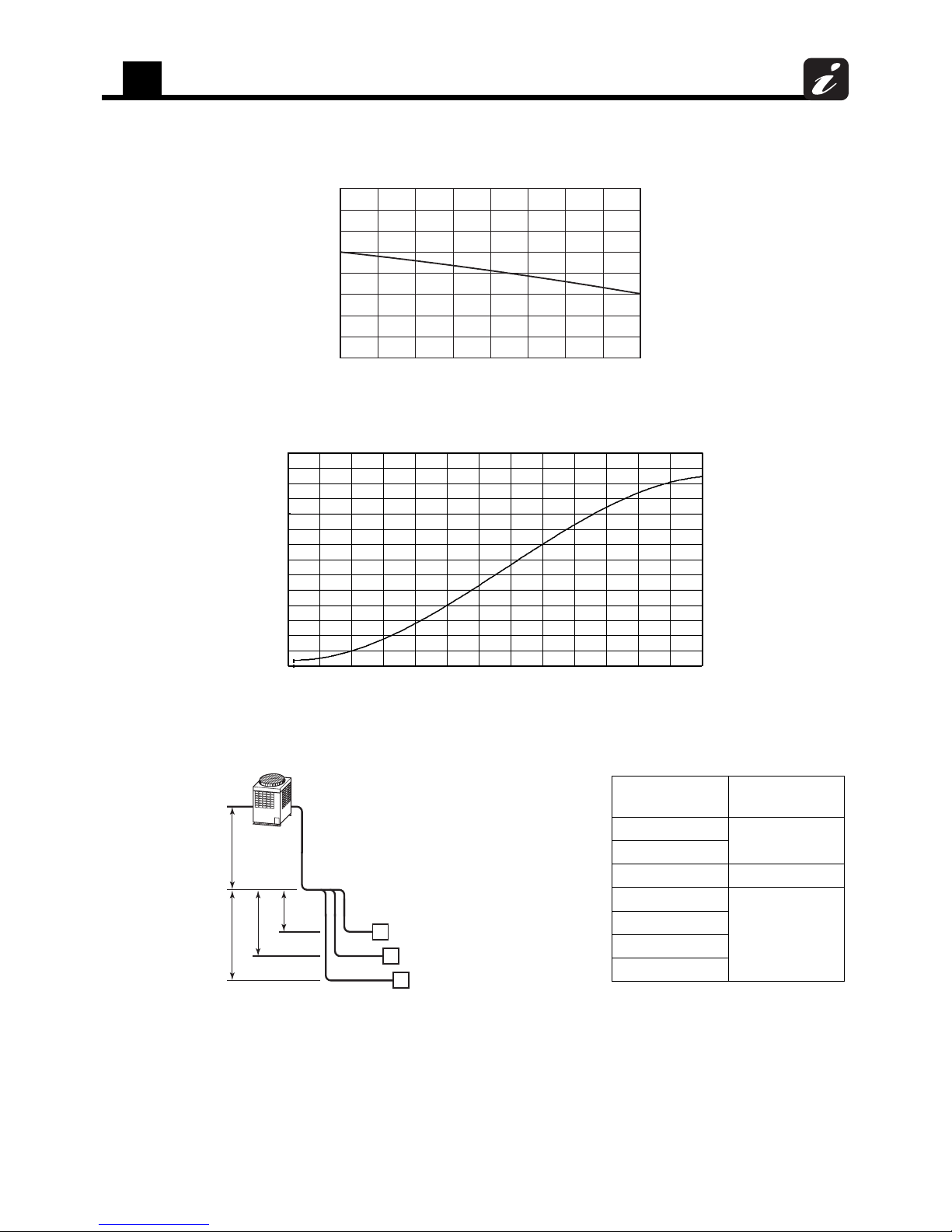
2-3-2. Heat pump
2-3-2-1. Correction charts for cooling capacity calculation
[Chart 1] Indoor air wet bulb temperature vs. capacity correction value
[Chart 2] Outdoor air dry bulb temperature vs. capacity correction value
[Chart 3] Connecting pipe length and lift difference between indoor and outdoor units vs.
capacity correction value
0.8
0.9
1
1.1
1.2
59 61 63 65 67 69 71 73 75
Indoor air wet bulb temp. (°F WB)
Capacity correction value
0.8
0.85
0.9
0.95
1
1.05
1.1
1.15
1.2
25 30 35 40 45 50 55 60 65 70 75 80 85 90 95 100 105 110 115
Capacity correction value
Outdoor air dry bulb temp. (°F DB)
Outdoor unit
Indoor unit
L is the longest one of (lo + la, lo + lb, lo + lc)
H = ho + (Largest one of ha, hb, and hc)
A
ha
hb
hc
ho lo
la
lb
lc
B
C
Outdoor unit
capacity type
Graph
072 A1
096 B1
114 A2
144 A3
168
B2
192
228 A3

2
Equipment selection procedure
17
Outdoor unit (A1)
Piping equivalent length (ft)
indoor and outdoor units H (ft)
0.875
0.85
0.825
0.80
0.775
0.725
0.75
1.0
0.95
0.90
0.925
0.975
0 50 100 150 200 250 300 350 400 450 500 550 600 650
Lift difference height between
-120
-100
-80
-60
-40
-20
0
20
40
60
80
100
120
140
160
180
200
220
0 50 100 150 200 250 300 350 400 450 500 550 600 650
indoor and outdoor units H (ft)
1.0
0.975
0.90
0.875
0.85
0.825
0.80
0.775
0.725
0.75
0.925
0.95
Piping equivalent length (ft)
Outdoor unit (A2)
Lift difference height between
-120
-100
-80
-60
-40
-20
20
40
60
80
100
120
140
160
180
200
220
0
0 50 100 150 200 250 300 350 400 450 500 550 600 650 700
Outdoor unit (A3)
Piping equivalent length (ft)
indoor and outdoor units H (ft)
0.90
0.875
0.85
0.825
0.80
0.775
0.75
1.0
0.95
0.975
0.925
Lift difference height between
-120
-100
-80
-60
-40
-20
0
20
40
60
80
100
120
140
160
180
200
220

2
Equipment selection procedure
18
[Chart 4]* Correction of outdoor unit diversity
* Coefficient to use for the correction of the outdoor unit capacity when the total capacity of the indoor units are not
equal to the outdoor unit capacity.
Outdoor unit (B1)
Piping equivalent length (ft)
indoor and outdoor units H (ft)
0.875
0.85
0.825
0.80
0.775
0.725
0.75
0.70
0.675
1.0
0.95
0.90
0.925
0.975
0 50 100 150 200 250 300 350 400 450 500 550 600 650
Lift difference height between
-120
-100
-80
-60
-40
-20
0
20
40
60
80
100
120
140
160
180
200
220
0 50 100 150 200 250 300 350 400 450 500 550 600 650 700
Outdoor unit (B2)
Piping equivalent length (ft)
indoor and outdoor units H (ft)
0.90
0.875
0.85
0.825
0.80
0.775
0.70
0.75
0.725
1.0
0.95
0.925
0.975
Lift difference height between
-120
-100
-80
-60
-40
-20
0
20
40
60
80
100
120
140
160
180
200
220
0.7
0.8
0.9
1
1.1
80 90 100 110 120
Indoor units total capacity ratio (%)
Capacity correction value
2
Equipment selection procedure
19
2-3-2-2. Correction charts for heating capacity calculation
[Chart 1] Indoor air dry bulb temperature vs. capacity correction value
[Chart 2] Outdoor air wet bulb temperature vs. capacity correction value
[Chart 3] Connecting pipe length and lift difference between indoor and outdoor units vs.
capacity correction value
0.8
0.9
1
1.1
1.2
61 63 65 67 69 71 73 75 77
Indoor air dry bulb temp. (°F DB)
Capacity correction value
0.50
0.55
0.60
0.65
0.70
0.75
0.80
0.85
0.90
0.95
1.00
1.05
1.10
1.15
1.20
-5 0 5 10 15 20 25 30 35 40 45 50 55 60
Capacity correction value
Outdoor ai r wet bulb temp. ( °F WB)
-
4
Outdoor unit
capacity type
Graph
072
X
096
114 Y
144
Z
168
192
228
Outdoor unit
Indoor unit
L is the longest one of (lo + la, lo + lb, lo + lc)
H = ho + (Largest one of ha, hb, and hc)
A
ha
hb
hc
ho lo
la
lb
lc
B
C

2
Equipment selection procedure
20
Outdoor unit (X)
Piping equivalent length (ft)
indoor and outdoor units H (ft)
1.00
0.99
0.98
0.97
0.96
0.95
0.94
0.93
0.92
0.91
0.90
0.89
0.88
0.87
0 50 100 150 200 250 300 350 400 450 500 550 600 650
Lift difference height between
-120
-100
-80
-60
-40
-20
0
20
40
60
80
100
120
140
160
180
200
220
0 50 100 150 200 250 300 350 400 450 500 550 600 650 700
Outdoor unit (Y)
Piping equivalent length (ft)
indoor and outdoor units H (ft)
1.00
0.99
0.98
0.97
0.96
0.95
0.94
0.93
0.92
0.91
0.90
0.89
0.88
0.87
Lift difference height between
-120
-100
-80
-60
-40
-20
0
20
40
60
80
100
120
140
160
180
200
220
0 50 100 150 200 250 300 350 400 450 500 550 600 650 700
Outdoor unit (Z)
Piping equivalent length (ft)
indoor and outdoor units H (ft)
1.00
0.99
0.98
0.97
0.96
0.95
0.94
0.93
0.92
0.91
0.90
0.89
0.88
Lift difference height between
-120
-100
-80
-60
-40
-20
0
20
40
60
80
100
120
140
160
180
200
220
2
Equipment selection procedure
21
[Chart 4]* Correction of outdoor unit diversity
* Coefficient to use for the correction of the outdoor unit capacity when the total capacity of the indoor units are not
equal to the outdoor unit capacity.
2-3-2-3. Capacity correction in case of frost on the outdoor heat exchanger when in
heating
Correct the heating capacity when frost can be found on the outdoor heat exchanger.
Heating capacity =Capacity after correction of outdoor unit x Correction value of capacity resulted from
frost (Capacity after correction of outdoor unit: Heating capacity calculated in the
above item 2.)
[Chart 5] Capacity correction in case of frost on the outdoor heat exchanger
2-3-2-4. Rated conditions
Cooling: Indoor air temperature 80 °F DryBulb/67 °F WetBulb, Outdoor air temperature 95 °F DryBulb
Heating: Indoor air temperature 70 °F DryBulb, Outdoor air temperature 47 °F DryBulb/43 °F WetBulb
0.7
0.8
0.9
1
1.1
80 90 100 110 120
Indoor units total capacity ratio (%)
Capacity correction value
0.8
0.85
0.9
0.95
1
-5 0 5 10 15 20 25 30 35 40 45 50
Capacity correction value
Outdoor air wet bulb temp. (°F WB)
2
Equipment selection procedure
22
2-4. Operational temperature range
2-4-1. Heat recovery
2-4-2. Heat pump
6050
Indoor air wet bulb temp. (°F)
70 80 90
40
60
80
100
30
20
10
14
50
70
90
110
82
Continuously
operable
range
Cooling
Range for pull
down operation
Outdoor air dry bulb temp. (°F)
40 50
Indoor air dry bulb temp. (°F)
60 70 80
0
-4
-10
10
60
40
20
50
70
Continuously
operable
range
Heating
Range for warming
up operation
Outdoor air wet bulb temp. (°F)
90
30
Avoid the following place
Places where ambient temperature falls
below 5 °F for more than 72 hours running.
The outdoor heat exchanger may be
damaged by the frost.
The cooling performance may decline
considerably when total operating capacity
of cooling indoor units is less than 38 kBtu/h
while ambient temperature is below 32 °F.
40 50
Indoor air dry bulb temp. (°F)
60 70 80
0
-4
-10
10
60
40
20
50
70
Continuously
operable
range
Heating
Range for warming
up operation
Outdoor air wet bulb temp. (°F)
90
30
50 60
Indoor air wet bulb temp. (°F)
70 80 90
20
40
60
80
100
30
50
70
90
110
23
82
Continuously
operable
range
Cooling
Range for pull
down operation
Outdoor air dry bulb temp. (°F)
115
Avoid the following place
Places where ambient temperature falls
below 5 °F for more than 72 hours running.
The outdoor heat exchanger may be
damaged by the frost.
Refrigerant piping design
3
23
3 Refrigerant piping design
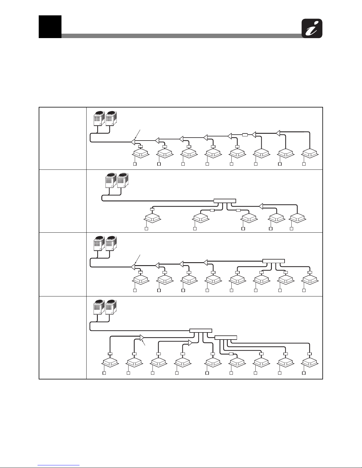
3-1. Free branching system
[1] Line branching system
[2] Header branching system
[3] Header branching system after line branching
[4] Line branching system after header branching
[5] Header branching system after header branching
The above five branching systems enable to dramatically increase the flexibility of refrigerant piping design.
Line branching
system
Header
branching
system
Line branching
system after
header
branching
Header
branching
system after
header
branching
Outdoor unit
Branching joint
Indoor unit
Remote
control
FS unit
Outdoor unit
Branching header
Indoor unit
Remote
control
FS unit
Outdoor unit
Branching joint
Indoor unit
Remote
control
Branching header
FS unit
Outdoor unit
Branching header
Indoor
unit
Remote
control
Branching
joint
FS unit
3
Refrigerant piping design
24
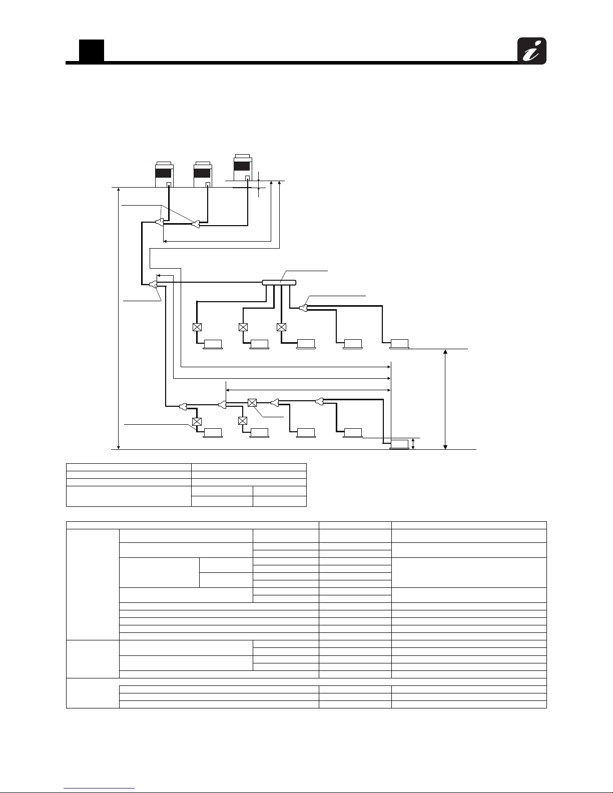
3-2. Allowable length/height difference of
refrigerant piping
3-2-1. Heat recovery
System restrictions Caution for installation
Allowable length and height difference of refrigerant piping
*1: If “Medium Static Ducted Type (MMD-AP***BH)” is included in the system: Total indoor capacity code must be between 80% and 120% of the capacity of the outdoor unit.
*2: Farthest outdoor unit from the first branching section: Follower unit (C). Farthest indoor unit from the first branching section: indoor unit (o).
*3: If FS unit is connected to multiple indoor units, connect wires of FS unit to one of the indoor unit with main remote control.
*4: Allowable values for length equivalent to furthest pipe are shown below and they vary according to capacity rank of outdoor unit.
072 to 120 type: Equivalent length 605 ft (185 m), Actual length: 540 ft (165 m)
144 to 240 type: Equivalent length 640 ft (195 m), Actual length: 575 ft (175 m)
288 to 336 type: Equivalent length 656 ft (200 m), Actual length: 591 ft (180 m)
Max. No. of combined outdoor units 3 units
Note 1)
Install the outdoor units in order of their capacity codes. A (header unit) ≥ B ≥ C
Note 2)The header unit is connected to the branching joint for outdoor unit which is
directly connected to the main pipe.
Note 3)Y-shaped branching joint must be installed horizontally.
Note 4)Make sure to connect the T-shaped branching joint of liquid pipe as <Fig1>.
Do not connect the T-shaped branching joint as <Fig2>.
Max. capacity of combined outdoor units 28 ton
Max. No. of connected indoor units 48 units
Max. capacity of combined indoor units
H2 ≤ 49 ft (15 m) 125% ( *1)
H2 > 49 ft (15 m) 105%
Allowable value (ft (m)) Pipes
Pipe length
Total extension of pipe (Liquid pipe) Actual length 985 (300)
La + Lb + Lc + LA + L1 + L2 +L3 + L4 + L5 + L6 + L7 + L8 +
a + b + c + d + e + f + g + h + i + j + k + l + m + n + o
Farthest piping length L (*2)(*4)
Equivalent length 656 (200)
Lc + LA + L1 + L3 + L4 + L5 + L6 + L7 + o
Actual length 591 (180)
Main piping length
H2 > 9.8 ft (3 m)
Equivalent length 330 (100)
L1
Actual length 280 (85)
H2 ≤ 9.8 ft (3 m)
Equivalent length 395 (120)
Actual length 330 (100)
Farthest equivalent piping length from the first
branch Li (*2)
H1 > 9.8 ft (3 m) 165 (50)
L3 + L4 + L5 + L6 + L7 + o
H1 ≤ 9.8 ft (3 m) 215 (65)
Farthest equivalent piping length between outdoor units LO (*2) 49 (15) Lc + LA (Lb + LA)
Maximum equivalent piping length of pipes connected to outdoor units 33 (10) La, Lb, Lc
Maximum actual length of pipes connected to indoor units 98 (30) a + f, b + g, c + h, d + i, e + j, k, l
Maximum actual length between FS unit and indoor unit 49 (15) f, g, h, i, j
Maximum equivalent length between branching sections 165 (50) –
Height difference
Height between outdoor and indoor units H1
Upper outdoor units 165 (50) –
Lower outdoor units 98 (30) –
Height between indoor units H2
Upper outdoor units 130 (40) –
Lower outdoor units 9.8 (3) –
Height between outdoor units H3 0.3 (0.1) –
<In case of two or more indoor units are connected with FS unit>
Max. equivalent piping length in group of the FS unit 98 (30) L5 + L6 + m, L5 + L6 + L7 + n, L5 + L6 + L7 + o
Maximum actual length between FS unit and the wired indoor unit (*3) 49 (15) L6 + m, L6 + L7 + n, L6 + L7 + o
Height difference between indoor units in same FS unit H4 1.6 (0.5) –
La
Height difference
between indoor units
in same FS unit:
H4
≤ 1.6 ft (0.5 m)
Height difference between indoor units:
H2
≤ 130 ft (40 m )
(If the outdoor unit is installed in
a higher position than indoor unit)
Height difference
between outdoor units
H3
≤ 0.3ft (0.1 m)
Main
piping
L1
Branching pipe
L2
(a)
Indoor unit c onnecting pipe
FS unit
Farthest equivalent piping length
between outdoor units:
LO
≤ 49 ft (15 m)
Outdoor units
(b)
(c)
Header unit(A)
Follower unit(B)
Follower unit(C)
Lb
Lc
LA
First branc hing
section
a
b
L8
c
Indoor unit
f
gh
FS unit
k
l
Y-shape branching joint
FS unit
H4
H2
on
(o)
(n)
(m)
m
L7
L6L5
L4
e
j
i
Branching header
(Cooling only)
Indoor unit
FS unit
FS unit
FS unit
Max.equivalent piping length in gr oup of the FS unit: Ln≤ 98 ft (30 m )
The longest piping length from the first branchi:
Li
≤ 215 ft (65 m )
The longest piping length:
L
≤ 656 ft (200 m )
L3
H3
FS unit c onnecting pipe
Height difference
between outdoor
and indoor units :
H1
≤ 165 ft (50 m )
(If the outdoor unit is
installed in a higher
position than indoor unit)
H1
d
Branching joint
for outdoor units
(Cooling only)

3
Refrigerant piping design
25
3-2-2. Heat pump
System restrictions
Allowable length and height difference of refrigerant piping
*1: If “Medium Static Ducted Type (MMD-AP***BH)” is included in the system: Total indoor capacity code is between 80% and 120% of the capacity of the outdoor unit.
*2: Farthest outdoor unit from the first branch: (B), farthest indoor unit: (j).
Max. No. of combined outdoor units 2 units
Note 1)The header unit is connected to main piping to indoor units.
Note 2)The header unit is the one with the highest capacity code. A (header unit) ≥ B
Note 3)To connect suction gas pipes to indoor units, use Y-shaped branching joints to
keep pipes level.
Max. capacity of combined outdoor units 19 ton
Max. No. of connected indoor units 38 units
Max. capacity of combined indoor units
H2 ≤ 49 ft (15 m) 125% ( *1)
H2 > 49 ft (15 m) 105%
Item Allowable value (ft (m)) Pipes
Pipe length
Total extension of pipe (liquid pipe) Actual length 985 (300)
La + Lb + L1 + L2 + L3 + L4 + L5 + L 6 + L7 + a + b + c + d +
e + f + g + h + i + j
Farthest piping length L (*1)
Equivalent length 720 (220)
Lb + L1 + L3 + L4 + L5 + L6 + j
Actual length 590 (180)
Main piping length
Equivalent length 395 (120)
L1
Actual length 330 (100)
Farthest equivalent piping length from the first
branch Li (*2)
H1 > 9.8 ft (3 m) 215 (65)
L3 + L4 + L5 + L6 + j
H1 ≤ 9.8 ft (3 m) 295 (90)
Maximum equivalent piping length of pipes connected to outdoor units 33 (10) La, Lb
Maximum actual length of pipes connected to indoor units 98 (30) a, b, c, d, e, f, g, h, i, j
Maximum equivalent length between branching sections 165 (50) L2, L3, L4, L5, L6, L7
Height difference
Height between outdoor and
indoor units H1
Upper outdoor units
H2 > 9.8 ft (3 m) 165 (50)
–
H2 ≤ 9.8 ft (3 m) 230 (70)
Lower outdoor units
H2 > 9.8 ft (3 m) 98 (30)
–
H2 ≤ 9.8 ft (3 m) 130 (40)
Height between indoor units H2 130 (40) –
Height between outdoor units H3 16 (5) –
(a)
(b)
Liquid piping
Gas piping
Figure 1 Figure 2
[Inverse connection of a gas-side branch unit]
Figure 3
Figure 4
Correct
Header unit AFollower unit
B
Main pipe
To the indoor unit
Incorrect
Header unit AFollower unit
B
Main pipe
To the indoor unit
Incorrect
Correct
Header unit AFollower unit
B
Main pipe
To the indoor unit
Incorrect
Header unit AFollower unit
B
To gas-side branch unit
Main pipe
To the indoor unit
Follower unit (B)
Height
difference
between
outdoor
units
H3 ≤ 16 ft
(5 m)
Height
difference
between
indoor units:
H2 ≤ 130 ft
(40 m)
Lb
La
Outdoor unit connecting pipes
Main piping L1
Height
difference
between
outdoor
and indoor
units:
H1 ≤ 230 ft
(70 m)
First branching
section
L3
L4
L5
L6
Indoor unit
fgh i
j
The longest piping length from the first branch: Li ≤ 295 ft (90 m)
The longest piping length: L ≤ 720 ft (220 m)
a
b
c
d
e
(j)
Indoor unit
connecting
pipe
Branching pipe L2
L7
Header unit (A)
Branching header
Y-joint
3
Refrigerant piping design
26
3-3. Selection of refrigerant piping
3-3-1. Heat recovery
Outdoor units
Header unit
(A)
Follower unit
(B)
Follower unit
(C)
Indoor unit
Indoor unit
<Cooling only>
<Cooling only>
(1)
(1)
(1)
(2)
(4) Main pipe
Suction gas pipe
Disc hage gas pipe
Liquid pipe
(2)
(3)
Indoor unit
Indoor unit
(9)
(9)
Indoor unit
Indoor unitIndoor unit
(7)
(7)
(7)
(8)
(8)
(8)
(5) (5)
First branc h section
(5)
(5)
(6)
(5)
(6)
(7) (7)
(6)
(6)
(5)
(5)
(5)*3
(5)*3
(5)*3
(8)
*9<Group control>
In case of two or more indoor units are
connected with FS unit
(8)
(9) Branc hing header
(8) Y-Shaped br anching joint
(1) Outdoor unit connecting pipe
(2) Balance pipe
(3) Connecting pipe between outdoor units
(4) Outdoor unit connection piping kit
(5) Main pipe
(6) Branching pipe
(7) FS unit and indoor unit connection pipe
(8) Branching and indoor unit connection pipe
(9) Y-shaped branching joint
(10) Branching header
■ FS unit
*1: The capacity code of outdoor unit and indoor unit, please refer to 2-2.
*2: If the size of the pipe to be selected is larger than the size of the main pipe, please use the same pipe size as the main pipe.
*3: Two pipes in downstream of FS unit and cooling only indoor unit use liquid pipe and suction gas pipe.
*4: The first branching joint, select at capacity code of outdoor unit.
*5: If the total capacity code of indoor units exceed the capacity code of outdoor unit, select the size from the capacity code of the outdoor unit.
*6: For one line pipe line of header branching, total 57 capacity code of indoor units is connectable.
If connecting the branching header to the first branch section with the capacity code of outdoor unit is more than 114 (kBtu/h) and less than 247 (kBtu/h), use the
RBM-2043FUL (4 branch), and RBM-HT2083FUL (8 branch). Also, the branching header can not be used for the first branch section when the capacity code of outdoor
unit is more than 247 (kBtu/h).
*7: The main pipe is the starting point. The follower unit side is the downstream side.
*8: Selection piping is the starting point. The indoor unit side is the downstream side.
*9: Use indoor units with group control if connecting indoor units of two or more to one FS unit.
Outdoor unit capacity type
Suction
gas side
Discharge
gas side
Liquid side
072 type Ø7/8" Ø3/4" Ø1/2"
096 type Ø7/8" Ø3/4" Ø1/2"
120 type Ø1-1/8" Ø3/4" Ø1/2"
Capacity code of outdoor unit (*1) Balance pipe
144 to 336 type Ø3/8"
Total capacity of outdoor
units at downstream side (*1 *7)
Suction gas
side
Discharge
gas side
Liquid side
228 or more Ø1-3/8" Ø1-1/8" Ø3/4"
Total capacity of outdoor units
at downstream side (*1 *7)
Model name
Below 247 RBM-BT14FUL
247 or more RBM-BT24FUL
Capacity code of outdoor unit
Suction
gas side
Discharge
gas side
Liquid side
072, 096 Ø7/8" Ø3/4" Ø1/2"
120 Ø1-1/8" Ø3/4" Ø1/2"
144 Ø1-1/8" Ø7/8" Ø5/8"
168, 192 Ø1-1/8" Ø7/8" Ø3/4"
216, 240 Ø1-3/8" Ø1-1/8" Ø3/4"
288, 312, 336 Ø1-3/8" Ø1-1/8" Ø7/8"
Total cpacity code of indoor units
at downstream side (*1 *2 *3 *8)
Suction
gas side
Discharge
gas side
Liquid side
Below 61 Ø5/8" Ø1/2" Ø3/8"
61 to below 115.5 Ø7/8" Ø3/4" Ø1/2 "
115.5 to below 153.5 Ø1-1/8" Ø7/8" Ø5/8"
153.5 to below 191.5 Ø1-1/8" Ø7/8" Ø3/4"
191.5 to below 239 Ø1-3/8" Ø1-1/8" Ø3/4"
239 to below 334 Ø1-3/8" Ø1-1/8" Ø7/8"
334 or more Ø1-5/8" Ø1-3/8" Ø7/8"
Indoor unit capacity type Gas side Liquid side
007 to 012 type Ø3/8" Ø1/4"
015 to 018 type Ø1/2" Ø1/4"
021 to 054 type Ø5/8" Ø3/8"
072 to 096 type Ø7/8" Ø1/2"
Indoor unit capacity type Gas side Liquid side
007 to 012 type
Pipe length
(Actual length)
49 ft or less Ø3/8" Ø1/4"
Over 49 ft Ø1/2" Ø3/8"
015 to 018 type
Pipe length
(Actual length)
49 ft or less Ø1/2" Ø1/4"
Over 49 ft Ø5/8" Ø3/8"
021 to 054 type Ø5/8" Ø3/8"
072 to 096 type Ø7/8" Ø1/2"
Total capacity code of indoor units
on downstream side from
Y-shaped branching joint (*4 *5)
Model name
For 3 pipe For 2 pipe
Below 61 RBM-BY55FUL RBM-BY55UL
61 to below 134.5 RBM-BY105FUL RBM-BY105UL
134.5 to below 239 RBM-BY20 5FUL RBM-BY205UL
239 or more RBM-BY305FUL RBM-BY305UL
Total capacity code of indoor units
on downstream side from
branching header(*4 *5 *6)
Model name
For 3 pipe For 2 pipe
For 4 branching
Below 134.5 RBM -HY1043FUL RBM-HY1043UL
134.5 or more RBM-HY2043FUL RBM-HY204 3UL
For 8 branching
Below 134.5 RBM -HY1083FUL RBM-HY1083UL
134.5 or more RBM-HY2083FUL RBM-HY208 3UL
Total capacity code of outoor units
on downstream side from FS unit
Max. number of
connectable indoor units
Model name
Below 38 6 RBM-Y0383FUL
38 to below 61 8 RBM-Y0613FUL
61 to 96 or less 8 RBM-Y0963FUL
3
Refrigerant piping design
27
3-3-2. Heat pump
*1: When using a Y-shaped branching joint for the 1st branch, select according to capacity code of the outdoor unit.
*2: Up to a total of 54 (kBtu/h) maximum capacity code is connectable to one line after branching of header.
When using a branching header for the 1st branch and the total capacity codes of all outdoor units are 114 or more, use a RBM-HY2043UL or RBM-HY2083UL regardless of
the total capacity codes of indoor units at downstream side.
*3: Pipe size differs based on the total capacity code value of indoor units at the downstream side.
If the total value exceeds the capacity code of the outdoor unit, apply the capacity code of the outdoor unit.
(7) Branching header
(4) Branching pipe
(5) Indoor unit connecting pipe
First branch section
Indoor unit
Header unit Follower unit
Outdoor unit
(1)(1)
(8) Outdoor unit connection piping kit.
(2)
Ø3/8
(4)
(3) Main piping
(6)
(5) (5) (5) (5)
(4)
(4)
(4)
(4)
(5)
(5)
(5)
(5)
(5)
(6) Y-shaped branching joint
(6)
(6)
(6)
(6)
(1) Outdoor unit connecting pipe
Outdoor unit capacity type
Outdoor unit capacity type
Liquid side
2"/1Ø
2"/1Ø
2"/1Ø
Gas side
8"/7Ø
8"/7Ø
8"/1-1Ø
epyt 270
epyt 690
epyt 411
(2) Balance pipe
Outdoor unit capacity type Balance pipe
8"/3Ø144 to 228 type
(3) Main piping
Liquid side
2"/1Ø
2"/1Ø
8"/5Ø
4"/3Ø
Gas side
8"/7Ø
8"/1-1Ø
8"/1-1Ø
8"/3-1Ø
epyt 690 / 270
epyt 411
epyt2918 /61 / 441
epyt 822
Model nameOutdoor unit
2 RBM-BT14UL
(8) Outdoor unit connection piping kit
(4) Branching pipe
Total capacity codes of indoor
units at downstream side (kBtu/h)(*3)
Gas side
2"/1Ø
8"/5Ø
8"/7Ø
8"/1-1Ø
8"/3-1Ø
32 woleB
16 woleb ot 32
611 woleb ot 16
391 woleb ot 611
erom ro 391
Liquid side
8"/3Ø
8"/3Ø
2"/1Ø
8"/5Ø
4"/3Ø
(6) Y-shaped branching joint (*1)
Total capacity codes of indoor units (kBtu/h)
Total capacity codes of indoor units (kBtu/h)
Model name
LU55YB-MBR
LU501YB-MBR
LU502YB-MBR
16 woleB
631 woleb ot 16
erom ro 631
(7) Branching header (*2)
Below 136
136 to below 241
For 4 branches
For 8 branches
Below 136
136 to below 241
Model name
RBM-HY1043UL
RBM-HY2043UL
RBM-HY1083UL
RBM-HY2083UL
(5) Indoor unit connection pipe
Indoor unit capacity type
007 to 012 type
Pipe length
(actual length)
49 ft or less
Over 49 ft
epyt 810 ot 510
epyt 450 ot 120
epyt 690 ot 270
Liquid side
4"/1Ø
8"/3Ø
2"/1Ø
4"/1Ø
4"/1Ø
Gas side
2"/1
8"/5Ø
8"/7Ø
Ø
2"/1Ø
8"/3Ø
3
Refrigerant piping design
28
3-4. Charging requirement with additional
refrigerant
After the system has been vacuumed, replace the vacuum pump with a refrigerant cylinder and system with
additional refrigerant.
Refrigerant in the system when shipped from the factory
When the system is charged with refrigerant at the factory, the amount of refrigerant needed for the pipes at the site
is not included. Therefore, calculate the additional amount needed and add the required amount to the system.
(Calculation of Heat recovery)
Additional refrigerant charge amount is calculated based on the size of liquid pipe at site and its real length.
(Calculation of Heat pump)
Additional refrigerant charge amount is calculated based on the size of liquid pipe at site and its real length.
Table 1
Table 2
Table 3
Calculating the amount of additional refrigerant required
Heat recovery
Model MMY-MAP
0724FT9UL, 0724FT6UL, 0964FT9UL, 0964FT6UL,
1204FT9UL, 1204FT6UL
Refrigerant amount charged in factory 25.4 lbs
Heat pump
Model MMY-MAP
0724HT9UL, 0724HT6UL, 0964HT9UL, 0964HT9UL,
1144HT9UL, 1144HT6UL
Refrigerant amount charged in factory 25.4 lbs
Additional
refrigerant charge
amount
(lbs) =
Actual length
of liquid pipe
×
Additional refrigerant
charge amount per
liquid pipe 1 ft [Table 1]
× 1.3 +
Adjustment amount of
refrigerant [Table 2]
Additional
refrigerant charge
amount
(lbs) =
Actual length of liquid
pipe
×
Additional refrigerant
charge amount per
liquid pipe 1 ft [Table 1]
+
Adjustment amount of
refrigerant [Table 3]
Liquid pipe outer diameter (in) Ø1/4" Ø3/8" Ø1/2" Ø5/8" Ø3/4" Ø7/8"
Additional refrigerant amount/1 ft (lbs)
0.017 0.037 0.071 0.108 0.168 0.235
Outdoor unit capacity type Adjustment amount of refrigerant (lbs)
Combined outdoor units
072 type 5.5 072 type – –
096 type 20.9 096 type – –
120 type 27.5 120 type – –
144 type 5.5 072 type 072 type –
168 type 23.1 096 type 072 type –
192 type 30.8 096 type 096 type –
216 type 34.1 120 type 096 type –
240 type 37.4 120 type 120 type –
288 type 26.4 096 type 096 type 096 type
312 type 29.7 120 type 096 type 096 type
336 type 33.0 120 type 120 type 096 type
Outdoor unit capacity type Adjustment amount of refrigerant (lbs) Combined outdoor units
072 type 3.31 072 type –
096 type 13.23 096 type –
114 type 15.43 114 type –
144 type 0.00 072 type 072 type
168 type 16.53 096 type 072 type
192 type 27.56 096 type 096 type
228 type 27.56 114 type 114 type
4
Wiring Design
29
4-1. General
• The equipment shall be installed in compliance with NEC and local codes.
• Do not connect high voltage power wires to the control terminal blocks (U1, U2, U3, U4, U5, U6).
• All field wiring insulation rating must comply with NEC and local codes.
• All wiring must be strained relieved as specified by NEC and local codes.
• Do not energize the indoor units until leak check and vacuuming are completed.
• Use copper supply wire.
• Use UL wires rated 600 V for the system interconnection wires.
• Use UL wires rated 300 V for remote control wires.
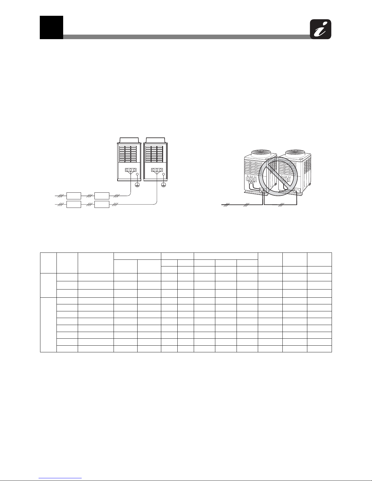
4-2. Outdoor unit power supply
4-2-1. Heat recovery
Outdoor unit data
208/230 V model
Unit
type
Capacity
type
Model name
MMY-
Power supply
Voltage Range
Compressor
Fan Motor MCA MOCP
Phase and
frequency
Rated
voltage
Min. Max.
Unit No.1 Unit No.2 Unit No.3
(V) (V) (kW) (kW) (kW) (kW) (A) (A)
Single
unit
72
MAP0724FT9U
3 ~ 60 Hz 208/230 V 187 253 2.3 × 2 – – 1.0 34 40
96
MAP0964FT9U
3 ~ 60 Hz 208/230 V 187 253 2.1
× 3 – – 1.0 50 60
120
MAP1204FT9U
3 ~ 60 Hz 208/230 V 187 253 2.7
× 3 – – 1.0 52 60
Combined model
144 AP1444FT9UL 3 ~ 60 Hz 208/230 V 187 253 2.3 × 2 2.3 × 2 – 1.0 × 2 34 + 34 40 + 40
168 AP1684FT9UL 3 ~ 60 Hz 208/230 V 187 253 2.1
× 3 2.3 × 2 – 1.0 × 2 50 + 34 60 + 40
192 AP1924FT9UL 3 ~ 60 Hz 208/230 V 187 253 2.1
× 3 2.1 × 3 – 1.0 × 2 50 + 50 60 + 60
216 AP2164FT9UL 3 ~ 60 Hz 208/230 V 187 253 2.7
× 3 2.1 × 3 – 1.0 × 2 52 + 50 60 + 60
240 AP2404FT9UL 3 ~ 60 Hz 208/230 V 187 253 2.7
× 3 2.7 × 3 – 1.0 × 2 52 + 52 60 + 60
288 AP2884FT9UL 3 ~ 60 Hz 208/230 V 187 253 2.1
× 3 2.1 × 3 2.1 × 3 1.0 × 3
50 + 50 + 50 60 + 60 + 60
312 AP3124FT9UL 3 ~ 60 Hz 208/230 V 187 235 2.7 × 3 2.1 × 3 2.1 × 3 1.0 × 3
52 + 50 + 50 60 + 60 + 60
336 AP3364FT9UL 3 ~ 60 Hz 208/230 V 187 235 2.7 × 3 2.7 × 3 2.1 × 3 1.0 × 3
52 + 52 + 50 60 + 60 + 60
L1L2L3 L1L2L
3
Main power circuit
breaker
Disconnect per NEC
and local codes.
Power supply for
outdoor units
Incorrect
Every outdoor unit must have a dedicated power supply.
4 Wiring Design

4
Wiring Design
30
460 V model
Notes MCA: Minimum Circuit Amps (minimum circuit Amps requires for power supply design.)
MOCP: Maximum Overcurrent Protection (Amps)
Unit
type
Capacity
type
Model name
MMY-
Power supply
Voltage
Compressor
Fan Motor MCA MOCP
Phase
and
frequenc
Rated
voltage
Min. Max.
Unit Unit
Unit No.3
(V) (V) (kW) (kW) (kW) (kW) (A) (A)
Single
unit
72
MAP0724FT6U
3 ~ 60 Hz 460 V 414 506 2.3 × 2 – – 1.0 19 25
96
MAP0964FT6U
3 ~ 60 Hz 460 V 414 506 2.1 × 3 – – 1.0 28 35
120
MAP1204FT6U
3 ~ 60 Hz 460 V 414 506 2.7 × 3 – – 1.0 30 35
Combined model
144 AP1444FT6UL 3 ~ 60 Hz 460 V 414 506 2.3 × 2 2.3 × 2 – 1.0 × 2 19 + 19 25 + 25
168 AP1684FT6UL 3 ~ 60 Hz 460 V 414 506 2.1 × 3 2.3 × 2 – 1.0 × 2 28 + 19 35 + 25
192 AP1924FT6UL 3 ~ 60 Hz 460 V 414 506 2.1 × 3 2.1 × 3 – 1.0 × 2 28 + 28 35 + 35
216 AP2164FT6UL 3 ~ 60 Hz 460 V 414 506 2.7 × 3 2.1 × 3 – 1.0 × 2 30 + 28 35 + 35
240 AP2404FT6UL 3 ~ 60 Hz 460 V 414 506 2.7 × 3 2.7 × 3 – 1.0 × 2 30 + 30 35 + 35
288 AP2884FT6UL 3 ~ 60 Hz 460 V 414 506 2.1 × 3 2.1 × 3 2.1 × 3 1.0 × 3
28 + 28 + 28 35 + 35 + 35
312 AP3124FT6UL 3 ~ 60 Hz 460 V 414 506 2.7 × 3 2.1 × 3 2.1 × 3 1.0 × 3
30 + 28 + 28 35 + 35 + 35
336 AP3364FT6UL 3 ~ 60 Hz 460 V 414 506 2.7 × 3 2.7 × 3 2.1 × 3 1.0 × 3
30 + 30 + 30 35 + 35 + 35

4
Wiring Design
31
4-2-2. Heat pump
Outdoor unit data
208/230 V model
460 V model
Notes MCA: Minimum Circuit Amps (minimum circuit Amps requires for power supply design.)
MOCP: Maximum Overcurrent Protection (Amps)
Unit type
Capacity
type
Model name
MMY-
Power supply Voltage Range Compressor
Fan
Motor
MCA MOCP
Phase and
frequency
Nominal
Vol tag e
Min. Max. Unit No.1 Unit No.2
(V) (V) (kW) (kW) (kW) (A) (A)
Single
unit
072 MAP0724HT9UL 3 ~ 60 Hz 208/230 V 187 253 2.3 × 2 – 1.0 36 40
096 MAP0964HT9UL 3 ~ 60 Hz 208/230 V 187 253 2.1 × 3 – 1.0 50 60
114 MAP1144HT9UL 3 ~ 60 Hz 208/230 V 187 253 2.5 × 3 – 1.0 52 60
Combined
model
144 AP1444HT9UL 3 ~ 60 Hz 208/230 V 187 253 2.3 × 2 2.3 × 2 1.0 × 2 36 + 36 40 + 40
168 AP1684HT9UL 3 ~ 60 Hz 208/230 V 187 253 2.1 × 3 2.3 × 2 1.0 × 2 50 + 36 60 + 40
192 AP1924HT9UL 3 ~ 60 Hz 208/230 V 187 253 2.1 × 3 2.1 × 3 1.0 × 2 50 + 50 60 + 60
228 AP2284HT9UL 3 ~ 60 Hz 208/230 V 187 253 2.5 × 3 2.5 × 3 1.0 × 2 52 + 52 60 + 60
Unit type
Capacity
type
Model name
MMY-
Power supply Voltage Range Compressor
Fan
Motor
MCA MOCP
Phase and
frequency
Nominal
Vol tag e
Min. Max. Unit No.1 Unit No.2
(V) (V) (kW) (kW) (kW) (A) (A)
Single
unit
072 MAP0724HT6UL 3 ~ 60 Hz 460 V 414 506 2.3 × 2 – 1.0 18 20
096 MAP0964HT6UL 3 ~ 60 Hz 460 V 414 506 2.1 × 3 – 1.0 23 25
114 MAP1144HT6UL 3 ~ 60 Hz 460 V 414 506 2.5 × 3 – 1.0 24 25
Combined
model
144 AP1444HT6UL 3 ~ 60 Hz 460 V 414 506 2.3 × 2 2.3 × 2 1.0 × 2 18 + 18 20 + 20
168 AP1684HT6UL 3 ~ 60 Hz 460 V 414 506 2.1 × 3 2.3 × 2 1.0 × 2 23 + 18 25 + 20
192 AP1924HT6UL 3 ~ 60 Hz 460 V 414 506 2.1 × 3 2.1 × 3 1.0 × 2 23 + 23 25 + 25
228 AP2284HT6UL 3 ~ 60 Hz 460 V 414 506 2.5 × 3 2.5 × 3 1.0 × 2 24 + 24 25 + 25

4
Wiring Design
32
4-3. Indoor unit power supply
Electrical characteristics
MCA: Minimum Circuit Amps FLA: Full Load Amps
MOCP: Maximum Overcurrent Protection (Amps)
Power supply wire
Recommended wire diameter and wire length for power supply wire.
Type Model Nominal Voltage (V-Ph-Hz)
Voltage Range (V) FLA MCA MOCP
Min Max AAA
4-Way Cassette
type
MMU-AP0072H2UL 208/230-1-60 187 253 0.6 0.8 15
MMU-AP0092H2UL 208/230-1-60 187 253 0.6 0.8 15
MMU-AP0122H2UL 208/230-1-60 187 253 0.6 0.8 15
MMU-AP0182H2UL 208/230-1-60 187 253 0.6 0.8 15
MMU-AP0212H2UL 208/230-1-60 187 253 0.8 1.0 15
MMU-AP0242H2UL 208/230-1-60 187 253 0.8 1.0 15
MMU-AP0302H2UL 208/230-1-60 187 253 0.8 1.0 15
MMU-AP0362H2UL 208/230-1-60 187 253 1.0 1.3 15
MMU-AP0422H2UL 208/230-1-60 187 253 1.0 1.3 15
Compact 4-Way
Cassette type
MMU-AP0071MH2UL 208/230-1-60 187 253 0.4 0.5 15
MMU-AP0091MH2UL 208/230-1-60 187 253 0.4 0.5 15
MMU-AP0121MH2UL 208/230-1-60 187 253 0.4 0.5 15
MMU-AP0151MH2UL 208/230-1-60 187 253 0.5 0.7 15
MMU-AP0181MH2UL 208/230-1-60 187 253 0.5 0.7 15
Ceiling type
MMC-AP0181H2UL 208/230-1-60 187 253 0.4 0.5 15
MMC-AP0241H2UL 208/230-1-60 187 253 0.5 0.7 15
MMC-AP0361H2UL 208/230-1-60 187 253 0.8 1.0 15
MMC-AP0421H2UL 208/230-1-60 187 253 0.9 1.2 15
High Wall type
MMK-AP0073H2UL 208/230-1-60 187 253 0.2 0.3 15
MMK-AP0093H2UL 208/230-1-60 187 253 0.2 0.3 15
MMK-AP0123H2UL 208/230-1-60 187 253 0.2 0.3 15
MMK-AP0153H2UL 208/230-1-60 187 253 0.4 0.5 15
MMK-AP0183H2UL 208/230-1-60 187 253 0.4 0.5 15
MMK-AP0243H2UL 208/230-1-60 187 253 0.4 0.5 15
Medium Static
Ducted type
MMD-AP0074BH2UL 208/230-1-60 187 253 0.8 1.0 15
MMD-AP0094BH2UL 208/230-1-60 187 253 0.8 1.0 15
MMD-AP0124BH2UL 208/230-1-60 187 253 0.8 1.0 15
MMD-AP0154BH2UL 208/230-1-60 187 253 0.9 1.2 15
MMD-AP0184BH2UL 208/230-1-60 187 253 0.9 1.2 15
MMD-AP0214BH2UL 208/230-1-60 187 253 1.4 1.8 15
MMD-AP0244BH2UL 208/230-1-60 187 253 1.4 1.8 15
MMD-AP0304BH2UL 208/230-1-60 187 253 1.4 1.8 15
MMD-AP0364BH2UL 208/230-1-60 187 253 1.8 2.3 15
MMD-AP0424BH2UL 208/230-1-60 187 253 2.2 2.8 15
MMD-AP0484BH2UL 208/230-1-60 187 253 2.2 2.8 15
High Static Ducted
type
MMD-AP0304H2UL 208/230-1-60 187 253 2.34 2.93 15
MMD-AP0364H2UL 208/230-1-60 187 253 2.34 2.93 15
MMD-AP0484H2UL 208/230-1-60 187 253 2.92 3.65 15
MMD-AP0724H2UL 208/230-1-60 187 253 7.12 8.91 15
MMD-AP0964H2UL 208/230-1-60 187 253 8.34 10.43 15
Slim Ducted type
MMD-AP0074SPH2UL 208/230-1-60 187 253 0.58 0.73 15
MMD-AP0094SPH2UL 208/230-1-60 187 253 0.58 0.73 15
MMD-AP0124SPH2UL 208/230-1-60 187 253 0.60 0.75 15
MMD-AP0154SPH2UL 208/230-1-60 187 253 0.70 0.88 15
MMD-AP0184SPH2UL 208/230-1-60 187 253 0.80 1.00 15
Power supply wiring
Wire side : 2 × AWG12
Ground: 1 × AWG12 or thicker
Up to 164'1'' (50 m)
FS unit
Be sure to use the supplied cable. If the length between the indoor and FS unit exceeds 16 ft (5 m), connect by using
the connection cable kit (RBC-CBK15FUL). (Sold separately)

4
Wiring Design
33
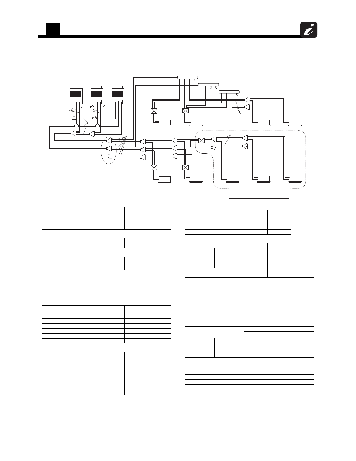
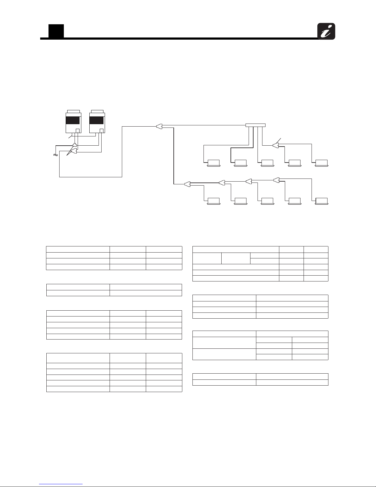
4-4. Design of control wiring
Summary of control wiring
1. All system interconnecting and central control wiring should be 2 conductor shielded cable.
2. On the header unit the control wire shield and the central control wire shield should both be connected to the
same ground screw in the header unit.
3. The remote control wiring can be 2 conductor un-shielded cable.
4. All system interconnecting and control wiring should be sized per table 1, 2 and 3.
5. Control wire and power line wire between FS unit and indoor unit are the accessory parts of FS unit. (Wire length
: 20 ft (6 m))
If the length between indoor unit and FS unit exceeds 16 ft (5 m), connect by using the connection cable kit sold
separately (RBC-CBK15FUL).
roodtuo rewolloFroodtuo redaeH
Central control
U1 U2 U3 U
4
U3U2U1U6U5U
4
U5 U6
U1 U2
U3 U
4
Control wiring between outdoor units (Shielded wire)
Central control wiring (Shielded wire)
Control wiring between indoor and outdoor units (Shielded wire)
Control wiring between indoor units (Shielded wire)
tinu SFtinu SF
2U1UBA2U1U
A
2U1UBA2U1UB
A
B
tinu roodnItinu roodnItinu roodnIIndoor unit
AB
A
BAB
lortnoc etomeRlortnoc etomeRlortnoc etomeR
(Group control)
CN81
CN02
CN81
CN02
CN81
(Cooling only)
4
Wiring Design
34
Restriction of control wiring
Be sure to keep the rule of below tables about size and length of control wiring.
Table-1 Control wiring between indoor and outdoor units (L1, L2, L3), Central control wiring (L4)
(*1): Total length of control wiring length for all refrigerant circuits (L1 + L2 + L3 + L4)
Table-2 Control wiring between outdoor units (L5)
Table-3 Remote control wiring (L6, L7)
Wiring 2-core
Type Shielded cable
Size/Length AWG16: Up to 3280 ft (1000 m) AWG14: Up to 6560 ft (2000 m) (*1)
Wiring 2-core
Type Shielded wire
Size/Length AWG16 to AWG14/Up to 330 ft (100 m) (L5)
Wire 2-core
Size AWG20 to AWG14
Length
• Up to 1640 ft (500 m) (L6 + L7)
• Up 1310 ft (400 m) in case of wireless remote control in group control.
• Up to 660 ft (200 m) total length of control wiring between indoor units (L6)
U3
U4
U1
U2
U1
U3
U2
U4
U5
U6
U1
U2
A B
U3
U4
U1
U2
U5
U6
U1
U2
A B
U1
U2
A
B
U1
U2
A
B
U1
U2
A
B
U3 U4
U1
U2
U5
U6
U3
U4
U1
U2
U5
U6
U1
U2
A
B
U1 U2
A B
U1 U2
A
B
U3
U4
U1
U2
U5
U6
L1
L5
L6
L7
L4
3L2L
Header
unit
Header
unit
Follower
unit
Header
unit
Follower
unit
Central
control
Outdoor unit
Indoor unit
Table-1
Table-2
Table-1
Remote control
Remote control
Remote control
Table-3

5
Outdoor unit
35
5 Outdoor unit
5-1. Specifications
(*1) Rated conditions
Cooling: Indoor air temperature 80 °F DryBulb/67 °F WetBulb, Outdoor air temperature 95 °F DryBulb
Heating: Indoor air temperature 70 °F DryBulb, Outdoor air temperature 47 °F DryBulb/43 °F WetBulb
072, 096 type: Equivalent piping length: 50 ft, Height difference: 0 ft, 120 type: Equivalent piping length: 75 ft, Height difference: 0 ft
(*2) Value for only outdoor unit
(*3) Setting is necessary
(*4) The amount does not consider extra piping length. Refrigerant must be added on site in accordance with the actual piping length.
(*5) High-pressure switch / High-pressure sensor / Low-pressure sensor / Fusible plug / PC board fuse / Inverter overload protector
(*6) Select wire size based on the larger value of MCA.
MCA: Minimum Circuit Amps (minimum circuit Amps required for power supply design.)
(*7) MOCP: Maximum Overcurrent Protection (Amps)
(*8) This specification is value as of June, 2013, please note that specification is subject to change without notice.
5-1-1. Heat recovery
5-1-1-1. 208/230 V model
Single unit (System with Non-ducted indoor units)
Outdoor unit model name MMY- MAP0724FT9UL MAP0964FT9UL MAP1204FT9UL
Power Supply
Nominal voltage V/Ph/Hz (208 / 230) / 3 / 60
Voltage range V 187 Minimum / 253 Maximum
Cooling
Nominal capacity (*1)
kBtu/h
72 96 120
Rated capacity 69 92 114
Rated power consumption (*2) kW 5.72 7.75 10.10
Rated EER Btu/W 12.1 11.9 11.3
Heating
Nominal capacity (*1)
kBtu/h
81 108 135
Rated capacity 77 103 120
Rated power consumption (*2) kW 6.43 8.74 10.23
Rated COP W/W 3.51 3.45 3.44
Starting Current A Soft Start
Dimension
Packing
Height In 76.3 76.3 76.3
Width In 41.8 50.5 50.5
Depth In 32.6 32.6 32.6
Unit
Height In 72.9 72.9 72.9
Width In 39.0 47.6 47.6
Depth In 30.7 30.7 30.7
Total Weight
Packed lbs 616 788 788
Unit lbs 583 751 751
Color Silky shade (Munsell 1Y8.5/0.5)
Compressor
Type Hermetic twin rotary compressor
Motor output kW 2.3 × 2 2.1 × 3 2.7 × 3
Fan unit
Fan Propeller fan
Motor output kW 1.0 1.0 1.0
Air volume cfm 5,120 7,060 7,620
Maximum external static pressure (*3) In WG 0.20 0.16 0.16
Heat exchanger Finned tube
Refrigerant
Name R410A
Charged refrigerant amount (*4) lbs 25.4 25.4 25.4
High-pressure switch psi OFF: 420 ON: 540
Protective devices (*5)
Electrical
specifications
Unit
MCA (*6) A 34 50 52
MOCP (*7) A 40 60 60
Refrigerant
piping
Liquid
Type Flare connection
Diameter In 1/2" 1/2" 1/2"
Suction
gas
Type Brazing connection
Diameter In 7/8" 7/8" 1-1/8"
Discharge
gas
Type Brazing connection
Diameter In 3/4" 3/4" 3/4"
Balance
Type Flare connection
Diameter In 3/8" 3/8" 3/8"
Indoor units
Maximum capacity of combined indoor units 80 to 125%
Maximum number of indoor units 12 16 20
Operation temperature range
Cooling FDB 14 to 109
Heating FWB -4 to 60
Sound pressure level
Cooling dB(A) 56.0 62.0 63.5
Heating dB(A) 58.0 63.0 65.5

5
Outdoor unit
36
Combination unit (System with Non-ducted indoor units)
(*1) Rated conditions
Cooling: Indoor air temperature 80 °F DryBulb/67 °F WetBulb, Outdoor air temperature 95 °F DryBulb
Heating: Indoor air temperature 70 °F DryBulb, Outdoor air temperature 47 °F DryBulb/43 °F WetBulb
Equivalent piping length: 100 ft, Height difference: 0 ft
(*2) Value for only outdoor unit
(*3) Setting is necessary
(*4) The amount does not consider extra piping length. Refrigerant must be added on site in accordance with the actual piping length.
(*5) High-pressure switch / High-pressure sensor / Low-pressure sensor / Fusible plug / PC board fuse / Inverter overload protector
(*6) Select wire size based on the larger value of MCA.
MCA: Minimum Circuit Amps (minimum circuit Amps required for power supply design.)
(*7) MOCP: Maximum Overcurrent Protection (Amps)
(*8) This specification is value as of June, 2013, please note that specification is subject to change without notice.
Outdoor unit set model name MMY- AP1444FT9UL AP1684FT9UL AP1924FT9UL AP2164FT9UL AP2404FT9UL
Outdoor unit model name MMY-
MAP0724FT9UL
MAP0724FT9UL
MAP0964FT9UL
MAP0724FT9UL
MAP0964FT9UL
MAP0964FT9UL
MAP1204FT9UL
MAP0964FT9UL
MAP1204FT9UL
MAP1204FT9UL
Power Supply
Nominal voltage V/Ph/Hz (208 / 230) / 3 / 60
Voltage range V 187 Minimum / 253 Maximum
Cooling
Nominal capacity (*1)
kBtu/h
144 168 192 216 240
Rated capacity 138 160 184 206 240
Rated power consumption (*2) kW 12.01 13.43 15.85 18.28 24.57
Rated EER Btu/W 11.5 11.9 11.6 11.3 9.8
Heating
Nominal capacity (*1)
kBtu/h
162 189 216 243 270
Rated capacity 154 180 206 224 226
Rated power consumption (*2) kW 12.94 15.90 18.30 20.12 19.54
Rated COP W/W 3.49 3.32 3.30 3.26 3.39
Starting Current A Soft Start
Total Weight
Packed lbs 616 + 616 788 + 616 788 + 788 788 + 788 788 + 788
Unit lbs 583 + 583 751 + 583 751 + 751 751 + 751 751 + 751
Color Silky shade (Munsell 1Y8.5/0.5)
Compressor
Type Hermetic twin rotary compressor
Motor output kW 2.3 × 2 + 2.3 × 2 2.1 × 3 + 2.3 × 2 2.1 × 3 + 2.1 × 3 2.7 × 3 + 2.1 × 3 2.7 × 3 + 2.7 × 3
Fan unit
Fan Propeller fan
Motor output kW 1.0 + 1.0 1.0 + 1.0 1.0 + 1.0 1.0 + 1.0 1.0 + 1.0
Air volume cfm 5,120 + 5,120 7,060 + 5,120 7,060 + 7,060 7,620 + 7,060 7,620 + 7,620
Maximum external static pressure (*3) In WG 0.20 0.16 0.16 0.16 0.16
Heat exchanger Finned tube
Refrigerant
Name R410A
Charged refrigerant amount (*4) lbs 25.4 + 25.4 25.4 + 25.4 25.4 + 25.4 25.4 + 25.4 25.4 + 25.4
High-pressure switch psi OFF: 420 ON: 540
Protective devices (*5)
Electrical
specifications
Unit
MCA (*6) A 34 + 34 50 + 34 50 + 50 52 + 50 52 + 52
MOCP (*7) A 40 + 40 60 + 40 60 + 60 60 + 60 60 + 60
Refrigerant
piping
Liquid
Type Flare connection
Diameter In 5/8" 3/4" 3/4" 3/4" 3/4"
Suction
gas
Type Brazing connection
Diameter In 1-1/8" 1-1/8" 1-1/8" 1-3/8" 1-3/8"
Discharge
gas
Type Brazing connection
Diameter In 7/8" 7/8" 7/8" 1-1/8" 1-1/8"
Balance
Type Flare connection
Diameter In 3/8" 3/8" 3/8" 3/8" 3/8"
Indoor units
Maximum capacity of combined indoor units 80 to 125%
Maximum number of indoor units 24 28 32 36 40
Operation temperature range
Cooling FDB 14 to 109
Heating FWB -4 to 60
Sound pressure level
Cooling dB(A) 59.0 63.0 65.5 66.0 66.5
Heating dB(A) 61.0 64.5 66.0 67.5 68.5

5
Outdoor unit
37
Combination unit (System with Non-ducted indoor units)
(*1) Rated conditions
Cooling: Indoor air temperature 80 °F DryBulb/67 °F WetBulb, Outdoor air temperature 95 °F DryBulb
Heating: Indoor air temperature 70 °F DryBulb, Outdoor air temperature 47 °F DryBulb/43 °F WetBulb
Equivalent piping length: 100 ft, Height difference: 0 ft
(*2) Value for only outdoor unit
(*3) Setting is necessary
(*4) The amount does not consider extra piping length. Refrigerant must be added on site in accordance with the actual piping length.
(*5) High-pressure switch / High-pressure sensor / Low-pressure sensor / Fusible plug / PC board fuse / Inverter overload protector
(*6) Select wire size based on the larger value of MCA.
MCA: Minimum Circuit Amps (minimum circuit Amps required for power supply design.)
(*7) MOCP: Maximum Overcurrent Protection (Amps)
(*8) This specification is value as of June, 2013, please note that specification is subject to change without notice.
Outdoor unit set model name MMY- AP2884FT9UL AP3124FT9UL AP3364FT9UL
Outdoor unit model name MMY-
MAP0964FT9UL
MAP0964FT9UL
MAP0964FT9UL
MAP1204FT9UL
MAP0964FT9UL
MAP0964FT9UL
MAP1204FT9UL
MAP1204FT9UL
MAP0964FT9UL
Power Supply
Nominal voltage V/Ph/Hz (208 / 230) / 3 / 60
Voltage range V 187 Minimum / 253 Maximum
Cooling
Nominal capacity (*1)
kBtu/h
288 312 336
Rated capacity 276 302 328
Rated power consumption (*2) kW 25.23 29.53 33.02
Rated EER Btu/W 10.9 10.2 9.9
Heating
Nominal capacity (*1)
kBtu/h
324 350 378
Rated capacity 288 302 316
Rated power consumption (*2) kW 25.82 26.98 28.14
Rated COP W/W 3.27 3.28 3.29
Starting Current A Soft Start
Total Weight
Packed lbs 788 + 788 + 788 788 + 788 + 788 788 + 788 + 788
Unit lbs 751 + 751 + 751 751 + 751 + 751 751 + 751 + 751
Color Silky shade (Munsell 1Y8.5/0.5)
Compressor
Type Hermetic twin rotary compressor
Motor output kW 2.1 × 3 + 2.1 × 3 + 2.1 × 3 2.7 × 3 + 2.1 × 3 + 2.1 × 3 2.7 × 3 + 2.7 × 3 + 2.1 × 3
Fan unit
Fan Propeller fan
Motor output kW 1.0 + 1.0 + 1.0 1.0 + 1.0 + 1.0 1.0 + 1.0 + 1.0
Air volume cfm 7060 + 7060 + 7060 7620 + 7060 + 7060 7620 + 7620 + 7060
Maximum external static pressure (*3) In WG 0.16 0.16 0.16
Heat exchanger Finned tube
Refrigerant
Name R410A
Charged refrigerant amount (*4) lbs 25.4 + 25.4 + 25.4 25.4 + 25.4 + 25.4 25.4 + 25.4 + 25.4
High-pressure switch psi OFF: 420 ON: 540
Protective devices (*5)
Electrical
specifications
Unit
MCA (*6) A 50 + 50 + 50 50 + 50 + 50 52 + 52 + 50
MOCP (*7) A 60 + 60 + 60 60 + 60 + 60 60 + 60 + 60
Refrigerant
piping
Liquid
Type Flare connection
Diameter In 7/8" 7/8" 7/8"
Suction
gas
Type Brazing connection
Diameter In 1-3/8" 1-3/8" 1-3/8"
Discharge
gas
Type Brazing connection
Diameter In 1-1/8" 1-1/8" 1-1/8"
Balance
Type Flare connection
Diameter In 3/8" 3/8" 3/8"
Indoor units
Maximum capacity of combined indoor units 80 to 125%
Maximum number of indoor units 48 48 48
Operation temperature range
Cooling FDB 14 to 109
Heating FWB -4 to 60
Sound pressure level
Cooling dB(A) 67.0 67.5 68.0
Heating dB(A) 68.0 69.0 70.0

5
Outdoor unit
38
Single unit (System with ducted indoor units)
(*1) Rated conditions
Cooling: Indoor air temperature 80 °F DryBulb/67 °F WetBulb, Outdoor air temperature 95 °F DryBulb
Heating: Indoor air temperature 70 °F DryBulb, Outdoor air temperature 47 °F DryBulb/43 °F WetBulb
Equivalent piping length: 25 ft, Height difference: 0 ft
(*2) Value for only outdoor unit
(*3) Setting is necessary
(*4) The amount does not consider extra piping length. Refrigerant must be added on site in accordance with the actual piping length.
(*5) High-pressure switch / High-pressure sensor / Low-pressure sensor / Fusible plug / PC board fuse / Inverter overload protector
(*6) Select wire size based on the larger value of MCA.
MCA: Minimum Circuit Amps (minimum circuit Amps required for power supply design.)
(*7) MOCP: Maximum Overcurrent Protection (Amps)
(*8) This specification is value as of June, 2013, please note that specification is subject to change without notice.
Outdoor unit model name MMY- MAP0724FT9UL MAP0964FT9UL MAP1204FT9UL
Power Supply
Nominal voltage V/Ph/Hz (208 / 230) / 3 / 60
Voltage range V 187 Minimum / 253 Maximum
Cooling
Nominal capacity (*1)
kBtu/h
72 96 120
Rated capacity 70 92 118
Rated power consumption (*2) kW 5.64 7.79 10.04
Rated EER Btu/W 12.4 11.8 11.8
Heating
Nominal capacity (*1)
kBtu/h
81 108 135
Rated capacity 77 103 113
Rated power consumption (*2) kW 6.35 8.52 9.10
Rated COP W/W 3.55 3.54 3.64
Starting Current A Soft Start
Dimension
Packing
Height In 76.3 76.3 76.3
Width In 41.8 50.5 50.5
Depth In 32.6 32.6 32.6
Unit
Height In 72.9 72.9 72.9
Width In 39.0 47.6 47.6
Depth In 30.7 30.7 30.7
Total Weight
Packed lbs 616 788 788
Unit lbs 583 751 751
Color Silky shade (Munsell 1Y8.5/0.5)
Compressor
Type Hermetic twin rotary compressor
Motor output kW 2.3 × 2 2.1 × 3 2.7 × 3
Fan unit
Fan Propeller fan
Motor output kW 1.0 1.0 1.0
Air volume cfm 5,120 7,060 7,620
Maximum external static pressure (*3) In WG 0.20 0.16 0.16
Heat exchanger Finned tube
Refrigerant
Name R410A
Charged refrigerant amount (*4) lbs 25.4 25.4 25.4
High-pressure switch psi OFF: 420 ON: 540
Protective devices (*5)
Electrical
specifications
Unit
MCA (*6) A 34 50 52
MOCP (*7) A 40 60 60
Refrigerant
piping
Liquid
Type Flare connection
Diameter In 1/2" 1/2" 1/2"
Suction
gas
Type Brazing connection
Diameter In 7/8" 7/8" 1-1/8"
Discharge
gas
Type Brazing connection
Diameter In 3/4" 3/4" 3/4"
Balance
Type Flare connection
Diameter In 3/8" 3/8" 3/8"
Indoor units
Maximum capacity of combined indoor units 80 to 120%
Maximum number of indoor units 11 15 19
Operation temperature range
Cooling FDB 14 to 109
Heating FWB -4 to 60
Sound pressure level
Cooling dB(A) 56.0 62.0 63.5
Heating dB(A) 58.0 63.0 65.5

5
Outdoor unit
39
Combination unit (System with ducted indoor units)
(*1) Rated conditions
Cooling: Indoor air temperature 80 °F DryBulb/67 °F WetBulb, Outdoor air temperature 95 °F DryBulb
Heating: Indoor air temperature 70 °F DryBulb, Outdoor air temperature 47 °F DryBulb/43 °F WetBulb
Equivalent piping length: 50 ft, Height difference: 0 ft
(*2) Value for only outdoor unit
(*3) Setting is necessary
(*4) The amount does not consider extra piping length. Refrigerant must be added on site in accordance with the actual piping length.
(*5) High-pressure switch / High-pressure sensor / Low-pressure sensor / Fusible plug / PC board fuse / Inverter overload protector
(*6) Select wire size based on the larger value of MCA.
MCA: Minimum Circuit Amps (minimum circuit Amps required for power supply design.)
(*7) MOCP: Maximum Overcurrent Protection (Amps)
(*8) This specification is value as of June, 2013, please note that specification is subject to change without notice.
Outdoor unit set model name MMY- AP1444FT9UL AP1684FT9UL AP1924FT9UL AP2164FT9UL AP2404FT9UL
Outdoor unit model name MMY-
MAP0724FT9UL
MAP0724FT9UL
MAP0964FT9UL
MAP0724FT9UL
MAP0964FT9UL
MAP0964FT9UL
MAP1204FT9UL
MAP0964FT9UL
MAP1204FT9UL
MAP1204FT9UL
Power Supply
Nominal voltage V/Ph/Hz (208 / 230) / 3 / 60
Voltage range V 187 Minimum / 253 Maximum
Cooling
Nominal capacity (*1)
kBtu/h
144 168 192 216 240
Rated capacity 138 160 184 206 240
Rated power consumption (*2) kW 11.96 13.47 15.47 18.79 21.34
Rated EER Btu/W 11.5 11.9 11.9 11.0 11.2
Heating
Nominal capacity (*1)
kBtu/h
162 189 216 243 270
Rated capacity 152 180 200 206 226
Rated power consumption (*2) kW 13.20 15.47 17.06 17.78 19.61
Rated COP W/W 3.37 3.41 3.44 3.40 3.38
Starting Current A Soft Start
Total Weight
Packed lbs 616 + 616 788 + 616 788 + 788 788 + 788 788 + 788
Unit lbs 583 + 583 751 + 583 751 + 751 751 + 751 751 + 751
Color Silky shade (Munsell 1Y8.5/0.5)
Compressor
Type Hermetic twin rotary compressor
Motor output kW 2.3 × 2 + 2.3 × 2 2.1 × 3 + 2.3 × 2 2.1 × 3 + 2.1 × 3 2.7 × 3 + 2.1× 3 2.7 × 3 + 2.7 × 3
Fan unit
Fan Propeller fan
Motor output kW 1.0 + 1.0 1.0 + 1.0 1.0 + 1.0 1.0 + 1.0 1.0 + 1.0
Air volume cfm 5,120 + 5,120 7,060 + 5,120 7,060 + 7,060 7,620 + 7,060 7,620 + 7,620
Maximum external static pressure (*3) In WG 0.20 0.16 0.16 0.16 0.16
Heat exchanger Finned tube
Refrigerant
Name R410A
Charged refrigerant amount (*4) lbs 25.4 + 25.4 25.4 + 25.4 25.4 + 25.4 25.4 + 25.4 25.4 + 25.4
High-pressure switch psi OFF: 420 ON: 540
Protective devices (*5)
Electrical
specifications
Unit
MCA (*6) A 34 + 34 50 + 34 50 + 50 52 + 50 52 + 52
MOCP (*7) A 40 + 40 60 + 40 60 + 60 60 + 60 60 + 60
Refrigerant
piping
Liquid
Type Flare connection
Diameter In 5/8" 3/4" 3/4" 3/4" 3/4"
Suction
gas
Type Brazing connection
Diameter In 1-1/8" 1-1/8" 1-1/8" 1-3/8" 1-3/8"
Discharge
gas
Type Brazing connection
Diameter In 7/8" 7/8" 7/8" 1-1/8" 1-1/8"
Balance
Type Flare connection
Diameter In 3/8" 3/8" 3/8" 3/8" 3/8"
Indoor units
Maximum capacity of combined indoor units 80 to 120%
Maximum number of indoor units 23 26 30 34 38
Operation temperature range
Cooling FDB 14 to 109
Heating FWB -4 to 60
Sound pressure level
Cooling dB(A) 59.0 63.0 65.5 66.0 66.5
Heating dB(A) 61.0 64.5 66.0 67.5 68.5

5
Outdoor unit
40
Combination unit (System with ducted indoor units)
(*1) Rated conditions
Cooling: Indoor air temperature 80 °F DryBulb/67 °F WetBulb, Outdoor air temperature 95 °F DryBulb
Heating: Indoor air temperature 70 °F DryBulb, Outdoor air temperature 47 °F DryBulb/43 °F WetBulb
Equivalent piping length: 100 ft, Height difference: 0 ft
(*2) Value for only outdoor unit
(*3) Setting is necessary
(*4) The amount does not consider extra piping length. Refrigerant must be added on site in accordance with the actual piping length.
(*5) High-pressure switch / High-pressure sensor / Low-pressure sensor / Fusible plug / PC board fuse / Inverter overload protector
(*6) Select wire size based on the larger value of MCA.
MCA: Minimum Circuit Amps (minimum circuit Amps required for power supply design.)
(*7) MOCP: Maximum Overcurrent Protection (Amps)
(*8) This specification is value as of June, 2013, please note that specification is subject to change without notice.
Outdoor unit set model name MMY- AP2884FT9UL AP3124FT9UL AP3364FT9UL
Outdoor unit model name MMY-
MAP0964FT9UL
MAP0964FT9UL
MAP0964FT9UL
MAP1204FT9UL
MAP0964FT9UL
MAP0964FT9UL
MAP1204FT9UL
MAP1204FT9UL
MAP0964FT9UL
Power Supply
Nominal voltage V/Ph/Hz (208 / 230) / 3 / 60
Voltage range V 187 Minimum / 253 Maximum
Cooling
Nominal capacity (*1)
kBtu/h
288 312 336
Rated capacity 276 302 328
Rated power consumption (*2) kW 23.74 27.61 31.98
Rated EER Btu/W 11.6 10.9 10.3
Heating
Nominal capacity (*1)
kBtu/h
324 350 378
Rated capacity 272 278 278
Rated power consumption (*2) kW 23.79 24.31 24.31
Rated COP W/W 3.35 3.35 3.35
Starting Current A Soft Start
Total Weight
Packed lbs 788 + 788 + 788 788 + 788 + 788 788 + 788 + 788
Unit lbs 751 + 751 + 751 751 + 751 + 751 751 + 751 + 751
Color Silky shade (Munsell 1Y8.5/0.5)
Compressor
Type Hermetic twin rotary compressor
Motor output kW 2.1 × 3 + 2.1 × 3 + 2.1 × 3 2.7 × 3 + 2.1 × 3 + 2.1 × 3 2.7 × 3 + 2.7 × 3 + 2.1 × 3
Fan unit
Fan Propeller fan
Motor output kW 1.0 + 1.0 + 1.0 1.0 + 1.0 + 1.0 1.0 + 1.0 + 1.0
Air volume cfm 7060 + 7060 + 7060 7620 + 7060 + 7060 7620 + 7620 + 7060
Maximum external static pressure (*3) In WG 0.16 0.16 0.16
Heat exchanger Finned tube
Refrigerant
Name R410A
Charged refrigerant amount (*4) lbs 25.4 + 25.4 + 25.4 25.4 + 25.4 + 25.4 25.4 + 25.4 + 25.4
High-pressure switch psi OFF: 420 ON: 540
Protective devices (*5)
Electrical
specifications
Unit
MCA (*6) A 50 + 50 + 50 52 + 50 + 50 52 + 52 + 50
MOCP (*7) A 60 + 60 + 60 60 + 60 + 60 60 + 60 + 60
Refrigerant
piping
Liquid
Type Flare connection
Diameter In 7/8" 7/8" 7/8"
Suction
gas
Type Brazing connection
Diameter In 1-3/8" 1-3/8" 1-3/8"
Discharge
gas
Type Brazing connection
Diameter In 1-1/8" 1-1/8" 1-1/8"
Balance
Type Flare connection
Diameter In 3/8" 3/8" 3/8"
Indoor units
Maximum capacity of combined indoor units 80 to 120%
Maximum number of indoor units 46 48 48
Operation temperature range
Cooling FDB 14 to 109
Heating FWB -4 to 60
Sound pressure level
Cooling dB(A) 67.0 67.5 68.0
Heating dB(A) 68.0 69.0 70.0

5
Outdoor unit
41
5-1-1-2. 460 V model
Single unit (System with Non-ducted indoor units)
(*1) Rated conditions
Cooling: Indoor air temperature 80 °F DryBulb/67 °F WetBulb, Outdoor air temperature 95 °F DryBulb
Heating: Indoor air temperature 70 °F DryBulb, Outdoor air temperature 47 °F DryBulb/43 °F WetBulb
072, 096 type: Equivalent piping length: 50 ft, Height difference: 0 ft, 120 type: Equivalent piping length: 75 ft, Height difference: 0 ft
(*2) Value for only outdoor unit
(*3) Setting is necessary
(*4) The amount does not consider extra piping length. Refrigerant must be added on site in accordance with the actual piping length.
(*5) High-pressure switch / High-pressure sensor / Low-pressure sensor / Fusible plug / PC board fuse / Inverter overload protector
(*6) Select wire size based on the larger value of MCA.
MCA: Minimum Circuit Amps (minimum circuit Amps required for power supply design.)
(*7) MOCP: Maximum Overcurrent Protection (Amps)
(*8) This specification is value as of June, 2013, please note that specification is subject to change without notice.
Outdoor unit model name MMY- MAP0724FT6UL MAP0964FT6UL MAP1204FT6UL
Power Supply
Nominal voltage V/Ph/Hz 460 / 3 / 60
Voltage range V 414 Minimum / 506 Maximum
Cooling
Nominal capacity (*1)
kBtu/h
72 96 120
Rated capacity 69 92 114
Rated power consumption (*2) kW 5.72 7.75 10.10
Rated EER Btu/W 12.1 11.9 11.3
Heating
Nominal capacity (*1)
kBtu/h
81 108 135
Rated capacity 77 103 120
Rated power consumption (*2) kW 6.43 8.74 10.23
Rated COP W/W 3.51 3.45 3.44
Starting Current A Soft Start
Dimension
Packing
Height In 76.3 76.3 76.3
Width In 41.8 50.5 50.5
Depth In 32.6 32.6 32.6
Unit
Height In 72.9 72.9 72.9
Width In 39.0 47.6 47.6
Depth In 30.7 30.7 30.7
Total Weight
Packed lbs 691 863 863
Unit lbs 658 826 826
Color Silky shade (Munsell 1Y8.5/0.5)
Compressor
Type Hermetic twin rotary compressor
Motor output kW 2.3 × 2 2.1 × 3 2.7 × 3
Fan unit
Fan Propeller fan
Motor output kW 1.0 1.0 1.0
Air volume cfm 5,120 7,060 7,620
Maximum external static pressure (*3) In WG 0.20 0.16 0.16
Heat exchanger Finned tube
Refrigerant
Name R410A
Charged refrigerant amount (*4) lbs 25.4 25.4 25.4
High-pressure switch psi OFF: 420 ON: 540
Protective devices (*5)
Electrical
specifications
Unit
MCA (*6) A 19 28 30
MOCP (*7) A 25 35 35
Refrigerant
piping
Liquid
Type Flare connection
Diameter In 1/2" 1/2" 1/2"
Suction
gas
Type Brazing connection
Diameter In 7/8" 7/8" 1-1/8"
Discharge
gas
Type Brazing connection
Diameter In 3/4" 3/4" 3/4"
Balance
Type Flare connection
Diameter In 3/8" 3/8" 3/8"
Indoor units
Maximum capacity of combined indoor units 80 to 125%
Maximum number of indoor units 12 16 20
Operation temperature range
Cooling FDB 14 to 109
Heating FWB -4 to 60
Sound pressure level
Cooling dB(A) 56.0 62.0 63.5
Heating dB(A) 58.0 63.0 65.5

5
Outdoor unit
42
Combination unit (System with Non-ducted indoor units)
(*1) Rated conditions
Cooling: Indoor air temperature 80 °F DryBulb/67 °F WetBulb, Outdoor air temperature 95 °F DryBulb
Heating: Indoor air temperature 70 °F DryBulb, Outdoor air temperature 47 °F DryBulb/43 °F WetBulb
Equivalent piping length: 100 ft, Height difference: 0 ft
(*2) Value for only outdoor unit
(*3) Setting is necessary
(*4) The amount does not consider extra piping length. Refrigerant must be added on site in accordance with the actual piping length.
(*5) High-pressure switch / High-pressure sensor / Low-pressure sensor / Fusible plug / PC board fuse / Inverter overload protector
(*6) Select wire size based on the larger value of MCA.
MCA: Minimum Circuit Amps (minimum circuit Amps required for power supply design.)
(*7) MOCP: Maximum Overcurrent Protection (Amps)
(*8) This specification is value as of June, 2013, please note that specification is subject to change without notice.
Outdoor unit set model name MMY- AP1444FT6UL AP1684FT6UL AP1924FT6UL AP2164FT6UL AP2404FT6UL
Outdoor unit model name MMY-
MAP0724FT6UL
MAP0724FT6UL
MAP0964FT6UL
MAP0724FT6UL
MAP0964FT6UL
MAP0964FT6UL
MAP1204FT6UL
MAP0964FT6UL
MAP1204FT6UL
MAP1204FT6UL
Power Supply
Nominal voltage V/Ph/Hz 460 / 3 / 60
Voltage range V 414 Minimum / 506 Maximum
Cooling
Nominal capacity (*1)
kBtu/h
144 168 192 216 240
Rated capacity 138 160 184 206 240
Rated power consumption (*2) kW 12.01 13.43 15.85 18.28 24.57
Rated EER Btu/W 11.5 11.9 11.6 11.3 9.8
Heating
Nominal capacity (*1)
kBtu/h
162 189 216 243 270
Rated capacity 154 180 206 224 226
Rated power consumption (*2) kW 12.94 15.90 18.30 20.12 19.54
Rated COP W/W 3.49 3.32 3.30 3.26 3.39
Starting Current A Soft Start
Total Weight
Packed lbs 691 + 691 863 + 691 863 + 863 863 + 863 863 + 863
Unit lbs 658 + 658 826 + 658 826 + 826 826 + 826 826 + 826
Color Silky shade (Munsell 1Y8.5/0.5)
Compressor
Type Hermetic twin rotary compressor
Motor output kW 2.3 × 2 + 2.3 × 2 2.1 × 3 + 2.3 × 2 2.1 × 3 + 2.1 × 3 2.7 × 3 + 2.1 × 3 2.7 × 3 + 2.7 × 3
Fan unit
Fan Propeller fan
Motor output kW 1.0 + 1.0 1.0 + 1.0 1.0 + 1.0 1.0 + 1.0 1.0 + 1.0
Air volume cfm 5,120 + 5,120 7,060 + 5,120 7,060 + 7,060 7,620 + 7,060 7,620 + 7,620
Maximum external static pressure (*3) In WG 0.20 0.16 0.16 0.16 0.16
Heat exchanger Finned tube
Refrigerant
Name R410A
Charged refrigerant amount (*4) lbs 25.4 + 25.4 25.4 + 25.4 25.4 + 25.4 25.4 + 25.4 25.4 + 25.4
High-pressure switch psi OFF: 420 ON: 540
Protective devices (*5)
Electrical
specifications
Unit
MCA (*6) A 19 + 19 28 + 19 28 + 28 30 + 28 30 + 30
MOCP (*7) A 25 + 25 35 + 25 35 + 35 35 + 35 35 + 35
Refrigerant
piping
Liquid
Type Flare connection
Diameter In 5/8" 3/4" 3/4" 3/4" 3/4"
Suction
gas
Type Brazing connection
Diameter In 1-1/8" 1-1/8" 1-1/8" 1-3/8" 1-3/8"
Discharge
gas
Type Brazing connection
Diameter In 7/8" 7/8" 7/8" 1-1/8" 1-1/8"
Balance
Type Flare connection
Diameter In 3/8" 3/8" 3/8" 3/8" 3/8"
Indoor units
Maximum capacity of combined indoor units 80 to 125%
Maximum number of indoor units 24 28 32 36 40
Operation temperature range
Cooling FDB 14 to 109
Heating FWB -4 to 60
Sound pressure level
Cooling dB(A) 59.0 63.0 65.5 66.0 66.5
Heating dB(A) 61.0 64.5 66.0 67.5 68.5

5
Outdoor unit
43
Combination unit (System with Non-ducted indoor units)
(*1) Rated conditions
Cooling: Indoor air temperature 80 °F DryBulb/67 °F WetBulb, Outdoor air temperature 95 °F DryBulb
Heating: Indoor air temperature 70 °F DryBulb, Outdoor air temperature 47 °F DryBulb/43 °F WetBulb
Equivalent piping length: 100 ft, Height difference: 0 ft
(*2) Value for only outdoor unit
(*3) Setting is necessary
(*4) The amount does not consider extra piping length. Refrigerant must be added on site in accordance with the actual piping length.
(*5) High-pressure switch / High-pressure sensor / Low-pressure sensor / Fusible plug / PC board fuse / Inverter overload protector
(*6) Select wire size based on the larger value of MCA.
MCA: Minimum Circuit Amps (minimum circuit Amps required for power supply design.)
(*7) MOCP: Maximum Overcurrent Protection (Amps)
(*8) This specification is value as of June, 2013, please note that specification is subject to change without notice.
Outdoor unit set model name MMY- AP2884FT6UL AP3124FT6UL AP3364FT6UL
Outdoor unit model name MMY-
MAP0964FT6UL
MAP0964FT6UL
MAP0964FT6UL
MAP1204FT6UL
MAP0964FT6UL
MAP0964FT6UL
MAP1204FT6UL
MAP1204FT6UL
MAP0964FT6UL
Power Supply
Nominal voltage V/Ph/Hz 460 / 3 / 60
Voltage range V 414 Minimum / 506 Maximum
Cooling
Nominal capacity (*1)
kBtu/h
288 312 336
Rated capacity 276 302 328
Rated power consumption (*2) kW 25.23 29.53 33.02
Rated EER Btu/W 10.9 10.2 9.9
Heating
Nominal capacity (*1)
kBtu/h
324 350 378
Rated capacity 288 302 316
Rated power consumption (*2) kW 25.82 26.98 28.14
Rated COP W/W 3.27 3.28 3.29
Starting Current A Soft Start
Total Weight
Packed lbs 863 + 863 + 863 863 + 863 + 863 863 + 863 + 863
Unit lbs 826 + 826 + 826 826 + 826 + 826 826 + 826 + 826
Color Silky shade (Munsell 1Y8.5/0.5)
Compressor
Type Hermetic twin rotary compressor
Motor output kW 2.1 × 3 + 2.1 × 3 + 2.1 × 3 2.7 × 3 + 2.1 × 3 + 2.1 × 3 2.7 × 3 + 2.7 × 3 + 2.1 × 3
Fan unit
Fan Propeller fan
Motor output kW 1.0 + 1.0 + 1.0 1.0 + 1.0 + 1.0 1.0 + 1.0 + 1.0
Air volume cfm 7060 + 7060 + 7060 7620 + 7060 + 7060 7620 + 7620 + 7060
Maximum external static pressure (*3) In WG 0.16 0.16 0.16
Heat exchanger Finned tube
Refrigerant
Name R410A
Charged refrigerant amount (*4) lbs 25.4 + 25.4 + 25.4 25.4 + 25.4 + 25.4 25.4 + 25.4 + 25.4
High-pressure switch psi OFF: 420 ON: 540
Protective devices (*5)
Electrical
specifications
Unit
MCA (*6) A 28 + 28 + 28 30 + 28 + 28 30 + 30 + 28
MOCP (*7) A 35 + 35 + 35 35 + 35 + 35 35 + 35 + 35
Refrigerant
piping
Liquid
Type Flare connection
Diameter In 7/8" 7/8" 7/8"
Suction
gas
Type Brazing connection
Diameter In 1-3/8" 1-3/8" 1-3/8"
Discharge
gas
Type Brazing connection
Diameter In 1-1/8" 1-1/8" 1-1/8"
Balance
Type Flare connection
Diameter In 3/8" 3/8" 3/8"
Indoor units
Maximum capacity of combined indoor units 80 to 125%
Maximum number of indoor units 48 48 48
Operation temperature range
Cooling FDB 14 to 109
Heating FWB -4 to 60
Sound pressure level
Cooling dB(A) 67.0 67.5 68.0
Heating dB(A) 68.0 69.0 70.0

5
Outdoor unit
44
Single unit (System with ducted indoor units)
(*1) Rated conditions
Cooling: Indoor air temperature 80 °F DryBulb/67 °F WetBulb, Outdoor air temperature 95 °F DryBulb
Heating: Indoor air temperature 70 °F DryBulb, Outdoor air temperature 47 °F DryBulb/43 °F WetBulb
Equivalent piping length: 25 ft, Height difference: 0 ft
(*2) Value for only outdoor unit
(*3) Setting is necessary
(*4) The amount does not consider extra piping length. Refrigerant must be added on site in accordance with the actual piping length.
(*5) High-pressure switch / High-pressure sensor / Low-pressure sensor / Fusible plug / PC board fuse / Inverter overload protector
(*6) Select wire size based on the larger value of MCA.
MCA: Minimum Circuit Amps (minimum circuit Amps required for power supply design.)
(*7) MOCP: Maximum Overcurrent Protection (Amps)
(*8) This specification is value as of June, 2013, please note that specification is subject to change without notice.
Outdoor unit model name MMY- MAP0724FT6UL MAP0964FT6UL MAP1204FT6UL
Power Supply
Nominal voltage V/Ph/Hz 460 / 3 / 60
Voltage range V 414 Minimum / 506 Maximum
Cooling
Nominal capacity (*1)
kBtu/h
72 96 120
Rated capacity 70 92 118
Rated power consumption (*2) kW 5.64 7.79 10.04
Rated EER Btu/W 12.4 11.8 11.8
Heating
Nominal capacity (*1)
kBtu/h
81 108 135
Rated capacity 77 103 113
Rated power consumption (*2) kW 6.35 8.52 9.10
Rated COP W/W 3.55 3.54 3.64
Starting Current A Soft Start
Dimension
Packing
Height In 76.3 76.3 76.3
Width In 41.8 50.5 50.5
Depth In 32.6 32.6 32.6
Unit
Height In 72.9 72.9 72.9
Width In 39.0 47.6 47.6
Depth In 30.7 30.7 30.7
Total Weight
Packed lbs 691 863 863
Unit lbs 658 826 826
Color Silky shade (Munsell 1Y8.5/0.5)
Compressor
Type Hermetic twin rotary compressor
Motor output kW 2.3 × 2 2.1 × 3 2.7 × 3
Fan unit
Fan Propeller fan
Motor output kW 1.0 1.0 1.0
Air volume cfm 5,120 7,060 7,620
Maximum external static pressure (*3) In WG 0.20 0.16 0.16
Heat exchanger Finned tube
Refrigerant
Name R410A
Charged refrigerant amount (*4) lbs 25.4 25.4 25.4
High-pressure switch psi OFF: 420 ON: 540
Protective devices (*5)
Electrical
specifications
Unit
MCA (*6) A 19 28 30
MOCP (*7) A 25 35 35
Refrigerant
piping
Liquid
Type Flare connection
Diameter In 1/2" 1/2" 1/2"
Suction
gas
Type Brazing connection
Diameter In 7/8" 7/8" 1-1/8"
Discharge
gas
Type Brazing connection
Diameter In 3/4" 3/4" 3/4"
Balance
Type Flare connection
Diameter In 3/8" 3/8" 3/8"
Indoor units
Maximum capacity of combined indoor units 80 to 120%
Maximum number of indoor units 11 15 19
Operation temperature range
Cooling FDB 14 to 109
Heating FWB -4 to 60
Sound pressure level
Cooling dB(A) 56.0 62.0 63.5
Heating dB(A) 58.0 63.0 65.5

5
Outdoor unit
45
Combination unit (System with ducted indoor units)
(*1) Rated conditions
Cooling: Indoor air temperature 80 °F DryBulb/67 °F WetBulb, Outdoor air temperature 95 °F DryBulb
Heating: Indoor air temperature 70 °F DryBulb, Outdoor air temperature 47 °F DryBulb/43 °F WetBulb
Equivalent piping length: 50 ft, Height difference: 0 ft
(*2) Value for only outdoor unit
(*3) Setting is necessary
(*4) The amount does not consider extra piping length. Refrigerant must be added on site in accordance with the actual piping length.
(*5) High-pressure switch / High-pressure sensor / Low-pressure sensor / Fusible plug / PC board fuse / Inverter overload protector
(*6) Select wire size based on the larger value of MCA.
MCA: Minimum Circuit Amps (minimum circuit Amps required for power supply design.)
(*7) MOCP: Maximum Overcurrent Protection (Amps)
(*8) This specification is value as of June, 2013, please note that specification is subject to change without notice.
Outdoor unit set model name MMY- AP1444FT6UL AP1684FT6UL AP1924FT6UL AP2164FT6UL AP2404FT6UL
Outdoor unit model name MMY-
MAP0724FT6UL
MAP0724FT6UL
MAP0964FT6UL
MAP0724FT6UL
MAP0964FT6UL
MAP0964FT6UL
MAP1204FT6UL
MAP0964FT6UL
MAP1204FT6UL
MAP1204FT6UL
Power Supply
Nominal voltage V/Ph/Hz 460 / 3 / 60
Voltage range V 414 Minimum / 506 Maximum
Cooling
Nominal capacity (*1)
kBtu/h
144 168 192 216 240
Rated capacity 138 160 184 206 240
Rated power consumption (*2) kW 11.96 13.47 15.47 18.79 21.34
Rated EER Btu/W 11.5 11.9 11.9 11.0 11.2
Heating
Nominal capacity (*1)
kBtu/h
162 189 216 243 270
Rated capacity 152 180 200 206 226
Rated power consumption (*2) kW 13.20 15.47 17.06 17.78 19.61
Rated COP W/W 3.37 3.41 3.44 3.40 3.38
Starting Current A Soft Start
Total Weight
Packed lbs 691 + 691 863 + 691 863 + 863 863 + 863 863 + 863
Unit lbs 658 + 658 826 + 658 826 + 826 826 + 826 826 + 826
Color Silky shade (Munsell 1Y8.5/0.5)
Compressor
Type Hermetic twin rotary compressor
Motor output kW 2.3 × 2 + 2.3 × 2 2.1 × 3 + 2.3 × 2 2.1 × 3 + 2.1 × 3 2.7 × 3 + 2.1 × 3 2.7 × 3 + 2.7 × 3
Fan unit
Fan Propeller fan
Motor output kW 1.0 + 1.0 1.0 + 1.0 1.0 + 1.0 1.0 + 1.0 1.0 + 1.0
Air volume cfm 5,120 + 5,120 7,060 + 5,120 7,060 + 7,060 7,620 + 7,060 7,620 + 7,620
Maximum external static pressure (*3) In WG 0.20 0.16 0.16 0.16 0.16
Heat exchanger Finned tube
Refrigerant
Name R410A
Charged refrigerant amount (*4) lbs 25.4 + 25.4 25.4 + 25.4 25.4 + 25.4 25.4 + 25.4 25.4 + 25.4
High-pressure switch psi OFF: 420 ON: 540
Protective devices (*5)
Electrical
specifications
Unit
MCA (*6) A 19 + 19 28 + 19 28 + 28 30 + 28 30 + 30
MOCP (*7) A 25 + 25 35 + 25 35 + 35 35 + 35 35 + 35
Refrigerant
piping
Liquid
Type Flare connection
Diameter In 5/8" 3/4" 3/4" 3/4" 3/4"
Suction
gas
Type Brazing connection
Diameter In 1-1/8" 1-1/8" 1-1/8" 1-3/8" 1-3/8"
Discharge
gas
Type Brazing connection
Diameter In 7/8" 7/8" 7/8" 1-1/8" 1-1/8"
Balance
Type Flare connection
Diameter In 3/8" 3/8" 3/8" 3/8" 3/8"
Indoor units
Maximum capacity of combined indoor units 80 to 120%
Maximum number of indoor units 23 26 30 34 38
Operation temperature range
Cooling FDB 14 to 109
Heating FWB -4 to 60
Sound pressure level
Cooling dB(A) 59.0 63.0 65.5 66.0 66.5
Heating dB(A) 61.0 64.5 66.0 67.5 68.5

5
Outdoor unit
46
Combination unit (System with ducted indoor units)
(*1) Rated conditions
Cooling: Indoor air temperature 80 °F DryBulb/67 °F WetBulb, Outdoor air temperature 95 °F DryBulb
Heating: Indoor air temperature 70 °F DryBulb, Outdoor air temperature 47 °F DryBulb/43 °F WetBulb
Equivalent piping length: 100 ft, Height difference: 0 ft
(*2) Value for only outdoor unit
(*3) Setting is necessary
(*4) The amount does not consider extra piping length. Refrigerant must be added on site in accordance with the actual piping length.
(*5) High-pressure switch / High-pressure sensor / Low-pressure sensor / Fusible plug / PC board fuse / Inverter overload protector
(*6) Select wire size based on the larger value of MCA.
MCA: Minimum Circuit Amps (minimum circuit Amps required for power supply design.)
(*7) MOCP: Maximum Overcurrent Protection (Amps)
(*8) This specification is value as of June, 2013, please note that specification is subject to change without notice.
Outdoor unit set model name MMY- AP2884FT6UL AP3124FT6UL AP3364FT6UL
Outdoor unit model name MMY-
MAP0964FT6UL
MAP0964FT6UL
MAP0964FT6UL
MAP1204FT6UL
MAP0964FT6UL
MAP0964FT6UL
MAP1204FT6UL
MAP1204FT6UL
MAP0964FT6UL
Power Supply
Nominal voltage V/Ph/Hz 460 / 3 / 60
Voltage range V 414 Minimum / 506 Maximum
Cooling
Nominal capacity (*1)
kBtu/h
288 312 336
Rated capacity 276 302 328
Rated power consumption (*2) kW 23.74 27.61 31.98
Rated EER Btu/W 11.6 10.9 10.3
Heating
Nominal capacity (*1)
kBtu/h
324 350 378
Rated capacity 272 278 278
Rated power consumption (*2) kW 23.79 24.31 24.31
Rated COP W/W 3.35 3.35 3.35
Starting Current A Soft Start
Total Weight
Packed lbs 863 + 863 + 863 863 + 863 + 863 863 + 863 + 863
Unit lbs 826 + 826 + 826 826 + 826 + 826 826 + 826 + 826
Color Silky shade (Munsell 1Y8.5/0.5)
Compressor
Type Hermetic twin rotary compressor
Motor output kW 2.1 × 3 + 2.1 × 3 + 2.1 × 3 2.7 × 3 + 2.1 × 3 + 2.1 × 3 2.7 × 3 + 2.7 × 3 + 2.1 × 3
Fan unit
Fan Propeller fan
Motor output kW 1.0 + 1.0 + 1.0 1.0 + 1.0 + 1.0 1.0 + 1.0 + 1.0
Air volume cfm 7060 + 7060 + 7060 7620 + 7060 + 7060 7620 + 7620 + 7060
Maximum external static pressure (*3) In WG 0.16 0.16 0.16
Heat exchanger Finned tube
Refrigerant
Name R410A
Charged refrigerant amount (*4) lbs 25.4 + 25.4 + 25.4 25.4 + 25.4 + 25.4 25.4 + 25.4 + 25.4
High-pressure switch psi OFF: 420 ON: 540
Protective devices (*5)
Electrical
specifications
Unit
MCA (*6) A 28 + 28 + 28 30 + 28 + 28 30 + 30 + 28
MOCP (*7) A 35 + 35 + 35 35 + 35 + 35 35 + 35 + 35
Refrigerant
piping
Liquid
Type Flare connection
Diameter In 7/8" 7/8" 7/8"
Suction
gas
Type Brazing connection
Diameter In 1-3/8" 1-3/8" 1-3/8"
Discharge
gas
Type Brazing connection
Diameter In 1-1/8" 1-1/8" 1-1/8"
Balance
Type Flare connection
Diameter In 3/8" 3/8" 3/8"
Indoor units
Maximum capacity of combined indoor units 80 to 120%
Maximum number of indoor units 46 48 48
Operation temperature range
Cooling FDB 14 to 109
Heating FWB -4 to 60
Sound pressure level
Cooling dB(A) 67.0 67.5 68.0
Heating dB(A) 68.0 69.0 70.0

5
Outdoor unit
47
(*1) Rated conditions
Cooling: Indoor air temperature 80 °F DryBulb/67 °F WetBulb, Outdoor air temperature 95 °F DryBulb
Heating: Indoor air temperature 70 °F DryBulb, Outdoor air temperature 47 °F DryBulb/43 °F WetBulb
072, 096 type: Equivalent piping length: 50 ft, Height difference: 0 ft, 114 type: Equivalent piping length: 75 ft, Height difference: 0 ft
(*2) Value for only outdoor unit
(*3) Setting is necessary
(*4) The amount does not consider extra piping length. Refrigerant must be added on site in accordance with the actual piping length.
(*5) High-pressure switch / High-pressure sensor / Low-pressure sensor / Fusible plug / PC board fuse / Inverter overload protector
(*6) Select wire size based on the larger value of MCA.
MCA: Minimum Circuit Amps (minimum circuit Amps required for power supply design.)
(*7) MOCP: Maximum Overcurrent Protection (Amps)
(*8) This specification is value as of June, 2013, please note that specification is subject to change without notice.
5-1-2. Heat pump
5-1-2-1. 208/230 V model
Single unit (System with Non-ducted indoor units)
Outdoor unit model name MMY- MAP0724HT9UL MAP0964HT9UL MAP1144HT9UL
Power Supply
Nominal voltage V/Ph/Hz (208 / 230) / 3 / 60
Voltage range V 187 Minimum / 253 Maximum
Cooling
Nominal capacity (*1)
kBtu/h
72 96 114
Rated capacity 69 92 114
Rated power consumption (*2) kW 6.10 8.11 10.16
Rated EER Btu/W 11.3 11.3 11.2
Heating
Nominal capacity (*1)
kBtu/h
81 108 128
Rated capacity 81 108 128
Rated power consumption (*2) kW 6.68 9.44 11.01
Rated COP W/W 3.55 3.35 3.41
Starting Current A Soft Start
Dimension
Packing
Height In 76.3 76.3 76.3
Width In 41.8 50.5 50.5
Depth In 32.6 32.6 32.6
Unit
Height In 72.9 72.9 72.9
Width In 39.0 47.6 47.6
Depth In 30.7 30.7 30.7
Total Weight
Packed lbs 579 779 779
Unit lbs 546 742 742
Color Silky shade (Munsell 1Y8.5/0.5)
Compressor
Type Hermetic twin rotary compressor
Motor output kW 2.3 × 2 2.1 × 3 2.5 × 3
Fan unit
Fan Propeller fan
Motor output kW 1.0 1.0 1.0
Air volume cfm 5,800 6,600 7,060
Maximum external static pressure (*3) In WG 0.20 0.20 0.20
Heat exchanger Finned tube
Refrigerant
Name R410A
Charged refrigerant amount (*4) lbs 25.4 25.4 25.4
High-pressure switch psi OFF: 420 ON: 540
Protective devices (*5)
Electrical
specifications
Unit
MCA (*6) A 36 50 52
MOCP (*7) A 40 60 60
Refrigerant
piping
Liquid
Type Flare connection
Diameter In 1/2" 1/2" 1/2"
Suction
gas
Type Brazing connection
Diameter In 7/8" 7/8" 1-1/8"
Balance
Type Flare connection
Diameter In 3/8" 3/8" 3/8"
Indoor units
Maximum capacity of combined indoor units 80 to 125%
Maximum number of indoor units 12 16 19
Operation temperature range
Cooling FDB 23 to 115
Heating FWB -4 to 60
Sound pressure level
Cooling dB(A) 56.0 60.0 62.0
Heating dB(A) 57.0 62.0 63.0

5
Outdoor unit
48
Combination unit (System with Non-ducted indoor units)
(*1) Rated conditions
Cooling: Indoor air temperature 80 °F DryBulb/67 °F WetBulb, Outdoor air temperature 95 °F DryBulb
Heating: Indoor air temperature 70 °F DryBulb, Outdoor air temperature 47 °F DryBulb/43 °F WetBulb
Equivalent piping length: 100 ft, Height difference: 0 ft
(*2) Value for only outdoor unit
(*3) Setting is necessary
(*4) The amount does not consider extra piping length. Refrigerant must be added on site in accordance with the actual piping length.
(*5) High-pressure switch / High-pressure sensor / Low-pressure sensor / Fusible plug / PC board fuse / Inverter overload protector
(*6) Select wire size based on the larger value of MCA.
MCA: Minimum Circuit Amps (minimum circuit Amps required for power supply design.)
(*7) MOCP: Maximum Overcurrent Protection (Amps)
(*8) This specification is value as of June, 2013, please note that specification is subject to change without notice.
Outdoor unit set model name MMY- AP1444HT9UL AP1684HT9UL AP1924HT9UL AP2284HT9UL
Outdoor unit model name MMY-
MAP0724HT9UL
MAP0724HT9UL
MAP0964HT9UL
MAP0724HT9UL
MAP0964HT9UL
MAP0964HT9UL
MAP1144HT9UL
MAP1144HT9UL
Power Supply
Nominal voltage V/Ph/Hz (208 / 230) / 3 / 60
Voltage range V 187 Minimum / 253 Maximum
Cooling
Nominal capacity (*1)
kBtu/h
144 168 192 228
Rated capacity 138 160 184 228
Rated power consumption (*2) kW 12.38 14.66 16.94 21.11
Rated EER Btu/W 11.1 10.9 10.9 10.8
Heating
Nominal capacity (*1)
kBtu/h
162 189 216 248
Rated capacity 162 188 212 248
Rated power consumption (*2) kW 13.75 16.95 19.12 21.32
Rated COP W/W 3.45 3.25 3.25 3.41
Starting Current A Soft Start
Total Weight
Packed lbs 579 + 579 779 + 579 779 + 779 779 + 779
Unit lbs 546 + 546 742 + 546 742 + 742 742 + 742
Color Silky shade (Munsell 1Y8.5/0.5)
Compressor
Type Hermetic twin rotary compressor
Motor output kW 2.3 × 2 + 2.3 × 2 2.1 × 3 + 2.3 × 2 2.1 × 3 + 2.1 × 3 2.5 × 3 + 2.5 × 3
Fan unit
Fan Propeller fan
Motor output kW 1.0 + 1.0 1.0 + 1.0 1.0 + 1.0 1.0 + 1.0
Air volume cfm 5,800 + 5,800 6,600 + 5,800 6,600 + 6,600 7,060 + 7,060
Maximum external static pressure (*3) In WG 0.20 0.20 0.20 0.20
Heat exchanger Finned tube
Refrigerant
Name R410A
Charged refrigerant amount (*4) lbs 25.4 + 25.4 25.4 + 25.4 25.4 + 25.4 25.4 + 25.4
High-pressure switch psi OFF: 420 ON: 540
Protective devices (*5)
Electrical
specifications
Unit
MCA (*6) A 36 + 36 50 + 36 50 + 50 52 + 52
MOCP (*7) A 40 + 40 60 + 40 60 + 60 60 + 60
Refrigerant
piping
Liquid
Type Flare connection
Diameter In 5/8" 5/8" 5/8" 3/4"
Suction
gas
Type Brazing connection
Diameter In 1-1/8" 1-1/8" 1-1/8" 1-3/8"
Balance
Type Flare connection
Diameter In 3/8" 3/8" 3/8" 3/8"
Indoor units
Maximum capacity of combined indoor units 80 to 125%
Maximum number of indoor units 24 28 32 38
Operation temperature range
Cooling FDB 23 to 115
Heating FWB -4 to 60
Sound pressure level
Cooling dB(A) 59.0 61.5 63.0 65.0
Heating dB(A) 60.0 63.5 65.0 66.0

5
Outdoor unit
49
Single unit (System with ducted indoor units)
(*1) Rated conditions
Cooling: Indoor air temperature 80 °F DryBulb/67 °F WetBulb, Outdoor air temperature 95 °F DryBulb
Heating: Indoor air temperature 70 °F DryBulb, Outdoor air temperature 47 °F DryBulb/43 °F WetBulb
Equivalent piping length: 25 ft, Height difference: 0 ft
(*2) Value for only outdoor unit
(*3) Setting is necessary
(*4) The amount does not consider extra piping length. Refrigerant must be added on site in accordance with the actual piping length.
(*5) High-pressure switch / High-pressure sensor / Low-pressure sensor / Fusible plug / PC board fuse / Inverter overload protector
(*6) Select wire size based on the larger value of MCA.
MCA: Minimum Circuit Amps (minimum circuit Amps required for power supply design.)
(*7) MOCP: Maximum Overcurrent Protection (Amps)
(*8) This specification is value as of June, 2013, please note that specification is subject to change without notice.
Outdoor unit model name MMY- MAP0724HT9UL MAP0964HT9UL MAP1144HT9UL
Power Supply
Nominal voltage V/Ph/Hz (208 / 230) / 3 / 60
Voltage range V 187 Minimum / 253 Maximum
Cooling
Nominal capacity (*1)
kBtu/h
72 96 114
Rated capacity 72 96 114
Rated power consumption (*2) kW 5.90 8.29 9.81
Rated EER Btu/W 12.2 11.6 11.6
Heating
Nominal capacity (*1)
kBtu/h
81 108 128
Rated capacity 81 104 126
Rated power consumption (*2) kW 6.50 8.87 10.47
Rated COP W/W 3.65 3.44 3.53
Starting Current A Soft Start
Dimension
Packing
Height In 76.3 76.3 76.3
Width In 41.8 50.5 50.5
Depth In 32.6 32.6 32.6
Unit
Height In 72.9 72.9 72.9
Width In 39.0 47.6 47.6
Depth In 30.7 30.7 30.7
Total Weight
Packed lbs 579 779 779
Unit lbs 546 742 742
Color Silky shade (Munsell 1Y8.5/0.5)
Compressor
Type Hermetic twin rotary compressor
Motor output kW 2.3 × 2 2.1 × 3 2.5 × 3
Fan unit
Fan Propeller fan
Motor output kW 1.0 1.0 1.0
Air volume cfm 5,800 6,600 7,060
Maximum external static pressure (*3) In WG 0.20 0.20 0.20
Heat exchanger Finned tube
Refrigerant
Name R410A
Charged refrigerant amount (*4) lbs 25.4 25.4 25.4
High-pressure switch psi OFF: 420 ON: 540
Protective devices (*5)
Electrical
specifications
Unit
MCA (*6) A 36 50 52
MOCP (*7) A 40 60 60
Refrigerant
piping
Liquid
Type Flare connection
Diameter In 1/2" 1/2" 1/2"
Suction
gas
Type Brazing connection
Diameter In 7/8" 7/8" 1-1/8"
Balance
Type Flare connection
Diameter In 3/8" 3/8" 3/8"
Indoor units
Maximum capacity of combined indoor units 80 to 120%
Maximum number of indoor units 11 15 18
Operation temperature range
Cooling FDB 23 to 115
Heating FWB -4 to 60
Sound pressure level
Cooling dB(A) 56.0 60.0 62.0
Heating dB(A) 57.0 62.0 63.0

5
Outdoor unit
50
Combination unit (System with ducted indoor units)
(*1) Rated conditions
Cooling: Indoor air temperature 80 °F DryBulb/67 °F WetBulb, Outdoor air temperature 95 °F DryBulb
Heating: Indoor air temperature 70 °F DryBulb, Outdoor air temperature 47 °F DryBulb/43 °F WetBulb
Equivalent piping length: 50 ft, Height difference: 0 ft
(*2) Value for only outdoor unit
(*3) Setting is necessary
(*4) The amount does not consider extra piping length. Refrigerant must be added on site in accordance with the actual piping length.
(*5) High-pressure switch / High-pressure sensor / Low-pressure sensor / Fusible plug / PC board fuse / Inverter overload protector
(*6) Select wire size based on the larger value of MCA.
MCA: Minimum Circuit Amps (minimum circuit Amps required for power supply design.)
(*7) MOCP: Maximum Overcurrent Protection (Amps)
(*8) This specification is value as of June, 2013, please note that specification is subject to change without notice.
Outdoor unit set model name MMY- AP1444HT9UL AP1684HT9UL AP1924HT9UL AP2284HT9UL
Outdoor unit model name MMY-
MAP0724HT9UL
MAP0724HT9UL
MAP0964HT9UL
MAP0724HT9UL
MAP0964HT9UL
MAP0964HT9UL
MAP1144HT9UL
MAP1144HT9UL
Power Supply
Nominal voltage V/Ph/Hz (208 / 230) / 3 / 60
Voltage range V 187 Minimum / 253 Maximum
Cooling
Nominal capacity (*1)
kBtu/h
144 168 192 228
Rated capacity 144 168 192 198
Rated power consumption (*2) kW 12.73 14.97 17.38 17.95
Rated EER Btu/W 11.3 11.3 11.0 11.0
Heating
Nominal capacity (*1)
kBtu/h
162 189 216 256
Rated capacity 162 184 200 214
Rated power consumption (*2) kW 13.92 16.12 17.58 18.87
Rated COP W/W 3.41 3.41 3.33 3.32
Starting Current A Soft Start
Total Weight
Packed lbs 579 + 579 779 + 579 779 + 779 779 + 779
Unit lbs 546 + 546 742 + 546 742 + 742 742 + 742
Color Silky shade (Munsell 1Y8.5/0.5)
Compressor
Type Hermetic twin rotary compressor
Motor output kW 2.3 × 2 + 2.3 × 2 2.1 × 3 + 2.3 × 2 2.1 × 3 + 2.1 × 3 2.5 × 3 + 2.5 × 3
Fan unit
Fan Propeller fan
Motor output kW 1.0 + 1.0 1.0 + 1.0 1.0 + 1.0 1.0 + 1.0
Air volume cfm 5,800 + 5,800 6,600 + 5,800 6,600 + 6,600 7,060 + 7,060
Maximum external static pressure (*3) In WG 0.20 0.20 0.20 0.20
Heat exchanger Finned tube
Refrigerant
Name R410A
Charged refrigerant amount (*4) lbs 25.4 + 25.4 25.4 + 25.4 25.4 + 25.4 25.4 + 25.4
High-pressure switch psi OFF: 420 ON: 540
Protective devices (*5)
Electrical
specifications
Unit
MCA (*6) A 36 + 36 50 + 36 50 + 50 52 + 52
MOCP (*7) A 40 + 40 60 + 40 60 + 60 60 + 60
Refrigerant
piping
Liquid
Type Flare connection
Diameter In 5/8" 5/8" 5/8" 3/4"
Suction
gas
Type Brazing connection
Diameter In 1-1/8" 1-1/8" 1-1/8" 1-3/8"
Balance
Type Flare connection
Diameter In 3/8" 3/8" 3/8" 3/8"
Indoor units
Maximum capacity of combined indoor units 80 to 120%
Maximum number of indoor units 23 26 30 36
Operation temperature range
Cooling FDB 23 to 115
Heating FWB -4 to 60
Sound pressure level
Cooling dB(A) 59.0 61.5 63.0 65.0
Heating dB(A) 60.0 63.5 65.0 66.0

5
Outdoor unit
51
5-1-2-2. 460 V model
Single unit (System with Non-ducted indoor units)
(*1) Rated conditions
Cooling: Indoor air temperature 80 °F DryBulb/67 °F WetBulb, Outdoor air temperature 95 °F DryBulb
Heating: Indoor air temperature 70 °F DryBulb, Outdoor air temperature 47 °F DryBulb/43 °F WetBulb
072, 096 type: Equivalent piping length: 50 ft, Height difference: 0 ft, 114 type: Equivalent piping length: 75 ft, Height difference: 0 ft
(*2) Value for only outdoor unit
(*3) Setting is necessary
(*4) The amount does not consider extra piping length. Refrigerant must be added on site in accordance with the actual piping length.
(*5) High-pressure switch / High-pressure sensor / Low-pressure sensor / Fusible plug / PC board fuse / Inverter overload protector
(*6) Select wire size based on the larger value of MCA.
MCA: Minimum Circuit Amps (minimum circuit Amps required for power supply design.)
(*7) MOCP: Maximum Overcurrent Protection (Amps)
(*8) This specification is value as of June, 2013, please note that specification is subject to change without notice.
Outdoor unit model name MMY- MAP0724HT6UL MAP0964HT6UL MAP1144HT6UL
Power Supply
Nominal voltage V/Ph/Hz 460 / 3 / 60
Voltage range V 414 Minimum / 506 Maximum
Cooling
Nominal capacity (*1)
kBtu/h
72 96 114
Rated capacity 69 92 114
Rated power consumption (*2) kW 6.10 8.11 10.16
Rated EER Btu/W 11.3 11.3 11.2
Heating
Nominal capacity (*1)
kBtu/h
81 108 128
Rated capacity 81 108 128
Rated power consumption (*2) kW 6.68 9.44 11.01
Rated COP W/W 3.55 3.35 3.41
Starting Current A Soft Start
Dimension
Packing
Height In 76.3 76.3 76.3
Width In 41.8 50.5 50.5
Depth In 32.6 32.6 32.6
Unit
Height In 72.9 72.9 72.9
Width In 39.0 47.6 47.6
Depth In 30.7 30.7 30.7
Total Weight
Packed lbs 654 855 855
Unit lbs 621 817 817
Color Silky shade (Munsell 1Y8.5/0.5)
Compressor
Type Hermetic twin rotary compressor
Motor output kW 2.3 × 2 2.1 × 3 2.5 × 3
Fan unit
Fan Propeller fan
Motor output kW 1.0 1.0 1.0
Air volume cfm 5,800 6,600 7,060
Maximum external static pressure (*3) In WG 0.20 0.20 0.20
Heat exchanger Finned tube
Refrigerant
Name R410A
Charged refrigerant amount (*4) lbs 25.4 25.4 25.4
High-pressure switch psi OFF: 420 ON: 540
Protective devices (*5)
Electrical
specifications
Unit
MCA (*6) A 18 23 24
MOCP (*7) A 20 25 25
Refrigerant
piping
Liquid
Type Flare connection
Diameter In 1/2" 1/2" 1/2"
Suction
gas
Type Brazing connection
Diameter In 7/8" 7/8" 1-1/8"
Balance
Type Flare connection
Diameter In 3/8" 3/8" 3/8"
Indoor units
Maximum capacity of combined indoor units 80 to 125%
Maximum number of indoor units 12 16 19
Operation temperature range
Cooling FDB 23 to 115
Heating FWB -4 to 60
Sound pressure level
Cooling dB(A) 56.0 60.0 62.0
Heating dB(A) 57.0 62.0 63.0

5
Outdoor unit
52
Combination unit (System with Non-ducted indoor units)
(*1) Rated conditions
Cooling: Indoor air temperature 80 °F DryBulb/67 °F WetBulb, Outdoor air temperature 95 °F DryBulb
Heating: Indoor air temperature 70 °F DryBulb, Outdoor air temperature 47 °F DryBulb/43 °F WetBulb
Equivalent piping length: 100 ft, Height difference: 0 ft
(*2) Value for only outdoor unit
(*3) Setting is necessary
(*4) The amount does not consider extra piping length. Refrigerant must be added on site in accordance with the actual piping length.
(*5) High-pressure switch / High-pressure sensor / Low-pressure sensor / Fusible plug / PC board fuse / Inverter overload protector
(*6) Select wire size based on the larger value of MCA.
MCA: Minimum Circuit Amps (minimum circuit Amps required for power supply design.)
(*7) MOCP: Maximum Overcurrent Protection (Amps)
(*8) This specification is value as of June, 2013, please note that specification is subject to change without notice.
Outdoor unit set model name MMY- AP1444HT6UL AP1684HT6UL AP1924HT6UL AP2284HT6UL
Outdoor unit model name MMY-
MAP0724HT6UL
MAP0724HT6UL
MAP0964HT6UL
MAP0724HT6UL
MAP0964HT6UL
MAP0964HT6UL
MAP1144HT6UL
MAP1144HT6UL
Power Supply
Nominal voltage V/Ph/Hz 460 / 3 / 60
Voltage range V 414 Minimum / 506 Maximum
Cooling
Nominal capacity (*1)
kBtu/h
144 168 192 228
Rated capacity 138 160 184 228
Rated power consumption (*2) kW 12.38 14.66 16.94 21.11
Rated EER Btu/W 11.1 10.9 10.9 10.8
Heating
Nominal capacity (*1)
kBtu/h
162 189 216 248
Rated capacity 162 188 212 248
Rated power consumption (*2) kW 13.75 16.95 19.12 21.32
Rated COP W/W 3.45 3.25 3.25 3.41
Starting Current A Soft Start
Total Weight
Packed lbs 654 + 654 855 + 654 855 + 855 855 + 855
Unit lbs 621 + 621 817 + 621 817 + 817 817 + 817
Color Silky shade (Munsell 1Y8.5/0.5)
Compressor
Type Hermetic twin rotary compressor
Motor output kW 2.3 × 2 + 2.3 × 2 2.1 × 3 + 2.3 × 2 2.1 × 3 + 2.1 × 3 2.5 × 3 + 2.5 × 3
Fan unit
Fan Propeller fan
Motor output kW 1.0 + 1.0 1.0 + 1.0 1.0 + 1.0 1.0 + 1.0
Air volume cfm 5,800 + 5,800 6,600 + 5,800 6,600 + 6,600 7,060 + 7,060
Maximum external static pressure (*3) In WG 0.20 0.20 0.20 0.20
Heat exchanger Finned tube
Refrigerant
Name R410A
Charged refrigerant amount (*4) lbs 25.4 + 25.4 25.4 + 25.4 152025.4 + 25.4 25.4 + 25.4
High-pressure switch psi OFF: 420 ON: 540
Protective devices (*5)
Electrical
specifications
Unit
MCA (*6) A 18 + 18 23 + 18 23 + 23 24 + 24
MOCP (*7) A 20 + 20 25 + 20 25 + 25 25 + 25
Refrigerant
piping
Liquid
Type Flare connection
Diameter In 5/8" 5/8" 5/8" 3/4"
Suction
gas
Type Brazing connection
Diameter In 1-1/8" 1-1/8" 1-1/8" 1-3/8"
Balance
Type Flare connection
Diameter In 3/8" 3/8" 3/8" 3/8"
Indoor units
Maximum capacity of combined indoor units 80 to 125%
Maximum number of indoor units 24 28 32 38
Operation temperature range
Cooling FDB 23 to 115
Heating FWB -4 to 60
Sound pressure level
Cooling dB(A) 59.0 61.5 63.0 65.0
Heating dB(A) 60.0 63.5 65.0 66.0

5
Outdoor unit
53
Single unit (System with ducted indoor units)
(*1) Rated conditions
Cooling: Indoor air temperature 80 °F DryBulb/67 °F WetBulb, Outdoor air temperature 95 °F DryBulb
Heating: Indoor air temperature 70 °F DryBulb, Outdoor air temperature 47 °F DryBulb/43 °F WetBulb
Equivalent piping length: 25 ft, Height difference: 0 ft
(*2) Value for only outdoor unit
(*3) Setting is necessary
(*4) The amount does not consider extra piping length. Refrigerant must be added on site in accordance with the actual piping length.
(*5) High-pressure switch / High-pressure sensor / Low-pressure sensor / Fusible plug / PC board fuse / Inverter overload protector
(*6) Select wire size based on the larger value of MCA.
MCA: Minimum Circuit Amps (minimum circuit Amps required for power supply design.)
(*7) MOCP: Maximum Overcurrent Protection (Amps)
(*8) This specification is value as of June, 2013, please note that specification is subject to change without notice.
Outdoor unit model name MMY- MAP0724HT6UL MAP0964HT6UL MAP1144HT6UL
Power Supply
Nominal voltage V/Ph/Hz 460 / 3 / 60
Voltage range V 414 Minimum / 506 Maximum
Cooling
Nominal capacity (*1)
kBtu/h
72 96 114
Rated capacity 72 96 114
Rated power consumption (*2) kW 5.90 8.29 9.81
Rated EER Btu/W 12.2 11.6 11.6
Heating
Nominal capacity (*1)
kBtu/h
81 108 128
Rated capacity 81 104 126
Rated power consumption (*2) kW 6.50 8.87 10.47
Rated COP W/W 3.65 3.44 3.53
Starting Current A Soft Start
Dimension
Packing
Height In 76.3 76.3 76.3
Width In 41.8 50.5 50.5
Depth In 32.6 32.6 32.6
Unit
Height In 72.9 72.9 72.9
Width In 39.0 47.6 47.6
Depth In 30.7 30.7 30.7
Total Weight
Packed lbs 654 855 855
Unit lbs 621 817 817
Color Silky shade (Munsell 1Y8.5/0.5)
Compressor
Type Hermetic twin rotary compressor
Motor output kW 2.3 × 2 2.1 × 3 2.5 × 3
Fan unit
Fan Propeller fan
Motor output kW 1.0 1.0 1.0
Air volume cfm 5,800 6,600 7,060
Maximum external static pressure (*3) In WG 0.20 0.20 0.20
Heat exchanger Finned tube
Refrigerant
Name R410A
Charged refrigerant amount (*4) lbs 25.4 25.4 25.4
High-pressure switch psi OFF: 420 ON: 540
Protective devices (*5)
Electrical
specifications
Unit
MCA (*6) A 18 23 24
MOCP (*7) A 20 25 25
Refrigerant
piping
Liquid
Type Flare connection
Diameter In 1/2" 1/2" 1/2"
Suction
gas
Type Brazing connection
Diameter In 7/8" 7/8" 1-1/8"
Balance
Type Flare connection
Diameter In 3/8" 3/8" 3/8"
Indoor units
Maximum capacity of combined indoor units 80 to 120%
Maximum number of indoor units 11 15 18
Operation temperature range
Cooling FDB 23 to 115
Heating FWB -4 to 60
Sound pressure level
Cooling dB(A) 56.0 60.0 62.0
Heating dB(A) 57.0 62.0 63.0

5
Outdoor unit
54
Combination unit (System with ducted indoor units)
(*1) Rated conditions
Cooling: Indoor air temperature 80 °F DryBulb/67 °F WetBulb, Outdoor air temperature 95 °F DryBulb
Heating: Indoor air temperature 70 °F DryBulb, Outdoor air temperature 47 °F DryBulb/43 °F WetBulb
Equivalent piping length: 50 ft, Height difference: 0 ft
(*2) Value for only outdoor unit
(*3) Setting is necessary
(*4) The amount does not consider extra piping length. Refrigerant must be added on site in accordance with the actual piping length.
(*5) High-pressure switch / High-pressure sensor / Low-pressure sensor / Fusible plug / PC board fuse / Inverter overload protector
(*6) Select wire size based on the larger value of MCA.
MCA: Minimum Circuit Amps (minimum circuit Amps required for power supply design.)
(*7) MOCP: Maximum Overcurrent Protection (Amps)
(*8) This specification is value as of June, 2013, please note that specification is subject to change without notice.
Outdoor unit set model name MMY- AP1444HT6UL AP1684HT6UL AP1924HT6UL AP2284HT6UL
Outdoor unit model name MMY-
MAP0724HT6UL
MAP0724HT6UL
MAP0964HT6UL
MAP0724HT6UL
MAP0964HT6UL
MAP0964HT6UL
MAP1144HT6UL
MAP1144HT6UL
Power Supply
Nominal voltage V/Ph/Hz 460 / 3 / 60
Voltage range V 414 Minimum / 506 Maximum
Cooling
Nominal capacity (*1)
kBtu/h
144 168 192 228
Rated capacity 144 168 192 198
Rated power consumption (*2) kW 12.73 14.97 17.38 17.95
Rated EER Btu/W 11.3 11.2 11.0 11.0
Heating
Nominal capacity (*1)
kBtu/h
162 189 216 256
Rated capacity 162 184 200 214
Rated power consumption (*2) kW 13.92 16.12 17.58 18.87
Rated COP W/W 3.41 3.35 3.33 3.32
Starting Current A Soft Start
Total Weight
Packed lbs 654 + 654 855 + 654 855 + 855 855 + 855
Unit lbs 621 + 621 817 + 621 817 + 817 817 + 817
Color Silky shade (Munsell 1Y8.5/0.5)
Compressor
Type Hermetic twin rotary compressor
Motor output kW 2.3 × 2 + 2.3 × 2 2.1 × 3 + 2.3 × 2 2.1 × 3 + 2.1 × 3 2.5 × 3 + 2.5 × 3
Fan unit
Fan Propeller fan
Motor output kW 1.0 + 1.0 1.0 + 1.0 1.0 + 1.0 1.0 + 1.0
Air volume cfm 5,800 + 5,800 6,600 + 5,800 6,600 + 6,600 7,060 + 7,060
Maximum external static pressure (*3) In WG 0.20 0.20 0.20 0.20
Heat exchanger Finned tube
Refrigerant
Name R410A
Charged refrigerant amount (*4) lbs 25.4 + 25.4 25.4 + 25.4 25.4 + 25.4 25.4 + 25.4
High-pressure switch psi OFF: 420 ON: 540
Protective devices (*5)
Electrical
specifications
Unit
MCA (*6) A 18 + 18 23 + 18 23 + 23 24 + 24
MOCP (*7) A 20 + 20 25 + 20 25 + 25 25 + 25
Refrigerant
piping
Liquid
Type Flare connection
Diameter In 5/8" 5/8" 5/8" 3/4"
Suction
gas
Type Brazing connection
Diameter In 1-1/8" 1-1/8" 1-1/8" 1-3/8"
Balance
Type Flare connection
Diameter In 3/8" 3/8" 3/8" 3/8"
Indoor units
Maximum capacity of combined indoor units 80 to 120%
Maximum number of indoor units 23 26 30 36
Operation temperature range
Cooling FDB 23 to 115
Heating FWB -4 to 60
Sound pressure level
Cooling dB(A) 59.0 61.5 63.0 65.0
Heating dB(A) 60.0 63.5 65.0 66.0

5
Outdoor unit
55
5-2. Dimensional drawing
5-2-1. Heat recovery
5-2-1-1. Single unit
Model: MMY-MAP0724FT9UL, MAP0724FT6UL
24.0"(610)
3.93"(100)
3.93"(100)
29.7"(755)
26.4"(670)
27.6"(700)
Foundation
Mounting surface
Foundation
of bottom plate
(Anchor bolt hole pitch)
(Anchor bolt hole pitch)
2.36"(60) 2.36"(60)
39.0"(990)
30.7"(780)
(4-15×20)
27.6"(700)
31.1"(790)
29.7"(755)
(Including steady leg)
(Long hole)
(Anchor bolt hole pitch)
(Anchor bolt hole pitch)
4-0.59"×0.79"
72.9"(1850)
1.97"(50)
62.8"(1595)
27.0"(687)
3.35"(85)
19.7"(500)
2.95"(75)
8.39"(213)
6.30"(160)
8.66"(220)
2.95"(75)
(*1)
(*1)
(*1)Cutting position of L-shape pipe
1.97"(50)
8.62"(219)
10.12"(257)
10.5"(266)
4.53"(115)
3.29"(83.5)
5.90"(150)
8.47"(215)
4.63"(117.5)
Holes for piping/wiring
5.35"(136)
3.23"(82)
9.61"(244)
7.44"(189)
2.24"(57)
3.11"(79)
4.80"(122)
3.78"(96)
3.23"(82)
Holes for piping
4.65"(118)
5.91"(150)
5.83"(148)
(Plan view)
Space required for service
Front side
(Note 3)
Front side
Front side
Front side
Front side
Front side
(Note 3)
d
aa
e
c
e
abba
( g )
a
b
( g )
a
h
(Note 2)
Liquid pipe connection port
Parts name
Φ3/4"(19.1)
Remarks
No
1
2
3
Knockout hole for power wiring
4
Knockout hole for control wiring
5
Rectangular hole (for freight handling)
6
Φ1/2"(12.7)
4-2.36"×7.87"(4-60X200)
Φ7/8"(22.2)
Φ1.36"(34.5)
Φ1.06"(27)
Square hole (for hanging)
7
4-1.58"×2.17"(4-40X55)
8
Discharge gas pipe connection port
Suction gas pipe connection port
Balance pipe connection port
Φ3/8"(9.5)
a
19.7"(500)
b
23.6"(600)
d
e
39.8"(1010)
0.39"(10)
c
70.1"(1780)
h
g
31.5"(800)
39.4"(1000)
>
_
>
>
_
_
>
_
_
>
>
_
_
>
outdoor unit, set the top end of the outdoor
1. If there is an obstacle at the upper side of the
(Note)
unit 78.7 in (2000 mm) apart from the obstacle.
2. Limit the height of the obstacle surrounding the
outdoor unit to 31.5 in (800 mm) or less from the
bottom end of the outdoor unit.
3. Draw out the pipe procured locally to the
front of the outdoor unit horizontally,and
keep 19.7 in (500 mm) or more between the
outdoor unit and traversing pipe if placing
pipe transversely.

5
Outdoor unit
56
Model: MMY-MAP0964FT9UL, MAP0964FT6UL
MMY-MAP1204FT9UL, MAP1204FT6UL
front of the outdoor unit horizontally, and
outdoor unit and traversing pipe if placing
keep 19.7 in (500 mm) or more between the
3. Draw out the pipe procured locally to the
from the bottom end of the outdoor unit.
the outdoor unit to 31.5 in (800 mm) or less
2. Limit the height of the obstacle surrounding
unit 78.7 in (2000 mm) apart from the obstacle.
1. If there is an obstacle at the upper side of
the outdoor unit, set the top end of the outdoor
pipe transversely.
(Note)
10.5"(266)
4.53"(115)
3.29"(83.5)
4.53"(117.5)
8.47"(215)
5.91"(150)
Holes for piping/wiring
(Plan view)
5.83"(148)
5.91"(150)
4.65"(118)
3.23"(82)
3.11"(79)
5.35"(136)
2.24"(57)
3.78"(96)
3.23"(82)
7.44"(189)
9.61"(244)
Holes for piping
4.80"(122)
Space required for service
Front side
Front side
Front side
Front side
Front side
Front side
(Note 3)
(Note 3)
d
aa
c
e e
abba
( g )
( g )
aba
h
(Note 2)
Balance pipe connection port
Suction gas pipe connection port
Discharge gas pipe connection port
Square hole (for hanging)
Rectangular hole (for freight handling)
Knockout hole for control wiring
Knockout hole for power wiring
Parts name
Liquid pipe connection port
8
7
6
5
4
3
2
1
No
Φ3/8"(9.5)
4-1.58"×2.17"(4-40X55)
Φ1.06"(27)
Φ1.36"(34.5)
4-2.36"×7.87"(4-60X200)
ΦA
Φ1/2"(12.7)
Φ3/4"(19.1)
Remarks
Model name
MMY-MAP0964FT9UL
MMY-MAP0964FT6UL
MMY-MAP1204FT9UL
MMY-MAP1204FT6UL
ΦA
Φ7/8"(22.2)
Φ1-1/8"(28.6)
39.4"(1000)
48.4"(1230)
70.1"(1780)
g
h
e
d
31.5"(800)
0.39"(10)
a
c
b
19.7"(500)
23.6"(600)
>
_
>
>
_
_
>
_
_
>
>
_
_
>
36.2"(920)
3.93"(100)
3.93"(100)
24.0"(610)
26.4"(670)
29.7"(755)
of bottom plate
Mounting surface
Foundation
Foundation
(Anchor bolt hole pitch)
(Anchor bolt hole pitch)
2.36"(60) 2.36"(60)
31.1"(790)
30.7"(780)
47.6"(1210)
36.2"(920)
29.7"(755)
(Including steady leg)
(Anchor bolt hole pitch)
(Anchor bolt hole pitch)
(4-15×20)
(Long hole)
4-0.59"×0.79"
(Unit:in (mm))
24.4"(620)
1.97"(50)
62.8"(1595)
27.0"(687)
3.35"(85)
2.95"(75)
2.95"(75)
8.66"(220)
6.30"(160)
(*1)
(*1)
(*1)Cutting position of L-shape pipe
1.97"(50)
72.9"(1850)
8.62"(219)
8.39"(213)
10.12"(257)
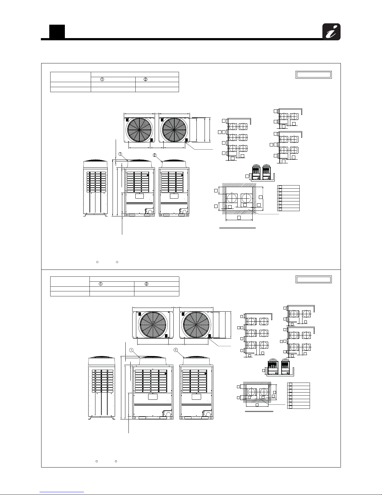
5
Outdoor unit
57
5-2-1-2. Combination
keep 19.7" in (500 mm) or more between the outdoor unit and traversing pipe if placing pipe
3. Draw out the pipe procured locally to the front of the outdoor unit horizontally, and
the bottom end of the outdoor unit.
2. Limit the height of the obstacle surrounding the outdoor unit to 31.5" in (800 mm) or less from
unit 78.7" in (2000 mm) apart from the obstacle.
1. If there is an obstacle at the upper side of the outdoor unit, set the top end of the outdoor
transversely.
(Note)
(Header unit Follower unit )
2
>
_
1
4. Arrange each outdoor unit in order of its capacity.
_
>
h
31.5"(800)
7.87"(200)
19.7"(500)
23.6"(600)
0.39"(10)
86.6"(2200)
70.1"(1780)
39.4"(1000)
>
_
c
>
e
f
g
_
>
_
>
d
_
_
>
>
_
a
b
_
>
(4-15×20)
(Anchor bolt hole pitch) (Anchor bolt hole pitch)
(Anchor bolt hole pitch)
(Including steady leg)
(Long hole)
(200)
7.87" or more
4-0.59"×0.79"
or more
19.3"
(490)
39.0"(990)
27.6"(700) 27.6"(700)
39.0"(990)
29.7"(755)
30.7"(780)
31.1"(790)
1.97"(50)
72.9"(1850)
3.35"(85)
62.8"(1595)
27.0"(687)
1.97"(50)
Two units connected
Outdoor unit
Header unit
Model name
MMY-AP1444FT9UL MMY-MAP0724FT9UL MMY-MAP0724FT9UL
Follower unit
MMY-MAP0724FT6ULMMY-MAP0724FT6ULMMY-AP1444FT6UL
(Unit:in (mm))
a a
e
f
e
d
c
Space required for service
Front side
(For work and service)
a
b
b a
e
f
( g )
(Note 3)
Front side Front side
Front side
Front side
Front side
Front side
a
b
( g )
(Note 3)
a a a
e
f
e
f
h
Front side Front side
Front side
Front side
Front side
Front side
_
>
h
31.5"(800)
7.87"(200)
19.7"(500)
23.6"(600)
0.39"(10)
95.3"(2420)
70.1"(1780)
39.4"(1000)
>
_
c
>
e
f
g
_
>
_
>
d
_
_
>
>
_
a
b
_
>
29.7"(755)
30.7"(780)
31.1"(790)
36.2"(920)
27.6"(700)
47.6"(1210)
39.0"(990)
(Including steady leg)
(Anchor bolt hole pitch)
(Long hole)
(4-15×20)
(Anchor bolt hole pitch) (Anchor bolt hole pitch)
(490)
(200)
7.87" or more
19.3" or more
4-0.59"×0.79"
72.9"(1850)
3.35"(85)
27.0"(687)
62.8"(1595)
1.97"(50)
1.97"(50)
Outdoor unit
Header unit
Model name
MMY-AP1684FT9UL MMY-MAP0964FT9UL MMY-MAP0724FT9UL
Follower unit
MMY-AP1684FT6UL MMY-MAP0964FT6UL MMY-MAP0724FT6UL
Two units connected
keep 19.7" in (500 mm) or more between the outdoor unit and traversing pipe if placing pipe
3. Draw out the pipe procured locally to the front of the outdoor unit horizontally, and
the bottom end of the outdoor unit.
2. Limit the height of the obstacle surrounding the outdoor unit to 31.5" in (800 mm) or less from
unit 78.7" in (2000 mm) apart from the obstacle.
1. If there is an obstacle at the upper side of the outdoor unit, set the top end of the outdoor
transversely.
(Note)
4. Arrange each outdoor unit in order of its capacity.
2
>
_
1
(Header unit Follower unit )
(Unit:in (mm))
( g )
(Note 3)
a baa a
f
e
e
f
h
Front side
Front side Front side
Front side
Front sideFront side
a a
d
e
f
c
e
Space required for service
(For work and service)
Front side
a
b
b
a
( g )
(Note 3)
e
f
Front side
Front side Front side
Front side
Front side Front side

5
Outdoor unit
58
Two units connected
Outdoor unit
Header unit
Model name
MMY-AP1924FT9UL MMY-MAP0964FT9UL MMY-MAP0964FT9UL
Follower unit
MMY-MAP0964FT6ULMMY-MAP0964FT6ULMMY-AP1924FT6UL
MMY-MAP1204FT9UL MMY-MAP0964FT9ULMMY-AP2164FT9UL
MMY-AP2164FT6UL MMY-MAP0964FT6ULMMY-MAP1204FT6UL
MMY-AP2404FT6UL
MMY-AP2404FT9UL MMY-MAP1204FT9UL
MMY-MAP1204FT6UL MMY-MAP1204FT6UL
MMY-MAP1204FT9UL
keep 19.7" in (500 mm) or more between the outdoor unit and traversing pipe if placing pipe
3. Draw out the pipe procured locally to the front of the outdoor unit horizontally, and
the bottom end of the outdoor unit.
2. Limit the height of the obstacle surrounding the outdoor unit to 31.5" in (800 mm) or less from
unit 78.7" in (2000 mm) apart from the obstacle.
1. If there is an obstacle at the upper side of the outdoor unit, set the top end of the outdoor
transversely.
(Note)
(Header unit Follower unit )
>
_
4. Arrange each outdoor unit in order of its capacity.
21
39.4"(1000)
70.1"(1780)
104.0"(2640)
d
h
g
e
31.5"(800)
0.39"(10)
c
b
a
_
23.6"(600)
19.7"(500)
>
>
_
_
>
>
_
_
>
>
_
>
_
7.87"(200)
>
_
f
29.7"(755)
30.7"(780)
31.1"(790)
36.2"(920)
36.2"(920)
19.3" or more
47.6"(1210)
47.6"(1210)
(Long hole)
(4-15×20)
(Anchor bolt hole pitch) (Anchor bolt hole pitch)
(Anchor bolt hole pitch)
(Including steady leg)
7.87 or more
(200)
(490)
4-0.59"×0.79"
72.9"(1850)
3.35"(85)
27.0"(687)
62.8"(1595)
1.97"(50)
1.97"(50)
(Unit:in (mm))
Front side
(For work and service)
Space required for service
d
a a
e
f
c
e
(Note 3)
Front side
Front sideFront side
Front side
Front side Front side
e
f
a
bb
( g )
a
Front side Front side
Front side
Front side Front side
Front side
(Note 3)
e
f
e
f
a
b
( g )
a aa
h
Three units connected
Front side
(For work and service)
29.7"(755)
30.7"(780)
31.1"(790)
36.2"(920)
72.9"(1850)
3.35"(85)
27.0"(687)
62.8"(1595)
1.97"(50)
36.2"(920)
20.1"(510)
(Note 3)
47.6"(1210)
47.6"(1210)
Space required for service
d
a a
e
f
h
c
e
a
bb
( g )
a
Front side
Front side
Front side
Front side
e
f
a
b
(Note 3)
( g )
a
aa
(Long hole)
(4-15×20)
(Anchor bolt hole pitch)
(Anchor bolt hole pitch)
(Anchor bolt hole pitch)
(Including steady leg)
7.87"(200)
or more
1.97"(50)
or more
4-0.59"×0.79"
2
36.2"(920)
20.1"(510)
47.6"(1210)
or more
7.87"(200)
or more
1
3
f
Front side
f
Front side
Front side
f
Front sideFront side
f
Front side
e
ff
e
Front side Front side
Front side
Front side Front side
Front sideFront side
Front side
Outdoor unit
Header unit
Model name
MMY-AP2884FT9UL MMY-MAP0964FT9UL
Follower unit
39.4"(1000)
70.1"(1780)
104.0"(2640)
d
h
g
e
31.5"(800)
0.39"(10)
c
b
a
_
23.6"(600)
19.7"(500)
>
>
_
_
>
>
_
_
>
>
_
>
_
7.87"(200)
>
_
f
MMY-MAP0964FT6ULMMY-AP2884FT6UL
MMY-MAP1204FT9ULMMY-AP3124FT9UL
MMY-AP3124FT6UL MMY-MAP1204FT6UL
MMY-AP3364FT6UL
MMY-AP3364FT9UL MMY-MAP1204FT9UL
MMY-MAP1204FT6UL
Follower unit
MMY-MAP0964FT9UL
MMY-MAP0964FT6UL
MMY-MAP0964FT9UL
MMY-MAP0964FT6UL
MMY-MAP1204FT9UL
MMY-MAP1204FT6UL
MMY-MAP0964FT9UL
MMY-MAP0964FT6UL
MMY-MAP0964FT9UL
MMY-MAP0964FT6UL
MMY-MAP0964FT9UL
MMY-MAP0964FT6UL
>
_
(Note)
1. If there is an obstacle at the upper side of the outdoor unit, set the top end of the outdoor
unit 78.7" in (2000 mm) apart from the obstacle.
2. Limit the height of the obstacle surrounding the outdoor unit to 31.5" in (800 mm) or less from
the bottom end of the outdoor unit.
3. Draw out the pipe procured locally to the front of the outdoor unit horizontally, and
keep 19.7" in (500 mm) or more between the outdoor unit and traversing pipe if placing pipe
transversely.
4. Arrange each outdoor unit in order of its capacity.
(Header unit Follower unit Follower unit)
5. Dimensional drawing of corrosion protection and corrosion heavy protection model is
the same as that of standard model.
>
_
1
2
3
1
2

5
Outdoor unit
59
5-2-2. Heat pump
5-2-2-1. Single unit
Model: MMY-MAP0724HT9UL, MAP0724HT6UL
72.9"

5
Outdoor unit
60
Model: MMY-MAP0964HT9UL, MAP0964HT6UL
MMY-MAP1144HT9UL, MAP1144HT6UL
72.9"

5
Outdoor unit
61
5-2-2-2. Combination
Model
Outdoor unit
(1) Header unit (2) Follower unit
MMY-AP1444HT9UL MMY-MAP0724HT9UL MMY-MAP0724HT9UL
MMY-AP1444HT6UL MMY-MAP0724HT6UL MMY-MAP0724HT6UL
19.3"
or more
(490)
Model
Outdoor unit
(1) Header unit (2) Follower unit
MMY-AP1684HT9UL MMY-MAP0964HT9UL MMY-MAP0724HT9UL
MMY-AP1684HT6UL MMY-MAP0964HT6UL MMY-MAP0724HT6UL
19.3" or more
(490)
95.3"(2420)
c

5
Outdoor unit
62
Model
Outdoor unit
(1) Header unit (2) Follower unit
MMY-AP1924HT9UL MMY-MAP0964HT9UL MMY-MAP0964HT9UL
MMY-AP1924HT6UL MMY-MAP0964HT6UL MMY-MAP0964HT6UL
MMY-AP2284HT9UL MMY-MAP1144HT9UL MMY-MAP1144HT9UL
MMY-AP2284HT6UL MMY-MAP1144HT6UL MMY-MAP1144HT6UL
19.3" or more
(490)
c

5
Outdoor unit
63
5-3. Center of gravity
Unit: in (mm)
Z
X
Z
X
Y
Y
(A)
(B)
Anchor bolt position
27.6” (700)
Anchor bolt position
36.2” (920)
Anchor bolt position
29.7” (755)
Anchor bolt position
29.7” (755)
Heat recovery
No. Model type
X
(in (mm))Y (in (mm))Z (in (mm))
Weight
(lbs (kg))
(A)
MAP0724FT9UL 19.3" (490) 14.6" (370) 26.8" (680) 583 (264)
MAP0724FT6UL 20.9'' (530) 15.7'' (400) 25.8'' (655) 658 (298)
(B)
MAP0964FT9UL
23.2" (590) 13.8" (350) 27.6" (700) 751 (340)
MAP1204FT9UL
MAP0964FT6UL
25.6'' (650) 15.4'' (390) 25.6'' (650) 826 (374)
MAP1204FT6UL
Heat pump
No. Model type
X
(in (mm))Y (in (mm))Z (in (mm))
Weight
(lbs (kg))
(A)
MAP0724HT9UL 19.7" (500) 15.4" (390) 25.4" (645) 546 (247)
MAP0724HT6UL 21.3'' (540) 15.8'' (400) 24.4'' (620) 621 (281)
(B)
MAP0964HT9UL
23.8" (605) 13.8" (350) 27.6" (700) 742 (336)
MAP1144HT9UL
MAP0964HT6UL
25.8'' (655) 15.4'' (390) 25.6'' (650) 817 (370)
MAP1144HT6UL

5
Outdoor unit
64
5-4. Branch header / branch joint
• Branch header (Heat recovery)
RBM-HY1043FUL, HY1083FUL, HY2043FUL, HY2083FUL
Unit: in (mm)
• Y-shape branch joint (Heat recovery)
RBM-BY55FUL, BY105FUL, BY205FUL, BY305FUL
Unit: in (mm)
Insulator
C
A
B
E
D
3.15" x
n
(80)
1.97"
(50)
Suction gas side
Insulator
C
A
B
E
D
3.15" x n
(80)
1.97"
(50)
Discharge gas side
Model A B C
DE
n Accessory socket Qty
RBM-HY1043FUL
Suction gas side 15.0" (380) 3.54" (90) 3.29" (83.6) 7/8" (22.2) 5/8" (15.9) 3
× 3, × 4, × 1, × 1
Discharge gas side 15.0" (380) 3.54" (90) 3.29" (83.6) 7/8" (22.2) 5/8" (15.9) 3
× 4, × 4, × 1, × 1
Liquid side 13.0" (330) 1.77" (45) – 5/8" (15.9) 3/8" (9.5) 3
× 4, × 1, × 1
RBM-HY1083FUL
Suction gas side 27.6" (700) 3.54" (90) 3.29" (83.6) 7/8" (22.2) 5/8" (15.9) 7
× 7, × 8, × 1, × 1
Discharge gas side 27.6" (700) 3.54" (90) 3.29" (83.6) 7/8" (22.2) 5/8" (15.9) 7
× 8, × 8, × 1, × 1
Liquid side 25.6" (650) 1.77" (45) – 5/8" (15.9) 3/8" (9.5) 7
× 8, × 1, × 1
RBM-HY2043FUL
Suction gas side 15.2" (385.5) 3.76" (95.5) 3.52" (89.3) 1-1/4" (31.8) 5/8" (15.9) 3
× 2, × 2, × 1, × 1
Discharge gas side 15.0" (380) 3.54" (90) 3.29" (83.6) 7/8" (22.2) 5/8" (15.9) 3
× 4, × 1
Liquid side 13.0" (330) 1.77" (45) – 5/8" (15.9) 3/8" (9.5) 3
× 2, × 1
RBM-HY2083FUL
Suction gas side 27.8" (705.5) 3.76" (95.5) 3.52" (89.3) 1-1/4" (31.8) 5/8" (15.9) 7
× 7, × 7, × 1, × 1
Discharge gas side 27.6" (700) 3.54" (90) 3.29" (83.6) 7/8" (22.2) 5/8" (15.9) 7
× 8, × 1
Liquid side 25.6" (650) 1.77" (45) – 5/8" (15.9) 3/8" (9.5) 7
× 7, × 1
Model A B
CD
Accessory socket Qty
RBM-BY55FUL
Suction gas side 6.30" (160) 3.15" (80) 5/8" (15.9) 5/8" (1 5.9)
× 2
Discharge gas side 6.30" (160) 3.15" (80) 5/8" (15.9) 5/8" (15.9)
× 3
Liquid side 5.12" (130) 2.76" (70) 3/8" (9.5) 3/8" (9.5)
× 2
RBM-BY105FUL
Suction gas side 6.69" (170) 3.15" (80) 7/8" (22.2) 7/8" (2 2.2)
× 2, × 2, × 1
Discharge gas side 6.69" (170) 3.15" (80) 7/8" (22.2) 7/8" (22.2)
× 1, × 2
Liquid side 6.30" (160) 3.15" (80) 5/8" (15.9) 5/8" (15.9)
× 1, × 1, × 1
RBM-BY205FUL
Suction gas side 7.87" (200) 3.15" (80) 1-1/4" (31.8) 1-1/8" (28.6)
× 1, × 1, × 2, × 1, × 1, × 1
Discharge gas side 6.69" (170) 3.15" (80) 7/8" (22.2) 7/8" (22.2)
× 2, × 2, × 1
Liquid side 6.30" (160) 3.15" (80) 5/8" (15.9) 5/8" (15.9)
× 1, × 1, × 1
Insulator
A
BB
E
D
D
2.40" (61)
2.93" (74.5)
3.15" x
n
(80)
Liquid side
6914
70
6918
85
169
6914
70
691885169
6927
59
9
70
1
51
6927
59
9
70
1
51
D
C
D
A
Insulator
B
D
C
D
A
Insulator
B
D
C
D
A
Insulator
B
Liquid side
Suction gas side Discharge gas side
9191
147091
189399192
1627435859
91
187093
95192

5
Outdoor unit
65
• Branching joint for connection of outdoor units (Heat recovery)
RBM-BT14FUL
Unit: in (mm)
Suction gas side
Discharge gas side
Liquid side
Model Accessory socket Qty
RBM-BT14FUL
Suction gas side
x 1, x 2, x 1
Discharge gas side
x 2, x 1, x 1
Liquid side
x 2, x 1
274359
192257
10
13

5
Outdoor unit
66
RBM-B24FUL
φ1-1/2"[38.1]
2.17"[55]
φ1-1/2"[38.1]
1.02"[26]
8.86"[225]
0.69"[17.5]
Heat insulator
L-pipe
Brazed locally
Heat insulator
φ1-1/8"
[28.6]
4.72"[120]
("6.89)[175]
2.56"
[65]
11.42"[290]
φ1-1/8"[28.6]
0.87"[22]
1.02"[26]
0.87"
[22]
R1.57"
[40]
Unit: in (mm)
Suction gas side
2.6"[66]
Ø1-1/4"[31.8]
Ø1-1/4"[31.8]
0.47"[12]
0.47"
[12]
0.47"
[12]
Ø1-1/4"
[31.8]
1.34"[34]
Discharge gas side
φ7/8"[22.2]
φ7/8"[22.2]
2.6"[66]
0.67"
[17]
0.67"
[17]
φ7/8"[22.2]
0.47"
[12]
1.1"[28]
Liquid side
Model Accessory socket Qty
RBM-BT14FUL
Suction gas side
× 1, × 2, × 1, × 1
Discharge gas side
× 1, × 2, × 1, × 1
Liquid side
× 2, × 1, × 1
436162
71
212327
59
141885

5
Outdoor unit
67
• Branch header (Heat pump)
RBM-HY1043UL, HY1083UL, HY2043UL, HY2083UL
Unit: in (mm)
• Y-shape branch joint (Heat pump)
RBM-BY55UL, BY105UL, BY205UL
Unit: in (mm)
Model A B C
DE
n Accessory socket Qty
RBM-HY1043UL
Gas side 15.0" (380) 3.54" (90) 3.29" (83.6) 7/8" (22.2) 5/8" (15.9) 3
× 4, × 4, × 1, × 1, × 1
Liquid side 13.0" (330) 1.77" (45) – 5/8" (15.9) 3/8" (9.5) 3
× 4, × 1, × 1
RBM-HY1083UL
Gas side 27.6" (700) 3.54" (90) 3.29" (83.6) 7/8" (22.2) 5/8" (15.9) 7
× 8, × 8, × 1, × 1, × 1
Liquid side 25.6" (650) 1.77" (45) – 5/8" (15.9) 3/8" (9.5) 7
× 8, × 1, × 1
RBM-HY2043UL
Gas side 15.2" (385.5) 3.76" (95.5) 3.52" (89.3) 1-1/4" (31.8) 5/8" (15.9) 3
× 2, × 2, × 1, × 1
Liquid side 13.0" (330) 1.77" (45) – 5/8" (15.9) 3/8" (9.5) 3
× 2
RBM-HY2083UL
Gas side 27.8" (705.5) 3.76" (95.5) 3.52" (89.3) 1-1/4" (31.8) 5/8" (15.9) 7
× 7, × 7, × 1, × 1
Liquid side 25.6" (680) 1.77" (45) – 5/8" (15.9) 3/8" (9.5) 7
× 7
RBM- A B
CD
Accessory socket Qty
BY55UL
Gas side 6.30" (160) 3.15" (80) 5/8" (15.9) 5/8" (15.9)
× 1, × 2, × 1
Liquid side 5.12" (130) 2.76" (70) 3/8" (9.5) 3/8" (9.5)
× 2
BY105UL
Gas side 6.69" (170) 3.15" (80) 7/8" (22.2) 7/8" (22.2)
× 21, × 2, × 1
Liquid side 6.30" (160) 3.15" (80) 5/8" (15.9) 5/8" (15.9)
× 1, × 1, × 1
BY205UL
Gas side 7.87" (200) 3.15" (80) 1-1/4" (31.8) 1-1/8" (28.6)
× 1, × 1, × 2, × 1, × 1, × 1
Liquid side 6.30" (160) 3.15" (80) 5/8" (15.9) 5/8" (15.9)
× 1, × 2, × 1
Insulator
3.15" x n
(80)
A
B
1.97"
(50)
Gas side
Insulator
2.93" (74.5)
2.40" (61)
3.15" x
n
(80)
A
BB
Liquid side
69141870
169
69141870
169
6927
59
1692759
1
Insulator
Liquid side
Insulator
Gas side
951911147091
99192
1627435859
91
95192

5
Outdoor unit
68
• Branching joint for connection of outdoor units (Set of two joints) (Heat pump)
RBM-BT14UL
RBM-BT14UL
Accessory socket Qty
Gas side
× 1, × 2, × 1,
Liquid side
× 2, × 1
Gas side
Unit: in (mm)
Liquid side
274359
10
13

5
Outdoor unit
69
• Accessory socket
1
16
Outer dia. Outer dia. Outer dia.
Outer dia.
Outer dia.
Outer dia.
ȭ1/4"
(6.4)
ȭ3/8"
(9.5)
ȭ5/8"
(15.9)
ȭ1-1/8"
(28.6)
0.94"
(24)
ȭ
ȭ7/8"
(22.2)
Sealed pipe
1.38"
(35)
1.38"
(35)
5/8"
(15.9)
ȭ3/8"
(9.5)
1.71"
(43.5)
1.58"
(40.2)
6
9
51
ȭ
ȭ
43
5885
ȭ3/4"
(19.1)
ȭ
10
13
27
59
ȭ
ȭ1-1/4"
(31.8)
Outer dia.
2.28"
(58)
ȭ3/8"
(9.5)
ȭ1/2"
(12.7)
ȭ5/8"
(15.9)
9291
Outer dia.
ȭ3/8"
(9.5)
ȭ5/8"
(15.9)
ȭ1/4"
(6.4)
ȭ1/2"
(12.7)
3.15"
(80)
141870
ȭ1/2"
(12.7)
ȭ7/8"
(22.2)
ȭ3/4"
(19.1)
2.72"(69)
.aid retuO.aid retuO
93 19 22 57
ȭ1/2"
(12.7)
Outer dia.
1.65"
(41.9)
ȭB
ȭ1"(25.4)
Outer dia.
A
A
B
1.93"
(49)
1-1/8"
(28.6)
2.32"
(59)
1-3/8"
(34.9)
27
59
A
B
1.42"
(36)
1/2"
(12.7)
1.30"
(33)
5/8"
(15.9)
10
13
A
B
1.26"
(32)
3/8"
(9.5)
1.10"
(28)
1/2"
(12.7)
1.48"
(37.5)
3/4"
(19.1)
6951
A
B
1.97"
(50)
5/8"
(15.9)
1.97"
(50)
7/8"
(22.2)
2.44"
(62)
1-3/8"
(34.9)
164358
Unit:in(mm)
A
B
1.57"
(40)
5/8"
(15.9)
1.57"
(40)
3/4"
(19.1)
2.13"
(54)
1-1/8"
(28.6)
1.61"
(41)
1/2"
(12.7)
141870
85
A
B
1.81"
(46)
3/4"
(19.1)
1.73"
(44)
7/8"
(22.2)
2.05"
(52)
1-1/8"
(28.6)
192257

5
Outdoor unit
70
5-5. Refrigerant cycle diagram
5-5-1. Heat recovery
Model: MMY-MAP0724FT*
Fusible plug
FP
FP
Solenoid
Tube JointValve Valve
DistributorCapillaryCheckCheckStrainer
FM
SV
(TL)
PMV1
4-way Valve
Hi
A
ccumulato
r
(TS1)
(SV2䠅
(TE1)
(
SV3D
)
PMV2
(SV3B)
(SV3A)
(TD1)
(TK4)
(SV3E)
(TK5)
Oil header
Propeller fan
Liquid
tank
(TE2)
(SV6)
(TO)
(SV3C)
Oil
Separator
Compressor 1
(Inverter)
(Right side)
Main heat exchanger
Fan motor
SV
(SV5䠅
Sub-heat exchanger (Right side)
(Left Side)
Main heat exchanger
Sub-heat exchanger (Left side)
SV
(TD2)
High
pressure
SW
(SV42)
(TK2)
SV
(SV41)
(TK1)
SV
High
pressure
SW
SV
SV
SV
SV
SV
SV
SV
(SV11)
(TS2)
Check
Joint
(Liquid)
Check joint (high pressure)
Check joint
(low pressure)
PMV4
Compressor 2
(Inverter)
Symbol
High pressure sensor
Liquid
side
service
valve
Discharge
side
service
valve
Suction
side
service
valve
balance
pipe
service
valve
Temperature
Sensor
Low pressure
sensor
Fusible plug
SV
(SV14)

5
Outdoor unit
71
Model: MMY-MAP0964FT*, MMY-MAP1204FT*
Fusible plug
FP
FP
DistributorCapillaryCheckCheckStrainer
Valve
Solenoid
Tube JointValve
FM
(TL)
PMV1
(TS1)
㻔SV2䠅
(TE1)
(
SV3D
)
PMV2
(SV3B)
(SV3A)
(TD1)
(TK4)
(SV3E)
(TK5)
PMV4
(TE2)
(TD3)
(
SV43
)
(TK3)
(SV6)
(TO)
(SV3F)
(SV3C)
SV
(SV5䠅
SV
SV
SV
(TD2)
(
SV42
)
(TK2)
SV
(
SV41
)
(TK1)
SV
SV
SV
SV
SV
SV
SV
SV
SV
SV
(SV11)
(TS2)
Propeller fan
(Right side)
Main heat exchanger
Fan motor
Sub-heat exchanger (Right side)
(Left Side)
Main heat exchanger
Sub-heat exchanger (Left side)
4-way Valve
A
ccumulato
r
High pressure sensor
Check joint (high pressure)
Oil
Separator
Liquid
tank
High
pressure
SW
High
pressure
SWHigh
pressure
SW
Compressor 1
(Inverter)
Compressor 2
(Inverter)
Compressor 3
(Inverter)
Oil
header
Check
Joint
(Liquid)
Symbol
Low pressure
sensor
Check joint
(low pressure)
Liquid
side
service
valve
Discharge
side
service
valve
Suction
side
service
valve
balance
pipe
service
valve
Temperature
Sensor
Fusible plug
SV
(SV14)

5
Outdoor unit
72
5-5-2. Heat pump
Model: MMY-MAP0724HT*
(TL)
PMV1
(TD2)
(TS1)
(SV2)
(SV5)
(TE1)
M
(SV3D)
PMV2
(
TK2
)
(SV3B)
(
TK1
)
(SV3A)
(TD1)
(TK4)
(SV3E)
(
TK5
)
A
3
(
SV3C)
(TO)
SV
SV
SV
SV
SV
SV
SV
SV
SV
SV
FP
(SV41) (SV42)
FP
Fan
4-way valve
Right side
Heat exchanger
Left side
Heat exchanger
Fusible
plug
Check valve
Check valve
Liquid side
packed valve
Gas side
service valve
Balance pipe
packed valve
Liquid tank
Reducer
Low-pressure sensor
Fusible
plug
Accumulator
Check
valve
High-pressure
switch
Check
valve
Oil header
Check
valve
High-pressure
switch
Oil separator
Compressor
2
(Inverter)
Compressor
1
(Inverter)
Solenoid
valve
Capillary
tube
Check
valve
Check joint
Strainer
Temperature
sensor
Distributor
Symbol
High-pressure sensor
Check valve
Fan motor
Check
valve

5
Outdoor unit
73
Model: MMY-MAP0964HT*, MMY-MAP1144HT*
(TL)
PMV1
(TD2)
(TS1)
(SV2)
(TE1)
M
(
SV3D
)
PMV2
(TK2)
(SV3B)
(TK1)
(SV3A)
(TD1)
(TK4)
(SV3E)
(TK5)
(SV41)
(SV42)
PMV4
(TE2)
(TD3)
(SV43)
(TK3)
(SV6)
(TO)
(SV3F)
(SV3C)
SV
SV
SV
SV
SV
SV
SV
SV
SV
SV
S
V
FP
SV
FP
Fan
4-way valve
Right side
Main heat exchanger
Left side
Main heat exchanger
Fusible
plug
Check valve
Check valve
Liquid side
packed valve
Gas side
service valve
Balance pipe
packed valve
Liquid tank
Low-pressure sensor
Fusible
plug
Accumulator
High-pressure
switch
Oil header
High-pressure
switch
Oil separator
Solenoid
valve
Capillary
tube
Check
valve
Check joint
Strainer
Temperature
sensor
Distributor
Symbol
High-pressure sensor
Fan motor
Sub heat exchanger at right side
Sub heat exchanger at left side
Check valve
Check valve
Highpressure
switch
Compressor
2
(Inverter)
Compressor
1
(Inverter)
Compressor
3
(Inverter)

5
Outdoor unit
74
5-6. Wiring diagram
5-6-1. Heat recovery
Model: MMY-MAP0724FT9UL (208 / 230 V, 60 Hz)

5
Outdoor unit
75
Model: MMY-MAP0724FT6UL (460 V, 60 Hz)
(WHI) (WHI) (WHI)
PUR

5
Outdoor unit
76
Model: MMY-MAP0964FT9UL, MAP1204FT9UL (208 / 230 V, 60 Hz)

5
Outdoor unit
77
Model: MMY-MAP0964FT6UL, MAP1204FT6UL (460 V, 60 Hz)
(WHI)(WHI)(WHI)
PUR

5
Outdoor unit
78
5-6-2. Heat pump
Model: MMY-MAP0724HT9UL

5
Outdoor unit
79
Model: MMY-MAP0724HT6UL
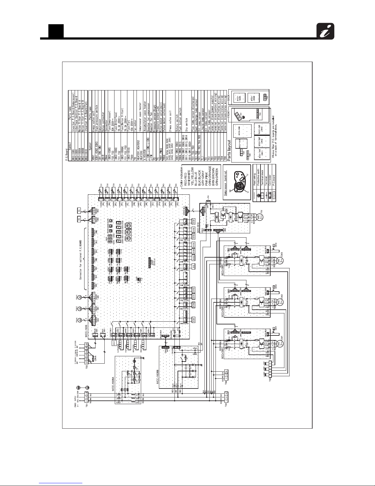
5
Outdoor unit
80
Model: MMY-MAP0964HT9UL, MAP1144HT9UL

5
Outdoor unit
81
Model: MMY-MAP0964HT6UL, MAP1144HT6UL

5
Outdoor unit
82
5-7. Connecting diagram
5-7-1. Heat recovery
5-7-2. Heat pump
Outdoor unit (Follower unit)
Outdoor unit (Header unit)
Indoor unit
Flow selector unit (FS unit)
Remote control
Central remote control (option)
Circuit breaker
Disconnect switch per NEC
W1 : Shielded control wiring between indoor and outdoor units
W2 : Shielded control wiring between indoor units
W3 : Shielded control wiring between outdoor units
W4 : Shielded central control wiring
3㹼60 Hz 208/230 V
3㹼60 Hz 460 V
Outdoor unit
power supply
Open
W3
W1
W2
Indoor unit
power supply
1㹼60 Hz 208/230 V
Central control
power supply
1㹼60 Hz 120 V
(Note)
1. When using a central control, plug in the conne ctor between [U1,U2] and [U3,U4] terminal of the header
unit.
2. Connect the shield of all control wiring to the control ground screw on every unit. (Indoor & Outdoor)
3. Group control.
4. Power supply wiring to be per NEC and loc al codes.
5. For the control wires connecting indoor uni ts, outdoor units, and between indoor and outdoor units, use 2core shielded wires.
6. For additional details, see the individual unit wi ring diagrams. (Indoor & Outdoor)
7. Control wire and power line wire between FS unit a nd indoor unit are the accessory parts of FS unit.
(Wire length: 20 ft (6 m)
If the length between indoor and FS unit exceeds 16 ft (5 m), connect by usin g the connection cable kit sold
separately (RBC-CBK15FUL)
Connect the connector of control wiring on the indoor P.C. board, and so as the power supply wire to L and
N terminals.
8. When connecting the multiple indoor u nits to a single FS unit, only group control is available.
For the indoor unit, a remote control cannot be ind ividually connected.
3㹼60 Hz 208/230 V
3㹼60 Hz 460 V
Outdoor unit
power supply

5
Outdoor unit
83
5-8. Applied control for outdoor unit
5-8-1. Outdoor fan high static pressure shift
Purpose / characteristics
This function is used when connecting a duct to the discharge port of an outdoor unit (as part of, for example, unit
installation on the floor by floor installation.)
Setup
Turn ON the DIP switch [SW10, Bit 2] provided on the interface P.C. board of the outdoor unit.
This function must be enabled with every discharge duct connected outdoor unit for both of the header and follower
units.
Specification
Increase the speed of the propeller fan units on the outdoor fan to allow the installation of a duct with a maximum
external static pressure not greater than specified in the table below. If a discharge duct with a resistance greater
than 0.06 InWG (15 Pa) is to be used, enable this function. The maximum external static pressures of base units are
shown below (Table 1, 3).
Table 1: Maximum External Static Pressures of Base Outdoor Units
(*) Calculate duct resistance from outdoor unit air flow.
Table 2: Maximum External Static Pressures for Combined Use of Base Units
Heat
recovery
Model MMY- MAP0724FT9UL/6UL MAP0964FT9UL/6UL MAP1204FT9UL/6UL
Maximum external static pressure 0.20 InWG 0.16 InWG 0.16 InWG
(*) Outdoor unit air flow (CFM) 5120 7060 7620
Heat
recovery
Capacity
type
Model name Combination of outdoor units
Maximum external
static pressure (in WG)
MMY- Unit 1 Unit 2 Unit 3
208/230 V model
072 MAP0724FT9UL MAP0724FT9UL – – 0.20
096 MAP0964FT9UL MAP0964FT9UL – – 0.16
120 MAP1204FT9UL MAP1204FT9UL – – 0.16
144 AP1444FT9UL MAP0724FT9UL MAP0724FT9UL – 0.20
168 AP1684FT9UL MAP0964FT9UL MAP0724FT9UL – 0.16
192 AP1924FT9UL MAP0964FT9UL MAP0964FT9UL – 0.16
216 AP2164FT9UL MAP1204FT9UL MAP0964FT9UL – 0.16
240 AP2404FT9UL MAP1204FT9UL MAP1204FT9UL – 0.16
288 AP2884FT9UL MAP0964FT9UL MAP0964FT9UL MAP0964FT9UL 0.16
312 AP3124FT9UL MAP1204FT9UL MAP0964FT9UL MAP0964FT9UL 0.16
336 AP3364FT9UL MAP1204FT9UL MAP1204FT9UL MAP0964FT9UL 0.16
460 V model
072 MAP0724FT6UL MAP0724FT6UL – – 0.20
096 MAP0964FT6UL MAP0964FT6UL – – 0.16
120 MAP1204FT6UL MAP1204FT6UL – – 0.16
144 AP1444FT6UL MAP0724FT6UL MAP0724FT6UL – 0.20
168 AP1684FT6UL MAP0964FT6UL MAP0724FT6UL – 0.16
192 AP1924FT6UL MAP0964FT6UL MAP0964FT6UL – 0.16
216 AP2164FT6UL MAP1204FT6UL MAP0964FT6UL – 0.16
240 AP2404FT6UL MAP1204FT6UL MAP1204FT6UL – 0.16
288 AP2884FT6UL MAP0964FT
6UL MAP0964FT6UL MAP0964FT6UL 0.16
312 AP3124FT6UL MAP0964FT6UL MAP0964FT6UL MAP0964FT
6UL 0.16
336 AP3364FT6UL MAP1204FT6UL MAP1204FT6UL MAP0964FT6UL 0.16

5
Outdoor unit
84
Table 3: Maximum External Static Pressures of Base Outdoor Units
(*) Calculate duct resistance from outdoor unit air flow.
Table 4: Maximum External Static Pressures for Combined Use of Base Units
5-8-2. Priority operation mode setting (SMMS-i (Heat pump) only)
Purpose / characteristics
This function allows switching between priority cooling and priority heating.
Four patterns of priority operation mode setting are available as shown in the table below. Select a suitable priority
mode according to the needs of the customer.
Setup
CAUTION
In the case of the priority indoor unit mode, it is necessary to set up the specific indoor unit chosen for priority operation
(a single unit only).
(1) Outdoor unit setup method (header unit)
Heat
pump
Model MMY- MAP0724HT6UL MAP0964HT6UL MAP1144HT6UL
Maximum external static pressure 0.2 InGW (50 Pa) 0.2 InGW (50 Pa) 0.2 InGW (50 Pa)
(*) Outdoor unit air flow (CFM) 5800 6600 7060
Heat
pump
Capacity
type
Model name Combination of outdoor units
Maximum external
static pressure (in WG)
MMY- Unit 1 Unit 2
208/230 V model
072 MAP0724HT9UL MAP0724HT9UL 0.20
096 MAP0964HT9UL MAP0964HT9UL 0.20
114 MAP1144HT9UL MAP1144HT9UL 0.20
144 AP1444HT9UL MAP0724HT9UL MAP0724HT9UL 0.20
168 AP1684HT9UL MAP0964HT9UL MAP0724HT9UL 0.20
192 AP1924HT9UL MAP0964HT9UL MAP0964HT9UL 0.20
228 AP2284HT9UL MAP1144HT9UL MAP1144HT9UL 0.20
460 V model
072 MAP0724HT6UL MAP0724HT6UL 0.20
096 MAP0964HT6UL MAP0964HT6UL 0.20
114 MAP1144HT6UL MAP1144HT6UL 0.20
144 AP1444HT6UL MAP0724HT6UL MAP0724HT6UL 0.20
168 AP1684HT6UL MAP0964HT6UL MAP0724HT6UL 0.20
192 AP1924HT6UL MAP0964HT6UL MAP0964HT6UL 0.20
228 AP2284HT6UL MAP1144HT6UL MAP1144HT6UL 0.20
SW11
Operation
Bit 1 Bit 2
OFF OFF Priority heating (factory default)
ON OFF Priority cooling
OFF ON
Priority operation based on No. of units in operation (priority given to the operation mode with the
largest share of units in operation)
ON ON
Priority indoor unit (priority given to the operation mode of the specific indoor unit set up for priority
operation)

5
Outdoor unit
85
(2) Indoor unit setup method for priority indoor unit mode
The setting can be changed only when the system is at rest. (Be sure to turn
off the system prior to this operation.)
1 Push the + + buttons simultaneously and hold for at least
4 seconds. The display window will start flashing in a little while.
Verify that the displayed CODE No. is 10.
• If the displayed CODE No. is not 10, press the button to erase the
display and repeat the procedure from the beginning.
(Note that the system does not respond to remote control operation for
about 1 minute after the button is pushed.)
(In the case of group control, the indoor unit No. displayed first indicates
the header unit.)
2 Each time the button is pushed, one of the indoor
unit Nos. under group control is displayed in turn. Select
the indoor unit whose setting is to be changed.
The fan and louver of the selected indoor unit then come on, so
that the position of this unit can be confirmed.
3 Use the button to select the CODE No. 04.
4 Use the button to select the SET DATA 0001.
Priority set 0001 No priority set 0000
5 Push the button.
The setup is finished when the display changes from flashing to steady.
6 Upon finishing the setup, push the button. (This
finalizes the setting.)
When the button is pushed, the display goes blank, and the
system returns to normal off state.
(Note that the system does not respond to remote control
operation for about 1 minute after the button is pushed.)
NOTE
Priority can be given to only one indoor unit. If more than one indoor unit is accidentally set to priority, an error code
(L5 or L6: Duplicated indoor unit priority setting) will be displayed.
All units displaying L5 have been set to 0001 (priority). Keep the unit to which priority should be given as it is, and
change the value back to 0000 (no priority) for all the rest.
Error code Description
Duplicated indoor unit priority setting (The unit is set to 0001.)
Duplicated indoor unit priority setting (The unit is set to 0000.)
SET
TIME
TIMER SET
TEST
FILTER
RESET
TEMP.
CL
FAN
SAVE
SWING/FIX
VENT
MODE
ON / OFF
UNIT LOUVER
54
126
3
UNIT LOUVER

5
Outdoor unit
86
5-9. Optional PCB of outdoor unit
Model
name
Appearance Function
TCB-PCDM4UL
Size: 2.80 × 3.35 (in)
Power peak-cut Control
Application
* Install the optional
PCB in the inverter
assembly of the
outdoor header unit.
Standard Specifications
(Wiring example)
<SW07 (bit 2) OFF [2-stage switching]>
Input SW07 (bit 1)
Display relay
(L1)
SW1 SW2 Bit 1 OFF Bit 1 ON
OFF ON
100% (normal
operation)
100% (normal
operation)
OFF
ON OFF 0% (forced stop)
Approx. 60% (upper
limit regulated)
ON
PJ17
CN513
SW07
TB1
[ON]
[OFF]
TB2
COM
ON
COM
OFF
Bit 2 OFF
L1
SW1
SW2
SW2
SW 1
ON
OFF
1234
Outdoor unit
interface PCB
Connection cable (attached in this optional PCB)
Locally procured
Power
supply
[OPERATION]
L1: Display lamp during power peak cut control
Optional PCB
Header outdoor unit
Display
relay
Shield
wire
Shield
wire
For SW1 and SW2, be sure to provide no-voltage
contacts for each terminal.
The input signals of SW1 and SW2 may be pulse
input (100 msec or more) or continuous make.
Do not turn on [SW1] and [SW2] simultaneously.
For one input function
<SW07 (bit 2) OFF [2-stage switching]>
Jumper
lead J16
Input
SW1
SW07 (bit 1)
Display relay
(L1)
Bit 1 OFF Bit 1 ON
Cut
OFF
100% (normal
operation)
100% (normal
operation)
OFF
ON 0% (forced stop)
Approx. 60%
(upper limit
regulated)
ON
PJ17
TB1
TB2
COM
ON
COM
OFF
CN513
SW07
Bit 2 ON
L1
SW 1
ON
OFF
1234
[ON]
[OFF]
Outdoor unit
interface PCB
Connection cable (attached in this optional PCB)
Locally procured
Power
supply
[OPERATION]
L1: Display lamp during power peak cut control
Optional PCB
Header outdoor unit
Display
relay
J16 Cut
Shield
wire
Shield
wire
Power peak-cut ON-OFF control is made possible on the SHRM-i on
only the [ON] terminal input (SW1) by cutting the jumper lead (J16) of the
center outdoor unit interface PCB.
(Wiring example)
Power peak-cut control turns ON when SW1 in the wiring example is ON
(continuous make).

5
Outdoor unit
87
Model
name
Appearance Function
TCB-PCDM4UL
Size: 2.80 × 3.35 (in)
Application
* Install the optional
PCB in the inverter
assembly of the
outdoor header unit.
Enhanced Specifications
(Wiring example)
<SW07 (bit 2) ON [4-stage switching]>
Input SW07 (bit 1)
Display relay
(L1)
SW1 SW2 Bit 1 OFF Bit 1 ON
OFF OFF
100% (normal
operation)
100% (normal
operation)
OFF
ON OFF
Approx. 80% (upper
limit regulated)
Approx. 85% (upper
limit regulated)
ON
OFF ON
Approx. 60% (upper
limit regulated)
Approx. 75% (upper
limit regulated)
ON
ON ON 0% (forced stop)
Approx. 60% (upper
limit regulated)
ON
PJ17
TB1
[ON]
[OFF]
TB2
COM
ON
COM
OFF
CN513
SW07
Bit 2 ON
L1
SW 1
ON
OFF
1234
SW 2
Outdoor unit
interface PCB
Connection cable (attached in this optional PCB)
Locally procured
Power
supply
[OPERATION]
L1: Display lamp during power peak cut control
Optional PCB
Header outdoor unit
Display
relay
Shield
wire
Shield
wire
For SW1 and SW2, be sure to
provide no-voltage contacts for
each terminal.

5
Outdoor unit
88
Model
name
Appearance Function
TCB-PCMO4UL
Size: 2.19 × 2.35 (in)
[1] External master ON/OFF control
Application
* Install the optional
PCB in the inverter
assembly of the
outdoor header unit.
[2] Night time operation (sound reduction) control
Function
Operation
SW1: Operation input switch
SW2: Stop input switch
Terminal Input Signal Operation
COOL (SW1)
ON
OFF
All indoor units operate together
HEAT (SW2)
ON
OFF
All indoor units stop together
7
1JP
CN512
TB1
SW1
SW2
COM
HEAT
COOL
Locally procured
Optional PCB
Shield
wire
Outdoor unit
interface PCB
Connection cable
(attached in this
optional PCB)
Header outdoor unit
ontacts for each terminal.
By connecting the cable (attached in this optional PCB) to the
interface PC board on an outdoor unit, all indoor units connected to
the outdoor unit enable to operate simultaneously.
The outdoor unit connection is for the header unit (U1).
Provide no-voltage pulse contacts for each terminal.
Hold the ON state for at least 100 msec.
Do not turn SW1 and SW2 ON simultaneously
Function
Operation
Sound reduction and approximation capacity (reference)
The outdoor unit connection is for the header unit (U1).
SW1: Night time signal switch
Each terminal should be connected to dry contact.
Terminal Input Signal Operation
COOL (SW1)
ON
OFF
Night time operation control
ON
OFF
Normal operation
71JP
TB1
SW1
COM
HEAT
COOL
Outdoor unit
interface PCB
Connection cable
(attached in this
optional PCB)
Locally procured
Optional PCB
Shield
wire
Header outdoor unit
CN508
Outdoor unit
(base unit)
During low-noise
mode* dB(A)
Capacity
Cooling Heating
072 type 50 approx. 85% approx. 80%
096 type 53 approx. 85% approx. 85%
Relative to maximum capacity
114/120 type 53 approx. 80% approx. 80%
* Position of noise measuring device:
3.3 ft (1 m) from the front face of the set and 4.9 ft (1.5 m)
above ground (anechoic sound)
As the cable (attached in this optional PCB) is connected to the “Interface
PCB” on an outdoor unit, both compressor speed and fan speed are
restricted while the signal of the night operation control is input. It
makes the noise reduction during the night time operation.

5
Outdoor unit
89
Model
name
Appearance Function
TCB-PCMO4UL
Size: 2.19 × 2.35 (in)
[3] Operation mode selection control
Application
* Install the optional
PCB in the inverter
assembly of the
outdoor header unit.
Function
The heating/cooling mode of the system can be selected by connecting
to the interface PCB of outdoor units.
Operation
The outdoor unit connection is for the header unit (U1).
SW1: Cooling mode specified input switch
SW2: Heating mode specified input switch
71JP
TB1
SW1
SW2
COM
HEAT
COOL
Outdoor unit
interface PCB
Connection cable
(attached in this
optional PCB)
Locally procured
Optional PCB
Shield
wire
Header outdoor unit
Each terminal should be connected to dry contact.
Input Signal
Operation: Selected operation
mode
Cooling (SW1) Heating (SW2)
ON OFF Cooling operation only
OFF ON Heating operation only
OFF OFF Normal operation
CN510
The Switching of processing of Indoor Unit Operation State
Processing of the operation state can be switched for indoor units in a
mode other than the selected operation mode by setting the jumper lead
(J01) of the header outdoor unit interface PCB.
Jumper
lead
Details of Processing
J01
connected
(factory
default)
Unallowed indoor units in a mode other than the selected
operation mode are not treated as priority (thermo OFF state).
(Unallowed indoor units)
J01 cut
Indoor units in a mode other than the selected operation mode
are forcibly switched to the selected operation mode.
Operation
Mode
Operation State
Remote
control
Cooling
unit
Air blow operation at blow rate
set on remote control
,
indicator is
displayed.
Heating
unit
Air blow operation at super-slow
blow rate
Air blow
unit
Regular air blow operation at
blow rate set on remote control
PC board
selection mode
Remote control operation/display
Normal
, , , or can be
selected
When using the
remote control,
(mode select
control) indicator
is displayed.
Cool
Only , , or can
be selected
Heat
Only or can be
selected

5
Outdoor unit
90
Model
name
Appearance Function
TCB-PCMO4UL
Size: 2.19 × 2.35 (in)
[4] Snowfall fan control
Application
* Install the optional
PCB in the inverter
assembly of the
outdoor header unit.
Model
name
Appearance Function
TCB-PCIN4UL
Size: 2.87 × 3.11 (in)
[1] Error / Operation Output
Application
* Install the optional
PCB in the inverter
assembly of the
outdoor header unit.
Function
The outdoor unit fan operates at snowfall by connecting to the outdoor
unit interface PCB.
Operation
SW1: Snowfall detection switch (snowfall sensor)
Provide no-voltage continuous contacts for each terminal.
Terminal Input Signal Operation
Cooling (SW1)
ON
OFF
Snowfall fan control (Fan in
outdoor unit operates.)
ON
OFF
Normal operation
71JP
TB1
SW1
COM
HEAT
COOL
Locally procured
Optional PCB
Snowfall sens or
Shield
wire
Outdoor unit
interface PCB
Connection cable
(attached in this
optional PCB)
Header outdoor unit
CN509
Function
The operation error output PCB can indicate operation and error states
by connecting to the interface PCB of outdoor units.
Operation
Operation output: The operation indicator is on while any indoor unit in
the system is operating.
Error output: The error indicator is on when an error is occurred on
even one of the indoor or outdoor units in the system.
Wiring example
* [OUTPUT3] is displayed when power is turned on.
C1 Attached connection cable 1 (4wires)
CN511 Connector on interface side (green)
K1, K2 Relays
L1 Error indication Lamp
L2 Operation indication Lamp
OUTPUT1 Error output
OUTPUT2 Operation output
PJ20 Connector on optional PCB side
PS Power supply unit
TB1 Terminal block
OUTPUT1
PJ20
OUTPUT2
OUTPUT3
TB1
L1
L2
1
2
5
6
4
3
C1
PS
PS
K1
K2
1
ON
OFF
234
SW16
Outdoor unit
interface PCB
Optional PCB
Locally procured
Header outdoor unit
Shield
wire
CN511

5
Outdoor unit
91
Model
name
Appearance Function
TCB-PCIN4UL
Size: 2.87 × 3.11 (in)
[2] Compressor Operation Output
Application
* Install the optional
PCB in the inverter
assembly of individual
outdoor unit.
Function
While each compressor in the outdoor unit is running, the compressor
operation signal is displayed. This function can also be used to measure
the elapsed time for the compressor operation.
Operation
While a compressor is in operation, the relay of the
output terminal corresponding to the compressor turns
on (closed). When the operation of a compressor is off,
the relay turns off (opened).
The output terminals are “OUTPUT1”, “OUTPUT2”
and “OUTPUT3” from left to right of the compressors facing to the
front of the outdoor unit.
Wiring example
1 2
3
1 2
OUTPUT1
PJ20
OUTPUT2
OUTPUT3
TB1
1
2
5
6
4
3
C2
K1
K2
K3
1
ON
OFF
234
SW16
CTR1
CTR2
CTR3
L1
PS
L2 PS
L3
PS
Outdoor unit
interface PCB
Optional PCB
Locally procured
Outdoor unit
Shield
wire
C2 Attached connection cable 2 (5wires)
CN514 Connector on interface side (green)
CTR1 Elapsed operation counter 1
CTR2 Elapsed operation counter 2
CTR3 Elapsed operation counter 3
K1, K2, K3 Relays
L1, L2, L3 Operation indication LEDs
OUTPUT1 Compressor 1 operation output terminal
OUTPUT2 Compressor 2 operation output terminal
OUTPUT3 Compressor 3 operation output terminal
PJ20 Connector on optional PCB side
PS Power supply unit
TB1 Terminal block
CN514

5
Outdoor unit
92
Model
name
Appearance Function
TCB-PCIN4UL
Size: 2.87 × 3.11 (in)
[3] Operating Rate Output
Application
* Install the optional
PCB in the inverter
assembly of the
outdoor header unit.
Function
The state of operation is available to check remotely as the signal of
system operation rate enable to output.
Operation
As shown in the table, each of the output terminals turns ON (relay
closes) and OFF (relay opens) depending on the system operating rate.
OFF=relay open ON=relay closed
Wiring example
Functions SW16
OUTPUT1 OUTPUT2 OUTPUT3 Operating rate FA
System
operating
rate output
bit 1: ON
bit 2: OFF
OFF OFF OFF FA = 0%
ON OFF OFF 0% < FA < 20%
OFF ON OFF 20% ≤ FA < 35%
ON ON OFF 35% ≤ FA < 50%
OFF OFF ON 50% ≤ FA < 65%
ON OFF ON 65% ≤ FA < 80%
OFF ON ON 80% ≤ FA < 95%
ON ON ON 95% ≤ FA
C2 Attached connection cable 2 (5wires)
CN514 Connector on interface side (green)
K1, K2, K3 Relays
MONITOR Monitoring device
OUTPUT1 Output terminal for each function
OUTPUT2 Output terminal for each function
OUTPUT3 Output terminal for each function
PJ20 Connector on optional PCB side
TB1 Terminal block
1
ON
OFF
234
OUTPUT1
PJ20
OUTPUT2
OUTPUT3
TB1
1
2
5
6
4
3
C2
K1
K2
K3
1
ON
OFF
234
SW16
MONITOR
Outdoor unit
interface PCB
Optional PCB
Locally procured
Header outdoor unit
Shield
wire
CN514

5
Outdoor unit
93
Dimensions of P.C. board
Unit: in (mm)
TCB-PCDM4UL
TCB-PCMO4UL
TCB-PCIN4UL
TCB-PCNT31TLUL
Terminal
Screw M3 6
2.8" (71)
2.4" (61)
Terminal
Screw M4 8
4-ø0.16" (4) hole
3.35" (85)
2.95" (75)
OFF
OFF ON
MS
10
MS
OFF
COM COMON
ON
T82
T81
K100
PJ17
5
5
ICI
41
8
OPERATION
/
TOSHI BA
NCC-1212
Terminal
Screw M3 6
PJ17
TOSH IBA
NCC-1214
5
41
ICI
41
D2
HEAT
COMCOOL
10
TB1
8
2.19" (55.5)
1.79" (45.5)
2.36" (60)
1.97" (50)
4-ø0.16" (4) hole
C4
C2
C3
K1
12
OUTPUT1 OUTPUT2 OUTPUT3
34 56
K2
1
PJ20
5
K3
TB1
MCC-1613- 02
3D2D1D
2.48" (63)
2.87" (73)
2.72" (69)
3.11" (79)
4-
ø0.16" (4) hole
Ter m in al blo ck (M3)
2.05" (52)
3.35" (85)

5
Outdoor unit
94
5-10. Sound pressure level data
5-10-1. Heat recovery
Outdoor unit
1 Single unit
Microphone
4.92 ft (1.5 m)
3.28 ft (1 m)
NC-70
NC-60
NC-50
NC-40
NC-30
NC-20
MMY-MAP0724FT9UL/6UL
56 57
Sound pressure level (dB (A))
Cooling Heating
Octave band sound pressure level (d B)
Octave band center frequency (Hz)
10
20
30
40
50
60
70
80
90
63 125 250 500 1000 2000 4000 8000
Cooling
Heating
Audibility limits of
continuous white noise
NC-70
NC-60
NC-50
NC-40
NC-30
NC-20
MMY-MAP0964FT9UL/6UL
62 63
Sound pressure level (dB (A))
Cooling Heating
Octave band sound pressure level (d B)
Octave band center frequency (Hz)
10
20
30
40
50
60
70
80
90
63 125 250 500 1000 2000 4000 8000
Cooling
Heating
Audibility limits of
continuous white noise
NC-70
NC-60
NC-50
NC-40
NC-30
NC-20
MMY-MAP1204FT9UL/6UL
63.5 65.5
Sound pressure level (dB (A))
Cooling Heating
Octave band sound pressure level (d B)
Octave band center frequency (Hz)
10
20
30
40
50
60
70
80
90
63 125 250 500 1000 2000 4000 8000
Cooling
Heating
Audibility limits of
continuous white noise

5
Outdoor unit
95
2 Combination
NC-70
NC-60
NC-50
NC-40
NC-30
NC-20
MMY-AP1444FT9UL/6UL
59 60
Sound pressure level (dB (A))
Cooling Heating
Octave band sound pressure level (d B)
Octave band center frequency (Hz)
10
20
30
40
50
60
70
80
90
63 125 250 500 1000 2000 4000 8000
Cooling
Heating
Audibility limits of
continuous white noise
NC-70
NC-60
NC-50
NC-40
NC-30
NC-20
MMY-AP1684FT9UL/6UL
63 64
Sound pressure level (dB (A))
Cooling Heating
Octave band sound pressure level (d B)
Octave band center frequency (Hz)
10
20
30
40
50
60
70
80
90
63 125 250 500 1000 2000 4000 8000
Cooling
Heating
Audibility limits of
continuous white noise
NC-70
NC-60
NC-50
NC-40
NC-30
NC-20
MMY-AP1924FT9UL/6UL
65.5 66
Sound pressure level (dB (A))
Cooling Heating
Octave band sound pressure level (d B)
Octave band center frequency (Hz)
10
20
30
40
50
60
70
80
90
63 125 250 500 1000 2000 4000 8000
Cooling
Heating
Audibility limits of
continuous white noise
NC-70
NC-60
NC-50
NC-40
NC-30
NC-20
MMY-AP2164FT9UL/6UL
66 67.5
Sound pressure level (dB (A))
Cooling Heating
Octave band sound pressure level (d B)
Octave band center frequency (Hz)
10
20
30
40
50
60
70
80
90
63 125 250 500 1000 2000 4000 8000
Cooling
Heating
Audibility limits of
continuous white noise
NC-70
NC-60
NC-50
NC-40
NC-30
NC-20
MMY-AP2404FT9UL/6UL
66.5 68.5
Sound pressure level (dB (A))
Cooling Heating
Octave band sound pressure level (d B)
Octave band center frequency (Hz)
10
20
30
40
50
60
70
80
90
63 125 250 500 1000 2000 4000 8000
Cooling
Heating
Audibility limits of
continuous white noise
MMY-MAP2884FT9UL/6UL
66.8 67.7
Sound pressure level (dB (A))
Cooling Heating
10
20
30
40
50
60
70
80
90
63 125 250 500 1000 2000 4000 8000
Octave band sound pressure level (dB)
Octave band center frequency (Hz)
NC-70
NC-60
NC-50
NC-40
NC-30
NC-20
Audibility limits of
continuous white noise
Cooling
Heating

5
Outdoor unit
96
MMY-MAP3124FT9UL/6UL
67.4 68.8
Sound pressure level (dB (A))
Cooling Heating
10
20
30
40
50
60
70
80
90
63 125 250 500 1000 2000 4000 8000
Octave band sound pressure level (dB)
Octave band center frequency (Hz)
NC-70
NC-60
NC-50
NC-40
NC-30
NC-20
Audibility limits of
continuous white noise
Cooling
Heating
MMY-MAP3364FT9UL/6UL
67.8 69.6
Sound pressure level (dB (A))
Cooling Heating
10
20
30
40
50
60
70
80
90
63 125 250 500 1000 2000 4000 8000
Octave band sound pressure level (dB)
Octave band center frequency (Hz)
NC-70
NC-60
NC-50
NC-40
NC-30
NC-20
Cooling
Heating
Audibility limits of
continuous white noise

5
Outdoor unit
97
5-10-2. Heat pump
Outdoor unit
1 Single unit
Microphone
4.92 ft (1.5 m)
3.28 ft (1 m)
MMY-MAP0724HT9UL, MAP0724HT6UL
gnitaeHgnilooC
56
57
(dB (A)) level erusserp dnuoS
10
20
30
40
50
60
70
80
90
63 125 250 500 1000 2000 4000 8000
Octave band center frequency(Hz)
Octave band sound pressure level (d B)
Cooling
Heating
NC-70
NC-60
NC-50
NC-40
NC-30
NC-20
Audibility limits of
continuous white noise
MMY-MAP0964HT9UL, MAP0964HT6UL
gnitaeHgnilooC
60
62
(dB (A))level erusserp dnuoS
63 125 250 500 1000 2000 4000 8000
10
20
30
40
50
60
70
80
90
Octave band center frequency(Hz)
Octave band sound pressure level (dB)
Cooling
Heating
NC-70
NC-60
NC-50
NC-40
NC-30
NC-20
Audibility limits of
continuous white noise
MMY-MAP1144HT9UL, MAP1144HT6UL
Cooling Heating
62
63
Sound pressure level (dB (A))
63 125 250 500 1000 2000 4000 8000
10
20
30
40
50
60
70
80
90
Octave band center frequency(Hz)
Octave band soun d pressure level (dB)
Cooling
Heating
NC-70
NC-60
NC-50
NC-40
NC-30
NC-20
Audibility limits of
continuous white noise

5
Outdoor unit
98
2 Combination
MMY-AP1144HT9UL, AP1144HT6UL
gnitaeHgnilooC
59
60
(dB (A)) level erusserp dnuoS
10
20
30
40
50
60
70
80
90
Octave band sound pressure level (d B)
Cooling
Heating
NC-70
NC-60
NC-50
NC-40
NC-30
NC-20
Audibility limits of
continuous white noise
63 125 250 500 1000 2000 4000 8000
Octave band center frequency(Hz)
MMY-AP1684HT9UL, AP1684HT6UL
gnitaeHgnilooC
61.5
63.5
(dB (A)) level erusserp dnuoS
10
20
30
40
50
60
70
80
90
Octave band soun d pressure level (dB)
Cooling
Heating
NC-70
NC-60
NC-50
NC-40
NC-30
NC-20
Audibility limits of
continuous white noise
63 125 250 500 1000 2000 4000 8000
Octave band center frequency(Hz)
MMY-AP1924HT9UL, AP1924HT6UL
gnitaeHgnilooC
63
64
(dB (A)) level erusserp dnuoS
10
20
30
40
50
60
70
80
90
Octave band sound pressure level ( dB)
Cooling
Heating
NC-70
NC-60
NC-50
NC-40
NC-30
NC-20
Audibility limits of
continuous white noise
63 125 250 500 1000 2000 4000 8000
Octave band center frequency(Hz)
MMY-AP2284HT9UL, AP2284HT6UL
gnitaeHgnilooC
65
66
(dB (A)) level erusserp dnuoS
10
20
30
40
50
60
70
80
90
Octave band soun d pressure level (dB)
Cooling
Heating
NC-70
NC-60
NC-50
NC-40
NC-30
NC-20
Audibility limits of
continuous white noise
63 125 250 500 1000 2000 4000 8000
Octave band center frequency(Hz)

5
Outdoor unit
99
5-11. FS unit (Flow Selector unit)
Specifications
External view
RBM-Y0383FUL, RBM-Y0613FUL (Unit: in (mm))
RBM-Y0963FUL
Model Name RBM-Y0383FUL RBM-Y0613FUL RBM-Y0963FUL
Power supply 230 V (208/230 V) 3phase 60 Hz
Connectable indoor unit capacity (kBtu/h) Below 38 38 to below 61 61 to 96 or less
Connectable indoor units 588
Dimension
Height (in) 7.49 7.49 7.88
Width (in) 9.77 9.77 15.8
Depth (in) 6.3 6.3 7.88
Total Weight (lbs) 11 13 20
Connecting port dia.
(Indoor unit side)
Liquid side (in) 3/8" 3/8" 1/2"
Gas side (in) 5/8" 5/8 " 7/8"
Connecting port dia.
(Outdoor unit side)
Liquid side (in) 3/8" 3/8" 1/2"
Discharge gas side (in) 1/2" 1/2" 3/4"
Suction gas side (in) 5/8" 5/8"
7/8"
Connection Blaze connection
■ Wiring Diagram
Refrigerant pipe connecting port (Gas)
Refrigerant pipe connecting port (Liquid)
Refrigerant pipe connecting port (Suction gas)
Refrigerant pipe connecting port (Liquid)
Refrigerant pipe connecting port (Discharge gas)
Outdoor unit side Indoor unit side
Indoor unit
Knockout hole for power wiring
Hole for control wiring
Ø0.87"(22.2)
Ø0.79"(20)
12.6"(320)(Hanging bolt pitch)
9.77"(248)
6.30"(160)
6.06"(154)
0.83"(21)
1.73"(44)
3.43"(87)
7.49"(190)
1.22"(31)
3.11"(79)
2.13"(54)
2.95"(75)
5.39" (137)
0.83"(21)
1.34"(34)
1.54"(39)
2.24"(57)
(4.73"(120))
(4.73"(120))
(4.73"(120))
Ground Screw
Attached wire (Power supply)
RBM-Y0613FUL Only
Attached wire (Control wiring)
Power supply
single phase
208/230 V, 60 Hz
Indoor unit
ground screw
CN81
(BLK)
CN67
(BLK)
WHI
ORN
BLU
YEL
BRW
Control P.C Board
for indoor unit
Control P.C Board
MCC-1431
CN01
(RED)
CN02(GRN)
CN10(WHI)
Ground Screw
Attached wire (Power supply)
Attached wire (Control wiring)
■ Wiring Diagram
Refrigerant pipe connecting port (Liquid)
Refrigerant pipe connecting port (Gas)
Refrigerant pipe connecting port (Suction gas)
Refrigerant pipe connecting port (Liquid)
Refrigerant pipe connecting port (Discharge gas)
15.8"(400)
3.03"(77)
4.29"(109)
2.64"(67)
3.70"(94)
2.68"(68)
6.26"(159)
1.10"(28)
2.20"(56)
3.7"(94)
7.88"(200)
7.88"(200)
18.5"(470) (Hanging bolt pitch)
1.34"(34)0.91"(23)
Knockout hole for power wiring
Hole for control wiring
Ø0.79"(20)
Ø0.87"(22.2)
6.93"(176)
1.93"(49)
WHI
ORN
BLU
YEL
BRW
Power supply
single phase
208/230 V, 60 Hz
Indoor unit
ground screw
Outdoor unit side Indoor unit side
Indoor unit
Control P.C Board
for indoor unit
Control P.C Board
MCC-1431
CN01
(RED)
CN02(GRN)
CN10(WHI)
CN81
(BLK)
CN67
(BLK)
(4.73"(120))
(4.73"(120))
 Loading...