

Page 1
INSTALLATION MANUAL
MANUEL DINSTALLATION
INSTALLATIONS-HANDBUCH
MANUALE DI INSTALLAZIONE
MANUAL DE INSTALACIÓN
MANUAL DE INSTALAÇÃO
INSTALLATIE HANDLEIDING
ЕГЧЕЙСЙДЙП ЕГКБФБУФБУЗУ
SUPER MODULAR MULTI SYSTEM
SMMS
SMMS
SMMS
SMMS
SMMS
SMMS
CLIMATISEUR
KLIMAGERÄT
CONDIZIONATORE D'ARIA
APARATO DE AIRE ACONDICIONADO
AR CONDICIONADO
AIRCONDITIONER
SMMS КЛЙМБФЙУФЙКП
SMMS
Indoor Unit
Unité intérieure
Raumeinheit
Unità interna
Unidad interior
Unidade interior
Voor commercieel gebruik (niet geschikt voor huishoudelijk gebruik)
Binnenunit
ЕущфесйкЮ mпнЬдб
AIR CONDITIONER
For commercial use (Not accessible to the general public)
Pour usage commercial (Vente interdite au grand public)
Nur für gewerbliche Nutzung (kein öffentlicher Zugang)
Per uso commerciale (Non accessibile a clienti generici)
Para uso comercial (no destinado al público en general)
Para uso comercial (não acessível ao público em geral)
Гйб емрпсйкЮ чсЮуз (Мз дйбиЭуймп уфп ехсэ кпйнь)
<High-Wall Type>
<Type mural haut>
<Wand modell>
<Tipo per mura alte>
<Tipo parte alta de la pared>
<Tipo para Parede Alta>
<Hogewandmodel>
<Фэрпт фпрпиефзмЭнпх шзлЬ уфпн фпЯчп>
MMK-AP0072H,
MMK-AP0092H,
MMK-AP0122H
Page 2
ADOPTION OF NEW REFRIGERANT
This Air Conditioner is a new type which adopts a new
refrigerant HFC (R410A) instead of the conventional
refrigerant R22 in order to prevent destruction of the
ozone layer.
Thank you very much for purchasing TOSHIBA Air Conditioner.
Please read this Installation manual carefully before using your Air
Conditioner.
• Be sure to obtain the “Owner’s manual” and “Installation manual” from
constructor (or dealer).
Request to constructor or dealer
Please clearly explain the contents of the Owner’s manual and hand over it.
UTILISATION DU NOUVEAU REFRIGERANT
Ce climatiseur est d’un type inédit qui utilise le nouveau
réfrigérant HFC (R410A) au lieu du réfrigérant
traditionnel R22, afin d’éviter la destruction de la couche
d’ozone.
EINFÜHRUNG EINES NEUEN KÜHLMITTELS
Dies ist ein neuartiges Klimagerät. Anstatt des
herkömmlichen Kühlmittels R22 verwendet es das neue
ozonschicht-schonende HFC Kühlmittel R410A.
ADOZIONE DI UN NUOVO REFRIGERANTE
Questo condizionatore d'aria è di un tipo nuovo che
adotta un nuovo refrigerate HFC (R410A) al posto del
refrigerante convenzionale R22, per prevenire la
distruzione dello strato di ozono dell'atmosfera terrestre.
ADOPCIÓN DE NUEVO REFRIGERANTE
Este aparato de aire acondicionado es un modelo
reciente que incorpora el nuevo refrigerante HFC
(R410A) en lugar del refrigerante convencional R22
para así evitar daños en la capa de ozono.
Nous vous remercions pour avoir choisi un climatiseur TOSHIBA.
Veuillez lire attentivement ce Manuel d’installation avant d’utiliser votre
climatiseur.
• Assurez-vous que le constructeur (ou le revendeur) vous remette le
“Manuel du propriétaire” et le “Manuel d’installation”.
Demande au constructeur ou au revendeur
Veuillez expliquer clairement le contenu du Manuel du propriétaire et le
remettre au client.
Wir danken Ihnen, dass Sie sich für ein TOSHIBA Klimagerät entschieden haben.
Bitte lesen Sie diese Installations-Handbuch, bevor Sie Ihr Klimagerät
benutzen, sorgfältig.
• Lassen Sie sich die “Betriebsanleitung” und das “Installations-Handbuch”
unbedingt vom Installateur oder vom Lief eranten aushändigen.
Eine Bitte an den Installateur oder Lieferanten:
Bitte erklären Sie dem Käufer den Inhalt der Betriebsanleitung und händigen
sie ihm aus.
Grazie di aver acquistato un condizionatore d'aria TOSHIBA.
Prima di usare il condizionatore d'aria, leggere con attenzione questo
Manuale di installazione.
• Si raccomanda di tenere a portata di mano il “Manuale del proprietario”
e il “Manuale di installazione” ricevuti dal produttore (o dal rivenditore).
Richiesta al produttore o al rivenditore
Spiegare chiaramente il contenuto del Manuale del proprietario e
consegnarne una copia all'utente.
Muchas gracias por haber adquirido el aparato de aire acondicionado TOSHIBA.
Lea atentamente este Manual de instalación antes de utilizar el aparato de aire
acondicionado.
• Asegúrese de que el fabricante (o distribuidor) le proporcione el “Manual del
propietario” y el “Manual de instalación”.
Solicitud al fabricante o distribuidor
Explique con claridad el contenido del Manual del propietario y entréguelo al
cliente.
ADOPÇÃO DO NOVO REFRIGERANTE
Este ar condicionado é um modelo novo que adopta um
novo refrigerante HFC (R410A) em vez do refrigerante
convencional R22 para evitar a destruição da cama de
ozono.
TOEPASSING VAN EEN NIEUW K OELMIDDEL
Deze airconditioner is een nieuwe type dat werkt met
een nieuw koelmiddel HFC (R410A) in plaats van met
het conventionele koelmiddel R22, als bijdrage om de
aantasting van de ozonlaag te reduceren.
ХЙПИЕФЗУЗ НЕПХ ШХКФЙКПХ
Фп рбсьн Клймбфйуфйкь еЯнбй нЭпт фэрпт рпх хйпиефеЯ нЭп
шхкфйкь HFC (R410A) уфз иЭуз фпх ухмвбфйкпэ
шхкфйкпэ R22 рспкеймЭнпх нб впзиЮуей уфзн рспуфбуЯб
фпх ьжпнфпт.
HFC
R410A R22
Muito obrigada por adquirir o Ar Condicionado TOSHIBA.
Leia atentamente este Manual de inslatação antes de utilizar o seu ar
condicionado.
• Não se esqueça de receber o “Manual do utilizador” e o “Manual de
inslatação” do fabricante (ou agente).
Pedido ao fabricante ou agente
Explique por favor o conteúdo do Manual do utilizador e entregue-o.
Hartelijk dank voor uw keuze voor een airconditioner van TOSHIBA.
Lees deze installatiehandleiding zorgvuldig door voordat u de
airconditioner gaat gebruiken.
• Zorg ervoor dat u zowel de “gebruiksaanwijzing” als de
“installatiehandleiding” van de installateur (of leverancier) krijgt.
Verzoek aan de installateur of de leverancier
Leg de inhoud van de gebruiksaanwijzing duidelijk uit en overhandig de
gebruiksaanwijzing nadien aan de klant.
Убт ехчбсйуфпэме рплэ рпх рспфймЮубфе гйб фзн бгпсЬ убт Энб
Клймбфйуфйкь TOSHIBA.
Рбсбкблпэме дйбвЬуфе рспуечфйкЬ фйт ЕгчейсЯдйп ЕгкбфЬуфбузт рсйн брь фз
чсЮуз фпх Клймбфйуфйкпэ.
ВевбйщиеЯфе ьфй п кбфбукехбуфЮт (Ю п рщлзфЮт) убт рбсЭдщуе кбй фйт
ПдзгЯет ЧсЮузт кбй фп ЕгчейсЯдйп ЕгкбфЬуфбузт.
РбсЬклзуз гйб фпн кбфбукехбуфЮ Ю фпн рщлзфЮ
Рбсбкблю еозгЮуфе ме убцЮнейб фб ресйечьменб фщн Пдзгйюн ЧсЮузт кбй
Page 3
CONTENTS
Accessory parts and parts to be procured locally....................................... 1
1
PRECAUTIONS FOR SAFETY............................................................... 2
2
SELECTION OF INSTALLA TION PLACE............................................... 3
3
INST ALLATION OF INDOOR UNIT ........................................................ 5
4
CUTTING A HOLE AND MOUNTING INSTALLATION PLATE .............. 6
5
PIPING AND DRAIN HOSE INSTALLATION.......................................... 7
6
INDOOR UNIT FIXING ............................................................................ 9
7
DRAINAGE ............................................................................................. 9
8
REFRIGERANT PIPING ....................................................................... 10
9
ELECTRIC WORK ................................................................................ 12
10
APPLICABLE CONTROLS .................................................................. 16
11
TEST RUN ............................................................................................ 18
12
TROUBLESHOOTING .......................................................................... 20
ENGLISH
Pièces accessoires et pièces non fournies ................................................ 25
1
MESURES DE SECURITE ................................................................... 26
2
SELECTION DU LIEU D’INSTALLATION ............................................. 27
3
INST ALLATION DE L’UNITE INTERIEURE .......................................... 29
4
DÉCOUPAGE D’UN TROU ET MONTAGE DE LA PLAQUE
D’INSTALLATION ................................................................................. 30
5
INST ALLATION DE LA TUYAUTERIE ET DU TUYAU FLEXIBLE
D’ÉVACUATION .................................................................................... 31
INHALT
SOMMAIRE
Zubehör und bauseits bereitzustellende Teile............................................ 49
1
SICHERHEITSVORKEHRUNGEN........................................................ 50
2
AUSWAHL DES AUFSTELLUNGSOR TES .......................................... 51
3
INST ALLATION DER RAUMEINHEIT................................................... 53
4
HERAUSTRENNEN EINER ÖFFNUNG UND MONTAGE DER
INSTALLATIONSPLATTE..................................................................... 54
5
INST ALLATION DER ROHRLEITUNGEN UND DES
KONDENSATSCHLAUCHS.................................................................. 55
INDICE
Accessori e parti da acquistare sul posto .................................................. 73
1
PRECAUZIONI PER LA SICUREZZA .................................................. 74
2
SCELTA DEL POSTO D’INSTALLAZIONE........................................... 75
3
INST ALLAZIONE DELL’UNITÀ INTERNA ............................................ 77
4
T A GLIARE UN FORO E MONTARE LA PIASTRA D’INSTALLAZIONE ...
5
INST ALLAZIONE DEI TUBI E DEL TUBO FLESSIBILE DI SCARICO ......
6
FISSAGGIO UNITÀ INTERNA .............................................................. 81
CONTENIDO
Componentes accesorios y componentes de suministro local................ 97
1
PRECAUCIONES PARA SU SEGURIDAD........................................... 98
2
SELECCIÓN DEL LUGAR DE INSTALACIÓN..................................... 99
3
INST ALACIÓN DE LA UNIDAD INTERIOR ........................................ 101
4
Hacer un agujero y montar la placa de instalaciÓN ........................ 102
5
INSTALACIÓN DE LA TUBERÍA Y LA MANGUERA DE DESAGÜE... 103
6
FIJACIÓN DE LA UNIDAD INTERIOR ............................................... 105
6
FIXA TION DE L’UNITÉ INTÉRIEURE ................................................... 33
7
ÉVACUATION........................................................................................ 33
8
TUYAUX DE RÉFRIGÉRANT ............................................................... 34
9
TRA VAUX D’ÉLECTRICITÉ .................................................................. 36
10
COMMANDES UTILISABLES .............................................................. 40
11
ESSAI DE FONCTIONNEMENT ........................................................... 42
12
DÉPANNAGE ........................................................................................ 44
6
BEFESTIGUNG DER INNENEINHEIT.................................................. 57
7
KONDENSATABLAUF .......................................................................... 57
8
KÜHLMITTELLEITUNGEN ................................................................... 58
9
ELEKTROARBEITEN ........................................................................... 60
10
STEUERUNGSMÖGLICHKEITEN ....................................................... 64
11
TESTLAUF............................................................................................ 66
12
FEHLERSUCHE ................................................................................... 68
7
SCARICO .............................................................................................. 81
8
TUBAZIONI DEL REFRIGERANTE...................................................... 82
9
COLLEGAMENTI ELETTRICI .............................................................. 84
10
78
79
COMANDI APPLICABILI ...................................................................... 88
11
FUNZIONAMENTO DI PROVA ............................................................. 90
12
RISOLUZIONE DEI PROBLEMI ........................................................... 92
7
DESAGÜE........................................................................................... 105
8
TUBERÍA DE REGRIGERANTE......................................................... 106
9
INST ALACIÓN ELÉCTRICA ............................................................... 108
10
CONTROLES APLICABLES .............................................................. 112
11
PRUEBA DE FUNCIONAMIENTO ...................................................... 114
12
RESOLUCIÓN DE PROBLEMAS....................................................... 116
FRANCAIS
DEUTSCH
ITALIANO
ESPAÑOL
Acessórios e peças adquiridas localmente ............................................. 121
1
PRECAUÇÕES DE SEGURANÇA ..................................................... 122
2
SELECÇÃO DO LOCAL DE INSTALAÇÃO ....................................... 123
3
INSTALAÇÃO DA UNIDADE INTERIOR ............................................ 125
4
ABRIR UM ORIFÍCIO E MONT AR A CHAPA DE INSTALAÇÃO ....... 126
5
INSTALAÇÃO DA TUBAGEM E MANGUEIRA DE DRENAGEM ....... 127
6
FIXAÇÃO DA UNIDADE INTERIOR ................................................... 129
INHOUD
ÍNDICE
Accessoires en niet meegeleverde onderdelen ....................................... 145
1
VOORZORGSMAA TREGELEN V OOR UW VEILIGHEID ................... 146
2
KEUZE VAN DE LOCATIE VOOR DE INSTALLATIE.......................... 147
3
INSTALLATIE VAN DE BINNENUNIT ................................................. 149
4
EEN DOORVOEROPENING MAKEN EN DE INSTALLATIEPLAAT
MONTEREN ........................................................................................ 150
5
INST ALLATIE VAN DE LEIDINGEN EN DE AFVOERSLANG .......... 151
РЕСЙЕЧПМЕНБ
Рбселкьменб бнфбллбкфйкЬ кбй ЕобсфЮмбфб брь фзн фпрйкЮ бгпсЬ .... 169
1 РСПЦХЛБОЕЙУ БУЦБЛЕЙБУ ............................................................. 170
2 ЕРЙЛПГЗ ФПХ ЧЩСПХ ЕГКБФБУФБУЗУ ......................................... 171
3 ЕГКБФБУФБУЗ ФЗУ ЕУЩФЕСЙКЗУ МПНБДБУ ................................ 173
4
КПШЙМП ФСХРБУ КБЙ ФПРПИЕФЗУЗ ФЗУ РЛБКБУ ЕГКБФБУФБУЗУ .....
5 ЕГКБФБУФБУЗ УЩЛЗНЩУЗУ КБЙ ЕХКБМРФПХ УЩЛЗНБ
БРПУФСБГГЙУЗУ ............................................................................... 175
174
7
DRENAGEM........................................................................................ 129
8
TUBA GEM DE REFRIGERANTE ....................................................... 130
9
TRABALHOS DE ELECTRICID ADE .................................................. 132
10
CONTROLOS APLICÁVEIS ............................................................... 136
11
TESTE DE FUNCIONAMENTO .......................................................... 138
12
RESOLUÇÃO DE PROBLEMAS........................................................ 140
6
MONTEREN V AN DE BINNENUNIT................................................... 153
7
AFVOER.............................................................................................. 153
8
KOELMIDDELLEIDINGEN ................................................................. 154
9
ELEKTRISCHE BEDRADING ............................................................ 156
10
BEDIENINGSELEMENTEN ................................................................ 160
11
WERKINGSTEST ............................................................................... 162
12
STORINGEN VERHELPEN................................................................. 164
6 УФЕСЕЩУЗ ФЗУ ЕУЩФЕСЙКЗУ МПНБДБУ....................................... 177
7 БРПУФСБГГЙУЗ ................................................................................. 177
8 УЩЛЗНЩУЗ ШХКФЙКПХ МЕУПХ ....................................................... 178
9 ЗЛЕКФСЙКЗ ЕСГБУЙБ ....................................................................... 180
10 ЕЦБСМПУЙМПЙ ЕЛЕГЧПЙ .................................................................. 184
11 ДПКЙМЗ ЛЕЙФПХСГЙБУ ...................................................................... 186
12 БНФЙМЕФЩРЙУЗ РСПВЛЗМБФЩН .................................................... 188
PORTUGUÊS
NEDERLANDS
ЕЛЛЗНЙКБ
Page 4
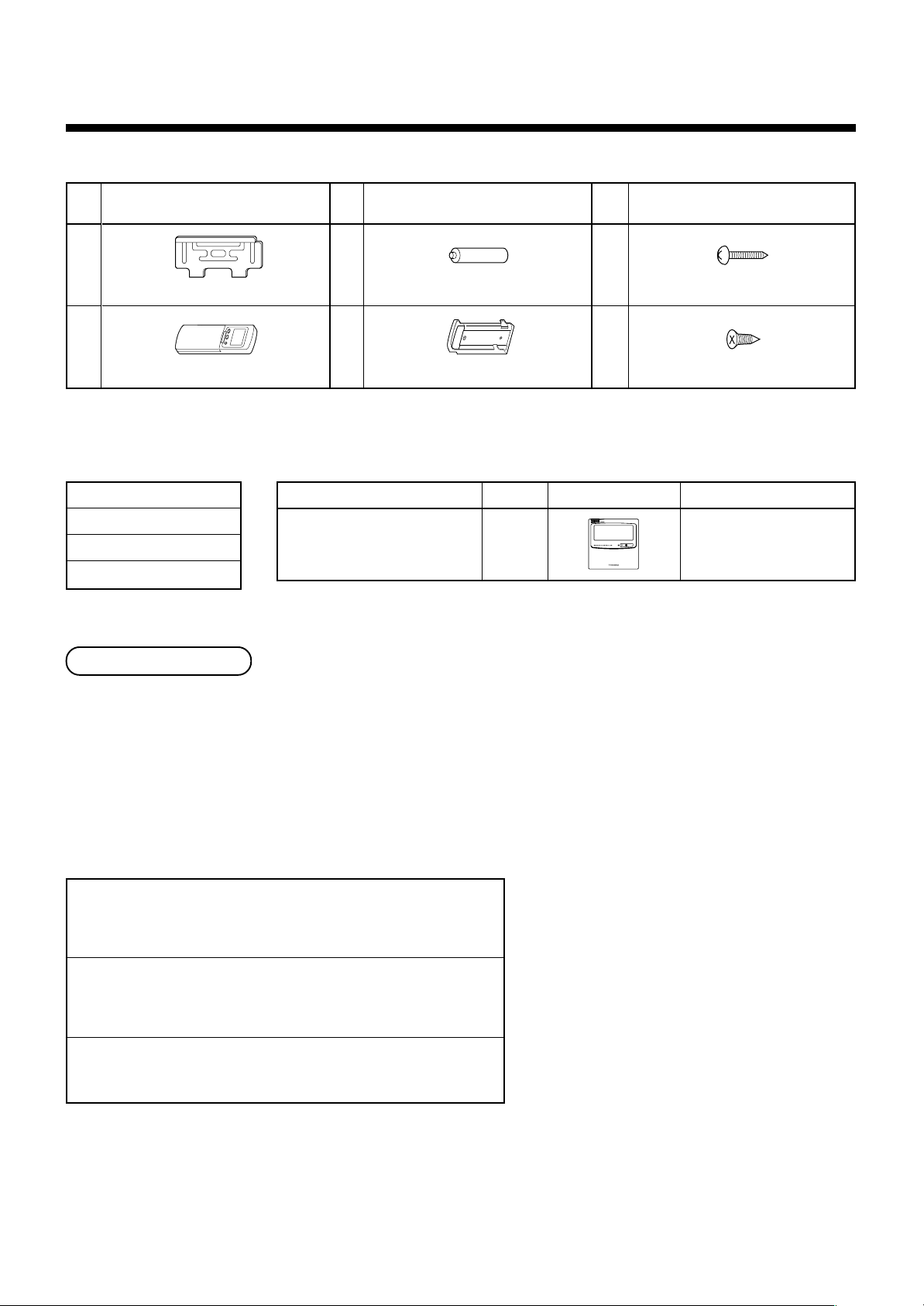
Accessory parts and parts to be procured locally
H Accessory parts
Part
No.
1
Installation plate × 1
2
Wireless remote controller × 1
<Others>
Name
Owner’ s manual
Installation manual
Paper pattern
Part name (Q'ty)
Part
No.
3
Battery × 2
4
Remote controller holder × 1
Part name (Q'ty)
<Separate sold parts>
Part name
Standard wired remote controller
Q’ty
1
Part
No.
5
Mounting screw Ø4 × 25 l x 6
6
Pan head wood screw Ø3.1 × 16 l × 2
Shape Usage
Part name (Q'ty)
Model : RBC-AMT21E
Refrigerant piping
• Piping material used for the conventional refrigerant cannot be used.
• Use copper pipe with 0.8 mm or more thickness for Ø6.4, Ø9.5.
• Flare nut and flare works are also different from those of the conventional refrigerant. Take out the flare nut
attached to the indoor unit of the air conditioner, and use it.
H Parts to be procured locally
Connecting pipe (Liquid side)
(6.4mm (diam.), Nominal (diam.) 1/4” thick 0.8mm)
MMK-AP0072H to MMK-AP0122H
Connecting pipe (Gas side)
(9.5mm (diam.), Nominal (diam.) 3/8” thick 0.8mm)
MMK-AP0072H to MMK-AP0122H
Power supply cord
Cable 3-core 2.5mm
2
, in conformity with Design 60245 IEC57
1
Page 5
1
PRECAUTIONS FOR SAFETY
• Ensure that all Local, National and International regulations are satisfied.
• Read this “PRECAUTIONS FOR SAFETY” carefully before Installation.
• The precautions described below include the important items regarding safety. Observe them without fail.
• After the installation work, perform a trial operation to check for any problem.
Follow the Owner’s Manual to explain how to use and maintain the unit to the customer.
• Turn off the main power supply switch (or breaker) before the unit maintenance.
• Ask the customer to keep the Installation Manual together with the Owner’s Manual.
CAUTION New Refrigerant Air Conditioner Installation
• THIS AIR CONDITIONER ADOPTS THE NEW HFC REFRIGERANT (R410A) WHICH DOES NOT
DESTROY OZONE LAYER.
The characteristics of R410A refrigerant are ; easy to absorb water, oxidizing membrane or oil, and its pressure is
approx. 1.6 times higher than that of refrigerant R22. Accompanied with the new refrigerant, refrigerating oil has also
been changed. Therefore, during installation work, be sure that water, dust, former refrigerant, or refrigerating oil
does not enter the refrigerating cycle.
To prevent charging an incorrect refrigerant and refrigerating oil, the sizes of connecting sections of charging port of
the main unit and installation tools are charged from those for the conventional refrigerant.
Accordingly the exclusive tools are required for the new refrigerant (R410A).
For connecting pipes, use new and clean piping designed for R410A, and please care so that water or dust does
not enter. Moreover, do not use the existing piping because there are problems with pressure-resistance force and
impurity in it.
ENGLISH
CAUTION To Disconnect the Appliance from Main Power Supply
This appliance must be connected to the main power supply by means of a switch with a contact separation of at
least 3 mm.
WARNING
• Ask an authorized dealer or qualified installation professional to install/maintain the air conditioner.
Inappropriate installation may result in water leakage, electric shock or fire.
• Turn off the main power supply switch or breaker before attempting any electrical work.
Make sure all power switches are off. Failure to do so may cause electric shock.
• Connect the connecting wire correctly.
If the connecting wire is connected in a wrong way, electric parts may be damaged.
• When moving the air conditioner for the installation into another place, be very careful not to
enter any gaseous matter other than the specified refrigerant into the refrigeration cycle.
If air or any other gas is mixed in the refrigerant, the gas pressure in the refrigeration cycle becomes abnormally
high and it as a result causes pipe burst and injuries on persons.
• Do not modify this unit by removing any of the safety guards or by by-passing any of the safety
interlock switches.
• Exposure of unit to water or other moisture before installation may cause a short-circuit of
electrical parts.
Do not store it in a wet basement or expose to rain or water.
• After unpacking the unit, examine it carefully if there are possible damage.
• Do not install in a place that might increase the vibration of the unit.
• To avoid personal injury (with sharp edges), be careful when handling parts.
• Perform installation work properly according to the Installation Manual.
Inappropriate installation may result in water leakage, electric shock or fire.
• When the air conditioner is installed in a small room, provide appropriate measures to ensure that
the concentration of refrigerant leakage occur in the room does not exceed the critical level.
2
Page 6
1
PRECAUTIONS FOR SAFETY
• Install the air conditioner securely in a location where the base can sustain the weight adequately.
• Perform the specified installation work to guard against an earthquake.
If the air conditioner is not installed appropriately, accidents may occur due to the falling unit.
• If refrigerant gas has leaked during the installation work, ventilate the room immediately.
If the leaked refrigerant gas comes in contact with fire, noxious gas may generate.
• After the installation work, confirm that refrigerant gas does not leak.
If refrigerant gas leaks into the room and flows near a fire source, such as a cooking range, noxious gas might
generate.
• Electrical work must be performed by a qualified electrician in accordance with the Installation
Manual. Make sure the air conditioner uses an exclusive power supply.
An insufficient power supply capacity or inappropriate installation may cause fire.
• Use the specified wires for wiring connect the terminals securely fix. To prevent external forces
applied to the terminals from affecting the terminals.
• Conform to the regulations of the local electric company when wiring the power supply.
Inappropriate grounding may cause electric shock.
• Do not install the air conditioner in a location subject to a risk of exposure to a combustible gas.
If a combustible gas leaks, and stays around the unit, a fire may occur.
2
SELECTION OF INSTALLATION PLACE
WARNING
• Install the air conditioner where there is sufficient strength to weight of the unit.
If strength is insufficient, the unit may fall down resulting in human injury.
• Perform a specified installation work to guard against an earthquake.
An incomplete installation can cause accidents by the units failing and dropping.
CAUTION
• Do not install the air conditioner in a location subject to a risk of exposure to combustible gas.
Should the combustible gas leak and collect near the unit, fire may occur.
Upon approval of the customer, install the air conditioner in a place that satisfies the following
conditions.
• Place where the unit can be installed horizontally.
• Place where a sufficient servicing space can be ensured for safe maintenance and check.
• Place where drained water will not cause any problem.
Avoid installing in the following places.
• Place exposed to air with high salt content (seaside area), or place exposed to large quantities of sulfide gas
(hot spring). (Should the unit be used in these places, special protective measures are needed.)
• Place exposed to oil, vapor, oil smoke or corrosive gas.
• Place where organic solvent is used nearby.
• Place close to a machine generating high frequency.
• Place near door or window where may come to contact with the outside air of high humidity. (Dewing may be caused.)
• Place where special spray is frequently used.
• Place with poor ventilation.
3
Page 7
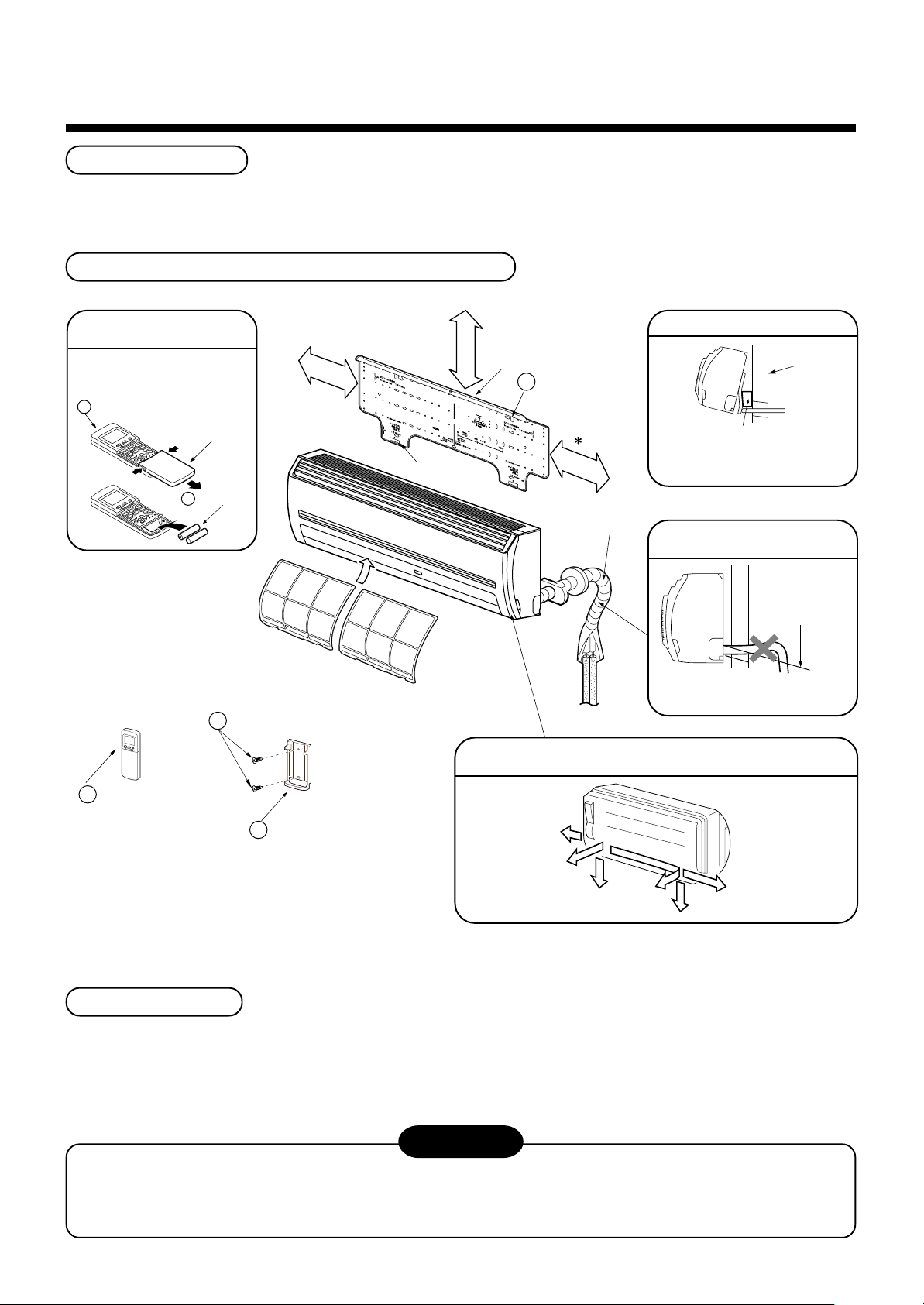
Installation space
Reserve space required to install the indoor unit and for service work.
Keep 100mm or more for clearance between top plate of the indoor unit and the ceiling surface.
Installation diagram of Indoor and outdoor units
Before installing the
wireless remote controller
• With the remote controller cover
open, load the batteries supplied
correctly, observeing their polarity.
2 W ireless remote controller
Cover
3 Batteries
6
Pan head wood screw
170mm
or more
Air filter
(Attach to the front panel)
Hook
For the rear left and left piping
Hook
100 mm or more
1
Installation
plate
Wall
Insert the cushion between the
170mm
or more
Shield pipe
indoor unit and wall, and tilt the
indoor unit for better operation.
Do not allow the drain hose to
get slack
Cut the piping hole
sloped slightly
Make sure to run the drain hose
sloped downward.
The auxiliary piping can be connected the left, rear left, rear right,
right, bottom right or bottom left.
2
Wireless
remote controller
4
Remote control holder
Right
Rear right
Bottom right
Rear left
∗ When installing the Flow Selector Unit (FS Unit),
keep a space more than 300mm for wiring work.
Installation place
• A place which provides the spaces around the indoor unit as shown in the above diagram.
• A place where there is no obstacle near the air inlet and outlet.
• A place that allows easy installation of the piping to the outdoor unit.
• A place which allows the front panel to be opened.
CAUTION
• Direct sunlight to the indoor unit’ s wireless receiver should be avoided.
• The microprocessor in the indoor unit should not be too close to RF noise sources.
(For details, see the owner’ s manual.)
Left
Bottom left
4
Page 8
2
SELECTION OF INSTALLATION PLACE
Remote controller
• A place where there are no obstacles such as a curtain that may block the signal from the indoor unit.
• Do not install the remote controller in a place exposed to direct sunlight or close to a heating source, such as a
stove.
• Keep the remote controller at least 1m apart from the nearest TV set or stereo equipment.
(This is necessary to prevent image distur-bances or noise interference.)
• The location of the remote controller should be determined as shown below.
(Top view)
Indoor unit
Reception range
Remote controller
* : Axial distance
5 m
45
˚
45˚
5
m
Remote controller
3
(Side view)
7 m
Indoor unit
75˚
Reception
range
INSTALLATION OF INDOOR UNIT
WARNING
Install the air conditioner certainly to sufficiently withstand the weight.
If the strength is insufficient, the unit may fall down resulting in human injury.
Perform a specified installation work to guard against strong wind or earthquake.
An incomplete installation can cause accidents by the units falling and dropping.
REQUIREMENT
* 7 m
Strictly comply with the following rules to prevent damage of the indoor units and human injury.
• Do not put a heavy article on the indoor unit. (Even units are packaged)
• Carry in the indoor unit as it is packaged if possible. If carrying in the indoor unit unpacked by necessity, be
sure to use buffering cloth, etc. to not damage the unit.
• To move the indoor unit, do not apply force to the refrigerant pipe, drain pan, foamed parts, or resin parts, etc.
• Carry the package by two or more persons, and do not bundle it with PP band at positions other than specified.
Be careful to the following items when installing the unit.
• Considering air discharge direction, select an
installation place where discharge air can circulate
evenly in a room. Avoid to install the unit at place with
“NO GOOD” mark in the right figure.
OK NO GOOD
Bad installation place
Good installation place
Cooled well all over.
: Not cooled well.
Screen
5
Page 9
4
Projection
15mm or less
7
Mounting screw
Ø4 × 25
Clip anchor
(local parts)
5mm dia. hole
Anchor bolt
NO
GOOD
NO
GOOD
OK
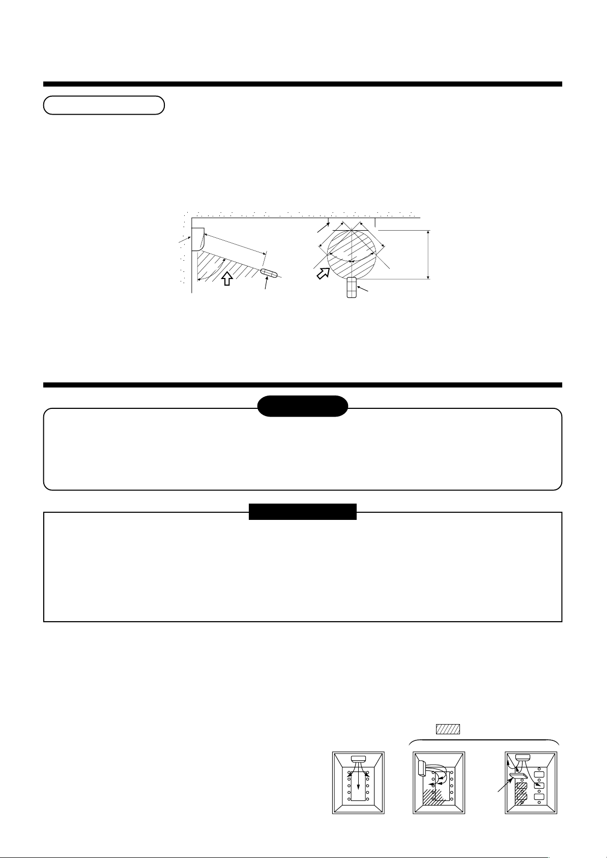
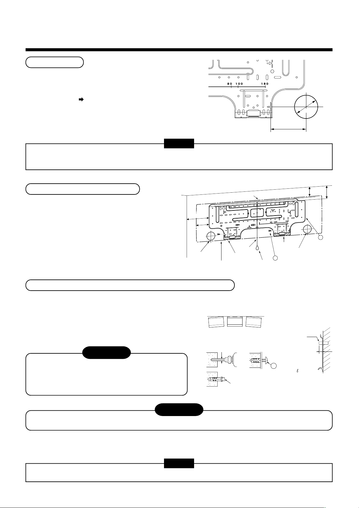
CUTTING A HOLE AND MOUNTING INSTALLATION PLATE
Cutting a hole
In case of installing the refrigerant pipes from the rear:
1. Decide the hole position for piping at 100mm from
the arrow mark ( ) on the installation plate and
drill a hole with Ø65mm at a slight downward slant
toward outdoor side.
The center of the pipe
hole is above the arrow.
100 mm
Pipe
hole
65 mm
NOTE
• When drilling a wall that contains a metal lath, wire lath or metal plate, be sure to use a pipe hole brim ring sold
separately.
Mounting the installation plate
For installation of the indoor unit,
use the paper pattern in the accessory parts.
170
85
Pipe hole
Indoor unit
When the installation plate is directly mounted on the wall
1. Securely fit the installation plate onto the wall by screwing
it in the upper and lower parts to hook up the indoor unit.
2. To mount the installation plate on a concrete wall with
anchor bolts, utilize the anchor bolt holes as illustrated in
the above figure.
3. Install the installation plate horizontally in the wall.
CAUTION
Hook
Hook
Thread
Weight
Hook
Pipe hole
Mounting screw
5
107
Installation
plate
127.5
1
When installing the installation plate with a mounting
screw, do not use the anchor bolt hole.
Otherwise the unit may fall down and result in personal
injury and property damage.
CAUTION
Failure to firmly install the unit may result in personal injury and property damage if the unit falls.
• In case of block, brick, concrete or similar type walls, make 5mm dia. holes in the wall.
• Insert clip anchors for appropriate mounting screws.
NOTE
• Secure four corners and lower parts of the installation plate with 4 to 6 mounting screws to install it.
6
Page 10

5
Heat insulator
Drain hose
Do not apply lubricating oil
(refrigerant machine oil) when
inserting the drain cap.
Application causes deterioration
and drain leakage of the plug.
Insert a hexagon
wrench (4 mm)
No gap
PIPING AND DRAIN HOSE INSTALLATION
Piping and drain hose forming
* Apply thermal-insulation for both refrigerant pipe and drain hose surely so that no dewing generates inside of the
equipment. (Use polyethylene foam for insulating material.)
Rear right
Rear left
Bottom left
Left
Bottom right
Right
Die-cutting
front panel slit
Changing
drain hose
Piping
preparation
1. Die- cutting front panel slit
For piping work at the left side, cut off the left slit for notching of the front panel.
(A knife will produce flaws on the panel, so use nippers.)
2. Changing drain hose
For piping work at the left side, lower left side, and left back side, it is necessary to change the drain hose and
drain cap.
How to remove the drains cap
Clip drain cap by needle- nose pliers, and pull out.
How to install the drain hose
Firmly insert drain hose connecting part until hitting on
a heat insulator.
How to fix the drains cap
1) Insert hexagonal wrench (Ø4mm) in a center
head.
4 mm
2) Firmly insert drains cap.
CAUTION
Firmly insert the drain hose and drain cap; otherwise, water may leak.
7
Page 11

In case of right or left piping
270mm
170mm
43 mm
(To the fore front of flare)
Liquid side
Gas side
Outward form of indoor unit
R 30 mm (Use polish polyethylene
core or the like for bending pipe.)
Use the handle of screwdriver, etc.
80˚
• After scribing slits of the front panel with a knife or a
marking-off pin, cut them with a pair of nippers or an
equivalent tool.
In case of bottom right or bottom left piping
• After scribing slits of the front panel with a knife or a
marking- off pin, cut them with a pair of nippers or an
equivalent tool.
Left- hand connection with piping
Bend the connecting pipe so that it is laid within 43mm above
the wall surface. If the connecting pipe is laid exceeding
43mm above the wall surface, the indoor unit may unstably
be set on the wall. When bending the connecting pipe, make
sure to use a spring bender so as not to crush the pipe.
Bend the connection pipe within a radius of 30 mm.
To connect the pipe after installation of the unit (figure)
Slit
Slit
If the pipe is bent incorrectly, the indoor unit may unstably be set on the wall.
After passing the connecting pipe through the pipe hole, connect the connecting pipe to the auxiliary pipes and
wrap the facing tape around them.
• Bind the auxiliary pipes (two) and connecting cable with facing tape tightly. In case of leftward piping and rear-
leftward piping, bind the auxiliary pipes ( two) only with facing tape.
• Carefully arrange pipes so that any pipe does not stick out of the rear plate of the indoor unit.
• Carefully connect the auxiliary pipes and connecting pipes to each other and cut off the insulating tape wound
on the connecting pipe to avoid double- taping at the joint, moreover, seal the joint with the vinyl tape, etc.
• Since dewing results in a machine trouble, make sure to insulate both the connecting pipes.
• When bending a pipe, carefully do it, not to crush it.
(Use polyethylene foam as insulating material.)
Auxiliary pipes
Installation plate
NOTE
CAUTION
Indoor unit
Connecting cable
8
Page 12

6
INDOOR UNIT FIXING
1. Pass the pipe through the hole in the wall, and hook the
indoor unit on the installation plate at the upper hooks.
2. Swing the indoor unit to right and left to confirm that it is firmly
hooked up on the installation plate.
3. While pressing the indoor unit onto the wall, hook it at the
lower part on the installation plate. Pull the indoor unit toward
you to confirm that it is firmly hooked up on the installation
plate.
• For detaching the indoor unit from the installation plate, pull the
indoor unit toward you while pushing its bottom up at the
specified parts.
Hook
1
2
Hook here
1
Installation plate
Press
(unhook)
PushPush
7
1. Run the drain hose sloped downwards.
DRAINAGE
NOTE
• Hole should be made at a slight downward
slant on the outdoor side.
2. Put water in the drain pan and make sure that
the water is drained out of doors.
3. When connecting extension drain hose,
insulate the connecting part of extension
drain hose with shield pipe.
CAUTION
Arrange the drain pipe for proper drainage from the unit.
Improper drainage can result in dew- dropping.
Do not rise the drain hose.
50 mm
or more
Do not put the
drain hose end
into water.
Shield pipe
Drain hose
Inside the
room
Do not form the drain hose
into a wavy shape.
Do not put the
drain hose end in
the drainage ditch.
Extension drain hose
Wall
Drain
guide
This air conditioner has the structure designed to drain water collected
from dew, which forms on the back of the indoor unit, to the drain pan.
Therefore, do not store the power cord and other parts at a height
above the drain guide.
9
Space for pipes
Page 13

8
REFRIGERANT PIPING
WARNING
• If refrigerant gas has leaked during the installation work, ventilate the room immediately.
• If the leaked refrigerant gas comes in contact with fire, noxious gas may generate.
• After the installation work, confirm that refrigerant gas does not leak.
• If refrigerant gas leaks into the room and flows near a fire source, such as a cooking range, noxious gas may
generate.
REQUIREMENT
When the refrigerant pipe is long, set the support brackets to fix the pipe with 2.5 to 3m intervals. If the pipe is
not fixed, abnormal sound may generate.
Be sure to use the flare nuts attached to the indoor unit or those for R410A.
Permissible pipe length and permissible height difference
They are different according to the used outdoor unit. For details, refer to the Installation Manual attached to the
outdoor unit.
Piping material and dimensions
Piping material
Model
Pipe size (mm)
• Use a clean and new pipe, and check that impurity such as dust, oil, moisture, etc. does not adhere in the pipe.
Gas side
Liquid side
Pipe Forming/End Positioning
Phosphor deoxidization joint-less pipe for air conditioner
MMK-AP0072H to MMK-AP0122H
Ø9.5
Ø6.4
• Flaring diam. meter size :
A
A (Unit : mm)
Flaring
1. Cut the pipe with a pipe cutter.
OK NO GOOD
90˚
Obliquity Roughness Warp
Outer diam. of copper pipe
6.4
9.5
12.7
+0
A
- 0.4
R410A
9.1
13.2
16.6
2. Insert a flare nut into the pipe, and flare the pipe.
As the flaring sizes of R410A differ from those of
refrigerant R22, the flare tools newly manufactured
for R410A are recommended.
However, the conventional tools can be used by
adjusting projection margin of the copper pipe.
15.9
In case of flaring for R410A with the conventional
*
flare tool, pull it out approx. 0.5 mm more than that
for R22 to adjust to the specified flare size.
The copper pipe gauge is useful for adjusting
projection margin size.
10
19.7
Page 14

8
REFRIGERANT PIPING
• Projection margin in flaring :
B (Unit : mm)
Rigid (Clutch type)
Outer diam. of
copper pipe
6.4
9.5
12.7
15.9
Imperial (Wing nut type)
Outer diam. of copper pipe
R410A tool used
R410A R22
0 to 0.5 (Same as left)
0 to 0.5 (Same as left)
0 to 0.5 (Same as left)
0 to 0.5 (Same as left)
6.4
9.5
12.7
15.9
R410A R22
1.5 to 2.0 1.0 to 1.5
1.5 to 2.0 1.0 to 1.5
2.0 to 2.5 1.5 to 2.0
2.0 to 2.5 1.5 to 2.0
Conventional tool used
R410A R22
1.0 to 1.5 0.5 to 1.0
1.0 to 1.5 0.5 to 1.0
1.0 to 1.5 0.5 to 1.0
1.0 to 1.5 0.5 to 1.0
B
Airtight test/Air purge, etc.
For airtight test, air purge, addition of refrigerant, and
gas leak check, follow the Installation Manual attached
to the outdoor unit.
Open fully valves of the outdoor unit
Gas leak check
Check with a leak detector or soap water whether gas
leaks or not, from the pipe connecting section or cap
of the valve.
REQUIREMENT
Use a leak detector manufactured exclusively for
HFC refrigerant (R410A, R134a, etc.).
Connection of refrigerant pipe
Connect all the refrigerant pipes with flare connecting
work.
• Since the atmospheric pressure only is sealed as the
sealing gas, it is not abnormal that “Pushu…” sound
is not heard when the flare nut is removed.
• Be sure to use a double spanner for pipe connecting
work of the indoor unit.
Work using double spanner
• Refer to the following table for tightening torque.
Connecting pipe
outer dia. (mm)
Ø6.4
Tightening torque
(N•m)
14 to 18
(1.4 to 1.8 kgf•m)
Re-tightening
torque (N•m)
18
(1.8 kgf•m)
Ø9.5
Ø12.7
Ø15.9
33 to 42
(3.3 to 4.2 kgf•m)
50 to 62
(5.0 to 6.2 kgf•m)
68 to 82
(6.8 to 8.2 kgf•m)
42
(4.2 kgf•m)
50
(5.0 kgf•m)
68
(6.8 kgf•m)
11
Page 15

9
ELECTRIC WORK
WARNING
1. Using the specified wires, ensure to connect the wires, and fix wires securely so that the
external strength of the wires do not transmit to the connecting part of the terminals.
Incomplete connection or fixation may cause a fire, etc.
2. Be sure to connect earth wire. (Grounding work)
Do not connect the earth wire to gas pipe, city water pipe, lightning rod, or the earth wire of telephone.
Incomplete grounding causes an electric shock.
3. For electric work, strictly follow to the Local Regulation in each country and the Installation
Manual, and use an exclusive circuit.
Capacity shortage of power circuit or incomplete installation may cause an electric shock or a fire.
CAUTION
Be sure to install an earth leakage breaker.
If an earth leakage breaker is not installed, an electric shock may be caused.
REQUIREMENT
• For power supply wiring, strictly conform to the Local Regulation in each country.
• For wiring of power supply of the outdoor units, follow to the Installation Manual of each outdoor unit.
• Never connect 220–240V power to the terminal blocks (A, B, U1, U2, X, Y, etc.) for control wiring.
(Otherwise, the system will be failed.)
• Perform the electric wiring so that it does not come to contact with the high-temperature part of the pipe.
The coating may melt resulted in an accident.
• After connecting wires to the terminal blocks, provide a trap and fix wires with the wire clamp.
• Store the refrigerant piping line and control wiring line in the same line.
• Do not turn on the power of the indoor unit until vacuuming of the refrigerant pipes completes.
Power supply specifications
Cables and remote controller wires are procured locally.
For the power supply specifications, follow to the table below. If capacity is little, it is dangerous because overheat or
seizure may be caused.
For specifications of the power capacity of the outdoor unit and the power supply cables, refer to the Installation
Manual attached to the outdoor unit.
220–240V ~ 50Hz
220V
Twist wire : 2.0 mm²
Twist wire : 2.5 mm²
Twist wire : 0.5 to 2.0 mm²
~ 60Hz
2
2
2
Indoor unit power supply (*1)
Communication line
Power supply
Power supply switch/Earth leakage breaker or power supply wiring/fuse rating for
indoor units should be selected by the accummulated total current values of the indoor units.
Power supply wiring
Indoor/Outdoor inter-unit wiring (*2)
Central control line wiring (*3)
Remote controller wiring (*4)
20m or less
50m or less
Q’ty
Wire size
Q’ty
Wire size
Q’ty
Wire size
(Up to 1000m) Twist wire : 1.25 mm²
(Up to 2000m) Twist wire : 2.00 mm²
(Up to 1000m) Twist wire : 1.25 mm²
(Up to 2000m) Twist wire : 2.00 mm²
12
Page 16

9
3
1
2
Air inlet grille
Front panel
ELECTRIC WORK
Indoor unit power supply (*1)
• For the power supply of the indoor unit, prepare the exclusive power supply separated from that of the outdoor unit.
• Arrange the power supply, earth leakage breaker, and main switch of the indoor unit connected to the same
outdoor unit so that they are commonly used.
• Power supply cord specification : Cable 3-core 2.5mm², in conformity with Design 60245 IEC 57.
Indoor/Outdoor inter-unit wiring, Central controller wiring (*2) (*3)
• 2-core with polarity wires are used for the Indoor/Outdoor inter-unit wiring and Central controller wiring.
• To prevent noise trouble, use 2-core shield wire.
• The length of the communication line means the total length of the inter-unit wire length between indoor and
outdoor units added with the central control system wire length.
Remote controller wiring (*4)
• 2-core with non-polarity wire is used for wiring of the remote controller wiring and group remote controllers wiring.
Remote controller wiring, remote
controller inter-unit wiring
Total wire length of remote controller
wiring and remote controller inter-unit
wiring = L + L1 + L2 + … Ln
Total wire length of remote controller inter-unit wiring = L1 + L2 + … Ln
Indoor unit
Remote
controller
wiring
Remote
controller
Twist wire: 0.5mm2 to 2.0mm2 × 2
In case of wired type only
In case of wireless type included
Indoor unit
L1 L2 Ln
Remote controller inter-unit wiring
Up to 500m
Up to 400m
Up to 200m
Indoor unit Indoor unit
(Max. 8 units)
The remote controller wire
(Communication line) and
AC220–240V wires cannot be
parallel to contact each other and
cannot be stored in the same
conduits. If doing so, a trouble
may be caused on the control
system due to noise, etc.
Wiring connection
How to connect the power cable
For the air conditioner that does not have power cable, connect a power cable to it as mentioned below.
1. Open the air inlet grille upward.
2. Remove the four screws securing the front panel.
3. Slightly open the lower part of the front panel then pull the upper part of the front panel toward you to remove it
from the rear plate.
4. After removing the front panel, remove the power cable connect cover and the cord clamp.
5. Connect and secure the power supply cable and secure the cord clamp and the power connect cover.
6. Cut the slit and front panel, and put the power supply cable through the notch.
7. Be sure to smooth the notch with a file, etc.
CAUTION
REQUIREMENT
• Be sure to pass the cable through the cable
connection port of the indoor unit.
• The low-voltage circuit is provided for the remote
controller.
13
Page 17

• Tighten the screws of the terminal block, and fix the cables with cord
clamp attached to the electric parts box.
(Do not apply tension to the connecting section of the terminal block.)
U1NLU2AB
U1NLU2 A B
Cord clamp
R(L) S(N)
>
ABS
<
Cord clamp
Remote
controller cable
Power supply
cable
40mm
10mm
10mm
NL
110mm
Screw
Connector cover
Terminal block
Notch
Wiring connection for flow selector unit
How to connect the wiring of flow selector unit
For the flow selector unit that have power supply cord, connect a power supply cable to it as mentioned below.
1. Open the air inlet grille upward.
2. Remove the four screws securing the front panel.
3. Slightly open the lower part of the front panel then pull the upper part of the front panel toward you to remove it
from the rear plate.
4. After removing the front panel, remove the wiring cover and the cord clamp.
5. Connect and secure the power supply cable of flow selector unit and secure the cord clamp.
6. The control wires are included in terminal block part of the power supply.
Take out the control wires outwards through the slit of the terminal block.
7. Fasten the wiring cover surely with screws.
8. Connect the control wire taken out through the slit on the terminal block and the control wire from the flow
selector unit at the relay terminal section.
Control wire
Terminal
block
Control wire from
the flow selector
14
Slit of the
terminal block
Earth line
Terminal
block
Power supply cable
for flow selector unit
Wiring cover
Cord clamp
Screw
Screw
Screw
Page 18

Wire from remote
controller or sensor
Remote controller wiring
Wire joint
9
ELECTRIC WORK
Remote controller wiring
• Strip off approx. 14mm cover of the wire to be connected.
• Twist wire of the remote controller to be connected with wire of the remote controller unit (or sensor), and press-fit
them with a wire joint. (Wire joints (White: 2 pieces) are included in the accessory of the main remote controller
(sold separately) or wireless remote controller kit (sold separately).)
• As the remote controller wire has no polarity, there is no problem if connections to indoor unit terminal blocks A
and B are reversed.
<Wiring diagram>
Terminal block
for remote controller
wiring of indoor unit
A
B
Approx. 200mm
W
B
W : White
B : Black
Remote
controller unit
or sensor part
Remote controller wire
(Local procure)
Connecting
part
Wire from remote controller unit
or sensor
Wiring between indoor and outdoor units
Header unit Follower unit
Earth leakage breaker
Outdoor power supply
3-phase
380–415V, 50Hz
380V, 60Hz
Central control line wire
(Open)
Power supply
220–240V
220V
Indoor power supply
220–240V
220V ~ 60Hz
~
50Hz
~
50Hz
~
60Hz
Remote controller,
for central control, etc.
Earth leakage breaker
Switch
Indoor/Outdoor inter-unit wire
(Earth)
Connection of shield
wire closed terminal
Connection of shield
wire closed terminal
NOTE
An outdoor unit connected
with indoor/outdoor inter-unit
wire becomes automatically
the header unit.
Earth
Inter-unit wire between outdoor units
Pull box
(Earth)
Address setup
Set up the addresses according to the Installation Manual attached to the outdoor unit.
15
Indoor unit
(Remote controller group operation)
Page 19

10
APPLICABLE CONTROLS
NOTIFICATION
When using the equipment at the first time, it will take a lot of time that the remote controller accepts an
operation after power was on. However, it is not a trouble.
• Automatic address
• While automatic addressing, the operation cannot be performed on the remote controller.
• For automatic addressing, Max. 10 minutes (generally, approx. 5 minutes) are required.
• When power will be turned on after finish of automatic addressing;
• It will require Max. 10 minutes (generally, approx. 3 minutes) that outdoor unit starts operation after power was on.
As all have been set to [Standard] at the shipment, change the setup of the indoor unit if necessary.
To change the setup, use the main remote controller (wired remote controller).
The wireless remote controller is unavailable for address setting.
* The setup change for wireless remote controller, sub remote controller, or remote controller-less system
(Central control remote controller only is provided.) is impossible. In these cases, prepare and mount a
separate main remote controller.
Exchange of applicable control setup
Basic operation procedure for setup exchange
Change the setup while operation of the equipment stops.
(Be sure to stop the operation of a set.)
Procedure
SET
, CL, and buttons simultaneously for 4 seconds or more, after a while, the display part
UNIT
button, the indoor unit No. in the group control is displayed successively. Select an
1
2
3
When pushing
flashes as shown in the figure.
Check that the displayed item code is [10].
• If the item code indicates other than [10], push
the display, and then retry the operation from the first step.
(For some time after button has been pushed, the operation of
the remote controller cannot be accepted.)
(In a group control, the firstly displayed
indoor unit No. becomes the header unit.)
Every pushing
indoor unit of which setup to be changed.
In this time, the position of the indoor unit of which setup to be
changed can be confirmed because the fan and the flap of the
selected indoor unit work.
Using , buttons of set temperature, specify the item
code [**].
Using , buttons of timer time, select set data [
4
CODE No.
UNIT No.
R.C. No.
4
6
1
UNIT
CL
SET
2
3
5
Description
button to erase
(* The display changes according to the indoor unit model.)
].
****
*
** **
UNIT No.
R.C. No.
UNIT No.
** **
R.C. No.
CODE No.
CODE No.
**
5
6
SET
Push
• To change the setup of an indoor unit other than the selected one, start operation from Procedure
• To change the setup of another setup in the selected indoor unit, start operation from Procedure
Pushing
When the setup finished, push button. (The setup is determined.)
Pushing
normal stop status.
(For some time after button has been pushed, the operation of
the remote controller cannot be accepted.)
button. In this time, if the display changes from flashing to lighting, the setup completes.
CL
button clears the set up contents which have been already set. In this case, retry from Procedure 2.
button deletes the display and returns the status to
16
2
.
3
.
Page 20

10
APPLICABLE CONTROLS
Change of lighting time of filter sign
According to the installation condition, the lighting time
of the filter sign (Notification of filter cleaning) can be
changed.
Follow to the basic operation procedure
(1 → 2 → 3 → 4 → 5 → 6 ).
• For the item code in Procedure 3 , specify [01].
• For the [Set data] in Procedure 4 , select the setup
data of filter sign lighting time from the following
table.
Setup data
0000
0001
0002
0003
0004
Filter sign lighting time
None
150H (At shipment from factory)
2500H
5000H
10000H
To secure better effect of heating
When it is difficult to obtain satisfactory heating due to
installation place of the indoor unit or structure of the
room, the detection temperature of heating can be
raised. Also use a circulator, etc. to circulate heat air
near the ceiling.
Follow to the basic operation procedure
(1 → 2 → 3 → 4 → 5 → 6 ).
• For the item code in Procedure 3 , specify [06].
• For the set data in Procedure 4 , select the setup
data of shift value of detection temperature to be set
up from the table below.
Adjustment of air direction
1. Using the remote controller switch, change the up/
down air direction by moving the horizontal flap.
2. Adjust the right/left air direction by bending the
vertical grille inside of the air outlet port with hands.
REQUIREMENT
Do not touch the horizontal flap directly with
hands; otherwise a trouble may be caused.
For handling of the horizontal flap, refer to
“Owner’s Manual” attached to the outdoor unit.
Group control
In a group control, a remote controller can control up
to maximum 8 units.
• The wired remote controller only can control a group
control. The wireless remote controller is unavailable
for this control.
• For cabling procedure and cables of the individual
line (Identical refrigerant line) system, refer to
“Electric work” in this Manual.
• Cabling between indoor units in a group is performed
in the following procedure.
Connect the indoor units by connecting the remote
controller inter-unit cables from the remote controller
terminal blocks (A, B) of the indoor unit connected
with a remote controller to the remote controller
terminal blocks (A, B) of the other indoor unit.
(No polarity)
• For address setup, refer to the Installation Manual
attached to the outdoor unit.
Setup data
0000
0001
0002
0003
0004
0005
0006
Detection temp shift value
No shift
+1°C
+2°C (At shipment from factory)
+3°C
+4°C
+5°C
+6°C
NOTE
Net work adapter (Model TCB-PCNT20E) can not
connect to this High Wall type air conditioner.
17
Page 21

11
TEST RUN
Before test operation
• Before turning on the power supply, carry out the following items.
1) Using 500V-megger, check there is 1MΩ or more between the
terminal block of the power supply and the earth. If 1MΩ or less
is detected, do not run the unit.
2) Check that all the valves of the outdoor unit are fully opened.
• Never push the electromagnetic contactor to carry out a forced test operation.
(It is very dangerous because a protective device does not work.)
How to execute test operation
• Using the remote controller, check the operation in the usual operation. For the operation procedure, refer to the
attached Owner’s Manual.
A forced test operation can be executed in the following procedure under condition of thermo-OFF of room
temperature.
In order to prevent a serial operation, the forced test operation is released after 60 minutes and returns to the
usual operation.
NOTE
Do not use a forced operation in cases other
than test operation because it applies an
excessive load to the air conditioner.
To protect the compressor at
starting time, keep power-ON
condition before 12 hours or more.
1, 5
In case of wired remote controller
SET
WARNING
2, 4
UNIT
CL
3
Procedure
1
2
3
4
5
Description
Keep button pushed for 4 seconds or more. [TEST] is displayed
on the display part and the selection of mode in the test mode is
permitted.
Push button.
Using button, select the operation mode, [COOL] or [HEAT].
• Do not run the air conditioner in a mode other than [COOL] or [HEAT].
• The temperature controlling function does not work during test
operation.
• The detection of error is performed as usual.
After the test operation, push button to stop the operation.
1
(Display part is same as procedure
Push button to cancel (release from) the test operation mode.
([TEST] disappears on the display part and the status returns to a
normal stop status.)
)
TEST
18
Page 22

11
TEST RUN
In case of wireless remote controller (Forced test operation is performed in a different way. )
REQUIREMENT
1. For the operation procedure, be sure to follow the Owner’s Manual.
2. Finish the forced cooling operation in a short time because it applies excessive strength to the air conditioner.
3. A test operation of forced heating is unavailable. Perform a test operation by heating operation using the
switches of the remote controller.
However heating operation may be not carried out according to the temperature conditions.
• Check wiring/piping of indoor and outdoor units
1. Open the front panel.
2. When pushing “TEMPORARY” button for 10 seconds or more, “Pi!” sound is heard and the operation changes
to a forced cooling operation. After approx. 3 minutes, a cooling operation starts forcedly.
Check cool air starts blowing. If the operation does not start, check wiring again.
3. To stop a test operation, push “TEMPORARY” button once again (Approx. 1 second).
The up/down air flow adjusting plate closes and the operation stops.
• Check transmission of remote controller
1. Push “START/STOP” button of the remote controller to check an operation can also start by the remote
controller.
• When pushing “TEMPORARY” button once (For 1 second), the operation changes to automatic operation.
For a forced cooling operation, keep the “TEMPORARY” button pushed over 10 seconds.
•“Cooling” operation by the remote controller may be unavailable according to the temperature conditions.
Check wiring/piping of the indoor and outdoor units in forced cooling operation.
TEMPORARY button
TEMPORARY button
19
Page 23

12
TROUBLESHOOTING
Confirmation and check
When a trouble occurred in the air conditioner, the
check code and the indoor unit No. appear on the
display part of the remote controller.
The check code is only displayed during the operation.
If the display disappears, operate the air conditioner
according to the following “Confirmation of error
history” for confirmation.
Confirmation of error history
When a trouble occurred on the air conditioner, the
error history can be confirmed with the following
procedure.
(The error history is stored in memory up to 4 errors.)
This history can be confirmed from either operating
status or stop status.
3
Check code
UNIT No.
R.C. No.
Indoor unit No. in which
an error occurred
UNIT
CL
SET
1
CODE No.
2
Procedure
1
2
3
Description
When pushing
more, the right display appears.
If [Service Check] is displayed, the mode enters in the error history
mode.
• [01: Order of error history] is displayed in CODE No. window.
• [Check Code] is displayed in CHECK window.
• [Indoor unit address in which an error occurred] is displayed in
UNIT No.
Every pushing , buttons, the error history stored in the memory is displayed in order.
The numbers in CODE No. indicates CODE No. [01] (Latest) → [04] (Oldest).
CAUTION
Do not push
After confirmation, push button to return to the usual display.
SET
and buttons simultaneously for 4 seconds or
button because all the error history of the indoor unit will be deleted.
CL
UNIT No.
R.C. No.
CODE No.
20
Page 24

12
TROUBLESHOOTING
Check method
On the remote controller (Main remote controller, Central control remote controller) and the interface P.C. board of
the outdoor unit (I/F), a check display LCD (Remote controller) or 7-segment display (on the outdoor interface P.C.
board) to display the operation is provided. Therefore the operation status can be known. Using this self-diagnosis
function, a trouble or position with error of the air conditioner can be found as shown in the table below.
Check code list
The following list shows each check code. Find the check contents from the list according to part to be checked.
• In case of check from indoor remote controller: See “Main remote controller display” in the list.
• In case of check from outdoor unit: See “Outdoor 7-segment display” in the list.
• In case of check from indoor unit with wireless remote controller: See “Sensor block display of receiving unit” in the list.
Main
remote
controller
display
E01
E02
E03
E04
E06
—
E08
E09
E10
E12
E15
E16
E18
E19
E20
E23
E25
E26
E28
E31
Terminology
Check code
Outdoor 7-segment display
Auxiliary code
——
——
——
——
No. of indoor units in which
E06
sensor has been normally received
E07 —
E08 Duplicated indoor addresses
——
——
01: Indoor/Outdoor communication
E12 02: Communication between
E15 —
E16
——
E19
E20
E23 —
E25 —
E26
E28 Detected outdoor unit number
E31 04: Fan IPDU error
outdoor units
00: Capacity over
~: No. of connected units
01
00: Header is nothing
02: Two or more header units
01: Outdoor of other line connected
02: Indoor of other line connected
No. of outdoor units which
received signal normally
01: IPDU1 error
02: IPDU2 error
03: IPDU1, 2 error
05: IPDU + Fan IPDU error
06: IPDU2 + Fan IPDU error
07: All IPDU error
AI-NET : Artificial Intelligence.
IPDU : Intelligent Power Drive Unit
¡ : Lighting,
ALT. : Flashing is alternately when there are two flashing LED.
SIM : Simultaneous flashing when there are two flashing LED.
Wireless remote controller
Sensor block display
of receiving unit
Operation
Timer Ready Flash
ll
¤
ll
¤
ll
¤
ll
ll
ll
ll
¤
ll
¤
ll
¤
ll
¤
ll
ll
ll
¤
ll
ll
ll
ll
ll
ll
ll
¤
¤
¤
¤
¤
¤
¤
¤
¤
¤
¤
¤
: Flashing, l : Goes off
¤
Check code name
Communication error between indoor and
remote controller
(Detected at remote controller side)
Remote controller transmission error
Communication error between indoor and
remote controller (Detected at indoor side)
Communication circuit error between indoor/
outdoor (Detected at indoor side)
Decrease of No. of indoor units
Communication circuit error between indoor/
outdoor (Detected at outdoor side)
Duplicated indoor addresses
Duplicated main remote controllers
Communication error between indoor MCU
Automatic address start error
Indoor is nothing during automatic addressing
Capacity over / No. of connected indoor units
Communication error between indoor units
Outdoor header units quantity error
Other line connected during automatic
address
Sending error in communication between
outdoor units
Duplicated follower outdoor addresses
Decrease of No. of connected outdoor units
Follower outdoor unit error
IPDU communication error
Judging device
Remote controller
Remote controller
Indoor
Indoor
I/F
I/F
Indoor / I/F
Remote controller
Indoor
I/F
I/F
I/F
Indoor
I/F
I/F
I/F
I/F
I/F
I/F
I/F
21
Page 25

Main
remote
controller
display
F01
F02
F03
F04
F05
F06
F07
F08
F10
F12
F13
F15
F16
F23
F24
F29
F31
H01
H02
H03
H04
H06
H07
H08
H14
H16
L03
L04
L05
L06
L07
L08
L09
L10
L20
L28
L29
L30
—
Check code
Outdoor 7-segment display
Auxiliary code
——
——
——
F04 —
F05 —
F06 —
F07 —
F08 —
——
F12 —
01: Comp. 1 side
F13
02: Comp. 2 side
F15 —
F16 —
F23 —
F24 —
——
F31 —
01: Comp. 1 side
H01
02: Comp. 2 side
01: Comp. 1 side
H02
02: Comp. 2 side
01: Comp. 1 side
H03
02: Comp. 2 side
H04 —
H06 —
H07 —
01: TK1 sensor error
02: TK2 sensor error
H08
03: TK3 sensor error
04: TK4 sensor error
H14 —
01: TK1 oil circuit system error
02: TK2 oil circuit system error
H16
03: TK3 oil circuit system error
04: TK4 oil circuit system error
——
L04 —
——
L06 No. of indoor units with priority
——
L08 —
——
L10 —
L20 —
L28 —
01: IPDU1 error
02: IPDU2 error
03: IPDU3 error
L29 04: Fan IPDU error
05: IPDU1 + Fan IPDU error
06: IPDU2 + Fan IPDU error
07: All IPDU error
L30 Detected indoor address
L31 —
Wireless remote controller
Sensor block display
of receiving unit
Operation
Timer Ready Flash
l
¡
l
l
l
l
l
¡
¡
¡
¡
¡
l
l
l
¡
¡
¡
¡
¡
l
¡
¡
¡
¡
¡
¡
l
¡
l
¤
l
¤
l
¤
l
¤
l
¤
l
¤
l
¤
l
¤
l
¤
¤
¤
¤
¤
¤
¤
¤
¤
¤
¤
¤
¤
—
¤¤
¤¤
¤¤
¤¤
¤¤
¤¤
¤¤
¤¤
¤¤
¤¤
¤¤
¤¤
¤¤
¤¤
¤¤
¤¤
¤¤
l
l
l
l
l
l
l
l
l
¤
¤
¤
¤
¤
¤
¤
¤
¤
¤
¤
¤
Check code name
ALT
Indoor TCJ sensor error
ALT
Indoor TC2 sensor error
ALT
Indoor TC1 sensor error
ALT
TD1 sensor error
ALT
TD2 sensor error
ALT
TE1 sensor error
ALT
TL sensor error
ALT
TO sensor error
ALT
Indoor TA sensor error
ALT
TS1 sensor error
ALT
TH sensor error
ALT
Outdoor temp. sensor miscabling (TE, TL)
ALT
Outdoor pressure sensor miscabling (Pd, Ps)
ALT
Ps sensor error
ALT
Pd sensor error
SIM
Indoor other error
SIM
Indoor EEPROM error
Compressor break down
Magnet switch error
Overcurrent relay operation
Compressor trouble (lock)
Current detect circuit system error
Comp 1 case thermo operation
Low pressure protective operation
Oil level down detective protection
Oil level detective temp sensor error
Comp 2 case thermo operation
Oil level detective circuit error
Magnet switch error
Overcurrent relay operation
SIM
Indoor center unit duplicated
SIM
Outdoor line address duplicated
Duplicated indoor units with priority
SIM
(Displayed in indoor unit with priority)
Duplicated indoor units with priority
SIM
(Displayed in unit other than indoor unit with priority)
SIM
Group line in individual indoor unit
SIM
Indoor group/Address unset
SIM
Indoor capacity unset
SIM
Outdoor capacity unset
SIM
Duplicated central control addresses
SIM
Over No. of connected outdoor units
SIM
No. of IPDU error
SIM
Indoor outside interlock
Extended I/C error
Judging device
Indoor
Indoor
Indoor
I/F
I/F
I/F
I/F
I/F
Indoor
I/F
IPDU
I/F
I/F
I/F
I/F
Indoor
I/F
IPDU
MG-SW
Overcurrent relay
IPDU
IPDU
I/F
I/F
I/F
I/F
I/F
I/F
MG-SW
Overcurrent relay
Indoor
I/F
I/F
I/F
Indoor
Indoor, I/F
Indoor
I/F
AI-NET, Indoor
I/F
I/F
Indoor
I/F
22
Page 26

12
TROUBLESHOOTING
Main
remote
controller
display
P01
P03
P04
P05
P07
P10
P12
P13
P15
P17
P19
P20
P22
P26
P29
P31
—
Check code
Outdoor 7-segment display
Auxiliary code
——
P03 —
01: Comp. 1 side
P04
02: Comp. 2 side
01: Phase-missing detection
P05
02: Phase error
01: Comp. 1 side
P07
02: Comp. 2 side
P10 Detected indoor address
——
P13 —
01: TS condition
P15
02: TD condition
P17 —
P19 Detected outdoor unit number
P20 —
0 : IGBT short
: Fan motor position
1
detective circuit error
3
P22
P26
P29
P31 —
——
: Fan motor trouble
: TH sensor temp. error
C
(Heat sink overheat)
D
: TH sensor error
: Vdc output error
E
01: Comp. 1 side
02: Comp. 2 side
01: Comp. 1 side
02: Comp. 2 side
Wireless remote controller
Sensor block display
of receiving unit
Operation
Timer Ready Flash
l
¤¤
l
¤
¤
¤
¤
l
l
l
¤
¤
¤
¤
¤
¤
¤
¤
By alarm deviceALT
¤
l
¤
l
¤
l
¤
¤¤
¤¤
¤¤
l
¤
l
¤
l
¤
l
¤
l
¤
l
¤
l
¤
l
¤
Check code name
ALT
Indoor fan motor error
ALT
Discharge temp. TD1 error
ALT
High-pressure SW system operation
ALT
Phase-missing detection /Phase error
ALT
Heat sink overheat error
ALT
Indoor overflow error
ALT
Indoor fan motor error
ALT
Outdoor liquid back detection error
ALT
Gas leak detection
ALT
Discharge temp. TD2 error
ALT
4-way valve inverse error
ALT
High-pressure protective operation
ALT
Outdoor fan IPDU error
ALT
G-TR short protection error
ALT
Comp position detective circuit system error
Other indoor unit error
ALT
(Group terminal unit error)
Error in indoor group
Judging device
Indoor
I/F
IPDU
I/F
IPDU, I/F
Indoor
Indoor
I/F
I/F
I/F
I/F
I/F
IPDU
IPDU
IPDU
Indoor
AI-NET
Error detected by TCC-LINK central control device
Central
control
device
indication
C05
C06
C12
P30
Check code
Outdoor 7-segment display
Auxiliary code
——
——
——
Differs according to error contents of unit with occurrence of alarm
Wireless remote controller
Sensor block display
of receiving unit
Operation
Timer Ready Flash
—
—
—
(L20 is displayed.)——
Terminology
TCC-LINK : TOSHIBA Carrier Communication Link.
Check code name
Sending error in TCC-LINK central
control device
Receiving error in TCC-LINK central
control device
Batch alarm of general-purpose
equipment control interface
Group control branching unit error
Duplicated central control addresses
Judging device
TCC-LINK
TCC-LINK
General-purpose equipment
I/F
TCC-LINK
23
Page 27

New check code
1. Difference between the new check code and the current system
The displaying method of the check code changes in this model and after.
Check code in current system
Used characters
Characteristics of code classification
Block display
Hexadecimal notation, 2 digits
Few classification of communication/incorrect setup system
Indoor P.C. board, Outdoor P.C. board, Cycle, Communication
<Display on wired remote controller>
• [ ] goes on.
• [UNIT No.] + Check code + Operation lamp (Green) flash
<Display on sensor part of wireless>
• Block display of combination of [ ] [ ] [ ]
<Display on indicater on wireless remote controller
receiver part>
• Unit No. and check code are displayed.
• In a case of error with auxiliary code, check code and
auxiliary code are displayed alternately.
New check code
Alphabet + Decimal notation, 2 digits
Many classification of communication/incorrect setup system
Communication/Incorrect setup (4 ways), Indoor protection,
Outdoor protection, Sensor, Compressor protection, etc.
→
Display
A
C
E
F
H
J
L
P
Unused
Central control system error
Communication system error
Each sensor error (Failure)
Compressor protective system error
Unused
Setup error, Other errors
Protective device operation
Classification
24
Page 28

WARNINGS ON REFRIGERANT LEAKAGE
Check of Concentration Limit
The room in which the air conditioner is to be
installed requires a design that in the event of
refrigerant gas leaking out, its concentration will not
exceed a set limit.
The refrigerant R410A which is used in the air
conditioner is safe, without the toxicity or combustibility
of ammonia, and is not restricted by laws to be imposed
which protect the ozone layer. However, since it
contains more than air, it poses the risk of suffocation if
its concentration should rise excessively. Suffocation
from leakage of R410A is almost non-existent. With the
recent increase in the number of high concentration
buildings, however, the installation of multi air
conditioner systems is on the increase because of the
need for effective use of floor space, individual control,
energy conservation by curtailing heat and carrying
power etc.
Most importantly, the multi air conditioner system is able
to replenish a large amount of refrigerant compared with
conventional individual air conditioners. If a single unit of
the multi conditioner system is to be installed in a small
room, select a suitable model and installation procedure
so that if the refrigerant accidentally leaks out, its
concentration does not reach the limit (and in the event
of an emergency, measures can be made before injury
can occur).
In a room where the concentration may exceed the limit,
create an opening with adjacent rooms, or install
mechanical ventilation combined with a gas leak
detection device.
The concentration is as given below.
Total amount of refrigerant (kg)
Min. volume of the indoor unit installed room (m³)
≤ Concentration limit (kg/m³)
The concentration limit of R410A which is used in multi
air conditioners is 0.3kg/m³.
NOTE 1 :
If there are 2 or more refrigerating systems in a single
refrigerating device, the amounts of refrigerant should
be as charged in each independent device.
e.g., charged
amount (10kg)
Room A Room B Room C Room D Room E Room F
For the amount of charge in this example:
The possible amount of leaked refrigerant gas in
rooms A, B and C is 10kg.
The possible amount of leaked refrigerant gas in
rooms D, E and F is 15kg.
Outdoor unit
e.g.,
charged amount (15kg)
Indoor unit
Important
NOTE 2 :
The standards for minimum room volume are as follows.
(1) No partition (shaded portion)
(2) When there is an effective opening with the adjacent
room for ventilation of leaking refrigerant gas
(opening without a door, or an opening 0.15% or
larger than the respective floor spaces at the top or
bottom of the door).
Outdoor unit
Refrigerant piping
Indoor unit
(3) If an indoor unit is installed in each partitioned room
and the refrigerant piping is interconnected, the
smallest room of course becomes the object. But
when a mechanical ventilation is installed
interlocked with a gas leakage detector in the
smallest room where the density limit is exceeded,
the volume of the next smallest room becomes the
object.
Refrigerant piping
Outdoor unit
Very
small
room
Small
room
Mechanical ventilation device - Gas leak detector
Medium
room
Large room
NOTE 3 :
The minimum indoor floor area compared with the
amount of refrigerant is roughly as follows:
(When the ceiling is 2.7m high)
40
Range below the
35
m²
density limit
of 0.3 kg/m³
30
(countermeasures
not needed)
25
20
15
10
5
Min. indoor floor area
0
10 20 30
Total amount of refrigerant
Range above
the density limit
of 0.3 kg/m³
(countermeasures
needed)
Indoor unit
kg
Page 29

CONFIRMATION OF INDOOR UNIT SETUP
Prior to delivery to the customers, check the address and setup of the indoor unit, which has been installed in this
time and fill the check sheet (Table below). Deta of four units can be entered in this check sheet. Cop y this sheet
according to the No. of the indoor units. If the installed system is a group control system, use this sheet by entering
each line system into each installation manual attached to the other indoor units.
REQUIREMENT
This check sheet is required for maintenance after installation. Be sure to fill this sheet and then pass this
Installation Manual to the customers.
Indoor unit setup check sheet
Indoor unit Indoor unit Indoor unit Indoor unit
Room name Room name Room name Room name
Model Model Model Model
Check indoor unit address. (For check method, refer to Applicable controls in this sheet.)
* In case of a single system, it is unnecessary to enter the indoor address. (Item code: Line [12], Indoor [13], Group [14], Central control [03] )
Line Indoor Group Line Indoor Group Line Indoor Group Line Indoor Group
Central control address Central control address Central control address Central control address
Various setup Various setup Various setup Various setup
Have you changed high ceiling setup? If not, fill chec k mark [×] in [NO CHANGE], and fill check mark [×] in [ITEM] if changed, respectively.
(For check method, refer to Applicab le controls in this sheet.) * In case of replacement of short plugs on indoor microcomputer P.C. board, setup is automatically changed.
High ceiling setup High ceiling setup High ceiling setup High ceiling setup
o NO CHANGE o NO CHANGE o NO CHANGE o NO CHANGE
o STANDARD [0000] o STANDARD [0000] o STANDARD [0000] o STANDARD [0000]
o HIGH CEILING 1 [0001] o HIGH CEILING 1 [0001] o HIGH CEILING 1 [0001] o HIGH CEILING 1 [0001]
o HIGH CEILING 3 [0003] o HIGH CEILING 3 [0003] o HIGH CEILING 3 [0003] o HIGH CEILING 3 [0003]
Have you changed lighting time of filter sign? If not, fill check mark [×] in [NO CHANGE], and fill chec k mark [×] in [ITEM] if changed, respectiv ely.
(For check method, refer to Applicab le controls in this sheet.)
o NO CHANGE o NO CHANGE o NO CHANGE o NO CHANGE
o NONE [0000] o NONE [0000] o NONE [0000] o NONE [0000]
o 150H [0001] o 150H [0001] o 150H [0001] o 150H [0001]
o 2500H [0002] o 2500H [0002] o 2500H [0002] o 2500H [0002]
o 5000H [0003] o 5000H [0003] o 5000H [0003] o 5000H [0003]
o 10000H [0004] o 10000H [0004] o 10000H [0004] o 10000H [0004]
Have you changed detected temp . shift value? If not, fill check mark [×] in [NO CHANGE], and fill chec k mark [×] in [ITEM] if changed, respectiv ely.
(For check method, ref er to Applicab le control in this sheet.)
o NO CHANGE o NO CHANGE o NO CHANGE o NO CHANGE
o NO SHIFT [0000] o NO SHIFT [0000] o NO SHIFT [0000] o NO SHIFT [0000]
o +1°C [0001] o +1°C [0001] o +1°C [0001] o +1°C [0001]
o +2°C [0002] o +2°C [0002] o +2°C [0002] o +2°C [0002]
o +3°C [0003] o +3°C [0003] o +3°C [0003] o +3°C [0003]
o +4°C [0004] o +4°C [0004] o +4°C [0004] o +4°C [0004]
o +5°C [0005] o +5°C [0005] o +5°C [0005] o +5°C [0005]
o +6°C [0006] o +6°C [0006] o +6°C [0006] o +6°C [0006]
Incorporation of parts sold separately Incorporation of parts sold separately Incorporation of parts sold separately Incorporation of parts sold separately
Have you incorporated the f ollo wing parts sold separately? If incorporated, fill check mark [×] in each [ITEM].
(When incorporating, the setup change is necessary in some cases. For setup change method, ref er to Installation Manual attached to each part sold separately.)
o Standard panel o Standard panel o Standard panel o Standard panel
o Super long life filter o Super long life filter o Super long life filter o Super long life filter
o Others ( ) o Others ( ) o Others ( ) o Others ( )
o Others ( ) o Others ( ) o Others ( ) o Others ( )
(Item code [5d]) (Item code [5d]) (Item code [5d]) (Item code [5d])
Filter sign lighting time Filter sign lighting time Filter sign lighting time Filter sign lighting time
(Item code [01]) (Item code [01]) (Item code [01]) (Item code [01])
Detected temp. shift v alue setup Detected temp. shift value setup Detected temp. shift v alue setup Detected temp. shift value setup
(Item code [06]) (Item code [06]) (Item code [06]) (Item code [06])
Panel Panel Panel Panel
Filter Filter Filter Filter
1108150101
 Loading...