

Page 1
Engineering Data
High Wall Type
( 2 Series )
Jan.05'
Indoor Unit
MMK-AP0072H
MMK-AP0092H
MMK-AP0122H
Equipments
1.
Technical Specifications
2.
3. Dimensional Drawing
Wiring Diagram
4.
Refrigerant Cycle Diagram
5.
Sensible Capacity Table
6.
7. Fan characteristics
Sound Characteristics (NC curve)
8.
Wireless Remote controller
9.
Page 2
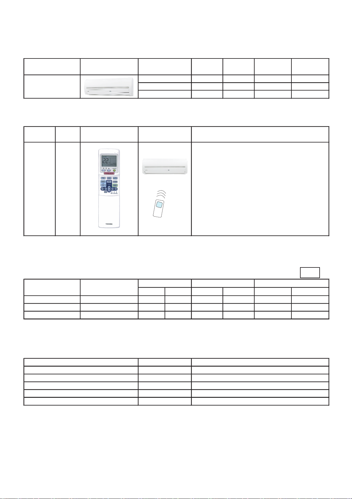
1. Equipments
1-1. Line up
Type Appearance
High Wall type
(2 series)
1-2. Remote controller
Name
Wireless remote controller
Model
name
WH-H2UE
(Note.1) Super MMS can not accept “AUTO” mode, Super HRM can accept “AUTO” mode.
Appearance Application
Model Name
MMK-AP0072H 007 type 0.8 2.2 2.5
MMK-AP0092H 009 type 1.0 2.8 3.2
MMK-AP0122H 012 type 1.25 3.6 4.0
(Packed with the indoor unit)
Capacity Capacity
rank code
・
Start / Stop
・
Changing mode
・
Temperature setting
・
Air flow changing (5 step)
・
Clock
・
Timer function
- ON/OFF timer (10 min. step)
- Everyday timer
・
High power mode
・
ECO mode (Sleep timer wtih ECO-logic)
・
One-touch pre-set memory
・
One-touch Auto (*1)
Cooling Heating
Capacity (kW) Capacity (kW)
Function
1-3. Wiring Design
50Hz
Model
MMK-AP0072H 230-1-50 198 264 0.03 0.20 0.24 15
MMK-AP0092H 230-1-50 198 264 0.03 0.21 0.26 15
MMK-AP0122H 230-1-50 198 264 0.03 0.22 0.27 15
Legend MCA : Minimum Circuit Amps FLA : Full Load Amps
MOCP : Maximum Overcurrent Protection (Amps) kW : Fan Motor Rated Output (kW)
Nominal Voltage
(V-Ph-Hz) Min Max kW FLA MCA MOCP
Voltage
Fan Motor Power Supply
1-4. Accessories
Accessory parts name Model Remarks
Wired remote controller RBC-AMT21E
Simple remote controller RBC-AS21E
Wireless remote controller kit TCB-AX21E with separeted reciever unit
Central remote controller TCB-SC642TLE Max. 64 group / unit
Weekly timer RBC-AS21E Use with RBC-AMT21WE
Page 3
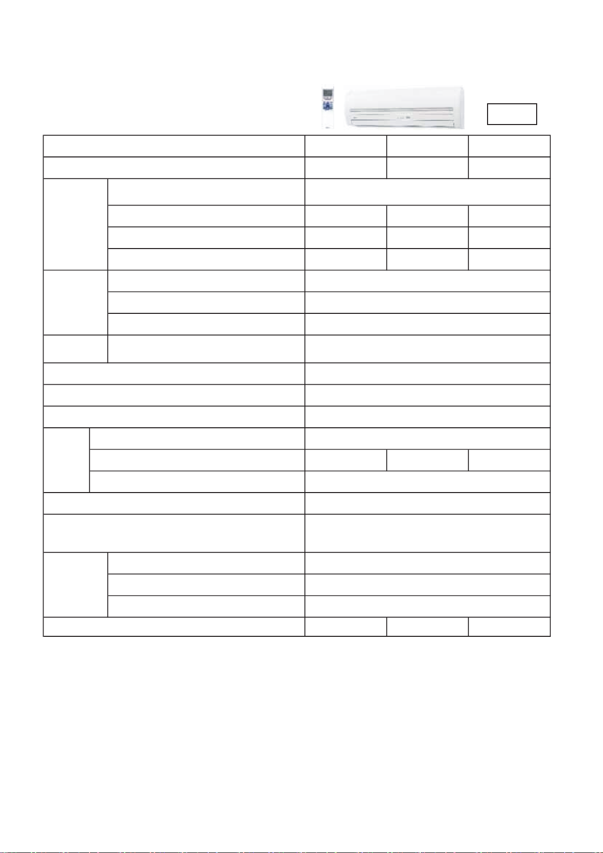
2. Technical Specifications
High Wall type (2 Series)
50Hz
Model name MMK- AP0072H AP0092H AP0122H
Cooling / Heating capacity (Note 1) (kW) 2.2 / 2.5 2.8 / 3.2 3.6 / 4.0
1 phase 50Hz 230V (220-240V)
(Power exclusive for indoor is required.)
Electrical
Characteristics
Power Supply
Running current (A) 0.17 0.18 0.19
Power consumption (kW) 0.017 0.018 0.019
Starting current (A) 0.22 0.23 0.24
Suction grille and side panel
Appearance
Discharge grille
Bottom surface
Outer
dimension
Height x Width x Depth (mm)
Total weight (kg)
Heat exchanger
Moon white
Moon white
Moon white
275 x 790 x 208
11
Finned tube
Soundproof/Heat-insulating material
Fan
Fan unit
Standard air flow (High/Mid/Low) (m3/h) 480 / 420 /360 510 / 450 / 360 540 / 450 / 360
Motor
Air filter
Controller (Note 3)
Gas side (mm)
Connecting
pipe
Liquid side (mm)
Drain port (Nominal dia.)
Non-flammable insulation
Cross-flow fan
30
Standard filter attached (Simple filter)
Wireless remote controller
(WH-H2UE, Packed with indoor unit)
9.5
6.4
17 (Polyvinyl chloride tube)
Sound level (Note 2) (High / Mid / Low) (dB(A)) 35-32-29 36-33-29 37-33-29
Note 1 :
Note 2 :
Note 3 :
4
Note :
The cooling capacities and electrical characteristics are measured under the conditions specified
by JIS B 8615 based on the reference piping. The reference piping consists of 5 m of main piping
and 2.5 m of branch piping connected with 0 meter height.
The sound level are measured in an anechoic chamber in accordance with JIS B8616.
Normally, the values measured in the actual operating environment become larger than
the indicated values due to the effects of external sound.
Wireless remote controller is packed with indoor unit.
Wired remote controller (RBC-AMT21E,RBC-AS21E) can be also connected.
Rated conditions Cooling : Indoor air temperature 27 C DB/19 C WB,
Outdoor air temperature 35 C DB
Heating : Indoor air temperature 20C
Outdoor air temperature 7C
DB,
DB/6C WB
2
Page 4
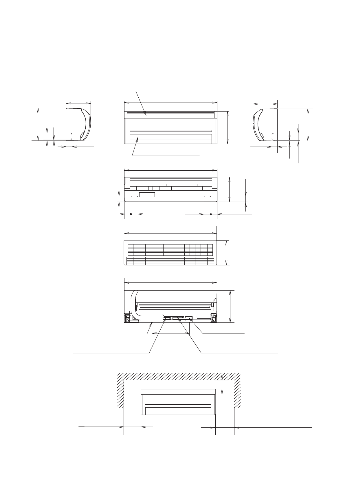
3. Dimensional Drawing
Model : MMK-AP0072H, AP0092H
208
275
48
6
60
Knockout
48
54.5
, AP0122H
Air inlet part
790
Air outlet gril
790
60
60
275
208
54.5
48
208
48
Knockout
275
6
60
Hock for insulation plate
Refrigerant pipe connecting port
Gas side φ9.5
(Installation space)
790
790
321
208
275
Drain pipe
Refrigerant pipe connecting port
Liquid side φ6.4
100mm or more
170mm or more
Note : All dimensions are in mm.
170mm or more
*300mm or more
*(For attached Flow Selector unit of
heat recovery model)
3
Page 5

4. Wiring Diagram
Model : MMK-AP0072H, AP0092H, AP0122H
4
Page 6

5. Refrigerant Cycle Diagram
Model : MMK-AP0072H, AP0092H, AP0122H
Liquid side
Strainer
Pulse Motor
Valve (PMV)
Gas side
Sensor
(TC2)
Capillary tube
Sensor
(TCJ)
Air hear exchanger
at indoor side
Fan
Sensor
(TA)
Sensor
(TC1)
Fan motor
Functional part name Functional outline
Pulse Moter PMV (Connector CN082 (6P): Blue)
Valve 1) Controls super heat in cooling operation
(PMV) 2) Controls under cool in heating operation
3) Recovers refrigerant oil in cooling operation
4) Recovers refrigerant oil in heating operation
Temp. sensor 1.TA (Connector CN104 (2P): Yellow)
1) Detects indoor suction temperature
2.TC1 (Connector CN100 (3P): Brown)
1) Controls PMV super heat in cooling operation
3.TC2 (Connector CN101 (2P): Black
1) Controls PMV under cool in heating operation
4.TCJ (Connector CN102 (2P): Red)
1) Controls PMV super heat in cooling operation
5
Page 7

6. Sensible Capacity Table
High Wall Type ( MMK-AP****2H ) 2 series
unit outdoor 14.0CWB 16.0CWB 18.0CWB 19.0CWB 20.0CWB 22.0CWB 24.0CWB
size air temp. 20CDB 23CDB 26CDB 27CDB 28CDB 30CDB 32CDB
CDB TC SHC TC SHC TC SHC TC SHC TC SHC TC SHC TC SHC
10.0 1.8 1.5 2.0 1.6 2.1 1.7 2.2 1.7 2.3 1.7 2.4 1.7 2.5 1.6
12.0 1.8 1.5 2.0 1.6 2.1 1.7 2.2 1.7 2.3 1.7 2.4 1.7 2.5 1.6
14.0 1.8 1.5 2.0 1.6 2.1 1.7 2.2 1.7 2.3 1.7 2.4 1.7 2.5 1.6
16.0 1.8 1.5 2.0 1.6 2.1 1.7 2.2 1.7 2.3 1.7 2.4 1.7 2.5 1.6
18.0 1.8 1.5 2.0 1.6 2.1 1.7 2.2 1.7 2.3 1.7 2.4 1.7 2.5 1.6
20.0 1.8 1.5 2.0 1.6 2.1 1.7 2.2 1.7 2.3 1.7 2.4 1.7 2.5 1.6
21.0 1.8 1.5 2.0 1.6 2.1 1.7 2.2 1.7 2.3 1.7 2.4 1.7 2.5 1.6
007 23.0 1.8 1.5 2.0 1.6 2.1 1.7 2.2 1.7 2.3 1.7 2.4 1.7 2.5 1.6
25.0 1.8 1.5 2.0 1.6 2.1 1.7 2.2 1.7 2.3 1.7 2.4 1.7 2.5 1.6
27.0 1.8 1.5 2.0 1.6 2.1 1.7 2.2 1.7 2.3 1.7 2.4 1.7 2.5 1.6
29.0 1.8 1.5 2.0 1.6 2.1 1.7 2.2 1.7 2.3 1.7 2.4 1.7 2.5 1.6
31.0 1.8 1.5 2.0 1.6 2.1 1.7 2.2 1.7 2.3 1.7 2.4 1.7 2.5 1.6
33.0 1.8 1.5 2.0 1.6 2.1 1.7 2.2 1.7 2.3 1.7 2.4 1.7 2.5 1.6
35.0 1.8 1.5 2.0 1.6 2.1 1.7 2.2 1.7 2.3 1.7 2.4 1.7 2.5 1.6
37.0 1.7 1.5 1.9 1.6 2.1 1.7 2.1 1.6 2.2 1.6 2.3 1.6 2.4 1.6
39.0 1.7 1.4 1.9 1.5 2.0 1.6 2.1 1.6 2.1 1.6 2.3 1.6 2.4 1.5
10.0 2.3 1.8 2.5 1.9 2.7 2.0 2.8 2.0 2.9 2.0 3.1 2.0 3.2 1.9
12.0 2.3 1.8 2.5 1.9 2.7 2.0 2.8 2.0 2.9 2.0 3.1 2.0 3.2 1.9
14.0 2.3 1.8 2.5 1.9 2.7 2.0 2.8 2.0 2.9 2.0 3.1 2.0 3.2 1.9
16.0 2.3 1.8 2.5 1.9 2.7 2.0 2.8 2.0 2.9 2.0 3.1 2.0 3.2 1.9
18.0 2.3 1.8 2.5 1.9 2.7 2.0 2.8 2.0 2.9 2.0 3.1 2.0 3.2 1.9
20.0 2.3 1.8 2.5 1.9 2.7 2.0 2.8 2.0 2.9 2.0 3.1 2.0 3.2 1.9
21.0 2.3 1.8 2.5 1.9 2.7 2.0 2.8 2.0 2.9 2.0 3.1 2.0 3.2 1.9
009 23.0 2.3 1.8 2.5 1.9 2.7 2.0 2.8 2.0 2.9 2.0 3.1 2.0 3.2 1.9
25.0 2.3 1.8 2.5 1.9 2.7 2.0 2.8 2.0 2.9 2.0 3.1 2.0 3.2 1.9
27.0 2.3 1.8 2.5 1.9 2.7 2.0 2.8 2.0 2.9 2.0 3.1 2.0 3.2 1.9
29.0 2.3 1.8 2.5 1.9 2.7 2.0 2.8 2.0 2.9 2.0 3.1 2.0 3.2 1.9
31.0 2.3 1.8 2.5 1.9 2.7 2.0 2.8 2.0 2.9 2.0 3.1 2.0 3.2 1.9
33.0 2.3 1.8 2.5 1.9 2.7 2.0 2.8 2.0 2.9 2.0 3.1 2.0 3.2 1.9
35.0 2.3 1.8 2.5 1.9 2.7 2.0 2.8 2.0 2.9 2.0 3.1 2.0 3.2 1.9
37.0 2.2 1.7 2.5 1.8 2.6 1.9 2.7 1.9 2.8 1.9 3.0 1.9 3.1 1.9
39.0 2.2 1.7 2.4 1.8 2.6 1.9 2.6 1.9 2.7 1.9 2.9 1.9 3.0 1.8
10.0 3.0 2.2 3.3 2.4 3.5 2.5 3.6 2.5 3.7 2.5 3.9 2.5 4.1 2.4
12.0 3.0 2.2 3.3 2.4 3.5 2.5 3.6 2.5 3.7 2.5 3.9 2.5 4.1 2.4
14.0 3.0 2.2 3.3 2.4 3.5 2.5 3.6 2.5 3.7 2.5 3.9 2.5 4.1 2.4
16.0 3.0 2.2 3.3 2.4 3.5 2.5 3.6 2.5 3.7 2.5 3.9 2.5 4.1 2.4
18.0 3.0 2.2 3.3 2.4 3.5 2.5 3.6 2.5 3.7 2.5 3.9 2.5 4.1 2.4
20.0 3.0 2.2 3.3 2.4 3.5 2.5 3.6 2.5 3.7 2.5 3.9 2.5 4.1 2.4
21.0 3.0 2.2 3.3 2.4 3.5 2.5 3.6 2.5 3.7 2.5 3.9 2.5 4.1 2.4
012 23.0 3.0 2.2 3.3 2.4 3.5 2.5 3.6 2.5 3.7 2.5 3.9 2.5 4.1 2.4
25.0 3.0 2.2 3.3 2.4 3.5 2.5 3.6 2.5 3.7 2.5 3.9 2.5 4.1 2.4
27.0 3.0 2.2 3.3 2.4 3.5 2.5 3.6 2.5 3.7 2.5 3.9 2.5 4.1 2.4
29.0 3.0 2.2 3.3 2.4 3.5 2.5 3.6 2.5 3.7 2.5 3.9 2.5 4.1 2.4
31.0 3.0 2.2 3.3 2.4 3.5 2.5 3.6 2.5 3.7 2.5 3.9 2.5 4.1 2.4
33.0 3.0 2.2 3.3 2.4 3.5 2.5 3.6 2.5 3.7 2.5 3.9 2.5 4.1 2.4
35.0 3.0 2.2 3.3 2.4 3.5 2.5 3.6 2.5 3.7 2.5 3.9 2.5 4.1 2.4
37.0 2.9 2.1 3.2 2.3 3.4 2.4 3.5 2.4 3.6 2.4 3.8 2.4 4.0 2.3
39.0 2.8 2.1 3.1 2.2 3.3 2.4 3.4 2.4 3.5 2.4 3.7 2.3 3.9 2.3
TC : Total capacity [kW] SHC : Sensible capacity [kW]
Indoor Air Temp.
6
Page 8

7. Fan Characteristics
Discharge Air Speed and Air Throw
High Wall Type (2 series)
Model : MMK-AP0072H, AP0092H, AP0122H
Horizontal discharge Initial speed
5
4
3
2
1
Air speed (m/s)
0
0
1
2
3 4 5 6 7
Horizontal throw (m)
High wind : 4.5m/s
Med wind : 3.7m/s
Low wind : 3.2m/s
High
Mid
Low
7
Page 9

8. Sound Characteristics (NC curve)
High Wall Type (2 series)
Model : MMK-AP0072H, AP0092H, AP0122H
1m
Microphone
1m
MMK-AP0072H
90
80
70
60
50
(dB)
40
30
20
Octave band sound pressure level
10
20~75
Audifility limits
of continous
white level
75~150
Fan tap H M L
Sound pressure level (dB(A)) 35 32 29
NC-70
NC-60
NC-50
NC-40
NC-30
NC-20
150~300 300~600 600~1200 1200~2400 2400~4800
4800~10000
Octave band frequency (Hz)
8
Page 10

MMK-AP0092H
90
80
Fan tap H M L
Sound pressure level (dB(A)) 36 33 29
70
60
50
40
30
20
Octave band sound pressure level (dB)
Audifility limits
of continous
white level
10
~
20 75 75 ~ 150 150 ~300 300 ~ 600 600 ~ 1200 1200 ~2400 2400 ~ 4800 4800 ~ 10000
Octave band frequency (Hz)
MMK-AP0122H
Fan tap H M L
Sound pressure level (dB(A)) 37 33 29
NC-70
NC-60
NC-50
NC-40
NC-30
NC-20
90
80
70
60
50
(dB)
40
30
20
Octave band sound pressure level
10
20~75 75~150
Audifility limits
of continous
white level
150~300
300~600 600~1200 1200~2400
Octave band frequency (Hz)
2400~4800
NC-70
NC-60
NC-50
NC-40
NC-30
NC-20
4800~10000
9
Page 11

9. Wireless Remote controller
External View
Function
Start/Stop
Setting
temp.
AUTO C C
COOL C C
DRY C C
HEAT C C
Fahrenheit display
Air Volume Control
Frap
Swing
Operation select
High wall (1 series)
TCB-AX21E
(Sold Separately)
High Wall (2 series)
WH-H2UE
Button Contents Button Contents Remarks
Start/Stop OK START/STOP OK
17~27
18~30
18~30
16~26
- - -
OK
3-Speed, Auto FAN 5-Speed, Auto
Swing/Frap
OK
Auto, Heat, Dry, Cool,
Fan
FIX OK
SWING OK
MODE
17~30
17~30
17~30
17~30
Auto,Cool,Dry,
Heat, Fan
No Fahrenheit display function
5-step control
No switch setting for cooling
only
One-touch auto ( Auto mode,
One-touch Auto
Preset mode
Clock
ON/OFF timer
ECONO mode
Everyday timer
Timer cancel
High Power mode
Filter reset
Reset
Sensor button
-
-
-
-
AUTO
MEMO /
PRESET
One-touch
OK
- - CLOCK OK
OFF timer, ON timer,
SET
Repeat timer,
30 minutes interval,
ON/OFF/SET
max. 72 hours,
- OK
-
ECO
Clock display
minutes interval,
10
max.
24 hours,
- - ON/OFF/SET OK
CL OK OK
- - Hi-POWER OK
Filter reset OK OK
Reset OK OK
FILTER
RESET
SENSOR OK - -
system,
Setting temperature :22 C, Air
Auto
volume : Auto, Frap position :
Auto, Swing : Off)
Memorizing of setting contents
for preset mode freely.
Available for ON / OFF working
together
Sleep timer with ECO logic
Setting both ON and OFF timer
simultaneously and active every
day.
Automatic controls for quick
cooling and heating
No remote controller sensor
-
-
-
(Note)
1. Automatic operation mode can not be accepted by heat pump system. If trainsmission is sent as auto mode, operation lamp
and timer lamp of the indoor unit will light up with the beep as the notice. In this case, change the other operation mode to release
the notice. ( Heat recovery system can accept automatic operation by using this wireless remote controller.)
2. Group control by using the wired remote controller (WH-H2UE) is not available. If it is done, incorrect action or display
disagreement may occur.
3. A wired remote controller is required for the group control. (sold separately.)
4. When the wired remote controller is connected to this high wall unit, two remote control with the wireless remote controller
(WH-H2UE) is also available. In this case, last-push priority control is performed.
5. When the group control by the wired remote controller is conducted, ECO-Timer and Hi-POWER operation will not function.
10
 Loading...