

Toshiba MMD-AP0186BHP1-E, MMD-AP0126BHP1-E, MMD-AP0246BHP1-E, MMD-AP0276BHP1-E, MMD-AP0306BHP1-E Service Manual
...
SERVICE MANUAL
AIR-CONDITIONER
MULTI TYPE
INDOOR UNIT
< Concealed Duct Standard Type >
FILE NO. SVM-16043
MMD-AP0076BHP1-E
MMD-AP0096BHP1-E
MMD-AP0126BHP1-E
MMD-AP0156BHP1-E
MMD-AP0186BHP1-E
MMD-AP0246BHP1-E
MMD-AP0276BHP1-E
MMD-AP0306BHP1-E
MMD-AP0366BHP1-E
MMD-AP0486BHP1-E
MMD-AP0566BHP1-E
MMD-AP0076BHP1-TR
MMD-AP0096BH
MMD-AP0126BHP1-TR
MMD-AP0156BHP1-TR
MMD-AP0186BHP1-TR
MMD-AP02
MMD-AP0276BHP1-TR
MMD-AP0306BHP1-TR
MMD-AP0366BHP1-TR
MMD-AP0486BHP1-TR
MMD-AP0566BHP1-TR
46BHP1-TR
P1-TR
R410A
April
201
6

CONTENTS
PRECAUTIONS FOR SAFETY ................................................................................ 6
1. SPECIFICATIONS .................................................................................................. 13
2. AIR DUCTING WORK............................................................................................. 15
3. CONSTRUCTION VIEWS (EXTERNAL VIEWS).................................................... 17
4. WIRING DIAGRAMS............................................................................................... 19
5. PARTS RATING...................................................................................................... 20
6. REFRIGERANT CYCLE DIAGRAM ....................................................................... 21
7. CONTROL OUTLINE.............................................................................................. 22
8. APPLIED CONTROL AND FUNCTIONS
(INCLUDING CIRCUIT CONFIGURATION) .......................................................... 28
8-1. Indoor controller block diagram ........................................................................................ 28
8-1-1. In Case of Connection of Wired (Simple) Remote Controller ............................. 28
8-1-2. In Case of Connection of Wireless Remote Controller ....................................... 29
8-1-3. Connection of Both Wired (Simple) Remote Controller and Wireless Remote
Controller ................................................................................................................ 30
8-2. Indoor Print Circuit Board MCC-1631 ...............
Optional connector specifications of indoor P.C. board................................................. 32
8-3.
8-4. Test operation of indoor unit .............................................................................................33
8-5. Method to set indoor unit function DN code .................................................................... 34
8-6. Applied control of indoor unit ........................................................................................... 37
9. TROUBLESHOOTING............................................................................................ 53
9-1. Overview .............................................................................................................................. 53
9-2. Troubleshooting method ....................................................................................................54
9-3. Troubleshooting based on information displayed on remote controller ....................... 60
9-4. Check codes displayed on remote controller and SMMS outdoor unit
(7-segment display on I/F board) and locations to be checked .................................... 65
9-5. Sensor characteristics ....................................................................................................... 84
10. P.C. BOARD EXCHANGE PROCEDURES.......................................................... 85
10-1. Replacement of indoor P.C. boards................................................................................. 85
11. DETACHMENTS................................................................................................... 91
12. EXPLODED VIEWS AND PARTS LIST ............................................................... 98
................................................................ 31
– 2 –

Original instruction
Please read carefully through these instructions that contain important information which complies with the
“Machinery” Directive (Directive 2006/42/EC), and ensure that you understand them.
Generic Denomination: Air Conditioner
Definition of Qualified Installer or Qualified Service Person
The air conditioner must be installed, maintained, repaired and removed by a qualified installer or qualified
service person. When any of these jobs is to be done, ask a qualified installer or qualified service person to do
them for you.
A qualified installer or qualified service person is an agent who has the qualifications and knowledge
described in the table below.
Agent Qualifications and knowledge which the agent must have
• The qualified installer is a person who installs, maintains, relocates and removes the air
conditioners made by Toshiba Carrier Corporation. He or she has been trained to install,
maintain, relocate and remove the air conditioners made by Toshiba Carrier Corporation or,
alternatively, he or she has been instructed in such operations by an individual or individuals
who have been trained and is thus thoroughly acquainted with the knowledge related to these
operations.
• The qualified installer who is allowed to do the electrical work involved in installation, relocation
and removal has the qualifications pertaining to this electrical work as stipulated by the local
laws and regulations, and he or she is a person who has been trained in matters relating to
electrical work on the air conditioners made by Toshiba Carrier Corporation or, alternatively, he
Qualified installer
or she has been instructed in such matters by an individual or individuals who have been
trained and is thus thoroughly acquainted with the knowledge related to this work.
• The qualified installer who is allowed to do the refrigerant handling and piping work involved in
installation, relocation and removal has the qualifications pertaining to this refrigerant handling
and piping work as stipulated by the local laws and regulations, and he or she is a person who
has been trained in matters relating to refrigerant handling and piping work on the air
conditioners made by Toshiba Carrier Corporation or, alternatively, he or she has been
instructed in such matters by an individual or individuals who have been trained and is thus
thoroughly acquainted with the knowledge related to this work.
• The qualified installer who is allowed to work at heights has been trained in matters relating to
working at heights with the air conditioners made by Toshiba Carrier Corporation or,
alternatively, he or she has been instructed in such matters by an individual or individuals who
have been trained and is thus thoroughly acquainted with the knowledge related to this work.
Qualified service
person
• The qualified service person is a person who installs, repairs, maintains, relocates and removes
the air conditioners made by Toshiba Carrier Corporation. He or she has been trained to install,
repair, maintain, relocate and remove the air conditioners made by Toshiba Carrier Corporation
or, alternatively, he or she has been instructed in such operations by an individual or individuals
who have been trained and is thus thoroughly acquainted with the knowledge related to these
operations.
• The qualified service person who is allowed to do the electrical work involved in installation,
repair, relocation and removal has the qualifications pertaining to this electrical work as
stipulated by the local laws and regulations, and he or she is a person who has been trained in
matters relating to electrical work on the air conditioners made by Toshiba Carrier Corporation
or, alternatively, he or she has been instructed in such matters by an individual or individuals
who have been trained and is thus thoroughly acquainted with the knowledge related to this
work.
• The qualified service person who is allowed to do the refrigerant handling and piping work
involved in installation, repair, relocation and removal has the qualifications pertaining to this
refrigerant handling and piping work as stipulated by the local laws and regulations, and he or
she is a person who has been trained in matters relating to refrigerant handling and piping work
on the air conditioners made by Toshiba Carrier Corporation or, alternatively, he or she has
been instructed in such matters by an individual or individuals who have been trained and is
thus thoroughly acquainted with the knowledge related to this work.
• The qualified service person who is allowed to work at heights has been trained in matters
relating to working at heights with the air conditioners made by Toshiba Carrier Corporation or,
alternatively, he or she has been instructed in such matters by an individual or individuals who
have been trained and is thus thoroughly acquainted with the knowledge related to this work.
– 3 –
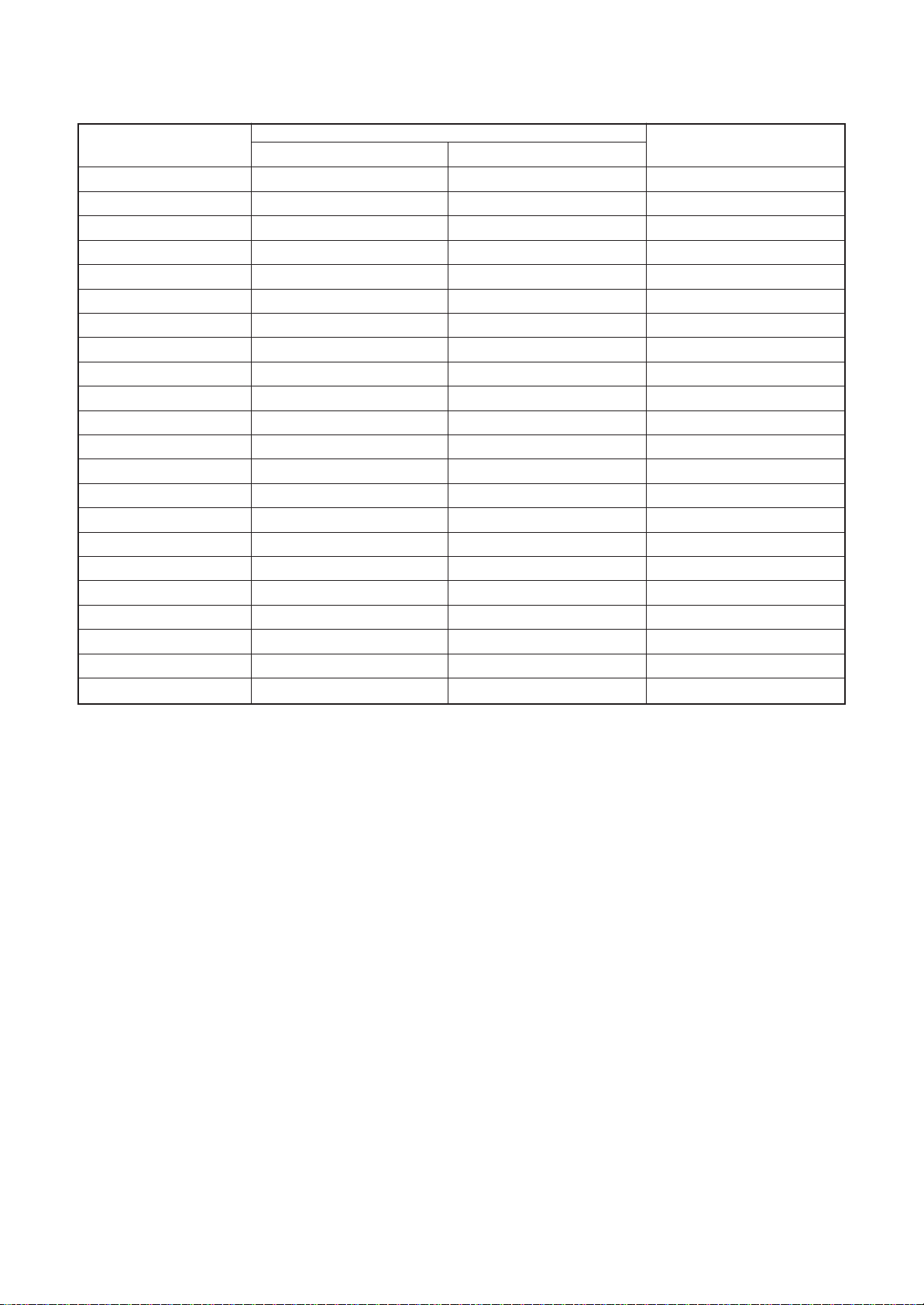
Definition of Protective Gear
When the air conditioner is to be transported, installed, maintained, repaired or removed, wear protective
gloves and ‘safety’ work clothing.
In addition to such normal protective gear, wear the protective gear described below when undertaking the
special work detailed in the table below.
Failure to wear the proper protective gear is dangerous because you will be more susceptible to injury, burns,
electric shocks and other injuries.
Work undertaken
All types of work
Electrical-related work
Work done at heights
(50 cm or more)
Transportation of heavy objects
Repair of outdoor unit
Protective gloves
‘Safety’ working clothing
Gloves to provide protection for electricians and from heat
Insulating shoes
Clothing to provide protection from electric shock
Helmets for use in industry
Shoes with additional protective toe cap
Gloves to provide protection for electricians and from heat
Protective gear worn
The important contents concerned to the safety are described on the product itself and on this Service
Manual.
Please read this Service Manual after understanding the described items thoroughly in the following contents
(Indications / Illustrated marks), and keep them.
[Explanation of indications]
Indication Explanation
DANGER
WARNING
CAUTION
Indicates contents assumed that an imminent danger causing a death or serious injury of
the repair engineers and the third parties when an incorrect work has been executed.
Indicates possibilities assumed that a danger causing a death or serious injury of the
repair engineers, the third parties, and the users due to troubles of the product after work
when an incorrect work has been executed.
Indicates contents assumed that an injury or property damage (*) may be caused on the
repair engineers, the third parties, and the users due to troubles of the product after work
when an incorrect work has been executed.
* Property damage: Enlarged damage concerned to property, furniture, and domestic animal / pet
[Explanation of illustrated marks]
Indication Explanation
Indicates prohibited items (Forbidden items to do)
The sentences near an illustrated mark describe the concrete prohibited contents.
Indicates mandatory items (Compulsory items to do)
The sentences near an illustrated mark describe the concrete mandatory contents.
Indicates cautions (Including danger / warning)
The sentences or illustration near or in an illustrated mark describe the concrete cautious contents.
– 4 –

Warning Indications on the Air Conditioner Unit
[Confirmation of warning label on the main unit]
Confirm that labels are indicated on the specified positions
If removing the label during parts replace, stick it as the original.
Warning indication Description
WARNING
ELECTRICAL SHOCK HAZARD
Disconnect all remote electric
power supplies before servicing.
WARNING
Moving parts.
Do not operate unit with grille removed.
Stop the unit before the servicing.
CAUTION
High temperature parts.
You might get burned when removing
this panel.
WARNING
ELECTRICAL SHOCK HAZARD
Disconnect all remote electric power supplies
before servicing.
WARNING
Moving parts.
Do not operate unit with grille removed.
Stop the unit before the servicing.
CAUTION
High temperature parts.
You might get burned when removing this panel.
CAUTION
Do not touch the aluminium fins of the unit.
Doing so may result in injury.
CAUTION
BURST HAZARD
Open the service valves before the
operation, otherwise there might be the
burst.
CAUTION
Do not climb onto the fan guard.
Doing so may result in injury.
CAUTION
Do not touch the aluminium fins of the unit.
Doing so may result in injury.
CAUTION
BURST HAZARD
Open the service valves before the operation,
otherwise there might be the burst.
CAUTION
Do not climb onto the fan guard.
Doing so may result in injury.
– 5 –
PRECAUTIONS FOR SAFETY
The manufacturer shall not assume any liability for the damage caused by not observing the description of this
manual.
DANGER
Before carrying out the installation, maintenance, repair or removal work, be sure to set the circuit
breaker for both the indoor and outdoor units to the OFF position. Otherwise, electric shocks may
result.
Before opening the electrical box cover of the indoor unit or service panel of the outdoor unit, set the
circuit breaker to the OFF position. Failure to set the circuit breaker to the OFF position may result in
electric shocks through contact with the interior parts. Only a qualified installer (*1) or qualified service
person (*1) is allowed to remove the intake grille of the indoor unit or service panel of the outdoor unit
and do the work required.
Before opening the suction board cover, set the circuit breaker to the OFF position.
Failure to set the circuit breaker to the OFF position may result in injury through contact with the rotation parts.
Only a qualified installer (*1) or qualified service person (*1) is allowed to remove the suction board
Tu r n o f f
braeaker
Electric
shock hazard
Prohibition
Stay on
protection
cover and do the work required.
Before starting to repair the outdoor unit fan or fan guard, be absolutely sure to set the circuit breaker
to the OFF position, and place a “Work in progress” sign on the circuit breaker.
When cleaning the filter or other parts of the indoor unit, set the circuit breaker to OFF without fail, and
place a “Work in progress” sign near the circuit breaker before proceeding with the work.
When you have noticed that some kind of trouble (such as when an error display has appeared, there
is a smell of burning, abnormal sounds are heard, the air conditioner fails to cool or heat or water is
leaking) has occurred in the air conditioner, do not touch the air conditioner yourself but set the circuit
breaker to the OFF position, and contact a qualified service person. Take steps to ensure that the
power will not be turned on (by marking “out of service” near the circuit breaker, for instance) until
qualified service person arrives. Continuing to use the air conditioner in the trouble status may cause
mechanical problems to escalate or result in electric shocks or other failure.
When you access inside of the service panel to repair electric parts, wait for about five minutes after turning
off the breaker. Do not start repairing immediately.Otherwise you may get electric shock by touching
terminals of high-voltage capacitors. Natural discharge of the capacitor takes about five minutes.
When checking the electric parts, removing the cover of the electric parts box of Indoor Unit and/or
service panel of Outdoor Unit inevitably to determine the failure, use gloves to provide protection for
electricians, insulating shoes, clothing to provide protection from electric shock and insulating tools. Be
careful not to touch the live part. Electric shock may result. Only “Qualified service person” is allowed to
do this work.
Place a “Work in progress” sign near the circuit breaker while the installation, maintenance, repair or
removal work is being carried out.
There is a danger of electric shocks if the circuit breaker is set to ON by mistake.
When checking the electric parts, removing the cover of the electric parts box of Indoor Unit and/or
front panel of Outdoor Unit inevitably to determine the failure, put a sign “Do not enter” around the site
before the work. Failure to do this may result in third person getting electric shock.
Before operating the air conditioner after having completed the work, check that the electrical parts box
cover of the indoor unit and service panel of the outdoor unit are closed, and set the circuit breaker to
the ON position.
You may receive an electric shock if the power is turned on without first conducting these checks.
If, in the course of carrying out repairs, it becomes absolutely necessary to check out the electrical
parts with the electrical parts box cover of one or more of the indoor units and the service panel of the
outdoor unit removed in order to find out exactly where the trouble lies, wear insulated heat-resistant
gloves, insulated boots and insulated work overalls, and take care to avoid touching any live parts.
You may receive an electric shock if you fail to heed this warning. Only qualified service person (*1) is
allowed to do this kind of work.
– 6 –
WARNIG
General
Before starting to repair the air conditioner, read carefully through the Service Manual, and repair the
air conditioner by following its instructions.
Only qualified service person (*1) is allowed to repair the air conditioner.
Repair of the air conditioner by unqualified person may give rise to a fire, electric shocks, injury, water
leaks and / or other problems.
Do not use any refrigerant different from the one specified for complement or replacement.
Otherwise, abnormally high pressure may be generated in the refrigeration cycle, which may result in a
failure or explosion of the product or an injury to your body.
Only a qualified installer (*1) or qualified service person (*1) is allowed to carry out the electrical work
of the air conditioner.
Under no circumstances must this work be done by an unqualified individual since failure to carry out
the work properly may result in electric shocks and / or electrical leaks.
When the air conditioner is to be transported, installed, maintained, repaired or removed, wear
protective gloves and ‘safety’ work clothing.
To connect the electrical wires, repair the electrical parts or undertake other electrical jobs, wear gloves
to provide protection for electricians, insulating shoes and clothing to provide protection from electric
shocks. Failure to wear this protective gear may result in electric shocks.
Electrical wiring work shall be conducted according to law and regulation in the community and
installation manual. Failure to do so may result in electrocution or short circuit.
Use wiring that meets the specifications in the Installation Manual and the stipulations in the local
regulations and laws. Use of wiring which does not meet the specifications may give rise to electric
shocks, electrical leakage, smoking and/or a fire.
Only a qualified installer (*1) or qualified service person (*1) is allowed to undertake work at heights
using a stand of 50 cm or more or to remove the intake grille of the indoor unit to undertake work.
When working at heights, use a ladder which complies with the ISO 14122 standard, and follow the
procedure in the ladder’s instructions.
Also wear a helmet for use in industry as protective gear to undertake the work.
Before working at heights, put a sign in place so that no-one will approach the work location,
before proceeding with the work. Parts and other objects may fall from above, possibly injuring a
person below. While carrying out the work, wear a helmet for protection from falling objects.
When executing address setting, test run, or troubleshooting through the checking window on the
electric parts box, put on insulated gloves to provide protection from electric shock. Otherwise you may
receive an electric shock.
When the first filter comes out without connected to the other one, insert it once more to connectthe
two filters together and pull out them as connected. Do not insert hands to take out the second filter.
You may injure Yourself.
Do not touch the aluminum fin of the outdoor unit.
You may injure yourself if you do so. If the fin must be touched for some reason, first put on protective
gloves and safety work clothing, and then proceed.
Do not climb onto or place objects on top of the outdoor unit.
You may fall or the objects may fall off of the outdoor unit and result in injury.
Use forklift to carry in the air conditioner units and use winch or hoist at installation of them.
When transporting the air conditioner, wear shoes with protective toe caps, protective gloves and other
protective clothing.
When transporting the air conditioner, do not take hold of the bands around the packing carton.
You may injure yourself if the bands should break.
Be sure that a heavy unit (10 kg or heavier) such as a compressor is carried by two persons.
This air conditioner has passed the pressure test as specified in IEC 60335-2-40 Annex EE.
Check earth
wires.
Before troubleshooting or repair work, check the earth wire is connected to the earth terminals of the main unit,
otherwise an electric shock is caused when a leak occurs.If the earth wire is not correctly connected,
contact an electric engineer for rework.
After completing the repair or relocation work, check that the ground wires are connected properly.
Be sure to connect earth wire. (Grounding work) Incomplete grounding causes an electric shock.
Do not connect ground wires to gas pipes, water pipes, and lightning rods or ground wires for
telephone wires.
– 7 –
Prohibition of
modification.
Use specified
parts.
Do not bring
a child close
to the
equipment.
Insulating
measures
No fire
Refrigerant
Do not modify the products.Do not also disassemble or modify the parts.
It may cause a fire, electric shock or injury.
When any of the electrical parts are to be replaced, ensure that the replacement parts satisfy the
specifications given in the Service Manual (or use the parts contained on the parts list in the
Service Manual).
Use of any parts which do not satisfy the required specifications may give rise to electric shocks,
smoking and / or a fire.
If, in the course of carrying out repairs, it becomes absolutely necessary to check out the electrical
parts with the electrical parts box cover of one or more of the indoor units and the service panel of the
outdoor unit removed in order to find out exactly where the trouble lies, put a sign in place so that noone will approach the work location before proceeding with the work. Third-party individuals may enter
the work site and receive electric shocks if this warning is not heeded.
Connect the cut-off lead wires with crimp contact, etc., put the closed end side upward and then apply
a watercut method, otherwise a leak or production of fire is caused at the users’ side.
When performing repairs using a gas burner, replace the refrigerant with nitrogen gas because the oil
that coats the pipes may otherwise burn.
When repairing the refrigerating cycle, take the following measures.
1) Be attentive to fire around the cycle. When using a gas stove, etc., be sure to put out fire before work;
otherwise the oil mixed with refrigerant gas may catch fire.
2) Do not use a welder in the closed room. When using it without ventilation, carbon monoxide
poisoning may be caused.
3) Do not bring inflammables close to the refrigerant cycle, otherwise fire of the welder may catch the
inflammables.
The refrigerant used by this air conditioner is the R410A.
Check the used refrigerant name and use tools and materials of the parts which match with it.
For the products which use R410A refrigerant, the refrigerant name is indicated at a position on the
outdoor unit where is easy to see. To prevent miss-charging, the route of the service port is changed
from one of the former R22.
Do not use any refrigerant different from the one specified for complement or replacement.
Otherwise, abnormally high pressure may be generated in the refrigeration cycle, which may result in a
failure or explosion of the product or an injury to your body.
For an air conditioner which uses R410A, never use other refrigerant than R410A. For an air
conditioner which uses other refrigerant (R22, etc.), never use R410A.
If different types of refrigerant are mixed, abnormal high pressure generates in the refrigerating cycle
and an injury due to breakage may be caused.
When the air conditioner has been installed or relocated, follow the instructions in the Installation
Manual and purge the air completely so that no gases other than the refrigerant will be mixed in the
refrigerating cycle.
Failure to purge the air completely may cause the air conditioner to malfunction.
Do not charge refrigerant additionally. If charging refrigerant additionally when refrigerant gas leaks, the
refrigerant composition in the refrigerating cycle changes resulted in change of air conditioner
characteristics or refrigerant over the specified standard amount is charged and an abnormal high
pressure is applied to the inside of the refrigerating cycle resulted in cause of breakage or injury.
Therefore if the refrigerant gas leaks, recover the refrigerant in the air conditioner, execute vacuuming,
and then newly recharge the specified amount of liquid refrigerant.
In this time, never charge the refrigerant over the specified amount.
When recharging the refrigerant in the refrigerating cycle, do not mix the refrigerant or air other than
R410A into the specified refrigerant. If air or others is mixed with the refrigerant, abnormal high
pressure generates in the refrigerating cycle resulted in cause of injury due to breakage.
After installation work, check the refrigerant gas does not leak. If the refrigerant gas leaks in the room,
poisonous gas generates when gas touches to fire such as fan heater, stove or cocking stove though
the refrigerant gas itself is innocuous.
Never recover the refrigerant into the outdoor unit. When the equipment is moved or repaired, be sure
to recover the refrigerant with recovering device.
The refrigerant cannot be recovered in the outdoor unit; otherwise a serious accident such as breakage
or injury is caused.
– 8 –
Assembly /
Wiring
Insulator
check
Ventilation
Compulsion
Check after
repair
After repair work, surely assemble the disassembled parts, and connect and lead the removed wires as before.
Perform the work so that the cabinet or panel does not catch the inner wires.
If incorrect assembly or incorrect wire connection was done, a disaster such as a leak or fire is caused
at user’s side.
After the work has finished, be sure to use an insulation tester set (500 V Megger) to check the resistance is
1 MΩ or more between the charge section and the non-charge metal section (Earth position).
If the resistance value is low, a disaster such as a leak or electric shock is caused at user’s side.
When the refrigerant gas leaks during work, execute ventilation.
If the refrigerant gas touches to a fire, poisonous gas generates. A case of leakage of the refrigerant
and the closed room full with gas is dangerous because a shortage of oxygen occurs. Be sure to
execute ventilation.
If refrigerant gas has leaked during the installation work, ventilate the room immediately.
If the leaked refrigerant gas comes in contact with fire, noxious gas may generate.
After installation work, check the refrigerant gas does not leak. If the refrigerant gas leaks in the room,
poisonous gas generates when gas touches to fire such as fan heater, stove or cocking stove though
the refrigerant gas itself is innocuous.
When the refrigerant gas leaks, find up the leaked position and repair it surely.
If the leaked position cannot be found up and the repair work is interrupted, pump-down and tighten the
service valve, otherwise the refrigerant gas may leak into the room.
The poisonous gas generates when gas touches to fire such as fan heater, stove or cocking stove though
the refrigerant gas itself is innocuous.
When installing equipment which includes a large amount of charged refrigerant such as a multi air
conditioner in a sub-room, it is necessary that the density does not the limit even if the refrigerant leaks.
If the refrigerant leaks and exceeds the limit density, an accident of shortage of oxygen is caused.
Tighten the flare nut with a torque wrench in the specified manner.
Excessive tighten of the flare nut may cause a crack in the flare nut after a long period, which may
result in refrigerant leakage.
Nitrogen gas must be used for the airtight test.
The charge hose must be connected in such a way that it is not slack.
For the installation / moving / reinstallation work, follow to the Installation Manual.
If an incorrect installation is done, a trouble of the refrigerating cycle, water leak, electric shock or fire is caused.
Once the repair work has been completed, check for refrigerant leaks, and check the insulation
resistance and water drainage.
Then perform a trial run to check that the air conditioner is running properly.
After repair work has finished, check there is no trouble. If check is not executed, a fire, electric shock
or injury may be caused. For a check, turn off the power breaker.
After repair work (installation of front panel and cabinet) has finished, execute a test run to check there
is no generation of smoke or abnormal sound.
If check is not executed, a fire or an electric shock is caused. Before test run, install the front panel and cabinet.
Be sure to fix the screws back which have been removed for installation or other purposes.
Do not
operate the
unit with the
valve closed.
Check after
reinstallation
Check the following matters before a test run after repairing piping.
• Connect the pipes surely and there is no leak of refrigerant.
• The valve is opened.
Running the compressor under condition that the valve closes causes an abnormal high pressure
resulted in damage of the parts of the compressor and etc. and moreover if there is leak of refrigerant
at connecting section of pipes, the air is sucked and causes further abnormal high pressure resulted in
burst or injury.
Only a qualified installer (*1) or qualified service person (*1) is allowed to relocate the air conditioner. It
is dangerous for the air conditioner to be relocated by an unqualified individual since a fire, electric
shocks, injury, water leakage, noise and / or vibration may result.
Check the following items after reinstallation.
1) The earth wire is correctly connected.
2) The power cord is not caught in the product.
3) There is no inclination or unsteadiness and the installation is stable.
If check is not executed, a fire, an electric shock or an injury is caused.
When carrying out the pump-down work shut down the compressor before disconnecting the refrigerant pipe.
Disconnecting the refrigerant pipe with the service valve left open and the compressor still operating
will cause air, etc. to be sucked in, raising the pressure inside the refrigeration cycle to an abnormally
high level, and possibly resulting in reputing, injury, etc.
– 9 –
Cooling check
Installation
When the service panel of the outdoor unit is to be opened in order for the compressor or the area
around this part to be repaired immediately after the air conditioner has been shut down, set the circuit
breaker to the OFF position, and then wait at least 10 minutes before opening the service panel.
If you fail to heed this warning, you will run the risk of burning yourself because the compressor pipes
and other parts will be very hot to the touch. In addition, before proceeding with the repair work, wear
the kind of insulated heat-resistant gloves designed to protect electricians.
Take care not to get burned by compressor pipes or other parts when checking the cooling cycle while
running the unit as they get heated while running. Be sure to put on gloves providing protection for heat.
When the service panel of the outdoor unit is to be opened in order for the fan motor, reactor, inverter
or the areas around these parts to be repaired immediately after the air conditioner has been shut
down, set the circuit breaker to the OFF position, and then wait at least 10 minutes before opening the
service panel.
If you fail to heed this warning, you will run the risk of burning yourself because the fan motor, reactor,
inverter heat sink and other parts will be very hot to the touch.
In addition, before proceeding with the repair work, wear the kind of insulated heat-resistant gloves
designed to protect electricians.
Only a qualified installer or service person is allowed to do installation work. Inappropriate installation
may result in water leakage, electric shock or fire.
Before starting to install the air conditioner, read carefully through the Installation Manual, and follow its
instructions to install the air conditioner.
Be sure to use the company-specified products for the separately purchased parts. Use of nonspecified products may result in fire, electric shock, water leakage or other failure. Have the installation
performed by a qualified installer.
Do not supply power from the power terminal block equipped on the outdoor unit to another outdoor unit.
Capacity overflow may occur on the terminal block and may result in fire.
Do not install the air conditioner in a location that may be subject to a risk of expire to a combustible gas.
If a combustible gas leaks and becomes concentrated around the unit, a fire may occur.
Install the indoor unit at least 2.5 m above the floor level since otherwise the users may injure
themselves or receive electric shocks if they poke their fingers or other objects into the indoor unit
while the air conditioner is running.
Install a circuit breaker that meets the specifications in the installation manual and the stipulations in
the local regulations and laws.
Install the circuit breaker where it can be easily accessed by the qualified service person (*1).
If you install the unit in a small room, take appropriate measures to prevent the refrigerant from
exceeding the limit concentration even if it leaks. Consult the dealer from whom you purchased the air
conditioner when you implement the measures. Accumulation of highly concentrated refrigerant may
cause an oxygen deficiency accident.
Do not place any combustion appliance in a place where it is directly exposed to the wind of air
conditioner, otherwise it may cause imperfect combustion.
When mounting the rails, push them until the 3 latches click. (Concealed duct type only)
Insert the filters into the direction which the arrows, carved on the filters, show. (2 filters are identical)
Explanations given to user
If you have discovered that the fan grille is damaged, do not approach the outdoor unit but set the circuit
breaker to the OFF position, and contact a qualified service person to have the repairs done.
Do not set the circuit breaker to the ON position until the repairs are completed.
Relocation
• Only a qualified installer (*1) or qualified service person (*1) is allowed to relocate the air conditioner.
It is dangerous for the air conditioner to be relocated by an unqualified individual since a fire, electric shocks,
injury, water leakage, noise and / or vibration may result.
• When carrying out the pump-down work shut down the compressor before disconnecting the refrigerant pipe.
Disconnecting the refrigerant pipe with the service valve left open and the compressor still operating will
cause air, etc. to be sucked in, raising the pressure inside the refrigeration cycle to an abnormally high level,
and possibly resulting in reputing, injury, etc.
(*1) Refer to the “Definition of Qualified Installer or Qualified Service Person”
– 10 –

Declaration of Conformity
Manufacturer:
TOSHIBA CARRIER (THAILAND) CO., LTD.
144 / 9 Moo 5, Bangkadi Industrial Park, Tivanon Road,
Tambon Bangkadi, Amphur Muang, Pathumthani 12000, Thailand
Authorized Representative / Nick Ball
TCF holder: Toshiba EMEA Engineering Director
Toshiba Carrier UK Ltd.
Porsham Close, Belliver Industrial Estate,
PLYMOUTH, Devon, PL6 7DB.
United Kingdom
Hereby declares that the machinery described below:
Generic Denomination: Air Conditioner
Model / type: Indoor unit
<Concealed Duct Standard Type>
MM
D-AP0076BHP1-E(TR)
MMD-AP0126BHP1-E(TR)
MMD-AP0186BHP1-E(TR)
MMD-AP0276BHP1-E(TR)
MMD-AP0366BHP1-E(TR)
MMD-AP0566BHP1-E(TR)
MMD-AP0096BHP1-E(TR),
MMD-AP0156BHP1-E(TR),
MMD-AP0246BHP1-E(TR),
MMD-AP0306BHP1-E(TR),
MMD-AP0486BHP1-E(TR),
Commercial name: Super Modular Multi System Air Conditioner
Super Heat Recovery Multi System Air Conditioner
MiNi-Super Modular Multi System Air Conditioner (MiNi-SMMS series)
Complies with the provisions of the “Machinery” Directive (Directive 2006/42/EC) and the regulations
transposing into national law
“Declaration of incorporation of partly completed machinery”
Must not be put into service until the final machinery into which it is to be incorporated has been declared in
conformity with the provisions of this Directive, where appropriate.
Complies with the provisions of the following harmonized standard:
EN 378-2: 2008+A2:2012
NOTE
This declaration becomes invalid if technical or operational modifications are introduced without the
manufacturer’s consent.
– 11 –
Specifications
Model
MMD-AP0076BHP1-E
MMD-AP0096BHP1-E
MMD-AP0126BHP1-E
MMD-AP0156BHP1-E
MMD-AP0186BHP1-E
MMD-AP0246BHP1-E
MMD-AP0276BHP1-E
MMD-AP0306BHP1-E
MMD-AP0366BHP1-E
MMD-AP0486BHP1-E
MMD-AP0566BHP1-E
MMD-AP0076BHP1-TR
MMD-AP0096BHP1-TR
MMD-AP0126BHP1-TR
MMD-AP0156BHP1-TR
MMD-AP0186BHP1-TR
MMD-AP0246BHP1-TR
MMD-AP0276BHP1-TR
MMD-AP0306BHP1-TR
MMD-AP0366BHP1-TR
MMD-AP0486BHP1-TR
MMD-AP0566BHP1-TR
Sound Pressure level (dBA)
Cooling Heating
∗
∗
∗
∗
∗
∗
∗
∗
∗
∗
∗
∗
∗
∗
∗
∗
∗
∗
∗
∗
∗
∗
∗
∗
∗
∗
∗
∗
∗
∗
∗
∗
∗
∗
∗
∗
∗
∗
∗
∗
∗
∗
∗
∗
Weight (kg) Main unit
23
23
23
23
23
30
30
30
40
40
40
23
23
23
23
23
30
30
30
40
40
40
: Under 70 dBA
∗
– 12 –
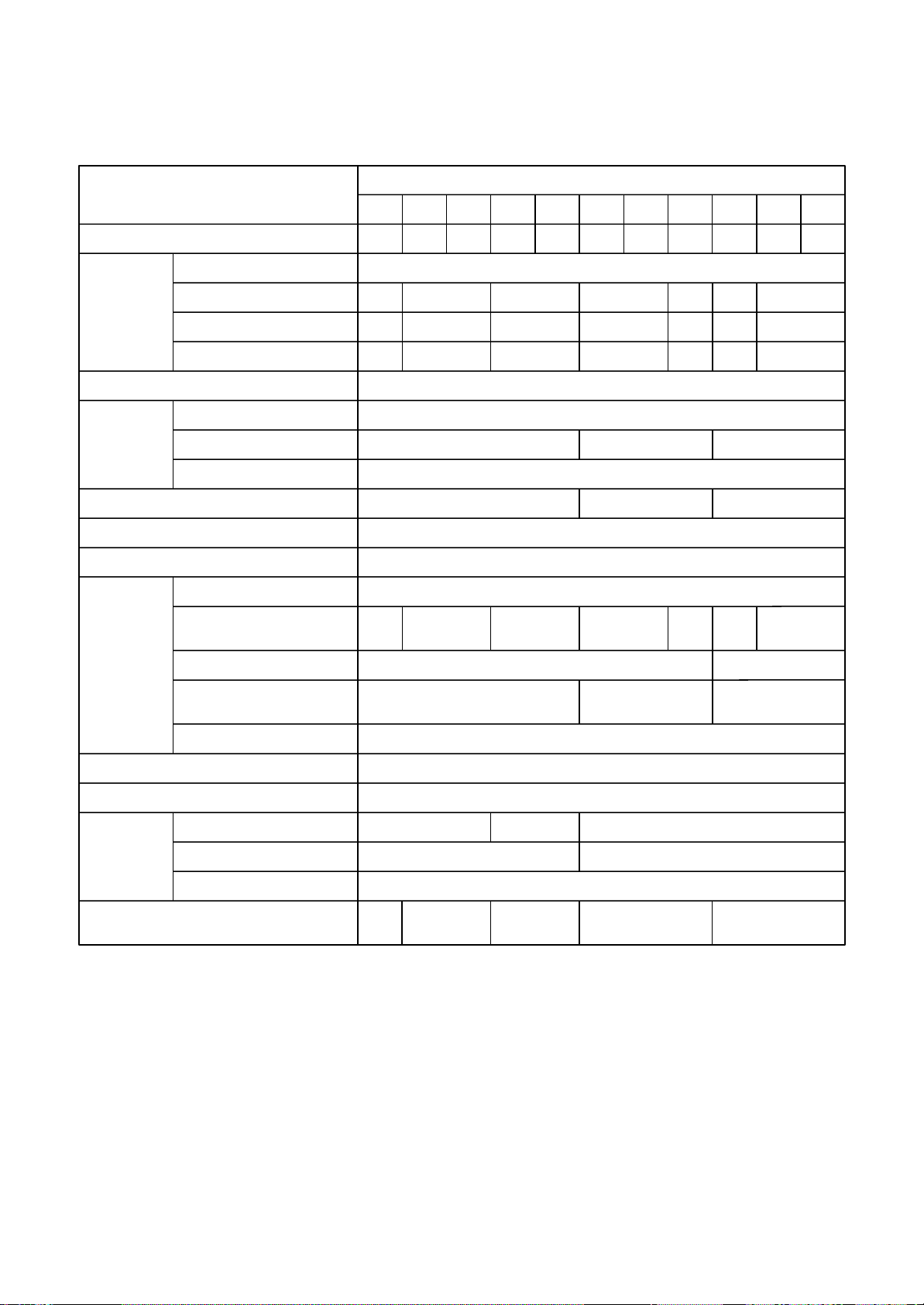
1. SPECIFICATIONS
Model name
(50Hz)
MMD-AP
0076 0096 0126 0156 0186 0246 0276 0306 0366 0486 0566
∗∗∗∗
BHP1-E(TR)
Cooling/Heating capacity
Electrical
Power supply
(Note 1) (kW)
characteristics
Running current (A)
Power consumption (kW)
Starting current (A)
Appearance
Dimension Height (mm)
Width (mm)
Depth (mm)
Total weight (kg)
Heat exchanger
Soundproof / Heat-insulating meterial
Fan unit
Fan
Standard air flow (m³/h)
(Med./Low)
Motor output (W)
External static pressure
(Pa)
(factory setting)
2.2/2.5 2.8/3.2 3.6/4.0 4.5/5.0 5.6/6.3 7.1/8.0 8.0/9.0 9.0/10.0 11.2/12.5 14.0/16.0 16.0/18.0
1phase 50Hz 230V(220V-240V)
0.26 0.29 0.42 0.52
0.038 0.043 0.062 0.077
0.45 0.50 0.73 0.90
0.61 1.07 1.23
0.094 0.172 0.198
1.06 1.85 2.13
Zinc hot dipping steel plate
275
700 1000 1400
750
23 30 40
Finned tube
Polyethlene foam
Centrifugal fan
540
(450/360)
570
(480/390)
800
(660/540)
150
1,200
(990/870)
1,260
(1110/930)
1,920
(1620/1380)
2,100
(1740/1500)
250
30 40 50
30-40-50-65-80-100-120 (7steps)
Remote controller
Standard filter (Long life filter)
Controller
Air filter
Connecting
External static pressure (Pa)
Gas side (mm)
9.5 12.7 15.9
pipe
Liquid side (mm)
Drain port (mm)
Sound pressure level (Note 2)
(High/Med./Low)
(dB(A))
29/26/23
25(Polyvinyl chloride tube)
30/26/23 33/29/25 36/31/27 40/36/33
9.56.4
Note 1 : The cooling capacities and electrical characteristics are measured under the conditions specified by
JIS B 8615 based on the reference piping.
The reference piping consists of 5 m of main piping and 2.5 m of branch piping connected with 0 m
height.
Note 2 : The sound level are measured in an anechoic chamber in accordance with JIS B 8616.
Normally, the values measured in the actual operating environment become larger than the indicated
valves due to the effects of external sound.
Note : Rated conditions Cooling: Indoor air temperature 27˚C DB/19˚C WB, Outdoor air temperature 35˚C DB
Heating: Indoor air temperature 20˚C DB, Outdoor air temperature 7˚C DB/6˚C WB
– 13 –
Model name
(60Hz)
MMD-AP∗∗∗∗BHP1-E(TR)
0076 0096 0126 0156 0186 0246 0276 0306 0366 0486 0566
Cooling/Heating capacity
Electrical
Power supply
(Note 1) (kW)
characteristics
Running current (A)
Power consumption (kW)
Starting current (A)
Appearance
Dimension Height (mm)
Width (mm)
Depth (mm)
Total weight (kg)
Heat exchanger
Soundproof / Heat-insulating meterial
Fan unit
Fan
Standard air flow (m³/h)
(Med./Low)
Motor output (W)
External static pressure
(Pa)
(factory setting)
2.2/2.5 2.8/3.2 3.6/4.0 4.5/5.0 5.6/6.3 7.1/8.0 8.0/9.0 9.0/10.0 11.2/12.5 14.0/16.0 16.0/18.0
1phase 60Hz 220V
0.27 0.31 0.44 0.55
0.038 0.043 0.062 0.077
0.47 0.54 0.76 0.95
0.64 1.12 1.29
0.094 0.172 0.198
1.11 1.94 2.23
Zinc hot dipping steel plate
275
700 1000 1400
750
23 30 40
Finned tube
Polyethlene foam
Centrifugal fan
540
(450/360)
570
(480/390)
800
(660/540)
150
1,200
(990/870)
1,260
(1110/930)
1,920
(1620/1380)
2,100
(1740/1500)
250
30 40 50
30-40-50-65-80-100-120 (7steps)
Remote controller
Standard filter (Long life filter)
Controller
Air filter
Connecting
External static pressure (Pa)
Gas side (mm)
9.5 12.7 15.9
pipe
Liquid side (mm)
Drain port (mm)
Sound pressure level (Note 2)
(High/Med./Low)
(dB(A))
29/26/23
25(Polyvinyl chloride tube)
30/26/23 33/29/25 36/31/27 40/36/33
9.56.4
Note 1 : The cooling capacities and electrical characteristics are measured under the conditions specified by
JIS B 8615 based on the reference piping.
The reference piping consists of 5 m of main piping and 2.5 m of branch piping connected with 0 m
height.
Note 2 : The sound level are measured in an anechoic chamber in accordance with JIS B 8616.
Normally, the values measured in the actual operating environment become larger than the indicated
valves due to the effects of external sound.
Note : Rated conditions Cooling: Indoor air temperature 27˚C DB/19˚C WB, Outdoor air temperature 35˚C DB
Heating: Indoor air temperature 20˚C DB, Outdoor air temperature 7˚C DB/6˚C WB
– 14 –
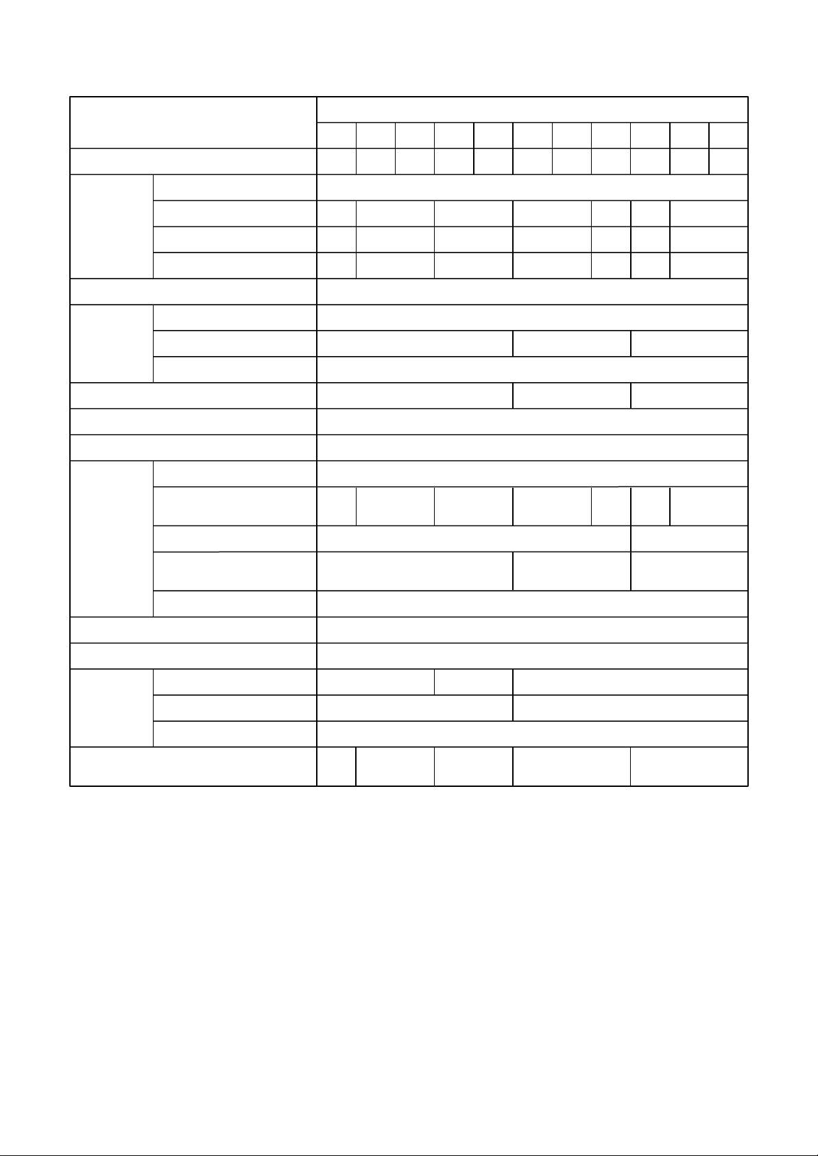
2. AIR DUCTING WORK
AP0076 type AP0096, AP0126 type
Standard air volume: 540 m3/h
External static pressure(Pa)
External static pressure (Pa)
140
120
100
80
60
40
20
Upper limit of
Upper limit of
external static
external static
pessure(120Pa)
pressure (120 Pa)
Low (120 Pa)
Low tap(120Pa)
Standard air volume : 540m3/h
Lower limit of
Lower limit of external static
external static
pressure (120 Pa)
pessure(120Pa)
High tap(120Pa)
High tap(100Pa)
High tap (100 Pa)
High tap (80 Pa)
High tap(80Pa)
High tap (65 Pa)
High tap(65Pa)
High tap (50 Pa)
High tap(50Pa)
High tap(40Pa)
High tap (40 Pa)
High tap (30 Pa)
High tap(30Pa)
Standard filter pressure
Standard filter pressure
loss
loss
High tap (120 Pa)
140
120
100
Low (120 Pa)
Low tap(120Pa)
80
60
External static pressure(Pa)
40
External static pressure (Pa)
20
Upper limit of
Upper limit of
external static
external static
pessure(120Pa)
pressure (120 Pa)
Standard air volume: 570 m3/h
Standard air volume : 570m3/h
Lower limit of
Lower limit of external static
external static
pressure (120 Pa)
pessure(120Pa)
High tap (120 Pa)
High tap(120Pa)
High tap (100 Pa)
High tap(100Pa)
High tap (80 Pa)
High tap(80Pa)
High tap (65 Pa)
High tap(65Pa)
High tap(50Pa)
High tap (50 Pa)
High tap(40Pa)
High tap (40 Pa)
High tap (30 Pa)
High tap(30Pa)
Standard filter
Standard filter
pressure loss
pressure loss
0
200 300 400 500 600 700 800
Air volume(m3/h)
Air Volume (m3/h)
0
200 300 400 500 600 700 800
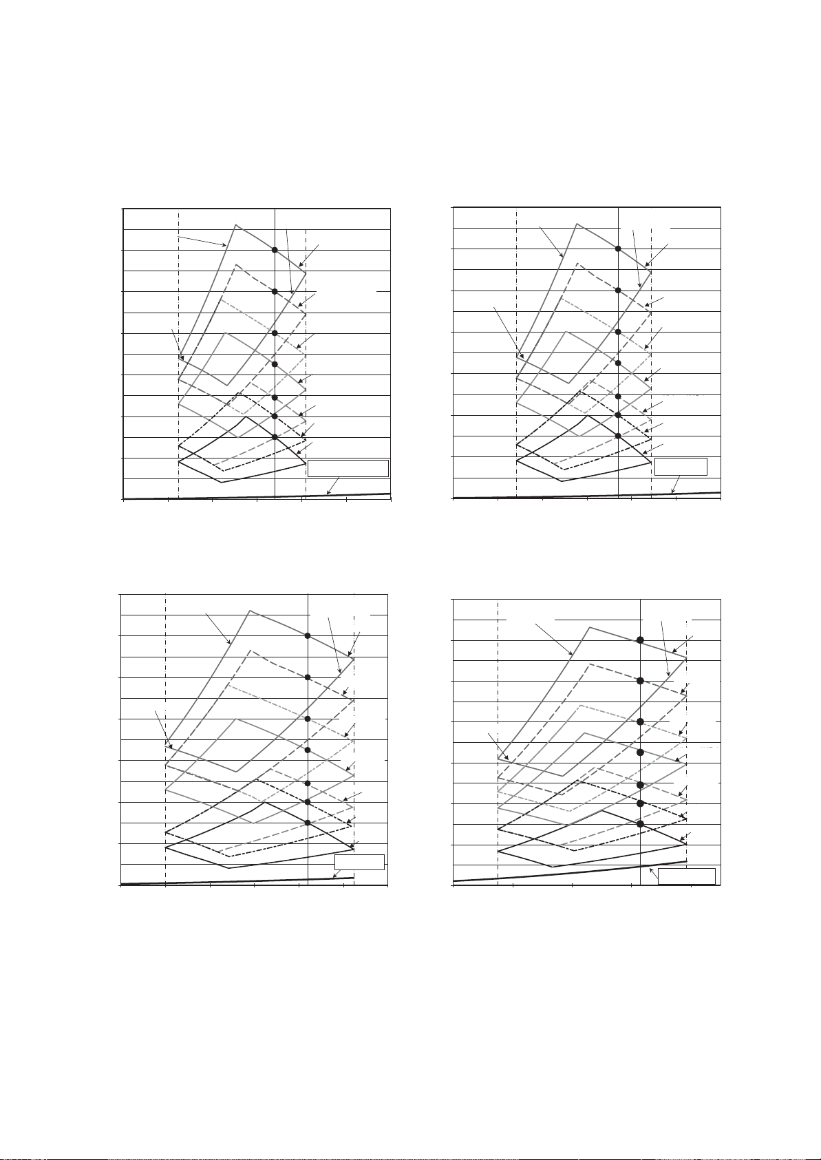
AP0156, AP0186 type AP0246, AP0276 type
Standard air volume : 800m3/h
140
Upper limit of
Upper limit of external
external static
static pressure (120 Pa)
pessure(120Pa)
120
100
Low (120 Pa)
Low tap(120Pa)
80
60
External static pressure(Pa)
40
External static pressure (Pa)
20
0
380480580680780880980
Air Volume (m3/h)
Standard air volume: 800 m3/h
Lower limit of
Lower limit of external
external static
static pressure (120 Pa)
pessure(120Pa)
Air volume(m3/h)
High tap (120 Pa)
High tap(120Pa)
High tap (100 Pa)
High tap(100Pa)
High tap (80 Pa)
High tap(80Pa)
High tap
High tap(65Pa)
(65 Pa)
High tap (50 Pa)
High tap(50Pa)
High tap
High tap
(40 Pa)
a)
(40P
High tap
High tap
(30 Pa)
(30Pa)
Standard filter
Standard filter
pressure loss
pressure loss
140
Upper limit of external
Upper limit of
static pressure
external static
(120 Pa)
pessure(120Pa)
120
100
80
Low tap(120Pa)
Low (120 Pa)
60
40
External static pressure (Pa)
20
0
570 770 970 1170 1370
Air volume(m3/h)
Air Volume (m3/h)
Standard air volume: 1200 m3/h
Air Volume (m3/h)
Lower limit of
Lower limit of external
external static
static pressure
pessure(120Pa)
(120 Pa)
High tap (120 Pa)
High tap(120Pa)
High tap
High tap(100Pa)
(100 Pa)
High tap
High tap(80Pa)
(80 Pa)
High tap
High tap(65Pa)
(65 Pa)
High tap (50 Pa)
H
igh tap(50Pa)
High tap(40Pa)
High tap
(40 Pa)
High tap
High tap(30Pa)
(30 Pa)
Standard filter
Standard filter
pressure loss
pressure loss
– 15 –

AP0306 type AP0366 type
Standard air volume: 1260 m3/h
140
120
Upper limit of
Upper limit of
external static
external static
pressure (120 Pa)
pessure(120Pa)
Standard air volume : 1260m3/h
Lower limit of
Lower limit of
external static
external static
pressure (120 Pa)
pessure(120Pa)
100
80
Low (120 Pa)
Low tap(120Pa)
60
External static pressure(Pa)
40
External static pressure (Pa)
20
0
630 830 1030 1230 143 0
High tap (120 Pa)
High tap(120Pa)
High tap
High tap
(100 Pa)
(100Pa)
High tap
(80 Pa)
High tap(80Pa)
High tap
High tap
(65Pa)
(65 Pa)
High tap (50 Pa)
High tap(50Pa)
High tap
High tap
(40 Pa)
(40Pa)
High tap
High tap(30Pa)
(30 Pa)
Standard filter
Standard filter
pressure loss
pressure loss
140
Upper limit of
Upper limit of
external static
external static
pessure(120Pa)
pressure (120 Pa)
120
100
Low tap(120Pa)
Low (120 Pa)
80
60
External static pressure(Pa)
40
External static pressure (Pa)
20
0
900 1100 1300 1 500 1700 1900 2100 2300 2500
Air volume(m3/h)
Air Volume (m3/h)
AP0486, AP0566 type
Standard air volume: 2100 m3/h
140
120
Upper limit of
Upper limit of
external static
external static
pressure (120 Pa)
pessure(120Pa)
Standard air volume : 2100m3/h
Lower limit of
Lower limit of
external static
external static
pessure(120Pa)
pressure (120 Pa)
High tap (120 Pa)
High tap(120Pa)
Standard air volume: 1920 m3/h
Standard air volume : 1920m3/h
Lower limit of
Lower limit of external static
external static
pressure (120 Pa)
pessure(120Pa)
High tap (120 Pa)
High tap(120Pa)
High tap (100 Pa)
High tap(100Pa)
High tap (80 Pa)
High tap(80Pa)
High tap (65 Pa)
High tap(65Pa)
High tap (50 Pa)
High tap(50Pa)
High tap (40 Pa)
High tap(40Pa)
High tap (30 Pa)
High tap(30Pa)
Standard filter
Standard filter
pressure loss
pressure loss
Air volume(m3/h)
Air Volume (m3/h)
100
Low tap(120Pa)
Low (120 Pa)
80
60
External static pressure(Pa)
40
External static pressure (Pa)
Standard filter
Standard filter
20
pressure loss
pressure loss
0
1000 1200 1400 1600 1800 2000 2200 2400 2600
Air volume(m3/h)
Air Volume (m3/h)
High tap(100Pa)
High tap (100 Pa)
High tap (80 Pa)
High tap(80Pa)
High tap (65 Pa)
High tap(65Pa)
High tap(50Pa)
High tap(40Pa)
High tap
(50 Pa)
High tap
(40 Pa)
High tap
High tap
(30Pa)
(30 Pa)
– 16 –
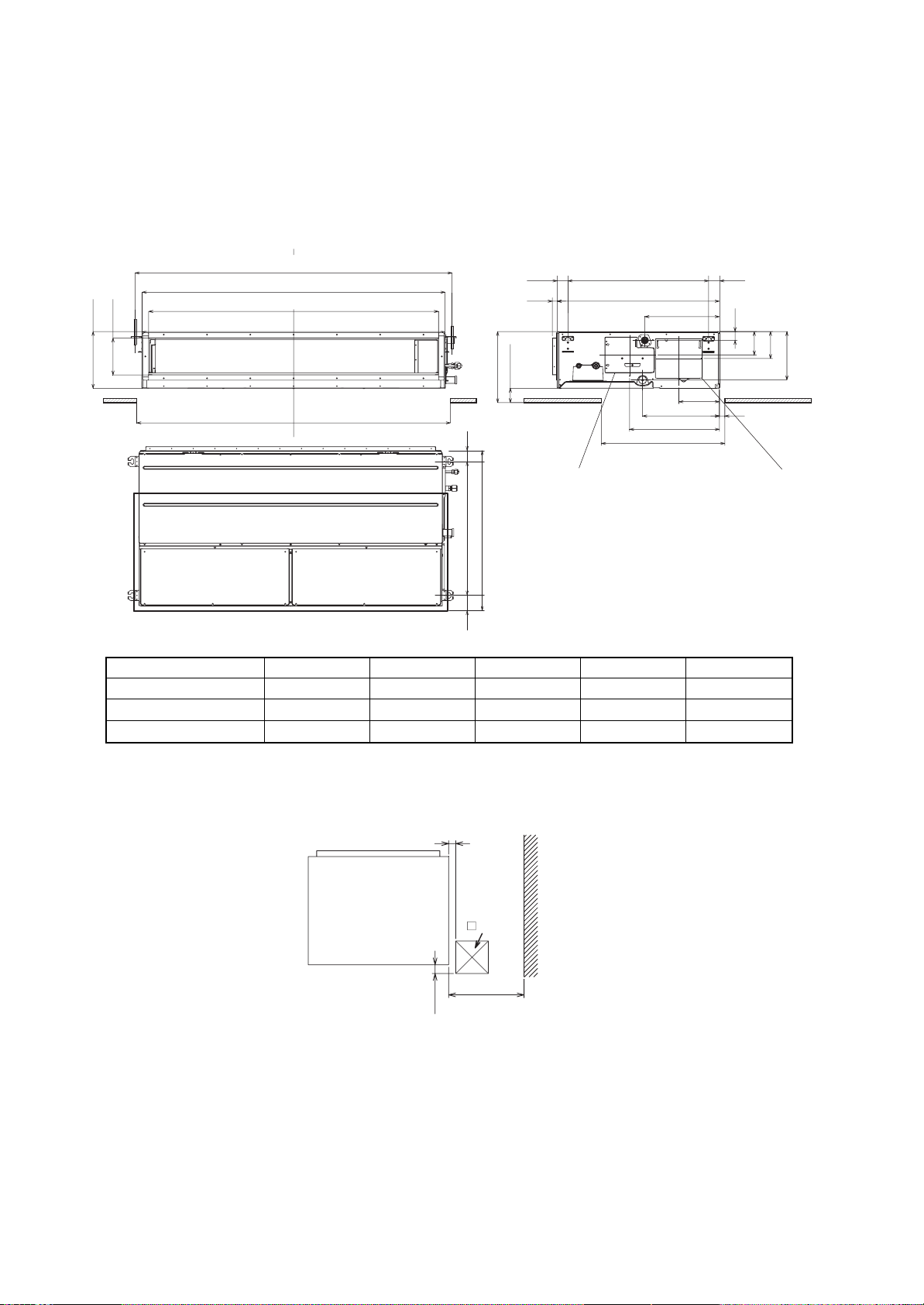
3. CONSTRUCTION VIEWS (EXTERNAL VIEWS)
MMD-AP0076BHP1*, AP0096BHP1*, AP0126BHP1*, AP0156BHP1*, AP0186BHP1*
AP0246BHP1*, AP0276BHP1*, AP0306BHP1*, AP0366BHP1*, AP0486BHP1*, AP0566BHP1*
C
L
Hanging bolt pitch
650
750
345
187.5
355
415
570
275
180
Hanging bolt pitch B
Main unit dimension A
External dimensions of flange C
D
70 or more
345 or more
Drain pan / Drain
pump check cover
750
650 5050
50 50
22
∗
∗
∗
∗
43
113.5
131
236
25
Electrical
control box
Dimension
AP007 ~ 018 type
AP024 ~ 030 type
AP036 ~ 056 type
ABCD
700 765 640 750
1000 1065 940 1050 500
1400 1465 1340 1450 700
Air discharge
100 or more
Check port
450
120
E
Service space
(E for maintenance of air filter)
E
700
– 17 –
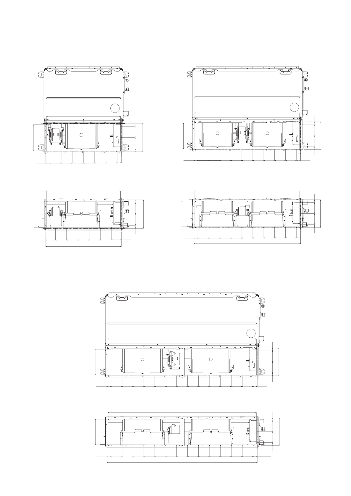
AP007 ~ AP018 type
AP024 ~ AP030 type
<Under air intake>
235.4
37.5
<Back air intake>
235.2
659.4
660
<Under air intake>
959.4
37.5
27
254
100 100
27
27
254
100 100
27
37.5
100
100
100100100100
235.4
37.5
100100
100100
100100100100100
<Back air intake>
960
27
100100
254
235.2
2727
100100
254
87.5
100
100100
675
27
100100
87.5
AP036 ~ AP056 type
<Under air intake>
235.4
37.5
100
<Back air intake>
100100100
975
100
100100
254
100 100
27 27
37.5
37.5
1359.4
100
100
100100100
100
100100
100
100100100100
100100
37.5
235.2
37.5
100
100
100
1360
100100100
100
1375
– 18 –
2727
100100
254
100
100100100100100
37.5
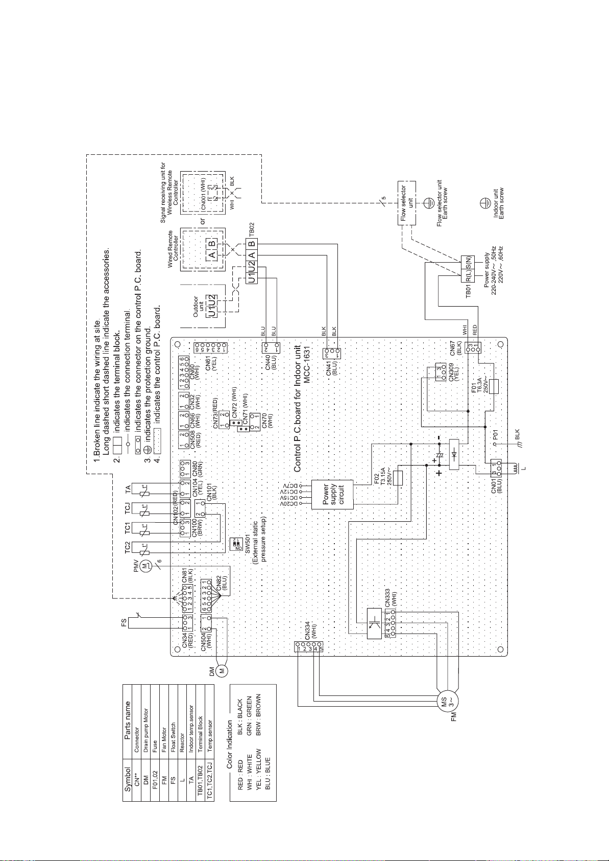
4. WIRING DIAGRAMS
Models : MMD-AP0076BHP1*, AP0096BHP1*, AP0126BHP1*, AP0156BHP1*,
AP0186BHP1*, AP0246BHP1*, AP0276BHP1*, AP0306BHP1*,
AP0366BHP1*, AP0486BHP1*, AP0566BHP1*
– 19 –

5. PARTS RATING
Model
Fan motor
Drain pump motor
Float switch
Pulse motor
Pulse motor valve
TA sensor
TC1 sensor
TC2 sensor
TCJ sensor
Model
Fan motor
Drain pump motor
Float switch
Pulse motor
Pulse motor valve
TA sensor
TC1 sensor
TC2 sensor
TCJ sensor
MMD-AP
MMD-AP
0076BHP1 0096BHP1 0126BHP1 0156BHP1 0186BHP1
ICF-340W150-2
MDP-1401
FS-1A-31-3
EFM-MD12TF-1
EFM-25YGTCTH-2 EFM-40YGTF-1
Lead wire length: 218 mm
Ø4 size lead wire length: 1000 mm Vinyl tube (Blue)
Ø6 size lead wire length: 1000 mm Vinyl tube (Black)
Ø6 size lead wire length: 1000 mm Vinyl tube (Red)
0246BHP1
0276BHP1 0306BHP1 0366BHP1 0486BHP1
340W150-1 340W250-1
EFM-40YGTF-1 EFM-60YGTCTH-1
Ø4 size lead wire length: 1000 mm Vinyl tube (Blue)
Ø6 size lead wire length: 1000 mm Vinyl tube (Black)
Ø6 size lead wire length: 1000 mm Vinyl tube (Red)
MDP-1401
FS-1A-31-3
EFM-MD12TF-1
Lead wire length: 218 mm
0566BHP1
– 20 –
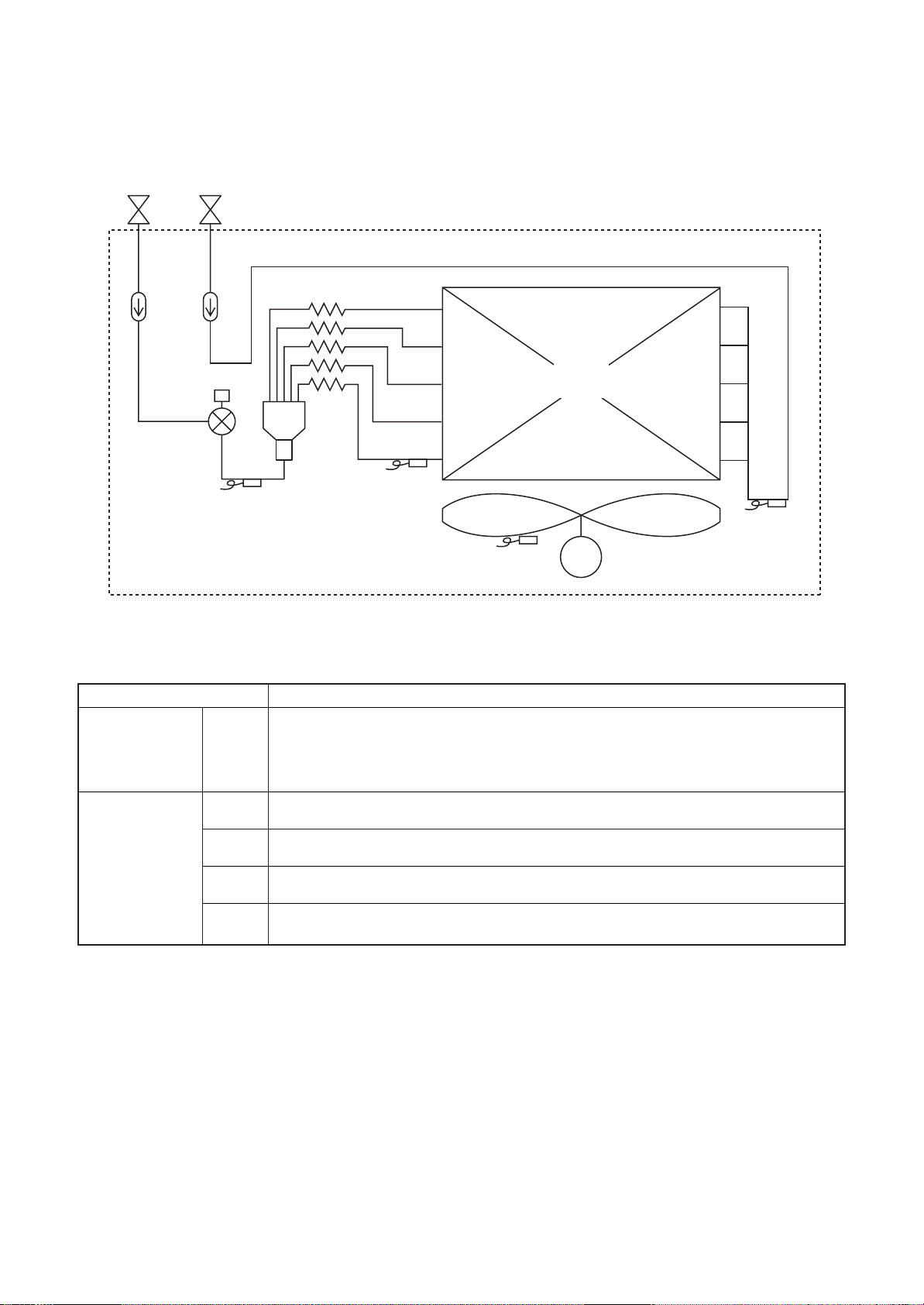
6. REFRIGERANT CYCLE DIAGRAM
Indoor unit
Gas sideLiquid side
Strainer
Pulse Motor
Valve (PMV)
Sensor
(TC2)
Capillary tube
Strainer
Sensor
(TCJ)
Explanation of functional parts in indoor unit
Functional part name
Pulse Motor Valve
PMV
Temp. Sensor (Connector CN104 (2P): Yellow)
1.TA
2.TC1
3.TC2
4.TCJ
(Connector CN082 (6P): Blue)
1) Controls super heat in cooling operation
2) Controls under cool in heating operation
3) Recovers refrigerant oil in cooling operation
4) Recovers refrigerant oil in heating operation
1) Detects indoor suction temperature
(Connector CN100 (3P):
1) Controls PMV super heat in cooling operation
(Connector CN101 (2P): Black)
1) Controls PMV under cool in heating operation
(Connector CN102 (2P): Red)
1) Controls PMV super heat in cooling operation
Brown)
Heat exchanger
at indoor side
Fan
Sensor
(TA)
Functional outline
M
Sensor
(TC1)
Fan motor
– 21 –
7. CONTROL OUTLINE
Indoor unit
Control specifications
NO.
1
2
3
Item Specification outline Remarks
Upon power
supply reset
1. Identification of outdoor unit
When the power supply is reset, the outdoor unit is identified, and control
is redirected according to the identification result.
2. Indoor fan speed and air flow direction control availability settings
Settings such as indoor fan speed and air flow direction control availability
are replaced on the basis of EEPROM data.
3. If power supply reset is performed in the wake of a fault, the check code
is cleared.
If the abnormality persists after the Start / Stop button on the remote
controller is pressed to resume operation, the check code is redisplayed
on the remote controller.
Operation
selection
Room temp.
control
1. The operation mode changes in response to an operation selection
command issued via the remote controller.
Remote controller command Control outline
STOP Air conditioner shutdown
FAN Fan operation
COOL Cooling operation
DRY Drying operation
HEAT Heating operation
1. Adjustment range - remote controller temperature setting (°C)
COOL / DRY HEAT
Wired type 18~29 18~29
Wireless type 18~30 16~30
2. In heating operation, the temperature setting may be fine-tuned via the
Ts: Temperature
Ta: Room
Shift in heating
suction
temperature
(not applicable to
remote controller
thermo
operation)
DN code “06”.
SET DATA 0 2 4 6
Temperature setting adjustment +0 ˚C +2 ˚C +4 ˚C +6 ˚C
setting
temperature
Automatic
capacity control
4
Factory default
Model type SET DATA
Floor standing (standard, concealed, cabinet) 0
Other model 2
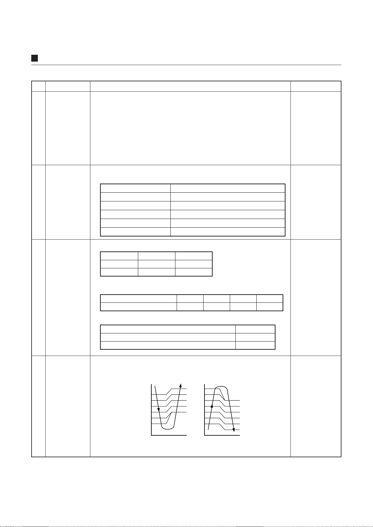
1. The outdoor unit determines the operational capacities of indoor units
according to the difference between Ta and Ts.
Cooling Heating
Ta
(˚C)
+2
+1
Ts
–1
SD
SB
S9
S7
S5
S3
S0
Ta
(˚C)
+1
Ts
–1
–2
S3
S5
S7
S9
SB
SD
SF
S0
Ts: Temperature
setting
Ta: Room
temperature
– 22 –
NO. Item Specification outline Remarks
Fan speed
control
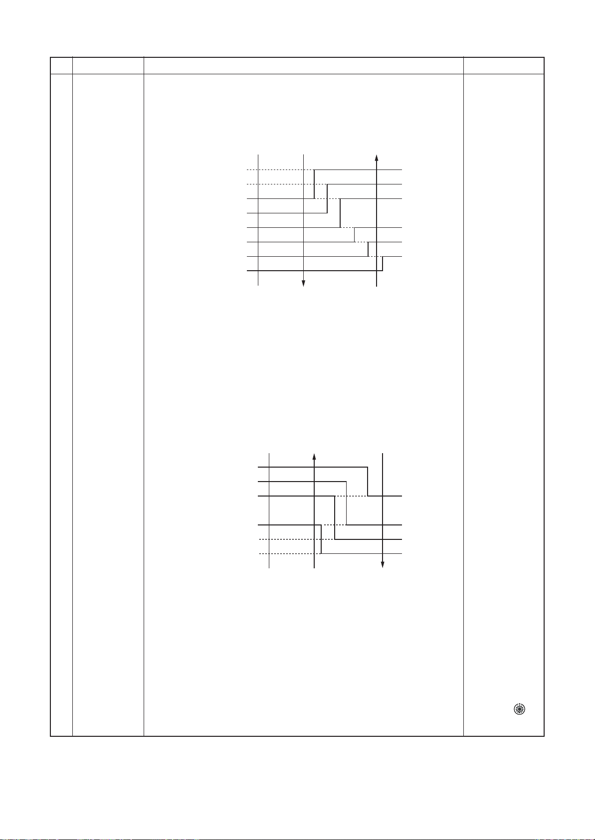
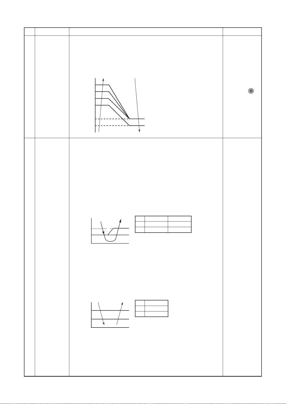
1. The fan operates in one of the four speed modes of “HIGH (HH)”, “MED
(H)”, “LOW (L)” and “AUTO” on the basis of a command issued via the
remote controller. (Concealed duct high static pressure type: HH only)
2. In AUTO fan speed mode, the air speed changes according to the
difference between Ta and Ts.
<Cooling>
Ta (˚C)
+3.0
+2.5
+2.0
+1.5
+1.0
+0.5
Tsc
–0.5
HH <HH>
H+ <HH>
H <HH>
L+ <H+>
L <H>
L <H>
L <L+>
A
B
C
D
E
F
G
HH > H+ > H >
L+ > L > UL
or LL
• Control is identical in remote controller thermo and body thermo
operation.
Speed modes shown in < > apply to cooling operation under AUTO air
conditioner operation mode.
• In AUTO fan speed mode, the fan speed remains the same for 3 minutes
each time a speed change occurs.
5
However, a speed change command issued via the remote controller can
override this, and the fan speed changes accordingly.
• At the beginning of cooling operation, a higher speed (steeper downward
temperature gradient) is chosen.
• As long as the temperature difference remains on a boundary line, the
fan speed stays the same.
<Heating>
Ta (˚C)
(–0.5) –1.0
(0) Tsh
(+0.5) +1.0
(+1.0) +2.0
(+1.5) +3.0
(+2.0) +4.0
Figures inside ( ) applies to remote controller thermo operation.
Figures outside ( ) applies to body thermo operation.
Speed modes shown in < > apply to heating operation under AUTO air
conditioner operation mode.
• In AUTO fan speed mode, the fan speed remains the same for 1 minute
each time a speed change occurs.
However, a speed change command issued via the remote controller can
override this, and the fan speed changes accordingly.
• At the beginning of heating operation, a higher speed (steeper upward
temperature gradient) is chosen.
• As long as the temperature difference remains on a boundary line, the
fan speed stays the same.
• When TC2 ≥ 60 °C, the fan speed is raised by one step.
3. If the air conditioner goes thermo OFF during heating operation, the fan
speed drops down to LL (breeze).
L <L+>
L+ <H>
H <H+>
H+
<HH>
HH
<HH>
E
D
C
B
A
DN code “32”
“0000”: Body
thermo
“0001”: Remote
controller thermo
TC2: Indoor heat
exchanger sensor
temperature
“HEATING
STANDBY
displayed
”
– 23 –
NO. Item Specification outline Remarks
Cold air
discharge
prevention
control
1. In heating operation, the upper limit of the fan tap is set according to the
lower of whichever is the higher between TC2 sensor and TCJ sensor
temperatures, on the one hand, and TC1 sensor temperature, on the
other.
• If the fan continuously operates in zone B for 6 minutes, it automatically
moves into zone C.
• During defrosting, the control point is shifted by +6 °C.
TCJ: Indoor heat
exchanger
sensor
temperature
• In zones D and E,
priority is given
to the remote
controller fan
6
32
30
28
D
C
E
26
20
16
˚C
A zone: OFF
B zone: 26˚C or above and
C zone: 28˚C or above and
D zone: 30˚C or above and
B
E zone: High
A
below 28˚C
breeze
below 30˚C
Low
below 32˚C
Medium
speed setting.
•In zone A,
“HEATING
STANDBY
is displayed.
”
Freeze
prevention
control (low
temp. release)
7
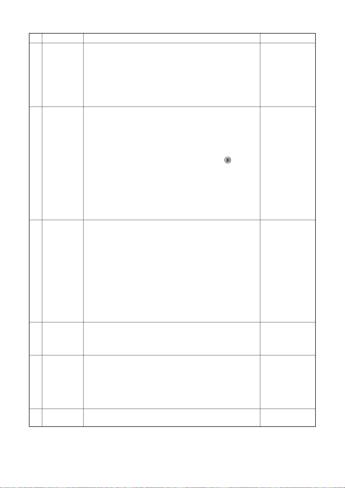
1. During cooling, the air conditioner is operated in the manner described
below according to the temperature readings of the TC1, TC2 and TCJ
sensors.
• If zone J operation is detected for 5 minutes, the air conditioner is forced
into thermo OFF.
• In zone K, the timer is put on pause, with the current timer count
retained.
• If zone I operation is detected, the timer count is cleared, and the air
conditioner returns to normal operation.
• If continuous zone J operation forces the air conditioner into thermo OFF,
the indoor fan is operated in breeze mode until it moves into zone I.
The control is terminated under the following conditions:
Termination conditions
1) TC1 ≥ 12 °C, TC2 ≥ 12 °C, and TCJ ≥ 12 °C
(˚C)
P1
Q1
P1
I
K
J
a
Q1
TC1
10˚C (5˚C)
0˚C
TC2, TCJ
–10˚C
–14˚C
2) Passage of 20 minutes after stoppage
2. During cooling, the air conditioner is operated in the manner described
below according to the temperature readings of the TC2 and TCJ sensors.
• If zone M operation is detected for 45 minutes, the air conditioner is
forced into thermo OFF.
• In zone N, the timer is put on pause, with the current timer count
retained.
• When the air conditioner goes back into zone M, timer count is resumed
from the retained value.
TC1:
Indoor heat
exchanger
sensor
temperature
(˚C)
P2
Q2
L
N
M
P2
Q2
TC2, TCJ
5
–2.0
• If zone L operation is detected, the timer count is cleared, and the air
conditioner returns to normal operation.
Reset conditions
1) TC1 ≥ 12 °C, TC2 ≥ 12 °C and TCJ ≥ 12 °C
2) Passage of 20 minutes after stoppage
– 24 –
* With models
without TC2,
TC2 is not
part of the
control
parameters.
NO. Item Specification outline Remarks
Cooling oil
(refrigerant)
recovery control
8
Heating
refrigerant (oil)
recovery
control
9
While the outdoor unit is recovering cooling oil (refrigerant), the indoor
units perform the following control tasks:
[common for operational (cooling thermo ON / thermo OFF / FAN), as
well as nonoperational indoor units]
1) Open the indoor PMV to a certain degree.
2) Engage in recovery control for a specified period of time and return
to normal cooling operation at the end of this period upon
terminating the control.
3) Operate the drain pump throughout the recovery control period and
for about 1 minute after it.
While the outdoor unit is recovering heating refrigerant (oil), the indoor
units perform the following control tasks:
1) Open the indoor PMV to a certain degree.
2) Control the indoor fan according to the operation mode.
[Indoor units operating in heating thermo ON / OFF state]
Let the indoor fan continue operating, but turn it off if the temperature
of the indoor heat exchanger drops.
[Indoor units operating in FAN mode]
Turn off the indoor fan and display “HEATING STANDBY
remote controller.
[Non-operational indoor units]
Keep the indoor fan turned off.
3) Terminate the recovery operation depending on the TC2
temperature reading.
The timing of termination is determined by each indoor unit.
4) Operate the indoor fan and drain pump for about 1 minute after the
termination of the recovery operation. (Applicable to compact 4-way
cassette type and 1- way cassette type)
” on the
• Recovery operation
normally takes
place roughly every
2 hours.
• The opening
position of the
indoor PMV
depending on the
type and capacity
of the indoor unit.
• Recovery
operation
normally takes
place roughly
every hour.
• The opening
position of the
indoor PMV
depending on the
type and capacity
of the indoor unit.
Defrosting
control
10
Short
intermittent
operation
11
compensation
control
Drain pump
control
12
While the outdoor unit is engaged in defrosting control, the indoor units
perform the following control tasks:
1) Open the indoor PMV to a certain degree.
2) Control the indoor fan according to the operation mode.
[Indoor units operating in heating thermo ON / OFF state]
Let the indoor fan continue operating for a while, but turn it off as the
temperature of the indoor heat exchanger drops.
[Indoor units operating in FAN mode]
Let the indoor fan continue operating.
[Non-operational indoor units]
Keep the indoor fan turned off.
3) As defrosting control comes to an end, it gives way to heating
refrigerant (oil) recovery control.
(For control details, see “9. Heating refrigerant (oil) recovery control” above.)
1. For 5 minutes after startup, the system is forced to continue operating
even if it reaches the thermo OFF region.
2. However, priority is given to cooling / heating selection, operation
standby, and protective control, so that there is no overriding of
thermo OFF in these cases.
1. During cooling (including DRY operation), the drain pump is operated
at all times.
2. If the float switch is activated while the drain pump is in operation, the
drain pump continues operating, with the relevant check code displayed.
3. If the float switch is activated while the drain pump is turned off, thermo
OFF is forced on the air conditioner, with the drain pump put into
operation. If the float switch continues to be activated for about 5 minutes,
the drain pump is turned off, with the relevant check code displayed.
• For defrosting
commencement
conditions, see 5
Control Outline “10.
Defrosting control
(reverse defrosting
method)” in SMMS-i
Outdoor Unit
Service Manual
A10-005 above.
• The opening
position of the
indoor PMV
depending on the
type and capacity
of the indoor unit.
Check code [P10]
Elimination of
13
residual heat
1. When the air conditioner is turned off after engaging in heating operation,
the indoor fan is operated for about 30 seconds in “breeze” mode.
– 25 –
NO. Item Specification outline Remarks
Filter sign
display
(not applicable
to wireless type)
*Provided in
14
the separately
mounted type,
TCB-AX21E.
Operation
standby
Heating standby
15
1. The indoor fan’s cumulative hours of operation are counted, and when
these exceed the prescribed value (2500H), a filter replacement signal
is sent to the remote controller to display a filter sign on it.
2. When a filter reset signal is received from the remote controller, the
timer measuring cumulative hours is cleared. If the prescribed hours
have been exceeded, the hours count is reset, with the sign on the
remote controller display erased.
2500HFilter service life
<Operation standby> .......... Displayed on remote controller
1. When any of the DN codes listed below is displayed
• “P05” - Detection of an open phase in the power supply wiring
• “P10” - Detection of indoor flooding in at least one indoor unit
• “L30” - Detection of an interlock alarm in at least one indoor unit
2. Forced thermo OFF
• “COOL / DRY” operation is unavailable because at least one indoor
unit is operating in “HEAT” mode.
• “HEAT” operation is unavailable because at least one indoor unit is
operating in
“COOL / DRY” mode under priority cooling setting (bit 1 of SW11 on
outdoor I/ F P.C. board ON).
3. All indoor units not able to engage in any of the above operations
stand by in thermo OFF state.
4. The indoor fan has been turned off because the system is engaged in
a heat refrigerant (oil) recovery operation.
<Heating standby> .......... Displayed on remote controller
1. Normal thermo OFF
• During heating, the indoor unit goes thermo OFF as the heating
temperature setting is reached.
2. During heating, the fan rotates at a breeze speed (UL or lower) or
remains stationary to prevent cold air from being discharged
(including defrosting operation).
3.Forced thermo OFF
• “HEAT” operation is unavailable because at least one indoor unit is
operating in
“COOL / DRY” mode under priority cooling setting (bit 1 of SW11 on
outdoor I/ F P.C. board ON).
“FILTER
” displayed
• “OPERATION
STANDBY
displayed
No display
provided on
wireless remote
controller
• “HEATING
STANDBY
displayed
”
”
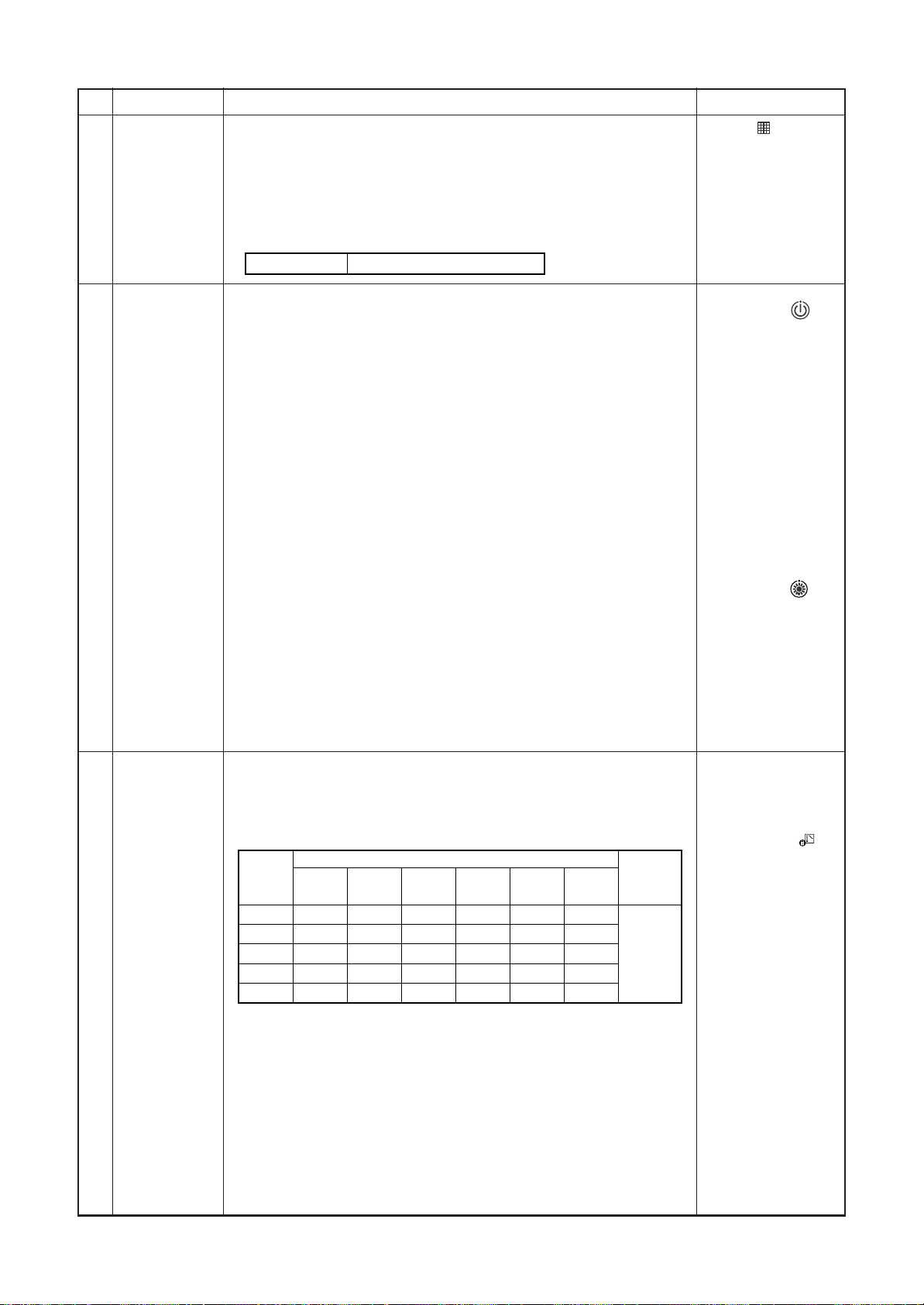
Selection of
central control
mode
16
1. The range of operations that can be performed via an indoor unit
remote controller can be determined through the setting of the central
controller.
2. Setting details
TCC-Link central control
Operation
via TCCLink
Individual
Central 1
Central 2
Central 3
Central 4
(
{
Start / stop
central
control
selection
{
×
×
{
: Accessible × : Inaccessible)
{
Operation on RBC-AMT32E
Operation
mode
selection
Timer
setting
{
{
×
×
×
{
×
×
{
{
Temperature
setting
{
{
×
×
{
Fan speed
setting
{
{
{
{
{
Air flow
direction
setting
{
{
{
{
{
RBC-
AMT32E
display
“CENTRAL
CONTROL
PROGRESS”
• In the case of a
wired remote
controller,
“CENTRAL
CONTROL IN
PROGRESS
”
is displayed (lit up)
while in central
control mode.
• The display blinks
when a control
function
IN
inaccessible to a
remote controller is
chosen.
• A wireless remote
controller has the
same set of control
functions, although
there is no display.
When a control
operation is
performed via a
wireless remote
controller while in
central control
mode, a peep
sound alert (5
times) is provided.
– 26 –
NO. Item Specification outline Remarks
DC motor 1) When the fan operation has started, positioning of the stator and the
rotor are performed.
(Moves slightly with tap sound)
2) The motor operates according to the command from the indoor
controller.
17
Notes)
• When the fan rotates while the air conditioner stops due to entering of
outside air, etc, the air conditioner may operate while the fan motor
stops.
• When a fan lock is found, the air conditioner stops, and an error is
displayed.
• If static pressure of the used duct does not match with the setup value of
static pressure, which was decided in the static pressure setting code No.
[5D], the air conditioner may stop or an error code may be displayed.
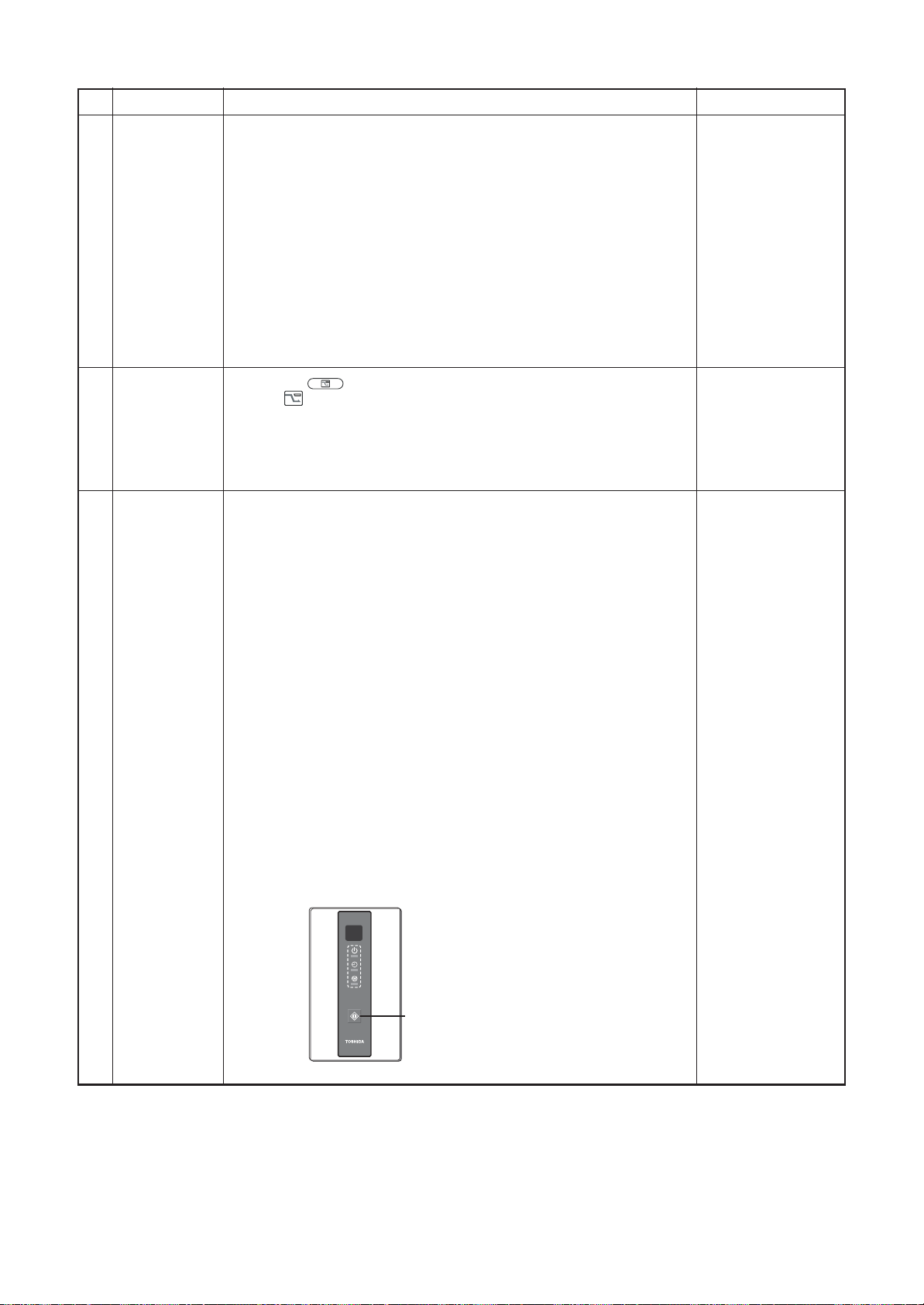
SAVE
Power saving
mode
1. Push the
2. The “
button on the remote controller
“ segment lights up on the wired remote controller display.
3. The requirement capacity ratio is limited to approximately 75 %.
18
4. If the power saving operation is enabled, the settings are retained
when the operation is stopped, when the mode is changed, or when
the power is reset. The power saving operation will be enabled the
next time the operation starts.
Frequency
fixed
operation
(Test run)
<In case of wired remote controller>
1) When pushing [CHK] button for 4 seconds or more, [TEST] is displayed
on the display screen and the mode enters in Test run mode.
2) Push [ON/OFF] button.
3) Using [MODE] button, set the mode to [COOL] or [HEAT].
• Do not use other mode than [COOL]/[HEAT] mode.
• During test run operation, the temperature cannot be adjusted.
• An error is detected as usual.
• A frequency fixed operation is performed.
4) After the test run, push [ON/OFF] button to stop the operation.
(Display in the display part is same as the procedure in Item 1.)
5) Push [CHK] button to clear the test run mode.
([TEST] display in the display part disappears and the status returns
to the normal stop status.)
Check code “P12”
The power saving
operation cannot be
set by the wireless
remote controller or
wired remote
controller of
AMT31E or older.
Command frequency
is approximately [S7]
19
<In case of wireless remote controller>
1) When TEMPORARY button is pushed for 10 seconds or more, “Pi!”
sound is heard and the operation changes to test run. After approx. 3
minutes, a cooling operation starts forcedly.
Check cool air starts blowing. If the operation does not start, check
wiring again.
2) To stop a test operation, push TEMPORARY button once again
(Approx. 1 second).
Check wiring / piping of the indoor and outdoor units in test run.
TEMPORARY button
– 27 –
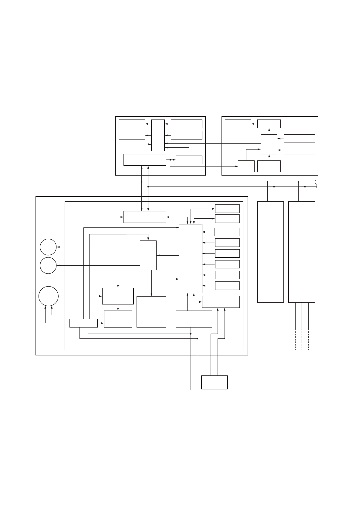
8. APPLIED CONTROL AND FUNCTIONS
Wired (Simple) heder remote controller (Max. 2 units) Schedule remote controller
Outdoor unit
Outdoor unit
NU1U2
U1 U2
L
321
Up to 8 units are connectable.
∗1 It is unavailable to connect the Schedule remote
controller to the simple wired remote controller.
Same as left
#3
(Follower)
A B
AB
Same as left
#2
(Follower)
A B
DC5V
DC5V
Indoor unit
#1 (Heder)
Indoor control P.C. board (MCC-1631)
Drain
pump
PMV
Indoor
fan motor
CPU
H8/36109
Driver
DC12V
DC5V
DC20V
External
output
Remote controller
communication circuit
Display LCD Function setup
Key switch
CN2
CN1
∗1
CPU
Display LED
Display LCD LCD driver
CPU
Remote controller
communication circuit
Function setup
Key switch
Power circuit
Power circuit
DC280V
Fan motor
control circuit
CPU
TMP88CH47FG
(TMP88PH47FG)
EEPROM1
EEPROM2
TA sensor
TC1 sensor
TC2 sensor
TCJ sensor
Float input
HA
Run
Alarm
Defrost
Thermo. ON
COOL
HEAT
FAN
BUS
comunication circuit
AC
synchronous
signal input circuit
Power supply
1
∅
, 220-240V, 50Hz
1
∅
, 220V, 60Hz
Powe r
circuit
Secondary
battery
Outdoor unit
321
(INCLUDING CIRCUIT CONFIGURATION)
8-1. Indoor controller block diagram
8-1-1. In Case of Connection of Wired (Simple) Remote Controller
<Concealed Duct Standard type>
– 28 –
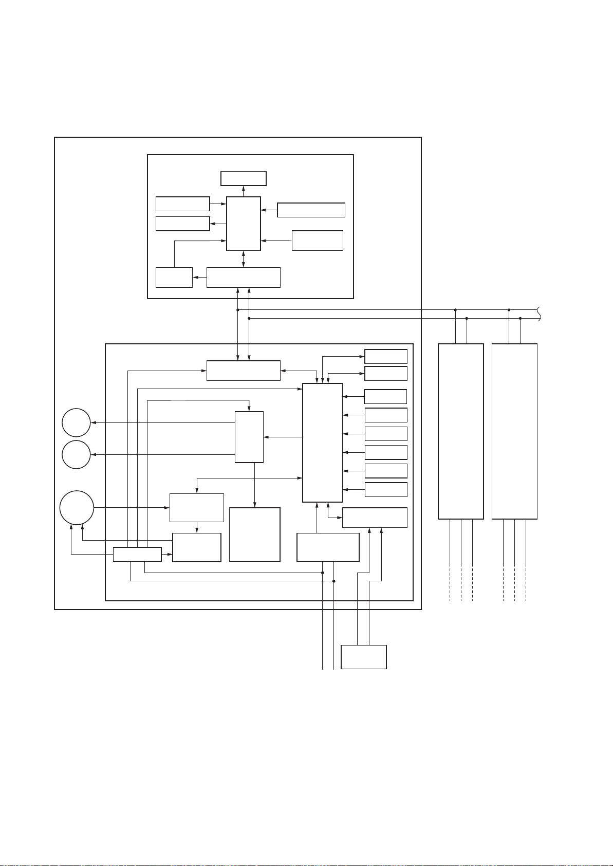
8-1-2. In Case of Connection of Wireless Remote Controller
<Concealed Duct Standard type>
Indoor unit
#1 (Heder)
Wireless remote controller
Receiver P.C. board
Display LED
Drain
pump
PMV
Indoor
fan motor
DC280V
Receive circuit
Buzzer
DC5V
Powe r
circuit
Indoor control P.C. board (MCC-1631)
DC20V
DC5V
DC12V
TMP88CH47FG
(TVP88PH47FG)
Fan motor
Power circuit
control circuit
Remote controller
communication circuit
Remote controller
communication circuit
CPU
CPU
AB
Driver
External
output
Run
Alarm
Defrost
Thermo. ON
COOL
HEAT
FAN
Function setup SW
Temporary
operation SW
CPU
H8/36109
AC
synchronous
signal input circuit
EEPROM2
EEPROM1
TA sensor
TC1 sensor
TC2 sensor
TCJ sensor
Float input
HA
BUS
comunication circuit
#2
(Follower)
A B
Same as left
#3
(Follower)
A B
Same as left
321
321
L
Power supply
∅
, 220-240V, 50Hz
1
∅
, 220V, 60Hz
1
– 29 –
NU1U2
U1 U2
Outdoor unit
Outdoor unit
Up to 8 units are connectable.
Outdoor unit

8-1-3. Connection of Both Wired (Simple) Remote Controller and Wireless Remote Controller
<Concealed Duct Standard type>
Indoor unit
#1 (Heder)
Receive
circuit
Buzzer
DC5V
Powe r
circuit
Display LED
CPU
Remote controller
communication circuit
Receiver P.C. board
Function setup SW
Temporary
operation SW
Wired (Simple) heder remote controller
communication circuit
(Max. 2 units)
Display
LCD
Display
LED
Remote controller
ABAB
CPU
Function
setup
Key
switch
DC5V
Powe r
circuit
CN2
CN1
∗1
Schedule remote controllerWireless remote controller
Display
LCD
DC5V
Powe r
circuit
LCD
driver
CPU
Function
setup
Key
switch
Secondary
battery
Drain
pump
PMV
Indoor
fan motor
DC280V
Indoor control P.C. board (MCC-1631)
Power circuit
DC20V
DC5V
DC12V
TVP88CH47FG
(TMP88PH47FG)
control circuit
Remote controller
communication circuit
CPU
Fan motor
AB
Driver
External
output
Run
Alarm
Defrost
Thermo. ON
COOL
HEAT
FAN
CPU
H8/36109
comunication circuit
AC
synchronous
signal input circuit
NU1U2
L
Outdoor unit
#2
(Follower)
A B
EEPROM2
EEPROM1
TA sensor
TC1 sensor
TC2 sensor
TCJ sensor
Float input
HA
BUS
Up to 8 units are connectable.
∗1 It is unavailable to connect the Schedule remote
U1 U2
controller to the simple wired remote controller.
Same as left
Outdoor unit
(Follower)
321
#3
A B
Same as left
321
Outdoor unit
Power supply
1
∅
, 220-240V, 50Hz
1
∅
– 30 –
, 220V, 60Hz

8-2. Indoor Print Circuit Board
MCC-1631 <Concealed duct standard type>
Float SW
FS unit output
EEPROM
TC2 sensor
TC1 sensor
TCJ sensor
TA sensor
Microcomputer
operation LED
Used for
CHK
servicing
DISP
EXCT
Fan output
Optional output
HA(T10)Filter/Option
DC fan return PMV output Drain pump output
DC fan output
error input
Remote controller
inter-unit wire
Remote controller
power supply LED
Reactor
– 31 –
Output
power supply
Power supply

8-3. Optional connector specifications of indoor P.C. board
Function Connector No. Pin No. Specification Remarks
Fan output
HA
Optional
output
External error
input
CHK
Operation
check
DISP
Display mode
EXCT
Demand
CN32
CN61
CN60
CN80
CN71
CN72
CN73
1 DC12 V Factory default setting: ON when indoor unit in
Output
2
Start / stop input Start / stop input for HA (J01: In place / Removed =
1
2 0 V (COM)
Remote controller disabling
3
input
4 In-operation output ON during operation (HA answerback signal)
5 DC12 V (COM)
6 Alarm output ON while alarm ON
1 DC12 V (COM)
2 Defrosting output ON while outdoor unit defrosted
3 Thermostat ON output ON while real thermostat ON (compressor ON)
Cooling output
4
Heating output
5
Fan output ON while indoor fan ON
6
1 DC12 V (COM) Generates test code L30 and automatically shuts
2 DC12 V (COM)
3 External error input
1 Check mode input Used for indoor operation check (prescribed
0 V
2
1 Display mode input Product display mode - Communication just between
0 V
2
1 Demand input Imposes thermostat OFF on indoor unit
20 V
operation and OFF when indoor unit at rest
* Fan can be operated on its own by pressing FAN
button on remote controller (DN = 31)
Pulse input (factory default) / Step input)
Enables / disables start / stop control via remote
controller
ON while air conditioner in cooling or related operation
(COOL, DRY or cooling under AUTO mode)
ON while air conditioner in heating operation
(HEAT or heating under AUTO mode)
(air cleaner in use or via interlock wiring)
down air conditioner
(only if condition persists for 1 minute)
operational status output, such as indoor fan
"H" or drain pump ON, to be generated without
communication with outdoor unit or remote controller)
indoor unit and remote controller enabled (upon
turning on of power) Timer short-circuited out (always)
– 32 –

8-4. Test operation of indoor unit
Check function for operation of indoor unit (Functions at indoor unit side)
This function is provided to check the operation of the indoor unit singly without communication with the
remote controller or the outdoor unit. This function can be used regardless of operation or stop of the system.
However, if using this function for a long time, a trouble of the equipment may be caused. Limit using this
function within several minutes.
[How to operate]
1) Short-circuit CHK pin (CN71 on the indoor P.C. board).
The operation mode differs according to the indoor unit status in that time.
Normal time: Both float SW and fan motor are normal.
Abnormal time: Either one of float SW or fan motor is abnormal.
2) Restricted to the normal time, if short-circuiting DISP pin (CN72 on the indoor P.C. board) in addition to
short-circuit of CHK pin (CN71 on the indoor P.C. board), the minimum opening degree (30 pls) can be
set to the indoor PMV only.
When open DISP pin, the maximum opening degree (1500 pls) can be obtained again.
[How to clear]
Open CHK pin. While the system is operating, it stops once but automatically returns to operation after
several minutes.
Short-circuit of CHK pin
Fan motor
Indoor PMV (*)
Louver
Drain pump
Communication
P.C. board LED
Normal time
DISP pin open
(H)
Max. opening degree (1500 pls)
Horizontal
ON
All ignored
Lights
DISP pin short circuit
(H)
Min. opening degree (30 pls)
Horizontal
ON
All ignored
Lights
Abnormal time
Stop
Min. opening degree (30 pls)
Immediate stop
ON
All ignored
Flashes
• To exchange the indoor PMV coil, set the indoor PMV to Max. opening degree.
• For the detailed positions of CHK pin (CN71 on indoor P.C. board) and DISP pin (CN72 on indoor P.C. board),
refer to the indoor P.C. board.
– 33 –

8-5. Method to set indoor unit function DN code
(When performing this task, be sure to use a wired remote controller.)
<Procedure> To be performed only when system at rest
1 Push the
SET
+
+ CL buttons simultaneously and hold for at
least 4 seconds.
The unit No. displayed first is the address of the header indoor unit in group
control.
Then the fan and louver of the selected indoor unit move.
2 Each time the
UNIT LOUVER
button (left side of the button) is pressed,
one of the indoor unit Nos. under group control is displayed in
turn. Then the fan and louver of the selected indoor unit move.
3 Use the
TEMP.
button to select the CODE No. (DN code) of the
desired function.
4 Use the
associated with the selected function.
5 Push the
button to select the desired SET DATA
SET
button. (The display changes from flashing to
steady.)
• To change the selected indoor unit, go back to step 2.
• To change the selected function, go back to step
6 When the
SET
button is pushed, the system returns to normal
3.
off state.
3
SET DATA
TEST
SETTING
00 01
TEMP.
TIMER SET MODEFAN
TIME
FILTER
RESET
TEST
SET
CL
54
6
12
UNIT
1-1
R.C.
No.
No.
SAVE
SWING/FIX
CODE No.
10
ON / OFF
VENT
UNIT LOUVER
– 34 –

Function CODE No. (DN Code) table (includes all functions needed to perform applied control on site)
DN Item Description At shipment
Filter display delay timer 0000: None
01
Dirty state of filter 0000: Standard
02
Central control address 0001: No.1 unit
03
Specific indoor unit
04
priority
Heating temp shift 0000: No shift
06
Existence of [AUTO]
0d
mode
Cooling only 0000: Heat pump
0F
Type 0001: 4-way Cassette etc.
10
Indoor unit capacity 0000: Unfixed 0001 to 0034 According to capacity
11
12 Line address 0001: No.1 unit 0030: No.30 unitto 0099: Unfixed
13 Indoor unit address 0001: No.1 unit 0064: No.64 unitto 0099: Unfixed
Group address 0000: Individual
14
Temp difference of
[AUTO] mode selection
1E
COOL → HEAT,
HEAT → COOL
Automatic restart of
28
power failure
Selection of option / error
2A
input (CN70)
HA terminal (CN61)
2E
select
31 Ventilating fan control 0000: Unavailable 0001: Available 0000: Unavailable
32 TA sensor selection 0000: Body TA sensor 0001: Remote controller sensor 0000: Body TA sensor
33 Temperature unit select 0000: ûC (at factory shipment) 0001: ûF 0000: ûC
Static pressure selection 0000: Standard
0002: 2500H
0004: 10000H
0001: High degree of dirt (Half of standard time)
0099: Unfixed
0000: No priority 0001: Priority 0000: No priority
0002: +2 ûC
0000: Provided
0001: Not provided (Automatic selection from connected outdoor unit)
0001: Cooling only (No display of [AUTO] [HEAT])
* refer to 36 page Type CODE No. [10]
0002: Follower unit of group
0000: 0 deg
(For setup temperature, reversal of COOL / HEAT by } (Data value) / 2)
0000: None 0001: Restart 0000: None
0000: Filter input
0002: None
0000: Usual
0002: Fire alarm input
to
0001: 150H
0003: 5000H
0064: No.64 unitto 0099: Unfixed
0001: +1 ûC
0010: +10 ûC
(Up to +6 recommended)
0001: Header unit of group 0099: Unfixed
0010: 10 degto 0003: 3 deg
0001: Alarm input (Air washer, etc.) 0002: None
0001: Leaving-ON prevention control 0000: Usual
According to type
0000: Standard
0002: +2 ûC
(Floor type 0000: 0 ûC)
0001: Not provided
0000: Heat pump
Depending on model
type
type
(Ts ±1.5)
(HA terminal)
5d
Timer setting
60
(wired remote controller)
External interlock
92
release condition
Whether the power
D0
saving mode can be set
by the remote controller
Set data
External static
pressure
The list abpve is when SW501-1 and SW501-2 is OFF.
0000: Available (can be performed) 0001: Unavailable
0000: Operation stopped 0001: Release signal received 0000: Operation
0000: Invalid 0001: Valid 0001: Valid
0000
40 Pa
AP024
~ 030
(Factory
default)
0001
30 Pa
AP007
~ 018
(Factory
default)
0002
65 Pa
Ñ
(cannot be performed)
0003
50 Pa
AP036
~ 056
(Factory
default)
0004
80 Pa
Ñ
0005
100 Pa
Ñ
0000: Available
stopped
0006
120 Pa
– 35 –
Ñ

Type
DN code “10”
Value
0004
Concealed Duct Standard
Indoor Unit Capacity
DN code “11”
Value
0000*
0001
0003e
0005
0007
0009
0011
0012
0013
0015
0017
0018
0021
0023
~
Capacity
Invalid
007 type
009 type
012 type
015 type
018 type
024 type
027 type
030 type
036 type
048 type
056 type
072 type
096 type
Ñ
Type Model
MMD-AP
∗∗∗
BHP1
*1 Default value stored in EEPROM mounted on service P.C. board
– 36 –

8-6. Applied control of indoor unit
Control system using remote controller interface (TCB-IFCB4E2)
Wiring and setting
• In the case of group control, the control system functions as long as it is connected to one of the indoor units
(control P.C. board) in the group. If it is desired to access the operation and error statuses of other units,
relevant signals must be brought to it from those units individually.
Control items
(1) Start / Stop input signal Start / stop of unit
(2) In-operation signa Output present while unit in normal operation
(3) Error signal Output present while alarm (e.g. serial communication error or operation of protective
device for indoor / outdoor unit) being activated
Wiring diagram of control system using remote controller interface (TCB-IFCB4E2)
Input IFCB4E2: No-voltage ON / OFF serial signal
Output No-voltage contact (in-operation and error indication)
Contact capacity: Max. AC 240 V, 0.5 A
Indoor control P.C. board TCB-IFCB4E2
Start/Stop input
COM (GND)
Remote controller sisabling / ending input
In-operation signal output
COM (+12V)
Error signal output
1
2
3
4
5
6
CN61
T10
(Yellow)
1
2
3
4
CN06
1
2
3
4
5
6
CN13
Power supply 220-240V
ON side
Start signal input
OFF side
Stop signal input
COM
In-operation signal output
Error signal output
– 37 –

Ventilating fan control from remote controller
[Function]
• The start / stop operation can be operated from the wired remote controller when air to air heat exchanger or
ventilating fan is installed in the system.
• The fan can be operated even if the indoor unit is not operating.
• Use a fan which can receive the no-voltage A contact as an outside input signal.
• In a group control, the units are collectively operated and they can not be individually operated.
1. Operation
Handle a wired remote controller in the following procedure.
* Use the wired remote controller during stop of the system.
* Be sure to set up the wired remote controller to the header unit. (Same in group control)
* In a group control, if the wired remote controller is set up to the header unit, both header and follower units are
simultaneously operable.
1 Push concurrently
The unit No. displayed firstly indicates the header indoor unit address in the group control.
In this time, the fan of the selected indoor unit turns on.
2 Every pushing
SET
UNIT LOUVER
+ CL +
buttons for 4 seconds or more.
button (left side of the button), the indoor unit numbers in group
control are displayed successively.
In this time, the fan of the selected indoor unit only turns on.
3 Using the setup temp
or button, specify the CODE No.
4 Using the timer time or button, select the SET DATA. (At shipment:
The setup data are as follows:
3131
31.
3131
00000000
0000)
00000000
SET DATA
00000000
0000
00000000
00010001
0001
00010001
5 Push
• To change the selected indoor unit, go to the procedure 2 ).
• To change the item to be set up, go to the procedure
6 Pushing
SET
button. (OK if display goes on.)
returns the status to the usual stop status.
Handling of operation of air to air heat exchanger or ventilating fan
Unavailable (At shipment)
2. Wiring
Relay (DC12V, procured locally)
Corresponds to the relay up
to one that the rated current
of the operation coil is approx. 75mA
CN32
FAN DRIVE
(2P WHI)
Indoor control
P.C. board
Note) Determine the cable length between the
121
2
indoor control P.C. board and the relay within 2m.
Outside control
input of fan
To terminal
Available
3 ).
Compact 4-way Cassette type
1-way Cassette type (SH)
Concealed Duct Standard type
Slim Duct type
Ceiling type
Corresponds up to a relay in which rated current of the
operation coil is approx. 75 mA
Other type models:
Correspond up to a relay in which rated current of the
operation coil is approx. 16 mA (Does not
correspond to a terminal block type relay on the market.)
model :
– 38 –

Leaving-ON prevention control
[Function]
• This function controls the indoor units individually. It is connected with cable to the control P.C. board of the indoor
unit.
• In a group control, it is connected with cable to the indoor unit (Control P.C. board), and the CODE No.
the connected indoor unit.
• It is used when the start operation from outside if unnecessary but the stop operation is necessary.
• Using a card switch box, card lock, etc, the forgotten-OFF of the indoor unit can be protected.
• When inserting a card, start / stop operation from the remote controller is allowed.
• When taking out a card, the system stops if the indoor unit is operating and start / stop operation from the remote
controller is forbidden.
1. Control items
1) Outside contact ON: The start / stop operation from the remote controller is allowed.
2) Outside contact OFF: If the indoor unit is operating, it is stopped forcedly.
* When the card switch box does not perform the above contact operation, convert it using a relay with b contact.
2. Operation
Handle the wired remote controller switch in the following procedure.
* Use the wired remote controller switch during stop of the system.
1 Push concurrently
2 Using the setup temp
3 Using the timer time or button, set
4 Push
SET
button.
(Status that card is inserted in the card switch box)
(Start / Stop prohibited to remote controller)
(Status that card is taken out from the card switch box)
SET
+ CL +
buttons for 4 seconds or more.
or button, specify the CODE No.
00010001
to the SET DATA.
0001
00010001
2E2E
2E.
2E2E
2E2E
2E is set to
2E2E
5 Push button. (The status returns to the usual stop status.)
3. Wiring
CN61
T10
(YEL)
Indoor control P.C. board
Note) Determine the cable length between the indoor control P.C. board and the relay within 2m.
121
2
343
4
565
6
Relay (procured locally)
Power supply
Outside contact (Card switch box, etc: Procured locally)
Power peak-cut from indoor unit
When the relay is turned on, a forced thermostat-OFF operation starts.
• Wiring example
CN73
2
(2P plug: RED)
Indoor control P.C. board
EXCT
Relay (procured locally)
121
Relay coil signal
Note) Determine the cable length between the indoor or
outdoor control P.C. board and the relay within 2m.
* In the figure, the contact indicates
a status that the card is taken out.
– 39 –

Manual address setting using the remote controller
0
Procedure when setting indoor units’ addresses first under the condition that indoor wiring has been completed
and outdoor wiring has not been started (manual setting using the remote controller)
Wiring example of 2 refrigerant lines
Refrigerant line 1 Refrigerant line 2
Remote
controller
Group address
Outdoor
unit
Indoor unit 1
1Line (system) address 1 1 2 2
1Indoor unit address 2 3 1 2
1
Header unit
Indoor unit 2 Indoor unit 3
2
Follower unit2Follower unit
Outdoor
unit
Indoor unit 1 Indoor unit 2
2
Follower unit2Follower unit
In the example above, disconnect the remote controller connections between the indoor units
and connect a wired remote controller to the target unit directly before address setting.
TEMP.
ON / OFF
Code No.SET DATA
2, 5, 8
11
FILTER
RESET
TEST
TIMER SET
SET
TIME
FAN
MODE
SAVE
VENT
CL
SWING/FIX
UNIT LOUVER
3, 6, 9
4, 7, 1
1
Pair the indoor unit to set and the remote controller one-to-one.
Turn on the power.
1 Push and hold the
LCD starts flashing.
SET
, CL and
buttons at the same time for more than 4 seconds.
– 40 –

<Line (system) address>
2 Push the TEMP.
3 Push the TIME /
(Match the address with the address on the interface P.C. board of the header outdoor unit in the same refrigerant
line.)
4 Push
(It is OK if the display turns on.)
<Indoor unit address>
SET
button.
5 Push the TEMP.
6 Push the TIME / buttons repeatedly to set an indoor unit address.
7 Push the
(It is OK if the display turns on.)
<Group address>
SET
button.
8 Push the TEMP.
/ buttons repeatedly to set the CODE No. to
buttons repeatedly to set a system address.
/ buttons repeatedly to set the CODE No. to
/ buttons repeatedly to set the CODE No. to
1212
12 .
1212
1313
13 .
1313
1414
14 .
1414
9 Push the TIME / buttons repeatedly to set a group address. If the indoor unit is
individual, set the address to
Individual : 0000
Header unit : 0001
Follower unit : 0002
10
Push the
(It is OK if the display turns on.)
11
Push the
The address setting is complete.
SETTING
(
SET
button.
button.
flashes. You can control the unit after
} In case of group control
00000000
0000
; header unit,
00000000
SETTING
has disappeared.)
00010001
0001
; follower unit,
00010001
00020002
0002
00020002
.
NOTE
1. Do not use address numbers 29 or 30 when setting system addresses using the remote controller.
These 2 address numbers cannot be used on outdoor units and the CODE No. [E04] (Indoor /
outdoor communication error) will appear if they are mistakenly used.
2. If you set addresses to indoor units in 2 or more refrigerate lines manually using the remote
controller and will control them centrally, set the header outdoor unit of each line as below.
• Set a system address for the header outdoor unit of each line with SW13 and 14 of their interface P.C. boards.
• Turn off dip switch 2 of SW30 on the interface P.C. boards of all the header outdoor units connected to
the same central control, except the unit that has the lowest address. (For unifying the termination of the
wiring for the central control of indoor and outdoor units)
• Connect the relay connectors between the [U1, U2] and [U3, U4] terminals on the header outdoor unit of
each refrigerate line.
• After finishing all the settings above, set the address of the central control devices. (For the setting of the
central control address, refer to the installation manuals of the central control devices.)
– 41 –

Confirming the indoor unit addresses and the position of an indoor unit using the remote
controller
Confirming the numbers and positions of indoor units
To see the indoor unit address of an indoor unit which you know the position of
When the unit is individual (the indoor unit is paired with a wired remote controller one-to-one),
or it is a group-controlled one.
TEMP.
ON / OFF
1
FILTER
RESET
TEST
TIMER SET
SET
TIME
FAN
MODE
SAVE
VENT
CL
SWING/FIX
UNIT LOUVER
Starts
running
2
(Execute it while the units are running.)
1 Push the
2 Push the
A unit numbers
system address and indoor unit address of the unit.
When 2 or more indoor units are connected to the remote controller (group-controlled units), a number of other
connected units appears each time you push the
ON / OFF
UNIT LOUVER
button if the units stop.
button (left side of the button).
1-11-1
1-1 is indicated on the LCD (it will disappear after a few seconds). The indicated number shows the
1-11-1
UNIT LOUVER
button (left side of the button).
– 42 –

To find an indoor unit’s position from its address
When checking unit numbers controlled as a group
3
Stop
FILTER
RESET
TEMP.
TEST
TIMER SET
TIME
SET
CL
FAN
SAVE
SWING/FIX
ON / OFF
MODE
VENT
UNIT LOUVER
1
12
(Execute it while the units are stopped.)
The indoor unit numbers in a group are indicated one after another. The fan and louvers of the indicated units
are activated.
1 Push and hold the
ALLALL
•
ALL appears on UNIT No. on the LCD display.
ALLALL
• The fans and louvers of all the indoor units in the group are activated.
UNIT LOUVER
2 Push the
unit numbers are indicated one after another.
• The first-indicated unit number is the address of the header unit.
• Only the fan and louvers of the indicated indoor unit are activated.
3 Push the button to finish the procedure.
All the indoor units in the group stop.
VENT
and
buttons at the same time for more than 4 seconds.
button (left side of the button). Each time you push the button, the indoor
– 43 –

To check all the indoor unit addresses using an arbitrary wired remote controller.
(When communication wirings of 2 or more refrigerant lines are interconnected for central control)
1
6
3
FILTER
RESET
TEMP.
TEST
TIMER SET
TIME
SET
CL
FAN
SAVE
SWING/FIX
ON / OFF
MODE
VENT
UNIT LOUVER
2
4
5
(Execute it while the units are stopped.)
You can check indoor unit addresses and positions of the indoor units in a single refrigerant line.
When an outdoor unit is selected, the indoor unit numbers of the refrigerant line of the selected unit are
indicated one after another and the fan and louvers of the indicated indoor units are activated.
1 Push and hold the TIME and
At first, the line 1 and CODE No.
(Select an outdoor unit.)
2 Push the
system address.
3 Push the
• The address of an indoor unit connected to the selected refrigerant line is indicated on the LCD display and its fan
and louvers are activated.
4 Push the
unit numbers of the selected refrigerant line are indicated one after another.
• Only the fan and louvers of the indicated indoor unit are activated.
UNIT LOUVER
button (left side of the button) and
SET
button to confirm the system address selection.
UNIT LOUVER
button (left side of the button). Each time you push the button, the indoor
buttons at the same time for more than 4 seconds.
AC (Address Change) are indicated on the LCD display.
SWING/FIX
buttons repeatedly to select a
To select another system address
5 Push the
• After returning to step 2, select another system address and check the indoor unit addresses of the line.
6 Push the
CL
button to return to step 2.
button to finish the procedure.
– 44 –

Changing the indoor unit address using a remote controller
To change an indoor unit address using a wired remote controller.
The method to change the address of an individual indoor unit (the indoor unit is paired
with a wired remote controller one-to-one), or an indoor unit in a group.
(The method is available when the addresses have already been set automatically.)
3
8
FILTER
RESET
TEMP.
TEST
TIMER SET
TIME
SET
CL
FAN
SAVE
SWING/FIX
ON / OFF
MODE
VENT
UNIT LOUVER
4
5
1 2, 6, 7
(Execute it while the units are stopped.)
1 Push and hold the
(If 2 or more indoor units are controlled in a group, the first indicated UNIT No. is that of the head unit.)
UNIT LOUVER
2 Push the
to change if 2 or more units are controlled in a group. (The fan and louvers of the selected
indoor unit are activated.)
(The fan of the selected indoor unit is turned on.)
3 Push the TEMP. / buttons repeatedly to select
4 Push the TIME /
section to that you want.
5 Push the
SET
button.
UNIT LOUVER
6 Push the
to change.
Repeat steps 4 to 6 to change the indoor unit addresses so as to make each of them unique.
UNIT LOUVER
7 Push the
8 If the addresses have been changed correctly, push the
SET
, CL , and
buttons at the same time for more than 4 seconds.
button (left side of the button) repeatedly to select an indoor unit number
1313
13 for CODE No.
1313
buttons repeatedly to change the value indicated in the SET DATA
button (left side of the button) repeatedly to select another indoor UNIT No.
button (left side of the button) to check the changed addresses.
button to finish the procedure.
– 45 –

To change all the indoor unit addresses using an arbitrary wired remote controller.
SWING/FIX
(The method is available when the addresses have already been set automatically.)
(When communication wirings of 2 or more refrigerant lines are interconnected for central control)
NOTE
You can change the addresses of indoor units in each refrigerant line using an arbitrary wired remote controller.
* Enter the address check / change mode and change the addresses.
1
3
TEMP.
TIMER SET
TIME
FILTER
RESET
SET
TEST
Cancels the line selection
CL
FAN
SAVE
SWING/FIX
ON / OFF
MODE
VENT
UNIT LOUVER
2
If no number appears on UNIT No., no outdoor unit exists on the line. Push button and select another line
following step 2.
(Execute it while the units are stopped.)
1 Push and hold the TIME / buttons at the same time for more than 4 seconds.
ACAC
At first, the line 1 and CODE No.
2 Push
address.
3 Push the
• The address of one of the indoor units connected to the selected refrigerant line is indicated on the LCD display and
UNIT LOUVER
button (left side of the button) and
SET
button.
the fan and louvers of the unit are activated.
At first, the current indoor unit address is displayed in SET DATA.
(No system address is indicated.)
AC (Address Change) are indicated on the LCD display.
ACAC
buttons repeatedly to select a system
– 46 –

TEMP.
ON / OFF
4 Push the TIME /
TIMER SET
TEST
TIME
SET
4
8
Finish
FILTER
RESET
5, 7
buttons repeatedly to change the value of the indoor unit address in
FAN
SAVE
CL
SWING/FIX
Press to finish
setting
MODE
VENT
UNIT LOUVER
6
SET DATA.
Change the value in SET DATA to that of a new address.
5 Push the
6 Push the
SET
button to confirm the new address on SET DATA.
UNIT LOUVER
button (left side of the button) repeatedly to select another address to
change.
Each time you push the button, the indoor unit numbers in a refrigerant line are indicated
one after another. Only the fan and louvers of the selected indoor unit are activated.
Repeat steps 4 to 6 to change the indoor unit addresses so as to make each of them unique.
7 Push the
(All the segments on the LCD display light up.)
8 Push the
SET
button.
button to finish the procedure.
– 47 –

Error clearing function
How to clear the error using the wired remote controller
Clearing an error of the outdoor unit
Clear the currently detected outdoor unit for each refrigerant line to which the indoor unit
controlled by the remote controller is connected. (The indoor unit error is not cleared.)
Use the service monitoring function of the remote controller.
1 Push and hold the
CL
, and
for 4 seconds or longer to enter the service monitoring
mode.
2 Push the
TEMP.
button to set CODE No. to “FF”.
3 The display in A of the following figure counts down as follows at 5-second intervals:
00050005
“
0005”
00050005
The error is cleared when “
However, the display counts down from “
4 Push the
→→
→ “
→→
00040004
0004”
00040004
→→
→ “
→→
00030003
0003”
00030003
00000000
0000
00000000
→→
→ “
→→
” appears.
00050005
0005
00050005
00020002
0002”
00020002
to return the display to normal.
3
2
FILTER
RESET
4
” again.
TEMP.
TEST
→→
→ “
→→
TIMER SET
TIME
SET
CL
00010001
0001”
00010001
FAN
SAVE
SWING/FIX
→→
→ “
→→
ON / OFF
MODE
VENT
UNIT LOUVER
00000000
0000”.
00000000
1
Clearing an error of the indoor unit
Push the
ON / OFF
button on the remote controller.
(Only the error of the indoor unit controlled by the remote controller will be cleared.)
– 48 –

Monitoring function of wired remote controller
The following monitoring function is available if the remote controller of RBC-ATM32E is used.
2
FILTER
RESET
TEMP.
TEST
TIMER SET
TIME
SET
14
CL
FAN
SAVE
SWING/FIX
ON / OFF
MODE
VENT
UNIT LOUVER
3
Content
Enter the service monitoring mode using the remote controller to check the sensor temperature or operation status of
the remote controller, indoor unit, and outdoor unit.
1 Push and hold the
, and CL for 4 seconds or longer to enter the service monitoring
mode.
0000
appears at first.
The service monitor lights up. The temperature of CODE No.
2 Push the
table for CODE No.
3 Push the left part of the
TEMP.
button to change to CODE No. of the item to monitor. Refer to the following
UNIT LOUVER
button (left side of the buton) to change to the item to
00
0000
monitor. Monitor the sensor temperature or operation status of the indoor unit and outdoor
unit in the refrigerant line
4 Push the to
return the display to normal.
– 49 –

Target outdoor unit (SMMS, SHRM, Mini-SMMS – Series 1 – 2)
CODE No. Data Format Unit Remote controller display example
Indoor unit
data
System unit
data
00
01
02
03
04
05
08
0A
0B
0C
0D
Room temperature (in control) *1
Room temperature (Remote controller)
Air Temperature (TA)
Coil Temperature (TCJ)
Coil Temperature (TC2)
Coil Temperature (TC1)
PMV
Number of connected indoor units
Total horse power of connected indoor units
Number of connected outdoor units
Total horse power of outdoor units
×1
×1
×1
×1
×1
×1
×1
×1
×1
×1
×1
˚C
˚C
˚C
˚C
˚C
˚C
pls
—
HP
—
HP
[0024]=24 ˚C
[0050]=500 pls
[0048]=48
[0415]=41.5 HP
[0004]=4
[0420]=42 HP
Individual
data 1 of
outdoor
unit *3
CODE No.
U1 U2 U3 U4
10 20 30 40
11 21 31 41 ×1 ˚C
12 22 32 42
13 23 33 43 ×1 MPa
14
24
34
15
25
35
16
26
36
17
27
37
18
28
38
19
29
39
1A
2A
3A
1B
2B
3B
1C
2C
3C
1D
2D
3D
1E
2E
3E
1F
2F
3F
Discharge temperature of compressor 1
(Td1)
Discharge temperature of compressor 2
(Td2)
Detection pressure of high-pressure sensor
(Pd)
Detection pressure of low-pressure sensor
(Ps)
44
Suction Temperature (TS)
45
Coil Temperature 1 (TE)
46
Liquid Temperature (TL)
47
Outdoor Temperature (TO)
48
Low-pressure saturation temperature (TU)
49
Current of compressor 1 (I1)
4A
Current of compressor 2 (I2)
4B
PMV1 + 2
4C
PMV3
4D
Compressor 1, 2 ON/OFF
4E
Outdoor fan mode
4F
Horse power of outdoor unit
Data Format Unit Remote controller display example
×1 ˚C
[0024]=24 ˚C
×1 MPa
[0123]=1.23 MPa
×1
×1
×1
×1
×1
×1
×1
×1
×1
*2
×1
×1
˚C
˚C
˚C
˚C
˚C
A
A
pls
pls
—
—
HP
[0024]=24 ˚C
[0135]=13.5 A
[0050]=500 pls
[0050]=500 pls
[0031]=Mode 31
[0016]=16HP
*1 In the case of group connection, only the header indoor unit data can be displayed.
*2 01 ... Only compressor 1 is on
10 ... Only compressor 2 is on
11 ... Both compressor 1 and 2 are on
*3 The upper digit of CODE No. indicates the outdoor unit No.
U1 outdoor unit (Header unit)
U2 outdoor unit (follower unit 1)
U3 outdoor unit (follower unit 2)
U4 outdoor unit (follower unit 3)
– 50 –

Target outdoor unit (SMMS-i – Series 4)
CODE No. Data Format Unit Remote controller display example
Indoor unit
data *2
System unit
data
00
01
02
03
04
05
06
08
09
FA
0A
0B
0C
0D
Room temperature (in control)
Room temperature (Remote controller)
Air Temperature (TA)
Coil Temperature (TCJ)
Coil Temperature (TC2)
Coil Temperature (TC1)
Discharge temperature (TF) *1
PMV
Air Suction Temperature of direct expansion
coil (TSA) *1
Outdoor Air Temperature (TOA) *1
Number of connected indoor units
Total horse power of connected indoor units
Number of connected outdoor units
Total horse power of outdoor units
×1
×1
×1
×1
×1
×1
×1
×1/10
×1 ˚C [0024]=24 ˚C
×1
×1
×10
×1
×10
˚C
˚C
˚C
˚C
˚C
˚C
˚C
pls
˚C
—
HP
—
HP
[0024]=24 ˚C
[0150]=1500 pls
[0048]=48
[0415]=41.5HP
[0004]=4
[0420]=42HP
Individual
data 1 of
outdoor
unit *3
CODE No.
U1 U2 U3 U4
10 20 30 40
11 21 31 41 ×100 MPa
12 22 32 42
13 23 33 43 ×1 ˚C
14 24 34 —
15
25
35
16
26
36
17
27
37
18
28
38
19
29
39
1A
2A
3A
1B
2B
3B
1C
2C
3C
1D
2D
3D
1E
2E
3E
1F
2F
3F
Detection pressure of high-pressure sensor
(Pd)
Detection pressure of low-pressure sensor
(Ps)
Discharge temperature of compressor 1
(Td1)
Discharge temperature of compressor 2
(Td2)
Discharge temperature of compressor 3
(Td3)
45
Suction Temperature (TS)
46
Coil Temperature 1 (TE1)
—
Coil Temperature 2 (TE2)
48
Liquid Temperature (TL)
49
Outdoor Temperature (TO)
4A
PMV1 + 2
—
PMV4
4C
Current of compressor 1 (I1)
4D
Current of compressor 2 (I2)
—
Current of compressor 3 (I3)
4F
Outdoor fan current (IFan)
Data Format Unit Remote controller display example
×100 MPa
[0123]=1.23 MPa
×1 ˚C
×1 ˚C
×1
×1
×1
×1
×1
×1
×1
×10
×10
×10
×10
˚C
˚C
˚C
˚C
˚C
pls
pls
A
A
A
A
[0024]=24 ˚C
[0050]=500 pls
[0135]=13.5 A
*1 The TF/TSA/TOA sensors are equipped only with some types of indoor units. The data does not appear for
other types.
*2 In the case of group connection, only the header indoor unit data can be displayed.
*3 The upper digit of CODE No. indicates the outdoor unit No.
*4 [(The upper digit of CODE No.) – 4] indicates the outdoor unit No.
1∗, 5∗ ... U1 outdoor unit (Header unit)
2∗, 6∗ ... U2 outdoor unit (follower unit 1)
3∗, 7∗ ... U3 outdoor unit (follower unit 2)
4∗, 8∗ ... U4 outdoor unit (follower unit 3)
*5 Only CODE No. 5• of U1 outdoor unit (Header unit) is displayed.
– 51 –

Individual
data 2 of
outdoor unit
*4
CODE No.
U1 U2 U3 U4
50
60
70
80
Rotation of compressor 1
51
61
71
81
Rotation of compressor 2
52
62
72
—
Rotation of compressor 3
53
63
73
83
Outdoor fan mode
54 64 74 84
55 65 75 85
56 66 76 —
57 67 77 87 Heat sink temperature of outdoor fan IPDU ×1 ˚C
58 — — —
59 — — — Pressure release *5
5A — — —
5B — — —
5F 6F 7F 8F Horse power of outdoor unit ×1 HP
Heat sink temperature of compressor
IPDU1
Heat sink temperature of compressor
IPDU2
Heat sink temperature of compressor
IPDU3
In heat/cool collecting control *5
Discharge temperature release *5
Terminal unit release
(U2 / U3 / U4 outdoor unit) *5
Data Format Unit Remote controller display example
×10
×10
×10
×1
×1 ˚C
×1 ˚C
×1 ˚C
0: Normal
1: In collecting control
0: Normal
1: In release control
rps
rps
rps
Mode
[0642]=64.2 rps
[0058]=Mode 58
[0024]=24 ˚C
[0010] = In heat collecting control
[0001] = In cool collecting control
[0010] = In pressure release control
[0001] = In discharge temperature
release control
[0100] = In U2 outdoor unit release
control
[0010] = In U3 outdoor unit release
control
[0001] = In U4 outdoor unit release
control
[0016]=16HP
*1 The TF / TSA / TOA sensors are equipped only with some types of indoor units. The data does not appear
for other types.
*2 In the case of group connection, only the header indoor unit data can be displayed.
*3 The upper digit of CODE No. indicates the outdoor unit No.
*4 [(The upper digit of CODE No.) – 4] indicates the outdoor unit No.
1∗, 5∗ ... U1 outdoor unit (Center unit)
2∗, 6∗ ... U2 outdoor unit (terminal unit 1)
3∗, 7∗ ... U3 outdoor unit (terminal unit 2)
4∗, 8∗ ... U4 outdoor unit (terminal unit 3)
*5 Only CODE No. 5∗ of U1 outdoor unit (Center unit) is displayed.
LED display of circuit board
1. D501 (Red)
• Lights up when the power is turned on (Microcomputer works)
• Blinks at 1-second intervals (0.5-second): No EEPROM, or writing error
• Blinks at 10-second intervals (5-second): No DISP mode
• Blinks at 2-second intervals (1-second): Function change being set (EEPROM)
2. D403 (Red)
• Lights up (on hardware) when the power is supplied to the remote controller
– 52 –

9. TROUBLESHOOTING
9-1. Overview
(1) Before engaging in troubleshooting
(a) Applicable models
All Super Module Multi (SMMS, SHRM, Mini-SMMS, SMMS-i) models.
(Indoor units: MMO-APOOO, Outdoor units: MMY-MAPOOOO*, MCY-MAPOOOHT*)
(b) Tools and measuring devices required
• Screwdrivers (Philips, flat head), spanners, long-nose pliers, nipper, pin to push reset switch, etc.
• Multimeter, thermometer, pressure gauge, etc.
(c) Things to check prior to troubleshooting (behaviors listed below are normal)
NO.
A compressor would not start • Could it just be the 3-minute delay period
1
An indoor fan would not start2 • Could it just be cold air discharge prevention control, which is part of heating?
An outdoor fan would not start or would
3
change speed for no reason
An indoor fan would not stop
4
The air conditioner would not respond to a
5
start / stop command from a remote controller
Behavior Possible cause
(3 minutes after compressor shutdown)?
• Could it just be the air conditioner having gone thermo OFF?
• Could it just be the air conditioner operating in fan mode or put on the timer?
• Could it just be the system going through initial communication?
• Could it just be cooling operation under low outside temperature conditions?
• Could it just be defrosting operation?
• Could it just be the elimination of residual heat being performed as part of
the air conditioner shutdown process after heating operation?
• Could it just be the air conditioner operation under external or remote
controller?
(2) Troubleshooting procedure
When a fault occurs, proceed with troubleshooting in accordance with the procedure shown below.
"E28" error
Fault
Investigate check code displayed
on interface P.C. board of header
unit
Investigate check code
displayed on interface P.C.
board of relevant follower unit
Any other fault
Check fault site or
faulty part
NOTE
Rather than a genuine fault (see the List of Check Codes below), the problem could have been caused by a
microprocessor malfunction attributable to a poor quality of the power source or an external noise. Check for
possible noise sources, and shield the remote controller wiring and signal wires as necessary.
– 53 –

9-2. Troubleshooting method
The remote controllers (main remote controller and central control remote controller) and the interface P.C.
board of an outdoor unit are provided with an LCD display (remote controller) or a 7-segment display (outdoor
interface P.C. board) to display operational status. Using this self-diagnosis feature, the fault site / faulty part
may be identified in the event of a fault by following the method described below.
The list below summarizes check codes detected by various devices. Analyze the check code according to
where it is displayed and work out the nature of the fault in consultation with the list.
• When investigating a fault on the basis of a display provided on the indoor remote controller or TCC-LINK
central control remote controller See the “TCC-LINK remote controller or main remote controller display” section of the list.
• When investigating a fault on the basis of a display provided on an outdoor unit - See the “Outdoor 7segment display” section of the list.
• When investigating a fault on the basis of a wireless remote controller-controlled indoor unit - See the “Light
sensor indicator light block” section of the list.
List of check codes (indoor unit)
(Error detected by indoor unit)
Check code
TCC-LINK
central control
or main remote
controller
display
Outdoor 7-segment display Indicator light block
Sub-code
E03
E04
E08 E08
E10
E18
F01 ALT
F02 ALT
F03 ALT
F10 ALT
F11 ALT
F29 SIM
L03 SIM
L07 SIM
L08 L08 SIM
L09 SIM
L20 SIM
L30 L30
P01 ALT
P10 P10
P12 ALT
P31 ALT
⎯
⎯
Duplicated indoor address Duplicated indoor address Indoor unit detects address identical to its own.
⎯
⎯
⎯
⎯
⎯
⎯
⎯
⎯
⎯
⎯
⎯
⎯
Detected indoor unit No.
⎯
Detected indoor unit No.
⎯
⎯
⎯
⎯
⎯
⎯
⎯
⎯
⎯
⎯
⎯
⎯
⎯
⎯
⎯
⎯
⎯
⎯
⎯
⎯
Display of receiving unit
Operation
Timer
Ready
IPDU: Intelligent Power Drive Unit (Inverter P.C. board)
ALT.: Flashing is alternately when there are two flashing LED
SIM: Simultaneous flashing when there are two flashing LED
Typical fault site Description of error
Flash
Indoor-remote controller periodic
communication erro
Indoor-outdoor periodic
communication error
Indoor inter-MCU communication
error
Error in periodic communication
between indoor header and
follower unit
Indoor heat exchanger
temperature sensor (TCJ) error
Indoor heat exchanger
temperature sensor (TC2) error
Indoor heat exchanger
temperature sensor (TC1) error
Ambient temperature sensor (TA)
error
Discharge temperature sensor
(TF) error
P.C. board or other indoor error
Duplicated indoor group header
unit
Connection of group control cable
to stand-alone indoor unit
Indoor group address not set
Indoor capacity not set
Duplicated central control address There is duplication in central control address setting.
Indoor external error input
SIM
(interlock)
Indoor AC fan error
ALT
Indoor overflow error Float switch has been activated.
Indoor DC fan error
Other indoor unit error
Communication from remote controller or network adaptor has
been lost (so has central control communication).
Signals are not being received from outdoor unit.
MCU communication between main controller and motor
microcontroller is faulty.
Periodic communication between indoor header and follower units
cannot be maintained.
Heat exchanger temperature sensor (TCJ) has been open /
shortcircuited.
Heat exchanger temperature sensor (TC2) has been open /
shortcircuited.
Heat exchanger temperature sensor (TC1) has been open /
shortcircuited.
Ambient temperature sensor (TA) has been open / short-circuited.
Discharge temperature sensor (TF) has been open /
shortcircuited.
Indoor EEPROM is abnormal (some other error may be detected).
There is more than one header unit in group.
There is at least one stand-alone indoor unit to which group control
cable is connected.
Address setting has not been performed for one or more indoor
units (also detected at outdoor unit end).
Capacity setting has not been performed for indoor unit.
Unit shutdown has been caused by external error input (CN80).
Indoor AC fan error is detected (activation of fan motor thermal
relay).
Indoor DC fan error (e.g. overcurrent or lock-up) is detected.
Follower unit cannot be operated due to header unit alarm (E03 /
L03 / L07 / L08).
: Goes off: Lighting, : Flashing,
– 54 –

(Error detected by main remote controller)
Display of receiving unit
Operation
Main
remote
controller
Check code
Outdoor 7-segment display Indicator light block
Sub-code
Timer
Ready
Typical fault site Description of error
Flash
E01
E02
E02
⎯
⎯
⎯
⎯
⎯
⎯
(Error detected by central control device)
Check code
TCC-LINK
central
control
Outdoor 7-segment display Indicator light block
Sub-code
C05
C06
⎯
C12
P30
⎯
⎯
⎯
⎯
⎯
⎯
⎯
⎯
⎯
⎯
Display of receiving unit
Operation
Timer
Ready
Flash
No indication
(when main remote
controller also in
use)
⎯
As per alarm unit (see
above)
No master remote controller,
faulty remote controller
communication (reception)
Faulty remote controller
communication (transmission)
Duplicated master remote
controller
Signals cannot be received from indoor unit; master remote
controller has not been set (including two remote controller
control).
Signals cannot be transmitted to indoor unit.
Both remote controllers have been set as master remote
controller in two remote controller control (alarm and
shutdown for header unit and continued operation for
follower unit)
Typical fault site Description of error
Faulty central control
communication (transmission)
Faulty central control
communication (reception)
Multiple network adapters
Blanket alarm for generalpurpose device control
interface
Group control follower unit
error
Central control device is unable to transmit signal due to
duplication of central control device (AI-NET).
Central control device is unable to receive signal.
Multiple network adapters are connected to remote
controller communication line (AI-NET).
Device connected to general-purpose device control
interface for TCC-LINK / AI-NET is faulty.
Group follower unit is faulty (unit No. and above detail
[∗∗∗] displayed on main remote controller)
Note: The same error, e.g. a communication error, may result in the display of different check codes depending on the device that detects it.
Moreover, check codes detected by the main remote controller / central control device do not necessarily have a direct impact on air
conditioner operation.
– 55 –

List of check codes (outdoor unit)
(Errors detected by SMMS outdoor interface - typical examples)
Check code
Outdoor 7-segment display
Sub-code
Number of indoor units from which
E06
signal is received normally
E07 – (E04)
E08 Duplicated indoor address
01: Indoor-outdoor communication
02: Outdoor-outdoor
E12
communication
E15 – E15
00: Overloading
E16
01: Number of units connected
00: No header unit
E19
02: Two or more header units
01: Connection of outdoor unit from
other refrigerant line
E20
02: Connection of indoor unit from
other refrigerant line
E23 – E23
E25 – E25
Address of outdoor unit from which
E26
signal is not received normally
E28 Detected outdoor unit No. E28 Outdoor follower unit error
TCC-LINK
central control
or main remote
controller
display
Display of receiving unit
Indicator light block
Operation
Timer Ready
E06 Dropping out of indoor unit
(E08)
E12
E16
E19
E20
E26
Flash
Typical fault site Description of error
Indoor-outdoor
communication circuit
error
Duplicated indoor address
Automatic address starting
error
Indoor unit not found
during automatic address
setting
Too many indoor units
connected / overloading
Error in number of outdoor
header units
Connection to other
refrigerant line found
during automatic address
setting
Outdoor-outdoor
communication
transmission error
Duplicated follower
outdoor address
Dropping out of outdoor
unit
IPDU: Intelligent Power Drive Unit (Inverter P.C. board)
ALT.: Flashing is alternately when there are two flashing LED
SIM: Simultaneous flashing when there are two flashing LED
There is no or more than one outdoor header unit
:Lighting,
: Flashing,
Indoor unit initially communicating normally fails to
return signal (reduction in number of indoor units
connected).
Signal cannot be transmitted to indoor units
(→ indoor units left without communication from
outdoor unit).
More than one indoor unit is assigned same
address (also detected at indoor unit end).
• Indoor automatic address setting is started while
automatic address setting for equipment in other
refrigerant line is in progress.
• Outdoor automatic address setting is started
while automatic address setting for indoor units
is in progress.
Indoor unit fails to communicate while automatic
address setting for indoor units is in progress.
Combined capacity of indoor units is too large
(more than 135 % of combined capacity of outdoor
units).
in one refrigerant line.
Indoor unit from other refrigerant line is detected
while indoor automatic address setting is in
progress.
Signal cannot be transmitted to other outdoor
units.
There is duplication in outdoor addresses set
manually.
Follower outdoor unit initially communicating
normally fails to do so (reduction in number of
follower outdoor units connected).
Outdoor header unit detects fault relating to
follower outdoor unit (detail displayed on follower
outdoor unit).
: Goes off
A3-IPDU
Fan
IPDU
12
3
O
01
02
O
03
O
04
05
O
06
07
O
08
09
O
01: TE1
02: TE2
O
O
O
E31 E31 IPDU communication error
F04 – F04 ALT
F05 –
F06
F07 – F07 ALT
F08 – F08 ALT
F11 – F11
O
O
O
O
0A
0B
0C
0D
0E
0F
O
O
Circle (O):
Faulty IPDU
A3-IPDU
12
O
O
O
O
O
O
O
Fan
IPDU
3
O
O
O
O
O
O
O
O
O
O
Outdoor discharge
temperature sensor (TD1)
error
Outdoor discharge
F05
F06 ALT
temperature sensor (TD2)
ALT
error
Outdoor heat exchanger
temperature sensor (TE1,
TE2) error
Outdoor liquid temperature
sensor (TL) error
Outdoor outside air
temperature sensor (TO)
error
There is no communication between IPDUs (P.C.
boards) in inverter box.
Outdoor discharge temperature sensor (TD1) has
been open / short-circuited.
Outdoor discharge temperature sensor (TD2) has
been open / short-circuited.
Outdoor heat exchanger temperature sensors
(TE1, TE2) have been open / short-circuited.
Outdoor liquid temperature sensor (TL) has been
open / short-circuited.
Outdoor outside air temperature sensor (TO) has
been open / short-circuited.
– 56 –

Display of receiving unit
Indicator light block
Operation
Timer Ready
Flash
Typical fault site Description of error
Outdoor suction
temperature sensor (TS1)
Outdoor 7-segment display
F12
Check code
TCC-LINK
central control
Sub-code
or main remote
controller
display
– F12 ALT
error
01: Compressor 1
02: Compressor 2
F13
03: Compressor 3
F13
F15 – F15 ALT
Outdoor IGBT built-in
temperature sensor (TH)
ALT
error
Outdoor temperature
sensor (TE1, TL) wiring
error
F16 – F16 ALT
F22 – F22 ALT
Outdoor pressure sensor
(Pd, Ps) wiring error
Outdoor discharge
temperature sensor (TD3)
error
F23 – F23 ALT
F24 – F24 ALT
Low pressure sensor (Ps)
error
High pressure sensor (Pd)
error
F31 – F31 SIM Outdoor EEPROM error
01: Compressor 1
02: Compressor 2
H01
03: Compressor 3
01: Compressor 1
02: Compressor 2
H02
03: Compressor 3
01: Compressor 1
H03
02: Compressor 2
03: Compressor 3
H04
H05 – H05
H01
H02
H03
H05
Compressor breakdown
Compressor error (Lock)
Current detection circuit
error
Compressor 1 case
thermo activation
Outdoor discharge
temperature sensor (TD1)
wiring error
H06 – H06
H07 – H07
01: TK1 sensor error
02: TK2 sensor error
H08
03: TK3 sensor error
H08
04: TK4 sensor error
Activation of low-pressure
protection
Activation of low-pressure
protection
Error in temperature
sensor for oil level
detection (TK1-5)
05: TK5 sensor error
H14 – H14
H15 – H15
Compressor 2 case
thermo activation
Outdoor discharge
temperature sensor (TD2)
wiring error
01: TK1 oil circuit error
02: TK2 oil circuit error
H16
03: TK3 oil circuit error
04: TK4 oil circuit error
H16
Oil level detection circuit
error
05: TK5 oil circuit error
H25 – H25
Outdoor discharge
temperature sensor (TD3)
wiring error
L04 – L04 SIM
L05 SIM
Number of priority indoor units
L06
(check code L05 or L06 depending
on individual unit)
L06 SIM
Duplicated outdoor
refrigerant line address
Duplicated priority indoor
unit (as displayed on
priority indoor unit)
Duplicated priority indoor
unit (as displayed on
indoor unit other than
priority indoor unit)
Outdoor suction temperature sensor (TS1) has
been open / short-circuited.
Open-circuit or short-circuit of the outdoor IGBT
built-in temperature sensor (TH) was detected.
Wiring error in outdoor temperature sensors (TE1,
TL) has been detected.
Wiring error in outdoor pressure sensors (Pd, Ps)
has been detected.
Outdoor discharge temperature sensor (TD3) has
been open / short-circuited.
Output voltage of low pressure sensor (Ps) is zero.
Output voltage of high pressure sensor (Pd) is zero
or provides abnormal readings when compressors
have been turned off.
Outdoor EEPROM is faulty (alarm and shutdown
for header unit and continued operation for follower
unit)
Overcurrent of the inverter current (Idc) detection
circuit was detected.
Compressor lock was detected.
Current error was detected while the compressor
was stopped.
Compressor 1 case thermo was activated for
protection.
Wiring / installation error or detachment of outdoor
discharge temperature sensor (TD1) has been
detected.
Low pressure (Ps) sensor detects abnormally low
operating pressure.
Temperature sensor for oil level detection (TK1-5)
detects abnormally low oil level.
Temperature sensor for oil level detection (TK1-5)
has been open / short-circuited.
Compressor 2 case thermo was activated for
protection.
Wiring / installation error or detachment of outdoor
discharge temperature sensor (TD2) has been
detected.
No temperature change is detected by
temperature sensor for oil level detection (TK1-5)
despite compressor having been started.
Wiring / installation error or detachment of outdoor
discharge temperature sensor (TD3) has been
detected.
Identical refrigerant line address has been
assigned to outdoor units belonging to different
refrigerant piping systems.
More than one indoor unit has been set up as
priority indoor unit.
More than one indoor unit has been set up as
priority indoor unit.
– 57 –

Check code
Outdoor 7-segment display
Sub-code
L08
L10
L17
L18
–
–
–
–
TCC-LINK
central control
or main remote
controller
L28
SMMS (Series 1)
01: A3-IPDU1 error
02: A3-IPDU2 error
03: A3-IPDU1/A3-IPDU2 error
04: Fan IPDU error
05: A3-IPDU1
+ Fan IPDU error
06: A3-IPDU2
+ Fan IPDU error
07: All IPDU error
SMMS-i (Series 4)
IPDU
O
O
A3-IPDU
12
0A
O
O
0B
O
0C
O
0D
0E
O
O
O
0F
Circle (O):
Faulty IPDU
Fan
IPDU
3
O
O
O
O
O
O
O
O
O
O
A3-IPDU Fan
L29 L29
12
3
01
O
02
O
O
O
03
O
04
O
O
05
O
O
06
O
O
O
07
08
O
09
Display of receiving unit
Indicator light block
Operation
display
(L08)
L10
L18
L28
Timer Ready
Flash
SIM
SIM
SIML17
SIM
SIM
SIM
L30 Detected indoor unit No. (L30) SIM
P03 –
P0301: Compressor 1
02: Compressor 2
P04
03: Compressor 3
P04
ALT
ALT
00: Open phase detected
01: Compressor 1
P05 P05
02: Compressor 2
ALT
03: Compressor 3
01: Compressor 1
P07 P07
02: Compressor 2
ALT
03: Compressor 3
P10
Indoor unit No. detected
P13 – P13
01: TS condition
P15
02: TD condition
(P10)
P15
ALT
ALT
ALT
P17 – P17
ALT
P18 – P18 ALT
P19 P19
Outdoor unit No. detected
ALT
P20 – P20 ALT
Typical fault site Description of error
SIM Indoor group address not
set
Outdoor capacity not set
Outdoor model
incompatibility error
FS (Flow Selector) unit
error
Too many outdoor units
connected
Error in number of IPDUs
Indoor external error input
(interlock)
Outdoor discharge (TD1)
temperature error
High-pressure SW
activation
Open phase / power failure
Inverter DC voltage (Vdc)
error
MG-CTT error
Heat sink overheating
error
Indoor unit overflow
Address setting has not been performed for one or
more indoor units (also detected at indoor end).
Outdoor unit capacity has not been set (after P.C.
board replacement).
Old model outdoor unit (prior to 3 series) has been
connected.
Cooling / heating cycle error resulting from piping
error is detected.
More than four outdoor units have been
connected.
There are insufficient number of IPDUs (P.C.
boards) in inverter box.
Indoor unit has been shut down for external error
input in one refrigerant line (detected by indoor
unit).
Outdoor discharge temperature sensor (TD1) has
detected abnormally high temperature.
High-pressure SW was activated.
Open phase is detected when power is turned on.
Inverter DC voltage is too high (overvoltage) or too
low (undervoltage).
Temperature sensor built into IGBT (TH) detects
overheating.
Indoor unit has been shutdown in one refrigerant
line due to detection of overflow (detected by
indoor unit).
Outdoor liquid backflow
detection error
State of refrigerant cycle circuit indicates liquid
backflow operation.
Outdoor suction temperature sensor (TS1) detects
Gas leak detection
Outdoor discharge (TD2)
temperature error
Outdoor discharge (TD3)
temperature error
4-way valve reversing
error
Activation of high-pressure
protection
sustained and repeated high temperatures that
exceed standard value.
Outdoor discharge temperature sensor (TD2)
detects abnormally high temperature.
Outdoor discharge temperature sensor (TD3)
detects abnormally high temperature.
Abnormality in refrigerating cycle is detected
during heating operation.
High pressure (Pd) sensor detects high pressure
that exceeds standard value.
MG-CTT: Magnet contactor
– 58 –

(Errors detected by IPDU featuring in SMMS standard outdoor unit - typical examples)
Check code
Outdoor 7-segment display
Sub-code
01: Compressor 1
02: Compressor 2
F13 F13
03: Compressor 3
01: Compressor 1
H01 H01
02: Compressor 2
03: Compressor 3
01: Compressor 1
H02
02: Compressor 2
03: Compressor 3
01: Compressor 1
H03 H03
02: Compressor 2
03: Compressor 3
01: Compressor 1
P04 P04
02: Compressor 2
03: Compressor 3
P07 P07
TCC-LINK
central control
or main remote
controller
display
Display of receiving unit
Indicator light block
Operation
H02
Timer Ready
Typical fault site Description of error
Flash
Error in temperature
sensor built into indoor
ALT
IGBT (TH)
Compressor breakdown
Current detection circuit
error
Activation of high-pressure
ALT
SW
Heat sink overheating
ALT
error
Temperature sensor built into indoor IGBT (TH)
has been open / short-circuited.
Inverter current (Idc) detection circuit detects
overcurrent.
Compressor lockup is detectedCompressor error (lockup)
Abnormal current is detected while inverter
compressor is turned off.
High-pressure SW is activated.
Temperature sensor built into IGBT (TH) detects
overheating.
P20
SMMS (Series 1)
04: Rotation difference error
06: Maximum rotation exceeded
08: Out of step
0A: Idc activation
0C: Fan lock
0d: Lock
0E: Sync error
0F: Control error
P22 P22
SMMS-i (Series 4)
0..: IGBT circuit
1..: Position detection circuit error
3..: Motor lockup error
4..: Motor current detection
C..: TH sensor error
D..: TH sensor error
E..: Inverter DC voltage error
(outdoor fan)
Note: Although letters 0 to F appear
at locations indicated by "∗",
please ignore them.
01: Compressor 1
P26 P26
02: Compressor 2
03: Compressor 3
01: Compressor 1
P29 P29
02: Compressor 2
03: Compressor 3
P20
High-pressure protection
ALT
activation
ALT
Outdoor fan IPDU error Outdoor fan IPDU detects error.
Activation of G-Tr (IGBT)
ALT
short-circuit protection
Compressor position
ALT
detection circuit error
High-pressure (Pd) sensor detected a value over
the criteria.
Short-circuit protection for compressor motor
driver circuit components is activated (momentary
overcurrent).
Compressor motor position detection error is
detected.
Note: The above check codes are examples only, and different check codes may be displayed depending on the outdoor unit configuration
(e.g. a Super heat recovery multi system). For details, see the service manual for the outdoor unit.
– 59 –

9-3. Troubleshooting based on information displayed on remote controller
Using main remote controller (RBC-AMT32E)
(1) Checking and testing
When a fault occurs to an air conditioner, a check
code and indoor unit No. are displayed on the
display window of the remote controller.
Check codes are only displayed while the air
conditioner is in operation.
If the display has already disappeared, access
error history by following the procedure described
below.
(2) Error history
The error history access procedure is described below (up to four errors stored in memory).
Error history can be accessed regardless of whether the air conditioner is in operation or shut down.
<Procedure> To be performed when system at rest
1 Invoke the SERVICE CHECK mode by pressing the
SET
buttons simultaneously and holding for at least 4
seconds.
The letters “ SERVICE CHECK” light up, and the check code “01” is
displayed, indicating the error history. This is accompanied by the indoor
unit No. to which the error history is related and a check code.
2 To check other error history items, press the
button to select another check code.
Check code “01” (latest) → Check code “04” (oldest)
Note: Error history contains four items.
3 When the
restored.
button is pushed, normal display is
Check code
TEMP.
+
Indoor unit No. in which
fault has occurred
TEMP.
TEST
3
TIMER SET
TIME
SET
CL
1
Steps to follow
2
FILTER
RESET
ON / OFF
FAN
MODE
SAVE
VENT
SWING/FIX
UNIT LOUVER
Normal display is restored.
REQUIREMENT
Do not push the CL button as it would erase the whole error history of the indoor unit.
How to read displayed information
<7-segment display symbols>
1
<Corresponding alphanumerical letters>
23456789AbCdEFHJLP0
0 1 2 3 4 5 6 7 8 9 A b C d E F H J L P
321
– 60 –

Using TCC-LINK central control remote controller (TCB-SC642TLE2)
(1) Checking and testing
When a fault occurs to an air conditioner, a
check code and indoor unit No. are displayed
on the display window of the remote controller.
Check codes are only displayed while the air
conditioner is in operation.
If the display has already disappeared, access
error history by following the procedure
described below.
(2) Error history
The error history access procedure is described below (up to four errors stored in memory).
Error history can be accessed regardless of whether the air conditioner is in operation or shut down.
1 Push the
SET
+
buttons simultaneously and hold for at least 4 seconds.
Display of Unit No.
UNIT No.
3 - 9
R.C.
No.
Alternate blinking
Display of check code
TEST
p - 10
2 The letters “ SERVICE CHECK” light up, and the check code “01” is displayed.
3 When a group No. is selected (blinking), if there is an error history, the UNIT No. and the
latest error history information are displayed alternately.
* During this procedure, the temperature setting feature is unavailable.
Display of Unit No.
UNIT No.
3 - 9
R.C.
No.
Alternate blinking
4 To check other error history items, push the
04.).
TEMP.
Display of check code
TEST
p - 10
button to select another check code (01-
5 To check check code relating to another group, push (ZONE) and (GROUP) buttons to
select a group No.
Do not push the
6 To finish off the service check, push the
CL
button as it would erase the whole error history of the selected group.
button.
– 61 –

Using indoor unit indicators (receiving unit light block) (wireless type)
To identify the check code, check the 7-segment display on the header unit. To check for check codes not displayed
on the 7-segment display, consult the “List of Check Codes (Indoor Unit)” in “9-2. Troubleshooting method”.
: Goes off
Ready
Check code
–
E01
E02
E03
E08 Duplicated indoor unit No. (address)
E09 Duplicated master remote controller
E10 Indoor unit inter-MCU communication error
E12 Automatic address starting error
E18 Error or poor contact in wiring between indoor units, indoor power turned off
E04
E06 Faulty reception in indoor-outdoor communication (dropping out of indoor unit)
E07 Faulty transmission in indoor-outdoor communication
E15 Indoor unit not found during automatic address setting
E16 Too many indoor units connected / overloading
E19 Error in number of outdoor header units
E20 Detection of refrigerant piping communication error during automatic address setting
E23 Faulty transmission in outdoor-outdoor communication
E25 Duplicated follower outdoor address
E26 Faulty reception in outdoor-outdoor communication, dropping out of outdoor unit
E28 Outdoor follower unit error
E31 IPDU communication error
P01 Indoor AC fan error
P10 Indoor overflow error
P12 Indoor DC fan error
Power turned off or error in wiring between receiving and indoor units
Faulty reception
Faulty transmission
Loss of communication
Error or poor contact in wiring between indoor and outdoor units
(loss of indoor-outdoor communication)
Receiving unit
Light block Cause of fault
Operation Timer Ready
All lights out
Operation
Blinking
Operation
Operation Timer Ready
Timer
Timer
Ready
Blinking
: Lighting
: Blinking (0.5 seconds)
Error or poor contact in wiring
between receiving and indoor
units
Setting error
Alternate blinking
Operation Timer Ready
Alternate blinking
P13 Outdoor liquid backflow detection error
P03 Outdoor discharge (TD1) temperature error
P04 Activation of outdoor high-pressure SW
P05
P07 Outdoor heat sink overheating error - Poor cooling of electrical component (IGBT) of outdoor unit
P15 Gas leak detection - insufficient refrigerant charging
P17 Outdoor discharge (TD2) temperature error
P18 Outdoor discharge (TD3) temperature error
P19 Outdoor 4-way valve reversing error
P20 Activation of high-pressure protection
P22 Outdoor fan IPDU error
P26 Outdoor G-Tr short-circuit error
P29 Compressor position detection circuit error
P31 Shutdown of other indoor unit in group due to fault (group follower unit error)
Open phase / power failure
Inverter DC voltage (Vdc) error
MG-CTT error
MG-CTT: Magnet contactor
– 62 –

Light block Check code Cause of fault
Operation Timer Ready
Alternate blinking
Operation Timer Ready
Alternate blinking
F01 Heat exchanger temperature sensor (TCJ) error
F02 Heat exchanger temperature sensor (TC2) error
F03 Heat exchanger temperature sensor (TC1) error
F10 Ambient temperature sensor (TA) error
F11 Discharge temperature sensor (TF) error
F04 Discharge temperature sensor (TD1) error
F05 Discharge temperature sensor (TD2) error
F06 Heat exchanger temperature sensor (TE1, TE2) error
F07 Liquid temperature sensor (TL) error
F08 Outside air temperature sensor (TO) error
F12 Suction temperature sensor (TS1) error
F13 Heat sink sensor (TH) error
F15
F16
Wiring error in heat exchanger sensor (TE1) and liquid temperature sensor (TL)
Outdoor unit temperature sensor wiring / installation error
Wiring error in outdoor high pressure sensor (Pd) and low pressure sensor (Ps)
Outdoor pressure sensor wiring error
F22 Outdoor discharge temperature sensor (TD3) error
F23 Low pressure sensor (Ps) error
F24 High pressure sensor (Pd) error
Indoor unit temperature sensor
errors
Outdoor unit temperature
sensor errors
Outdoor unit pressure sensor
errors
Operation
Synchronized blinking
Operation Timer Ready
Operation
Operation
Timer Ready
Blinking
Timer Ready
Synchronized blinking
Timer Ready
Synchronized blinking
F29 Fault in indoor EEPROM
H01 Compressor breakdown
H02 Compressor lockup
Outdoor unit compressor
related errors
H03 Current detection circuit error
H05 Wiring / installation error or detachment of outdoor discharge temperature sensor (TD1)
H06 Abnormal drop in low-pressure sensor (Ps) reading
H07 Abnormal drop in oil level
Protective shutdown of outdoor
unit
H08 Error in temperature sensor for oil level detection circuit (TK1, TK2, TK3, TK4 or TK5)
H15 Wiring / installation error or detachment of outdoor discharge temperature sensor (TD2)
H16 Oil level detection circuit error - Error in outdoor unit TK1, TK2, TK3, TK4 or TK5 circuit
H25 Wiring / installation error or detachment of outdoor discharge temperature sensor (TD3)
L03 Duplicated indoor group header unit
L05 Duplicated priority indoor unit (as displayed on priority indoor unit)
L06 Duplicated priority indoor unit (as displayed on indoor unit other than priority indoor unit)
L07 Connection of group control cable to stand-alone indoor unit
L08 Indoor group address not set
L09 Indoor capacity not set
L04 Duplicated outdoor refrigerant line address
L10 Outdoor capacity not set
L17 Outdoor model incompatibility error
L18 Flow selector units error
L20 Duplicated central control address
L28 Too many outdoor units connected
L29 Error in number of IPDUs
L30 Indoor external interlock error
– 63 –

Light block Check code Cause of fault
Operation
Synchronized blinking
Timer Ready
F31 Outdoor EEPROM error
Other (indications not involving check code)
Light block Check code Cause of fault
Operation Timer
Synchronized blinking
Operation Timer Ready
Alternate blinking
Ready
– Test run in progress
–
Setting incompatibility
(automatic cooling / heating setting for model incapable of it and heating setting for cooling-only
model)
– 64 –

9-4. Check codes displayed on remote controller and SMMS outdoor unit (7-segment
display on I/F board) and locations to be checked
For other types of outdoor units, refer to their own service manuals.
Main
remote
controller
E01
E02
E03
E04
E06 E06
Check code
Outdoor 7-segment display
Check
code
Sub-code
No. of indoor
units from
which signal is
received
normally
Location
of
detection
Remote
controller
Remote
controller
Indoor
unit
Indoor
unit
I/F Dropping out of
Description System status
Indoor-remote
controller
communication
error
(detected at
remote
controller end)
Remote
controller
transmission
error
Indoor-remote
controller
communication
error
(detected at
indoor end)
Indoor-outdoor
communication
circuit error
(detected at
indoor end)
indoor unit
Error detection
condition(s)
Communication between
Stop of
corresponding
unit
Signal cannot be transmitted
Stop of
corresponding
unit
There is no communication
Stop of
corresponding
unit
Stop of
Indoor
corresponding
unit
All stop Indoor unit initially
indoor P.C. board and remote
controller is disrupted.
from remote controller to
indoor unit.
from remote controller
(including wireless) or
network adaptor.
unit is not receiving
signal from outdoor unit.
communicating normally fails
to return signal for specified
length of time.
Check items (locations)
Check remote controller
inter-unit tie cable (A / B).
Check for broken wire or
connector bad contact.
Check indoor power
supply.
for defect in indoor
Check
P.C. board.
remote controller
Check
address settings
(when two remote
controllers are in use).
remote controller
Check
P.C. board.
Check
transmission circuit of
remote controller.
--- Replace remote
controller as necessary.
Check
and network adaptor
wiring.
Check order in which
power was turned on for
indoor and outdoor units.
Check
setting.
Check
cable.
Check
resistance setting (SW30,
Bit 2).
Check
indoor unit.
(Is power turned on?)
Check
indoor-outdoor
communication cable.
Check connection of
communication connectors
on indoor P.C. board.
Check
communication connectors
on outdoor P.C. board.
Check
P.C. board.
Check
P.C. board (I/F).
internal
remote controller
indoor address
indoor-outdoor tie
outdoor termination
power supply to
connection of
connection of
for defect in indoor
for defect in outdoor
E07
I/F Indoor-outdoor
communication
circuit error
(detected at
outdoor end)
All stop Signal cannot be transmitted
from outdoor to indoor units
for 30 seconds continuously.
– 65 –
Check outdoor
resistance setting (SW30,
Bit 2).
Check connection
indoor-outdoor
communication circuit.
termination
of

Main
remote
controller
E08 E08
E09
E10
E12 E12
E15
E16
Check code
Outdoor 7-segment display
Check
code
E15
E16
Sub-code
Duplicated
indoor address
I/F Automatic
01:
Indoor-outdoor
communication
02:
Outdooroutdoor
communication
00:
Overloading
01-:
No. of units
connected
Location
of
detection
Indoor
unit
I/F
Remote
controller
Indoor
unit
I/F Indoor unit not
I/F Too many
Description System status
Duplicated
indoor address
Duplicated
master remote
controller
Indoor interMCU
communication
error
address starting
error
found during
automatic
address setting
indoor units
connected
All stop Combined capacity of
Error detection
condition(s)
All stop More than one indoor unit is
Stop of
corresponding
unit
Communication cannot be
Stop of
corresponding
unit
All stop Indoor automatic address
All stop Indoor unit cannot be
assigned same address.
In two remote controller
configuration (including
wireless), both controllers are
set up as master. (Header
indoor unit is shut down with
alarm, while follower indoor
units continue operating.)
established / maintained
upon turning on of power or
during communication.
setting is started while
automatic address setting
for equipment in other
refrigerant line is in
progress.
Outdoor automatic
address setting is started
while automatic address
setting for indoor units is in
progress.
detected after indoor
automatic address setting is
started.
indoor units exceeds 135
% of combined capacity of
outdoor units.
Note:
If this code comes up
after backup setting for
outdoor unit failure is
performed, perform "No
overloading detected"
setting.
< "No overloading detected "
setting method>
Turn on SW09/Bit 2 on I/F
P.C. board of outdoor header
unit.
More than 48 indoor units
are connected.
Check items (locations)
Check indoor addresses.
Check for any change
made to remote controller
connection (group /
individual) since indoor
address setting.
Check remote controller
settings.
Check remote controller
P.C. boards.
Check for defect in indoor
P.C. board
Perform automatic
setting again after
disconnecting
communication cable to
that refrigerant line.
Check connection of
indoor-outdoor
communication line.
Check for error in indoor
power supply system.
Check for noise from other
devices.
Check for power failure.
Check for defect in indoor
P.C. board.
Check capacities of indoor
units connected.
Check combined HP
capacities of indoor units.
Check HP capacity
settings of outdoor units.
Check No. of indoor units
connected.
Check for defect in outdoor
P.C. board (I/F).
addres
s
– 66 –

Main
remote
controller
E18
E19 E19
E20
E23
E25
E26
E28
Check code
Outdoor 7-segment display
Check
code
E20
E23
E25
E26
E28
Sub-code
00:
I/F Error in number
No header unit
02:
Two or more
header units
01:
Connection of
outdoor unit
from other line
02:
Connection of
indoor unit from
other line
Address of
outdoor unit
from which
signal is not
received
normally
Detected
outdoor unit
No.
Location
of
detection
Indoor
unit
I/F Connection to
I/F Outdooroutdoor
I/F Duplicated
I/F Dropping out of
I/F Outdoor
Description System status
Stop of
Error in
communication
between indoor
header and
follower units
of outdoor
header units
other line found
during
automatic
address setting
communication
transmission
erro
r
follower outdoor
address
outdoor unit
All stop Outdoor header unit receives
follower uni
error
Error detection
condition(s)
Periodic communication
corresponding
unit
All stop There is more than one
All stop Equipment from other line is
All stop Signal cannot be transmitted
All stop There is duplication in
All stop Outdoor unit initially
t
between indoor header and
follower units cannot be
maintained.
outdoor header unit in one
line.
There is no outdoor header
unit in one line.
found to have been
connected when indoor
automatic address setting is
in progress.
to other outdoor units for at
least 30 seconds
continuously.
outdoor addresses set
manually.
communicating normally fails
to return signal for specified
length of time.
error code from outdoor
follower unit.
Disconnect inter-line tie cable
Check items (locations)
Check remote controller
wiring.
Check indoor power supply
wiring.
Check P.C. boards of
indoor units.
Outdoor header unit is
outdoor unit to which indoor
outdoortie cable (U1,U2) is
connected.
Check connection of
indoor-outdoor
communication line.
Check for defect in outdoor
P.C. board (I/F).
in accordance with automatic
address setting method
explained in gAddress
setting h section.
Check power supply to
outdoor units. (Is power
turned on?)
Check connection of tie
cables between outdoor
units for bad contact or
broken wire.
Check communication
connectors on outdoor
P.C. boards.
Check for defect in outdoor
P.C. board (I/F).
Check termination
resistance setting for
communication between
outdoor units.
Note:
Do not set outdoor
addresses manually.
Backup setting is being
used for outdoor units.
Check power supply to
outdoor unit. (Is power
turned on?)
Check connection of tie
cables between outdoor
units for bad contact or
broken wire.
Check communication
connectors on outdoor
P.C. boards.
Check for defect in outdoor
P.C. board (I/F).
Check check code
displayed on outdoor
follower unit.
<Convenient functions>
If SW04 is pressed and held
for at least 1 second while
[E28] is displayed on the 7segmentdisplay of outdoor
header unit, the fan of the
outdoor unit that has been
shut down due to an error
comes on.
If SW04 and SW05 are
pressed simultaneously, the
fans of normal outdoor units
come on.
To stop the fan or fans, press
SW05 on its own.
– 67 –

Main
remote
controller
E31
Check code
Outdoor 7-segment display
Check
code
E31
Sub-code
SMMS (Series 1)
01: A3-IPDU1 error
02: A3-IPDU2 error
03: A3-IPDU1/A3IPDU2 error
04: Fan IPDU error
05: A3-IPDU1 +
Fan IPDU error
06: A3-IPDU2 +
Fan IPDU error
07: All IPDU error or
Communication
error between IPDU
and I/F circuit board
or Outdoor I/F
circuit board error
SMMS-i (Series 4)
A3-IPDU
1 2 3
01
02
03
04
05
06
07
08
09
0A
0B
0C
0D
0E
0F
Symbol O signifies
site of IPDU error.
Fan
IPDU
Location
of
Description System status
detection
I/F IPDU
communication
error
Error detection
condition(s)
All stop Communication is disrupted
between IPDUs (P.C.
boards) in inverter box.
Check items (locations)
Check wiring and connectors
•
involved in communication
between IPDU-I/F P.C. board
for bad contact or broken wire.
•
Check for defect in outdoor
P.C. board (I/F, A3-IPDU or
Fan IPDU).
•
Check for external noise.
F01
F02
F03
F04
F04
F05 F05
F06 F06
TE1 sensor error
02:
TE2 sensor error
Indoor
unit
Indoor
unit
Indoor
unit
I/F TD1 sensor
I/F TD2 sensor
I/F TE1/TE2
Indoor TCJ
sensor error
Indoor TC2
sensor error
Indoor TC1
sensor error
error
error
All stop Sen
sensor error
Stop of
corresponding
unit
S
top of
corresponding
unit
Stop of
corresponding
unit
All stop Sensor resistance is infinity
All stop Sensor resistance is infinity
Sensor resistance is infinity
or zero (open / short circuit).
Sensor resistance is infinity
or zero (open / short circuit).
Sensor resistance is infinity
or zero (open / short circuit).
or zero (open / short circuit).
or zero (open / short circuit).
sor resistance is infinity
or zero (open / short circuit).
Check connection of TCJ
sensor connector and wiring.
Check resistance
characteristics of TCJ sensor.
Check for defect in indoor
P.C. board.
Check connection of TC2
sensor connector and wiring.
Check resistance
characteristics of TC2 sensor.
Check for defect in indoor
P.C. board.
Check connection of TC1
sensor connector and wiring.
Check resistance
characteristics of TC1 sensor.
Check for defect in indoor
P.C. board.
Check connection of TD1
sensor connector.
Check resistance
characteristics of TD1 sensor.
Check for defect in outdoor
P.C. board (I/F).
Check connection of TD2
sensor connector.
Check resistance
characteristics of TD2 sensor.
Check for defect in outdoor
P.C. board (I/F).
Check connection of TE1/TE2
sensor connectors.
Check resistance
characteristics of TE1/TE2
sensors.
Check for defect in outdoor
P.C. board (I/F).
– 68 –

Main
remote
controller
F07 F07
F08
F10
F11
F12
F13
F15
F16
F22
F23
Check code
Outdoor 7-segment display
Check
code
F08
F12
F15
F16
F22
F23
Sub-code
01: Compressor 1
side
02: Compressor 2
side
03: Compressor 3
side
Location
of
detection
I/F TL sensor
I/F TO sensor
Indoor
unit
Indoor
unit
I/F TS1 sensor
IPDU TH sensor
I/F Outdoor
I/F Outdoor
I/F TD3 sensor
I/F Ps sensor
Description System status
error
error
Indoor TA
sensor error
Indoor TF
sensor error
error
error
temperature
sensor wiring
error (TE1,
TL)
pressure
sensor wiring
error (Pd, Ps)
error
error
Error detection
All stop Sensor resistance is infinity
All stop Sensor resistance is infinity
Stop of
corresponding
unit
Stop of
corresponding
unit
All stop Sensor resistance is infinity
All stop Sensor resistance is infinity
All stop During compressor
All stop Readings of high-pressure
All stop Sensor
All stop Output voltage of Ps
or zero (open / short
circuit).
or zero (open / short
circuit).
Sensor resistance is infinity
or zero (open / short
circuit).
Sensor resistance is infinity
or zero (open / short
circuit).
or zero (open / short
circuit).
or zero (open / short
circuit).
operation in HEAT mode,
TE1 continuously provides
temperature reading
higher than indicated by TL
by at least specified margin
for 3 minutes or more.
Pd sensor and lowpressure
Ps sensor are
switched.
Output voltages of both
sensors are zero.
or zero. (open / short
circuit)
sensor is zero.
condition(s)
resistance is infinity
Check items (locations)
Check connection of TL sensor
connector.
Check resistance
characteristics of TL sensor.
Check for defect in outdoor
P.C. board (I/F).
Check connection of TO
sensor connector.
Check resistance
characteristics of TO sensor.
Check for defect in outdoor
P.C. board (I/F).
Check connection of TA
sensor connector and wiring.
Check resistance
characteristics of TA sensor.
Check for defect in indoor P.C.
board.
Check connection of TF
sensor connector and wiring.
Check resistance
characteristics of TF sensor.
Check for defect in indoor P.C.
board.
Check connection of TS1
sensor connector
Check resistance
characteristics of TS1 sensor.
Check for defect in
P.C. board (I/F).
Defect in IGBT built-in
temperature sensor
→ Replace A3-IPDU P.C.
board.
Check installation of TE1 and
TL sensors.
Check resistance
characteristics of TE1 and TL
sensors.
Check for outdoor P.C. board
(I/F) error.
Check connection of high-
pressure Pd sensor connector.
Check connection of lowp-
ressure Ps sensor connector.
Check for defect in pressure
sensors Pd and Ps.
Check for error in outdoor P.C.
board (I/F).
Check for deficiency in
compressive output of
compressor.
Check connection of TD3
sensor
connector.
Check resistance
characteristics of TD3 sensor.
Check for defect in outdoor
P.C. board (I/F).
Check for connection error
involving Ps sensor and Pd
sensor connectors.
Check connection of Ps sensor
connector.
Check for defect in Ps sensor.
Check for deficiency in
compressive output of
compressor.
Check for defect in 4-way
valve.
Check for defect in outdoor
P.C. board (I/F).
Check for defect in SV4 circuit.
.
outdoor
– 69 –

Check code
Main
remote
controller
F24 F24
F29
F31 F31
H01 H01
H02 H02
H03 H03
H05 H05
H06 H06
*1 Total shutdown in case of header unit
Continued operation in case of follower unit
Outdoor 7-segment display
Check
code
Sub-code
01: Compressor 1
side
02: Compressor 2
side
03: Compressor 3
side
01: Compressor 1
side
02: Compressor 2
side
03: Compressor 3
side
01: Compressor 1
side
02: Compressor 2
side
03: Compressor 3
side
Location
detection
I/F Pd sensor
Indoor
unit
I/F Outdoor
IPDU Compressor
IPDU Compressor
IPDU Current
I/F TD1 sensor
I/F Activation of
of
Description System status
error
Other indoor
error
EEPROM
error
breakdown
error (lockup)
MG-CTT error
detection
circuit error
miswiring
(incomplete
insertion)
low-pressure
protection
All stop Output voltage of Pd
Stop of
corresponding
unit
All stop *1 Outdoor P.C. board (I/F)
All stop Inverter current detection
All stop Overcurrent is
All stop Current flow of at least
All stop Discharge temperature of
All stop Low-pressure Ps sensor
Error detection
condition(s)
sensor is zero (sensor
open-circuited).
Pd > 4.15 MPa despite
compressor having been
turned off.
Indoor P.C. board does not
operate normally.
does not operate normally.
circuit detects overcurrent
and shuts system down.
several seconds after
startup of inverter
compressor.
specified magnitude is
detected despite inverter
compressor having been
shut turned off.
compressor 1 (TD1) does
not increase despite
compressor being in
operation.
detects operating pressure
lower than 0.02 MPa.
detected
Check items (locations)
Check connection of Pd
sensor connector.
Check for defect in Pd sensor.
Check for defect in outdoor
P.C. board (I/F).
Check for defect in indoor P.C.
board (faulty EEPROM)
Check power supply voltage.
Check power supply noise.
Check for defect in outdoor
P.C. board (I/F).
Check power supply voltage.
(380-415V ± 10 %).
Check for defect in
compressor.
Check for possible cause of
abnormal overloading.
Check for defect in outdoor
P.C. board (A3-IPDU).
Check for defect in
compressor.
Check power supply voltage.
(380-415V ± 10 %).
Check compressor system
wiring, particularly for open
phase.
Check connection of
connectors / terminals on A3IPDU P.C. board.
Check conductivity of case
heater.
(Check for refrigerant
entrapment inside
compressor.)
Check for defect in outdoor
P.C. board (A3-IPDU).
Check outdoor MG-CTT.
Check current detection circuit
wiring.
Check defect in outdoor P.C.
board (A3-IPDU).
Check installation of TD1
sensor.
Check connection of TD1
sensor connector and wiring.
Check resistance
characteristics of TD1 sensor.
Check for defect in outdoor
P.C. board (I/F).
Check service valves to
confirm full opening
(both gas and liquid
Check outdoor PMVs for
clogging (PMV1, 2).
Check for defect in SV2 or SV4
circuits.
Check for defect in lowpressure Ps sensor.
Check indoor filter for clogging.
Check valve opening status of
indoor PMV.
Check refrigerant piping for
clogging.
Check operation of outdoor fan
(during heating).
Check for insufficiency in
refrigerant quantity.
MG-CTT: Magnet contactor
sides).
– 70 –

Main
remote
controller
H07 H07
H08 H08
Check code
Outdoor 7-segment display
Check
code
Sub-code
01: TK1 sensor
error
02: TK2 sensor
error
03: TK3 sensor
error
04: TK4 sensor
error
05: TK5 sensor
error
Location
of
detection
I/F Low oil level
I/F Error in
Description System status
protection
temperature
sensor for oil
level detection
Error detection
condition(s)
All stop Operating compressor
All stop Sensor resistance is infinity
All stop Sensor resistance is infinity
All stop Sensor resistance is infinity
All stop Sensor resistance is infinity
All stop Sensor resistance is infinity
detects continuous state of
low oil level for about 2 hours.
or zero (open / short circuit).
or zero (open / short circuit).
or zero (open / short circuit).
or zero (open / short circuit).
or zero (open / short circuit).
Check items (locations)
<All outdoor units in
corresponding line to be
checked>
Check balance pipe
service valve to confirm full
opening.
Check connection and
installation of TK1, TK2,
TK3, TK4, and TK5
sensors.
Check resistance
characteristics of TK1,
TK2, TK3, TK4, and TK5
sensors.
Check for gas or oil leak in
same line.
Check for refrigerant
entrapment inside
compressor casing.
Check SV3A, SV3B,
SV3C, SV3D, SV3E, and
SV3F valves for defect.
Check oil return circuit of
oil separator for clogging.
Check oil equalizing circuit
for clogging.
Check connection of TK1
sensor connector.
Check resistance
characteristics of TK1
sensor.
Check for defect in outdoor
P.C. board (I/F).
Check connection of TK2
sensor connector.
Check resistance
characteristics
sensor.
Check
for defect in outdoor
P.C. board (I/F).
Check connection of TK3
sensor connector.
Check resistance
characteristics of TK3
sensor.
Check for defect in outdoor
P.C. board (I/F).
Check connection of TK4
sensor connector.
Check resistance
characteristics of TK4
sensor.
Check for defect in outdoor
P.C. board (I/F).
Check connection of TK5
sensor connector.
Check resistance
characteristics of TK5
sensor.
Check for defect in outdoor
P.C. board (I/F).
of TK2
– 71 –

Main
remote
controller
H14 H14
H15 H15
Check code
Outdoor 7-segment display
Check
code
Sub-code
Location
detection
I/F Compressor 2
I/F TD2 sensor
of
Description
case thermo
activation
miswiring
(incomplete
insertion)
System status
All stop Compressor 2 case
All stop Air discharge
Error detection
condition(s)
thermo was
activated.
temperature of (TD2)
does not increase
despite compressor
2 being in operation.
Check items (locations)
Check Compressor 2 case thermo
circuit.
(Connector, Wiring, Circuit board)
Open and check the service valve.
(Gas side, Liquid side)
Check the outdoor PMV clogging
(PMV1, 2).
Check the SV42 circuit.
Check the SV4 circuit (SV41 / 42
miswiring).
Check the opening status of indoor
PMV.
Check the four-way valve error.
Check the refrigerant shortage.
Check installation of TD2 sensor.
Check connection of TD2 sensor connector
and wiring.
Check resistance characteristics of TD2
sensor.
Check for defect in outdoor P.C. board (I/F).
– 72 –

Main
remote
controller
H16 H16
Check code
Outdoor 7-segment display
Check
code
Sub-code
SMMS
(1 series)
01: TK1 oil
circuit error
02: TK2 oil
circuit error
03: TK3 oil
circuit error
04: TK4 oil
circuit error
SMMS
(1 series)
01: TK1 oil
circuit error
02: TK2 oil
circuit error
03: TK3 oil
circuit error
04: TK4 oil
circuit error
SMMS-i
(4 series)
01: TK1 oil
circuit
error
02: TK2 oil
circuit error
03: TK3 oil
circuit error
04: TK4 oil
circuit error
05: TK5 oil
circuit error
Location
of
detection
I/F Oil detection
I/F Oil detection
I/F Oil level
Description
circuit error
circuit error
detection
circuit error
System status
All stop The temperature
All stop The temperature
All stop No temperature
Error detection
condition(s)
change of TK1
cannot be detected
even after
Compressor 1 starts
operating.
change of TK2
cannot be detected
even after
Compressor 2 starts
operating.
The temperature
change of TK3
cannot be detected
even after
Compressor 3 starts
operating.
The temperature
change of TK4
cannot be detected
even after
Compressor 4 starts
operating, or the
temperature
difference from that
of the other TK
sensor changes only
in the specified
range for a given
time or longer.
change is detected
by TK1 despite
compressor 1 having
been started.
No temperature
change is detected
by TK2 despite
compressor 2 having
been started.
No temperature
change is detected
by TK3 despite
compressor 3 having
been started.
Check items (locations)
e TK1 sensor installation.
Check th
e TK1 sensor resistant
Check th
characteristics.
Check the
TK3, or TK4.
Check the
Check the
and non-return valve error
Check the
compressor.
Check th
Check th
characteristics.
Check the
TK3, or TK4.
Check the
Check the
and non-return valve error.
Check the
compressor.
Check th
Check th
characteristics.
Check the
TK3, or TK4.
Check the
Check the
and non-return valve error.
Check the
compressor.
Check th
Check th
characteristics.
Check the
TK3, or TK4.
Check the
Check the
and non-return valve error.
Check the
compressor.
Check for
Check resistance characteristics of
TK1 sensor.
Check for
TK1, TK2, TK3, TK4, and TK5 sensors
Check for faulty operation in SV3E or
SV3F
Check for cl
circuit capillary and faulty operation in
check valve.
Check for
compressor.
Check for
Check resistance characteristics of
TK2 sensor.
Check for
TK1, TK2, TK3, TK4, and TK5 sensors
Check for faulty operation in SV3E or
SV3F
Check for
circuit capillary and faulty operation in
check valve.
Check for
compressor.
Check for
Check resistance characteristics of
TK3 sensor.
Check for
TK1, TK2, TK3, TK4, and TK5 sensors
Check for faulty operation in SV3E or
SV3F
Check for
circuit capillary and faulty operation in
check valve.
Check for
compressor.
misconnection of TK1, TK2,
SV3E valve error.
oil circuit capillary clogging
hibernating refrigerant in
e TK2 sensor installation.
e TK2 sensor resistant
misconnection of TK1, TK2,
SV3E valve error.
oil circuit capillary clogging
hibernating refrigerant in
e TK3 sensor installation.
e TK3 sensor resistant
misconnection of TK1, TK2,
SV3E valve error.
oil circuit capillary clogging
hibernating refrigerant in
e TK4 sensor installation.
e TK4 sensor resistant
misconnection of TK1, TK2,
SV3E valve error.
oil circuit capillary clogging
hibernating refrigerant in
disconnection of TK1 sensor.
connection error involving
valve.
ogging in oil equalizing
refrigerant entrapment inside
disconnection of TK2 sensor.
connection error involving
valve.
clogging in oil equalizing
refrigerant entrapment inside
disconnection of TK3 sensor.
connection error involving
valve.
clogging in oil equalizing
refrigerant entrapment inside
– 73 –

Main
remote
controller
H16 H16
H25 H25
L02 L02
L03
L04 L04
L05
L06 L06
L07
L08 L08
L09
Check code
Outdoor 7-segment display
Check
code
Sub-code
SMMS-i
(4 series)
01: TK1 oil
circuit error
02: TK2 oil
circuit error
03: TK3 oil
circuit error
04: TK4 oil
circuit error
05: TK5 oil
circuit error
No. of priority
indoor units
Location
detection
I/F Oil level
I/F TD3 sensor
Indoor
unit
Indoor
unit
I/F Duplicated
I/F Duplicated
I/F Duplicated
Indoor
unit
Indoor
unit
Indoor
unit
of
Description
detection
circuit error
miswiring
(incomplete
insertion)
Outdoor unit
model
mismatch
error
Duplicated
indoor header
unit
outdoor line
address
priority indoor
unit (as
displayed on
priority indoor
unit)
priority indoor
unit (as
displayed on
indoor unit
other than
priority indoor
unit)
Connection of
group control
cable to standalone indoor
unit
Indoor group /
addresses not
set
Indoor
capacity not
set
System status
All stop No temperature
All stop Air discharge
Only the target
unit stopped
Stop of
corresponding
unit
All stop There is duplication
All stop More than one
All stop More than one
Stop of
corresponding
unit
Stop of
corresponding
unit
Stop of
corresponding
unit
Error detection
condition(s)
change is detected
by TK4 despite
compressor having
been started.
No temperature
change is detected
by TK5 despite
compressor having
been started.
temperature (TD3)
does not increase
despite compressor
3 being in operation.
An error was found
on the outdoor unit
model.
There is more than
one header unit in
group.
in line address
setting for outdoor
units belonging to
different refrigerant
piping systems.
indoor unit has been
set up as priority
indoor unit.
indoor unit have
been set up as
priority indoor unit.
There is at least one
stand-alone indoor
unit to which group
control cable is
connected.
Address setting has
not been performed
for indoor units.
Capacity setting has
not been performed
for indoor unit.
Check items (locations)
Check for disconnection of TK4 sensor.
Check resistance characteristics of
TK4 sensor.
Check for connection error involving
TK1, TK2, TK3, TK4, and TK5 sensors
Check for faulty operation in SV3E or
SV3F valve.
Check for clogging in oil equalizing
circuit capillary and faulty operation in
check valve.
Check for refrigerant entrapment inside
compressor.
Check for disconnection of TK5 sensor.
Check resistance characteristics of
TK5 sensor.
Check for connection error involving
TK1, TK2, TK3, TK4, and TK5 sensors
Check for faulty operation in SV3E
valve.
Check for clogging in oil equalizing
circuit capillary and faulty operation in
check valve.
Check for refrigerant entrapment inside
compressor.
Check installation of TD3 sensor.
Check connection of TD3 sensor
connector and wiring.
Check resistance characteristics of
TD3 sensor.
Check for defect in outdoor P.C. board
(I/F).
Check the model name of the outdoor
unit.
Check the miswiring of the
communication line between indoor
and outdoor.
Check indoor addresses.
Check for any change made to remote
controller connection (group /
individual) since indoor address
setting.
Check line addresses.
Check display on priority indoor unit.
Check displays on priority indoor unit
and outdoor unit.
Check indoor addresses.
Check indoor addresses.
Note:
This code is displayed when power
is turned on for the first time after
installation.
Set indoor capacity. (DN = 11)
– 74 –

Main
remote
controller
L10 L10
L17 L17
L18 L18
L20
L28 L28
Check code
Outdoor 7-segment display
Check
code
Sub-code
Target indoor
address
SMMS (Series 1)
01: A3-IPDU1
error
02: A3-IPDU2
error
03: A3-IPDU1/A3IPDU2 error
04: Fan IPDU
error
05: A3-IPDU1 +
Fan IPDU error
06: A3-IPDU2 +
Fan IPDU error
07: All IPDU error
or Communication
error between
IPDU and I/F
circuit board or
Outdoor I/F circuit
board error
Location
of
Description System status
detection
I/F Outdoor
I/F Outdoor unit
I/F Cool / heat
AI-NET
Indoor
unit
I/F Too many
I/F Error in No. of
capacity not set
model mismatch
error
switch unit error
Duplicated
central control
address
outdoor units
connected
IPDUs
Error detection
condition(s)
All stop Jumper wire provided on P.C.
Only the target
unit stopped
All stop There is duplication in central
All stop There are more than four
All stop Insufficient number of IPDUs
board for servicing I/F P.C.
board has not been removed
as required for given model.
The outdoor unit model is
duplicate. The Cool/Heat
Flex series 1/2 are duplicate.
The heating operation was
performed without the coolonly setting configured in a
cool-only r
heat switch unit is not
connected.
oom wh
ere a cool/
control address setting.
outdoor units.
are detected when power is
turned on.
Check items (locations)
Check model setting of P.C.
board for servicing outdoor
I/F P.C. board.
Check the outdoor unit
model.
Check the remote controller
setting. (DN="0F")
Check the cool / heat
switching unit.
Check the piping connection
of the switching unit.
(Miswiring of discharge gas /
suction gas)
Check the SVS / SVD valve
miswiring / misinstallation.
Check central control
addresses.
Check network adaptor
P.C. board (applicable to
AI-NET).
Check No. of outdoor units
connected (Only up to 4
units
per system allowed).
Check communication
lines between outdoor
units.
Check for defect in outdoor
P.C. board (I/F).
Check model setting of
P.C. board for servicing
outdoor I/F P.C. board.
Check connection of UART
communication connector.
Check A3-IPDU, fan IPDU,
P.C. board for
and I/F
defect.
L29 L29
SM (Series 4)
MS-i
A3-IPDU
Fan
IPDU
1 2 3
01
02
03
04
05
06
07
08
09
0A
0B
0C
0D
0E
0F
Symbol O signifies
site of IPDU error.
– 75 –

Main
remote
controller
L30 L30
P01
P03 P03
P04 P04
Check code
Outdoor 7-segment display
Check
code
L31
Sub-code
Detected indoor
address
01: Compressor
1 side
02: Compressor
2 sid
e
03: Compressor
3 side
Location
of
detection
Indoor
unit
I/F Extended IC
Indoor
unit
I/F Discharge
IPDU Activation of
Description System status
External
interlock of
indoor unit
error
Indoor fan motor
error
temperature
TD1 error
high-pressure
SW
Error detection
condition(s)
Stop of
corresponding
unit
Continued
operation
Stop of
corresponding
unit
All stop Discharge temperature (TD1)
All stop High-pressure SW is
Signal is present at
external error input
terminal (CN80) for 1
minute.
There is part failure in P.C.
board (I/F).
exceeds 115 ”C.
activated.
Check items (locations)
When external device is
connected to CN80
connector:
1) Check for defect in
external device.
2) Check for defect in indoor
P.C. board.
When external device is not
connected to CN80
connector:
1) Check for defect in indoor
P.C. board.
Check outdoor P.C. board
(I/F).
Check the lock of fan motor
(AC fan).
Check wiring.
Check outdoor service
valves (gas side, liquid
side) to confirm full
opening.
Check outdoor PMVs
(PMV1, 2, 4) for clogging.
Check resistance
characteristics of TD1
sensor.
Check for insufficiency in
refrigerant quantity.
Check for defect in 4-way
valve.
Check for leakage of SV4
circuit.
Check SV4 circuit (wiring
or installation error in
SV41, SV42 or SV43).
Check connection of highpressure SW connector.
Check for defect in Pd
pressure sensor.
Check outdoor service
valves (gas side, liquid
side) to confirm full
opening.
Check for defect in outdoor
fan.
Check for defect in outdoor
fan motor.
Check outdoor PMVs
(PMV1, 2) for clogging.
Check indoor / outdoor
heat exchangers for
clogging.
Check for short-circuiting
of outdoor suction /
discharge air flows.
Check SV2 circuit for
clogging.
Check for defect in outdoor
P.C. board (I/F).
Check for error in indoor
fan system (possible cause
of air flow reduction).
Check opening status of
indoor PMV.
Check indoor-outdoor
communication line for
wiring error.
Check for faulty operation
of check valve in discharge
pipe convergent section.
Check gas balancing SV4
valve circuit.
Check SV5 valve circuit.
Check for refrigerant
overcharging.
– 76 –

Main
remote
controller
P05 P05
P07
P10 P10
P12
Check code
Outdoor 7-segment display
Check
code
P07
Sub-code
SMMS (Series 1)
01: Open phase
detected
02: Phase
sequence error
SMMS-i
(Series 4)
00:
01: Compressor
1 side
02: Compressor
2 side
03: Compressor
3 side
01: Compressor
1 side
02: Compressor
2 side
03: Compressor
3 side
Detected indoor
address
Location
of
detection
I/F Open phase detected,
I/F Detection of open
IPDU
I/F
Indoor
unit
Indoor
unit
Description
Phase sequence error
phase / phase
sequence
Inverter DC voltage
(Vdc) error
(compressor)
MG-CTT error
Heat sink overheating
error
Indoor overflow error All stop Float switc
Indoor fan motor error Stop of
System status
All stop Phase sequence
All stop Open phase
All stop Temperature sensor
corresponding
unit
Error detection
condition(s)
error was detected
when the power is
turned on.
Open phase
was detected
when the power is
turned on.
detected when
power is turned
on.
Inverter DC
voltage
(overvoltage) or
too low
(undervoltage).
built into IGBT (TH)
is overheated.
operates.
Float switch
is open-circuited
or disconnected at
connector.
Motor spee
measurements
continuously
deviate from target
value.
Overcurrent
protection i
activated.
error
is
is too high
h
circuit
d
s
Check items (locations)
Check the
outdoor power wiring.
Check the
(I/F) error.
Check for
P.C. board (I/F).
Check power
Check outdoor
error.
Chec
for clogging.
Check IGBT
thermal performance for faulty
installation.
(e.g. mounting screws and
thermal conductivity)
Check for
(faulty IGBT built-in
temperature sensor (TH))
Check float
Check operation
pump.
Check drain
Check drain
Check for
P.C. board.
Check connection
connector and wiring.
Check for
Check for
P.C. board.
Check impact
treatment (OA).
Chec
phase sequence of
outdoor PC board
defect in outdoor
supply voltage.
fan system
k heat sink cooling duct
and heat sink for
defect in A3-IPDU.
switch connector.
of drain
pump circuit.
pipe for clogging.
defect in indoor
of fan
defect in fan motor.
defect in indoor
of outside air
k static pressure setting.
MG-CTT: Magnet contactor
– 77 –

Main
remote
controller
P13 P13
P15 P15
P17 P17
P18 P18
Check code
Outdoor 7-segment display
Check
code
Sub-code
01: TS
condition
02: TD
condition
Location
of
detection
I/F Outdoor liquid
I/F Gas
I/F Gas leak
I/F Discharge
I/F Discharge
Description System status
backflow
detection error
leakdetection
(TS1 condition)
detection
(TD condition)
temperature
TD2 error
temperature
TD3 error
Error detection
condition(s)
All stop <During cooling operation>
All stop Protective shutdown due to
All stop Protective shutdown due to
All stop Discharge temperature (TD2)
All stop Discharge temperature (TD3)
When system is in cooling
operation, high pressure is
detected in follower unit that
has been turned off.
<During heating operation>
When system is in heating
operation, outdoor PMV 1 or
2 continuously registers
opening of 100p or less while
under SH control.
sustained suction
temperature at or above
judgment criterion
for at least 10 minutes is
repeated four times or more.
<TS error judgment criterion>
In cooling operation: 60
In heating operation: 40
sustained discharge
temperature (TD1, TD2 or
TD3) at or above 108
least 10 minutes is repeated
four times or more.
exceeds 115
exceeds 115
”
”
C.
”
C
”
C
”
C for at
C.
Check items (locations)
Check full-close operation
of outdoor PMV (1, 2, 4).
Check for defect in Pd or
Ps sensor.
Check gas balancing
circuit (SV2) for clogging.
Check balance pipe.
Check SV3B circuit for
clogging.
Check defect in outdoor
P.C. board (I/F).
Check capillary of oil
separator oil return circuit
for clogging.
Check for leakage of check
valve in discharge pipe
convergent section.
Check for insufficiency in
refrigerant quantity.
Check outdoor service
valves (gas side, liquid
confirm full
side) to
opening.
Check PMVs (PMV1, 2) for
clogging.
Check resistance
characteristics of TS1
sensor.
Check for defect in 4-way
valve.
Check SV4 circuit for
leakage
Check for insufficiency in
refrigerant quantity.
Check PMVs (PMV 1, 2)
for clogging.
Check resistance
characteristics of TD1, TD2
and TD3 sensors.
Check indoor filter for
clogging.
Check piping for clogging.
Check SV4 circuit (for
leakage or coil installation
error).
Check outdoor service
valves (gas side, liquid
side) to confirm full
opening.
Check outdoor PMVs
(PMV1, 2, 4) for clogging.
Check resistance
characteristics of TD2
sensor.
Check for defect in 4-way
valve.
Check SV4 circuit for
leakage.
Check SV4 circuit (for
wiring or installation error
involving SV41, SV42 and
SV43).
Check outdoor service
valves (gas side, liquid
side) to confirm full
opening.
Check outdoor PMVs
(PMV1, 2, 4) for clogging.
Check resistance
characteristics of TD3
sensor.
Check for defect in 4-way
valve.
Check SV43 circuit for
leakage.
Check SV4 circuit (for
wiring or installation error
involving SV41, SV42 and
SV43).
– 78 –

Main
remote
controller
P19 P19
P20 P20
Check code
Outdoor 7-segment display
Check
code
Sub-code
Detected
outdoor unit
No.
Location
of
detection
I/F 4-way valve
I/F Activation of
Description System status
reversing error
high-pressure
protection
Error detection
condition(s)
All stop Abnormal refrigerating cycle
All stop Pd sensor detects pressure
data is collected during
heating operation.
equal to or greater than
3.6 MPa.
Check items (locations)
Check for defect in main
body of 4-way valve.
Check for coil defect in 4way valve and loose
connection of its
connector.
Check resistance
characteristics of TS1 and
TE1 sensors.
Check output voltage
characteristics of Pd and
Ps pressure sensors.
Check for wiring error
involving TE1 and TL
sensors.
Check for defect in Pd
pressure sensor.
Check service valves (gas
side, liquid side) to confirm
full opening.
Check for defect in outdoor
fan.
Check for defect in outdoor
fan motor.
Check outdoor PMVs
(PMV1, 2, 4) for clogging.
Check indoor / outdoor
heat exchangers for
clogging.
Check for short-circuiting
of outdoor suction /
discharge air flows.
Check SV2 circuit for
clogging.
Check for defect in outdoor
P.C. board (I/F).
Check for defect in indoor
fan system (possible cause
of air flow reduction).
Check opening status of
indoor PMV.
Check indoor-outdoor
communication line for
wiring error.
Check for faulty operation
of check valve in discharge
pipe convergent section.
Check gas balancing SV4
valve circuit.
Check SV5 valve circuit.
Check for refrigerant
overcharging.
– 79 –

Main
remote
controller
P22 P22
Check code
Outdoor 7-segment display
Check
code
Sub-code
SMMS (Series 1)
08: Out of step
0A: IDC
activation
0E: Sync error
0F: Control error
06: Maximum
rotation
exceeded
04: Rotation
difference error
0D: Lock
0C: Fan lock
Location
of
detection
PDU Outdoor fan
Description System status
IPDU error
Error detection
condition(s)
All stop (Sub code: 08)
All stop (Sub code: 0A)
All stop (Sub code: 0E)
All stop (Sub code: 0F)
All stop (Sub code: 06)
All stop (Sub code: 04)
All stop (Sub code: 0D)
All stop (Sub code: 0C)
FAN IPDU position detection
circuit
Position detection is not
performed properly.
FAN IPDU overcurrent
protection circuit
Overcurrent was detected
when the fan started running
or during operation.
FAN IPDU position detection
circuit
Position detection is not
performed properly.
FAN IPDU position detection
circuit
Position detection is not
performed properly.
External factors such as
blast
Position detection is no
performed properly.
(Restarted in 6 seconds)
External factors such as
blast
The difference between
targeted rotation and actual
rotation is 25% or more.
(Restarted in 6 seconds)
FAN IPDU position detection
circuit
Position detection is not
performed properly. (No
wind)
External factors such as
blast
Position detection is not
performed properly. (Wind
blows) (Restarted in 6
seconds)
t
Check items (locations)
Check the
Check the
connection for fan motor.
Check the
board for fan.
Check the
Check the
board for fan.
Check the
Check the
connection for fan motor.
Check the
board for fan.
Check the
Check the
connection for fan motor.
Check the
board for fan.
Check the
Check the
board for fan.
Check the
Check the
board for fan.
Check the
Check the
connection for fan motor.
Check the
board for fan.
Check the
Check the
board for fan.
fan motor.
connector
error of IPDU
fan motor.
error of IPDU
fan motor.
connector
error of IPDU
fan motor.
connector
error of IPDU
fan motor.
error of IPDU
fan motor.
error of IPDU
fan motor.
connector
error of IPDU
fan motor.
error of IPDU
– 80 –

Main
remote
controller
P22 P22
P26 P26
P29 P29
P31
Check code
Outdoor 7-segment display
Check
code
Sub-code
SMMS-i
(Series 4)
0
∗
: IGBT circuit
1
∗
: Position
detection circuit
error
3
∗
: Motor lockup
error
4
∗
: Motor current
detection
C
∗
: TH sensor
temperature
error
D
∗
: TH sensor
error
E
∗
: Inverter DC
voltage error
(outdoor fan)
Note:
Although
letters 0 to F
appear at
locations
indicated by
"
∗ "
, please
ignore them.
01: Compressor
1 side
02: Compressor
2 sid
e
03: Compressor
3 side
01: Compressor
1 side
02: Compressor
2 side
03: Compressor
3 side
Location
of
detection
IPDU Outdoor fan
IPDU G-TR shortcircuit
IPDU Compressor
Indoor
unit
Description System status
IPDU error
protection
error
position
detection circuit
error
Other indoor
error
(group follower
unit error)
Error detection
condition(s)
All stop
All stop
All stop
All stop
All stop
All stop
All stop
All stop Overcurrent is momentarily
All stop Position detection is not
Stop of
corresponding
unit
(Sub code: 0
Fan IPDU over current
protection circuit
Flow of current equal to or
greater than the specified
value is detected during
startup of the fan.
(Sub code: 1
Fan IPDU position detection
circuit
Position detection is not
going on normally.
(Sub code: 3
Gusty wind, an obstruction,
or another external factor
Speed estimation is not
going on normally.
(Sub code: 4
Fan IPDU over current
protection circuit
Flow of current
greater than the specified
value is detected during
operation of the fan.
(Sub code: C
Higher temperature than the
specified value is detected
during operation of the fan.
(Sub code: D
The resistance value of the
sensor is infinite or zero
(open or short circuit).
(Sub code: E
Fan IPDU DC voltage
protection circuit
The DC voltage higher or
lower than the specified
value is detected.
detected during startup of
compressor.
going on normally.
There is error in other indoor
unit in group, resulting in
detection of E07/L07/L03/
L08.
∗
)
∗
)
∗
)
∗
)
equal to or
∗
)
∗
)
∗
)
Check items (locations)
Check fan motor.
Check for defect in fan
IPDU P.C. board.
Check fan motor.
Check connection of fan
motor connector.
Check for defect in fan
IPDU P.C. board.
Check fan motor.
Check for defect in fan
IPDU P.C. board.
Check fan motor.
Check connection of fan
motor connector.
Check for defect in fan
IPDU P.C. board.
Check fan motor.
Check for defect in fan
IPDU P.C. board.
Check for defect in fan
IPDU P.C. board.
Check power voltage of
the main power supply.
Check for defect in fan
IPDU P.C. board.
Check connection of fan
IPDU P.C. board.
Check connector
connection and wiring on
A3-IPDU P.C. board.
Check for defect in
compressor (layer shortcircuit).
Check for defect in
outdoor P.C. board (A3IPDU).
Check wiring and
connector connection.
Check for compressor
layer short-circuit.
Check for defect in A3IPDU P.C. board.
Check indoor P.C. board.
– 81 –

Errors detected by TCC-LINK central control device
Main
remote
controller
C06
C12
P30
Check code
Outdoor 7-segment display
Check
code
–50C
Differs according to
nature of alarm-causing
error
(L20 displayed.)
Sub-code
Location
of
detection
TCC-LINK TCC-LINK
Generalpurpose
device
I/F
TCC-LINK Group control
Description System status
central control
device
transmission
error
TCC-LINK
central control
device reception
error
Blanket alarm
for generalpurpose device
control interface
follower unit
error
Duplicated
central control
address
Continued
operation
Continued
operation
Continued
operation
Continued
operation
Continued
operation
Error detection
condition(s)
Central control device is
unable to transmit signal.
Central control device is
unable to receive signal.
Error signal is input to control
interface for general-purpose
devices.
Error occurs in follower unit
under group control.
([P30] is displayed on central
control remote controller.)
There is duplication in central
control ad
dresses.
Check items (locations)
Check for defect in central
control device.
Check for defect in central
control communication
line.
Check termination
resistance setting.
Check for defect in central
control device.
Check for defect in central
control communication
line.
Check termination
resistance setting
Check
power supply for
devices at other end of
central control
communication line.
Check defect in P.C.
boards of devices at other
end of central control
communication line.
Check error input.
Check check code of unit
that has generated alarm.
Check address settings.
.
– 82 –

Part name
Concealed Duc
Fan motor
t type
Checking procedure
Measure the resistance value of each winding by using the tester.
ICF-340W150-2
(MMD-AP0076BHP1
ICF-340W150-1
MMD-AP0246BHP1
(
ICF-340W250-1
MMD-AP0366BHP1
(
P0096BHP1
A
AP0126BHP1
AP0156BHP1
AP0186BHP1
A
P0276BHP1
0276BHP1
AP
0486BHP1
AP
AP0566BHP1
∗
∗
∗
∗
)
∗
Fan motor inside wiring diagram
∗
∗
∗
∗
∗
∗
)
Red
1
White
2
3
Black
4
5
ICF-340W150-1, 2
Position
Black–Red
Black–White
Red–White
ICF-340W250-1
Position
Black–Red
Black–White
Red–White
Resistance value
14.8 ± 1.5 Ω
14.8 ± 1.5 Ω
14.8 ± 1.5 Ω
Resistance value
12.4 ± 1.2 Ω
12.4 ± 1.2 Ω
12.4 ± 1.2 Ω
Under 20 ˚C
– 83 –

9-5. Sensor characteristics
Indoor unit
Temperature sensor characteristics
Indoor TA sensor
30
Resistance
[kΩ]
20
10
0
Indoor TC1 sensor
200
150
Resistance [kΩ]
(10˚C or below)
100
50
00
–30
10
20 30 40 50
Temperature [˚C]
–20 –10 0 10 20 30 40 50 60 70 80 90 100
Temperature [˚C]
60
20
15
Resistance [kΩ]
(10˚C or above)
10
5
Temperature [˚C]
0
5
10
15
20
25
30
35
40
45
50
55
60
Temperature [˚C]
–20
–15
–10
–5
0
5
10
15
20
25
30
35
40
45
50
55
60
65
70
75
80
85
90
95
100
Resistance [kΩ]
33.9
26.1
20.3
15.9
12.6
10.0
8.0
6.4
5.2
4.2
3.5
2.6
2.4
Resistance [kΩ]
99.9
74.1
55.6
42.2
32.8
25.4
19.8
15.6
12.4
10.0
8.1
6.5
5.3
4.4
3.6
3.0
2.5
2.1
1.8
1.5
1.3
1.1
1.0
0.8
0.7
Indoor TC2 and TCJ sensors
200
150
Resistance [kΩ]
(10˚C or below)
100
50
00
–30
–20 –10 0 10 20 30 40 50 60 70 80 90 100
Temperature [˚C]
– 84 –
20
15
Resistance [kΩ]
(10˚C or above)
10
5
Temperature [˚C]
–20
–15
–10
–5
0
5
10
15
20
25
30
35
40
45
50
55
60
65
70
75
80
Resistance [kΩ]
115.2
84.2
62.3
46.6
35.2
26.9
20.7
16.1
12.6
10.0
8.0
6.4
5.2
4.2
3.5
2.8
2.4
2.0
1.6
1.4
1.2

10. P.C. BOARD EXCHANGE PROCEDURES
Indoor unit
10-1. Replacement of indoor P.C. boards
Part code Model type P.C. board type
43T6V689
MMD-AP∗∗6 BHP1∗s eries
Points to note when replacing indoor P.C. board assembly
The electrically erasable programmable read-only memory (hereinafter EEPROM) mounted on an indoor P.C.
board holds important setting data, including the type and capacity codes intrinsic to the model (set at the
factory), as well as the line / indoor / group addresses, high ceiling adjustment setting and the like (during
installation, either automatically or manually). Proceed with the replacement of an indoor P.C. board assembly
in accordance with the procedure described below.
After completion of the work, check the settings again, including the indoor unit No. and group header / follower
designation, and confirm the integrity of the refrigerating cycle by conducting a test operation, etc.
<Replacement procedure>
Method 1
If it is possible to turn on the indoor unit and read the setting data from the P.C. board to be replaced via a
wired remote controller -
MCC-1631
Reading EEPROM data: Procedure 1
Replacing P.C. board and turning on power: Procedure 2
Writing EEPROM data in new EEPROM: Procedure 3
Resetting power supply (applicable to all indoor units connected to remote controller in case of group operation)
– 85 –

Method 2
If it is not possible to turn on the indoor unit or read the setting data from the P.C. board to be replaced via a
wired remote controller or operate the remote controller due to the failure of its power supply circuit -
Replacing EEPROM (For the location of this component and the method to replace it, see the
“ EEPROM location diagram” section.)
• The EEPROM on the P.C. board to be replaced needs to be removed and mounted on the service P.C. board.
Replacing P.C. board and turning on power: Procedure 2
Reading EEPROM data: Procedure 1
• If data cannot be read, go to Method 3.
Replacing EEPROM again (For the location of this component and the method to replace it, see the “EEPROM
location diagram” section.)
• The old EEPROM, supplied with the P.C. board to be replaced and now mounted on the service P.C. board,
needs to be replaced with the new EEPROM, supplied with the service P.C. board.
Replacing P.C. board and turning on power: Procedure 2
Writing EEPROM data in new EEPROM: Procedure 3
Resetting power supply (applicable to all indoor units connected to remote controller in case of group operation)
Method 3
If it is not possible to read the setting data due to the failure of the EEPROM itself Replacing P.C. board and turning on power: Procedure 2
Writing EEPROM data on basis of information supplied by customer (e.g. External static pressure selection
setting and optional connection setting): Procedure 3
Resetting power supply (applicable to all indoor units connected to remote controller in case of group operation)
<EEPROM layout>
EEPROM is attached to IC socket. To remove it, use a pair of tweezers, etc.
To attach EEPROM, arrange the direction as shown in the following figures.
” In exchanging time, pay attention not to bend the lead wire of IC.
Cut out
EEPROM
Cut out
IC socket
EEPROM
J01
IC503
SW501
CN73
(RED)
1
2
T01
C08
IC101
C09
– 86 –

Procedure 1: reading setting data from EEPROM
2
4
(Read the setting data from EEPROM, including both the factory settings and any modifications made to them
on site.)
1 Push the
SET
+
+ CL buttons simultaneously and hold for at least 4 seconds. (This number
corresponds to the same number shown on the Remote Controller Operation Diagram.)
* In the case of group control, the unit No. displayed first is the indoor unit No. of the header unit.
At the same time, the CODE No. (DN code) 10 is displayed, and the fan of the selected indoor unit comes on, with
the louver swinging, depending on the model.
2 Each time the
UNIT LOUVER
button (left side of the button) is pushed, one of the indoor unit No.
under group control is displayed in turn.
* The fan of the selected indoor unit comes on, with the louvers swinging, depending on the model.
3 The
TEMP.
button allows you to move the CODE No. (DN code) up / down by one place.
4 First, change the CODE No. (DN code) from 10 to 01. (To set filter sign lighting time)
Jot down the setting data displayed.
5 Change the CODE No. (DN code) using the
Again, jot down the setting data displayed.
TEMP.
button.
6 Repeat step 5 until all the setting data has been jotted down. (See the CODE No. list.)
* CODE No. (DN code) go from 01 to FF with a few gaps along the way.
7 When finished, push the
(It takes the system about 1 minute to become responsive to remote controller operation.)
CODE No. (DN code) necessary at minimum
button to bring the system back to normal off state.
DN
10
11
12
13
14
Contents
Type
Indoor unit capacity
Line address
Indoor address
Group address
The type and capacity of the indoor unit are necessary for fan speed setting.
Remote controller operation diagram
3
5
<Fig. 1 RBC-AMT32E>
FILTER
RESET
TEMP.
TEST
TIMER SET
TIME
SET
CL
FAN
SAVE
SWING/FIX
ON / OFF
MODE
UNIT LOUVER
VENT
4
3
5
<Fig. 2 RBC-AMS41E>
TEMP.
TIMER SET
FILTER
RESET
TEST
SET
TIME
ON / OFF
FAN
MODE
SAVE
VENT
CL
SWING/FIX
UNIT LOUVER
6
12
6
1
– 87–

Procedure 2: replacing P.C. board
1 Replace the faulty P.C. board with a service P.C. board.
Be sure to replicate the old jumper setting (removal), switch setting (SW501), and connector short-circuit setting (e.g.
CN34) on the service P.C. board. (See the diagram at below.)
CAUTION
Don’t remove the materials.
No materials. The power I.C. (IC101) may break.
< The front of the P. C. Board>
CN73
J01
(RED)
IC503
1
2
SW501
Perform the same setting of the jumper wire(J01) setting(cut),
switch(SW501) as the setting of the P. C. board before replacement
T01
IC101
< The Back of the P. C. Board>
C08
C09
Materials
2 It is necessary to establish a one-to-one correspondence between the indoor unit being
serviced and the remote controller.
Turn on the indoor unit using one of the methods described below according to the system configuration.
(1) Single (stand-alone) operation
Turn on the indoor unit and proceed to Procedure 3.
(2) Group operation
A)If it is possible to selectively turn on the indoor unit being serviced
Turn on the indoor unit being serviced and proceed to Procedure 3.
B)If it is not possible to selectively turn on the indoor unit being serviced (Case 1)
a) Temporarily disconnect the group control wiring from terminals A and B of the indoor unit being serviced.
b) Connect the remote controller wiring to the terminals, turn on the indoor unit, and proceed to Procedure 3.
* If this method cannot be used, proceed to the alternative method described below (Case 2).
C)If it is not possible to selectively turn on the indoor unit being serviced (Case 2)
a) Remove the CN41 connectors of all other indoor units in the same group.
b) Turn on the indoor unit and proceed to Procedure 3.
Case 1
Case 2
Remove CN41
connectors of all
other indoor units
in same group.
Indoorunit
Indoorunit
P.C. board
A B A B A B
P.C. board
A B A B
Indoorunit
Group contrpl wiring
Indoorunit
CN
41
Group contrpl wiring
Indoorunit (one being serviced)
P.C. board
Indoorunit (one being serviced)
P.C. board
A B
Service P.C. board
Remote
controller
Service P.C. board
Remote
controller
Remove group control wiring
from terminals A and B of
indoor unit being serviced,
and connect remote controller
wiring.
* Be sure to restore the temporarily removed group control wiring and CN41 connectors to their initial states
after Procedure 3 has been completed.
– 88 –

Procedure 3: writing setting data in EEPROM
6, 8
10
5
00 04
3- 3
10
(The EEPROM of the service P.C. board has been set to the factory default values.)
1 Push the
for at least 4 seconds. (This number corresponds to
the same number shown on the Remote Controller
Operation Diagram.)
(Under UNIT No., ALL is displayed.)
At the same time, the CODE No. (DN code) 10 is displayed,
and the fan of the indoor unit comes on, with the louver swinging,
depending on the model.
2 Push the left part of the
button) to display the indoor unit No. one by one in the
group control. Specify the indoor unit No. whose
service PC board was replaced.
(This operation is not available if the UNIT No. shows
3 The
(DN code) up / down by one place.
TEMP.
4 First, set the type and capacity codes of the indoor unit.
(Changing the type and capacity codes in EEPROM overwrites the factory default settings.)
(1) Set the CODE No. (DN code) to 10 (no change)
(2) Use the button to select the type.
(For example, 0001 is for the 4-way cassette type.) - See the CODE No. list.
(3) Push the
(4) Use the
(5) Use the button to set the capacity code.
(For example, 0012 is for the 027 type.) - See the CODE No. list.
(6) Push the
(7) Push the
SET
TEMP.
SET
SET
+
+ CL buttons simultaneously and hold
UNIT LOUVER
button allows you to moved the CODE No.
button. (The display should change from flashing to steady.)
button to set the CODE No. (DN code) to 11.
button. (The display should change from flashing to steady.)
button to bring the system back to normal off state.
button (left side of the
ALLALL
ALL
.)
ALLALL
4
– (1, 5)
4
– (7)
3
<Fig. 1 RBC-AMT32E>
00 04
– (3, 6)
<Fig. 1 RBC-AMT32E>
5 Next, write any setting changes made on-site after
installation, such as address settings, in the EEPROM.
Perform the tasks specified in step 1 again.
6 Use the
01 (To set filter sign lighting time)
TEMP.
button to set the CODE No. (DN code) to
7 Check the value displayed with the value jotted down in
Procedure 1 and information proved by the customer.
(1) If there is a discrepancy, change the setting in accordance with
the jotted-down value, and push the button.
(The display should change from flashing to steady.)
(2) If there is no discrepancy, do nothing.
8 Use the
Again, check the value, and change the setting if necessary.
TEMP.
button to change the CODE No. (DN code).
9 Repeat steps 6 and 7 until all the settings are checked.
10
When finished, push the
In the case of group operation, turn the unit off, reconnect the indoor-indoor group control wiring and CN41
connectors, and turn on all the indoor units.
(It takes the system about 1 minute to become responsive to remote controller operation.)
* CODE No. (DN code) go from 01 to FF with a few gaps along the way.
If you realize you have wrongly corrected a certain setting after pushing the
initial value by pushing the
CL
button to bring the system back to normal off state.
SET
button, you can recover the
button, provided that the CODE No. (DN code) is yet to be changed.
3- 3
14
10
2
– 89 –

CODE No. list (Example)
CODE No. (DN)
01
02
03
06
0d
0F
10
11
12
13
14
1E
28
31
32
5d
60
F0
D0
Filter sign lighting time
Filter pollution leve
Central control address
Heating suction temperature shift
Existence of automatic COOL/HEAT mode
Cooling only
Type
Indoor unit capacity
System address
Indoor unit address
Group address
Temperature range of cooling / heating
automatic SW control point
Power failure automatic recovery
Vent Fan (Single operation)
Sensor SW (Selection of static pressure)
High ceiling select
Timer setting (wired remote controller)
Swing mode
Power save operation
Item
Setting data Factory-set value
Depending on Type
0000: standard
0099: Not determined
0002: +2 ‹C (Floor standing type: 0)
0001: No auto mode cooling / heating
0000: Heat pump
Depending on model type
Depending on capacity type
0099: Not determined
0099: Not determined
0099: Not determined
0003: 3 deg (Ts } 1.5)
0000: None
0000: Not possible
0000: Body sensor
0000: Standard
0000: Available
0001: Standard
0001: Standard
* Automatically selection
by connected outdoor
unit
Type
Code No. [10]
Setting data Setting data Model Setting data ModelType Model abb. name
0004 Concealed Duct Standard MMD-AP
BHP 0000*
∗∗∗
Indoor unit capacity
CODE No. [11]
Invalid
0001
0002
0003
0004
0005
0006
0007
0008
0009
0010
0011
0012
0013
0014
0015
007 type
—
009 type
—
012 type
—
015 type
—
018 type
—
024 type
027 type
030 type
—
036 type
0016
0017
0018
0019
0020
0021
0022
0023
0024
0025
0026
0027
0028
~
0034
—
048 type
056 type
—
—
072 ype
—
096 type
—
—
—
—
—
—
—
– 90 –

11. DETACHMENTS
WARNING
Be sure to stop operation of the air conditioner before
work and then turn off switch of the breaker.
Be sure to put on gloves during working time;
otherwise an injury will be caused by a part, etc.
CAUTION
NOTE
In a section, Detachments, the models are expressed as follows for convenience.
AP007: MMD-AP0076BHP1-E(TR) to AP0186BHP1-E(TR)
AP024: MMD-AP0246BHP1-E(TR) to AP0306BHP1-E(TR)
AP036: MMD-AP0366BHP1-E(TR) to AP0566BHP1-E(TR)
No. Part name Procedure Remarks
c
Air filter
1. Detachment
1) Slide the filter toward the opposite side of
the arrow mark and then pull out the filter.
(In the case that two filters are provided,
pull out the first filter, then the second filter
will be pulled out connected with the first
filter.)
2. Attachment
1) Insert the filter in the filter rail toward the
arrow mark, slide it until the filter stops and
then fix it.
(In the case that two filters are provided,
insert the second filter in the same
direction after inserting the first filter.)
Back air intake
Air filter
Arrow mark
Under air intake
Air filter
– 91 –

No. Part name Procedure Remarks
Suction panel
d
1. Detachment
1) Remove the fixing screws A which fix the
suction panel. Loosen the fixing screws B.
2) Slide the suction panel to the arrow side
and then remove the panel.
2. Attachment
1) Hook the suction panel to the fixing screws B
and tighten screws.
2) Attach the removed screws A to the original
positions.
Under air intake
AP007 Type AP024 Type AP036 Type
Suction panel
Fixing screws B Fixing screws B
Back air intake
Fixing screws B Fixing screws B
Suction panel
Suction panel
Fixing screws AFixing screws A Fixing screws A
Suction panel
Suction panel
Suction panel
Fixing screws B
Fixing screws B
e
Fixing screws A Fixing screws A
Electric parts
box cover
1. Detachment
1) Remove the screw A of the electric parts
box cover to loosen screw B.
2) As shown in the right figure, when sliding it
toward arrow direction and pulling to this
side, the electric parts cover opens using
the hinge part as a shaft.
3) Take off the slit of the electric parts box
cover from the projection of the side plate
and then remove the cover.
2. Attachment
1) Hook the slit of the electric parts box cover
to the projection of the side plate, close the
cover, enter screw B in the Key hole and
then slide it.
2) Fix the electric parts box cover by
tightening with screws A and B.
Fixing screws A
Projection on the side plate
Slit
Side plate
Key hole
Electric parts box cover
Hinge part
Screw B
Screw-A
– 92 –

No. Part name Procedure Remarks
Electric parts
f
box
1. Detachment
1) Perform works of 1 of c.
(In case of under air intake)
Perform works of 1 of
(In case of back air intake)
Perform works of 1 of
2) Remove the indoor/outdoor connecting wire and
remote controller wire from each terminal block.
3) Remove the connectors which connected
from the control P.C. board to other parts.
d.
e.
NOTE
First unlock the housing and then remove the
connectors.
CN34 : Float switch (3P, Red)
CN41 : Remote controller terminal block (3P,
CN504 : Drain pump (2P, White)
CN67 : Power supply terminal block (5P: Black)
CN101 : TC sensor (2P: Black)
CN102 : TCJ sensor (2P, Red)
CN104 : Room temperature (2P, Yellow)
4) Remove screws. (Ø4 x 10, 2 pcs.)
5) Slide the electric parts box toward the arrow
mark and then remove the box from the
bottom side of the main unit.
Blue)
(Screw part of terminal block, 2P.)
(Screw part of terminal block, 3P.)
Electric parts box
Screw Notch part
g
Control P.C.
board
2. Attachment
1) Attach the electric parts box and then perform
wiring as original.
Notes 1
Check there is no missing or contact failure on
the connectors.
Notes 2
Be sure to perform wiring as original.
2) Attach air filter, suction panel, and electric
parts box as original.
1. Detachment
1) Perform work of 1 of f.
(In the works of 1 of
control P.C. board is available even if you do
not perform works after 4)).
2) Unlock the card edge spacers (5 positions) in the
electric parts box to remove the control P.C. board.
f, removal of the
2. Attachment
1) Mount control P.C. board in the electric parts
box as original.
2) Attach the electric parts box as original.
3) Be sure to perform wiring as original in the
electric parts box.
NOTE
Check there is no missing or contact failure on
the connectors.
CAUTION
When replacing PC. board,
check no-mex paper is attached.
4) Attach each air filter, suction panel or
electric parts box cover as original.
– 93 –

No. Part name Procedure Remarks
PMV motor
h
1) Open cover of the electric parts box and
then remove relay connector of the PMV
motor.
Relay connector of PMV motor
PMV motor
2) As shown in the right figure, using a double
spanner, open the check port at the side
face and then remove the PMV motor.
Side check port
– 94 –

No. Part name Procedure Remarks
i
Fan motor,
Fan,
Fan case
1. Detachment
1) Perform works until opening of the electric
parts box cover in works of 1 of f.
2) Remove connectors for fan motor wiring
from control P.C. board.
CN333 : Motor power supply (5P: White)
CN334 : Motor control (5P: White)
3) Open the fan case (under) and remove it
while pressing claws of the fan case
(under). (There are both sides of the case)
4) Remove the fixing screws (Ø5 x 10, 2 pcs.)
of the fixing plate (2 pcs.) at the side of the
fan motor.
(The fan motor becomes temporal hanging
status by fixing plate.)
5) While supporting the fan motor by hands,
remove the fixing plate from the motor base
to remove the fan motor.
6) Loosen the hexagonal screw hole of the fan
and then pull out the fan from the shaft.
(Hexagon wrench : 3mm)
2. Attachment
1) Insert the fan in the shaft while adjusting to
match the hexagonal screw hole to the
groove of the shaft.
2) Perform screwing the fan motor with the
fixing plate (Ø5 x 10, 2 pcs.)
Fan motor wiring
CN333
CN334
Fixing screw
Fixing sheet metal
NOTE
Match the fan motor with turning direction of
the fan and fix so that the AP007 type and
AP024 type fan motor wirings are at refrigerant
piping side and AP036 type is at opposite side
offrefrigerant piping.
3) While positioning so that the fan is at the
center of the fan case (upper), fix the fan
with hexagonal screw.
NOTE
Be sure to use a torque wrench for fixing and
tighten with 4.9N•m or more.
4) Attach the fan case (under) as original and
check the fan turns smoothly without
coming to contact with the fan case.
5) Connect the fan motor wirings as before,
close and fix the electric parts box cover.
Be sure to perform wirings as original in the
electric parts box.
6) Attach air filter and suction panel as
original position.
AP036 Type
AP024 Type
AP007 Type
Screw with
hexagonal hole
Refrigerant
piping side
– 95 –
CAUTION
When replacing the fan motor, be sure
to exchange the clamp filter with the
fan motor lead wire.

Drain socket
Fixing screws
Float switch
Drain pump
NG
No. Part name Procedure Remarks
Drain pan
j
1. Detachment
1) Remove the drain cap and then extract the
drain water accumulated in the drain pan.
NOTE
When removing the drain cap, be sure to
receive drain water using a bucket, etc.
2) Loosen screws which fix the bottom base. (3
positions)
(For AP036 models, remove 2 screws at the
center.)
3) As shown in the right figure, when sliding it
toward arrow direction, the electric parts
cover the bottom base opens using the hinge
part as a shaft.
4) Hold handle of the drain pan and then pull off
slowly.
CAUTION
When removing the drain pan, do not hold the
drain socket. (Water leakage may be caused.)
2. Attachment
1) First hook the thin side of the drain pan to the
discharge panel and then push in the thick side.
2) Close the bottom base and fix it with screws.
Bottom base
Do not hold the
drain socket.
NG
Screws
Drain socket
Drain pan
Discharge port
panel
Handle
Drain pump
k
Float switch
1. Detachment
1) Perform works until opening of the electric
parts box cover in works of 1 of
2) Remove the connectors which connect to
float switch of the drain pump from the control
P.C. board.
CN34 : Float switch (3P, Red)
CN504 : Drain pump (2P, White)
3) Remove the fixing screws (2 positions) of the
check cover and then take out the check cover.
(To the check cover, the drain pump and float
switch are attached.)
4) Pick up the hose band, shift from the pump
connecting part, remove the drain hose and
then remove the check cover.
5) Remove screws which fix the drain pump
assembly and then remove the drain pump
assembly. (Ø4 x 10, 3 pcs.)
6) Remove the resin nut switch and then remove the
float switch from the fixing plate.
f.
2. Attachment
1) Using the removed screws, fix the drain pump
assembly as original.
2) Using the removed resin nut, fix the float
switch as original.
3) Connect the drain hose as original and then
attach the hose band.
4) Connect the drain pump and the float switch
wiring as original and close the electric parts
box cover for fixing.
Be sure to perform wiring in the electric parts
box as original.
5) Enter the corners (2 positions) of the check
cover in the entering part and then fix it using
fixing screws (2 positions).
Connector
position
CN34
CN504
Entering part
Fixing screws
Check cover
Hose band
Screws
Resin nut
Float switch
Drain pump
– 96 –

No. Part name Procedure Remarks
l
Heat
exchanger
1. Detachment
1) Recover the refrigerant gas and then
remove the refrigerant pipe of the indoor
unit.
2) Perform works of 1 of
3) Pull out TC sensor and TCJ sensor wirings
from the holder.
4) Remove the screws (Ø4 x 8, 2 pcs.) and
then remove the piping cover.
5) Remove screws (Ø4 x 8, 1pc.) of the heat
exchanger fixed plate.
6) While holding the heat exchanger, remove
the fixed screws (Ø4 x 8, 2 pcs.) of the end
plate and then take out the heat exchanger
slowly.
2. Attachment
1) Set the heat exchanger at the original
position and fix it as before, using screws
which removed the end plate, heat
exchanger fixed plate and piping cover.
2) Enter TC sensor and TCJ sensor wirings in
the holder and then perform wirings as
original.
3) Attach the drain pan and the bottom base
as original.
j.
AP007 Type
End plate
AP024 Type
End plate
: Screw position
Heat exchanger
fixed plate
Piping cover
Heat exchanger
fixed plate
Piping
cover
AP036 Type
End plate
Heat exchanger
fixed plate
Piping cover
– 97 –

12. EX
12-1. Concealed duct standard type
MMD-AP0076BHP1-E(TR), MMD-AP0096BHP1-E(TR), MMD-AP0126BHP1-E(TR)
MMD-AP0156BHP1-E(TR), MMD-AP0186BHP1-E(TR)
PLODED VIEWS AND PARTS LIST
– 98 –

Location
No.
201 43T21448 MOTOR, FAN 1 1 1 1 1
202 43T20340 FAN, MULTI BLADE 1 1 1 1 1
203 43T70315 HOSE, DRAIN 1 1 1 1 1
204 43T44522 REFRIGERATION CYCLE ASSY 1 1 1
204 43T44523 REFRIGERATION CYCLE ASSY 1 1
205 43T22335 CASE, FAN, LOWER 1 1 1 1 1
206 43T22337 CASE, FAN, UPPER 1 1 1 1 1
207 43T72317 PAN ASSY, DRAIN 1 1 1 1 1
208 43T82319 SOCKET 1 1 1 1 1
209 43T79321 CAP, DRAIN 1 1 1 1 1
210 43T70319 HOSE,DRAIN 1 1 1 1 1
211 43T39356 FLANGE 1 1 1 1 1
212 43T47331 BONNET, 6.35 DIA 1 1 1 1 1
213 43T83311 BAND, HOSE 1 1 1 1 1
214 43T82318 SOCKET 1 1 1
214 43T82320 SOCKET 1 1
215 43T97312 NUT, FLARE, 3/8 IN 1 1 1
215 43T97317 NUT, FLARE, 1/2 IN 1 1
216 43T97311 NUT, FLARE, 1/4 IN 1 1 1 1 1
217 43T47332 BONNET, 9.52 DIA 1 1 1
217 43T47333 BONNET, 12.70 DIA 1 1
218 43T77301 PUMP ASSY 1 1 1 1 1
219 43T51312 SWITCH, FLOAT 1 1 1 1 1
220 43T83307 BAND, HOSE 1 1 1 1 1
221 43T80340 AIR FILTER 1 1 1 1 1
226 43T19333 HOLDER, SENSOR 2 2 2 2 2
227 4 3 T8 2 329
229 43T82323 FILTER, STOPPER 1 1 1 1 1
232 43T39352 PLATE,WIND 2 2 2 2 2
233 43T46416 MOTOR, PMV 1 1 1 1 1
234 43T46417 SHEET, PMV 1 1 1 1 1
235 43T46413 VALVE, PMV 1 1 1
235 43T46431 VALVE, PMV 1 1
236 43T47386 STRAINER 1 1 1 1 1
237 43T19321 FIX-P-SENSOR 1 1 1 1 1
Parts No. Description
RAIL, FILTER ASSY
MMD-AP
0076 0096 0126 0156 0186
1 1 1 1 1
****
BHP1-E (TR)
– 99 –

MMD-AP0246BHP1-E(TR), MMD-AP0276BHP1-E(TR), MMD-AP0306BHP1-E(TR)
– 100 –
 Loading...