

Toshiba MMD-AP0094BH2UL, MMD-AP0184BH2UL, MMD-AP0074BH2UL, MMD-AP0304BH2UL, MMD-AP0364BH2UL Installation Manual
...
AIR CONDITIONER (MULTI TYPE)
Installation Manual
Indoor Unit
Model name:
Medium Static Ducted Type
MMD-AP0074BH2UL
MMD-AP0094BH2UL
MMD-AP0124BH2UL
MMD-AP0154BH2UL
MMD-AP0184BH2UL
MMD-AP0214BH2UL
For commercial use
Pour usage commercial
MMD-AP0244BH2UL
MMD-AP0304BH2UL
MMD-AP0364BH2UL
MMD-AP0424BH2UL
MMD-AP0484BH2UL
Installation Manual 1
Manuel d’installation 19
English
Français
–1–
WARNING
Please read this Installation Manual carefully before installing the Air Conditioner.
• This Manual describes the installation method of the indoor unit.
• For installation of the outdoor unit, follow the Installation Manual attached to the outdoor unit.
ADOPTION OF NEW REFRIGERANT
This Air Conditioner uses R410A an environmentally friendly refrigerant.
Contents
1 Precautions for safety . . . . . . . . . . . . . . . . . . . . . . . . . . . . . . . . . . . . . . . . . . . . . . . . . 1
2 Accessory parts . . . . . . . . . . . . . . . . . . . . . . . . . . . . . . . . . . . . . . . . . . . . . . . . . . . . . . 2
3 Selection of installation place . . . . . . . . . . . . . . . . . . . . . . . . . . . . . . . . . . . . . . . . . . . 3
4 Installation . . . . . . . . . . . . . . . . . . . . . . . . . . . . . . . . . . . . . . . . . . . . . . . . . . . . . . . . . . . 5
5 Drain piping . . . . . . . . . . . . . . . . . . . . . . . . . . . . . . . . . . . . . . . . . . . . . . . . . . . . . . . . . . 8
1 Precautions for safety
Installing, starting up, and servicing air--conditioning equipment can be hazardous due to system pressures,
electrical components, and equipment location (roofs, elevated structures, etc.).
Only trained, qualified installers and service mechanics should install, start--up, and service this equipment.
Untrained personnel can perform basic maintenance functions such as cleaning heat exchanger. All other
operations should be performed by trained service personnel.
Before working on the equipment, observe precautions in the literature and on tags, stickers, and labels attached
to the equipment.
Follow all safety codes.Wear safety glasses and work gloves. Keep quenching cloth and fire extinguisher nearby
during brazing. Use care in handling, rigging, and setting bulky equipment.
Read these instructions thoroughly and follow all warnings or cautions included in literature and attached to the
unit. Consult local building codes and National Electrical Code (NEC) for special requirements. Recognize safety
information. This is the safety--alert symbol . When you see this symbol on the unit and in instructions or
manuals, be alert to the potential for personal injury.Understand these signal words: DANGER, WARNING, and
CAUTION. These words are used with the safety--alert symbol.
DANGER identifies the most serious hazards which will result in severe personal injury or death. WARNING
signifies hazards which could result in personal injury or death. CAUTION is used to identify unsafe practices which
may result in minor personal injury or product and property damage. NOTE is used to highlight suggestions which
will result in enhanced installation, reliability, or operation.
The manufacturer shall not assume any liability for the damage caused by not observing the description of this
manual.
6 Refrigerant piping . . . . . . . . . . . . . . . . . . . . . . . . . . . . . . . . . . . . . . . . . . . . . . . . . . . . . 9
7 Electrical connection . . . . . . . . . . . . . . . . . . . . . . . . . . . . . . . . . . . . . . . . . . . . . . . . . 10
8 Applicable controls. . . . . . . . . . . . . . . . . . . . . . . . . . . . . . . . . . . . . . . . . . . . . . . . . . . 12
9 Test run . . . . . . . . . . . . . . . . . . . . . . . . . . . . . . . . . . . . . . . . . . . . . . . . . . . . . . . . . . . . 14
10 Troubleshooting . . . . . . . . . . . . . . . . . . . . . . . . . . . . . . . . . . . . . . . . . . . . . . . . . . . . . 15
1-EN 2-EN
• Only a qualified installer or service person is allowed to do installation work.
Inappropriate installation may result in water leakage, electric shock or fire.
• Do not use any refrigerant different from the one specified for complement or replacement.
Otherwise, abnormally high pressure may be generated in the refrigeration cycle, which may result in a
failure or explosion of the product or an injury to your body.
• Connect ground wire. (grounding work)
Incomplete grounding may cause an electric shock.
Do not connect ground wires to gas pipes, water pipes, lightning rods or ground wires for telephone wires.
• Turn off all the circuit breaker before attempting any electrical work.
Failure to do so may cause electric shock.
• Install the refrigerant pipe securely during the installation work before operating the air conditioner.
If the air conditioner is operated with the valve open and without the refrigerant pipe, the compressor sucks air and
the refrigeration cycle is overpressurized, which may cause a burst or injury.
• When moving the air conditioner for the installation into another place, do not enter any gaseous matter
other than the specified refrigerant into the refrigeration cycle.
If air or any other gas is mixed in the refrigerant, the gas pressure in the refrigeration cycle becomes abnormally high
and it resultingly causes pipe burst and injuries on persons.
• Perform installation work properly according to the Installation Manual.
Inappropriate installation may result in water leakage, electric shock or fire.
• When the air conditioner is installed in a small room, provide appropriate measures to ensure that the
concentration of refrigerant leakage occur in the room does not exceed the critical level.
• Install the air conditioner securely in a location where the base can sustain the weight adequately.
• Perform the specified installation work to guard against an earthquake.
If the air conditioner is not installed appropriately, accidents may occur due to the falling unit.
• If refrigerant gas has leaked during the installation work, ventilate the room immediately.
If the leaked refrigerant gas comes in contact with fire, noxious gas may generate.
• After the installation work, confirm that refrigerant gas does not leak.
If refrigerant gas leaks into the room and flows near a fire source, such as a cooking range, noxious gas might
generate.
• Electrical work must be performed by a qualified electrician in accordance with the Installation Manual. Use
an exclusive power supply for the air conditioner at the rated voltage.
An insufficient power supply capacity or inappropriate installation may cause fire.
• Use the specified wires for wiring connect the terminals. Securely fix them to prevent external forces applied
to the terminals from affecting the terminals.
• Conform to the regulations of the local electric company when wiring the power supply.
• For the refrigerant recovery work (collection of refrigerant from the pipe to the compressor), stop the
CAUTION
NOTE
compressor before disconnecting the refrigerant pipe.
If the refrigerant pipe is disconnected while the compressor is working with the valve open, the compressor sucks air
and the refrigeration cycle is overpressurized, which may cause a burst or injury.
• Before carrying out the installation, maintenance, repair or removal work, set the circuit breaker to the OFF
position.
Otherwise, electric shocks may result.
• Do not touch the aluminium fin of the unit. You may injure yourself if you do so. If the fin must be touched
for some reason, first put on protective gloves and safety work clothing, and then proceed.
• Suction duct length must be longer than 33.5” (850 mm).
• Install the air conditioner securely in a location where the base can sustain the weight adequately. If the
strength is not enough, the unit may fall down resulting in injury.
• The unit can be accessed from the service panel.
• Install a circuit breaker that meets the specifications in the installation manual and the stipulations in the
local regulations and laws.
• Install the circuit breaker where it can be easily accessed by the agent.
• Under no circumstances the power wire must not be extended. Connection trouble in the places where the
wire is extended may give rise to smoking and/or a fire.
• Upon completion of the installation work, tell the user where the circuit breaker is located. If the user does
not know where the circuit breaker is, he or she will not be able to turn it off in the event that trouble has
occurred in the air conditioner.
• This air conditioner adopts the new HFC refrigerant (R410A) which does not destroy ozone layer.
• The characteristics of R410A refrigerant are; easy to absorb water, oxidizing membrane or oil, and its pressure is
approx. 1.6 times higher than that of refrigerant R22. Accompanied with the new refrigerant, refrigerating oil has also
been changed. Therefore, during insta llation work, be sure that water, dust, former refrigerant, or refrigerating oil does
not enter the refrigerating cycle.
• To prevent charging an incorrect refrigerant and refrigerating oil, the sizes of connecting sections of charging port of
the main unit and installation tools are changed from those for the conventional refrigerant.
• Accordingly the exclusive tools are required for the new refrigerant (R410A).
• For connecting pipes, use new and clean piping designed for R410A, and please care so that water or dust does not
enter.
• Tighten the flare nut with a torque wrench in the specified manner.
Excessive tightening of the flare nut may cause a crack in the flare nut after a long period, which may result in
refrigerant leakage.
• Wear heavy gloves during the installation work to avoid injury.
Important notices
The indoor unit of this air-conditioner uses a DC motor. Current limiting is provided to allow the motor current to
be regulated due to the characteristics of a DC motor. Additionally, a thermistor protects the unit against an
overload condition. Be sure to stop the fan when replacing the air filter or opening the service panel; otherwise,
a protection circuit is tripped, causing both the indoor and outdoor units to stop. At this time, the check code “P12”
appears, but this is not a malfunction. When maintenance work is completed, reset the power supply and push
the ON/OFF button on the remote control to return the air conditioner to normal operation.
Maximum capacity of the indoor units
Keep the sum of the capacities of indoor units below 120 % of the total capacity of the outdoor unit.
If this code comes up after backup setting for outdoor unit failure is performed, perform “no overloading detected”
setting.
<“No overloading detected” setting method>
Turn on dip switch 2 of SW 09 interface P.C. board of outdoor header unit. More than 48 indoor units are connected.
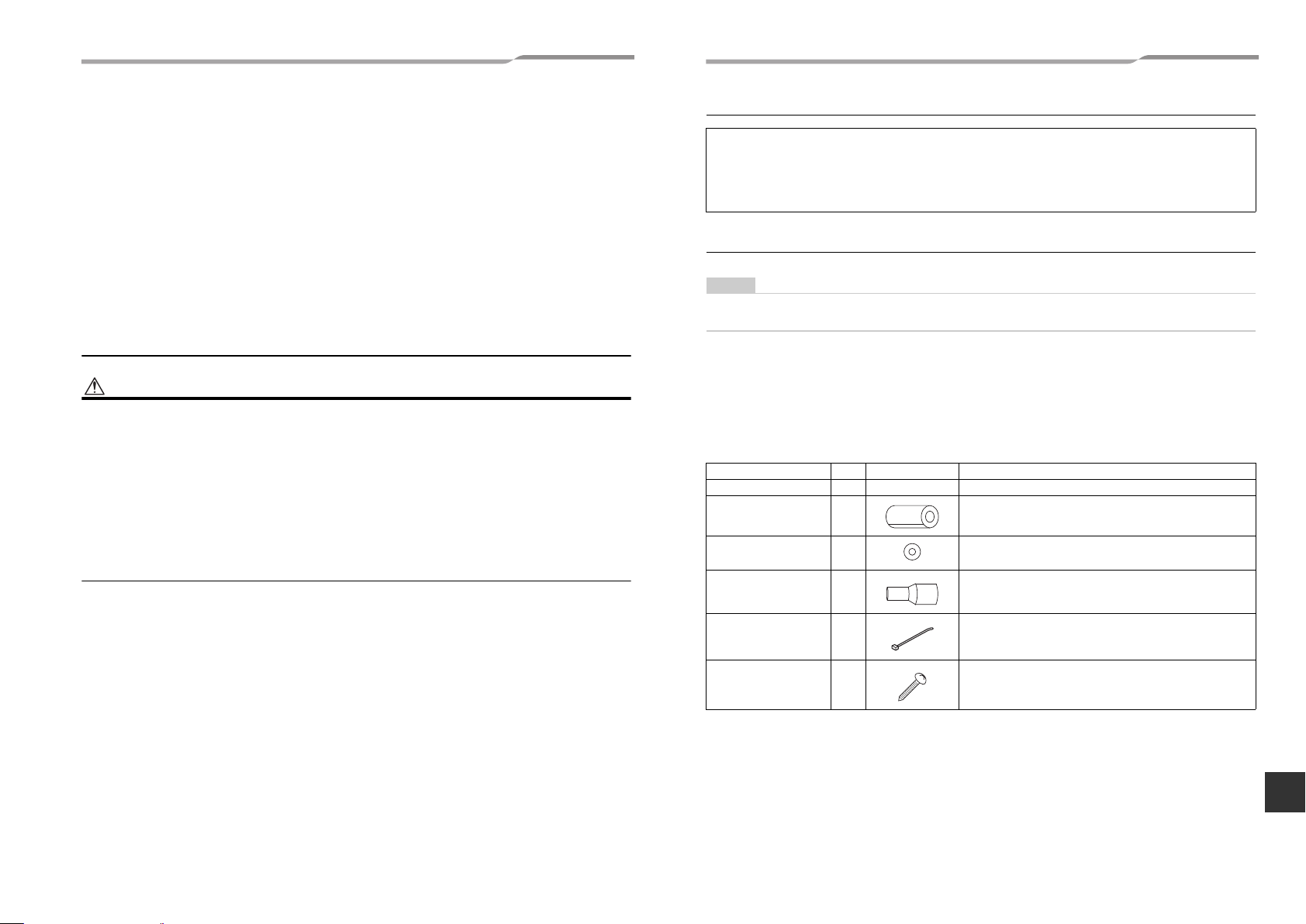
2 Accessory parts
Part name Q’ty Shape Usage
Installation Manual 1 This manual (Hand over to customers)
Heat insulating pipe 2 For heat insulation of pipe connecting section
Washer 8 For hanging-up unit (M10 × Ø34)
Drain socket 1 For connect drain pipe
Banding band 2 For fixing of pipe connecting heat insulator
Screw 8
3-EN 4-EN
–2–
For attaching a fan guard (sold separately) for air intake from
underneath
EN
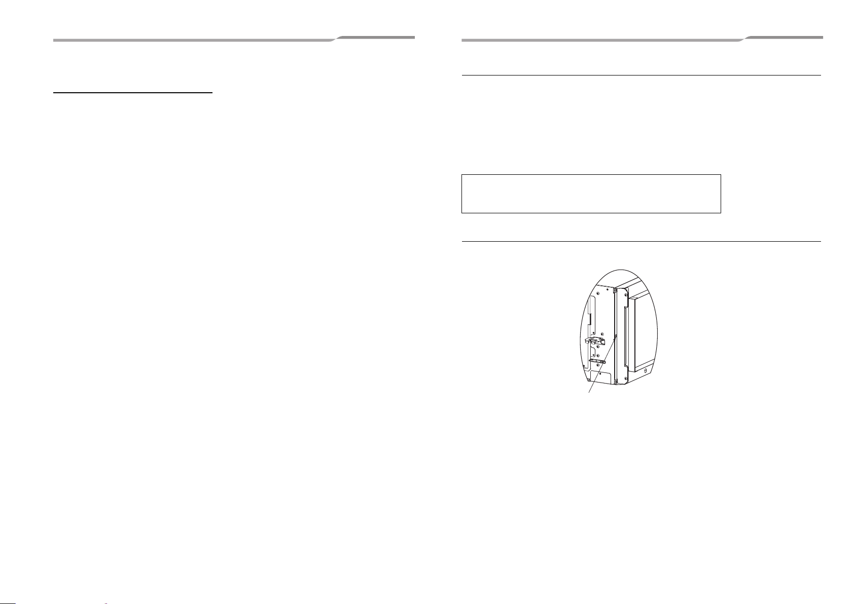
–3–
Fixing screw for shipping
3 Selection of installation place
Avoid installing in the following places
Select a location for the indoor unit where the cool or warm air will circulate evenly.
Avoid installation in the following kinds of locations.
• Saline area (coastal area).
• Locations with acidic or alkaline atmospheres (such as areas with hot springs, factories where chemicals or
pharmaceuticals are made and places where the exhaust air from combustion appliances will be sucked into the
unit).
Doing so may cause the heat exchanger (its aluminum fins and copper pipes) and other parts to become
corroded.
• Locations with atmospheres with mist of cutting oil or other types of machine oil.
Doing so may cause the heat exchanger to become corroded, mists caused by the blockage of the heat
exchanger to be generated, the plastic parts to be damaged, the heat insulators to peel off, and other such
problems to result.
• Locations where vapors from food oils are formed (such as kitchens where food oils are used).
Blocked filters may cause the air conditioner’s performance to deteriorate, condensation to form, the plastic parts
to be damaged, and other such problems to result.
• Places where iron or other metal dust is present. If iron or other metal dust adheres to or collects on the interior
of the air conditioner, it may spontaneously combust and start a fire.
• Locations near obstructions such as ventilation openings or lighting fixtures where the flow of the blown air will
be disrupted (a disruption of the air flow may cause the air conditioner’s performance to deteriorate or the unit to
shut down).
• Locations where an in-house power generator is used for the power supply.
The power line frequency and voltage may fluctuate, and the air conditioner may not work properly as a result.
• On truck cranes, ships or other moving conveyances.
• The air conditioner must not be used for special applications (such as for storing food, plants, precision
instruments or art works).
(The quality of the items stored may be degraded.)
• Locations where high frequencies are generated (by inverter equipment, in-house power generators, medical
equipment or communication equipment).
(Malfunctioning or control trouble in the air conditioner or noise may adversely affect the equipment’s operation.)
• Locations where there is anything under the unit installed that would be compromised by wetness.
(If the drain has become blocked or when the humidity is over 80 %, condensation from the indoor unit will drip,
possibly causing damage to anything underneath.)
• In the case of the wireless type of system, rooms with the inverter type of fluorescent lighting or locations
exposed to direct sunlight.
(The signals from the wireless remote control may not be sensed.)
• Locations where organic solvents are being used.
• The air conditioner cannot be used for liquefied carbonic acid cooling or in chemical plants.
• Location near doors or windows where the air conditioner may come into contact with high-temperature, highhumidity outdoor air.
(Condensation may occur as a result.)
• Locations where special sprays are used frequently.
Installation under high-humidity atmosphere
In some cases including the rainy season, especially inside of the ceiling may become high-humidity atmosphere
(dew-point temperature: 73 °F (22.8 °C) or higher).
1. Installation to inside of the ceiling with tiles on the roof
2. Installation to inside of the ceiling with slated roof
3. Installation to a place where inside of the ceiling is used for pathway to intake the fresh air
4. Installation to a kitchen
• In the above cases, additionally attach the heat insulator to all positions of the air conditioner, which come to
contact with the high-humidity atmosphere. In this case, arrange the side plate (Check port) so that it is easily
removed.
• Apply also a sufficient heat insulation to the duct and connecting part of the duct.
[Reference] Condensation test conditions
Indoor side:
Air volume: Low air volume, operation time 4 hours
80 °F (26.7 °C) dry bulb temperature
75 °F (23.9 °C) wet bulb temperature
Preparation before installation
Remove a fixing screw for shipping from the cover plate of the filter rack, and block the screw hole with tape.
5-EN 6-EN
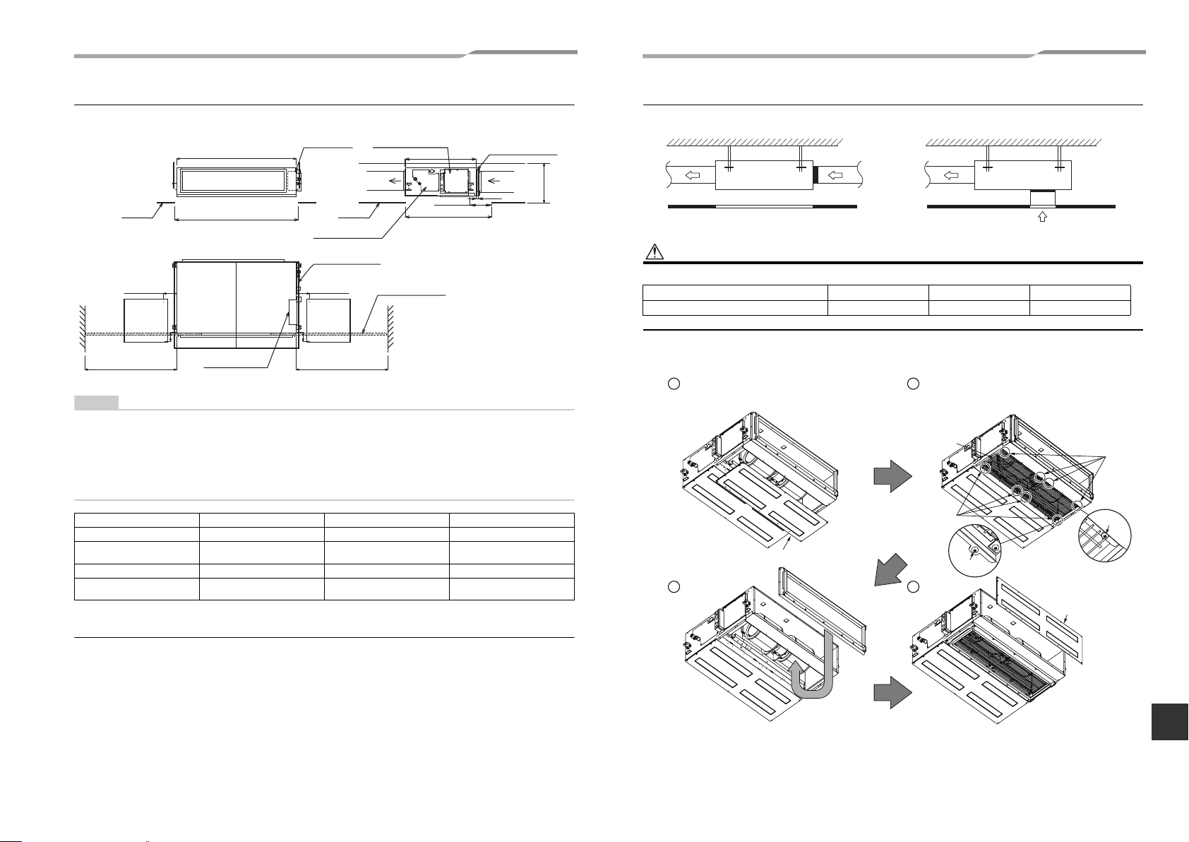
Installation space Unit: in (mm)
NOTE
Electrical control box
Air filter
(locally procured)
5.9” (150)
Ceiling opening size
15.5” (400)
(Min.) *1
Air discharge
Ceiling opening size C
Electrical
control box
Check port A
17.7” × 17.7”
(450 × 450)
Air discharge
5.9” (150) or more
Air intake
1.2” (30)
Ceiling
Ceiling
Unit width
31.5” (800)
Ceiling opening size
38.6” (980)
Drain pan / Drain
pump check cover
Space required for attaching or
detaching the filter D
Check port B
17.7” × 17.7”
(450 × 450)
Air filter
(locally procured)
Space required for attaching or
detaching the filter D
5.9” (150) or more
4” (100)
Electrical control
box
4” (100)
*1:
For air intake from
underneath, reserve a
space of 17.7” (450 mm)
or more.
CAUTION
1
3
2
4
Screw
Screw
Screw
Screw
Remove the cover plate A.
Fix the cover plate A.
Fan guard
Attach a separately-sold fan guard.
Use the supplied screws.
Remove the filter
flange and then fix it to
the bottom surface.
Reserve sufficient space required for installation or service work.
Arranging the under intake type
<Back air intake> <Under air intake>
For air intake from under air intake, be sure to attach a separately-sold fan guard.
Model MMD- AP007 to AP012 AP015 to AP018 AP021 to AP048
FAN-GUARD
model name TCB-IG071BUL TCB-IG151BUL TCB-IG211BUL
For air intake from under air intake, replace the cover (A) and filter flange as shown below before installing
the unit.
• Set check port A for maintaining the electrical control box, filter, drain pump, drain pipe, and refrigerant pipe.
• Replace the filter through check port A or B.
(If you pull out the filter in the opposite direction of the electrical control box, check port B is required.)
Reserve space D required for attaching or detaching the filter.
Otherwise, the filter cannot be replaced.
• When pulling the refrigerant pipe, drain pipe, etc., avoid the filter port. Otherwise, the filter cannot be replaced.
• The indoor unit is not equipped with an air filter. Procure and install one locally.
• Set a ceiling opening port for maintaining the fan, fan motor, etc. Otherwise, they cannot be maintained.
MODEL MMD- AP007 to AP012 AP015 to AP018 AP021 to AP048
Unit width 21.7” (550) 39.4” (1000) 53.2” (1350)
Air filter width 20” (508)
Ceiling opening size C 23.6” (600) 41.3” (1050) 55.1” (1400)
Space required for attaching or
detaching the filter D
Filter cleaning sign term setting
23.6” (600) 23.6” (600) 40.5” (1030)
The lighting term setup of the filter sign (Notification of filter cleaning) of the remote control can be changed
according to the condition of installation.
For setup method, refer to “Filter sign setting” in the Applicable controls of this Manual.
7-EN 8-EN
38” (18”+20”)
(965 (457+508))
52” (20”+20”+12”)
(1321 (508+508+305)
–4–
EN
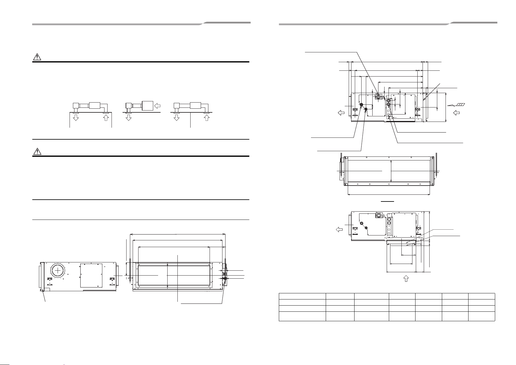
4 Installation
WARNING
CAUTION
GOOD NO GOOD NO GOOD
1 room
Hanging bolt 4-M0.4”(10)
(locally procured)
Hanging bolt pitch B
Unit external dimension A
Air discharge flange outside C
5.5” (140)
1.7” (44)
1.9” (49)
Outside
8.6” (218.2)
5.8” (147.5)
Air filter slot
Drain pipe connecting port
VP25(Polyvinyl chloride tube:
External Dia,1-1/4” Internal Dia,1”
Refrigerant pipe connecting
port ØF
(Gas side)
Air discharge
side
Air intake
side
Z
Hanging bolt pitch 27.6” (700)
Unit external dimension 31.5” (800)
2.2” (57)
2.4” (59)
1” (25)
1.6” (41)
25.1” (638)
2” (50)
19.6” (498)
15.1” (384)
1.6” (41)
5.2” (131)
2” (50)
Refrigerant pipe connecting
port ØG
(Liquid side)
Ø1” (26) Hole for contorol wire
and remote control wiring
Ø7/8” (22.2) Hole for power supply cable
9.5” (240)
6.3”
(160.5)
12.6” (320)
1.7” (42)
5” (127)
Outside
9.6” (243.2)
Air intake flange outside D
Z view
Air filter slot
1.2” (30)
Air discharge side
Air intake side
Air filter slot
Air intake flange
12.6” (320)
2.2” (57)
3.6” (91)
1.2” (30)
6.3”
(159)
9.6” (243.2)
12.6” (320)
<Under air intake>
<Back air intake>
• Install the air conditioner certainly at a place to sufficiently withstand the weight.
• If the strength is insufficient, the unit may fall down resulting in human injury.
• Perform a specified installation work to guard against an earthquake.
• An incomplete installation can cause accidents by the units falling and dropping.
• Do not install the indoor unit in the way that it takes in the air in the ceiling and provides it into the room. The indoor
unit must be installed in the way that it takes in the air from the room and returns it back to the room.
• This unit and it’s ducting (supply and return air) are intended for use in one room only.
Strictly comply with the following rules to prevent damage of the indoor units and human injury.
• Do not put a heavy article on the indoor unit or let a person get on it. (Even units are packaged)
• Carry in the indoor unit as it is packaged if possible. If carrying in the indoor unit unpacked by necessity, use buffering
cloth or other material to not damage the unit.
• To move the indoor unit, hold the hooking brackets (4 positions) only.
Do not apply force to the other parts (refrigerant pipe, drain pan, foamed parts, resin parts or other parts).
• Carry the package by two or more persons, and do not bundle it with plastic band at positions other than specified.
• To install vibration isolation material to hanging bolts, confirm that it does not increase the unit vibration.
External dimensions Unit: in (mm)
–5–
9-EN 10-EN
Model MMD- A B C D F G
AP007, AP009, AP012 21.7” (550) 24.3” (616) 13.9” (351.6) 18.6” (471.6) 3/8” (9.5) 1/4” (6.4)
AP015, AP018 39.4” (1000) 42” (1066) 31.6” (801.6) 36.3” (921.6) 1/2” (12.7) 1/4” (6.4)
AP021, AP024, AP030,
AP036, AP042, AP048
53.2” (1350) 55.7” (1416) 45.4” (1151.6) 50.1” (1271.6) 5/8” (15.9) 3/8” (9.5)
 Loading...