

Toshiba MK-150FA series User Manual
MK-150FA SERIES
Contents
of
5.25-INCH
this
manual are
FIXED
DISK
DRIVES
OEM MANUAL
TOSHIBA AMERICA, INC.
DISK PRODUCTS DIVISION
subject
to
change
without
prior
notice.
Copyright
1988, 1989 Toshiba America, Inc.
All
rights
reserved
Document Number D
W54-0
1-007-02
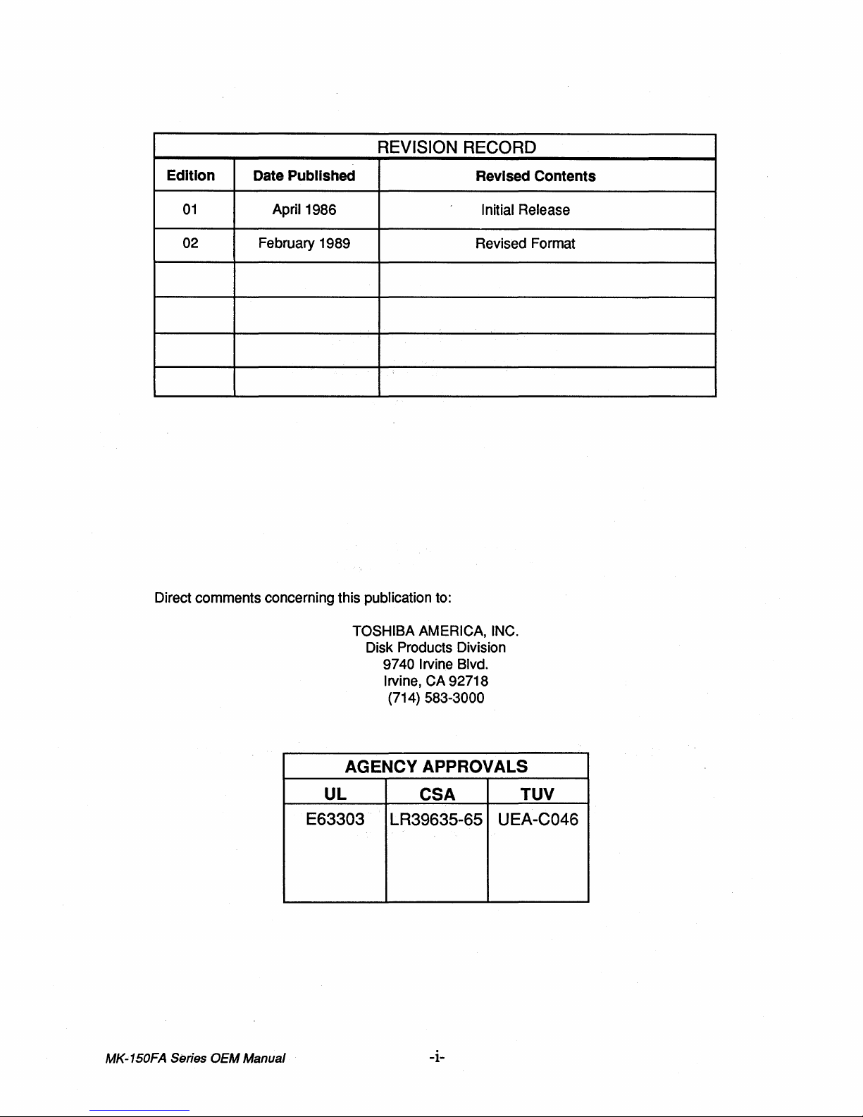
REVISION RECORD
Edition
01
02
Date
Published
April 1986
February 1989
Revised Contents
Initial Release
Revised Format
Direct comments concerning this publication to:
TOSHIBA AMERICA, INC.
Disk Products Division
9740 Irvine Blvd.
Irvine, CA
(714)
583-3000
AGENCY APPROVALS
UL
E63303
CSA
LR39635-65
92718
TUV
UEA-C046
MK-150FA Series
OEM
Manual
-i-
TABLE OF CONTENTS
SECTION 1
1.1
1.2
1.3
SECTION 2
2.1
2.2
2.3
2.4
2.5
2.6
SECTION 3
3.1
3.2 Cooling and Disk Drive Enclosures
3.3 Switch and Jumper Functions
INTRODUCTION
Purpose of Manual
Related Documents
Ge neral Description
SPECIFICATIONS
Storage Capability
Functional Specifications
Environmental Specifications
Reliability Characteristics
Power Requirements
Physical Dimensions, Weight and Mounting
INSTALLATION
Mounting Orientation
3.3.1
3.3.2
3.3.3
PJ7 Jumper Functions
PJ5 and
PJ31
Jumper Functions
PJ32 Jumper Functions
PAGE
1-1
1-1
1-2
2-1
2-1
2-2
2-3
2-4
2-5
3-1
3-1
3-2
3-3
3-4
3-4
SECTION 4
INTERFACE
4.1
Control Cable
4.2
4.3
4.4
4.5
4.6
4.7
4.8
4.9
Cable
Data
Control
Data
Cable Pin ASSignments 4-2
Cable Pin Assignments
ESDI Commnad Configuration and Functions 4-4
Request Status Command 4-5
Configuration Data Command Modifiers 4-6
Configuration Data Response
Control Command Modifiers
4.10 Data Strobe Offset Command 4-8
4.11 Track
SECTION 5
5.1
Offset Command 4-8
DATA
FORMATS
Hard Sector Format
5.2 Soft Sector Format
5.2.1
Speed Variance Gap
5.3 Defect Map Format 5-2
SECTION 6 MAINTENANCE CONSIDERATIONS
6.1
Equipment Maintenance
6.1.1
In-Warranty Maintenance
6.1.2 Out-of-Warranty Maintenance
6.1.3
Equipment Return
Instructions
4-1
4-1
4-3
4-7
4-7
5-1
5-1
5-2
6-1
6-1
6-1
-ii-
MK-1S0FA Series
OEM
Manual
TABLE LIST
TABLE
1
2
3
4 Environmental Specifications
5
6
7 PJ7 Jupmpers for 65 x 256 byte
8
9
10 Data Cable Pin Assignments 4-3
11
12
13
14 Configuration Data
15 Configuration Data Response
16
17
18
TITLE
Related Documents
Sto rage Capability
Functional Specifications
Reliability Characteristics
Power Requirements 2-4
Common PJ7 Jumper Configuration 3-4
Control Cable Pin Assignments 4-2
ESDI Command Configuration
ESDI Command Functions
Request Status
Control Command Modifiers
Data Strobe Offset
Offset Command Modifier Bits
Track
Command
Command Modifiers 4-6
Command Modifier Bits
PAGE
1-1
2-1
2-1
2-2
2-3
3-3
4-4
4-4
4-5
4-7
4-7
4-8
4-8
FIGURE
1
2
3
4 Switch and Jumper Settings
5
6
7 PJ32 Jumper
8
9
10
TITLE
MK-150FA Dimensions and Mounting
Mounting Orientation
Clearance Requirements
SW1
(Switch 1) Functions
SW2 (Switch
Hard Sector Format
Soft Sector Format
Defect Map Format
2)
Functions
FIGURE LIST
Holes
PAGE
2-5
3-1
3-1
3-2
3-2
3-2
3-4
5-1
5-2
5-3
MK-150FA Series
OEM
Manual
-iii-
SECTION
1
INTRODUCTION
1.1
The purpose ofthis manual is to describe the MK-150FA Series 5 .25-inch fixed disk drives to the level of detail
required for product integration.
System designers planning to develop a custom controller and others who require additional product
information should refer to the MK-150FA Series Product Specification for more details.
PURPOSE OF MANUAL
1.2 RELATED DOCUMENTS
Detailed product and interfacing information is given in the M K-150 FA Series Product Specification I docu
number 71Y101397.
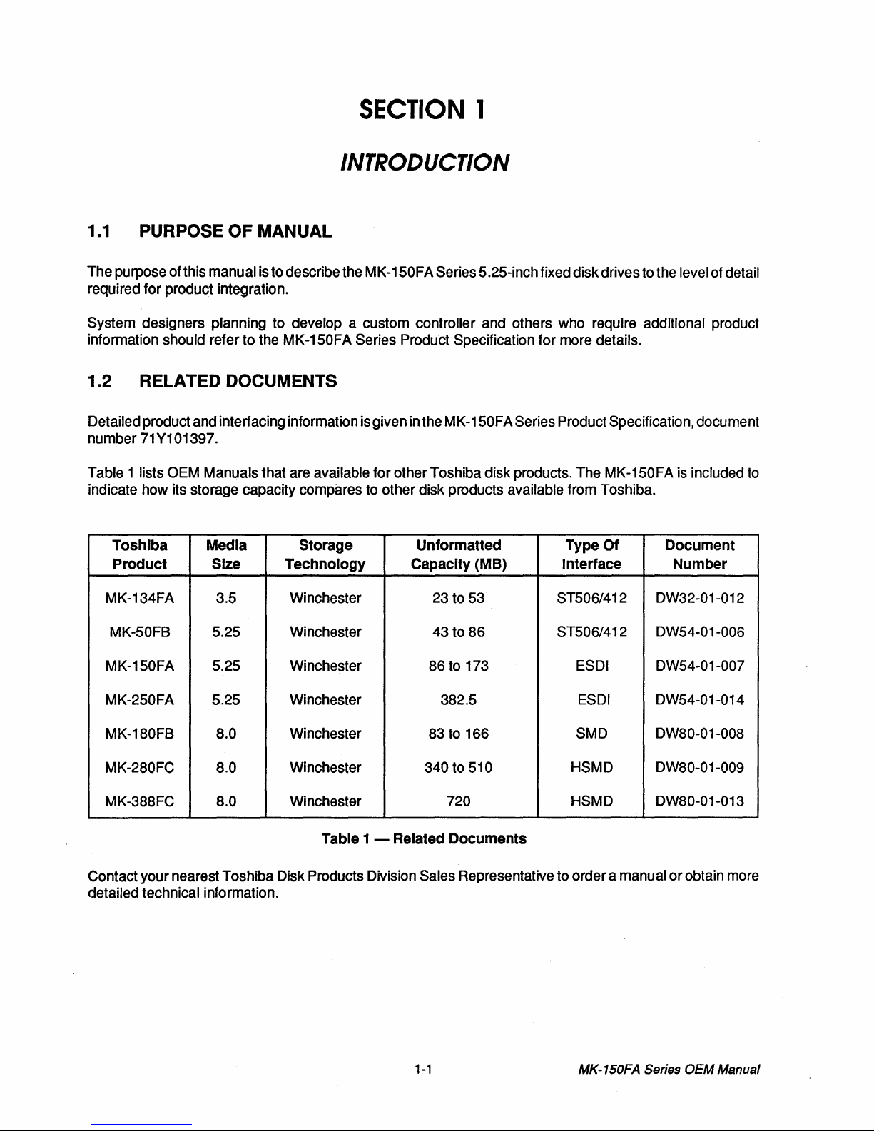
Table 1 lists
indicate how its storage capacity compares to other disk products available from Toshiba.
Toshiba
Product
MK-134FA
MK-50FB 5.25 Winchester 43 to
OEM Manuals that are available for other Toshiba disk products. The MK-150FA is included to
Type
Media
Size
3.5 Winchester 23 to 53
Storage
Technology
Unformatted
Capacity
(MB)
86
ST506/412
ST506/412
Of
Interface
Document
Number
DW32-01-012
DW54-01-006
me
nt
MK-150FA 5.25 Winchester 86 to 173 ESDI
MK-250FA 5.25 Winchester 382.5 ESDI
MK-180FB
MK-280FC 8.0 Winchester 340 to 510 HSMD
MK-388FC 8.0
Contact your nearest Toshiba Disk Products Division Sales Representative to order a manual
detailed technical information.
8.0 Winchester 83 to 166
Winchester 720 HSMD
Table
1 - Related
Documents
1-1
SMD
MK-150FA Series
DW54-01-007
DW54-01-014
DW80-01-008
DW80-01-009
DW80-01-013
or
obtain more
OEM
Manual
1.3 GENERAL DESCRIPTION
The MK-150FA Series is a family of 5.25-inch Winchester disk drives designed primarily to be incorporated
into systems supporting multi-user and multi-tasking applications. Three models comprise the MK-150FA
Series: MK-153FA (86.5 MB), MK-154FA
(121
MB) and MK-156FA (173 MB).
All drives comply with the
The MK-150FA
Series supports the Enhanced Small Disk Interface (ESDI). ESDI provides device level
capabilities for multi-spindle
ST506/412 size, mounting and power requirements
or
highly optimized applications.
The positioning system utilizes a rare earth magnet and a rotary voice coil actuator to provide a 25 millisecond average
seek
time and a 45 millisecond
maxim~m
seek time.
The Head Disk Assembly (HDA) is enclosed in a die cast aluminum base plate and shroud and incorporates
numerous safety features to maximize reliability:
The base plate and shroud assembly provides mechnical mounting and EMI (Electronic
Magnetic Interference) shielding for the heads, disks and actuator.
The sealed assembly incorporates an air recirculatory system and a
0.3 micron lifetime filter
to ensure a contamination-free environment and even thermal distribution.
in
A barometric filter
the HDA provides ambient pressure equalization.
When power is removed, a fail-safe system automatically returns the heads to a dedicated
landing zone and a solenoid automatically locks the carriage in this location. This prevents
head
and media damage during transit.
Use of a center stack servo system improves head positioning accuracy across the full environmental
operating range and allows servo writing to be performed with the disk stack mounted in the drive.
Careful planning in regard to the location of components on the circuit card, especially those with electrical
noise potential, contributes to very low
To further reduce read channel
Extensive use of
VLSI minimizes the number of components and optimizes MTBF (Mean Time Between
nOise,
levelS of read channel noise and enhances data recovery.
DC voltages are filtered before being used on the read channel.
Failures).
MK-150FA Series
OEM
Manual
1-2

SECTION 2
SPECIFICATIONS
2.1
STORAGE CAPABILITY
STORAGE CAPACITY
Unformatted Capacity
Number
Number
Number
of
Disks
of
Data ReadlWrite Heads
of
Tracks
Table 2 - Storage Capability
2.2 FUNCTIONAL SPECIFICATIONS
Specifications are the same
Number of Cylinders
Track Capacity
Tracks per Inch
Bits per Inch
Flux Changes per Inch
MK-153FA
86.5
4,150
MK-154FA MK-156FA
MB
121.0 MB 173.0 MB
3 4 6
5
for
7
5,810 8,300
all models
830
20,832
Bytes
900 TPI
18,766 BPI
12,510 FCI
10
Recording Method
Data Transfer Rate
Head Recovery Time:
Change
Head
Write
to
Read
Seek Time: (includes settling)
Track-to-Track
Average
Full Stroke
Time
Start
Stop Time
Rotational
Average Latency Time
Maximum Latency Time
Acoustic Noise
Speed
10.0 Megabits per Second
13 Microseconds
8 Microseconds
5 Milliseconds
23 Milliseconds
45 Milliseconds
20 Seconds
20 Seconds Typical - 30 Seconds Maxim
Typical-
3,600 RPM ± 1 %
8.33 Milliseconds
17.10 Milliseconds
50 dBA at 3.0 Feet
Table 3 - Functional Specifications
2,7 (RLL)
30 Seconds Maximum
(1
Meter)
um
2-1
MK-150FA Series
OEM
Manual
2.3 ENVIRONMENTAL SPECIFICATIONS
Specifications
Operating Environment:
Ambient Temperature
Temperature Gradient
Relative
Altitude
Vibration
:Shock (recoverable errors allowed) 10.0 G Peak*
Cooling:
Convection Cooling
Non-Operating (Unpacked) Environment:
Ambient Temperature
Humidity
(all axis)
are
the
same
for
all
models
41
° to 122° F (5° to 50° C)
27° F per Hour (15° C)
Maximum Wet Bulb 84° F (29° C)
20
to
80%, No Condensation
-1000
(-300
0.25 G Peak at 5-200 Hz
Any enclosure (see Section 3) must
allow the drive to operate within specified
environmental limits.
14° to 122° F (-10° to 50° C)
to 10,000 Feet
to
3,000 Meters)
Temperature Gradient
Relative
Altitude
Vibration
Shock
Storage (Packed) Environment:
Ambient Temperature
Temperature Gradient 27° F per Hour (15° C)
Relative
Altitude
Vibration 2
Shock (maximum free drop)
*When
fixed
the
rigid
Humidity
Humidity 5
to a rigid
structure.
structure
(excluding
resonance)
and
when
an
11
millisecond half-sine-wave
27° F per Hour (15° C)
0
to
80%, No Condensation
1
to 10,000 Feet
-1,000
(-300
to
15,000 Meters)
0.5 G/0.04 Inch (1.0mm) at 5-200 Hz
40.0 G Peak*
-40° to 140°F (-40° to 60° C)
to
90%, No Condensation
-1,000
to 49,000 Feet
(-400
to
15,000 Meters)
G/0.1 Inch (2.5mm) at 5-400 Hz
27
Inches (0.7 Meter)
impulse
is
applied
to
MK-150FA Series
OEM
Manual
Table
4 -
Environmental
Specifications
2-2
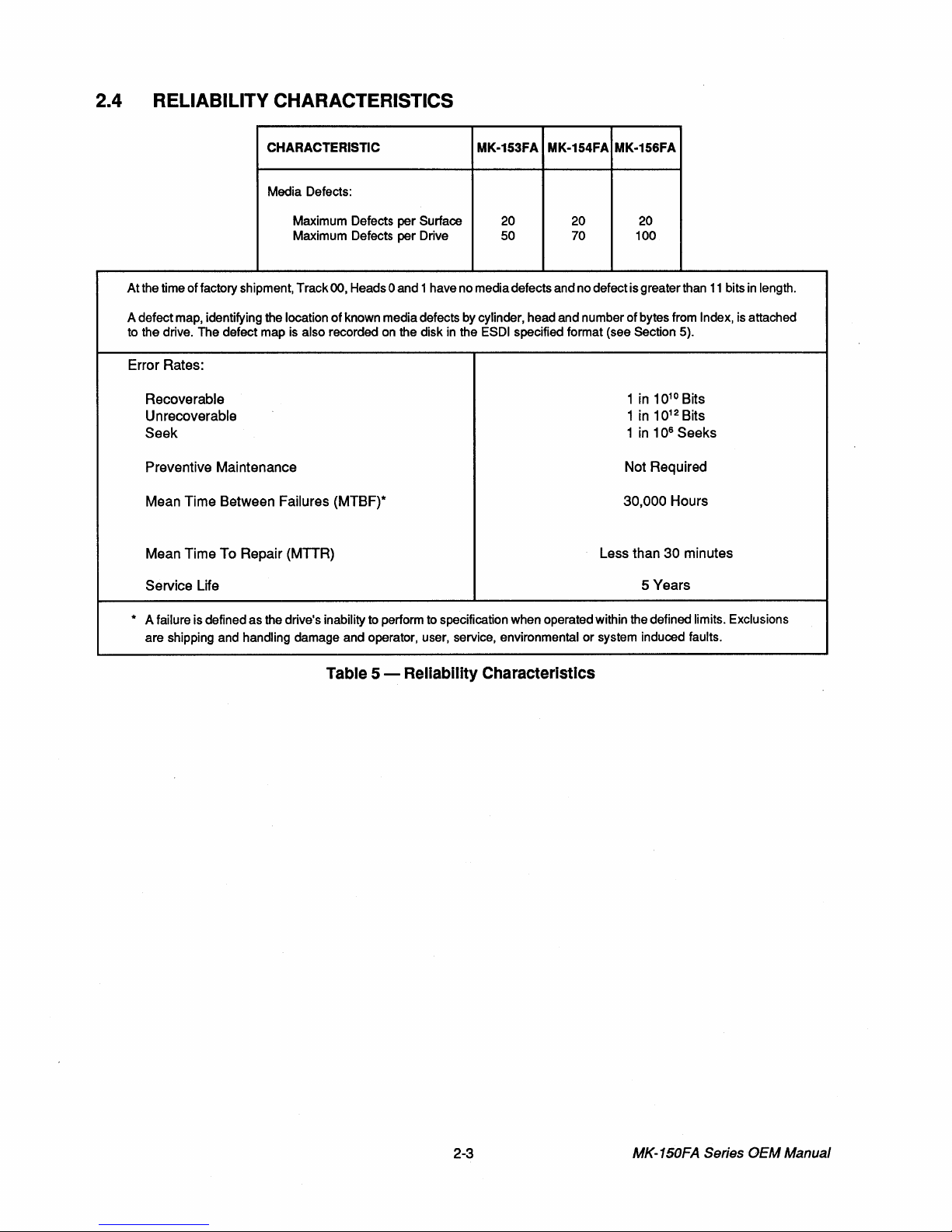
2.4 RELIABILITY CHARACTERISTICS
CHARACTERISTIC
Media Defects:
Maximum Defects per Surface
Maximum Defects per Drive
At
the time of factory shipment, Track 00, Heads 0 and 1 have no media defects and no defect is greater than
of
A defect map, identifying the location
to the drive. The defect map is
known media defects by cylinder, head and number
also recorded on the disk
MK-153FA MK-154FA MK-156FA
20
50
in
the ESDI specified format (see Section 5).
20
70
20
100
of
bytes from Index, is attached
Error Rates:
10
Recoverable
Unrecoverable
Seek
Preventive Maintenance
Mean Time Between Failures (MTBF)*
Mean Time To Repair (MTTR)
Service Life
1 in
1 in
1
in
Not Required
30,000 Hours
Less than
5 Years
10
1 06 Seeks
30 minutes
10
12
Bits
Bits
11
bits
in
length.
* A failure is defined as the drive's inability to perform to specification when operated within the defined limits. Exclusions
or
are shipping and handling damage and operator, user, service, environmental
system induced faults.
Table 5 - Reliability Characteristics
2-3
MK-150FA
Series
OEM
Manual
 Loading...