

Toshiba MK1517GAP, MK2017GAP, MK3017GAS, MK1018GAS, MK1016GAP Installation Notes
...
TOSHIBA STORAGE DEVICE DIVISION
2.5" HDD SERIES INSTALLATION NOTES - 9.5mm Series
© 2001 Toshiba America Electronic Components, Inc.
Contents subject to change without prior notice.
GENERAL DESCRIPTION
Tosh i b a's 2 . 5" Ha r d Di s k Dr i v e 9.5mm se r ies , HDDXXXX, co mp r i s e a s e r ies of f as t , hi g h capacity 2.5" Winchester disk dr ives which comply with ATA-4 and ATA-5* standards and
require o nly a s im p le ad a pte r b oa rd for in terfa c ing to sta nd a rd IDE cable s.
*ATA-5 - MK1517GAP, MK3017GA*, MK2018GA* and MK4018GA*, only
SPECIFICATIONS
MK1016
GAP
MK1017
GAP
MK1018
GAS
MK1516
GAP
MK1517
GAP
MK1517
GAP
MK2016
GAP
HDD2152 HDD2151 HDD
TBD
HDD2153
HDD2157*ZV HDD2157*ZF
HDD2154
FORMATTED CAPACITY 10.056GB 10.056GB 10.056GB 15.09GB 10.05GB 15.10GB 20.003GB
HEIGHT 9.5mm 9.5mm 9.5mm 9.5mm 9.5mm 9.5mm 9.5mm
NO. OF DISKS (PLATTERS) 1112112
NO. OF DATA HEADS 2213224
MK2017
GAP
MK2018
GAP
MK2018
GAS
MK3017
GAP
MK3017
GAS
MK4018
GAP
MK4018
GAS
HDD2158 HDD2164 HDD2154
HDD2159*ZF
HDD2160 HDD2164 HDDtbd
FORMATTED CAPACITY 20.00GB 20.004GB 20.004GB 30.00GB 30.00GB 40.008GB 40.008GB
HEIGHT 9.5mm 9.5mm 9.5mm 9.5mm 9.5mm 9.5mm 9.5mm
NO. OF DISKS (PLATTERS) 2112222
NO. OF DATA HEADS 3224444
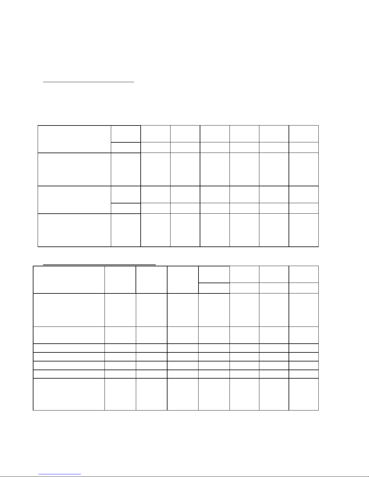
FUNCTIONAL SPECIFICATION
LOGICAL DRIVE
PARAMETERS
MK1016
GAP
MK1017
GAP
MK1018
GAS
MK1516
GAP
MK1517
GAP
MK1517
GAP
MK2016
GAP
HDD2152 HDD2151 HDDtbd HDD2153
HDD2157*ZV HDD2157*ZF
HDD2154
NO. OF CYLINDERS
(user)
21,080 21,080 TBD 21,080 TBD 25,800 21,080
BYTES PER SECTOR
512 512 TBD 512 512 512 512
BUFFER SIZE
(KBYTES)
1024 256 2048 1024 2048 2048 1024
ROTATION SPEED
(±0.1%)
4,200 4,200 4,200 4,200 4,200 4,200 4,200
TRANSFER RATE
INTERNAL
(MBITS/SEC.)
121.4 -
234.1
121.4 -
234.1
TBD 121.4 -
234.1
155.4 -
286.7
155.4 -
286.7
121.4 -
234.1
NO. OF CYLINDERS
(logical)
16,383 16,383 TBD 16,383 16,383 16,383 16,383
NO. OF HEADS
16 16 TBD 16 16 16 16
NO. OF SEC./TRACK
63 63 TBD 63 63 63 63
PI O/ULTRA DMA
(MBITS/SEC.)
16.6/66.7 16.6/66.7 TBD 16.6/66.7 TBD 16.6/100 16.6/66.7
SEEK TIME
(MSEC.)
AVERAGE 13 13 12 13 13 13 13
TRACK-TO-TRACK 3323333
MAXIMUM 24242224242424
2.5” Hard Disk Drive Installation Notes - 9.5mm Series P/N 480040-G0 P/N 480040-G0 2.5” Hard Disk Drive Installation Notes - 9.5mm Series
8/01 8/01
LOGICAL DRIVE
PARAMETERS
MK2017
GAP
MK2018
GAP
MK2018
GAS
MK3017
GAP
MK3017
GAS
MK4018
GAP
MK4018
GAS
HDD2158 HDD2164 HDD2154
HDD2159*ZF
HDD2160 HDD2166 HDDtbd
NO. OF CYLINDERS
(user)
25,800 33,280 TBD 25,800 25,800 33,280 TBD
BYTES PER SECTOR
512 512 TBD 512 512 512 TBD
BUFFER SIZE
(KBYTES)
2048 2048 2048 2048 2048 2048 2048
ROTATION SPEED
(±0.1%)
4,200 4,200 4,200 4,200 4,200 4,200 4,200
TRANSFER RATE
INTERNAL
(MBITS/SEC.)
155.4 -
286.7
156.9 –
290.4
TBD 155.4 -
286.7
155.4 -
286.7
156.9 –
290.4
TBD
NO. OF CYLINDERS
(logical)
16,383 16,383 TBD 16,383 16,383 16,383 TBD
NO. OF HEADS
16 16 TBD 16 16 16 TBD
NO. OF SEC./TRACK
63 63 TBD 63 63 63 TBD
PIO/ULTRA DMA
(MBITS/SEC.)
16.6/100 16.6/100
TBD
16.6/100 16.6/100 16.6/100
TBD
SEEK TIME
(MSEC.)
AVERAGE 13 13 12 13 13 13 12
TRACK-TO-TRACK 3323332
MAXIMUM 24242224242422
UNPACKING PROCEDURE
Visually inspect t he shipping container prior to unpacking for any signs of damage to t he
container or its contents (the carrier is responsible for any damage incurred during
shipment). The drive is a precision device and even a small drop onto any surface can cause
damage. Prior to opening the anti-static bag, it is recommended that the user ground
himself with a ground stra p or by touching the PC chassis or ot her metal object. Remove
the drive from the ant i-st ati c bag and check it for damage. Pl ace the dr ive on the ant i- stati c
bag while configuring jumpers to avoid any electrostatic discharge. Save the shipping
container and packing material for possible use later.
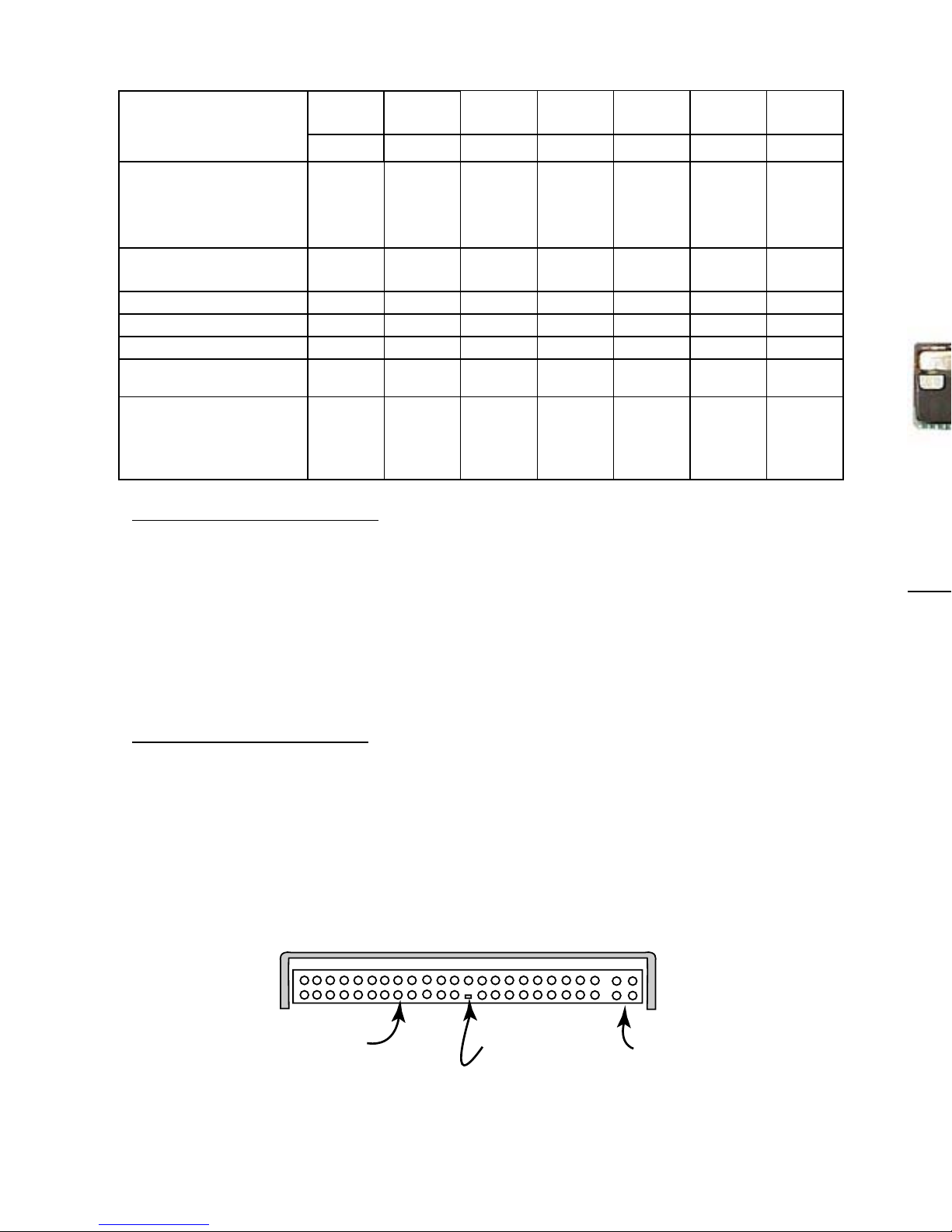
DRIVE CONFIGURATION
Toshiba's 2.5" hard disk drives can be configured as either master or slave units. Master
configuration is used for all single drive applications, and master or slave configuration
(only one of each per port) i s used for two drive applicati ons. Use the information in the
following table before setting M/S drive.
Master configuration is obtained by setting jumpers B, C & D open (no jumper). Slave
configurati on is obtained by set ting jumpers C-D. When B-D jumper is installed, the drive
is configured as cable select. If pin 28 = Low, the drive is master. If pin 28 = High, the drive
is slave.
43
KEY
PIN 20
1CA
DB
JUMPERS
INTERFACE
CONNECTOR
FIGURE 1 – 2.5" HDD JUMPER LOCATIONS
INSTALLATION INSTRUCTIONS
1. Determine mounting configuration ( can be mounted in either a hori zontal or vert ical
orientation).
2. Configure drive for system application.
3. Configure the adapter board for the specific system application (if required).
4. Install adapter board into an unused PC/AT 16 bit slot (if required).
5. Install the I/F cable to the System's 44 pin connector port or adapter board. Ensure Pin 1
is oriented correctly. (Pin 1 on the cable is usually identified by a red or blue stripe.)
6. Set correct drive type in system CMOS.
7. R efe r to ap p lica b le manuals for s o ftw a re in sta lla tion in stru c tion s.
 Loading...