

Page 1

General Precautions for Installation/Servicing/Maintenance for the MJ-5002
The installation and service should be done by a qualified service technician.
1. When installing the MJ-5002 to the Plain Paper Copier , be sure to f ollow the instructions described in
the “Unpacking/Set-Up Procedure for the MJ-5002” booklet which comes with each unit of the
MJ-5002.
2. The MJ-5002 should be installed by an authorized/qualified person.
3. Before starting installation, servicing or maintenance work, be sure to turn off and unplug the copier
first.
4. When servcing or maintaining the MJ-5002, be careful about the rotating or operation sections such
as gear, pulleys, sprockets, cams, belts , etc.
5. When parts are disassembled, reassembly is basically the rev erse of disassembly unless otherwise
noted in this manual or other related materials. Be careful not to reassemble small parts such as
screws, washers, pins , E-rings, toothed washers to the wrong places .
6. Basically, the machine should not be operated with any parts removed or disassembled.
7. Delicate parts for preventing safety hazard problems (such as breakers, thermofuses, fuses, door
switches, sensors, etc. if any) should be handled/installed/adjusted correctly.
8. Use suitable measuring instruments and tools.
9. During servicing or maintenance wor k, be sure to check the serial No. plate and other cautionary
labels (if any) to see if they are clean and firmly fixed. If not, take appropriate actions.
10. The PC board must be stored in an anti-electrostatic bag and handled carefully using a wristband,
because the ICs on it may be damaged due to static electricity. Before using the wrist band, pull out
the power cord plug of the copier and make sure that there is no uninsulated charged objects in the
vicinity.
11. For the recovery and disposal of used MJ-5002, consumable parts and packing materials, it is recommended that the relev ant local regulations/rules should be follo wed.
12. After completing installation, servicing and maintenance of the MJ-5002, retur n the MJ-5002 to its
original state, and check operation.
Copyright 2000
TOSHIB A TEC CORPORATION
Page 2

CONTENTS
1. SPECIFICATIONS....................................................................................................... 1-1
2. OUTLINE..................................................................................................................... 2-1
2.1 Names of Various Components........................................................................................ 2-1
2.2 Layout of Electrical Parts ................................................................................................. 2-2
2.3 Harness Connection Diagram .......................................................................................... 2-3
2.4 Board Assembly ............................................................................................................... 2-4
3. OPARATIONAL DESCRIPTION ................................................................................. 3- 1
3.1 General Operation............................................................................................................ 3-1
3.2 Block Diagram.................................................................................................................. 3-1
3.3 Detection of Abnormal Status ..........................................................................................3-2
3.3.1 Cover open/Close detection.................................................................................. 3-2
3.3.2 Paper jam detection .............................................................................................. 3-2
3.3.3 Stacker full detection............................................................................................. 3-2
3.4 Flow Charts...................................................................................................................... 3-3
4. MECHANICAL DESCRIPTION................................................................................... 4 - 1
4.1 Paper Feed System.......................................................................................................... 4-1
4.2 Paper Transport................................................................................................................ 4-1
4.3 Flap Function ................................................................................................................... 4-1
4.4 Drive System.................................................................................................................... 4-2
5. CIRCUIT DESCRIPTION ............................................................................................ 5-1
5.1 PWA Block Diagram......................................................................................................... 5-1
5.2 Meaning of Signals........................................................................................................... 5-2
5.3 Timing Charts............................................................................................................... .... 5-3
6. DISASSEMBLY AND REPLACEMENT...................................................................... 6- 1
October 2000 © T OSHIBA TEC 1 MJ-5002 CONTENTS
Page 3

1. SPECIFICATIONS
Function : Exit roller moving type offset tray
Paper : Size A3 to A5-R/LD to ST-R
(Offset possible size : A3, A4, A4-R/LD, LG, LT, LT-R)
: Thickness Normal paper 64 to 163g/m2 (17 to 43 lbs)
T ransport speed : 91.6 mm/sec. (DP1600 series)
(Driven by copier) : 124.4 mm/sec. (DP2000/2500 series)
Loading capacity : Paper height : 39 mm (Approx. 250 sheets)
Shift amount : Approx. 30 mm
Dimensions : 500 (W) x 415 (D) x 169 (H) mm
Weight : Approx. 3.1 kg
Power supply : 5VDC, 24VDC (Supplied from copier)
October 2000 © T OSHIBA TEC 1 - 1 MJ-5002 SPECIFICATIONS
Page 4
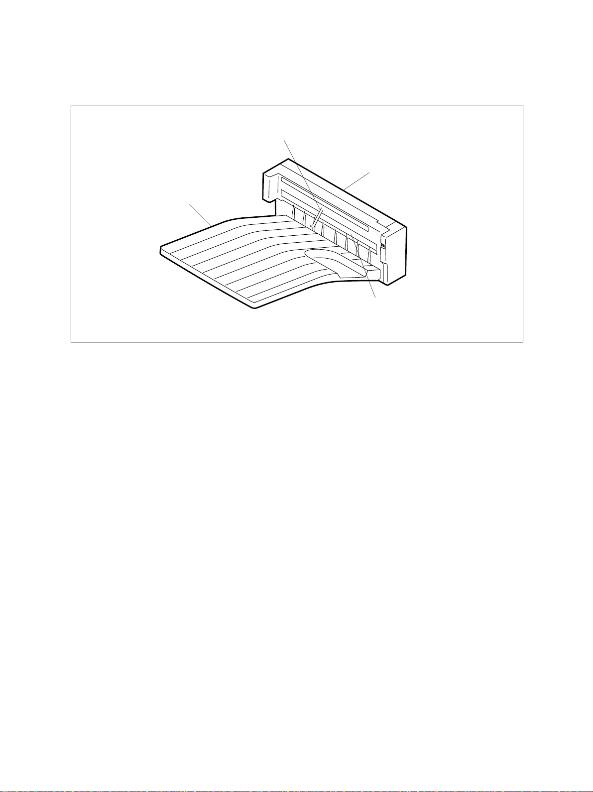
2. OUTLINE
2.1 Names of Various Components
OCT stack sensor (Arm)
OCT tray
OCT open cover
Separate roller assembly
OCT 02-01-01
October 2000 © T OSHIBA TEC 2 - 1 MJ-5002 OUTLINE
Page 5
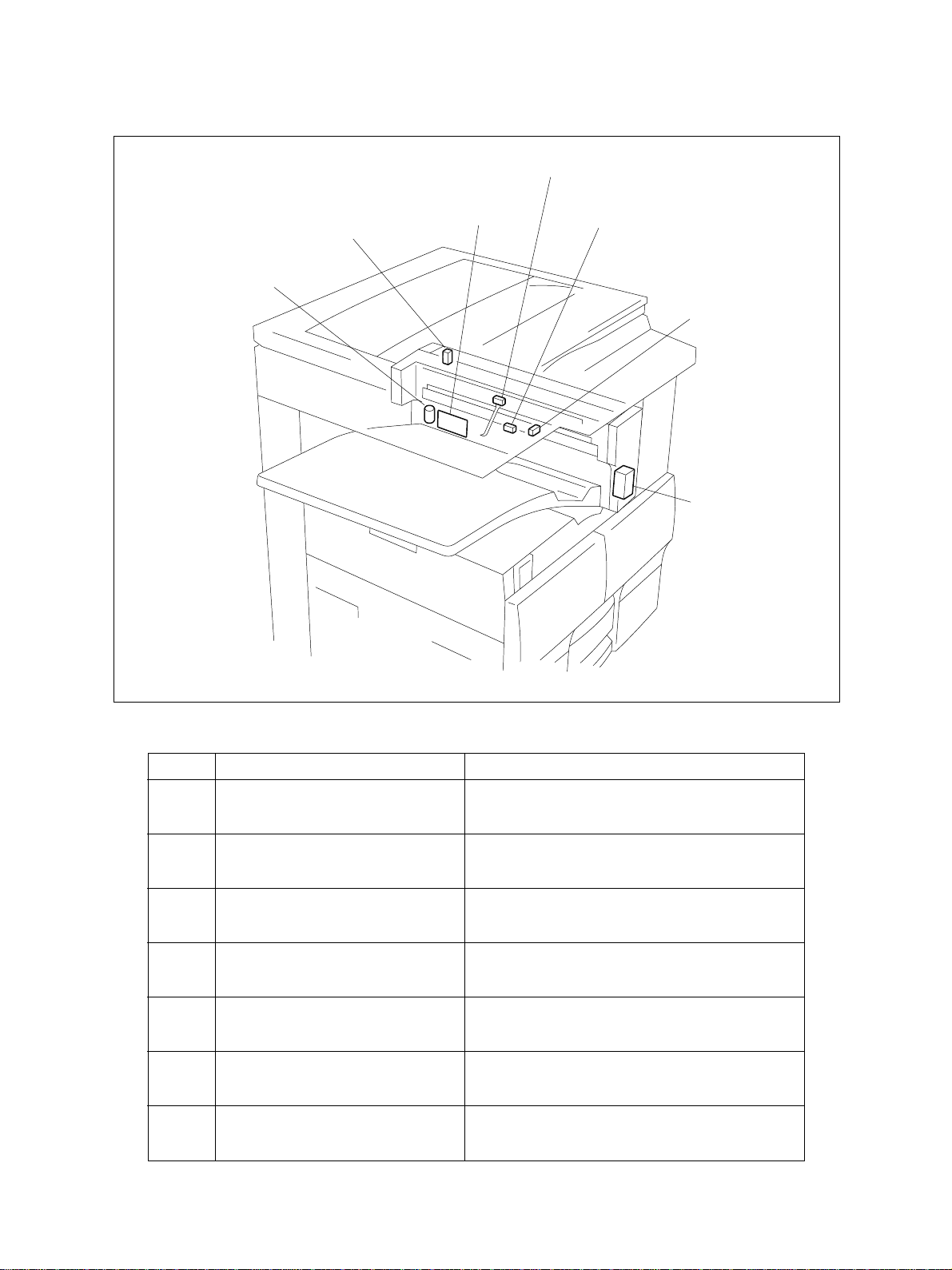
2.2 Layout of Electrical Parts
SEN1
M1
SW1
OCT (PWA-F-OCT)
SEN2
SEN3
SOL1
Symbols and functions of various devices
Symbol
SW1
OCTCOV-SW
Name
OCT cover open switch
SEN1
PF-SEN
OCT stack sensor
SEN2
INP-SEN
OCT separate sensor
SEN3
OCTFED-SEN
OCT paper feed sensor
M1
OFS-MOT
OCT motor
SOL1
OCTGATE-SOL
OCT solenoid
OCT
PWA-F-OCT
OCT PWA
OCT 02-02-01
Function
Detects the open/close state of the cover during jam processing, etc.
Detects the limit number of sheets stacked.
Detects the home position of the separator.
Detects the presence or absence of transport
paper.
Moves the separate unit right-to-left.
Switches the transport path (flap).
PWA which relays the sensor signals and solenoid drive signals and drives the motor.
MJ-5002 OUTLINE 2 - 2 October 2000 © T OSHIBA TEC
Page 6
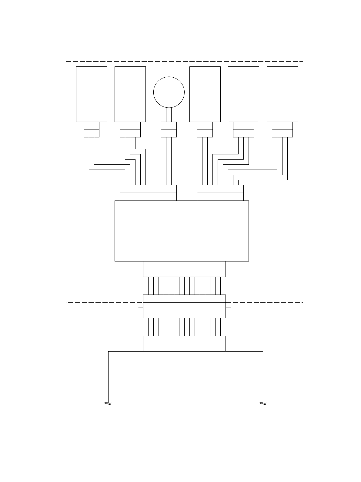
2.3 Harness Connection Diagram
2
CN330
OCT cover open switch
1
OCT stack sensor
321
CN331
123456789
SG
SG
VCC
JCOS
CN261
FLS1ON
1514131211
NC
NC
CN329
NC
OCT motor
1
2
10
OFMOT2
OFMOT1
OCT PWA
987654312
10
OCT solenoid
2
1
CN333
1234567
SG
+24V
JSSON
CN262
JOB-JAM
VCC
SG
321
CN332
8
VCC
JFLS2
OCT paper feed sensor
OCT separate sensor
321
CN343
OCT
1514131211
CN322
123456789
123456789
2
PG 3
CN41 CN260
OFFSET1
OFFSET2 1
987654312
10
4
6
+24V
JSSON 5
JOB/JAM 7
JFLS2ON
1011121315
10
8
10F/SELECT
JOB/SW 9
JCOSON
14
11
12
12SG
15JPOSON
14+5V
FLS1ON 13
JCONECT 11
Relay PWA
OCT 02-03-01
October 2000 © T OSHIBA TEC 2 - 3 MJ-5002 OUTLINE
Page 7
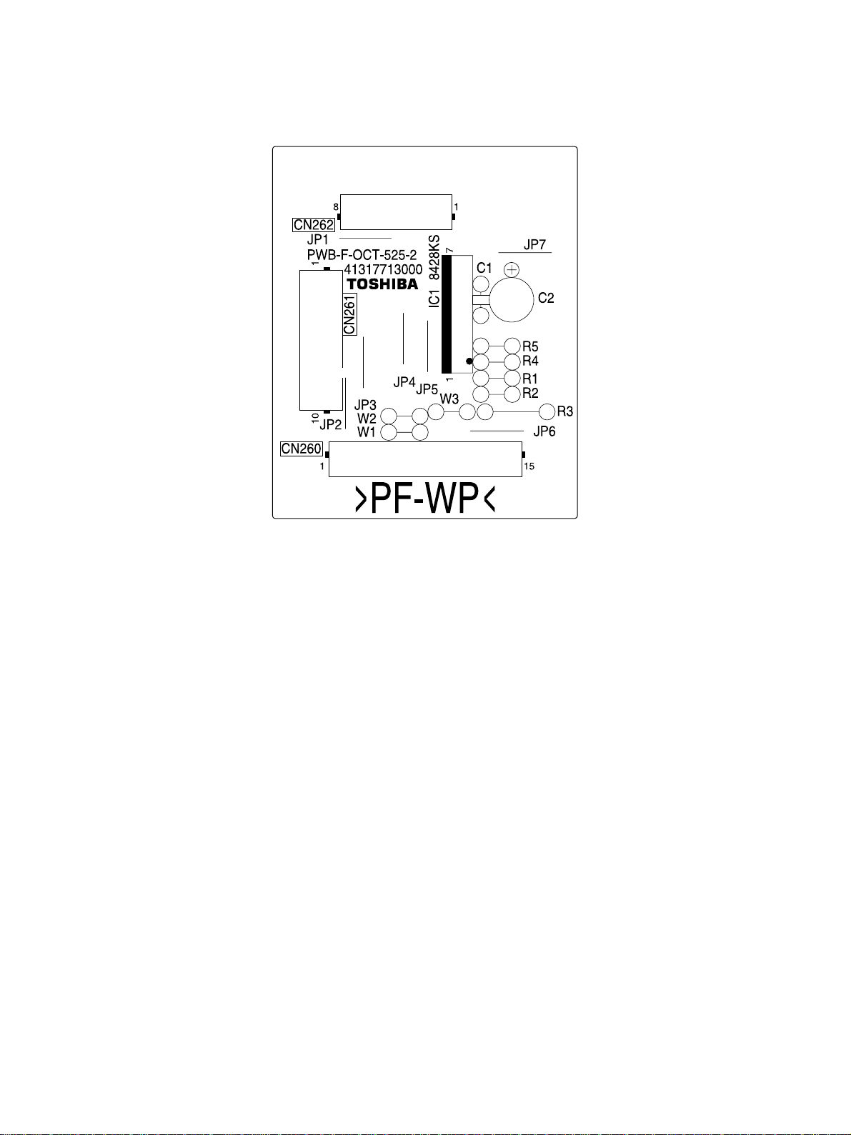
2.4 Board Assembly
OCT 02-04-01 PPS2
MJ-5002 OUTLINE 2 - 4 October 2000 © T OSHIBA TEC
Page 8
3. OPARATIONAL DESCRIPTION
3.1 General Operation
The OCT has a function to stack printed sheets of paper by putting them in the right and left stackers.
When fed to the OCT, printed paper can be stacked by putting it in the right or left stac k er . The offsetting
section is moved to the right or left by the motor.
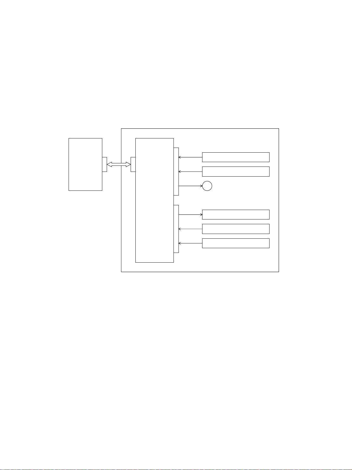
3.2 Block Diagram
OCT
Relay
PWA
CN41
CN260
JCOSON
JFLS1ON
CN261CN262
OFFSET-1,2
OCT
PWA
JSSON
JOB-JAM
JFLS2ON
OCT cover open switch
OCT stack sensor
M
OCT motor
OCT solenoid
OCT paper feed sensor
OCT separate sensor
OCT 03-02-01
Four detection switches , one solenoid, and one motor are connected to the OCT PWA. The motor drive
signals only go through the driver IC (IC1) and the other signals connect to the RELAY PWA as they are.
Those signals go through the RELAY PWA and connect to the MAIN PWA for control.
• At power-on time
At power-on time, the OCT checks the home position of the separ ate roller assemb ly through control
from the copier. If the sensor has not detected the home position at this time, the OCT motor is driven
to move the separate roller assembly to the home position.
• During offset operation
For offset stacking, the combination of the OFFSET1 and OFFSET2 signals allo ws the OCT motor to
operate and move the separate roller assemb ly to the right or left. If specified f or a size of paper which
cannot be offset, offset stacking will be ignored on the copier side.
October 2000 © T OSHIBA TEC 3 - 1 MJ-5002 OPERATIONAL DESCRIPTION
Page 9

3.3 Detection of Abnormal Status
3.3.1 Cover open/Close detection
When the OCT cover open s witch detects the open state of the cov er , the copier detects it and stops the
transport of paper.
3.3.2 Paper jam detection
If the paper fed from the copier is jammed in the transport path, the OCT paper feed sensor detects
paper jamming. The signal is at “High” le v el while the paper is passing. If the “High” level time is too long,
the copier will judge it to be paper jamming.
3.3.3 Stacker full detection
When the stacker is full of paper , a stac ker full state is detected b y the OCT stack sensor . The stac ker full
state can be cleared by removing the paper from the stacker. This detection is effective only when the
OCT is operating so that no stacker full state occurs when the sensor is turned on while taking out the
paper from the stacker.
MJ-5002 OPERA TIONAL DESCRIPTION 3 - 2 October 2000 © TOSHIBA TEC
Page 10

3.4 Flow Charts
Start button ON
Main motor ON
Polygon motor ON
Process unit fan motor high speed rotation
Development bias ON
Separation bias ON
Charge bias ON
Discharge lamp ON
Process system control Optical system control
Transfer system control
Retraction of carriage
Polygon motor
OK?
YES
Laser ON
Transfer bias ON
NO
Service call
"CA1"
Main motor
OK?
YES
Pickup clutch ON
Feed sensor
NO
Service call
"C01"
NG
Black shading
Exposure lamp ON
Stop of carriage
check
Transfer guide bias ON
Laser OFF
OK
Pickup clutch OFF
Paper jam
"E13"
Advance of carriage
White shading
Registration roller
Transfer bias OFF
Transfer guide bias OFF
clutch ON
Registration roller
clutch OFF
Scanning of document
Stop of carriage
Exposure lamp OFF
Retraction of carriage
Stop of carriage
NO
HSYNC
OK
YES
Remaining
copy count 0?
NO
Service call
"CA2"
NO
Remaining
copy count 0?
YES
Exit sensor
NG
check 1
YES
Polygon motor OFF
End of process
system control
OK
Exit sensor
check 2
OK
Paper jam
"E01"
NG
Paper jam
"E02"
End of optical
system control
A
October 2000 © T OSHIBA TEC 3 - 3 MJ-5002 OPERATIONAL DESCRIPTION
Page 11

A
OCT paper
NG
feed sensor
check
OK
Detected by
Paper jam
"E02"
YES
OCT stack
sensor?
Exit tray full
NO
Charge bias OFF
Main motor OFF
Development bias OFF
Separation bias OFF
Discharge lamp OFF
Process unit fan motor low speed rotation
Standby
MJ-5002 OPERA TIONAL DESCRIPTION 3 - 4 October 2000 © TOSHIBA TEC
Page 12

4. MECHANICAL DESCRIPTION
4.1 Paper Feed System
- - - - - Pr inted on one side in duplex printing
Standard ejection
OCT stack sensor
Flap
OCT paper feed sensor
OCT separate sensor
OCT solenoid
OCT 04-01-01
4.2 Paper Transport
For the transport path for paper, the paper coming out from the exit roller of the copier enters the OCT
and runs over the sensor , flap and separate roller assembly to the stac ker in this order as indicated b y the
arrow as shown in the figure above (solid line).
4.3 Flap Function
The flap is driven by the OCT solenoid. In duplex printing, the flap is lowered when one-side-printed
paper is fed. This allows the paper to be loaded into the copier again without catching on the roller (dotted
line).
The OCT exit sensor is located at the exit, which detects the limit number of sheets stacked. It detects
the stacker full state (approx. 39 mm, min. 250 sheets) when the number of sheets stacked increases to
raise the sensor arm.
October 2000 © T OSHIBA TEC 4 - 1 MJ-5002 MECHANICAL DESCRIPTION
Page 13

4.4 Drive System
Separator roller assembly
OCT motor
To transport paper, driving force is delivered from
the copier through gears. Driving input from the
Flow of paper
OCT 04-04-01
OCT motor
copier is transmitted through the four gears to turn
the roller shaft and transport the paper.
The separator roller assembly is slid about 30 mm
right-to-left by the OCT motor . When using the offset stacking function, the separator roller is mov e d
right-to-left for every sheet or every set of sheets.
The OCT motor contains a brush motor and drives
the OCT motor arm right-to-left through the combination of gears, etc. The OCT motor arm is mov ed
right-to-left by the operation of the motor. The internal mechanism cuts the driving of the motor when
the arm moves 30 mm so that the arm will not move
beyond there or the motor will not be overloaded.
The flap is controlled by moving the arm connected
to the OCT solenoid. When the OCT solenoid turns
ON, the arm lowers to push down the flap.
30mm
OCT motor
arm
Flap Operation
Flap
OCT
solenoid
MJ-5002 MECHANICAL DESCRIPTION 4 - 2 October 2000 © T OSHIBA TEC
Page 14

5. CIRCUIT DESCRIPTION
5.1 PWA Block Diagram
Relay
PWA
OCT PWA
1
+5V
2
3
4
SG
5
6
7
8
CN260
9
10
11
+24V
12
13
PG
14
15
JPOSON
JFLS1ON
JCONECT
F-SELECT
JOB-SW
JCOSON
JOB-JAM
JFLS2ON
JSSON
OFFSET1
OFFSET2
SG
1
2
+24V
7
IC1
Motor driver
SG
5
3
OFFSET-1
OFFSET-2
SG
SG
+5V
SG
+5V
+24V
SG
+5V
1
2
3
4
5
CN261
6
7
Not used
8
9
10
1
2
3
4
5
CN262
OCT cover open switch
OCT stack sensor
OCT motor
OCT solenoid
OCT paper feed sensor
4
PG
SG
+5V
6
7
8
OCT separate sensor
OCT 05-01-01
The OCT PWA has the motor driver IC only and the other signals pass through the PWA.
IC1 is the motor driver IC and supplies 24V to the output side when the input signal turns ON. It outputs
24V at OFFSET-1 when OFFSET1 turns ON, and at OFFSET-2 when OFFSET2 turns ON. This changes
the rotational direction of the OCT motor to move the offset unit right-to-left.
JCONECT, F-SERECT, and JOB-SW each connect to GND. The JSP can be connected to the copier in
addition to the OCT. Those signals are used to identify the option connected. A combination of the signals
indicates the type of an option connected to the copier.
October 2000 © T OSHIBA TEC 5 - 1 MJ-5002 CIRCUIT DESCRIPTION
Page 15

5.2 Meaning of Signals
Signal Name
JCOVON
FLS1ON
JFLS2
JOB-JAM
OFMOT1, 2
JSSON
Part Name
OCT cover
open switch
OCT stack
sensor
OCT separate
sensor
OCT paper feed
sensor
OCT motor
OCT solenoid
Functional Description
Detects the open/close
state of the cover during
jam processing, etc.
Detects the limit number of
sheets stacked.
Detects the home position
of the separator.
Detects the presence or
absence of transport
paper.
Moves the separate roller
assembly right-to-left
Switches the transport
path (flap)
Status
High: Open
High: Paper present
-
Note
Push switch
Photo sensor
Photo sensor
Photo sensor
Brush motor
Plunger solenoid
The OCT cover open switch detects the open or close state of the cover. A push switch is used for the
switch. The signal goes LOW when the cover is closed, and HIGH when it is open.
The OCT stack sensor detects the limit number of sheets stac ked. A photo sensor is used f or the sensor .
When the stacked number of sheets increases, the detection arm rises to turn on the sensor.
The OCT separate sensor detects the home position of the offsetting section. A photo sensor is used f or
the sensor. A certain position is detected when the offsetting section is moved b y driving the OCT motor .
The position becomes the home position (inner side).
The OCT paper feed sensor detects the presence or absence of paper in the transport path. A photo
sensor is used for the sensor. The signal goes HIGH while paper is passing over the sensor (paper
present), and LOW when no paper is present. If the paper present time (“High” level) does not change
even after a fixed time, paper jamming will be assumed.
The OCT motor moves the offsetting section right-to-left. A brush motor is used f or the motor . The motor
is driven according to the signals input to IC1. When either OFFSET1 or 2 input to IC1 turns ON, the
rotational direction of the motor changes to move the separate roller assembly to the right or left.
The OCT solenoid switches the transfer path to control the flap. The solenoid is usually OFF where the
paper passes the separate roller assembly bef ore being stac ked. In duplex printing, the flat lowers when
the OCT solenoid turns ON to prevent the one-side-printed paper from entering the separate roller
assembly so that the paper once stops at the upper transport path and is reversed and fed to the ADU.
After duplex printing, the paper is stacked as usual.
MJ-5002 CIRCUIT DESCRIPTION 5 - 2 October 2000 © T OSHIBA TEC
Page 16

5.3 Timing Charts
15
23
30
29
31
28
38
37
39
36
43
42
15
14
13
12
14.51s
11.93s
10.84s
8.27s
9.66s
11.37s
9.49s
7.79s
8.43s
7.28s
6.55s
5.41s
30
29
28
27
15.35s
12.25s
14.77s
11.75s
14.58s
11.50s
9.35s
11.71s
10.37s
9.94s
43
9.75s
42
8.03s
15.35s
12.25s
14.64s
11.55s
10.36s
9.80s
7
22
14
26
21
6
13
25
27
24
34
33
35
32
41
40
5
11
10
9
7.17s
5.48s
4.60s
3.59s
3.49s
2.54s
26
4.91s
25
3.04s
24
2.54s
9.30s
11.68s
8.80s
11.10s
8.55s
10.91s
41
8.00s
40
7.57s
39
7.38s
9.3s
11.68s
8.61s
10.97s
12.3s
15.38s
7.99s
7.43s
10.40s
20
12
8
0.93s
0.67s
0.67s
23
15.11s
11.90s
10.12s3815.19s
12.1s
10.21s
19
4
11
7
13.6s
10.72s
22
9.01s
13.27s
10.44s
37
8.73s
14.77s
11.75s
9.94s
3
18
6
11.0s
8.84s
7.12s
21
8.97s
11.43s
36
7.75s
14.74s
11.70s
9.91s
0s
OCT 05-03-01
2
1
Exit sensor
10
17
9
16
8
OCT paper
feed sensor
OCT stack
OCT motor
sensor
OCT motor
- on2
- on1
OCT separate
sensor
OCT solenoid
5
4
3
2
1
Number
Numbers of timing chart and numerical of models are reference with a table.
The values are data (reference values) when the A4 size paper is used.
9.93s
7.79s
6.63s209.60s
7.35s
5.89s
4.74s197.78s
6.27s
4.83s
4.26s185.94s
3.68s
2.95s
2.37s174.11s
2.59s
1.89s
1.89s162.26s
Number
DP1600 series
DP2000 series
DP2500 series
35
7.50s
6.36s
34
6.02s
5.35s
33
4.55s
3.99s
32
3.01s
3.01s
31
1.61s
1.61s
Number
DP1600 series
DP2000 series
DP2500 series
9.35s
8.03s
11.71s
9.15s
7.84s
11.52s
8.80s
7.57s
11.10s
8.75s
7.54s
11.07s
15.38s
12.30s
10.40s
DP1600 series
DP2000 series
DP2500 series
October 2000 © T OSHIBA TEC 5 - 3 MJ-5002 CIRCUIT DESCRIPTION
01/03
Page 17

6. DISASSEMBLY AND REPLACEMENT
[A] OCT tray
1. Release 5 hooks and remove OCT tray.
OCT tray
[B] OCT right cover
1. Remove one screw, release 2 hooks, and detach OCT right cover .
[C] Connector cover
1. Remove 2 scre ws and detach connector cover .
Screw
Fig. 6-1
Fig. 6-2
270
Hook
OCT right cover
271
Connector cover
Screw
Fig. 6-3
October 2000 © TOSHIBA TEC 6 - 1 MJ-5002 DISASSEMBLY AND REPLACEMENT
272
Page 18

[D] OCT PW A
1. Remove OCT tray. (See Fig. 6-1)
2. Detach OCT right cover. (See Fig. 6-2)
3. Detach OCT connector cover. (See Fig. 6-3)
4. Detach the ground wire and the connector .
Ground wire
5. Remove one screw, release one hook, and remove OCT.
6. Remove 4 scre ws , release 4 tabs, and remo v e
OCT rear frame.
Screw
Connector
Fig. 6-4
Hook
OCT
Fig. 6-5
OCT rear frame
Screw
273
274
Screw
Fig. 6-6
275
7. Detach all the connectors, release one hook,
OCT PWA
and remove OCT PWA.
Hook
Fig. 6-7
MJ-5002 DISASSEMBLY AND REPLACEMENT 6 - 2 October 2000 © TOSHIBA TEC
276
Page 19

[E] OCT paper guide assembly
1. Remove OCT. (See Fig. 6-1 to 6-5)
2. Remove OCT rear frame . (See Fig. 6-6)
3. Open OCT open cover.
OCT open cover
4. Remove 2 screws, detach one connector, and
remove OCT paper guide assemb ly.
[F] OCT Motor
1. Remove OCT. (See Fig. 6-1 to 6-5)
2. Remove OCT rear frame . (See Fig. 6-6)
3 . Remove OCT paper guide assembly.
(See Fig. 6-8 and 6-9)
4. Release 2 clamps and detach one connector.
Fig. 6-8
OCT paper guide assembly
Screw
Fig. 6-9
Connector
Screw
Connector
Clamp
277
278
Clamp
279
Fig. 6-10
October 2000 © TOSHIBA TEC 6 - 3 MJ-5002 DISASSEMBLY AND REPLACEMENT
Page 20

5. Remove one scre w and remo v e earth plate.
6. Remove one scre w and remo v e g round wire .
7. Remove 2 screws and detach the OCT motor.
[G] Solenoid/solenoid arm
1. Remove OCT. (See Fig. 6-1 to 6-5)
2. Remove OCT rear fr ame . (See Fig. 6-6)
3. Remove OCT paper guide assemb ly.
(See Fig. 6-8 and 6-9)
4. Detach one connector, release one clamp remove 2 scre ws, and remo v e solenoid.
Note: For adjustment when installing solenoid,
OCT motor arm
Guide stay
Ground wire
280
Solenoid
Screw
Screw
Fig. 6-11
Marking
Screw
Earth plate
Screw
OCT motor
Connector
the edge of solenoid must be in the center
of the marking.
5. Remove solenoid arm from stud, release the
hook, and remove plunger.
Solenoid arm
Plunger
Fig. 6-12
Fig. 6-13
Stud
Solenoid arm
Solenoid
281
282
MJ-5002 DISASSEMBLY AND REPLACEMENT 6 - 4 October 2000 © TOSHIBA TEC
Page 21

[H] OCT open cover
1. Remove OCT. (See Fig. 6-1 to 6-5)
2. Open OCT open cover. (See Fig. 6-8)
3. Remove 2 scre ws and detach the OCT separator guide.
OCT separator guide
4. Remove one scre w and remove hinge.
5. Release the hook and remove OCT open cov er.
[I] OCT gear frame assembly
1. Remove OCT. (See Fig. 6-1 to 6-5)
2. Remove OCT rear frame . (See Fig. 6-6)
3. Remove 4 scre ws, release 2 tabs , and remov e
OCT gear frame assembly.
Screw
OCT open cover
Hinge
Fig. 6-14
Fig. 6-15
Screw
283-1
Hook
283-2
Screw
OCT gear frame
assembly
Fig. 6-16
October 2000 © TOSHIBA TEC 6 - 5 MJ-5002 DISASSEMBLY AND REPLACEMENT
Screw
284
Page 22

[J] OCT separator guide lower assembly/ OCT separator
1. Remove OCT. (See Fig. 6-1 to 6-5)
2. Remove OCT rear fr ame . (See Fig. 6-6)
OCT open cover
assembly
3. Remove OCT gear fr ame assemb ly.
(See Fig. 6-16)
4. Remove one scre w and remo v e hinge .
5. Release one hook and remove OCT open cov er
assembly.
6. Remove the stop ring to detach the b ushing.
Hook
285-1
Screw
Hinge
Fig. 6-17
Bushing
Stop ring
285-2
Fig. 6-18
7. Remove the spring and the E-ring.
8. Remove the bushing to detach the OCT separator.
Note: Be careful about the solenoid arm during
the removal.
Spring
Bushing
OCT separator
E-ring
285-3
Fig. 6-19
MJ-5002 DISASSEMBLY AND REPLACEMENT 6 - 6 October 2000 © TOSHIBA TEC
Page 23

9. Remove 2 connectors from the OCT PWA
(CN261) and the OCT motor and release 2
clamps.
10. Remove 3 screws.
11. Detach the OCT separator guide lower assembly while releasing the harness.
Connector
Clamp
Clamp
286
Fig. 6-20
Screw
OCT separator guide
lower assembly
Harness
[K] Separator roller assembly
1. Remove OCT. (See Fig. 6-1 to 6-5)
2. Remove OCT rear frame . (See Fig. 6-6)
3. Remove OCT paper guide assembly.
(See Fig. 6-8 and 6-9)
4. Remove OCT gear frame assemb ly.
(See Fig. 6-16)
5. Remove OCT separator guide lo wer assembly.
(See Fig. 6-17 to 6-21)
6. Remove 2 screws and detach the separator
roller guide assembly.
Note: To mount the separator roller guide assem-
bly, fix it securely in place with the screws
while holding it to the bushing.
Screw
Screw
287
Fig. 6-21
Separator roller
guide assembly
Screw
288-1
Fig. 6-22
October 2000 © TOSHIBA TEC 6 - 7 MJ-5002 DISASSEMBLY AND REPLACEMENT
Page 24

7. Release one hook and remove gear 10S018-06.
8. Detach stop ring and remove b ushing.
Gear 10S018-06
Hook
Gear
10S018-06
9. Remove one scre w and remove stopper shaft.
10. Remove one screw and remov e earth plate.
11. Detach stop ring and remove bushing.
12. Release OCT motor ar m and remove separator roller assembly.
Bushing
OCT motor arm
Bushing
Fig. 6-23
Stop ring
Fig. 6-24
Stop ring
288-2
Earth plate
Screw
Stopper shaft
289
Separator roller
assembly
Guide stay
290
Fig. 6-25
MJ-5002 DISASSEMBLY AND REPLACEMENT 6 - 8 October 2000 © TOSHIBA TEC
 Loading...