

Page 1

JOB SEPARATER
MJ-5001
File No. 31100014
Page 2

General Precautions for Installation/Servicing/Maintenance for the MJ-5001
The installation and service should be done by a qualified service technician.
1. When installing the MJ-5001 to the Plain Paper Copier , be sure to f ollo w the instructions described in
the “Unpacking/Set-Up Procedure for the MJ-5001” booklet which comes with each unit of the
MJ-5001.
2. The MJ-5001 should be installed by an authorized/qualified person.
3. Before starting installation, servicing or maintenance work, be sure to turn off and unplug the copier
first.
4. When servcing or maintaining the MJ-5001, be careful about the rotating or operation sections such
as gear, pulleys, sprockets, cams , belts, etc.
5. When parts are disassembled, reassembly is basically the reverse of disassemb ly unless otherwise
noted in this manual or other related materials. Be careful not to reassemble small parts such as
screws, washers, pins , E-rings , toothed w ashers to the wrong places .
6. Basically, the machine should not be operated with any parts removed or disassemb led.
7. Delicate parts for preventing safety hazard problems (such as breakers, thermofuses, fuses, door
switches, sensors, etc. if any) should be handled/installed/adjusted correctly.
8. Use suitable measuring instruments and tools.
9. During servicing or maintenance work, be sure to check the serial No. plate and other cautionary
labels (if any) to see if they are clean and firmly fixed. If not, take appropriate actions.
10. The PC board must be stored in an anti-electrostatic bag and handled carefully using a wristband,
because the ICs on it may be damaged due to static electricity. Before using the wrist band, pull out
the power cord plug of the copier and make sure that there is no uninsulated charged objects in the
vicinity.
11. For the recovery and disposal of used MJ-5001, consumable parts and packing materials, it is recommended that the relevant local regulations/rules should be followed.
12. After completing installation, servicing and maintenance of the MJ-5001, return the MJ-5001 to its
original state, and check operation.
Copyright 2000
TOSHIB A TEC CORPORATION
Page 3

CONTENTS
1. SPECIFICATIONS ...................................................................................................... 1-1
2. OUTLINE .................................................................................................................... 2-1
2.1 Names of Various Components .........................................................................................2-1
2.2 Layout of Electrical Parts.................................................................................................. 2-2
2.3 Harness Connection Diagram............................................................................................ 2-3
2.4 Board Assembly ............................................................................................................... 2-4
3. OPERATIONAL DESCRIPTION................................................................................ 3-1
3.1 General Description .......................................................................................................... 3-1
3.2 Block Diagram .................................................................................................................. 3-1
3.3 Detection of Abnormal Status ........................................................................................... 3 -2
3.3.1 Cover open/close detection.................................................................................... 3-2
3.3.2 Paper jam detection ............................................................................................... 3-2
3.3.3 Stacker full detection ............................................................................................. 3-2
3.4 Flow Charts ...................................................................................................................... 3-3
4. MECHANICAL DESCRIPTION .................................................................................. 4-1
4.1 P aper Feed System .......................................................................................................... 4-1
4.2 Paper Feed ....................................................................................................................... 4-1
4.3 Flap ..................................................................................................................................4-1
4.4 Drive System.................................................................................................................... 4-2
5. CIRCUIT DESCRIPTION ........................................................................................... 5-1
5.1 PWA Block Diagr a m ......................................................................................................... 5-1
5.2 Meaning of Signals ........................................................................................................... 5-2
5.3 Timing Charts ................................................................................................................... 5-3
6. DISASSEMBLY AND REPLACEMENT ..................................................................... 6-1
October 2000 © TOSHIBA TEC 1 MJ-5001 CONTENTS
Page 4

1. SPECIFICATIONS
Function : Gate open/close type job separator
Paper : Size A3 to A5-R/LD to ST-R
: Upper stacker 64 to 80g/m2 (17 to 22 lbs)
: Lower stac k er 64 to 163g/m2 (17 to 43 lbs)
Transfer speed : 91.6 mm/sec. (DP1600)
(Driven by copier) : 124.4 mm/sec. (DP2500)
Loading capacity : Upper stack er 25 mm (Approx. 150 sheets)
: Lower stac k er 40 mm (Approx. 250 sheets)
Dimensions : 498 (W) x 415 (D) x 153 (H) mm
Weight : Approx. 2.5 kg
Pow er supply : 5VDC, 24VDC (Supplied from copier)
October 2000 © TOSHIBA TEC 1 - 1 MJ-5001 SPECIFICATIONS
Page 5
2. OUTLINE
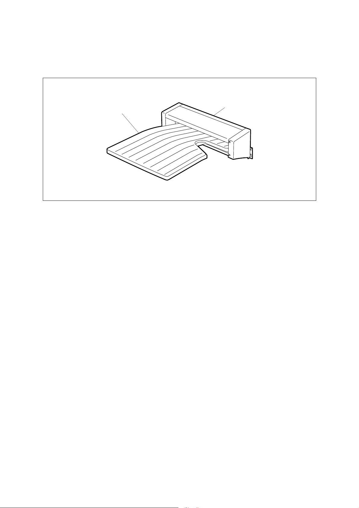
2.1 Names of Various Components
JSP tray
JSP open cover
JSP 02-01-01
October 2000 © TOSHIBA TEC 2 - 1 MJ-5001 OUTLINE
Page 6
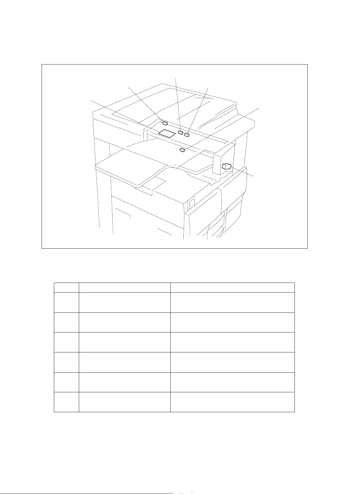
2.2 Layout of Electrical Parts
SW1
JSP (PWA-F-JSP)
SEN2
SEN3
SEN1
SOL1
Symbols and functions of various devices
Symbol
SW1
JSPCOV-SW
Name
JSP cover open switch
SEN1
PF1-SEN
JSP stack sensor (Lower)
SEN2
PF2-SEN
JSP stack sensor (Upper)
SEN3
JSPFED-SEN
JSP paper jam sensor
SOL1
JSPGATE-SOL
JSP solenoid
JSP
PWA-F-JSP
JSP PWA
JSP 02-02-01
Function
Detects the open/close state of the cover during
jam processing, etc.
Detects the limit number of sheets in the lower
stacker.
Detects the limit number of sheets in the upper
stacker.
Detects the presence or absence of transport
paper.
Switches the transport path (flap).
PWA which relays the sensor signals and solenoid drive signals.
MJ-5001 OUTLINE 2 - 2 October 2000 © TOSHIBA TEC
Page 7
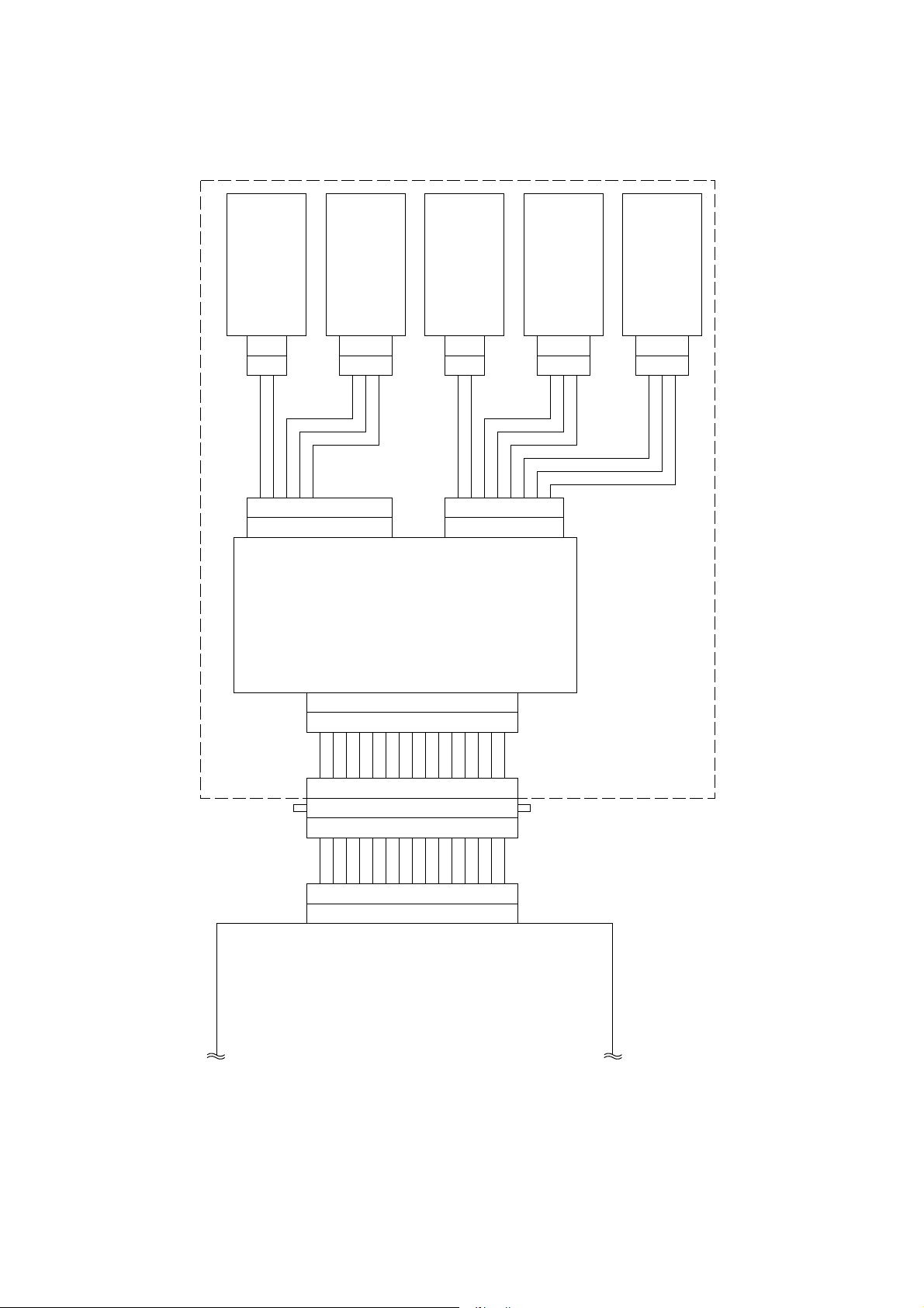
2.3 Harness Connection Diagram
JSP cover open switch
2
1
CN309
123456789
SG
SG
VCC
JCOS
CN261
FLS1ON
1514131211
NC
321
CN310
NCNCNC
(Lower)
JSP stack sensor
10
NC
987654312
10
JSP solenoid
JSP stack sensor
JSP paper jam sensor
(Upper)
2
1
CN305
1234567
SG
+24V
JSSON
CN262
JOB-JAM
VCC
CN308
SG
321
8
VCC
JFLS2
321
CN307
JSP PWA
JSP
1514131211
CN322
123456789
123456789
2
PG 3
CN41 CN260
OFFSET1
OFFSET2 1
987654312
10
4
6
+24V
JSSON 5
JOB/JAM 7
JFLS2ON
1011121315
10
8
10F/SELECT
JOB/SW 9
JCOSON
14
11
12
14+5V
12SG
15JPOSON
FLS1ON 13
JCONECT 11
Relay PWA
JSP 02-03-01
October 2000 © TOSHIBA TEC 2 - 3 MJ-5001 OUTLINE
Page 8

2.4 Board Assembl y
JSP 02-04-01 PPS2
MJ-5001 OUTLINE 2 - 4 October 2000 © TOSHIBA TEC
Page 9

3. OPERATIONAL DESCRIPTION
3.1 General Description
The JSP has a function to stack printed sheets of paper by putting them in the upper and lower stac k ers .
When fed to the JSP, printed paper can be stacked by putting it in the upper or lower stacker. Printed
sheets of paper are put in the upper or lower stacker b y changing the tr ansf er path with the flap.
3.2 Block Diagram
JSP
Relay
PWA
CN41
CN260
JSP
PWA
CN261CN262
JCOSON
JFLS1ON
JSSON
JOB-JAM
JFLS2ON
JSP cover open switch
JSP stack sensor (Lower)
JSP solenoid
JSP paper jam sensor
JSP stack sensor (Upper)
JSP 03-02-01
Four sensor switches and one solenoid are connected to the JSP PWA. The signals go through the RELAY
PWA as the y are and are connected to the MAIN PWA.
October 2000 © TOSHIBA TEC 3 - 1 MJ-5001 OPERATIONAL DESCRIPTION
Page 10

3.3 Detection of Abnormal Status
3.3.1 Cover open/close detection
When the JSP cover open s witch detects the open state of the co ver, the copier detects it and stops the
transport of paper.
3.3.2 Paper jam detection
The JSP has a sensor for detecting paper jamming for the upper stacker only. If the paper fed from the
copier is left stopped in the middle of the transport path for the upper stocker, the JSP paper jam sensor
detects paper jamming. The signal is at “High” le vel while the paper is passing. If the “High” le vel time is too
long, the copier will judge it to be paper jamming. The paper jamming can be cleared by opening the co v er
and removing the paper .
3.3.3 Stacker full detection
When the stackers are full of paper, a stacker full state is detected by the JSP stack sensor (Upper) f or the
upper stocker, and by the JSP stack sensor (Lower) for the lower stocker. The stacker full state can be
cleared by removing the paper from the stac k er . This detection is effectiv e only when the JSP is operating
so that no stacker full state occurs when the sensor is turned on while taking out the paper from the
stacker.
MJ-5001 OPERATIONAL DESCRIPTION 3 - 2 October 2000 © TOSHIBA TEC
Page 11

3.4 Flow Charts
Start button ON
Main motor ON
Polygon motor ON
Process unit fan motor high speed rotation
Development bias ON
Separation bias ON
Charge bias ON
Discharge lamp ON
Process system control Optical system control
Transfer system control
Retraction of carriage
Polygon motor
OK?
YES
Laser ON
Transfer bias ON
NO
Service call
"CA1"
Main motor
OK?
YES
Pickup clutch ON
Feed sensor
NO
Service call
"C01"
NG
Black shading
Exposure lamp ON
Stop of carriage
check
Transfer guide bias ON
Laser OFF
Transfer bias OFF
Transfer guide bias OFF
OK
Pickup clutch OFF
Registration roller
clutch ON
Registration roller
Paper jam
"E13"
Advance of carriage
White shading
Scanning of document
Stop of carriage
clutch OFF
Exposure lamp OFF
Retraction of carriage
Stop of carriage
NO
HSYNC
OK
YES
Remaining
copy count 0?
NO
Service call
"CA2"
NO
Remaining
copy count 0?
YES
Exit sensor
NG
Check 1
YES
Polygon motor OFF
OK
Paper jam
"E01"
End of optical
system control
Switching between
job separator upper
End of process
and lower gates
system control
A
October 2000 © TOSHIBA TEC 3 - 3 MJ-5001 OPERATIONAL DESCRIPTION
Page 12

A
Exit sensor
NG
Check 2
Paper jam
OK
Upper ejection
"E02"
NO
YES
JSP paper
NG
jam sensor
check
Paper jam
OK
Detected by
JSP stack sensor
(Upper)?
YES
Exit tray full
NO
Charge bias OFF
Main motor OFF
Development bias OFF
Separation bias OFF
Discharge lamp OFF
Process unit fan motor low speed rotation
Detected by
JSP stack sensor
(Lower)?
NO
YES
Exit tray full
Standby
MJ-5001 OPERATIONAL DESCRIPTION 3 - 4 October 2000 © TOSHIBA TEC
Page 13

4. MECHANICAL DESCRIPTION
4.1 Paper Feed System
Upper stocker
Lower stocker
Pinch roller (Upper)
Feed roller (Upper)
Pinch roller (Lower)
Feed roller (Lower)
JSP 04-01-01 PPS2
4.2 Paper Feed
There are the following two paths for paper transport, upper and lower, as indicated b y the arro ws in the
figure above. When unloading from the lower side, the paper is driven b y the feed roller (lo wer) and stac ked
as it is (indicated by the solid line arrow). When unloading from the upper side, the solenoid is turned ON
to lower the flap as indicated by the dotted line so that the paper passes through the upper tr ansport path
and is driven by the feed roller (upper) before beings stacked (indicated by the dotted line arrow). Also,
when the solenoid is turned ON, the pinch roller (lower) is lifted to open the upward transport path, thereby
facilitating paper passing.
4.3 Flap
The flap is driven by the JSP solenoid. Usually, when unloading the paper from the lower side, the flap is
lifted up by the spring so that the paper is stacked on the low er side (solenoid OFF). When unloading the
paper from the upper side, the JSP solenoid is driven to draw the plunger into the solenoid and lo wer the
flap so that the paper is fed to the upper transport path.
JSP solenoid
Flap
JSP solenoid
Flap
Pinch roller (Lower)
JSP 04-03-01 PPS2
October 2000 © TOSHIBA TEC 4 - 1 MJ-5001 MECHANICAL DESCRIPTION
Page 14

4.4 Drive System
Upper stocker
Lower stocker
JSP 04-04-01 PPS2
Since there is no motor in the JSP, the drive mechanism is given driving force from the copier through the
gears to turn the feed rollers (upper/lower). When unloading the paper from either upper or lo wer side, the
drive mechanism is driven b y the gears of the copier but the gears on the copier side for connecting the
upper and lower feed rollers are separ ately provided f or the upper and low er sides.
When unloading the paper from the upper side, the drive input from the copier is transmitted from the gear
to the belt to turn the feed roller (upper). Also, when unloading the paper from the upper side, the pinch
roller (lower) mov es upward (part A).
When unloading the paper from the lower side, the drive mechanism receiv es driving f orce from the gear on
the same shaft as that for the e xit roller and driv es the f eed roller (lo w er) through the three gears .
MJ-5001 MECHANICAL DESCRIPTION 4 - 2 October 2000 © TOSHIBA TEC
Page 15

5. CIRCUIT DESCRIPTION
5.1 PWA Block Diagram
Relay
PWA
JSP PWA
1
2
3
4
5
6
7
8
CN260
9
10
11
12
13
14
15
+5V
SG
+24V
PG
JPOSON
JFLS1ON
JCONECT
F-SELECT
JOB-SW
JCOSON
JOB-JAM
JFLS2ON
JSSON
OFFSET1
OFFSET2
NC
NC
SG
SG
SG
SG
+5V
SG
+5V
+24V
SG
+5V
NC
NC
1
2
3
4
5
CN261
6
7
8
9
10
1
2
3
4
5
CN262
JSP cover open switch
JSP stack sensor
(Lower)
Not used
JSP solenoid
JSP paper jam sensor
6
SG
+5V
7
8
JSP stack sensor
(Upper)
JSP 05-01-01
The signals only pass through the JSP PWA.
JCONECT and F-SECRET connect to GND and JOB-SW is open. The OCT, finisher, etc. can be connected to the copier in addition to the JSP. Those signals are used to identify the option connected. A
combination of the signals indicates the type of an option connected to the copier.
October 2000 © TOSHIBA TEC 5 - 1 MJ-5001 CIRCUIT DESCRIPTION
Page 16

5.2 Meaning of Signals
Signal Name
JCOVON
FLS1ON
JFLS2
JOB-JAM
JSSON
Part Name
JSP cover open
switch
JSP stack
sensor (Lower)
JSP stack
sensor (Upper)
JSP paper jam
sensor
JSP solenoid
Functional Description
Detects the open/close
state of the cover during
jam processing, etc.
Detects the limit number of
sheets in the lower stacker.
Detects the limit number of
sheets in the upper
stacker.
Detects the presence or
absence of transport
paper.
Switches the transport path
(flap)
Status
High: Open
High: Paper present
Note
Push switch
Photo sensor
Photo sensor
Photo sensor
Plunger
solenoid
The JSP cover open switch detects the open or close state of the cover. A push switch is used for the
switch. The signal goes LOW when the cov er is closed, and HIGH when it is open.
The JSP stack sensor (Lower) detects the limit n umber of sheets in the lo w er stacker . A photo sensor is
used for the sensor. When the stac ked number of sheets increases, the detection arm rises to turn on the
sensor.
The JSP stack sensor (Upper) detects the limit number of sheets in the upper stacker. A photo sensor is
used for the sensor. When the stac ked number of sheets increases, the detection arm rises to turn on the
sensor.
The JSP paper jam sensor detects the presence or absence of paper in the upper transport path. A photo
sensor is used for the sensor. The signal goes HIGH while paper is passing over the sensor (paper
present), and LOW when no paper is present. If the paper present time (“High” le vel) does not change e v en
after a fixed time, paper jamming will be assumed.
The JSP solenoid switches the transfer path to control the flap. The solenoid is usually OFF where the
paper passes through the lower transport path before being stacked. For stacking paper in the upper
stocker, the OCT solenoid turns ON to lower the flap so that the paper passes through the transport path for
the upper stocker bef ore being stac k ed.
MJ-5001 CIRCUIT DESCRIPTION 5 - 2 October 2000 © TOSHIBA TEC
Page 17

5.3 Timing Charts
4.87s (5.86s)
2.58s (1.89s)
4.28s (3.99s)
3.25s (2.36s)
*1
2.56s (1.89s)
2.12s (1.56s)
21ms (18.6ms)
*1
1.60s (1.18s)
The values in brac k ets is for the DP2500 machine.
The values are data (reference v alues) applicab le when the A4 siz e paper is used.
*1 Also turns on when ejecting the paper (detected when it is ON for more than a fixed time).
Exit sensor
• Upper stacker
October 2000 © TOSHIBA TEC 5 - 3 MJ-5001 CIRCUIT DESCRIPTION
JSP solenoid
JSP stack
sensor (Upper)
JSP stack
sensor (Lower)
• Lower stacker
Exit sensor
JSP solenoid
JSP stack
sensor (Upper)
JSP stack
sensor (Lower)
JSP 05-03-01
Page 18

6. DISASSEMBLY AND REPLA CEMENT
[A] JSP tray
1. Release 4 hooks and remove JSP tray.
JSP tray
[B] JSP right cover
1. Loosen 2 screws and detach JSP right cov er.
291
Fig. 6-1
JSP right
cover
[C] Connector cover
1. Remove 2 scre ws and detach connector cov er.
Screw
292
Fig. 6-2
Connector cover
Screw
293
Fig. 6-3
October 2000 © TOSHIBA TEC 6 - 1 MJ-5001 DISASSEMBLY AND REPLACEMENT
Page 19

[D] JSP left cover
1. Remove JSP tray. (See Fig. 6-1)
2. Detach JSP right cover. (See Fig. 6-2)
3. Detach connector cov er. (See Fig. 6-3)
4. Detach the ground wire and the connector .
Ground wire
5. If an ADU (MD-0101) is attached to the copier,
open it.
6. Open side cov er.
7. Open exit cover.
8. Remove one screw, release one hook, and remove JSP.
Fig. 6-4
Fig. 6-5
Connector
Hook
294
017
JSP
Screw
295
Fig. 6-6
9. Loosen 3 screws, detach the harness, and detach JSP left cover.
Screw
Ground
wire
JSP left cover
Harness
296
Fig. 6-7
MJ-5001 DISASSEMBLY AND REPLACEMENT 6 - 2 October 2000 © TOSHIBA TEC
Page 20

[E] JSP Top Cover
1. Remov e JSP. (See Fig. 6-1 and 6-6)
2. Detach JSP left cover. (See Fig. 6-7)
3. Remove 2 screws and detach JSP top cover.
Screw
JSP top cover
Screw
297
Fig. 6-8
[F] JSP PWA
1. Remov e JSP. (See Fig. 6-1 and 6-6)
2. Detach JSP left cover. (See Fig. 6-7)
3. Detach JSP top cover. (See Fig. 6-8)
4. Detach all the connectors, release 3 locking supports, and remove JSP PWA.
5. Remove locking supports.
[G] Solenoid/Solenoid Arms
1. Remov e JSP. (See Fig. 6-1 and 6-6)
2. Detach JSP top cover. (See Fig. 6-8)
3. Detach spring and detach the connector.
JSP PWA
Locking support
298
Fig. 6-9
Spring
Connector
299
Fig. 6-10
4. Remove 2 screws, and remove solenoid.
5. Remov e solenoid arm 2 from plunger.
6. Remove the E-ring and detach the solenoid arm
1.
Note: For adjustment when installing solenoid, the
Marking
Screw
Pin
Solenoid
arm 1
E-ring
Solenoid
arm 2
edge of solenoid must be in the center of
the marking.
Solenoid
Plunger
300
Fig. 6-11
October 2000 © TOSHIBA TEC 6 - 3 MJ-5001 DISASSEMBLY AND REPLACEMENT
Page 21

[H] JSP open cover assembly
1. Remov e JSP. (See Fig. 6-1 and 6-6)
2. Remove one screw and remove hinge.
3. Release one hook and detach JSP open cover
assembly.
Hinge
[I] JSP Roller
1. Remov e JSP. (See Fig. 6-1 and 6-6)
2. Detach JSP left cov er. (See Fig. 6-7)
3. Remove 2 screws and detach the drive gear
plate.
4. Remove drive gear and timing belt 240.
5. Detach stop ring, and remove pulley and bushing.
6. Remove one stop ring, remove 2 bushings on
both sides, and detach the JSP upper roller .
Screw
Pin
Stop ring
Screw
Bushing
Fig. 6-12
Pulley
Timing belt 240
Drive gear
Drive gear plate
Fig. 6-13
JSP open cover
assembly
301
Pin
302
Bushing
JSP upper roller
Stop ring
303
Fig. 6-14
[J] JSP Lower Roller
1. Remov e JSP. (See Fig. 6-1 and 6-6)
2. Detach JSP open cover assembly.
(See Fig. 6-12)
3. Remove 2 screws and detach the guide plate.
Guide plate
Screw
Screw
303-1
Fig. 6-15
MJ-5001 DISASSEMBLY AND REPLACEMENT 6 - 4 October 2000 © TOSHIBA TEC
Page 22

4. Remove one stop ring and detach the JSP lower
roller assembly.
5. Remove 2 bushings on both sides and remove
the E-ring. Then detach the JSP lower roller gear .
Bushing
Stop ring
E-ring
JSP lower roller assembly
Bushing
Pin
JSP lower roller gear
Fig. 6-16
303-2
October 2000 © TOSHIBA TEC 6 - 5 MJ-5001 DISASSEMBLY AND REPLACEMENT
Page 23

1-1, KANDA NISHIKI-CHO, CHIYODA-KU, TOKYO, 101-8842 J APAN
 Loading...