

Page 1

SERVICE MANUAL
FINISHER
MJ-1103/1104
Model: MJ-1103/1104
Publish Date: August 2008
File No. SME070020C0
R070921E5300-TTEC
Ver03_2009-06
Page 2

Trademarks
• Molykote is a registered trademark of Dow Corning Corporation.
• Other company names and product names in this manual are the trademarks of their respective
companies.
© 2008, 2009 TOSHIBA TEC CORPORATION All rights reserved
Under the copyright laws, this manual cannot be reproduced in any form without prior written permission
of TOSHIBA TEC CORPORATION. No patent liability is assumed, however, with respect to the use of the
information contained herein.
Page 3

General Precautions for Installation/Servicing/Maintenance
for MJ-1103/1104
The installation and service should be done by a qualified service
technician.
1. When installing the MJ-1103/1104, be sure to follow the instructions described in the “Unpacking/
Set-Up Procedure for the MJ-1103/1104”.
2. The MJ-1103/1104 should be installed by an authorized/qualified person.
3. The Finisher is quite heavy; MJ-1103 weighs approximately 40 kg (88.19 lb.) and MJ-1104 weighs
approximately 70 kg (154.32 lb.), therefore pay full attention when handling it.
4. Before starting installation, servicing or maintenance work, be sure to turn OFF and unplug the
equipment first.
5. The equipment shall be installed near the socket outlet and shall be accessible.
6. Be sure to fix and plug in the power cable securely after the installation so that no one trips over it.
7. When selecting the installation site, avoid placing the finisher / hole punch unit and equipment on
different levels or inclined floors.
8. The equipment shall be installed near the socket outlet and shall be easily accessible.
9. When the MJ-1103/1104 is removed from the equipment due to malfunction or other reasons but no
substitute machine is to be installed, be sure to remove all the installation hardware from the equipment as well.
10.When servicing or maintaining the MJ-1103/1104, be careful about the rotating or operation sections
such as gears, pulleys, sprockets, cams, belts, etc.
11.When parts are disassembled, reassembly is basically the reverse of disassembly unless otherwise
noted in this manual or other related materials.
Be careful not to reassemble small parts such as screws, washers, pins, E-rings, toothed washers,
harnesses to the wrong places.
12.Basically, the machine should not be operated with any parts removed or disassembled.
13.Delicate parts for preventing safety hazard problems (such as switches, sensors, etc. if any) should
be handled/installed/adjusted correctly.
14.Use suitable measuring instruments and tools.
15.During servicing or maintenance work, be sure to check the serial No.plate and other cautionary
labels (if any) to see if they are clean and firmly fixed.
If not, take appropriate actions.
16.The PC board must be stored in antistatic envelope and handled carefully using a wristband,
because the ICs on it may be damaged due to static electricity.
Before using the wrist band, pull out the power cable plug of the equipment and make sure that
there is no uninsulated charged objects in the vicinity.
Page 4

17.For the recovery and disposal of used MJ-1103/1104, consumable parts and packing materials, follow the relevant local regulations/rules.
18.After completing installation, servicing and maintenance of the MJ-1103/1104, return the MJ-1103/
1104 to its original state, and check operation.
19.When the equipment is used after the option is removed, be sure to install the parts or the covers
which have been taken off so that the inside of the equipment is not exposed.
20.When you move the finisher, do not move it in the direction of the arrow as shown in the figure below
otherwise it might topple over.
21.Unplug the power cable and clean the area around the prongs of the plug and socket outlet once a
year or more. A fire may occur when dust lies on this area.
Page 5

CONTENTS
MJ-1103/1104
1. SPECIFICATIONS, ACCESSORY AND CONSUMABLES.......................................... 1-1
1.1 Specifications....................................................................................................................... 1-1
1.1.1 Finisher section (Common for MJ-1103/1104) ....................................................... 1-2
1.1.2 Saddle stitch section (MJ-1104) ............................................................................. 1-5
1.2 Accessory ............................................................................................................................ 1-6
1.3 Consumables....................................................................................................................... 1-6
2. GENERAL DESCRIPTION............................................................................................ 2-1
2.1 Main Components................................................................................................................ 2-1
2.2 Sectional View ..................................................................................................................... 2-2
2.3 Electric Parts Layout............................................................................................................ 2-7
2.4 Symbols and Functions of Various Components................................................................. 2-9
2.5 Diagram of Signal Blocks................................................................................................... 2-13
2.6 Description of Interface Signals ......................................................................................... 2-15
3. DESCRIPTION OF OPERATIONS ............................................................................... 3-1
3.1 Basic Operations ................................................................................................................. 3-1
3.1.1 GENERAL DESCRIPTION..................................................................................... 3-1
3.1.2 Junction Box........................................................................................................... 3-3
3.1.3 Simple Stack Mode ................................................................................................ 3-4
3.1.4 Job offset stack mode / Staple stack mode............................................................ 3-9
3.1.5 Operation in the saddle stitch section .................................................................. 3-14
3.2 Flow Chart ......................................................................................................................... 3-20
3.3 Description Of Circuit......................................................................................................... 3-23
3.3.1 Finishier section ................................................................................................... 3-23
3.3.2 Saddle section...................................................................................................... 3-35
4. DISASSEMBLY AND INSTALLATION ........................................................................ 4-1
4.1 Covers ................................................................................................................................ 4-1
4.2 Units (Finisher section) ...................................................................................................... 4-13
4.3 Units (Saddle section: MJ-1104) ....................................................................................... 4-26
4.4 Rollers (Finisher section)...................................................................................................4-38
4.5 Rollers (Saddle section: MJ-1104).................................................................................... 4-58
4.6 Motor (Finisher section).....................................................................................................4-64
4.7 Motor (Saddle section: MJ-1104)...................................................................................... 4-74
4.8 Solenoid............................................................................................................................. 4-79
4.9 Sensors / Switches (Finisher section)................................................................................ 4-91
4.10 Sensors / Switches (Saddle section: MJ-1104) ............................................................... 4-110
4.11 PC Boards / Discharge Brush.......................................................................................... 4-120
4.12 Procedure for lowering the movable tray ......................................................................... 4-124
5. ADJUSTMENTS............................................................................................................ 5-1
5.1 Adjusting the Alignment Position ......................................................................................... 5-1
5.2 Adjusting the Stapling Position ............................................................................................ 5-4
5.3 Stapling/folding position adjustment in saddle unit .............................................................. 5-6
5.3.1 Folding position adjustment.................................................................................... 5-8
5.3.2 Stapling position adjustment ................................................................................ 5-10
5.4 Saddle Stitch Skew Adjustment......................................................................................... 5-12
6. TROUBLESHOOTING .................................................................................................. 6-1
6.1 Paper Transport Jam........................................................................................................... 6-1
6.1.1 Paper jam in entrance section................................................................................ 6-1
6.1.2 Paper jam in buffer unit-1 ....................................................................................... 6-3
6.1.3 Paper jam in buffer unit-2 ....................................................................................... 6-5
© 2008, 2009 TOSHIBA TEC CORPORATION All rights reserved MJ-1103/1104
1
CONTENTS
Page 6

6.1.4 Paper jam in finishing tray section.......................................................................... 6-7
6.1.5 Paper jam in movable tray section ....................................................................... 6-12
6.1.6 Cover open jam .................................................................................................... 6-13
6.2 Paper Transport Jam in Saddle Stitch Section (MJ-1104)................................................. 6-15
6.2.1 Paper jam in Saddle Stitch Finisher transport section.......................................... 6-15
6.2.2 Paper jam in side alignment section..................................................................... 6-19
6.2.3 Paper jam in stack transport section .................................................................... 6-19
6.2.4 Paper jam in folding section ................................................................................. 6-21
6.2.5 Paper jam in additional folding section................................................................. 6-22
6.3 Other Errors....................................................................................................................... 6-23
6.3.1 Stapler related error ............................................................................................. 6-23
6.3.2 Saddle Stitch Finisher stapler related error (MJ-1104)......................................... 6-25
6.3.3 Communication Related Error .............................................................................. 6-26
6.3.4 Memory error........................................................................................................ 6-27
7. PREVENTIVE MAINTENANCE (PM) / FIRMWARE UPDATE ..................................... 7-1
7.1 Maintenance and Inspection Points..................................................................................... 7-1
7.2 Firmware Update ................................................................................................................. 7-6
7.2.1 Update of CNV board ............................................................................................. 7-6
7.2.2 Update of FIN board............................................................................................... 7-8
7.2.3 Update of SDL board............................................................................................ 7-10
8. ELECTRIC CIRCUIT ..................................................................................................... 8-1
8.1 Harness Diagram................................................................................................................. 8-1
8.2 Circuit Diagram .................................................................................................................... 8-5
8.3 PC board ........................................................................................................................... 8-32
MJ-1103/1104 © 2008, 2009 TOSHIBA TEC CORPORATION All rights reserved
CONTENTS
2
Page 7

1. SPECIFICATIONS, ACCESSORY AND CONSUMABLES
1.1 Specifications
• Product Type
MJ-1103: Console Finisher (2 trays)
MJ-1104: Console Saddle Stitch Finisher (3 trays)
• Paper Stacking Device Stationary Tray or Movable Tray, Saddle Tray (MJ-1104)
• Paper Size A3, A4, A4-R, A5, A5-R, A6-R, B4, B5, B5-R, FOLIO, A3 wide,
LD, LG, LT, LT-R, ST, ST-R, COMPUTER, 13”LG, 8.5”SQ,
8K, 16K, 16K-R
1
• Paper Basis Weight 64 - 300g/m
• Stacking Mode Simple, Job Offset, Staple and composite, Center-binding (MJ-1104)
• Dimensions with Sub-tray put in: W 617 x D 603 x H 1,085 (mm)
with Sub-tray drawn out: W 750 x D 603 x H 1,085 (mm)
• Gross Weight
MJ-1103: Approximately 40kg (88.19 lb)
MJ-1104: Approximately 70kg (154.32 lb)
• Power Supply DC24V±10% and DC5V±5% supplied from the main equipment.
• Power Consumption DC24V Average 3.7A or less
5V 1.0A or less
2
© 2008, 2009 TOSHIBA TEC CORPORATION All rights reserved MJ-1103/1104
1 - 1
SPECIFICATIONS, ACCESSORY AND CONSUMABLES
Page 8
1.1.1 Finisher section (Common for MJ-1103/1104)
• Stacking Type Facedown
• Stacking Height with
Stationary Tray
Paper Size Stacking
A4, B5, LT, A5-R, ST-R, 8.5”SQ, 16K,
Postcard, A4-TAB, LT-TAB, A6-R
A3, A4-R, B4, FOLIO, LD, LG, LT-R,
COMPUTER, B5-R, 13”LG, 8K, 16K-R,
A3 wide, 12” x 18”, 13” x 19”,
320 x 450mm, 320 x460mm, Universal
Height
36.75mm 250 225 190
18.4mm 125 112 95
The maximum stacking height is 18.4 mm for mixed size paper.
ÅgFullÅh status is defined as when the stationary tray paper-full sensor (S18) detected the full status of paper in the size available for feeding.
Movable tray (in the job offset stack mode)
Paper Size Stacking
A4, B5, LT, 8.5”SQ, 16K, A4-TAB, LT-TAB 350mm 3,000 2,700 2,300
A3, A4-R, B4, FOLIO, LD, LG, LT-R,
COMPUTER, 13”LG, 8K, 16K-R,
A3 wide,12" x 18"
ST-R, A5-R, B5-R, A6-R, Postcard,
Universal
Height
80g/m
175mm 1,500 1,350 1,150
- 500 500 500
Number of sheets (reference)
64 - 80g/m
Paper
2
81 - 90g/m2
Paper
Number of sheets (reference)
2
Paper 90g/m2 Paper 105g/m2
91 - 105g/m2
Paper
Paper
The maximum stacking height is 175 mm for mixed size paper. However, ST-R, A5-R, B5-R, A6-R
and non-standard sizes are not acceptable for mixed size paper.
ÅgFullÅh status is defined as when the number of paper whose maximum stacking height is 350
mm has reached 3,000 or when the number of paper in other sizes has reached 1,500.
The maximum number of sheets acceptable is 1,500 for mixed size paper. However, ST-R, A5-R,
B5-R, A6-R and non-standard sizes are not acceptable for mixed size paper.
Movable tray (in the staple stack mode)
Paper Size
Front/Rear Single Position
Stapling
A4, B5, LT, A4-TAB, LT-TAB A paper-full status is detected
either when the number of
stacks reaches 100 or when
the number of sheets reaches
2,000.
A3, A4-R, B4, FOLIO, LD, LG, LT-R,
COMPUTER, 13”LG, 8K, 16K, 8.5”SQ
MJ-1103/1104 © 2008, 2009 TOSHIBA TEC CORPORATION All rights reserved
SPECIFICATIONS, ACCESSORY AND CONSUMABLES
A paper-full status is detected
either when the number of
stacks reaches 50 or when
the number of sheets reaches
1,000.
1 - 2
Stacking Height
64 - 105 g/m
2
(reference)
Two-Position Stapling
A paper-full status is detected
either when the number of
stacks reaches 150 or when
the number of sheets reaches
2,000.
A paper-full status is detected
either when the number of
stacks reaches 75 or when
the number of sheets reaches
1,000.
Page 9
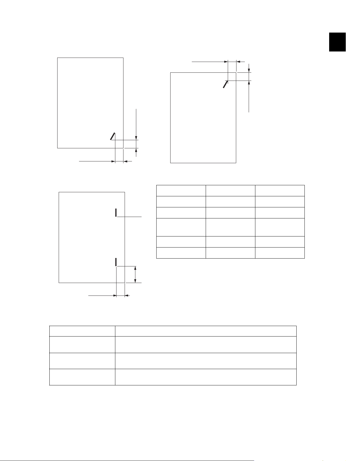
• Stapling Position
4.5 ±3.0 mm
6 ±3.5 mm
4.5 ±3.0 mm
6 ±3.5 mm
A
B
5 ±3.0 mm
Front single position Rear single position
Fig. 1-1 Fig. 1-2
Two-Position Stapling
Paper Size A B
A3, A4, A4-TAB 81.0 ±3.5mm 205.0 ±3.5mm
1
• Paper Size for stapling
Stapling Position Paper Size
Front Single A3, A4, A4-R, B4, B5, FOLIO, LD, LG, LT, LT-R, COMPUTER, 13”LG,
Rear Single A3, A4, A4-R, B4, B5, FOLIO, LD, LG, LT, LT-R, COMPUTER, 13”LG,
Two-Positions A3, A4, A4-R, B4, B5, FOLIO, LD, LG, LT, LT-R, COMPUTER, A4-TAB,
Fig. 1-3
A4-R, FOLIO 37.5 ±3.5mm 161.5 ±3.5mm
B4, B5, COMPUTER
LD, LT, LT-TAB 72.0 ±3.5mm 196.0 ±3.5mm
LT-R, LG 40.5 ±3.5mm 164.5 ±3.5mm
8.5”SQ, 8K, 16K, A4-TAB, LT-TAB
8.5”SQ, 8K, 16K, A4-TAB, LT-TAB
LT-TAB
61.0 ±3.5mm 185.0 ±3.5mm
Stapling is not available for paper in sizes other than the above.
© 2008, 2009 TOSHIBA TEC CORPORATION All rights reserved MJ-1103/1104
SPECIFICATIONS, ACCESSORY AND CONSUMABLES
1 - 3
Page 10

• Paper Basis Weight for stapling 64 - 105g/m
2
• The number of Stapleable Sheet
Paper Size
64 - 80g/m
Paper
2
81 - 90g/m
Paper
A4, B5, LT, 8.5”SQ, 16K 50 50 30
2
91 - 105g/m
Paper
2
A3, A4-R, B4, FOLIO, LD, LG, LT-R,
30 30 15
COMPUTER, 13”LG, 8K
Maximum number of sheets acceptable for stapling:
A4, B5, LT, 8.5”SQ, 16K, A4-TAB, LT-TAB - 50 sheets
A3, A4-R, B4, FOLIO, LD, LG, LT-R, COMP, 13”LG, 8K - 30 sheets
* Two sheets of cover sheet (200-256 g/m2) can be included.
• Staple Loading exclusive cartridge (5,000 staples)
• Manual Stapling available
MJ-1103/1104 © 2008, 2009 TOSHIBA TEC CORPORATION All rights reserved
SPECIFICATIONS, ACCESSORY AND CONSUMABLES
1 - 4
Page 11
1.1.2 Saddle stitch section (MJ-1104)
• Binding method Center-binding only
• Paper Size A3, B4, A4-R, LD, LG, LT-R
• Number of sheets available for stapling
64 - 80g/m2 Paper 81 - 90g/m2 Paper 91 - 105g/m2 Paper
15 15 10
* One sheet of cover sheet (200-256 g/m2) can be included.
1
• Paper Basis Weight for stapling 64 - 105g/m
2
• Staple Loading exclusive cartridge (2,000 staples)
• Exiting paper not folded Not available
• Exiting paper not stapled Exited when only one sheet in the stack is unstapled
• Stapling interval 120 mm
• Number of stacks available
No thick paper cover included
Paper Size
Under 5 sheets/books 50 40
Under 10 sheets/books 30 25
Under 155 sheets/books 25 -
64 - 90g/m
2
Paper 91 - 105g/m2 Paper
Thick paper cover included
Paper Size
Under 5 sheets/books 50 30
64 - 90g/m2 Paper 91 - 105g/m2 Paper
Under 10 sheets/books 15 15
Under 155 sheets/books 10 -
A paper-full status is detected when the number of stacks reaches the values shown below.
Paper Size No thick paper cover included Thick paper cover included
Under 5 sheets/books 50 50
Under 10 sheets/books 30 15
Under 155 sheets/books 25 10
© 2008, 2009 TOSHIBA TEC CORPORATION All rights reserved MJ-1103/1104
1 - 5
SPECIFICATIONS, ACCESSORY AND CONSUMABLES
Page 12

1.2 Accessory
Unpacking Instruction 1set 1set
Movable tray 1pc 1pc
Connect rail plate 1pc 1pc
Connect rail 1pc 1pc
Connect plate 1pc 1pc
Joint plate 1pc 1pc
Position plate 1pc 1pc
Connector cover 1pc 1pc
Saddle tray - 1pc
Slide tray - 1pc
Leveling arm - 1pc
Screw: TBID M4x8 6pcs 6pcs
Screw: TBID M4x12 4pcs 4pcs
Screw: M3x8 5pcs 5pcs
MJ-1103 MJ-1104
Screw: M3x12 - 2pcs
Screw: M3x6 - 2pcs
Harness clamp 1pc 1pc
1.3 Consumables
• Staple cartridge for the Finisher section
exclusive cartridge (STAPLE-2400: 5,000staples X 3 cartridges /box)
• Staple cartridge for the saddle stitch section (MJ-1104)
exclusive cartridge (STAPLE-3100: 2,000staples X 4 cartridges /box)
MJ-1103/1104 © 2008, 2009 TOSHIBA TEC CORPORATION All rights reserved
SPECIFICATIONS, ACCESSORY AND CONSUMABLES
1 - 6
Page 13
2. GENERAL DESCRIPTION
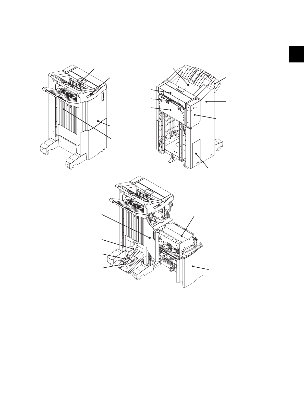
Front upper cover
Stationary Tray
Movable Tray
Jam access lever
MJ-1103
MJ-1104
Staple bottoms
Rght upper cover
Relay Guide
Rear cover
Saddle Tray
Slide Tray
Leveling arm
Grate-shaped guide
Rght cover
PC board access cover
Saddle access cover
Saddle unit
Front cover
Front lower cover
2.1 Main Components
2
Fig. 2-1
© 2008, 2009 TOSHIBA TEC CORPORATION All rights reserved MJ-1103/1104
2 - 1
GENERAL DESCRIPTION
Page 14
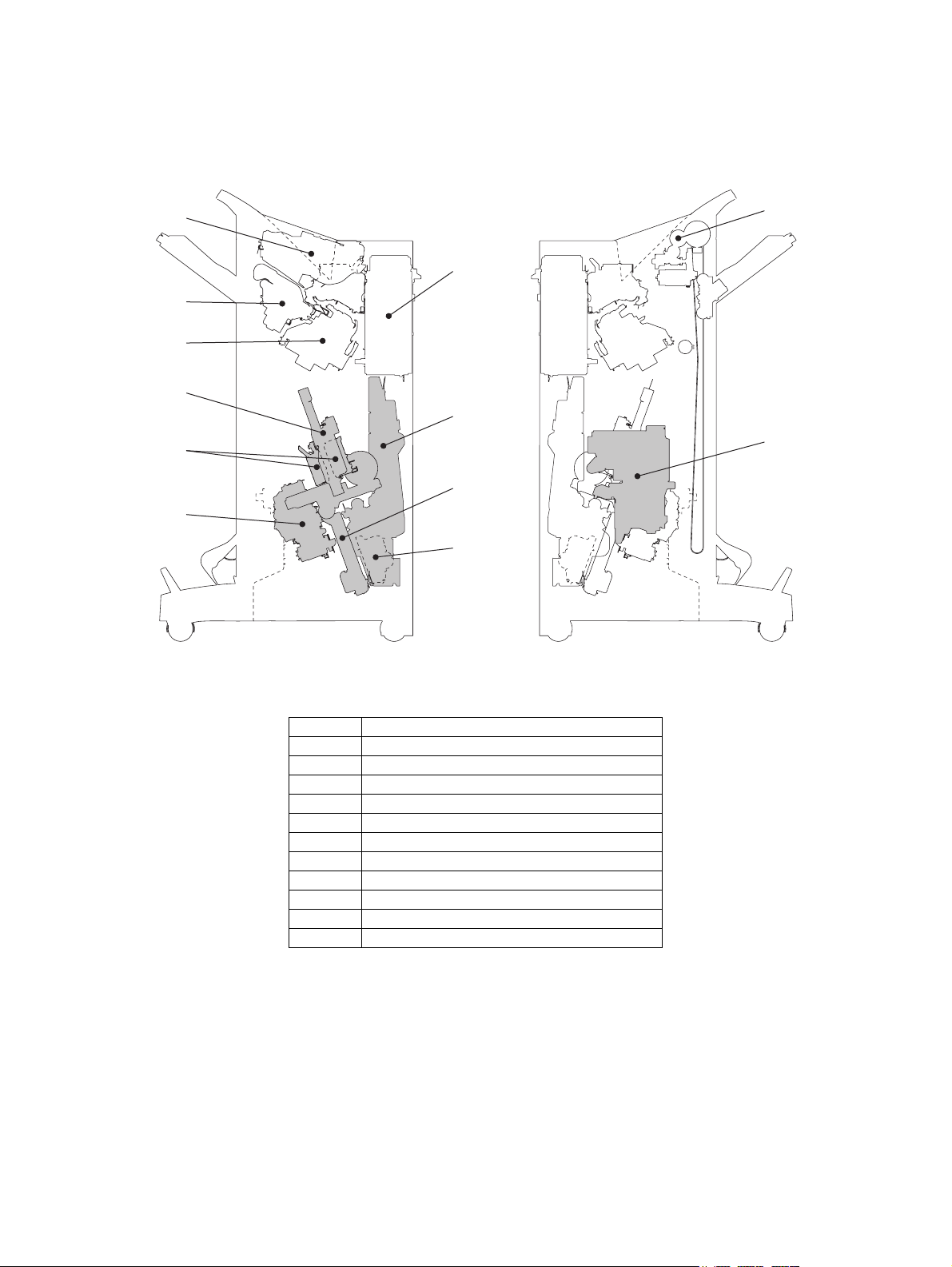
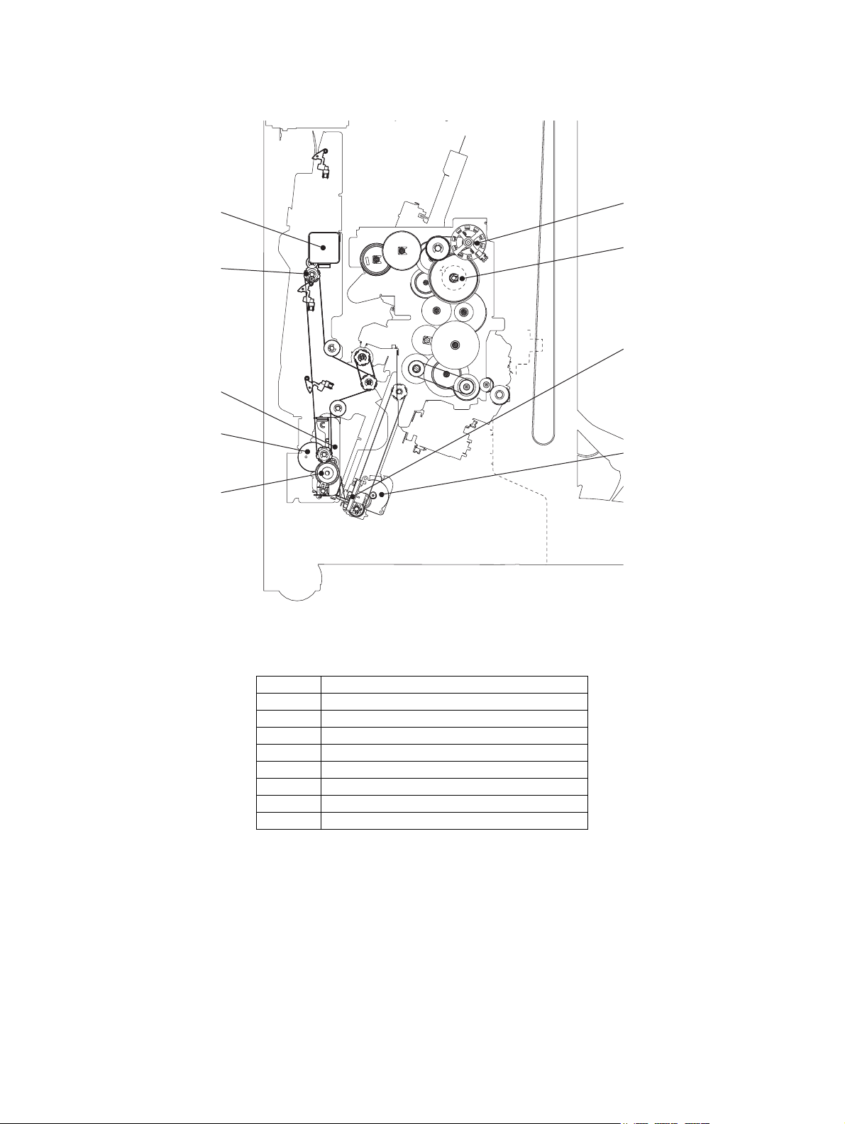
2.2 Sectional View
6
7
8
1
5
12
2
3
4
9
10
11
[A] Units
Fig. 2-2
1 Junction box unit
2 Buffer unit
3 Finishing tray unit
4Stapler
5 Movable tray shift motor unit
6 Switchback unit
7 Stacker unit (MJ-1104)
8 Paper holding unit (MJ-1104)
9 Side alignment unit (MJ-1104)
10 Saddle stapler unit (MJ-1104)
11 Folding drive unit (MJ-1104)
12 EFS unit (MJ-1104)
MJ-1103/1104 © 2008, 2009 TOSHIBA TEC CORPORATION All rights reserved
GENERAL DESCRIPTION
2 - 2
Page 15
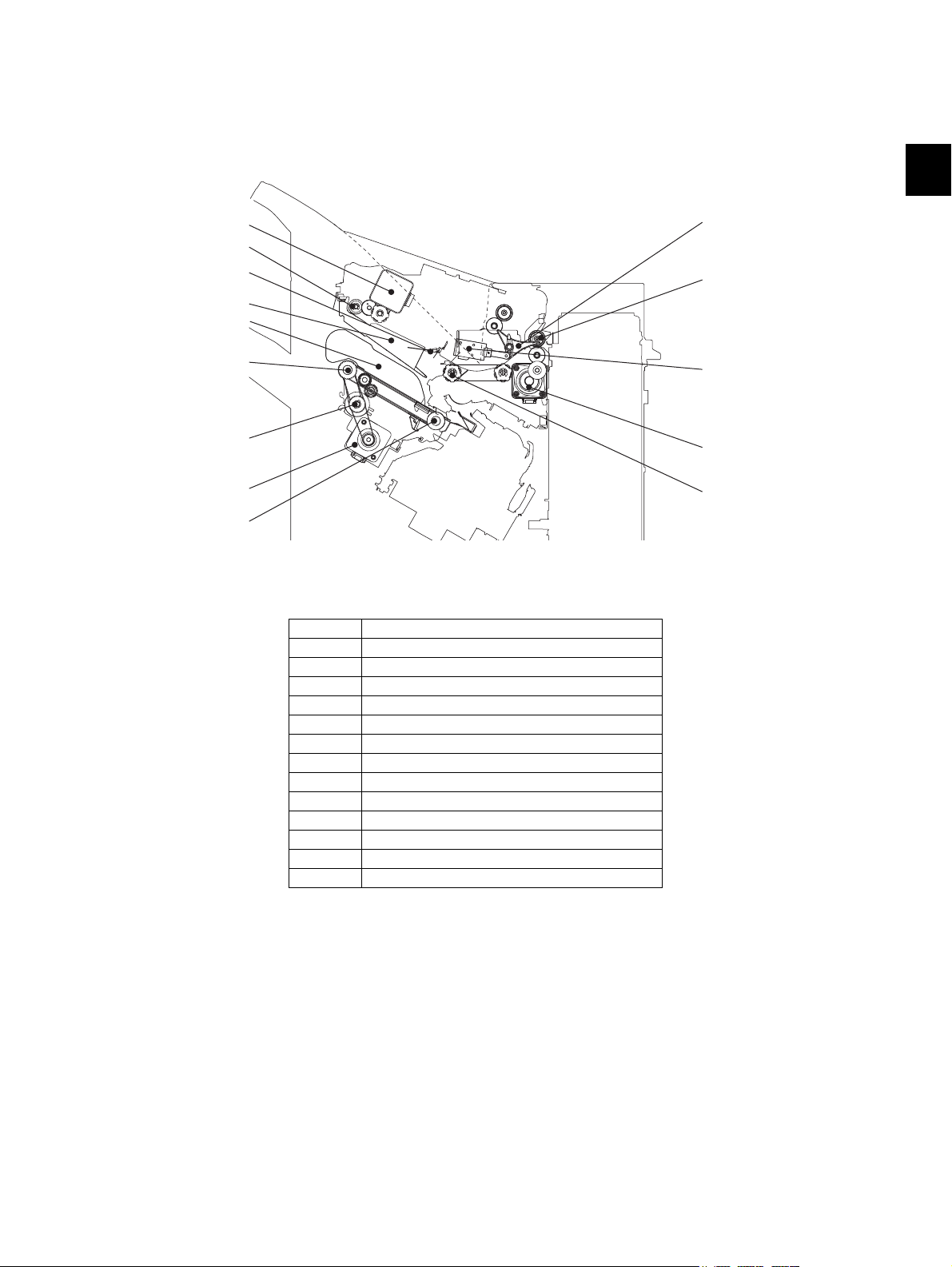
[B] Finisher section
M4
3
4
5
6
CLT2
9
M1
8
7
SOL2
M8
2
1
[B-1] Front side view
2
Fig. 2-3
1 Buffer roller
2 Paper pusher plate
3 Buffer tray
4 Finishing tray
5 Stack transport roller-2
6 Stack transport roller-1
7 Gate flap
8 Entrance roller
9Exit roller
M1 Entrance motor
M4 Buffer roller drive motor
M8 Stack transport motor
CLT2 Paper exit guide clutch
SOL2 Gate solenoid
© 2008, 2009 TOSHIBA TEC CORPORATION All rights reserved MJ-1103/1104
2 - 3
GENERAL DESCRIPTION
Page 16
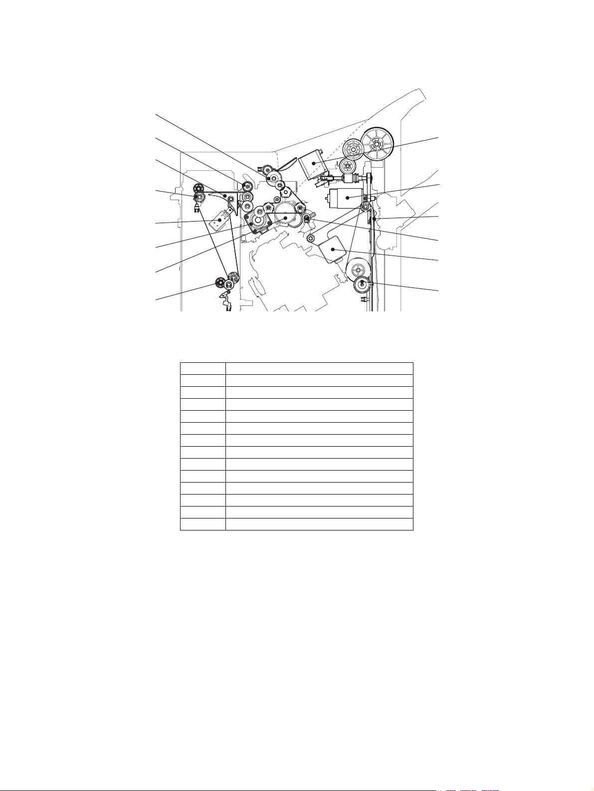
[B-2] Rear side view
M2
M12
6
M7
CLT1
2
3
SOL5
4
5
1
7
M11
M3
Fig. 2-4
1 Stationary tray roller
2 Entrance roller
3 Flapper
4 Feeding roller
5 Junction roller
6 Shutter
7 Paddle
M2 Buffer tray guide motor
M3 Paddle motor
M7 Transport motor
M11 Exit motor
M12 Movable tray shift motor
CLT1 Shutter clutch
SOL5 Transport path switching solenoid
MJ-1103/1104 © 2008, 2009 TOSHIBA TEC CORPORATION All rights reserved
GENERAL DESCRIPTION
2 - 4
Page 17
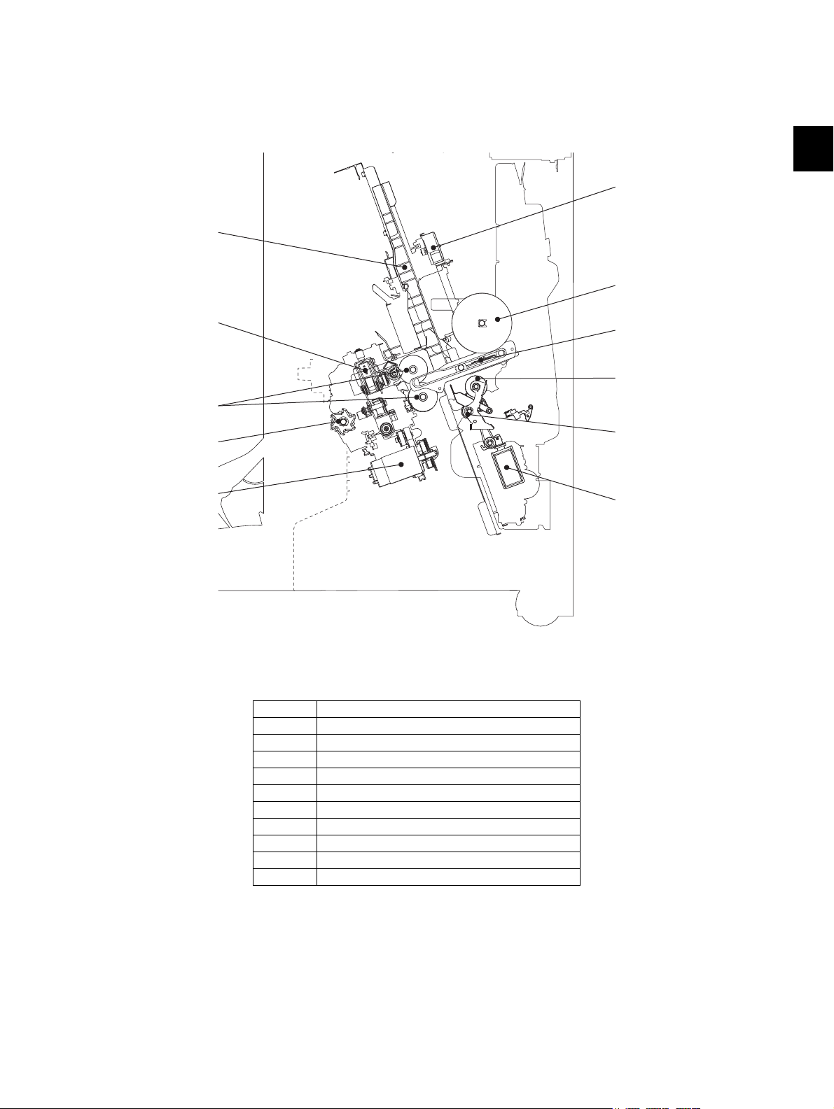
[C] Saddle section
1
M15
5
6
7
8
SOL6
3
2
4
M20
[C-1] Front side view
2
Fig. 2-5
1Jog
2 Additional folding carrier
3 Folding roller
4 Saddle exit roller
5 Folding blade cam
6 Folding blade
7 Assisting roller
8 Ejecting roller
M15 Side alignment motor
M20 Additional folding motor
SOL6 Assisting roller solenoid
© 2008, 2009 TOSHIBA TEC CORPORATION All rights reserved MJ-1103/1104
2 - 5
GENERAL DESCRIPTION
Page 18
[C-2] Rear side view
M16
M14
4
CLT3
M17
1
3
2
CLT4
Fig. 2-6
1 Transport roller
2 Paper holding damper
3 Paper holding cam
4 Stacker carrier
M14 Stacker motor
M16 saddle transport motor
M17 Folding motor
CLT3 Folding blade clutch
CLT4 Paper holding clutch
MJ-1103/1104 © 2008, 2009 TOSHIBA TEC CORPORATION All rights reserved
GENERAL DESCRIPTION
2 - 6
Page 19
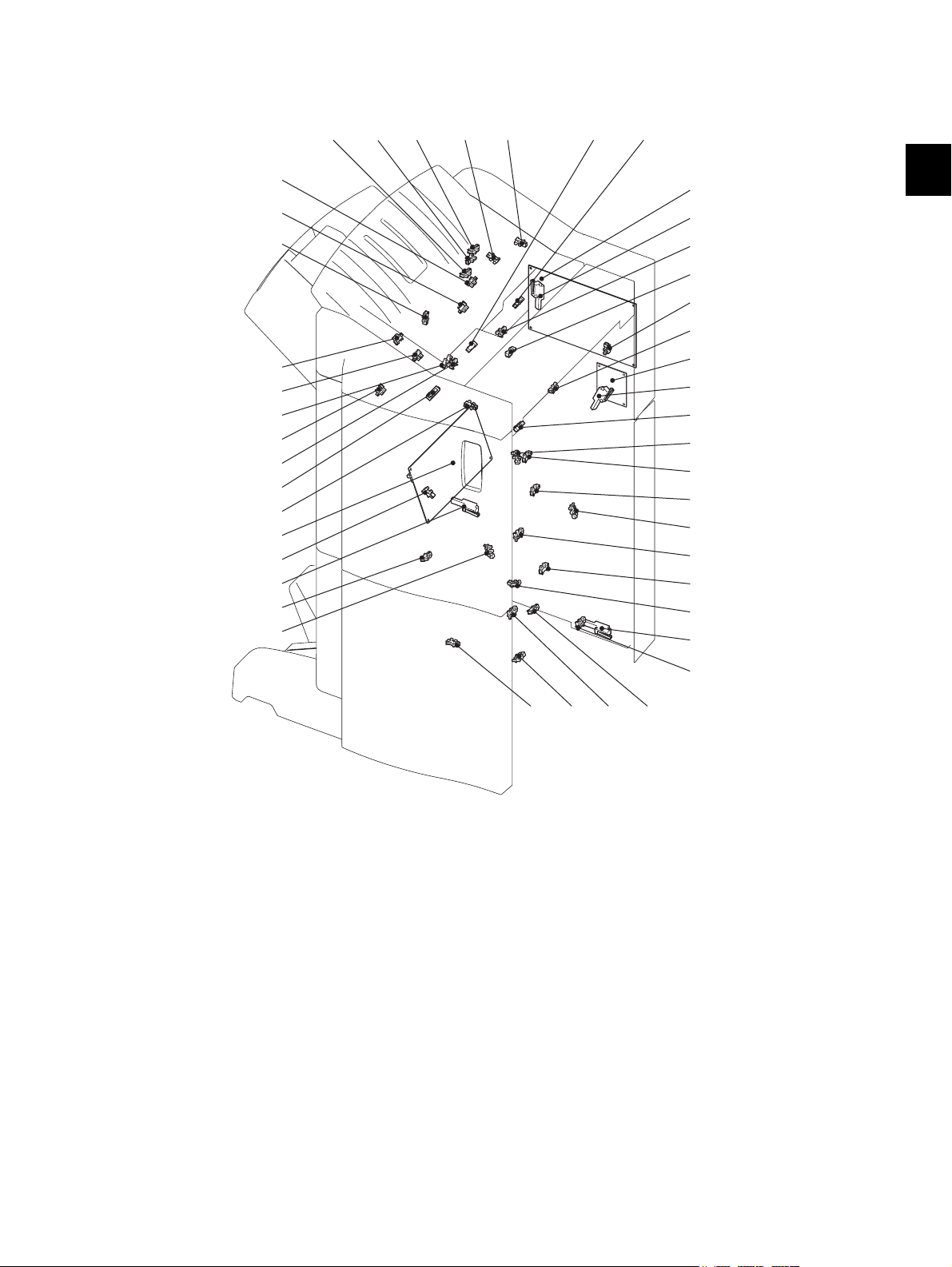
2.3 Electric Parts Layout
S27
S35
S34
S36
SW5
S38
S41
S28
S42
SDL
S31
S39
S32
S29S33 S30
S15 S23S5S13S14 S3
SW2
S18
S1
S25
S26
I/F
SW4
S16
S8
S6
S17
S12
S7
S4
S9
S11
S10
SW3
SW1
S2
S22
FIN
2
Fig. 2-7
© 2008, 2009 TOSHIBA TEC CORPORATION All rights reserved MJ-1103/1104
GENERAL DESCRIPTION
2 - 7
Page 20
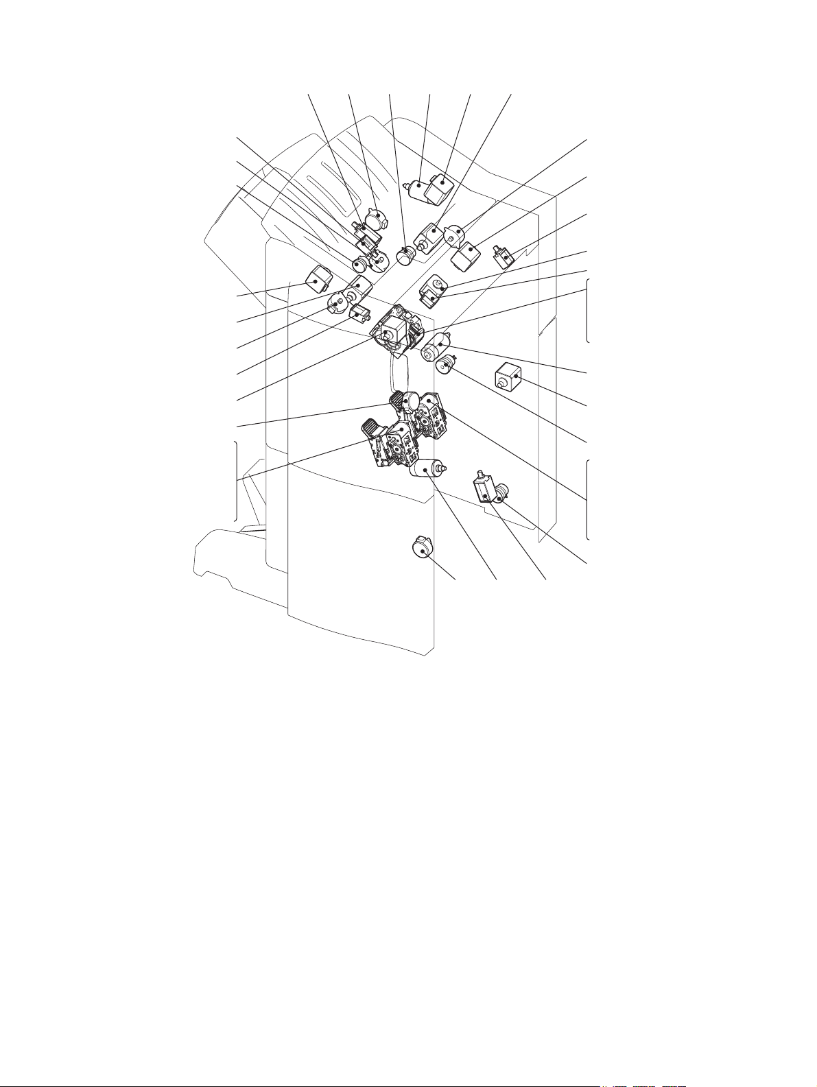
SOL2 M10 M2M12
M3
M7
M1
CLT2
M9
SOL1
SOL5
M16
M14 M20 SOL6
CLT4
CLT3
M13
S19
S20
S21
M17
M19
S44
S46
S48
S50
SOL3
CLT1
M4
M5
SOL4
M8
M11
M15
M6
M18
S43
S45
S47
S49
Fig. 2-8
MJ-1103/1104 © 2008, 2009 TOSHIBA TEC CORPORATION All rights reserved
GENERAL DESCRIPTION
2 - 8
Page 21

2.4 Symbols and Functions of Various Components
The column <P-I> shows the page and item number in the parts list.
1. Motors (Finisher section : Common for MJ-1103/1104)
Symbol Name Function P-I Remarks
2
M1 Entrance motor Transports paper from the junction box
to the stationary tray or the exit roller by
driving the entrance roller.
M2 Buffer tray guide motor Adjusts the width of the buffer tray
guide.
M3 Paddle motor Drives the paddle. P5-I7 P.2-8 "Fig. 2-8"
M4 Buffer roller drive motor Drives the buffer roller. P8-I24 P.2-8 "Fig. 2-8"
M5 Front alignment motor Drives the front alignment plate. P8-I6 P.2-8 "Fig. 2-8"
M6 Rear alignment motor Drives the rear alignment plate. P8-I6 P.2-8 "Fig. 2-8"
M7 Transport motor Drives the roller of the finishing tray
and drives the shutter.
M8 Stack transport motor Drives the eject arm and the belt exiting
stacks of paper to the movable tray.
M9 Stapler unit shift motor Shifts the stapler unit right and left. P11-I1 P.2-8 "Fig. 2-8"
M10 Assist arm motor Drives the assist arm. P8-I14 P.2-8 "Fig. 2-8"
M11 Exit motor Transports paper from the entrance
roller to the buffer tray by driving the
exit roller.
M12 Movable tray shift motor Lifts up/down the movable tray. P12-I25 P.2-8 "Fig. 2-8"
M13 Stapler motor Operates the stapler. P11-I20 P.2-8 "Fig. 2-8"
P5-I22 P.2-8 "Fig. 2-8"
P8-I30 P.2-8 "Fig. 2-8"
P3-I13 P.2-8 "Fig. 2-8"
P8-I33 P.2-8 "Fig. 2-8"
P5-I22 P.2-8 "Fig. 2-8"
2. Motors (Saddle section: MJ-1104)
Symbol Name Function P-I Remarks
M14 Stacker motor Lifts the stacker up or down to the
paper stapling/folding position.
M15 Side alignment motor Opens or closes the alignment plate. P23-I20 P.2-8 "Fig. 2-8"
M16 Saddle transport motor Transports paper from the paper feed-
ing gate to the stacker.
M17 Folding motor Folds paper by driving a folding blade
and exits the folded paper.
M18 Front stapler motor Operates the front stapler. P22-I5 P.2-8 "Fig. 2-8"
M19 Rear stapler motor Operates the rear stapler. P22-I5 P.2-8 "Fig. 2-8"
M20 Additional folding motor Adds another fold on paper already
folded.
© 2008, 2009 TOSHIBA TEC CORPORATION All rights reserved MJ-1103/1104
2 - 9
P20-I6 P.2-8 "Fig. 2-8"
P26-I29 P.2-8 "Fig. 2-8"
P19-I24 P.2-8 "Fig. 2-8"
P24-I4 P.2-8 "Fig. 2-8"
GENERAL DESCRIPTION
Page 22

3. Electromagnetic spring clutches (Finisher section : Common for MJ-1103/1104)
Symbol Name Function P-I Remarks
CLT1 Shutter clutch Transmits the drive of the transport
P3-I27 P.2-8 "Fig. 2-8"
motor to the shutter opening/closing
section.
CLT2 Paper exit guide clutch Transmits the stack transport motor
P10-I26 P.2-8 "Fig. 2-8"
drive to the paper exit guide.
4. Electromagnetic spring clutches (Saddle section: MJ-1104)
Symbol Name Function P-I Remarks
CLT3 Folding blade clutch Transmits the drive of the folding motor
P19-I19 P.2-8 "Fig. 2-8"
to the folding blade.
CLT4 Paper holding clutch Transmits the drive of the saddle trans-
P21-I22 P.2-8 "Fig. 2-8"
port motor to the paper holding cam.
5. Solenoids (Finisher section : Common for MJ-1103/1104)
Symbol Name Function P-I Remarks
SOL1 Catching solenoid Catches paper on the buffer tray. P5-I4 P.2-8 "Fig. 2-8"
SOL2 Buffer roller lift solenoid Moves up/down the buffer roller
(Turned ON to lift up the roller).
SOL3 Patting solenoid Drops paper on the buffer tray to the
finisher tray.
SOL4 Gate solenoid Switches paper transport destination
(stationary tray / movable tray).
P8-I6 P.2-8 "Fig. 2-8"
P8-I5 P.2-8 "Fig. 2-8"
P7-I29 P.2-8 "Fig. 2-8"
6. Solenoids (Saddle section: MJ-1104)
Symbol Name Function P-I Remarks
SOL5 Transport path switching sole-
noid
Switches destinations where paper is
to be transported (Finisher section or
saddle stitch section).
SOL6 Assisting roller solenoid Operates the assisting roller. P27-I14 P.2-8 "Fig. 2-8"
P16-I23 P.2-8 "Fig. 2-8"
MJ-1103/1104 © 2008, 2009 TOSHIBA TEC CORPORATION All rights reserved
GENERAL DESCRIPTION
2 - 10
Page 23

7. Sensors and switches (Finisher section : Common for MJ-1103/1104)
Symbol Name Function P-I Remarks
S1 Entrance sensor Detects paper transported from the
junction box.
S2 Transport sensor Detects the paper transported to the
entrance of the buffer tray.
S3 Paddle home position sensor Detects the home position of the pad-
dle.
S4 Shutter opening/closing sen-
sor
S5 Buffer tray home position sen-
sor
S6 Paper holder home position
sensor
S7 Front alignment plate home
position sensor
S8 Rear alignment plate home
position sensor
S9 Stack exit belt home position
sensor
S10 Stapler unit home position
sensor
Detects the home position of the shutter.
Detects that the buffer tray is at the outermost position.
Detects the home position of the paper
holder cam.
Detects the home position of the front
alignment plate.
Detects the home position of the rear
alignment plate.
Detects the home position of the stack
exit belt.
Detects if the stapler unit is at the front
side (home position).
S11 Stapler interference sensor Detects when the stapler unit interferes
with other mechanical section.
S12 Finishing tray paper detection
sensor
S13 Movable tray position-A sen-
Detects the presence/absence of the
paper on the finishing tray.
Detects the movable tray position. P4-I15 P.2-7 "Fig. 2-7"
sor
S14 Movable tray position-B sen-
Detects the movable tray position. P4-I15 P.2-7 "Fig. 2-7"
sor
S15 Movable tray position-C sen-
Detects the movable tray position. P4-I15 P.2-7 "Fig. 2-7"
sor
S16 Movable tray paper-full sen-
sor
S17 Movable tray paper exist sen-
sor
S18 Stationary tray paper-full sen-
sor
Detects the upper surface of paper set
on the movable tray.
Detects the presence/absence of the
paper on the movable tray.
Detects the paper-full state of the stationary tray.
S19 Stapler home position sensor Detects the home position in the stapler
for the stapling operation.
S20 Staple top position sensor Detects the staple top position in the
stapler.
S21 Staple empty sensor Detects the empty status of staples in
the stapler cartridge.
S22 Feeding sensor Detects paper transported from the
main unit into the junction box.
S23 Movable tray shift motor sen-
sor
Detects the rotation of the movable tray
shift motor.
S25 Connection sensor Detects that the Finisher is released
from the main unit.
SW1 Front cover switch Cuts off the drive current (+24V) when
the opening status of the front cover is
detected.
SW2 Stationary tray opening/clos-
ing switch
Detects the opening (lifting) of the stationary tray.
SW3 Stapler interference switch Automatically cut off the power supply
to the stapler on detecting the no-operation area for the stapler unit.
SW4 Connection switch Cuts off drive current (24V) when it
detects that the Finisher is released
from the main unit.
P7-I23 P.2-7 "Fig. 2-7"
P7-I23 P.2-7 "Fig. 2-7"
P5-I19 P.2-7 "Fig. 2-7"
P5-I19 P.2-7 "Fig. 2-7"
P8-I20 P.2-7 "Fig. 2-7"
P8-I20 P.2-7 "Fig. 2-7"
P10-I17 P.2-7 "Fig. 2-7"
P10-I17 P.2-7 "Fig. 2-7"
P10-I52 P.2-7 "Fig. 2-7"
P11-I24 P.2-7 "Fig. 2-7"
P11-I24 P.2-7 "Fig. 2-7"
P10-I17 P.2-7 "Fig. 2-7"
P4-I15 P.2-7 "Fig. 2-7"
P4-I15 P.2-7 "Fig. 2-7"
P12-I2 P.2-7 "Fig. 2-7"
P11-I20 P.2-7 "Fig. 2-7"
P11-I20 P.2-7 "Fig. 2-7"
P11-I20 P.2-7 "Fig. 2-7"
P15-I14/
P.2-7 "Fig. 2-7"
P16-I8
P12-I2 P.2-7 "Fig. 2-7"
P13-I28 P.2-7 "Fig. 2-7"
P15-I19/
P.2-7 "Fig. 2-7"
P16-I41
- P.2-7 "Fig. 2-7"
- P.2-7 "Fig. 2-7"
P13-I3 P.2-7 "Fig. 2-7"
2
© 2008, 2009 TOSHIBA TEC CORPORATION All rights reserved MJ-1103/1104
2 - 11
GENERAL DESCRIPTION
Page 24

8. Sensors and switches (Saddle section: MJ-1104)
Symbol Name Function P-I Remarks
S26 Junction box paper detection
sensor
S27 Transport path-2 sensor Detects the paper transported to the
S28 Transport path-3 sensor Detects the paper transported to the
S29 Ejecting roller sensor Detects the rotation of the assisting
S30 Stacker paper detection sen-
sor
S31 Exit sensor Detects paper exit from the EFS Unit. P24-I7 P.2-7 "Fig. 2-7"
S32 Saddle tray paper detection
sensor
S33 Stacker home position sensor Detects the home position of the
S34 Folding motor encoder sensor Detects the rotation of the Folding
S35 Folding blade home position
sensor
S36 Side alignment home position
sensor
S38 Paper holding home position
sensor
S39 Additional folding home posi-
tion sensor
S41 Exit transport sensor Detects the stop position of the Addi-
S42 Additional folding motor
encoder sensor
S43 Front saddle stapler home
position sensor
S44 Rear saddle stapler home
position sensor
S45 Front saddle staple empty
sensor
S46 Rear saddle staple empty
sensor
S47 Front saddle staple top posi-
tion sensor
S48 Rear saddle staple top posi-
tion sensor
S49 Front saddle stapler cartridge
sensor
S50 Rear saddle stapler cartridge
sensor
SW5 Saddle unit opening/closing
switch
Detects the presence of paper within
the junction box.
switch back Unit.
switch back Unit.
roller.
Detects the presence/absence of the
paper in the stacker.
Detects the presence/absence of the
paper on the saddle tray.
stacker.
motor.
Detects the home position of the folding
blade.
Detects the home position of the side
alignment plate.
Detects the home position of the paper
holding unit.
Detects the home position of the Additional folding roller.
tional folding.
Detects the rotation of the Additional
folding motor..
Detects the home position in the front
stapler for the stapling operation.
Detects the home position in the rear
stapler for the stapling operation
Detects the empty status of front staples in the stapler cartridge.
Detects the empty status of rear staples in the stapler cartridge.
Detects the staple top position in the
front stapler.
Detects the staple top position in the
rear stapler.
Detects the presence/absence of the
stapler cartridge in the front stapler.
Detects the presence/absence of the
stapler cartridge in the rear stapler.
Cuts off drive current (24V) when it
detects that the saddle unit is opened.
P16-I8 P.2-7 "Fig. 2-7"
P28-I2 P.2-7 "Fig. 2-7"
P28-I2 P.2-7 "Fig. 2-7"
P27-I10 P.2-7 "Fig. 2-7"
P27-I21 P.2-7 "Fig. 2-7"
P18-I8 P.2-7 "Fig. 2-7"
P20-I4 P.2-7 "Fig. 2-7"
P19-I26 P.2-7 "Fig. 2-7"
P19-I26 P.2-7 "Fig. 2-7"
P23-I3 P.2-7 "Fig. 2-7"
P21-I20 P.2-7 "Fig. 2-7"
P24-I7 P.2-7 "Fig. 2-7"
P24-I7 P.2-7 "Fig. 2-7"
P24-I7 P.2-7 "Fig. 2-7"
P22-I5 P.2-7 "Fig. 2-7"
P22-I5 P.2-7 "Fig. 2-7"
P22-I5 P.2-7 "Fig. 2-7"
P22-I5 P.2-7 "Fig. 2-7"
P22-I5 P.2-7 "Fig. 2-7"
P22-I5 P.2-7 "Fig. 2-7"
P22-I5 P.2-7 "Fig. 2-7"
P22-I5 P.2-7 "Fig. 2-7"
P17-I10 P.2-7 "Fig. 2-7"
9. PC board (Finisher section : Common for MJ-1103/1104)
Symbol Name Function P-I Remarks
FIN Finisher control PC board
Controls the Finisher P3-I37 P.2-7 "Fig. 2-7"
(FIN board)
I/F Interface PC board (I/F board) Transmits signals among the punch
P13-I5 P.2-7 "Fig. 2-7"
control PC board, finisher control PC
board and saddle control PC board.
10.PC board (Saddle section: MJ-1104)
Symbol Name Function P-I Remarks
SDL Saddle control PC board
(SDL board)
MJ-1103/1104 © 2008, 2009 TOSHIBA TEC CORPORATION All rights reserved
GENERAL DESCRIPTION
Controls the Saddle Stitch Finisher. P18-I58 P.2-7 "Fig. 2-7"
2 - 12
Page 25
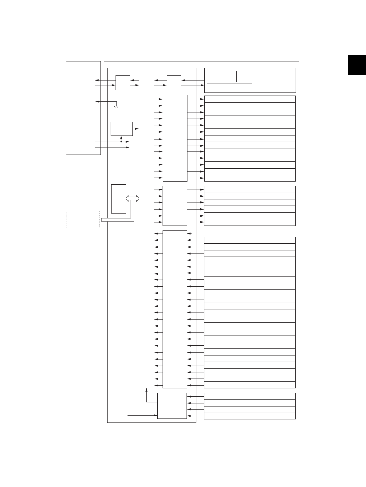
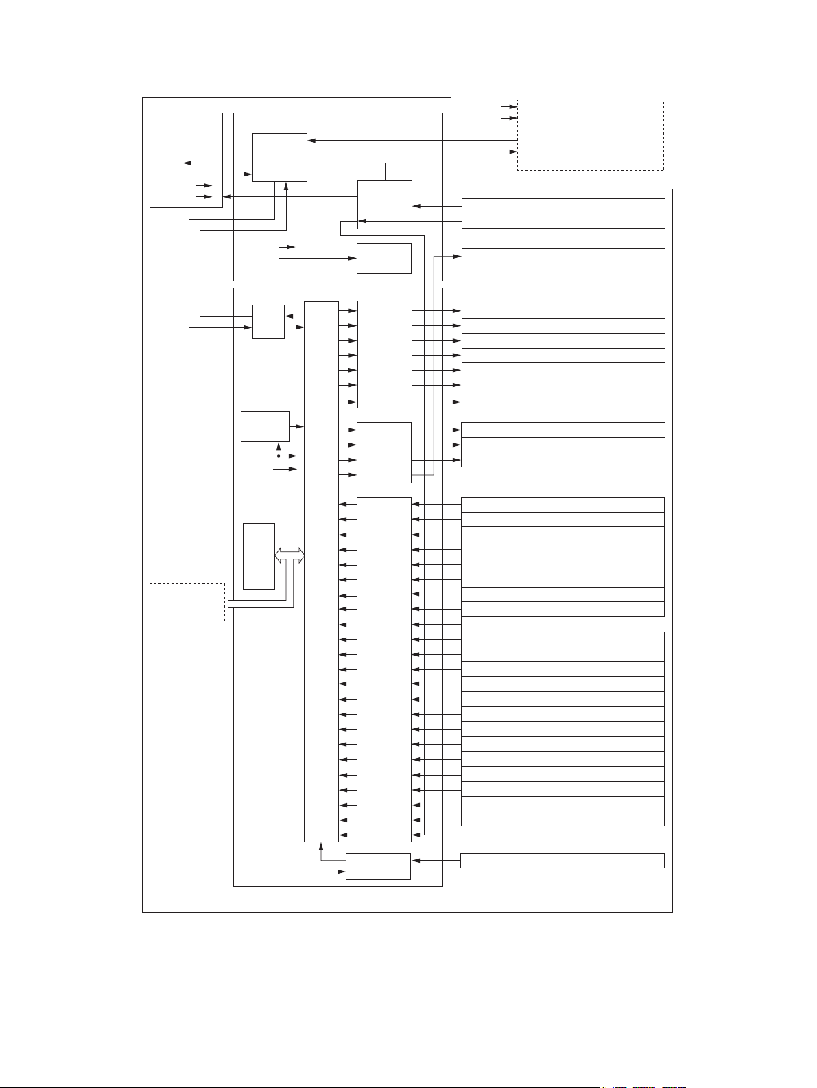
2.5 Diagram of Signal Blocks
GND
DC 24V
DC 5V
FIN board
I/F board
Finisher
TxD
RxD
FINCON
Equipment
Driver
Sensor
input
circuit
I/F
I/F
Reset
circuit
CPU
Stapler unit shift motor (M9)
Paper pusher arm motor (M10)
Shutter clutch (CLT1)
Paper exit guide clutch (CLT2)
Catching solenoid (SOL1)
Buffer roller lift solenoid (SOL2)
Patting solenoid (SOL3)
Gate solenoid (SOL4)
Entrance sensor (S1
)
Buffer tray home position sensor (S3)
Transport sensor (S2
)
Paper pusher home position sensor (S6)
Paddle home position sensor
(S3)
Shutter opening/closing sensor
(S4)
Rear alignment motor (M6)
Transport motor (M7)
Stack transport motor (M8)
Paddle motor (M3)
Buffer roller drive motor (M4)
Front alignment motor (M5)
Entrance motor (M1)
Buffer tray guide motor (M2)
Paper pusher home position sensor (S7
)
Drive
circuit
Exit motor (M11)
Movable tray shift motor (M12)
Stapler motor (M13)
Rear alignment plate home position sensor (S8)
Stack exit belt home position sensor (S9)
Stapler unit home position sensor (S10)
Stapler Interference sensor (S11
)
Finishing tray paper detection sensor (S12
)
Movable tray position-A sensor (S13
)
Movable tray position-B sensor
(
S14
)
Movable tray position-C sensor (S15
)
Movable tray paper-full sensor (S16
)
Movable tray paper exist sensor (S17
)
Stationary tray paper-full sensor (S18
)
Stapler home position sensor (S19)
Staple top position sensor (S20
)
Staple empty sensor (S21
)
Movable tray shift motor sensor (S23)
Connection sensor (S25)
Front cover switch (SW1
)
Stationary tray opening/closing switch (SW2
)
Download jig
ROM
Power
control
circuit
DC 24V
Connection switch (SW4)
Stapler Interference switch (SW3
)
Feeding sensor(S22)
Serial branch
circuit
[A] Finisher section
2
© 2008, 2009 TOSHIBA TEC CORPORATION All rights reserved MJ-1103/1104
Fig. 2-9
2 - 13
GENERAL DESCRIPTION
Page 26
[B] Saddle section
DC 24V
DC 5V
SDL board
I/F board
Finisher
TxD
RxD
TxD
RxD
Driver
I/F
Reset
circuit
CPU
Folding blade clutch (CLT3)
Folding blade clutch (CLT4)
Assisting roller solenoid (SOL6)
Rear saddle stapler motor (M19)
Additional folding motor (M20)
Saddle transport motor (M16)
Folding motor (M17)
Front saddle stapler motor (M18)
Stacker motor (M14)
Transport path switching solenoid (SOL5)
Side alignment motor (M15)
Feeding sensor (S22)
Junction box paper detection sensor (S26)
Drive
circuit
Serial
branch
circuit
Detection
circuit
Signal
switching
circuit
Cover open sensor (S37)
Download jig
ROM
Power control
circuit
DC 24V
Sensor
input
circuit
Transport path-2 sensor (S27)
Exit sensor (S31)
Transport path-3 sensor (S28)
Saddle tray paper detection sensor (S32)
Ejecting roller sensor (S29)
Stacker paper detection sensor (S30)
Stacker home position sensor (S33)
Folding motor encoder sensor (S34)
Folding braid home position sensor (S35)
Side alignment home position sensor (S36)
Paper holding home position sensor (S38)
Additional folding home position sensor (S39)
Exit transport sensor (S41)
Additional folding motor encoder sensor (S42)
Front saddle stapler home position sensor (S43)
Rear saddle stapler home position sensor (S44)
Front saddle staple empty sensor (S45)
Rear saddle staple empty sensor (S46)
Front saddle staple top position sensor (S47)
Rear saddle staple top position sensor (S48)
Front saddle staple cartridge sensor (S49)
Rear saddle staple cartridge sensor (S50)
Option
DC 24V
DC 24V
DC 5V
DC 5V
DC 24V
DC 5V
TxD
RxD
FIN board
MJ-1103/1104 © 2008, 2009 TOSHIBA TEC CORPORATION All rights reserved
GENERAL DESCRIPTION
Fig. 2-10
2 - 14
Page 27
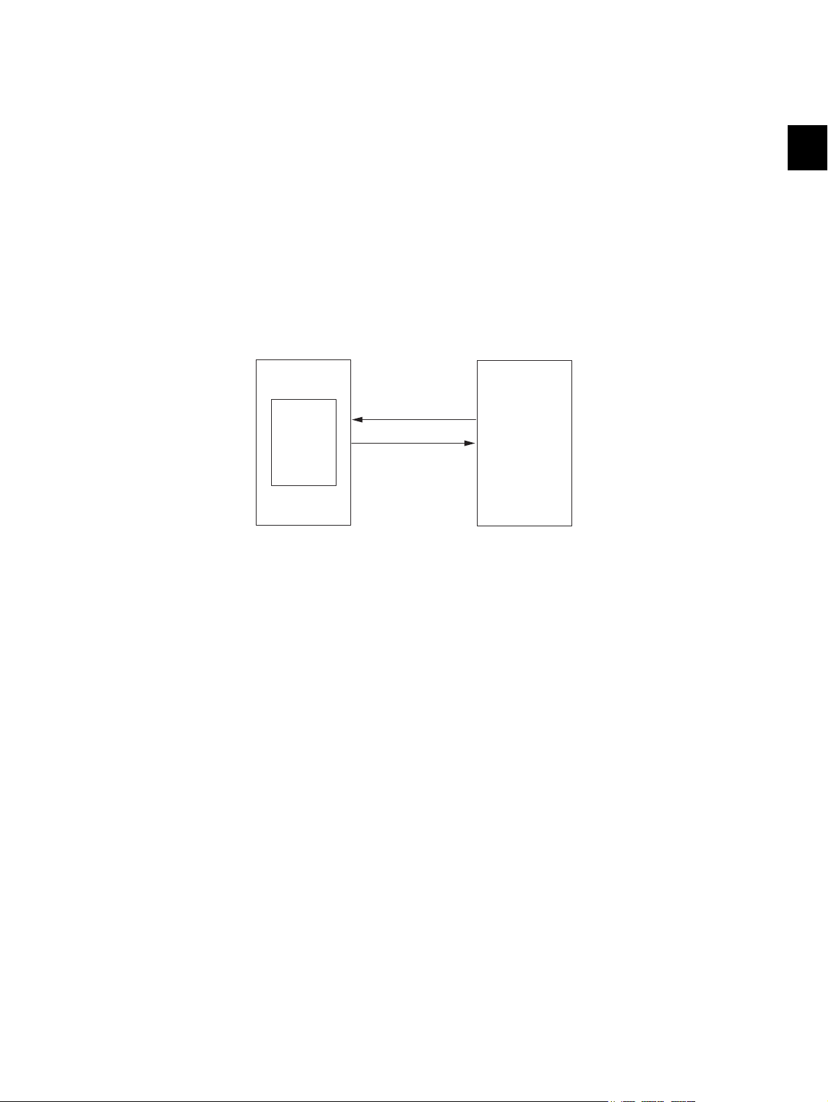
2.6 Description of Interface Signals
TxD
RxD
Finisher
Equipment
Converter
PC board
The 2 lines; TxD and RxD are used to transmit/receive signals between the equipment and the Finisher.
When the Finisher is connected, the equipment detects the power supply signal (MFP-24V-ON) and
confirms that the Finisher is connected to it with the status of the connection switch (SW4) and an MFPCONNECT-SEN signal from the connection sensor (S25).
TXD: Sent data (transmitted from the Equipment to the Finisher)
RXD: Received data (transmitted from the Finisher to the Equipment)
MFP-24-V-ON: Equipment 24V power supply signal (Low level - 24V power supplied)
MFP-CONNECT: Equipment connection switch (Connected - 24V power supplied)
MFP-CONNECT-SEN: Equipment connection confirmation signal
(Low level - Connected to the equipment)
Data communication (RxD and TxD) between the equipment and the Finisher has adopted the serial
communication system which does not allow checking whether the signals are transmitted/ received
properly using testing devices in the field.
2
Fig. 2-11
© 2008, 2009 TOSHIBA TEC CORPORATION All rights reserved MJ-1103/1104
GENERAL DESCRIPTION
2 - 15
Page 28

MJ-1103/1104 © 2008, 2009 TOSHIBA TEC CORPORATION All rights reserved
GENERAL DESCRIPTION
2 - 16
Page 29
3. DESCRIPTION OF OPERATIONS
3.1 Basic Operations
3.1.1 GENERAL DESCRIPTION
This machine receives paper transported from the connected device with its junction box, and then
transports the paper to the stationary tray or the movable tray of the Finisher section or the saddle tray
of the saddle stitch section.
Stack modes available in the Finisher section are; the simple stack mode which directly exits paper to
the stationary tray or the movable tray, the job offset stack mode which exits stacks of paper by slightly
shifting them to the front and rear alternately, and the staple stack mode which staples and exits stacks
of paper.
In the job offset stack mode and the staple stack mode, stacks of paper are exited to the movable tray.
A stack mode available in the saddle stitch section is the center-binding mode which binds a stack of
paper at its center by stapling at two positions and then folds in half again to exit it to the saddle tray.
• Simple stack mode
When the non-sort mode is set, paper exits in the procedure shown below.
A Paper is output to the stationary tray.
B Paper is output to the movable tray via the buffer tray.
Junction boxMovable tray Buffer tray
3
Stationary tray
B
A
Fig. 3-1
• Bundle job offset mode/ stapling stack mode
When the sort copying and the stapling function are set, paper exits in the procedure shown below.
1 Paper is transported to the buffer tray.
2 Paper is dropped from the buffer tray onto the finishing tray.
3 Paper stucked on the finishing tray is aligned and stapled, and then the bundled paper is output
to the movable tray.
Junction boxMovable tray Buffer tray
3
1
2
Finishing tray
Stapler unit
Fig. 3-2
© 2008, 2009 TOSHIBA TEC CORPORATION All rights reserved MJ-1103/1104
3 - 1
DESCRIPTION OF OPERATIONS
Page 30
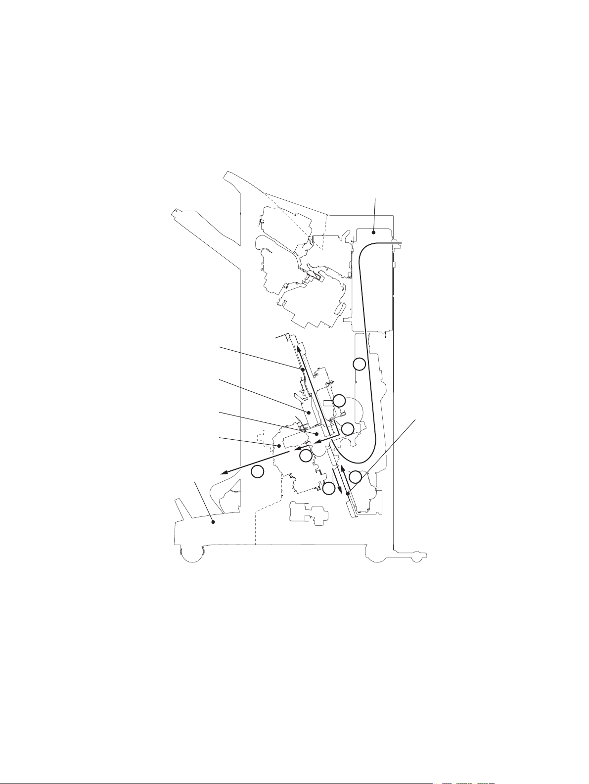
• Center-binding mode
Paper is exited following the procedure below when the Saddle Stitch Finisher is installed.
1 The stacker is moved to the stapling position according to the detected paper size.
2 Paper is transported to the stacker and then side alignment operation is performed.
3 The stack of paper is stapled after the alignment for the last page is finished.
4 The stacker is moved to the paper folding position to fold the paper.
5 The paper is transported to the additional folding position to be folded again.
6 The paper is exited to the saddle tray.
Junction box
Side alignment Unit
Stapler unit
Fold unit
EFS unit
Saddle tray
2
3
Stacker
4
5
6
1
4
Fig. 3-3
MJ-1103/1104 © 2008, 2009 TOSHIBA TEC CORPORATION All rights reserved
DESCRIPTION OF OPERATIONS
3 - 2
Page 31

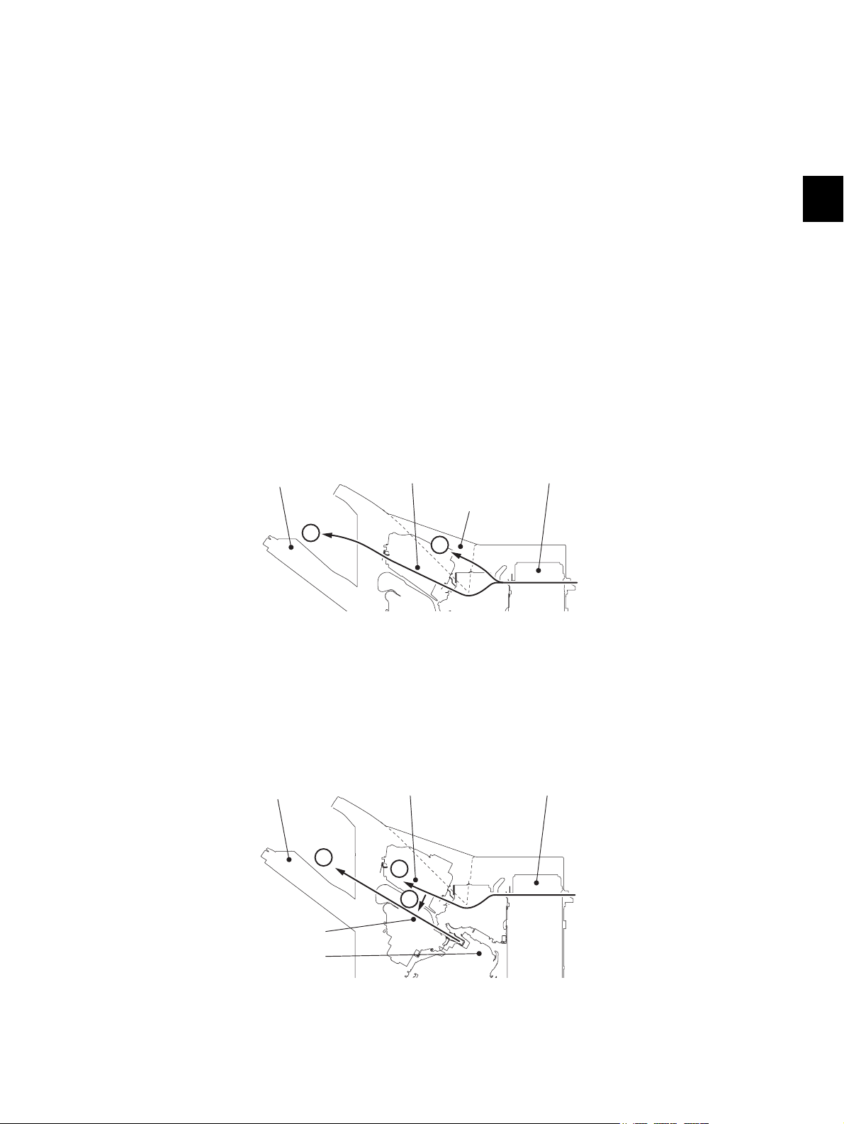
3.1.2 Junction Box
Feeding sensor
Junction box paper detection sensor
Feeding roller
Junction roller
Transport path switching solenoid
Flapper
Entrance roller
Entrance motor
Paper transported from the connected device is then detected by the feeding sensor (S22) and caught
with the feeding roller. Then it is transported to the Finisher section or the saddle stitch section after the
transport path switching solenoid (SOL5) switches its transport path with a flapper.
When it is transported to the Finisher section, the flapper does not move but the entrance roller transports it to the Finisher section.
When it is transported to the saddle stitch section, the transport path switching solenoid (SOL5) is
turned ON to switch the transport path with the flapper. The paper is then transported to the saddle
stitch section with the junction roller. The junction box paper detection sensor (S26) detects the passing
of the paper.
The feeding roller and the junction roller are driven by the entrance motor (M1) of the Finisher section.
3
Fig. 3-4
© 2008, 2009 TOSHIBA TEC CORPORATION All rights reserved MJ-1103/1104
DESCRIPTION OF OPERATIONS
3 - 3
Page 32

3.1.3 Simple Stack Mode
Entrance motor
Gate solenoid
Gate flap
Entrance roller
Entrance sens
In this mode the transported paper is exited to the stationary tray or the movable tray directly, without
any extra operation.
During the exiting process to the movable tray, the shutter is lifted not to bring the paper into the finishing tray side and the movable tray is lifted up and down according to the stack height of paper.
[A] Finisher paper feeding section
Paper transported from the junction box is then caught with the entrance roller driven by the entrance
motor (M1).
When paper is exited to the stationary tray, the gate solenoid (SOL4) is turned ON to move down the
gate flapper. When exited to the movable tray, the gate solenoid (SOL4) is turned OFF to transport the
paper to the buffer tray.
The paper transport is detected by the entrance sensor (S1).
Fig. 3-5
MJ-1103/1104 © 2008, 2009 TOSHIBA TEC CORPORATION All rights reserved
DESCRIPTION OF OPERATIONS
3 - 4
Page 33

[B] Paper exit to the stationary tray
Exit motor
Entrance sensor
Stationary
tray roller
Stationary tray
paper-full sensor
Paper transported from the Finisher feeding section to the stationary tray side is exited to the stationary
tray with the stationary tray roller driven by the exit motor (M11).
The entrance sensor (S1) detects the paper transport to the stationary tray.
The stationary tray paper-full sensor (S18) detects the overload of paper on the stationary tray.
3
Fig. 3-6
© 2008, 2009 TOSHIBA TEC CORPORATION All rights reserved MJ-1103/1104
3 - 5
DESCRIPTION OF OPERATIONS
Page 34

[C] Paper exit to the movable tray
Paper transported from the Finisher feeding section to the movable tray side is transported to the buffer
tray with the exit roller driven by the exit motor (M11).
Paper transport is detected by the transport sensor (S2).
Transport sensor
Buffer tray
Exit roller
Exit motor
Fig. 3-7
The paper transported to the buffer tray it then exited to the movable tray by the buffer rollers driven by
the buffer roller drive motor (M4).
At this stage, the shutter clutch (CLT1) is turned ON and the shutter is pulled up by the drive of the
transport motor (M7) to prevent the paper from being transported to the finishing tray.
The opening and closing statuses of the shutter is detected by the shutter opening/closing sensor (S4).
Shutter
Buffer roller
Buffer roller
drive motor
Buffer tray
Shutter opening/
closing sensor
Buffer tray
Transport motor
Shutter clutch
Fig. 3-8
MJ-1103/1104 © 2008, 2009 TOSHIBA TEC CORPORATION All rights reserved
DESCRIPTION OF OPERATIONS
3 - 6
Page 35

[D] Operation of Movable Tray
The movable tray is shifted up and down by the drive from the movable tray shift motor (M12) according
to the paper exit from the buffer tray or finishing tray, and the amount of the paper stack. Rotation of the
movable tray shift motor is detected by the movable tray shift motor sensor (S23). Whether paper is set
on the movable tray or not is detected by the movable tray paper sensor (S17).
Detecting the position of the movable tray is performed as follows.
1. Home position of the movable tray when the paper is output from the buffer tray
The movable tray is shifted up during initializing until the movable tray paper-full sensor (S16) is
turned ON. After that, the tray is moved down for a specified period of time and it is stopped where
the movable tray position-A sensor (S13) is turned ON. This will be the home position.
2. Home position of the movable tray when the paper is output from the finishing tray
The movable tray is shifted down from the home position when the paper is output from the buffer
tray, and the tray is stopped where the movable tray position-C sensor (S15) is turned ON. This will
be the home position.
3. Position of the movable tray when the paper loading capacity is 1,500 to 3,000 sheets
If the movable tray paper-full sensor (S16) is turned ON when the movable tray is in either the home
position when the paper is output from the buffer tray or the home position when the paper is output
from the finishing tray, it goes down to the position where the movable tray position-B sensor (S14)
is turned ON. This is the position of the movable tray when the paper loading capacity is 1,500 to
3,000 sheets.
4. Position of the movable tray when the paper loading capacity is 3,000 sheets or more
When the movable tray is in the position of the paper loading capacity of 1,500 to 3,000 sheets, and
the movable tray paper-full sensor (S16) is turned ON, the tray is shifted to the position where the
movable tray position-A sensor (S13) is turned OFF. This is the position of the movable tray when
the paper loading capacity is 3,000 or more.
3
Movable tray position Movable tray position
A sensor (S13)
(1) ON OFF OFF
(2) ON OFF ON
(3) ON ON ON
(4) ON ON OFF
Movable tray position
B sensor (S14)
* ON: The sensor signal is interrupted by the rib of the sensor rail.
OFF: The sensor signal is not interrupted by the rib of the sensor rail.
Movable tray position
C sensor (S15)
© 2008, 2009 TOSHIBA TEC CORPORATION All rights reserved MJ-1103/1104
3 - 7
DESCRIPTION OF OPERATIONS
Page 36

Movable tray paper-full sensor
Movable tray
position-A sensor
Movable tray
paper exist sensor
Movable tray
position-C sensor
Movable tray
position-B sensor
Movable tray shift motor
Movable tray
shift motor sensor
Fig. 3-9
MJ-1103/1104 © 2008, 2009 TOSHIBA TEC CORPORATION All rights reserved
DESCRIPTION OF OPERATIONS
3 - 8
Page 37

3.1.4 Job offset stack mode / Staple stack mode
The job offset stack mode exits stacks of paper by slightly shifting them to the front and rear alternately,
and the staple stack mode staples and exits stacks of paper. In both modes, paper transported from the
feeding section is stacked on the buffer tray in the unit of 1 to 3 sheets.
The stacked paper is then moved to the finishing tray by the active drop mechanism. On the finishing
tray the alignment of the stacks of paper and the job offsetting are performed.
In case a stack mode shifts to the staple stack mode after this, the stack of paper is stapled and exited
to the movable tray.
[A] Paper transport section
At this stage, the buffer roller lift solenoid (SOL2) is turned ON to raise the buffer rollers and the buffer
tray is moved by the buffer tray guide motor (M2) to the position where it matches with the paper width.
The home position of the buffer tray is detected by the buffer tray home position sensor (S5).
Buffer tray guide motor
Buffer tray
home position sensor
Buffer roller lift solenoid
3
Buffer roller
Buffer tray
Fig. 3-10
© 2008, 2009 TOSHIBA TEC CORPORATION All rights reserved MJ-1103/1104
3 - 9
DESCRIPTION OF OPERATIONS
Page 38

[B] Mulch-active drop mechanism section
Paper pusher home position sensor
Paper holder cam
Catching
solenoid
Paper pushing arm motor
Paper pushing plate
Paddle guide
Catching pad
The paper transported to the buffer tray is then moved to the finishing tray by the mulch-active drop
mechanism to be aligned or stapled.
(1) The paper on the buffer tray is pulled into the finishing tray side by the reverse rotation of the
buffer roller drive motor (M4).
In this step the paper pushing arm motor (M10) holds the trailing edge of the paper with the paper
pushing plate.
Then the catching solenoid (SOL1) is turned ON to rotate the catching pad, and the catching pad
thus catches the paper with the paddle guides.
MJ-1103/1104 © 2008, 2009 TOSHIBA TEC CORPORATION All rights reserved
DESCRIPTION OF OPERATIONS
Fig. 3-11
3 - 10
Page 39

(2) When the buffer roller lift solenoid (SOL2) is turned ON, the buffer rollers are lifted up, and then
Buffer tray guide motor
Buffer tray
Buffer tray
Buffer roller
lift solenoid
Patting solenoid
Paper tapping arm
Buffer roller
Paddle motor
Transport motor
Stack transport roller-1
Stack transport roller-2
Finishing tray
paper detection sensor
Paddle home position sensor
the buffer tray guide motor (M2) opens the buffer tray.
The paper on the buffer tray is thus dropped onto the finishing tray.
At this stage, the patting solenoid (SOL3) is turned ON to drop the paper tapping arm so that the
paper will certainly be dropped onto the finishing tray.
3
(3) The paper dropped onto the finishing tray is then pulled into the finishing position by the paddles
driven by the paddle motor (M8) and the stack transport rollers-1 and -2 driven by the transport
motor (M7).
The finishing tray paper detection sensor (S12) detects whether paper is on the finishing tray or
not.
The home position of the paddles is detected by the paddle home position sensor (S3).
Fig. 3-12
© 2008, 2009 TOSHIBA TEC CORPORATION All rights reserved MJ-1103/1104
Fig. 3-13
3 - 11
DESCRIPTION OF OPERATIONS
Page 40

[C] Bundle Job Offset Operation
Stapler unit shift motor
Stapler unit
home position sensor
Stapler interference switch
Stapler interference
sensor
The bundle job offset operation is to sort bundles of paper by placing the first bundle a little forward and
placing the next bundle a little backward, and repeating this set of movement.
The paper transported to the finishing tray is bundled and each bundle is placed by the alignment plates
driven by the front alignment motor (M5) and the rear alignment motor (M6).
The home position of each alignment plate is detected by the front alignment plate home position sensor (S7) and the rear alignment plate home position sensor (S8).
Alignment plateAlignment plate
Front alignment plate
home position sensor
Front alignment motor
Rear alignment plate
home position sensor
Rear alignment motor
Fig. 3-14
[D] Stapling Operation
The stapling operation is to staple a specified number of paper with the stapler unit.
The stapler unit is moved to the stapling position (the position differs depending on the paper size) by
the stapler unit shift motor (M9).
The home position of the stapler unit is detected by the stapler unit home position sensor (S10).
The stapler interference switch (SW3) detects the no-operation area for the stapling operation and cuts
off the power supply to the stapler while it is switched ON.
The stapling operation is also stopped in the area where while the stapler interference sensor (S11) is
turned ON to prevent the stapler from interfering with other mechanical sections in the equipment.
MJ-1103/1104 © 2008, 2009 TOSHIBA TEC CORPORATION All rights reserved
DESCRIPTION OF OPERATIONS
Fig. 3-15
3 - 12
Page 41

[E] Paper exiting operation
Bundles of the paper aligned or stapled on the finishing tray are then pulled up by the paper exit guide
driven by the stack transport motor (M8) with the turning ON of the paper exit guide clutch (CLT2).
Then the paper is exited by the paper exit belt driven by the stack transport motor (M8) and the stack
transport rollers-1 and -2 driven by the transport motor (M2) onto the movable tray.
The home position of the paper exit belt is detected by the stack exit belt home position sensor (S9).
Stack transport roller-2
3
Paper exit belt
Stack transport motor
Paper exit guide
clutch
Stack exit belt
home position sen
Transport motor
Stack transport roller-1
Paper exit guide
Fig. 3-16
© 2008, 2009 TOSHIBA TEC CORPORATION All rights reserved MJ-1103/1104
3 - 13
DESCRIPTION OF OPERATIONS
Page 42

3.1.5 Operation in the saddle stitch section
Saddle transport
motor
Junction box
paper detection
sensor
Junction box
Transport path-2
sensor
Transport path-3
sensor
Assisting roller
solenoid
Transport roller
Ejecting roller sensor
Ejecting roller
Assisting roller
Saddle transport
motor
Junction box
paper detection
sensor
Transport path-2
sensor
Transport path-3
sensor
Assisting roller
solenoid
Transport roller
Ejecting roller
sensor
Ejecting roller
Assisting roller
The center-binding mode binds a stack of paper at its center by stapling at two positions and then folds
in half again to exit it to the saddle tray. In this mode paper transported from the feeding section is
stacked on the stacker. The stacks of paper are aligned on the stacker and moved to the stapling position together with the stacker. Then the moved stacks are fixed and stapled, and then moved to the folding position. Then they are folded with the folding blade and the folding roller. After this, the folded
stacks are again folded and exited to the saddle tray.
[A] Saddle stitch feeding section
Paper transported from the junction box is then transported to the stacker with the transport roller, ejecting roller and assisting roller driven by the saddle transport motor (M16).
The junction box paper detection sensor (S26), transport path-2 sensor (S27), transport path-3 sensor
(S28) and ejecting roller sensor (S29) detect the passing of the paper.
When the ejecting roller sensor (S29) detects that paper has passed, the assisting roller solenoid
(SOL6) is turned ON to contact the assisting roller with the paper to transport it to the stacker.
MJ-1103/1104 © 2008, 2009 TOSHIBA TEC CORPORATION All rights reserved
DESCRIPTION OF OPERATIONS
Fig. 3-17
3 - 14
Page 43

[B] Stack transport
Stacker carrier
Stacker home position sensor
Stacker motor
Stacker paper detection sensor
Side alignment motor
Jog
Side alignment
home position
sensor
Jog
A stacker carrier is moved to the stapling position or the folding position by the stacker motor (M14).
The home position of the stacker is detected by the stacker home position sensor (S33).
The presence of paper in the stacker is detected by the stacker paper detection sensor (S30).
3
Fig. 3-18
[C] Side alignment
Stacks of paper transported to the stacker are aligned to fix their sideways deviation with a jog moved
by the side alignment motor (M15).
The home position of the jog is detected by the side alignment home position sensor (S36).
© 2008, 2009 TOSHIBA TEC CORPORATION All rights reserved MJ-1103/1104
Fig. 3-19
DESCRIPTION OF OPERATIONS
3 - 15
Page 44

[D] Paper holding
Paper holding home position sensor
Paper holding clutch
saddle transport motor
Paper holding damper
Paper holding cam
The paper holding clutch (CLT4) is turned ON to let the saddle transport motor (M16) drive the paper
holding cam.
The home position of the paper holding cam is detected by the paper holding home position sensor
(S38).
[E] Stapling
Stacks of paper aligned and fixed at the stapling position are stapled with two stapler units on the front
and rear sides.
Fig. 3-20
MJ-1103/1104 © 2008, 2009 TOSHIBA TEC CORPORATION All rights reserved
DESCRIPTION OF OPERATIONS
3 - 16
Page 45

[F] Folding
The folding blade is pressed onto the center of the stack of paper stapled and moved to the folding
position, and then the folding roller lets the stack of paper sandwich the blade so that the stack will be
folded again.
The folding blade clutch (CLT3) is turned ON to press the folding blade to the stack of paper by rotating
the blade cam driven by the folding motor (M17).
The rotation of the folding motor (M17) is detected by the folding motor encoder sensor (S34).
Folding motor encoder sensor
Folding motor
Folding blade clutch
Folding blade cam
Folding blade
Folding blade cam
3
Fig. 3-21
Folding blade
home position
sensor
© 2008, 2009 TOSHIBA TEC CORPORATION All rights reserved MJ-1103/1104
3 - 17
DESCRIPTION OF OPERATIONS
Page 46

After this, the stack of paper is folded as it passes the folding roller driven by the folding motor (M17).
Folding motor encoder sensor
Folding motor
Folding blade clutch
Exit transport sensor
Folding roller
Fig. 3-22
MJ-1103/1104 © 2008, 2009 TOSHIBA TEC CORPORATION All rights reserved
DESCRIPTION OF OPERATIONS
3 - 18
Page 47

[G] Additional folding / exiting
Additional folding
home position sensor
Additional folding carrier
Additional
folding carrier
roller
Additional
folding motor
Additional folding
motor encoder sensor
Exit transport sensor
Folding motor
Saddle tray
Saddle exit roller
Exit sensor
Folding roller
Stack tray paper
detection sensor
The stack of paper folded by the folding roller is stopped with the exit transport sensor (S41) at the stopping position. The folded paper is then folded again by moving the additional folding carrier roller forward and backward.
The home position of the additional folding carrier is detected by the additional folding home position
sensor (S39).
The additional folding carrier is driven by the additional folding motor (M20). The rotation of the additional folding motor (M20) is detected by the additional folding motor encoder sensor (S42).
3
After this, the paper is exited to the saddle tray with the saddle exit roller driven by the folding motor
(M17).
The passing of the paper is detected by the exit sensor (S31).
The presence of paper on the saddle tray is detected by the stack tray paper detection sensor (S32).
Fig. 3-23
© 2008, 2009 TOSHIBA TEC CORPORATION All rights reserved MJ-1103/1104
Fig. 3-24
DESCRIPTION OF OPERATIONS
3 - 19
Page 48

3.2 Flow Chart
[A] Simple stack mode
START
Entrance motor ON
Exit motor ON
Entrance sensor ON?
YES
Gate solenoid ON?
YES (Paper exit to the stationary tray)
End
NO
NO
(Paper exit to the
movable tray)
Paper jam
Transport sensor ON?
YES
NO
Shutter clutch ON
Transport motor ON
Shutter opening/closing sensor ON
Movable tray shift motor ON
Movable tray paper-full sensor ON
Movable tray shift motor ON (Reverse)
Movable tray position sensor ON
Movable tray upper position sensor ON
Movable tray lower position sensor ON
Buffer roller drive motor ON
Paper jam
End
Fig. 3-25
MJ-1103/1104 © 2008, 2009 TOSHIBA TEC CORPORATION All rights reserved
DESCRIPTION OF OPERATIONS
3 - 20
Page 49

[B] Bundle job offset mode/ stapling stack mode
START
Paper jam
Entrance sensor ON?
Entrance motor ON
Exit motor ON
Stapler unit shift motor ON
Stapler unit home position sensor ON
Stapler Interference switch ON
Stapler Interference sensor ON
Patting solenoid ON
Buffer tray guide motor ON
Buffer tray home position sensor ON
Paddle motor ON
Paddle home position sensor ON
NO
Finishing tray paper
detection sensor ON?
Paper jam
YES
NO
Paper holding arm motor ON
Catching solenoid ON
Buffer roller lift solenoid ON
Buffer roller drive motor ON (Reverse)
Buffer tray guide motor ON
Buffer tray home position sensor ON
Paper exit guide clutch ON
Paper exit guide clutch ON
Stack transport motor ON
Stack exit belt home position sensor ON
End
Shutter clutch ON
Transport motor ON
Shutter opening/closing sensor ON
Movable tray shift motor ON
Movable tray paper-full sensor ON
Movable tray shift motor ON (Reverse)
Movable tray position sensor ON
Movable tray upper position sensor ON
Movable tray lower position sensor ON
YES
Buffer roller lift solenoid ON
Paper jam
NO
YES
Transport sensor ON?
Staple stack mode
Front alignment motor ON
Front alignment plate home position sensor ON
Rear alignment motor ON
Rear alignment plate home position sensor ON
3
© 2008, 2009 TOSHIBA TEC CORPORATION All rights reserved MJ-1103/1104
Fig. 3-26
3 - 21
DESCRIPTION OF OPERATIONS
Page 50

[C] Center-binding mode
START
Entrance motor ON
Feeding sensor ON?
YES
Transport path-2 sensor ON?
YES
Saddle transport motor ON
Ejecting roller sensor ON?
YES
Assisting roller solenoid ON
NO
NO
NO
Rear saddle stapler motor ON
Rear saddle stapler home position sensor ON
Rear saddle staple empty sensor ON
Rear saddle staple cartridge sensor ON
Paper jam
Front saddle stapler motor ON
Front saddle stapler home position sensor ON
Front saddle staple empty sensor ON
Front saddle staple cartridge sensor ON
Paper jam
Stacker motor ON
Paper holding clutch ON
Saddle transport motor ON
Paper jam
Folding blade clutch ON
Folding motor ON
Stacker paper detection sensor ON?
YES
NO
Side alignment motor ON
Paper holding clutch ON
Saddle transport motor ON
Paper jam
Exit transport sensor ON?
Additional folding motor ON
Folding motor ON
Exit sensor OFF
Fig. 3-27
End
YES
YES
NO
NO
Paper jam
Paper jam
MJ-1103/1104 © 2008, 2009 TOSHIBA TEC CORPORATION All rights reserved
DESCRIPTION OF OPERATIONS
3 - 22
Page 51

3.3 Description Of Circuit
3.3.1 Finishier section
[A] Buffer roller drive circuit
The buffer roller drive circuit controls the rotation and stoppage, rotational direction and motor current of
the buffer roller drive motor.
The buffer roller drive motor is driven by pulse signals (MT4-OUT1A, MT4-OUT1B, MT4-OUT2A and
MT4-OUT2B) output from the motor driver (IC47) under the command of a clock signal (TIOCA4), a
rotational direction signal (MOT4-DIR) and a current setting signals (MOT4-CUR1 and MOT4-CUR0)
from the CPU of the finisher control PC board, and thus this motor rotates the buffer roller.
3
TIOCA4
MOT4-
DIR
MOT4-
CUR1
MOT4-
CUR0
Motor rotation Remarks
Clock signal H L H Normal (Low power) Paper is transported to the movable tray.
Clock signal H L L Normal (Normal power)
Clock signal L L H Reverse (Low power) Not used.
Clock signal L L L Reverse (Normal
power)
--H- Stop
Finisher control PC board
VM
3.3V
CN11
MT4-OUT1A
MT4-OUT2A
MT4-OUT1B
MT4-OUT2B
Buffer roller
drive motor
(M4)
IC21
CPU
MOT4-DIR
MOT4-CUR0
MOT4-CUR1
P-RESET
P-RESET
TIOCA4
Current
control
circuit
13
16
20
17
5
IC47
Motor driver
SG
Fig. 3-28
24
1
21
4
© 2008, 2009 TOSHIBA TEC CORPORATION All rights reserved MJ-1103/1104
DESCRIPTION OF OPERATIONS
3 - 23
Page 52

[B] Paper pushing arm motor drive circuit
IC21
CPU
TIOCC0
MOT10-DIR
MT10-OUT1A
VM
MT10-OUT2A
MT10-OUT1B
MT10-OUT2B
SG
MOT10-CUR0
24
4
1
21
5
MOT10-CUR1
16
20
13
P-RESET
P-RESET
3.3V
Paper pushing
arm motor
(M10)
IC49
Motor driver
Finisher control PC board
CN19
17
Current
control
circuit
The paper pushing arm motor drive circuit controls the rotation and stoppage, rotational direction and
motor current of the paper pushing arm motor.
The paper pushing arm motor is driven by pulse signals (MT10-OUT1A, MT10-OUT1B, MT10-OUT2A
and MT10-OUT2B) output from the motor driver (IC49) under the command of a clock signal (TIOCC0),
a rotational direction signal (MOT10-DIR) and a current setting signals (MOT10-CUR1 and MOT10CUR0) from the CPU of the finisher control PC board, and thus this motor holds the paper with the
paper pushing plate.
TIOCC0
MOT10
-DIR
MOT10
-CUR1
MOT10
-CUR0
Motor rotation Remarks
Clock signal H L H Normal (Low power) The trailing edge of the paper is held down
Clock signal H L L Normal (Normal power)
by the paper pushing plate.
Clock signal L L H Reverse (Low power) Not used
Clock signal L L L Reverse (Normal
power)
--H- Stop
Fig. 3-29
MJ-1103/1104 © 2008, 2009 TOSHIBA TEC CORPORATION All rights reserved
DESCRIPTION OF OPERATIONS
3 - 24
Page 53

[C] Buffer tray guide motor drive circuit
IC21
CPU
TIOCA5
MOT2-DIR
MOT2-OUT1A
VM
MOT2-OUT2A
MOT2-OUT1B
MOT2-OUT2B
SG
MOT2-CUR0
24
4
1
21
5
MOT2-CUR1
16
20
13
P-RESET
P-RESET
3.3V
Buffer tray
guide motor
(M2)
IC48
Motor driver
Finisher control PC board
CN11
17
Current
control
circuit
The buffer tray guide motor drive circuit controls the rotation and stoppage, rotational direction and
motor current of the buffer tray guide motor.
The buffer tray guide motor is driven by pulse signals (MOT2-OUT1A, MOT2-OUT1B, MOT2-OUT2A
and MOT2-OUT2B) output from the motor driver (IC48) under the command of a clock signal (TIOCA5),
a rotational direction signal (MOT2-DIR) and a current setting signals (MOT2-CUR1 and MOT2-CUR0)
from the CPU of the finisher control PC board, and thus this motor opens or closes the buffer tray guide.
TIOCA5
MOT2-
DIR
Clock signal H L H Normal (Low power) The guide is closed.
Clock signal H L L Normal (Normal power)
Clock signal L L H Reverse (Low power) The guide is opened.
Clock signal L L L Reverse (Normal
--H- Stop
MOT2-
CUR1
MOT2-
CUR0
Motor rotation Remarks
power)
3
© 2008, 2009 TOSHIBA TEC CORPORATION All rights reserved MJ-1103/1104
Fig. 3-30
DESCRIPTION OF OPERATIONS
3 - 25
Page 54

[D] Front / rear alignment motor drive circuit
The front / rear alignment motor drive circuit controls the rotation and stoppage, rotational direction and
motor current of the front alignment motor.
The front alignment motor is driven by pulse signals (MT5-OUT1A, MT5-OUT1B, MT5-OUT2A and
MT5-OUT2B) output from the motor driver (IC45) under the command of a clock signal (TMO2), a rotational direction signal (MOT5-DIR) and a current setting signals (MOT5-CUR1 and MOT5-CUR0) from
the CPU of the finisher control PC board, and thus this motor opens or closes the front alignment plate
of the finishing tray.
The rear alignment motor is driven by pulse signals (MT6-OUT1A, MT6-OUT1B, MT6-OUT2A and
MT6-OUT2B) output from the motor driver (IC41) under the command of a clock signal (TMO3), a rotational direction signal (MOT6-DIR) and a current setting signals (MOT6-CUR1 and MOT6-CUR0) from
the CPU of the finisher control PC board, and thus this motor opens or closes the rear alignment plate
of the finishing tray.
TMO2
MOT5-
DIR
MOT5-
CUR1
MOT5-
CUR0
Motor rotation Remarks
Clock signal H L H Normal (Low power) The front alignment plate is closed.
Clock signal H L L Normal (Normal power)
Clock signal L L H Reverse (Low power) The front alignment plate is opened.
Clock signal L L L Reverse (Normal
power)
--H- Stop
TMO3
MOT6-
DIR
MOT6-
CUR1
MOT6-
CUR0
Motor rotation Remarks
Clock signal H L H Normal (Low power) The rear alignment plate is closed.
Clock signal H L L Normal (Normal power)
Clock signal L L H Reverse (Low power) The rear alignment plate is opened.
Clock signal L L L Reverse (Normal
power)
--H- Stop
Finisher control PC board
VM
3.3V
MOT5/6-OUT1A
MOT5/6-OUT2A
CN17
MOT5/6-OUT1B
MOT5/6-OUT2B
Front / rear
alignment motor
(M5 / M6)
IC21
CPU
P-RESET
P-RESET
TMO2 / 3
MOT5/6-DIR
MOT5/6-CUR0
MOT5/6-CUR1
Current
control
circuit
13
16
20
17
5
IC45 / IC41
Motor driver
24
1
21
4
SG
Fig. 3-31
MJ-1103/1104 © 2008, 2009 TOSHIBA TEC CORPORATION All rights reserved
DESCRIPTION OF OPERATIONS
3 - 26
Page 55

[E] Stack transport motor drive circuit
IC21
CPU
TIOCA3
MOT8-OUT1A
VM
MOT8-OUT2A
MOT8-OUT1B
MOT8-OUT2B
SG
MOT8-DIR
24
4
1
21
5
20
16
13
P-RESET
P-RESET
3.3V
Stack
transport motor
(M8)
IC38
Motor driver
Finisher control PC board
MOT8-CUR1
17
MOT8-CUR0
Current
control
circuit
CN17
The stack transport motor drive circuit controls the rotation and stoppage, rotational direction and motor
current of the stack transport motor.
The stack transport motor is driven by pulse signals (MOT8-OUT1A, MOT8-OUT1B, MOT8-OUT2A
and MT8-OUT2B) output from the motor driver (IC38) under the command of a clock signal (TIOCA3),
a rotational direction signal (MOT8-DIR) and current setting signals (MOT8-CUR1 and MOT8-CUR0)
from the CPU of the finisher control PC board, and thus this motor rotates the stack transport belt.
TIOCA3
MOT8-
DIR
Clock signal H L H Normal (Low power) Not used.
Clock signal H L L Normal (Normal power)
Clock signal L L H Reverse (Low power) Paper is transported to the movable tray.
Clock signal L L L Reverse (Normal
--H- Stop
MOT8-
CUR1
MOT8-
CUR0
Motor rotation Remarks
power)
3
© 2008, 2009 TOSHIBA TEC CORPORATION All rights reserved MJ-1103/1104
Fig. 3-32
DESCRIPTION OF OPERATIONS
3 - 27
Page 56

[F] Entrance motor drive circuit
IC21
CPU
TIOCA1
MOT1-CUR1
MOT1-A
VM
MOT1-C
MOT1-B
MOT1-D
SG
MOT1-DIR
1
21
3
23
15
16
10
13
P-RESET
P-RESET
3.3V
IC1
Motor driver
2
4
22
20
MOT1-CUR0
CN26
Entrance motor
(M1)
Finisher control PC board
Current
control
circuit
The entrance motor drive circuit controls the rotation and stoppage, rotational direction and motor current of the entrance motor.
The entrance motor is driven by pulse signals (MOT1-OUT1A, MOT1-OUT1B, MOT1-OUT2A and
MOT1-OUT2B) output from the motor driver (IC1) under the command of a clock signal (TIOCA1), a
rotational direction signal (MOT1-DIR) and current setting signals (MOT1-CUR1 and MOT1-CUR0)
from the CPU of the finisher control PC board, and thus this motor rotates the feeding roller, junction
roller and entrance roller.
TIOCA1
MOT8-
DIR
MOT8-
CUR1
MOT8-
CUR0
Motor rotation Remarks
Clock signal H L H Normal (Low power) Paper is pulled in.
Clock signal H L L Normal (Normal power)
Clock signal L L H Reverse (Low power) Not Used.
Clock signal L L L Reverse (Normal
power)
--H- Stop
Fig. 3-33
MJ-1103/1104 © 2008, 2009 TOSHIBA TEC CORPORATION All rights reserved
DESCRIPTION OF OPERATIONS
3 - 28
Page 57

[G] Exit motor drive circuit
IC21
CPU
TIOCA2
MOT11-CUR1
MT11-A
VM
MT11-C
MT11-B
MT11-D
SG
MOT11-DIR
1
21
3
23
15
16
10
13
P-RESET
P-RESET
3.3V
IC44
Motor driver
2
4
22
20
MOT11-CUR0
CN19
Exit motor
(M11)
Finisher control PC board
Current
control
circuit
The exit motor drive circuit controls the rotation and stoppage, rotational direction and motor current of
the exit motor.
The exit motor is driven by pulse signals (MT11-OUT1A, MT11-OUT1B, MT11-OUT2A and MT11OUT2B) output from the motor driver (IC44) under the command of a clock signal (TIOCA2), a rotational direction signal (MOT11-DIR) and current setting signals (MOT11-CUR1 and MOT11-CUR0) from
the CPU of the finisher control PC board, and thus this motor rotates the stationary tray roller and exit
roller.
3
TIOCA2
MOT11
-DIR
MOT11
-CUR1
MOT11
-CUR0
Motor rotation Remarks
Clock signal H L H Normal (Low power) Not used.
Clock signal H L L Normal (Normal power)
Clock signal L L H Reverse (Low power) Paper is transported to the stationary tray
Clock signal L L L Reverse (Normal
or buffer tray.
power)
--H- Stop
Fig. 3-34
© 2008, 2009 TOSHIBA TEC CORPORATION All rights reserved MJ-1103/1104
3 - 29
DESCRIPTION OF OPERATIONS
Page 58

[H] Stapler unit shift motor drive circuit
IC21
CPU
TIOCA3
MOT9-CUR1
MOT9-A
VM
MOT9-C
MOT9-B
MOT9-D
SG
MOT9-DIR
1
21
3
23
15
16
10
13
P-RESET
P-RESET
3.3V
IC42
Motor driver
2
4
22
20
MOT9-CUR0
CN10
Stapler unit
shift motor
(M9)
Finisher control PC board
Current
control
circuit
The stapler unit shift motor drive circuit controls the rotation and stoppage, rotational direction and
motor current of the stapler unit shift motor.
The stapler unit shift motor is driven by pulse signals (MOT9-OUT1A, MOT9-OUT1B, MOT9-OUT2A
and MOT9-OUT2B) output from the motor driver (IC42) under the command of a clock signal (TIOCA3),
a rotational direction signal (MOT9-DIR) and a current setting signals (MOT9-CUR1 and MOT9-CUR0)
from the CPU of the finisher control PC board, and thus this motor shifts the stapler unit back and forth.
TIOCA3
MOT9-
DIR
MOT9-
CUR1
MOT9-
CUR0
Motor rotation Remarks
Clock signal H L H Normal (Low power) The stapler unit is shifted to the front side.
Clock signal H L L Normal (Normal power)
Clock signal L L H Reverse (Low power) The stapler unit is shifted to the rear side.
Clock signal L L L Reverse (Normal
power)
--H- Stop
Fig. 3-35
MJ-1103/1104 © 2008, 2009 TOSHIBA TEC CORPORATION All rights reserved
DESCRIPTION OF OPERATIONS
3 - 30
Page 59

[I] Transport motor drive circuit
IC21
CPU
TIOCA0
MOT7-OUT1A
VM
MOT7-OUT2A
MOT7-OUT1B
MOT7-OUT2B
SG
MOT7-DIR
24
4
1
21
5
20
16
13
P-RESET
P-RESET
3.3V
Transport motor
(M7)
IC43
Motor driver
Finisher control PC board
MOT7-CUR1
17
MOT7-CUR0
Current
control
circuit
CN10
The transport motor drive circuit controls the rotation and stoppage, rotational direction and motor current of the transport motor.
The transport motor is driven by pulse signals (MOT7-OUT1A, MOT7-OUT1B, MOT7-OUT2A and
MOT7-OUT2B) output from the motor driver (IC43) under the command of a clock signal (TIOCA0), a
rotational direction signal (MOT7-DIR) and current setting signals (MOT7-CUR1 and MOT7-CUR0)
from the CPU of the finisher control PC board, and thus this motor rotates the stack transport roller-1
and -2.
3
TIOCA0
MOT7-
DIR
MOT7-
CUR1
MOT7-
CUR0
Motor rotation Remarks
Clock signal H L H Normal (Low power) Paper is transported to the finishing posiClock signal H L L Normal (Normal power)
tion.
Clock signal L L H Reverse (Low power) Paper is transported to the movable tray.
Clock signal L L L Reverse (Normal
power)
--H- Stop
Fig. 3-36
© 2008, 2009 TOSHIBA TEC CORPORATION All rights reserved MJ-1103/1104
DESCRIPTION OF OPERATIONS
3 - 31
Page 60

[J] Paddle motor drive circuit
IC21
CPU
TIOCC3
MOT3-OUT1A
VM
MOT3-OUT2A
MOT3-OUT1B
MOT3-OUT2B
SG
MOT3-DIR
24
4
1
21
5
20
16
13
P-RESET
P-RESET
3.3V
Paddle motor
(M3)
IC2
Motor driver
Finisher control PC board
MOT3-CUR1
17
MOT3-CUR0
Current
control
circuit
CN22
The paddle motor drive circuit controls the rotation and stoppage, rotational direction and motor current
of the paddle motor.
The paddle motor is driven by pulse signals (MOT3-OUT1A, MOT3-OUT1B, MOT3-OUT2A and MOT3OUT2B) output from the motor driver (IC2) under the command of a clock signal (TIOCC3), a rotational
direction signal (MOT3-DIR) and a current setting signals (MOT3-CUR1 and MOT3-CUR0) from the
CPU of the finisher control PC board, and thus this motor rotates the paddle.
TIOCC3
MOT3-
DIR
MOT3-
CUR1
MOT3-
CUR0
Motor rotation Remarks
Clock signal H L H Normal (Low power) Paper is pulled into the finishing position
Clock signal H L L Normal (Normal power)
and then pushed off.
Clock signal L L H Reverse (Low power) Eliminates backlash.
Clock signal L L L Reverse (Normal
power)
--H- Stop
Fig. 3-37
MJ-1103/1104 © 2008, 2009 TOSHIBA TEC CORPORATION All rights reserved
DESCRIPTION OF OPERATIONS
3 - 32
Page 61

[K] Movable tray shift motor drive circuit
IC21
CPU
DM1-CNT0
DM1-F
VM5VPA
Movable tray
shift motor
(M12)
Motor drive circuit
Finisher control PC board
Overcurrent
protection circuit
DM1-R
DM1-CNT1
CN16
The movable tray shift motor drive circuit controls the rotation and stoppage, rotational direction and
motor current of the movable tray shift motor.
The movable tray shift motor is a DC motor which is driven by rotation control signals (DM1-CNT1 and
DM1-CNT0) from the CPU of the finisher control PC board, and thus this motor shifts the movable tray
in a hoisting movement. For the case when an overcurrent status is detected, a protection circuit is
mounted to turn the movable tray shift motor off.
DM1-CNT0 DM1-CNT1 Motor rotation Remarks
H L Normal The movable tray unit is shifted to the lower side.
L H Reverse The movable tray unit is shifted to the upper side.
HH Stop
LL Stop
3
Fig. 3-38
© 2008, 2009 TOSHIBA TEC CORPORATION All rights reserved MJ-1103/1104
3 - 33
DESCRIPTION OF OPERATIONS
Page 62

[L] Stapler motor drive circuit
IC21
CPU
DM3-CNT0
DM3-F
VM5VPA
Stapler motor
(M13)
Motor drive circuit
Finisher control PC board
Overcurrent
protection circuit
DM3-R
DM3-CNT1
CN19
5VPA
IC22
RESET
1
2
5
SG
The stapler motor drive circuit controls the rotation and stoppage, rotational direction and motor current
of the stapler motor.
The stapler motor is a DC motor which is driven by rotation control signals (DM3-CNT1 and DM3CNT0) from the CPU of the finisher control PC board, and thus this motor performs a stapling operation. For the case when an overcurrent status is detected, a protection circuit is mounted to turn the stapler motor off.
DM3-CNT0 DM3-CNT1 Motor rotation Remarks
H L Normal Operates the stapler.
L H Reverse Recovery operation
HH Stop
LL Stop
[M] Reset circuit
The reset circuit generates a reset signal when the power is turned ON and when the power supply
voltage is lowered. When 5VPA voltage is 4.25V or lower, the reset IC (IC22) resets the CPU (IC21)
and Flash ROM (IC4) by determining that the output of pin 1 is at a low level.
MJ-1103/1104 © 2008, 2009 TOSHIBA TEC CORPORATION All rights reserved
DESCRIPTION OF OPERATIONS
Fig. 3-39
Fig. 3-40
3 - 34
Page 63

3.3.2 Saddle section
IC31
CPU
TMO2
MOT3-CUR0
MOT3-OUT1A
VM
MOT3-OUT2A
MOT3-OUT1B
MOT3-OUT2B
SG
MOT3-DIR
24
4
1
21
5
20
16
17
13
P-RESET
P-RESET
3.3V
Stacker motor
(M14)
IC17
Motor driver
Saddle control PC board
CN4
[A] Stacker motor drive circuit
The stacker motor drive circuit controls the rotation and stoppage, rotational direction and motor current
of the stacker motor.
The stacker motor is driven by pulse signals (MOT3-OUT1A, MOT3-OUT1B, MOT3-OUT2A and
MOT3-OUT2B) output from the motor driver (IC17) under the command of a clock signal (TMO2), a
rotational direction signal (MOT3-DIR) and a current setting signal (MOT9-CUR0) from the CPU of the
saddle control PC board, and thus this motor shifts the stacker stapling position and folding position.
TMO2 MOT3-DIR MOT3-CUR0 Motor rotation Remarks
Clock signal H L Normal The stacker is moved to the stapling
position.
3
Clock signal L L Reverse The stacker is moved to the folding
position.
--HStop
Fig. 3-41
© 2008, 2009 TOSHIBA TEC CORPORATION All rights reserved MJ-1103/1104
DESCRIPTION OF OPERATIONS
3 - 35
Page 64

[B] Side alignment motor drive circuit
The side alignment motor drive circuit controls the rotation and stoppage, rotational direction and motor
current of the side alignment motor.
The side alignment motor is driven by pulse signals (MOT4-OUT1A, MOT4-OUT1B, MOT4-OUT2A and
MOT4-OUT2B) output from the motor driver (IC11) under the command of a clock signal (TMO3), a
rotational direction signal (MOT4-DIR) and a current setting signal (MOT4-CUR0) from the CPU of the
saddle control PC board, and thus this motor opens or closes the jog.
TMO3 MOT4-DIR MOT4-CUR0 Motor rotation Remarks
Clock signal H L Normal The paper is aligned to fix their side-
ways deviation with a jog moved.
Clock signal L L Reverse Open the jog.
--HStop
Saddle control PC board
VM
3.3V
IC31
CPU
P-RESET
P-RESET
TMO3
MOT4-CUR0
MOT4-DIR
13
16
17
20
5
IC11
Motor driver
SG
Fig. 3-42
CN5
MOT4-OUT1A
MOT4-OUT2A
MOT4-OUT1B
MOT4-OUT2B
Side
alignment motor
(M15)
24
1
21
4
MJ-1103/1104 © 2008, 2009 TOSHIBA TEC CORPORATION All rights reserved
DESCRIPTION OF OPERATIONS
3 - 36
Page 65

[C] Front / Rear saddle stapler motor drive circuit
The front / rear saddle stapler motor drive circuit controls the rotation and stoppage, rotational direction
and motor current of the front / rear saddle stapler motor.
The front saddle stapler motor is a DC motor which is driven by rotation control signals (DM2-CNT1 and
DM2-CNT0) from the CPU of the saddle control PC board, and thus this motor performs a stapling
operation of the front saddle stapler.
DM2-CNT1 DM2-CNT0 Motor rotation Remarks
L H Normal Operates the stapler.
H L Reverse Initial operation
(Only when the stapler operates abnormally.)
HH Stop
LL Stop
The rear saddle stapler motor is a DC motor which is driven by rotation control signals (DM3-CNT1 and
DM3-CNT0) from the CPU of the saddle control PC board, and thus this motor performs a stapling
operation of the rear saddle stapler.
DM3-CNT1 DM3-CNT0 Motor rotation Remarks
L H Normal Operates the stapler.
H L Reverse Initial operation
(Only when the stapler operates abnormally.)
HH Stop
LL Stop
For the case when an overcurrent status is detected, a protection circuit is mounted to turn the front /
rear saddle stapler motor off.
3
Saddle control PC board
DM2/3-CNT0
DM2/3-CNT1
IC31
CPU
VM5VPA
Motor drive circuit
Overcurrent
protection circuit
Fig. 3-43
CN6/7
DM2/3-F
DM2/3-R
Front saddle
stapler motor
(M18)
Rear saddle
stapler motor
(M19)
© 2008, 2009 TOSHIBA TEC CORPORATION All rights reserved MJ-1103/1104
3 - 37
DESCRIPTION OF OPERATIONS
Page 66

[D] Saddle transport motor drive circuit
The saddle transport motor drive circuit controls the rotation and stoppage, rotational direction and
motor current of the saddle transport motor.
The saddle transport motor is driven by pulse signals (MOT2-OUT1A, MOT2-OUT1B, MOT2-OUT2A
and MOT2-OUT2B) output from the motor driver (IC8) under the command of a clock signal (TIOCA0),
a rotational direction signal (MOT2-DIR) and current setting signals (MOT2-CUR1 and MOT2-CUR0)
from the CPU of the saddle control PC board, and thus this motor rotates the transport roller and the
ejecting roller, and drives the paper holding cam in conjunction with the paper holding clutch.
TIOCA0
MOT2-
DIR
MOT2-
CUR1
MOT2-
CUR0
Motor rotation Remarks
Clock signal H L H Normal (Low power) Paper is transported
(at a transport speed lower than 200 mm/
s).
Clock signal H L L Normal (Low power) Paper is transported
(at a transport speed 400 mm/s or higher).
Clock signal L L H Reverse (Low power) Paper is transported
(at a transport speed lower than 200 mm/
s).
Clock signal L L L Reverse (Low power) Paper is transported
(at a transport speed 400 mm/s or higher).
--H- Stop
Saddle control PC board
3.3V
VM
IC31
CPU
TIOCA0
MOT2-DIR
P-RESET
P-RESET
MOT2-CUR0
MOT2-CUR1
Current
control
circuit
10
16
15
13
IC8
Motor driver
1
2
3
4
23
22
21
20
CN8
MOT2-A
MOT2-C
MOT2-B
MOT2-D
Saddle
transport motor
(M16)
SG
Fig. 3-44
MJ-1103/1104 © 2008, 2009 TOSHIBA TEC CORPORATION All rights reserved
DESCRIPTION OF OPERATIONS
3 - 38
Page 67

[E] Folding motor drive circuit
IC31
CPU
DM1-CNT0
DM1-F
VM5VPA
Folding motor
(M17)
Motor drive circuit
Saddle control PC board
Overcurrent
protection circuit
DM1-R
DM1-CNT1
CN14
The folding motor drive circuit controls the rotation and stoppage, rotational direction and motor current
of the folding motor.
The folding motor is a DC motor which is driven by rotation control signals (DM1-CNT1 and DM1CNT0) from the CPU of the saddle control PC board, and thus this motor performs a folding operation
and the paper is exited to the saddle tray.
DM1-CNT1 DM1-CNT0 Motor rotation Remarks
L H Normal Operates the folding.
H L Reverse The paper is exited to the saddle tray
HH Stop
L L Stop Not used.
For the case when an overcurrent status is detected, a protection circuit is mounted to turn the folding
motor off.
Fig. 3-45
3
© 2008, 2009 TOSHIBA TEC CORPORATION All rights reserved MJ-1103/1104
3 - 39
DESCRIPTION OF OPERATIONS
Page 68

[F] Additional folding motor drive circuit
IC31
CPU
DM4-CNT0
DM4-F
VM5VPA
Additional
folding
(M20)
Motor drive circuit
Saddle control PC board
Overcurrent
protection circuit
DM4-R
DM4-CNT1
CN18
The additional folding motor drive circuit controls the rotation and stoppage, rotational direction and
motor current of the additional folding motor.
The additional folding motor is a DC motor which is driven by rotation control signals (DM4-CNT1 and
DM4-CNT0) from the CPU of the saddle control PC board, and thus this motor performs a additional
folding operation.
DM4-CNT1 DM4-CNT0 Motor rotation Remarks
L H Normal Operates the additional folding.
H L Reverse Operates the additional folding
HH Stop
L L Stop Not used.
For the case when an overcurrent status is detected, a protection circuit is mounted to turn the additional folding motor off.
Fig. 3-46
MJ-1103/1104 © 2008, 2009 TOSHIBA TEC CORPORATION All rights reserved
DESCRIPTION OF OPERATIONS
3 - 40
Page 69

4. DISASSEMBLY AND INSTALLATION
Notes:
Notes:
Jam access lever
Stationary
tray
Actuator
Pin
Buffer unit-1
4.1 Covers
[A] Stationary tray
(1) Open the stationary tray.
(2) Loosen 2 screws each from the front and
back side tray, and remove 2 right side
screws.
(3) Lift the stationary tray upward to take off
while pulling the jam access lever.
• Be sure to install or remove the stationary
tray with the stationary tray being opened,
otherwise the upper exit roller guide may
be damaged.
• Be sure not to damage the actuator of the
stationary tray paper-full sensor.
• Be sure not to lose 4 pins of the buffer
unit-1.
• Before installing the stationary tray, adjust
the installing positions of the 4 pins of the
buffer unit-1 to the center position.
4
Fig. 4-1
Fig. 4-2
© 2008, 2009 TOSHIBA TEC CORPORATION All rights reserved MJ-1103/1104
DISASSEMBLY AND INSTALLATION
4 - 1
Page 70

[B] Movable tray
Notes:
Note:
Note:
Movable tray
Leveling arm
Sliding tray
(1) Remove 2 screws and slide the movable tray
obliquely upward to take it off.
• When installing, hang the 4 hooks of the
movable tray on the holes of frame.
• When installing, engage the 2 holes of the
movable tray with the positioning dowels
of the main unit.
[C] Saddle tray
(1) Remove 2 screws, and then take off the lev-
eling arm.
Fig. 4-3
When installing, engage the 2 holes of the
leveling arm with the positioning dowels of
the main unit.
(2) Remove the slide tray.
When installing, hang 1 hook of the sliding
tray on the hole of the saddle tray.
Fig. 4-4
Fig. 4-5
MJ-1103/1104 © 2008, 2009 TOSHIBA TEC CORPORATION All rights reserved
DISASSEMBLY AND INSTALLATION
4 - 2
Page 71

(3) Remove 2 screws, and then take off the sad-
Note:
Saddle tray
Front rail cover
Connector
Control panel unit
dle tray.
When installing, hang the 2 hooks of the saddle tray on the hole of the main unit.
[D] Control panel unit
(1) Remove 1 screw on the upper side of the
front rail cover.
4
Fig. 4-6
(2) Open the front cover (MJ-1103) or the front
upper cover (MJ-1104).
(3) Remove 2 screws, and then disconnect the
connector to take off the control panel unit.
Fig. 4-7
Fig. 4-8
© 2008, 2009 TOSHIBA TEC CORPORATION All rights reserved MJ-1103/1104
4 - 3
DISASSEMBLY AND INSTALLATION
Page 72

[E] Front cover / Front upper cover / Front lower cover
Front rail cover
Front cover Control panel unit
Front upper cover
Front lower cover
[E-1] Front cover / Front upper cover / Front lower cover (MJ-1103)
(1) Remove 1 screw on the upper side of the
front rail cover
(2) Open the front cover, and then remove 1
screw on the left side of the control panel
unit.
(3) Slide the front cover upward. Take it off while
you are sliding the left side of the control
panel unit toward you.
Fig. 4-9
(4) Remove 1 screw, and then separate the front
upper cover and the front lower cover of the
front cover assembly.
MJ-1103/1104 © 2008, 2009 TOSHIBA TEC CORPORATION All rights reserved
DISASSEMBLY AND INSTALLATION
Fig. 4-10
Fig. 4-11
4 - 4
Page 73

[E-2] Front upper cover (MJ-1104)
Front rail cover
Front cover Control panel unit
Front lower cover
(1) Remove 1 screw on the upper side of the
front rail cover.
(2) Open the front cover, and then remove 1
screw on the left side of the control panel
unit.
(3) Slide the front cover upward and take it off
while you are sliding the left side of the control panel unit toward you.
4
Fig. 4-12
[E-3] Front lower cover (MJ-1104)
(1) Open the front upper cover and then pull out
the saddle unit.
(2) Remove 4 screws, and then take off the front
lower cover.
Fig. 4-13
Fig. 4-14
© 2008, 2009 TOSHIBA TEC CORPORATION All rights reserved MJ-1103/1104
DISASSEMBLY AND INSTALLATION
4 - 5
Page 74

[F] Handle cover / Cover lock bracket
Note:
Handle cover
Cover lock
bracket
Finisher cable
Rear cover
Board access cover
(1) Open the front cover (MJ-1103) or the front
upper cover (MJ-1104).
(2) Remove 2 screws, and then take off the han-
dle cover.
(3) Remove 1 screw, and then take off the cover
lock bracket.
[G] Rear cover
(1) Remove the finisher cable out of the groove
of the rear cover.
(2) Remove 5 screws, and then take off the rear
cover by sliding it upward.
Fig. 4-15
Fig. 4-16
[H] Access cover
(1) Remove 2 screws, and then take off the
access cover by sliding it upward.
When installing, hang 5 hooks of the board
access cover on the holes of rear cover.
Fig. 4-17
MJ-1103/1104 © 2008, 2009 TOSHIBA TEC CORPORATION All rights reserved
DISASSEMBLY AND INSTALLATION
4 - 6
Page 75

[I] Saddle access cover
Note:
Saddle access cover
Right upper cover
Hook
Relay guide
Feeding discharge
brush
(1) Remove 1 screw, and then take off the sad-
dle access cover by sliding it downward.
[J] Right upper cover
(1) Take off the control panel unit.
P.4-3 "[D] Control panel unit"
(2) Take off the rear cover.
P.4-6 "[G] Rear cover"
(3) Loosen 2 screws, and then take off the right
upper cover.
4
Fig. 4-18
When installing the right upper cover, hang
the 2 hooks of the cover on the hole of the
frame.
[K] Relay guide / Feeding discharge brush / Right cover
(1) Take off the access cover.
P.4-6 "[H] Access cover"
(2) Loosen 3 screws, and then take off the relay
guide and feeding discharge brush.
Fig. 4-19
Fig. 4-20
© 2008, 2009 TOSHIBA TEC CORPORATION All rights reserved MJ-1103/1104
4 - 7
DISASSEMBLY AND INSTALLATION
Page 76

(3) Release the harness from 1 clamp.
Note:
Note:
Clamp
Right cover
Hook
Hook
Left upper cover
When installing the right cover, pull the harness from the board access cover side tightly
and fix it with a clamp in order not to permit
the harness to slack off.
(4) Remove 4 screws, and then take off the right
cover by sliding it upward.
(5) Disconnect the relay connector from the con-
nection sensor. Then take off the right cover.
When installing the right cover, hang the 2
hooks of the cover on the holes of the frame.
Fig. 4-21
Fig. 4-22
[L] Left upper cover
(1) Remove 3 screws, and then take off the left
upper cover.
Fig. 4-23
MJ-1103/1104 © 2008, 2009 TOSHIBA TEC CORPORATION All rights reserved
DISASSEMBLY AND INSTALLATION
4 - 8
Page 77

[M] Front rail cover / Rear rail cover
Note:
Note:
Note:
Front rail
cover
Hook
control panel unit
Rear rail
cover
Hook
(1) Take off the movable tray.
P.4-2 "[B] Movable tray"
(2) Open the front cover (MJ-1103) or the front
upper cover and the saddle unit (MJ-1104),
and then remove 1 screw on the left side of
the control panel unit.
(3) Remove 3 screws and slide the front rail
cover upward to unhook it. Then take off the
front rail cover from the main unit by sliding
the left side of the control panel unit toward
you.
When installing the front rail cover, hang the
3 hooks of the cover on the holes of the
frame.
(4) Remove 2 screws and slide the rear rail
cover upward to unhook it. Then take off the
rear rail cover from the main unit.
When installing the rear rail cover, hang the 3
hooks of the cover on the holes of the frame.
4
Fig. 4-24
After the front and rear rail covers were
Fig. 4-25
installed, check that the movable tray does
not touch with the rail covers by moving it up
and down.
P.4-124 "4.12 Procedure for lowering the
movable tray"
© 2008, 2009 TOSHIBA TEC CORPORATION All rights reserved MJ-1103/1104
4 - 9
DISASSEMBLY AND INSTALLATION
Page 78

[N] Grate-shaped guide
Note:
Note:
FIN board
Relay
connector
Clamp
Rear alignment plate Front alignment plate
Shutter
Grate-shaped
guide
Hook
Hook
(1) Take off the movable tray.
P.4-2 "[B] Movable tray"
(2) Take off the rear cover.
P.4-6 "[G] Rear cover"
(3) Release the harness out of 2 clamps, and
then disconnect each connector of CN11 on
the FIN board.
(4) Disconnect the relay connector of shutter
opening/closing sensor.
(5) Take off the front rail cover and rear rail
cover.
P.4-9 "[M] Front rail cover / Rear rail
cover"
(6) Take off the movable tray.
P.4-124 "4.12 Procedure for lowering the
movable tray"
(7) Move the front alignment plate and the rear
alignment plate to the center, and then take
them off by pulling them out upward.
Fig. 4-26
If the shutter is raised, move the frame downward.
(8) Remove 6 screws, and then take off the
grate-shaped guide by sliding it upward.
When installing the grate-shaped guide,
hang the 2 hooks of the cover on the hooks
of the frame.
Fig. 4-27
Fig. 4-28
MJ-1103/1104 © 2008, 2009 TOSHIBA TEC CORPORATION All rights reserved
DISASSEMBLY AND INSTALLATION
4 - 10
Page 79

(9) Release the harness out of one clamp, and
Note:
Grate-shaped
guide
Clamp
Clamp
Harness
Left lower
cover
then take off the grate-shaped guide.
When installing the grate-shaped guide,
install the harness as shown in the figure.
4
Fig. 4-29
[O] Left lower cover
[O-1] Left lower cover (MJ-1103)
(1) Take off the movable tray.
P.4-2 "[B] Movable tray"
(2) Take off the front rail cover and rear rail
cover.
P.4-9 "[M] Front rail cover / Rear rail
cover"
(3) Remove 4 screws, and take off the left lower
cover.
Fig. 4-30
Fig. 4-31
© 2008, 2009 TOSHIBA TEC CORPORATION All rights reserved MJ-1103/1104
4 - 11
DISASSEMBLY AND INSTALLATION
Page 80

[O-2] Left lower cover (MJ-1104)
Left lower
cover
Front foot cover
Rear foot cover
(1) Take off the movable tray.
P.4-2 "[B] Movable tray"
(2) Take off the saddle tray.
P.4-2 "[C] Saddle tray"
(3) Take off the front rail cover and rear rail
cover.
P.4-9 "[M] Front rail cover / Rear rail
cover"
(4) Remove 4 screws, and take off the left lower
cover.
[P] Front foot cover / Rear foot cover
(1) Remove 1 screw, and then take off the front
foot cover by sliding it in the direction of the
arrow.
Fig. 4-32
Fig. 4-33
(2) Remove 1 screw, and then take off the rear
foot cover by sliding it in the direction of the
arrow.
Fig. 4-34
MJ-1103/1104 © 2008, 2009 TOSHIBA TEC CORPORATION All rights reserved
DISASSEMBLY AND INSTALLATION
4 - 12
Page 81

4.2 Units (Finisher section)
Note:
FIN board
IF board
clamp
Spring
Sensor bracet
Clamp
[A] Junction box unit
(1) Take off the right upper cover.
P.4-7 "[J] Right upper cover"
(2) Take off the relay guide, feeding discharge
brush and right cover.
P.4-7 "[K] Relay guide / Feeding discharge brush / Right cover"
(3) Remove 4 screws of the FIN board bracket.
(4) Release the harness out of 1 clamp, and
then disconnect each connector of CN6 and
CN8 on the IF board.
(5) Remove 2 screws of the IF board bracket.
4
Fig. 4-35
When installing, screw the ground terminal
together with the bracket.
(6) Take off the 1 spring.
(7) Remove 1 screw, and then take off the sen-
sor bracet of the connection switch.
(8) Release the harness out of 2 clamps.
Fig. 4-36
Fig. 4-37
© 2008, 2009 TOSHIBA TEC CORPORATION All rights reserved MJ-1103/1104
4 - 13
DISASSEMBLY AND INSTALLATION
Page 82

(9) Open the stationary tray.
Note:
Spring
Belt
front cover switch
Junction box unit
Hook
(10) Remove the spring, and then loosen 2
screws to free the belt tension.
(11) Take off the belt.
(12) Disconnect the connector of the front cover
switch.
Fig. 4-38
(13) Remove 6 screws, and then take off the junc-
tion box unit by sliding it upward.
When installing the junction box unit, hang
the 2 hooks of the cover on the hooks of the
frame.
Fig. 4-39
Fig. 4-40
MJ-1103/1104 © 2008, 2009 TOSHIBA TEC CORPORATION All rights reserved
DISASSEMBLY AND INSTALLATION
4 - 14
Page 83

[B] Buffer unit
Front rail guide
Rear rail guide
Clamp
Clamp
Clamp
Entrance motor
Connector
(1) Take off the stational tray cover.
P.4-1 "[A] Stationary tray"
(2) Take off the junction box unit.
P.4-13 "[A] Junction box unit"
(3) Take off the front rail cover and rear rail
cover.
P.4-9 "[M] Front rail cover / Rear rail
cover"
(4) Remove 2 screws, and then take off the front
rail guide.
(5) Remove 2 screws, and then take off the rear
rail guide.
(6) Release the harness leading from other units
from 3 clamps.
4
Fig. 4-41
Fig. 4-42
(7) Release the harness out of 2 clamps, and
then disconnect the connector of the
entrance motor.
Fig. 4-43
© 2008, 2009 TOSHIBA TEC CORPORATION All rights reserved MJ-1103/1104
DISASSEMBLY AND INSTALLATION
4 - 15
Page 84

(8) Release the harness out of 5 clamps, and
Note:
FIN board
Relay
connector
Clamp
Buffer unit
Paper pusher plate
Buffer guide
then disconnect each connector of CN3,
CN4, CN5, CN6, CN8, CN10 and CN12 on
the FIN board.
(9) Disconnect the relay connector.
(10) Remove 4 screws, and then take off the
buffer unit.
Fig. 4-44
Fig. 4-45
When the buffer unit has been taken off,
place the unit as shown in the figure in order
not to damage the buffer guide or the paper
pusher plate.
Fig. 4-46
MJ-1103/1104 © 2008, 2009 TOSHIBA TEC CORPORATION All rights reserved
DISASSEMBLY AND INSTALLATION
4 - 16
Page 85

[C] Buffer unit-1
FIN board
Relay
connector
Clamp
Connector
Buffer tray guide motor
Clamp
Clamp
(1) Take off the rear cover.
P.4-6 "[G] Rear cover"
(2) Take off the control panel unit.
P.4-3 "[D] Control panel unit"
(3) Take off the stationary tray.
P.4-1 "[A] Stationary tray"
(4) Release the harness out of 5 clamps, and
then disconnect each connector of CN3,
CN4, CN5, CN6, CN8 and CN10 on the FIN
board.
(5) Disconnect the relay connector.
(6) Disconnect the connector of the buffer tray
guide motor.
4
Fig. 4-47
(7) Release the harness leading from other units
from 3 clamps.
Fig. 4-48
Fig. 4-49
© 2008, 2009 TOSHIBA TEC CORPORATION All rights reserved MJ-1103/1104
DISASSEMBLY AND INSTALLATION
4 - 17
Page 86

(8) Release the harness out of 5 clamps, and
Cramp
Cramp
Relay
connector
Buffer roller drive motor
Belt
Buffer roller drive motor
Connector
Cramp
then disconnect the relay connector of the
paper holding arm motor.
(9) Take off the belt of the buffer roller drive
motor.
Fig. 4-50
(10) Disconnect the connector of the buffer roller
drive motor and release the harness out of
the clamp.
Fig. 4-51
Fig. 4-52
MJ-1103/1104 © 2008, 2009 TOSHIBA TEC CORPORATION All rights reserved
DISASSEMBLY AND INSTALLATION
4 - 18
Page 87

(11) Loosen 1 screw, and then tighten the screw
Plate
Cramp
Buffer unit-1
FIN board
Cramp
by pushing the plate in the direction of the
arrow. (Loosen the belt tension.)
(12) Remove 5 screws, and then release the har-
ness out of the hole of the frame to take off
the buffer unit-1.
4
Fig. 4-53
Fig. 4-54
[D] Finishing tray unit
(1) Take off the grate-shaped guide.
P.4-10 "[N] Grate-shaped guide"
(2) Take off the buffer unit.
P.4-15 "[B] Buffer unit"
(3) Release the harness out of 2 clamps, and
then disconnect each connector of CN16 and
CN17 on the FIN board.
Fig. 4-55
© 2008, 2009 TOSHIBA TEC CORPORATION All rights reserved MJ-1103/1104
4 - 19
DISASSEMBLY AND INSTALLATION
Page 88

(4) Remove 1 clip on the front side of the stack
Stack transport roller-2
Bushing
Clip
Belt
Spring
transport roller-2. Then remove the bushing.
(5) Remove the spring, and then loosen 2
screws to free the belt tension.
Fig. 4-56
Fig. 4-57
MJ-1103/1104 © 2008, 2009 TOSHIBA TEC CORPORATION All rights reserved
DISASSEMBLY AND INSTALLATION
4 - 20
Page 89

(6) Remove 3 clips on the rear side of the stack
Notes:
Note:
Stack transport roller-2
Pin
Transport roller pulley-1
Clips
Bushing
Pin
Belt
Clips
Transport roller
pulley-2
Bushing
Clips
Transport roller pulley-3
Pin
transport roller-2. Then remove the transport
roller pulley-1, transport roller pulley -2, 2
pins, bushing and belt.
• Be sure not to lose the fixing pins for the
pulleys.
• Be sure not to lose the belt.
4
Fig. 4-58
(7) Remove 2 clips on the rear side of the stack
transport roller-1. Then remove the transport
roller pulley -3, pin and bushing.
Be sure not to lose the fixing pins for the pulleys.
Fig. 4-59
Fig. 4-60
© 2008, 2009 TOSHIBA TEC CORPORATION All rights reserved MJ-1103/1104
DISASSEMBLY AND INSTALLATION
4 - 21
Page 90

(8) Move the stapler to the staple replacing posi-
Note:
Note:
Finishing tray unit
Stack transport
roller-1
Finishing tray guide
protrusion
Clamp
protrusion
Flexible cable
Staple carrier
tion (the first position from the front).
(9) Remove 4 screws and take off the stack
transport roller-2 in the finishing tray unit
from the frame. Move the stack transport
roller-1 as shown in the figure, and then lift
the front side of the finishing tray unit to take
it off.
Be sure not to deform the finishing tray
guide.
[E] Stapler
(1) Open the front cover (MJ-1103) or the front
upper cover (MJ-1104).
(2) Move the stapler to the staple replacing posi-
tion (the first position from the front).
(3) Release the clamp to disconnect the flexible
cable out of the connector.
Fig. 4-61
When installing the stapler, place the flexible
cable on the protrusion of the stapler and fix
it with the clamp.
Fig. 4-62
(4) Remove 1 screw, and then take off the staple
carrier.
Fig. 4-63
MJ-1103/1104 © 2008, 2009 TOSHIBA TEC CORPORATION All rights reserved
DISASSEMBLY AND INSTALLATION
4 - 22
Page 91

(5) Remove 2 screws, and then disconnect 2
Staple
Movable tray
Gear of the
movable tray
shift motor unit
connectors of the stapler to take off the stapler.
[F] Movable tray shift motor unit
(1) Take off the rear cover.
P.4-6 "[G] Rear cover"
(2) Move the movable tray shift frame to the mid-
dle position. If the movable tray shift frame
needs to be lowered, push the gear of the
movable tray shift motor unit in the direction
of the arrow to unlock the frame. (Be sure to
hold the movable tray gear frame with your
hands because it may fall when the gear is
pushed.)
4
Fig. 4-64
Fig. 4-65
© 2008, 2009 TOSHIBA TEC CORPORATION All rights reserved MJ-1103/1104
4 - 23
DISASSEMBLY AND INSTALLATION
Page 92

(3) Remove 2 screws, and then take off the sen-
Note:
Sensor rail
Sensor rail
Sensor
0mm to 1.0mm
Measure
FIN board
Cramp
sor rail.
When installing the movable tray drive unit,
fix it at the position where the gap between
the center mark of the scale on the sensor
rail and the edge of the movable tray position-a sensor is from 0 to 1 mm. Be sure to
adjust the installation position by shifting the
movable tray shift frame and measure the
positions at the upper and lower measuring
points on the sensor rail as shown in the figure.
Fig. 4-66
Fig. 4-67
(4) Release the harness out of 3 clamps, and
then disconnect the connector of CN15 on
the FIN board.
(5) Disconnect the connector of the movable
tray shift motor.
Fig. 4-68
MJ-1103/1104 © 2008, 2009 TOSHIBA TEC CORPORATION All rights reserved
DISASSEMBLY AND INSTALLATION
4 - 24
Page 93

(6) Remove 2 screws, and then take off the
Bracket
Bushing
Movable tray
shift motor unit
bracket and bushing.
(7) Remove 2 screws, and then take off the
movable tray shift motor unit.
4
Fig. 4-69
Fig. 4-70
© 2008, 2009 TOSHIBA TEC CORPORATION All rights reserved MJ-1103/1104
4 - 25
DISASSEMBLY AND INSTALLATION
Page 94

4.3 Units (Saddle section: MJ-1104)
Note:
SDL board cover
SDL board
Clamp
Table beneath
Saddle unit
support
[A] Saddle unit
(1) Take off the front lower cover.
P.4-4 "[E] Front cover / Front upper cover
/ Front lower cover"
(2) Remove 3 screws, and then take off the SDL
board cover.
(3) Release the harness out of 3 clamps, and
then disconnect each connector of CN10 and
CN13 on the SDL board.
Fig. 4-71
Fig. 4-72
(4) Place a table beneath the pulled-out saddle
unit to steady it.
Store (flip up) the saddle unit support before
placing a table beneath the unit.
(5) Remove 8 screws and store the right and left
rails.
Fig. 4-73
MJ-1103/1104 © 2008, 2009 TOSHIBA TEC CORPORATION All rights reserved
DISASSEMBLY AND INSTALLATION
4 - 26
Page 95

(6) Remove one clip and then remove the shaft
Notes:
Saddle harness
frame
Shaft
Clip
Saddle unit
support
of saddle harness frame.
(7) Take off the saddle unit.
• Hold the part of the saddle unit as shown
in the figure during disassembling.
• When the saddle unit was taken off, place
the unit on a flat place with its support
stored (flipped up).
4
Fig. 4-74
Fig. 4-75
© 2008, 2009 TOSHIBA TEC CORPORATION All rights reserved MJ-1103/1104
DISASSEMBLY AND INSTALLATION
4 - 27
Page 96

Notes:
When the saddle unit was installed, take off
Proper position
Adjustment required
4 sections of the
plate are contacted
Any of 4 sections
is not contacted
Saddle unit
side plate
Saddle unit
side plate
Finisher
side plate
Finisher
side plate
Saddle unit
side plate
Finisher
side plate
Pivot
Upper safty cover
the saddle cover to check if the joint section
of the pivot on the Finisher side and the plate
on the saddle unit side is smooth.
1. Take off the saddle tray.
P.4-2 "[C] Saddle tray"
2. Open and close the saddle unit to check if
the joint section of the pivot on the Finisher side and the plate on the saddle unit
side is smooth, and also if the plate on the
Finisher side contacts with the plate on
the saddle unit side at 4 positions.
3. If not, loosen 2 screws of the Finisher
side bracket and 1 screw on the saddle
unit side to determine the proper positions while the saddle unit is left closed.
Fig. 4-76
[B] Switchback unit
(1) Take off the saddle unit.
(2) Remove 4 screws, and then take off the
MJ-1103/1104 © 2008, 2009 TOSHIBA TEC CORPORATION All rights reserved
DISASSEMBLY AND INSTALLATION
P.4-26 "[A] Saddle unit"
upper safety cover.
Fig. 4-77
Fig. 4-78
4 - 28
Page 97

(3) Release the harness out of 9 clamps, and
Notes:
SDL board
Clamp
Switchback unit
Rear bracket
Support
bracket
Front bracket
Paper holding unit
Bushing
then disconnect each connector of CN8 and
CN20 on the SDL board.
(4) Remove 4 screws, and then take off the sup-
port bracket.
(5) Remove 4 screws, and then take off the front
bracket.
(6) Remove 4 screws, and then take off the rear
bracket.
(7) Remove 4 screws, and then take off the
switchback unit.
4
Fig. 4-79
[C] Paper holding unit
(1) Take off the front lower cover.
P.4-4 "[E] Front cover / Front upper cover
/ Front lower cover"
(2) Remove 2 screws, and then take off the
paper holding unit.
• Do not lose the clutch shaft bushing.
• When installing, engage the clutch shaft
bushing with the frame of the paper holding unit securely.
Fig. 4-80
Fig. 4-81
© 2008, 2009 TOSHIBA TEC CORPORATION All rights reserved MJ-1103/1104
4 - 29
DISASSEMBLY AND INSTALLATION
Page 98

[D] Side alignment unit
SDL board
Clamp
Side alignment
unit
Alignment plate
Saddle stapler
clinch unit
Connector
Clamp
(1) Take off the switchback unit.
P.4-28 "[B] Switchback unit"
(2) Release the harness out of 6 clamps, and
then disconnect the connector of CN5 on the
SDL board.
(3) Move each alignment plate to both edges
correspondingly.
(4) Remove 4 screws and take off the side align-
ment unit by lifting it upward.
Fig. 4-82
Fig. 4-83
[E] Saddle stapler unit
(1) Take off the switchback unit.
P.4-28 "[B] Switchback unit"
(2) Take off the side alignment unit.
P.4-30 "[D] Side alignment unit"
(3) Disconnect the connector from the saddle
stapler clinch units located at the front and
rear sides of the upper stapler frame assembly. Then release the harness from 3 clamps.
MJ-1103/1104 © 2008, 2009 TOSHIBA TEC CORPORATION All rights reserved
DISASSEMBLY AND INSTALLATION
4 - 30
Fig. 4-84
Page 99

(4) Remove 4 screws and take off the upper sta-
Notes:
Upper stapler
frame assembly
Jig
Hole
Clinch
GearHole of the jig
pler frame assembly.
When installing, adjust the position of each
saddle stapler clinch unit using an exclusive
jig following the procedure below.
6LB296160 JIG-STAPLE-SDL
1. Install the jig on the hole of the lower stapler frame.
4
Fig. 4-85
2. Loosen 3 screws fixing the front stapler
clinch unit.
3. Rotate the gear of the front stapler clinch
unit in the direction of the arrow to pull out
the clinch. Keep rotating the gear until the
clinch is inserted all the way into the hole
of the jig.
4. Tighten 3 screws in the order shown in
the figure.
5. Return the clinch of the front stapler
clinch unit to its original position and then
remove the jig.
6. Adjust the position of the rear saddle stapler clinch unit following the same procedure.
Fig. 4-86
Fig. 4-87
© 2008, 2009 TOSHIBA TEC CORPORATION All rights reserved MJ-1103/1104
DISASSEMBLY AND INSTALLATION
4 - 31
Page 100

(5) Remove 3 screws and take off the front sad-
Note:
Front saddle stapler
clinch unit
Rear saddle stapler
clinch unit
Connector
Rear saddle stapler
drive unit
Front saddle stapler
drive unit
dle stapler clinch unit.
(6) Remove 3 screws and take off the rear sad-
dle stapler clinch unit.
(7) Disconnect each connector of the front and
saddle stapler drive units from the SDL board
side.
(8) Remove 2 screws and take off the front sad-
dle stapler drive unit.
(9) Remove 2 screws and take off the rear sad-
dle stapler drive unit.
Fig. 4-88
(10) Remove the fold plate.
When replacing the fold plate (ASYS-PLTFOLD-RLR-SDL), be careful not to damage
the mylar.
Fig. 4-89
Fold plate
Mylar
Fig. 4-90
MJ-1103/1104 © 2008, 2009 TOSHIBA TEC CORPORATION All rights reserved
DISASSEMBLY AND INSTALLATION
4 - 32
 Loading...