

Page 1
MJ-1101 Service Manual Addendum
Supplement to the Troubleshooting Section
TOSHIBA
Page 2

Index
TOSHIBA
Error Code Page
EA20 1,2,3,4,13,14
EA40 5,13,14
EA60/CC30 6,7,8,9
EA70 /CC41 6,7,8,9,13,14
EAEO 10
CB31 11,12
*Recommended Lubricant Molykote EM-30L - 6LE36904000
i
Page 3
Error code Phenomenon Possible cause Items to confirm / Countermeasures Precautions / Remarks
g
)
EA20
- Paper jams at the
entrance section of
the Finisher (or the
Hole Punch Unit)
- Folded paper edge
- Paper jams C2in the
buffer tray section
- C2Paper exit
problems on the
finishing tray
1. Improper installation height
(Paper is not properly transported
from the equipment to the
Finisher if each height is
improper.)
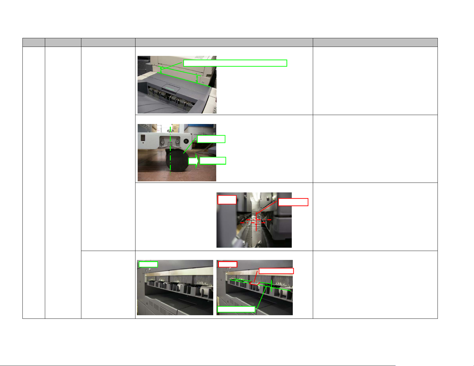
A. Confirm that the Finisher is installed horizontally (the height of its front side and that of its rear side are the
same
.
The length of the arrows should be the same.
B. To keep the installation height of the Finisher stable, it is preferable that the casters are faced to the equipment
side.
Caster
㪜quipment side
C. When installing the Finisher in the equipment, make sure that the height of the Finisher is proper. If it is not, the
e Unit exit Mylar may be deformed, and thus the deformed Mylar may obstruct the paper transportpath.
Brid
Improper
case
Installation height
- Note that the height should be different between the cases when the Finisher
is installed in e-STUDIO281c/351c/451c and when installed in eSTUDIO352/452 or e-STUDIO2500c/3500c/3510c.
- Confirm the height every time you move the equipment.
2. Bridge Unit exit Mylar deformed
Check if the Mylar attached to the exit of the Bridge Unit is deformed and obstructing the paper transport path.
Correct it if deformed.
Normal Abnormal
Deformed Mylar
Paper transport path
㪈
㪄㩷Note that the height should be different between the cases when the Finisher
is installed in e-STUDIO281c/351c/451c and when installed in eSTUDIO352/452 or e-STUDIO2500c/3500c/3510c.
Page 4
Error code Phenomenon Possible cause Items to confirm / Countermeasures Precautions / Remarks
EA20
- Paper jams at the
entrance section of
the Finisher (or the
Hole Punch Unit)
- Folded paper edge
- Paper jams C2in the
buffer tray section
- C2Paper exit
problems on the
finishing tray
3. Improper connection between
the equipment and the Hole
Punch Unit
(Paper is not properly transported
from the equipment to the Hole
Punch Unit if they are not
connected correctly.)
4. False operation of the buffer
guide
(Paper jams may occur if the load
is applied to the buffer guide
during its opening or closing
movement.)
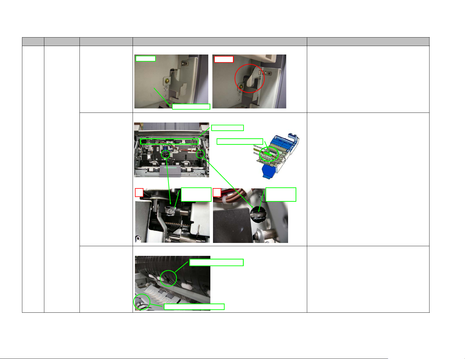
When the Hole Punch Unit is installed, check if the connection point is shifted forward or backward.
Normal
Hole Punch Unit
Remove the stationary tray and apply grease "Molykote EM-30L" (the size of 5 grains of rice) to the buffer guide
shaft.
Abnormal
Buffer roller
Buffer guide shaft
5. False operation of the entrance
sensor or the transport sensor
(An error may occur when the
entrance sensor or the transport
sensor does not perform proper
detection.)
㪸
A. Check if the wires of the entrance sensor or the transport sensor are being caught or short circuited, or any of
their connectors is disconnected.
Molykote EM-30L
(the size of 5
grains of rice)
Transport sensor actuator
Entrance sensor actuator
㪹
㪉
Molykote EM-30L
(the size of 5
grains of rice)
a: Slide the buffer guide to the center and lubricate between the shafts of the
front buffer guide.
b: Slide the buffer guide forward or backward and lubricate between the shafts
of the rear buffer guide.
* Be sure to lift up the buffer roller before sliding the guide.
If the entrance sensor does not retract quickly, replace the spring
with a new one P/N 6LB09015000 SPG-FEED-SNSR-1.
Page 5
Error code Phenomenon Possible cause Items to confirm / Countermeasures Precautions / Remarks
p
EA20
- Paper jams at the
entrance section of
the Finisher (or the
Hole Punch Unit)
- Folded paper edge
- Paper jams C2in the
buffer tray section
- C2Paper exit
problems on the
finishing tray
5. False operation of the entrance
sensor or the transport sensor
(An error may occur when the
entrance sensor or the transport
sensor does not perform proper
detection.)
6. False operation of the paper
exit guide
(An error may occur when the
paper exit guide is not operating
properly because paper may
remain on the finishing tray or not
exit properly during sort or
stapling exit.)
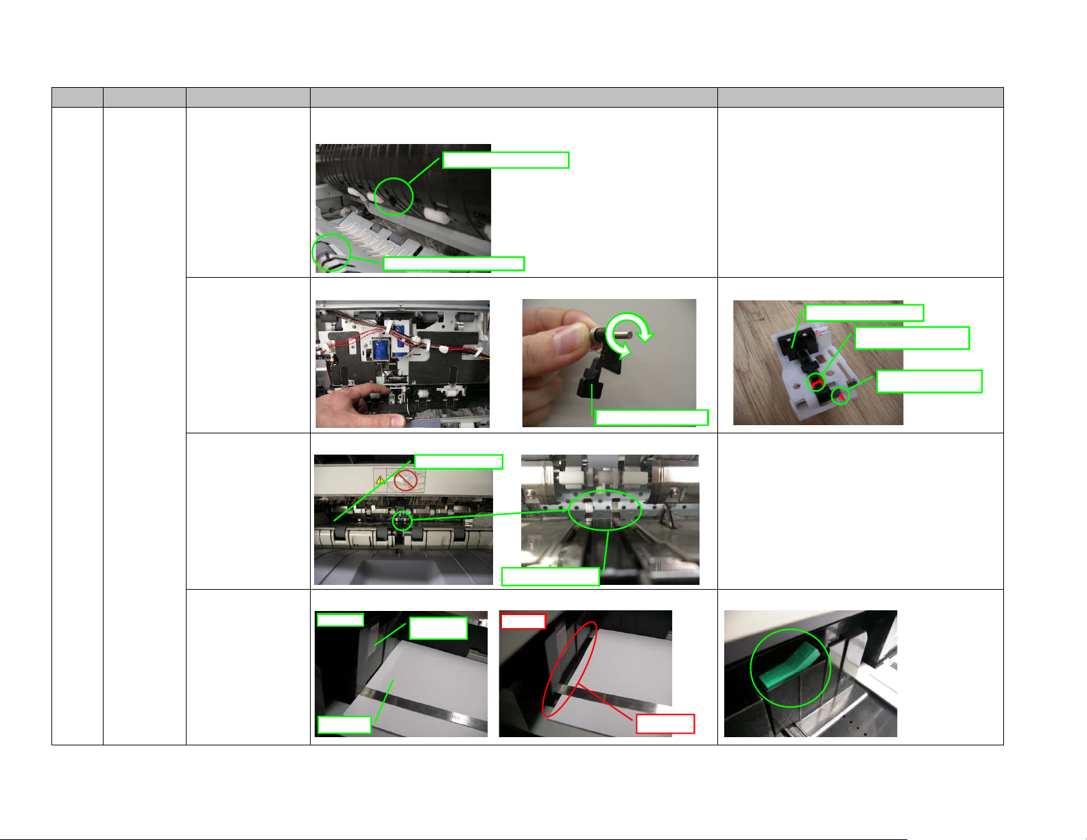
B. Check if the actuators of the entrance sensor and the transport sensor are operating smoothly. If they are not,
remove the actuator and check if there is any paper dust or foreign matter between the shaft and the hole. Clean if
there is.
Transport sensor actuator
Entrance sensor actuator
Operation check of the transport sensor actuator: Rotate the shaft slowly. If the actuator is not rotated together, its
o
eration is normal.
Transport sensor actuator
Replace SPG-SFFD-SUPT-SF (6LB090140) if the paper exit guide is not operating properly.
Finishing tray
Transport sensor actuator
Hook this to the actuator.
Hook this onto the bracket.
Paper exit guide
7. Paper not placed properly in
the drawer
(Paper may be skewed if there is
extra gap between the paper and
the side wall in the drawer and
thus may cause a jam on the
Finisher transport path.)
Normal
Paper
Side wall
Abnormal
Gap
㪊
Be sure to lock the side wall.
Page 6

Error code Phenomenon Possible cause Items to confirm / Countermeasures Precautions / Remarks
EA20
- Paper jams at the
entrance section of
the Finisher (or the
Hole Punch Unit)
- Folded paper edge
- Paper jams C2in the
buffer tray section
- C2Paper exit
problems on the
finishing tray
8. Drive not transmitted from the
gear in the paper transport
section
A. Check if there is any rattling on ASYS-LVR-E-RLR-BUF. If there is, replace ASYB-SFT-EXT-RLR-DRV-BUF,
ASYS-LVR-E-RLR-BUF, GEAR-IDLER-EXT-BUF, GEAR1-EXT-RLR-BUF and GEAR2-EXT-RLR-BUF.
ASYB-SFT-EXT-RLR-DRV-BUF
GEAR1-EXT-RLR-BUF
GEAR-IDLER-EXT-BUF
ASYS-LVR-E-RLR-BUF
GEAR2-EXT-RLR-BUF
Check that there is no rattling.
B. Check if the gear teeth of GEAR-IDLER-EXT-BUF, GEAR1-EXT-RLR-BUF and GEAR2-EXT-RLR-BUF mesh
correctly. If any of them does not mesh correctly, replace ASYB-SFT-EXT-RLR-DRV-BUF, ASYS-LVR-E-RLRBUF, GEAR-IDLER-EXT-BUF, GEAR1-EXT-RLR-BUF or GEAR2-EXT-RLR-BUF.
㪋
ASYB-SFT-EXT-RLR-DRV-BUF
GEAR1-EXT-RLR-BUF
GEAR-IDLER-EXT-BUF
ASYS-LVR-E-RLR-BUF
GEAR2-EXT-RLR-BUF
When replacing, be sure not to scratch the shaft (ASYB-SFT-EXT-RLR-DRVBUF).
LVR-E-RLR-BUF
ASYB-SFT-EXT-RLR-DRV-BUF
Do not scratch this area.
SFT-EXT-RLR-DRV-BUF
Scratch on the shaft
Page 7

Error code Phenomenon Possible cause Items to confirm / Countermeasures Precautions / Remarks
perj
g
Pa
EA40
ammin
(A cover-open error occurs if the
stationary tray is left open
because the stationary tray
opening/closing switch performs
false detection during operation.)
2. Stationary tray opening/closing
switch actuator deformed
(A cover-open error occurs if the
actuator is deformed because the
stationary tray opening/closing
switch cannot be turned and
performs false detection.)
Close the stationary tray securely if it is open.1. Stationary tray left open
Tray closed Tray opened
Stationary tray
Replace PLT-OPEN-SW-BUF if the actuator is deformed.
Actuator
deformed (MJ-1101)
(A cover-open error occurs if the
actuator is deformed because the
front cover switch cannot be
turned and it performs false
detection.)
deformed (MJ-6101)
(A cover-open error occurs if the
actuator is deformed because the
front cover switch cannot be
turned and performs false
detection.)
Replace HNDL-DOOR if the actuator is deformed or damaged.3. Front cover switch actuator
MJ-1101
Actuator
Replace COVER-F-DOOR-P if the actuator is deformed or damaged.3. Front cover switch actuator
MJ-6101
Actuator
㪌
Page 8

Error code Phenomenon Possible cause Items to confirm / Countermeasures Precautions / Remarks
g
EA70
EA60
CC30
CC41
- When more than one
sheet of paper is
loaded on the buffer
tray, the first sheet is
pushed out of the tray
by the second sheet.
- When more than one
sheet of paper is
loaded on the buffer
tray, the leading edge
of the second sheet is
caught and thus a
paper jam occurs.
- When paper is
transported from the
buffer tray to the
finishing tray, the
paper is run on the
front or rear alignment
plate.
- When paper is
loaded on the finishing
tray, the front and rear
alignment plates
excessibly push the
paper.
- When paper is
transported from the
finishing tray to the
movable tray, the
paper exit guide
catches the paper and
thus a motor error
occurs because the
paper cannot exit.
1. Catching pad deformed or
damaged
(Paper is not aligned properly due
to the deformed or damaged
catching pad.)
2. Catching pad link arm
deformed, damaged or removed
(Paper is not aligned properly
because the link arm of the
catching pad is deformed,
damaged or removed.)
3. Improper roller gap on the
buffer roller guide and buffer tray
Check if the catching pad in the Finisher paper exit section is properly attached. Replace it if it is deformed or
ed.
dama
Normal
Catching pad
Check if the catching pad in the Finisher paper exit section is properly attached. If its link arm is deformed,
damaged or removed, replace ARM-SOL-ALIGN (6LB100080).
Abnormal
Facing down
Catching pad link arm
Turn the power OFF. Then check the gap between rollers on the buffer roller guide and the buffer tray while the
buffer roller is left lowered. If the gap does not reach 0.3 mm, replace the buffer roller guides (LVR-E-RLR-BUF)
on both front and rear sides.
Buffer roller guide
Check the gap within the range 7 mm from the edge of the buffer roller guide.
0.3 mm or
Buffer tray
more
Buffer roller guide
Buffer roller
RLR-EXIT-BUFFER
Roller on the buffer tray
RLR-EXIT-TRY
Within the range 7 mm
from the edge
Buffer roller guide
LVR-E-RLR-BUF
㪍
Page 9

Error code Phenomenon Possible cause Items to confirm / Countermeasures Precautions / Remarks
EA70
EA60
CC30
CC41
- When more than one
sheet of paper is
loaded on the buffer
tray, the first sheet is
pushed out of the tray
by the second sheet.
- When more than one
sheet of paper is
loaded on the buffer
tray, the leading edge
of the second sheet is
caught and thus a
paper jam occurs.
- When paper is
transported from the
buffer tray to the
finishing tray, the
paper is run on the
front or rear alignment
plate.
- When paper is
loaded on the finishing
tray, the front and rear
alignment plates
excessibly push the
paper.
- When paper is
transported from the
finishing tray to the
movable tray, the
paper exit guide
catches the paper and
thus a motor error
occurs because the
paper cannot exit.
4. Improper spacing on the edge
section of the buffer roller guide
and the buffer tray upper section
5. Motor bracket deformed
(The bracket of the buffer tray
guide motor or the buffer roller
drive motor is deformed and thus
drive is not transmitted.)
Turn the power OFF and pull the plunger of the buffer roller lift solenoid by hand. Then check the spacing on the
edge section of the buffer roller guide and the buffer tray upper section while the buffer roller is lifted up. If the
edge section of the buffer roller guide is not lower than the buffer tray upper section, replace STAY-BUFFER.
Buffer roller lift solenoid
Normal
STAY-BUFFER
Buffer tray upper section
RLR-EXIT-TRY
Buffer roller
RLR-EXIT-BUFFER
Buffer roller edge section
LVR-E-RLR-BUF
If the buffer tray guide motor bracket (HLDR-TRAY-BUF) or the buffer roller drive motor bracket (HLDR-MOTRBUFFER) is deformed, replace it.
Buffer tray
- If the joint surfaces of the stationary tray and the rear lower cover (or the
control panel unit) are shifted 4 mm or more, the motor bracket may be
deformed.
- Do not hold the stationary tray when unpacking.
Buffer roller drive motor
Normal
Buffer tray guide motor
Abnormal
A gap appears due to the
deformed bracket.
㪎
Page 10

Error code Phenomenon Possible cause Items to confirm / Countermeasures Precautions / Remarks
EA70
EA60
CC30
CC41
- When more than one
sheet of paper is
loaded on the buffer
tray, the first sheet is
pushed out of the tray
by the second sheet.
- When more than one
sheet of paper is
loaded on the buffer
tray, the leading edge
of the second sheet is
caught and thus a
paper jam occurs.
- When paper is
transported from the
buffer tray to the
finishing tray, the
paper is run on the
front or rear alignment
plate.
- When paper is
loaded on the finishing
tray, the front and rear
alignment plates
excessibly push the
paper.
- When paper is
transported from the
finishing tray to the
movable tray, the
paper exit guide
catches the paper and
thus a motor error
occurs because the
paper cannot exit.
6. STAY-BUFFER deformed Remove the bracket of the buffer roller lift solenoid. Then check that STAY-BUFFER is not deformed using a
7. Improper installation of
alignment plates
scale or other straight tool. Replace it if it is deformed.
STAY-BUFFER
Scale
AbnormalNormal
A gap appears if it is deformed.
If the front or rear alignment plate is removed or its installation is improper, reinstall it. (The alignment plates must
not be risen even if they are tilted to the right or left.)
Alignment plate
Rising of the plate
8. Stack transport motor belt out
of gear
If the stack transport motor belt is loose, retighten it, or replace the motor bracket (BRKT-MOTR-SF) to retighten
the belt.
㪏
Page 11

Error code Phenomenon Possible cause Items to confirm / Countermeasures Precautions / Remarks
p
pap
EA70
EA60
CC30
CC41
- When more than one
sheet of paper is
loaded on the buffer
tray, the first sheet is
pushed out of the tray
by the second sheet.
- When more than one
sheet of paper is
loaded on the buffer
tray, the leading edge
of the second sheet is
caught and thus a
paper jam occurs.
- When paper is
transported from the
buffer tray to the
finishing tray, the
paper is run on the
front or rear alignment
plate.
- When paper is
loaded on the finishing
tray, the front and rear
alignment plates
excessibly push the
paper.
- When paper is
transported from the
finishing tray to the
movable tray, the
paper exit guide
catches the paper and
thus a motor error
occurs because the
paper cannot exit.
10. Abnormalities in paper
transport section
11. Insufficient ejection of
front/rear transport roller
12. Wrong operation by users
during printing
Check if there is any scratch, foreign matter, paper dust or remained paper that disturb the paper transport in the
er transport section. Remove if any.
Paper transport
section
If the front and rear transport rollers are not ejected from the transport guide at 0.5 mm or more, replace the
trans
ortguide(GUIDE-FEED-LOW).
0.5 mm or more
Front transport roller
Transport guide
An EA70 error may occur if paper exit is disturbed during printing.
㪹㪸
Rear transport roller
㪐
Page 12

Error code Phenomenon Possible cause Items to confirm / Countermeasures Precautions / Remarks
EAE0 1. Loose connection
Paper jamming A. Check if the interface cable of the Finisher is connected securely. Reconnect it if not.
(Loose connection may cause
false operation or detection.)
Interface cable
B. Check if the connectors (CN12 and CN14) of the Finisher control PC board are connected securely. Reconnect
them if not.
Connector
C. Check if the connectors (CN1 and CN2) of the CNV board are connected securely and the locking support is
installed properly. Reconnect them if not.
Locking support
2. Movable tray paper exist
sensor harness (HRNS-SFTTRY)
short circuited
(Loose connection may cause
false operation or detection.)
Connector
Check if the harness (HRMS-SFTTRY) of the movable tray paper exist sensor is short circuited or if its wiring is
proper. Replace the harness if it is short circuited.
Abnormal
HRNS-SFTTRY (6LB12426000)
㪈㪇
The harness wiring must be under the screw and inside of the Mylar, and the
harness must be wired along with the groove of the plate as shown on the left.
Be sure that the harness is covered by the Mylar.
Page 13

Error code Phenomenon Possible cause Items to confirm / Countermeasures Precautions / Remarks
(
)
y
CB31
- The movable tray is
lifted up after the
power is turned ON.
An error occurs when
it stops at the upper
limit position.
(Initialization does not
finish.)
- The movable tray is
lowered after the
power is turned ON.
An error occurs before
it is lowered to the
specified position.
Initialization finishes.
tray paper-full sensor due to its
deformed/damaged actuator (The
actuator not ejected)
2. False detection caused by the
removed actuator spring of the
movable tray paper-full sensor
(The actuator not ejected)
If the actuator cannot be ejected due to its deformation or damage, replace ACTR-01-SNSR-VER01-TRAY.1. False detection of the movable
Normal
Reinstall SPG-ACTR-01-TRAY if it is removed.
Normal
Abnormal
Not ejected
Abnormal
Not ejected
3. Improper installation of the
movable tray
(An error occurs if the actuator of
the movable tray paper-full sensor
cannot be pushed due to the
improper installation of the
movable tray.)
The movable tray may not be installed properly (the stay of the movable tray may run on the boss). Reinstall the
movable tra
Normal
.
Movable tray stay
Screwed
Abnormal
Run on the boss
㪈㪈
Page 14

Error code Phenomenon Possible cause Items to confirm / Countermeasures Precautions / Remarks
CB31 An error occurs
because the movable
tray cannot be lowered
(or lifted up) to the
specified position after
printing operation.
1. The movable tray cannot be
lowered or lifted up because the
load is applied to the movable tray
by the contact of the tray and
COVER-RAIL-FRONT (or
COVER-RAIL-REAR).
Check if the inner hooks of COVER-RAIL-FRONT and COVER-RAIL-REAR are properly latched. Reinstall them if
not.
Abnormal
The movable tray and COVERRAIL-FRONT contact.
COVER-RAIL-REAR
COVER-RAIL-FRONT
㪈㪉
Page 15

Error code Phenomenon Possible cause Items to confirm / Countermeasures Precautions / Remarks
)
)
CC41
EA20
EA40
EA70
- Paper jams at the
entrance section of
the Finisher (or the
Hole Punch Unit)
- Folded paper edge
- Improper closing of
the stationary tray
1. Motor bracket deformed
(The bracket of the buffer tray
guide motor or the buffer roller
drive motor is deformed and thus
drive is not transmitted.)
If the buffer tray guide motor bracket (HLDR-TRAY-BUF) or the buffer roller drive motor bracket (HLDR-MOTRBUFFER
is deformed, replace it.
Buffer tray guide motor
Buffer roller drive motor
- If the joint surfaces of the stationary tray and the rear lower cover (or the
control panel unit) are shifted 4 mm or more, the motor bracket may be
deformed.
- Do not hold the stationary tray when unpacking.
2. Improper installation height
(Paper is not properly transported
from the equipment to the
Finisher if each height is
improper.)
Normal
A gap appears due to the
deformed bracket.
A. Confirm that the Finisher is installed horizontally (the height of its front side and that of its rear side are the
.
same
The length of the arrows should be the same.
B. To keep the installation height of the Finisher stable, it is preferable that the casters are faced to the equipment
side.
Equipment side
Abnormal
Caster
- Note that the height should be different between the cases when the Finisher
is installed in e-STUDIO281c/351c/451c and when installed in eSTUDIO352/452 or e-STUDIO2500c/3500c/3510c.
- Confirm the height every time you move the equipment.
㪈㪊
Page 16

Error code Phenomenon Possible cause Items to confirm / Countermeasures Precautions / Remarks
quip
CC41
EA20
EA40
EA70
- Paper jams at the
entrance section of
the Finisher (or the
Hole Punch Unit)
- Folded paper edge
- Improper closing of
the stationary tray
3. Tilted Finisher
(Paper is not properly transported
from the equipment to the
Finisher if the Finisher is tilted.)
If the Finisher is tilted as shown below, adjust the height of each caster to make the Finisher horizontal to the
ment.
e
Normal
Abnormal
Caster
If the Finisher is tilted, the fixing screw of the Bridge Unit and the stationary tray
may be contacted when the stationary tray is opened or closed.
Bridge Unit fixing screw
4. Improper exit of large paper Secure enough space for drawing out the sub-tray when installing the Finisher. If the Finisher is installed as
5. Improper connection between
the equipment and the Hole
Punch Unit
(Paper is not properly transported
from the equipment to the Hole
Punch Unit if they are not
connected correctly.)
shown in the picture below, the trailing edge of large paper may be jammed when it is exiting.
Sub-tray
Wall
When the Hole Punch Unit is installed, check if the connection point is shifted forward or backward.
Normal
Hole Punch Unit
Abnormal
㪈㪋
Be sure to draw out the sub-tray when large paper is used. Otherwise false
stacking, paper dropping or an EA70 error may occur.
Page 17

MJ-1101 Service Manual Addendum Version 01
 Loading...