


Copyright-2008 Toshiba America Business Solutions, Inc. (TABS). This publication contains proprietary and confidential
information retained for reference purpose by authorized TABS dealers. Unauthorized use of this information is prohibited.
TABS makes no express or implied warranty, including implied warranties of merchantability for a particular purpose, with regard
to this technical publication and disclaims any claim arising by reason of the possession or use thereof.
MJ-1027/1028
Service Manual Addendum
Supplement to the Troubleshooting
Section

Overview
This is a collection of troubleshooting hints that TABS has received during our dealer visits,
communication that we have had from technicians, and information from TABS Technical
Specialists. This list is not exhaustive and as usual the Service Manual should always be used
as a reference.
Contents
Contents ........................................................................................................................................................ 2
1. EA20 Paper Transport Stop Jam ............................................................................................................ 3
2. CB30 Tray Lift Abnormality ................................................................................................................... 3
3. CBEO Paper Folding Motor Abnormality .............................................................................................. 4
4. CB90 Paper Pushing Plate Motor Abnormality ..................................................................................... 5
5. Limitless Copies ..................................................................................................................................... 6
6. CB80 without hole punch installed (Backup RAM Data Abnormality) .................................................. 6
7. CB80 with hole punch installed (Backup RAM Data Abnormality) ....................................................... 6
8. Abnormal Noise when exit tray lowers ................................................................................................. 8
9. CB10 Feed Motor Abnormality ............................................................................................................. 8
10. Intermittent Stapling ......................................................................................................................... 8
11. Mis-Stapling ...................................................................................................................................... 8
12. Adjustments that must be done when boards are replaced ............................................................ 8
2
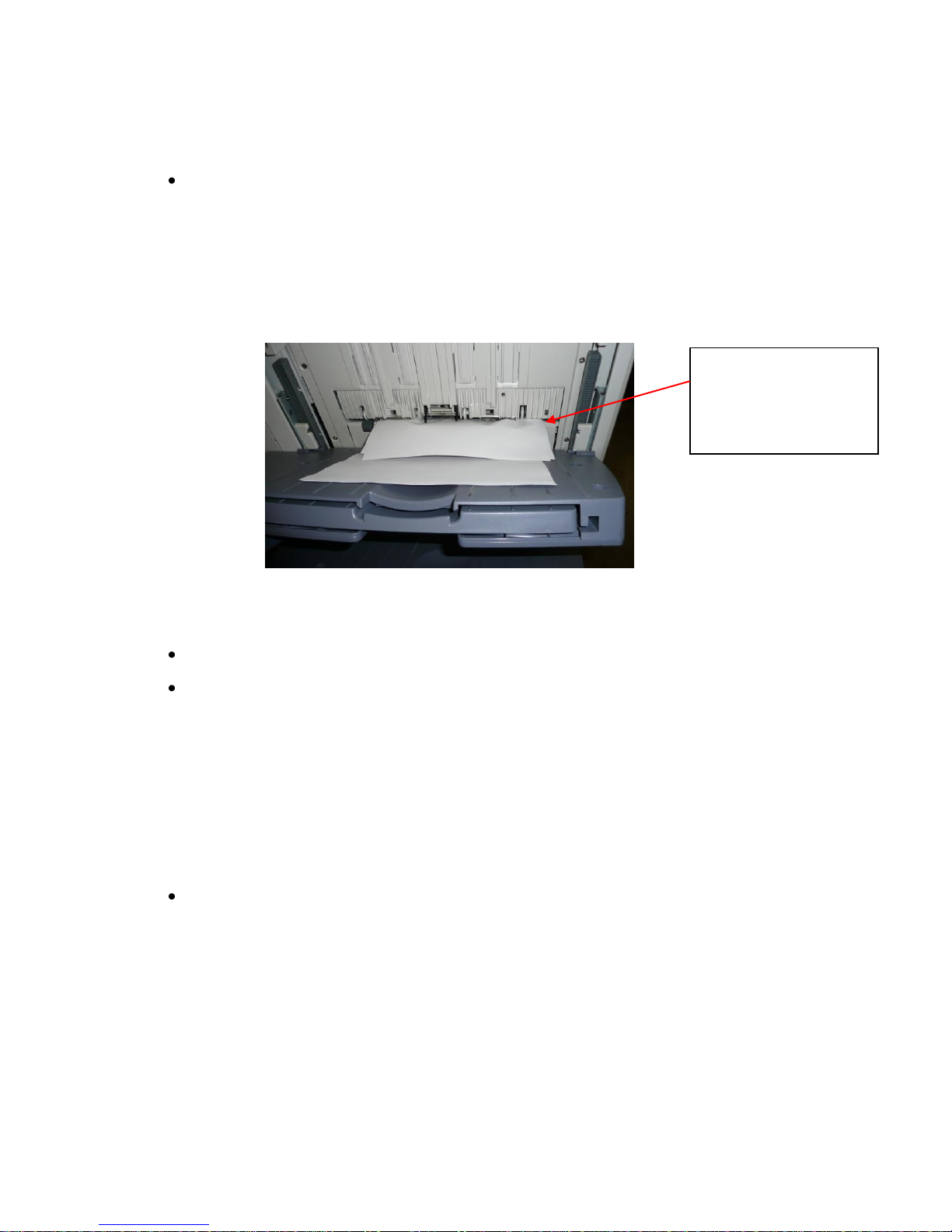
1. EA20 Paper Transport Stop Jam
Paper buckled due to
guide plate not being
lowered by escape
solenoid
There are a couple of areas that should be looked at when EA20 jamming is occurring.
Check for proper operation of Escape Solenoid (SL6) (part number 4402962760
SOLENOID).
If the Escape Solenoid does not operate properly then an EA20 jam could occur (see
Figure 1). The items to check for include:
o Binding of linkage
o Sticking of plunger
o Defective solenoid
Figure 1
Check the proper return operation of the buffer sensor (PI14).
We have had reports that either the first (M1) or second (M8) feed motors (part
number 6LE67833000 MOTR.S-FEED) could fail. The reports from the field are that
both motors need to be replaced at the same time. The reports state that replacing
one motor does not solve the problem and that both need to be replaced at the same
time.
2. CB30 Tray Lift Abnormality
There are a couple of causes of CB30, one is intermittent and the other is constant.
Intermittent
It has been noted in the field that an intermittent CB30 bin lift motor error may occur;
it usually occurs when the lower bin is driving. The cause is linked to the tie wraps on
the harness being too tight (see Figure 2). Over time, with the bins moving up and
down, damage occurs to the harness resulting in this error. As deemed necessary,
remove the cable ties. However, if the wires have already been damaged you may
need to replace the harness. (upper part number: 4G30851000; lower part number:
4G30852000 CABLE-TRAY)
3

Figure 2
Constant
o Check the tray lift motor(s) (M5, M10) (part number 4K11102000 MOTOR-
DC).
o Check the torque limiter (see item 8 Abnormal Noise when exit tray lowers)
3. CBEO Paper Folding Motor Abnormality
CBE0 relates to a folding motor abnormality. It has been determined that the folding motor
itself can be at fault. If replacing the folding motor (part number 6LE67820000 MOTOR)
does not resolve the problem, the faulty motor could have damaged the saddle stitch control
board (part number 4G30849000 SADDLE-CONT-PCB-ASY); in this instance the board
must also be replaced.
****CAUTION – NEVER REPLACE THE BOARD BEFORE CHANGING THE MOTOR****
4

4. CB90 Paper Pushing Plate Motor Abnormality
CB90 refers to the pusher plate (part number: 4402353400 PLATE) on the saddle stitch and
there can be various causes.
Check the condition of the pusher plate (see Figure 3); it should be completely flat
with no kinks or bends in the lead edge ‘castle’ areas.
Figure 3
Clean and check the pusher plate home sensor (PI15S) – do not exchange sensors
in these finishers as they are not the same (see Figure 4). If you suspect the sensor
is at fault, order and fit the correct sensor.
PI15S Cam Assembly and Spring Bushings (Front)
Figure 4
Check the condition of the cam assembly and that the spring is still attached (see
Figure 4). Also ensure that the bushings on both sides of the pusher plate assembly
are in good condition and not elongated (see Figure 4).
5

5. Limitless Copies
Limitless means the finisher recognizes the height of the stack rather than the number of
sets). To make this modification, set dip switch 5 to the ON position. If you make this
modification, advise the end-user of two things:
1. If many sheets are stacked, it is possible that the stacks may fall from the exit tray.
2. The paper may not stack properly in the finisher tray.
6. CB80 without hole punch installed (Backup RAM Data Abnormality)
If the machine is exhibiting CB80 without a hole punch installed perform the following
adjustments
Tray Height Adjustment (MJ1027/28 Service Manual page 6-1)
Alignment Position (MJ1027/28 Service Manual page 6-1)
When replacing the finisher logic board, there are adjustments that must be performed
otherwise a CB80 error may occur, see item 13 for a list.
7. CB80 with hole punch installed (Backup RAM Data Abnormality)
In addition to the items listed in 6 above, perform Sensor Output Adjustment and Registering
the Number of Holes Adjustment. The MJ1027/28/29 Service Manual does not list these
adjustments; the adjustments are listed in the MJ1017/18 Service Manual page 8-7 (see
Figure 5).
The following adjustments should be run when changing the hole punch board or replacing
any of the sensors in the hole punch unit.
6

Figure 5 – MJ1017/18 Service Manual, Page 8-7
7

8. Abnormal Noise when exit tray lowers
Before Change
After Change
NTN
077
17A
NTN
077
17a
MODEL
P-I
Before Change
After Change
MJ-1027
MJ-1028
7-13
8-13
FC56862000
LIMITER- TORQUE
4A30736000
LIMITER-TORQUE
Sometimes when the paper exit tray lowers an abnormal noise can occur. To prevent the
noise, the grease in the torque limiter has been changed. See the diagram below to
distinguish the new torque limiter from the old one.
9. CB10 Feed Motor Abnormality
When this error occurs check the following items:
One-way bearing located inside the cam shutter (part number 4402350530 CAM-
SHUTTER). This may slip causing the error code. Clean/replace as needed.
Safety Switch (MS3) – The spring may not push hard enough on the actuator; reform
the switch arm to make good contact.
10. Intermittent Stapling
Perform Alignment Position adjustment (MJ1027/28 SM page 6-1). If the alignment is too
tight this may produce a buckle lifting the center of the paper off the stapling tray sensor
(PI4).
11. Mis-Stapling
Check the paddles and make sure they are not worn.
Check that the Paddle Solenoid (SL5) is working and that the paddles rotate during
every copy.
12. Adjustments that must be done when boards are replaced
When replacing boards and some sensors there are certain adjustments that must be done.
The adjustments can be found in Chapter 6 of the SM.
Finisher Controller PCB
8

Height Sensor Adjustment
Alignment Position
Staple Position
Buffer Roller Winding Amount
Height Sensor (PS1)
Height Sensor Adjustment
EEPROM (Q2)
Buffer Roller Winding Amount
Saddle Stitch Controller PCB
Set the new DIPSW1 so that the settings will be the same as those on the old
DIPSW1.
Hole Punch Board
Refer to item 7.
END
9
 Loading...