

Page 1

File No. 31100204
R02032112400-TTEC
Ver01 2002-09
Page 2

General Precautions for Installation/Servicing/Maintenance for the Finisher MJ-1017/1018,
Hole punch unit MJ-6003, Inserter MJ-7001
The installation and service should be done by a qualified service technician.
1. When installing the Finisher MJ-1017/1018, Hole punch unit MJ-6003, Inserter MJ7001 to the Plain Paper Copier, be sure to follow the instructions described in the
“Unpacking/Set-Up Procedure for the MJ-1017/1018/MJ-6003/MJ-7001” booklet which
comes with each unit of the MJ-1017/1018/MJ-6003/MJ-7001.
2. The MJ-1017/1018, MJ-6003, MJ-7001 should be installed by an authorized/qualified
person.
3. Before starting installation, servicing or maintenance work, be sure to turn off and
unplug the copier first.
4. When selecting the installation site, avoid placing the MJ-1017/1018/MJ-7001 and
copier on different levels or inclined floors.
5. When servicing or maintaining the MJ-1017/1018/MJ-6003/MJ-7001, be careful about
the rotating or operation sections such as gears, pulleys, sprockets, cams, belts, etc.
6. When parts are disassembled, reassembly is basically the reverse of disassembly
unless otherwise noted in this manual or other related materials. Be careful not to
reassemble small parts such as screws, washers, pins, E-rings, toothed washers to
the wrong places.
7. Basically, the machine should not be operated with any parts removed or disassembled.
8. Delicate parts for preventing safety hazard problems (such as breakers, thermofuses,
fuses, door switches, sensors, etc. if any) should be handled/installed/adjusted correctly.
9. Use suitable measuring instruments and tools.
10. During servicing or maintenance work, be sure to check the serial No. plate and other
cautionary labels (if any) to see if they are clean and firmly fixed. If not, take appropriate actions.
11. The PC board must be stored in an anti-electrostatic bag and handled carefully using
a wristband, because the ICs on it may be damaged due to static electricity. Before
using the wrist band, pull out the power cord plug of the copier and make sure that
there is no uninsulated charged objects in the vicinity.
12. For the recovery and disposal of used MJ-1017/1018/MJ-6003/MJ-7001s, consumable parts, packing materials, used batteries, and RAM-ICs including litium batteries,
it is recommended that the relevant local regulations/rules.
13. After completing installation, servicing and maintenance of the MJ-1017/1018/MJ-6003/
MJ-7001, return the MJ-1017/1018/MJ-6003/MJ-7001 to its original state, and check
operation.
Page 3
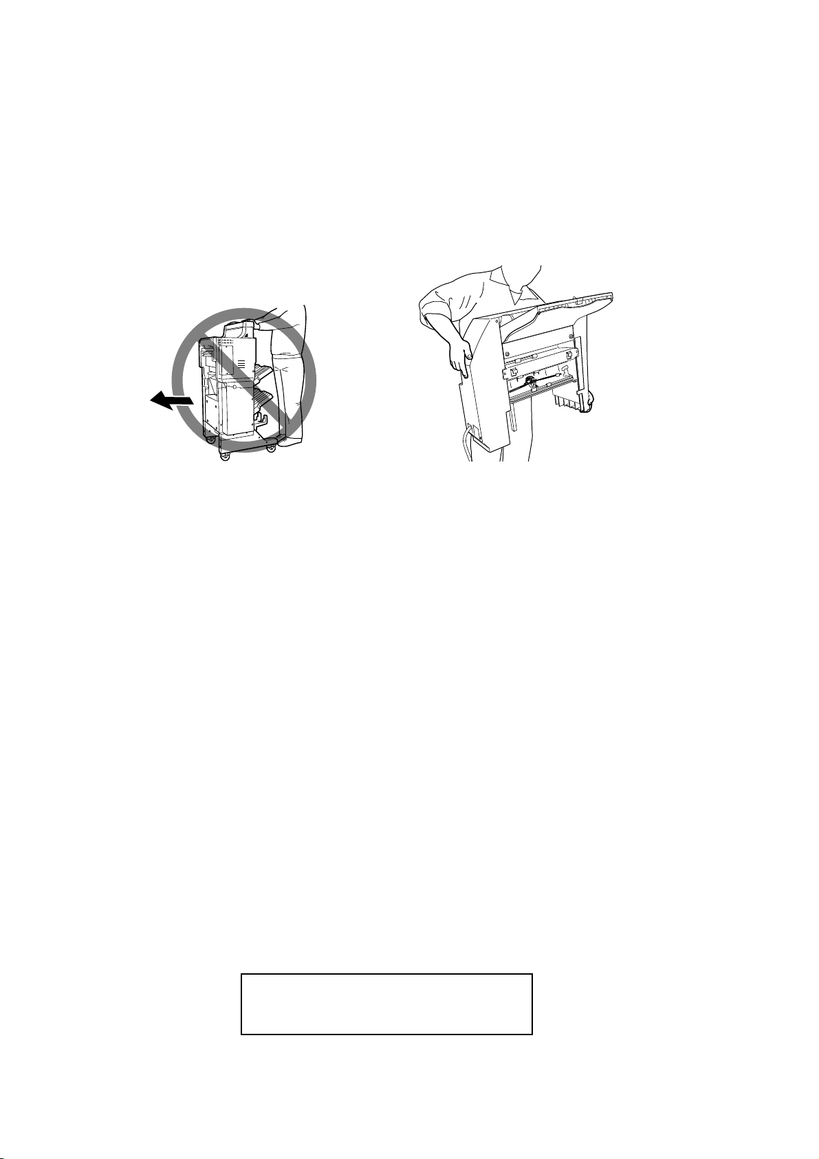
14. When you move the finisher, do not move it in the direction of the arrow as shown in
the figure [A] below otherwise it might fall down. Also, when installing the inserter MJ7001, hold it as the figure [B] below shows in order for your hands not to be caught.
[A] [B]
Copyright © 2002
TOSHIBA TEC Corporation
Page 4

INTRODUCTION
This Service Manual contains basic data and figures for the Finisher (MJ-1017)/Saddle
Finisher (MJ-1018) needed to service the machine in the field.
This manual comprises the following chapters:
Chapter 1 “General Description” introduces the finisher’s features, specifications, and
names of parts, and shows how to operate the finisher.
Chapter 2 “Finisher Unit Basic Operation” discusses the principles of operation used for
the finisher mechanical and electrical systems. It also explains the timing at
which these systems are operated.
Chapter 3 “Saddle Finisher Unit Basic Operation” discusses the principles of operation
used for the saddle stitcher unit’s mechanical and electrical systems. It also
explains the timing at which these systems are operated.
Chapter 4 “Puncher (option) Unit Basic Operation” discusses the principles of operation
used for the puncher unit’s mechanical and electrical systems. It also explains
the timing at which these systems are operated.
Chapter 5 “Inserter (option) Unit Basic Operation” discusses the principles of operation
used for the inserter units mechanical and electrical systems. It also explains
the timing at which these systems are operated.
Chapter 6 “Mechanical System” discusses how the finisher is constructed mechanically,
and shows how it may be disassembled/assembled and adjusted.
Chapter 7 “Maintenance and Inspection” provides tables of periodically replaced parts
and consumables and durables, together with a scheduled servicing chart.
Chapter 8 “Troubleshooting” shows how to troubleshoot possible faults and gives electri-
cal parts arrangement diagrams, LED/check pin diagrams by PCB, and self
diagnosis tables.
“Appendix” contains diagrams showing tables of signals, overall circuit diagrams and tables of solvents/oils.
Descriptions regarding installation are not mentioned in this Service Manual as the
Finisher (MJ-1017)/Saddle Finisher (MJ-1018)’s packing boxes contain Installation Procedures.
The descriptions in this Service Manual are subject to change without notice for product improvement or other purposes, and major changes will be communicated in the form
of Service Information bulletins.
All service persons are expected to have a good understanding of the contents of this
Service Manual and all relevant Service Information bulletins, and be able to identify and
isolate faults in the machine.
i
Page 5

ii
Page 6

CONTENTS
CHAPTER 1 GENERAL DESCRIPTION
I. FEATURES ..................................1-1
II. SPECIFICATIONS .......................1-2
A. Specifications ........................... 1-2
B. Cross Section .........................1-10
III. Using the Machine .....................1-14
A. Removing Paper Jams from the
Finisher Unit ........................... 1-14
B. Supplying the Finisher Unit with
Staples ...................................1-15
C. Removing Staple Jams from the
Finisher Unit ........................... 1-17
D. Removing Paper Jams from the
Saddle Stitcher Unit
(Saddle Finisher) ....................1-18
E. Supplying the Saddle Stitcher
Unit with Staples
(Saddle Finisher) ....................1-20
F. Removing Staple Jams from the
Saddle Stitcher Unit
(Saddle Finisher) ....................1-21
G. Removing Paper Jams from the
Puncher Unit (option) .............1-23
H. Removing Punched Scrap from
the Puncher Unit (option) .......1-25
IV. MAINTENANCE BY THE
USER ........................................1-26
A. Maintenance by the User .......1-26
CHAPTER 2 FINISHER UNIT BASIC OPERATION
I. BASIC OPERATION ....................2-1
A. Outline ......................................2-1
B. Outline of Electrical Circuitry .... 2-2
C. Inputs to and Outputs from the
Finisher Controller PCB ........... 2-4
II. FEED/DRIVE SYSTEM .............2-10
A. Outline ....................................2-10
B. Type of Delivery Paths............ 2-15
C. Feeding and Delivering .......... 2-18
D. Job Offset............................... 2-21
E. Staple Operation ....................2-24
F. Stapler Unit ............................2-32
G. Tray Operation ........................ 2-38
H. Detecting the Height of
Stack on the Tray .................... 2-40
I. Shutter Operation ................... 2-42
J. Buffer Path Operation............. 2-46
K. Detecting Jams ...................... 2-51
III. POWER SUPPLY SYSTEM .......2-56
iii
Page 7

CHAPTER 3 SADDLE STITCHER UNIT
BASIC OPERATION
I. BASIC OPERATION ....................3-1
A. Outline ......................................3-1
B. Electrical Circuitry .................... 3-2
C. Inputs to and Outputs from the
Saddle Stitcher Controller
PCB ..........................................3-3
II. FEEDING/DRIVE SYSTEM ......... 3-8
A. Outline ......................................3-8
III. PAPER OUTPUT
MECHANISM............................. 3-14
A. Outline ....................................3-14
B. Controlling the Inlet
Flappers .................................3-17
CHAPTER 4 PUNCHER UNIT (OPTION)
BASIC OPERATION
I. BASIC OPERATION ....................4-1
A. Outline...................................... 4-1
B. Inputs to and Outputs from
Punch Driver PCB .................... 4-2
II. PUNCH OPERATION ..................4-5
C. Controlling the Movement of
Sheets .................................... 3-21
D. Aligning the Sheets ................ 3-23
E. Controlling the Phase of the
Crescent Roller ...................... 3-26
IV. STITCHING SYSTEM ............... 3-28
V. FOLDING/DELIVERY
SYSTEM ....................................3-31
VI. CHECKING FOR A JAM ........... 3-38
VII. POWER SUPPLY ...................... 3-43
A. Outline ......................................4-5
B. PUNCH OPERATION ...............4-7
C. Horizontal Registration
Operation ............................... 4-11
III. POWER SUPPLY SYSTEM .......4-14
CHAPTER 5 INSERTER UNIT (OPTION)
BASIC OPERATION
I. BASIC OPERATION ....................5-1
A. Outline ......................................5-1
B. Symbols and Layout of
Electric Parts/Diagram of
Signal Blocks............................ 5-2
iv
C. Drive System ............................ 5-6
D. Operation .................................5-8
E. JAM/ERROR DETECTION AND
LED DISPLAY ........................ 5-32
F. CIRCUIT................................. 5-36
Page 8

CHAPTER 6 MECHANICAL CONSTRUCTION
I. FINISHER UNIT .......................... 6-1
A. Externals and Controls .............6-1
B. FEEDING SYSTEM ................. 6-9
C. PCBs ......................................6-13
II. SADDLE STITCHER UNIT ........6-14
A. Externals and Controls ...........6-14
B. SADDLE UNIT ....................... 6-17
C. PCBs ......................................6-27
D. Accessory .............................. 6-28
III. PUNCHER UNIT (OPTION) ...... 6-29
CHAPTER 7 MAINTENANCE AND INSPECTION
I. PERIODICALLY REPLACED
PARTS ......................................... 7-1
A. Finisher Unit ............................. 7-1
B. Saddle Stitcher Unit ................. 7-1
C. Puncher Unit (option) ............... 7-1
D. Inserter (option)........................ 7-1
II. CONSUMABLES AND
DURABLES .................................7-2
A. Externals and Controls ........... 6-29
B. Puncher Driver System .......... 6-30
C. PCBs ......................................6-41
IV. INSERTER UNIT (OPTION) ...... 6-43
A. Exterior Parts ......................... 6-43
B. Feeding Section .....................6-44
C. Drive Section .......................... 6-46
D. Upper Inserter Unit .................6-49
E. Tray Unit .................................6-50
F. Notes for Installing ................. 6-52
A. Finisher Unit ............................. 7-2
B. Saddle Stitcher Unit ................. 7-2
C. Puncher Unit (option) ............... 7-2
D. Inserter (option)........................ 7-2
III. PERIODICAL SERVICING .......... 7-2
IV. FIRMWARE UPDATING
(only for inserter section) .............7-3
CHAPTER 8 TROUBLESHOOTING
I. ADJUSTMENTS .......................... 8-1
A. Electrical System
(finisher unit) ............................ 8-1
B. Electrical System
(saddle stitcher unit) .................8-5
C. Electrical System
(puncher unit (option)) ..............8-7
D. Electric Unit/(Inserter Section
(Optional)) ................................8-9
E. Inserter Section ...................... 8-10
II. ARRANGEMENT OF
ELECTRICAL PARTS ................8-12
A. Finisher Unit ...........................8-12
B. Saddle Stitcher Unit ............... 8-19
C. Puncher Unit (option) .............8-25
D. Light-Emitting Diodes (LED)
and Check Pins by PCB .........8-29
III. TROUBLESHOOTING ............... 8-31
A. Finisher Unit ...........................8-31
B. Saddle Stitcher Unit ............... 8-41
C. Puncher Unit (option) .............8-48
D. Inserter Section (Option) ........ 8-49
v
Page 9

APPENDIX
A. FINISHER UNIT GENERAL
TIMING CHART.......................... A-1
B. SADDLE STITCHER UNIT
GENERAL TIMING CHART........ A-2
C. PUNCHER UNIT (option)
GENERAL TIMING CHART........ A-3
D. INSERTER UNIT (option)
GENERAL TIMING CHART........ A-4
E. SIGNAL AND
ABBREVIATIONS ..................... A-14
F. FINISHER UNIT CIRCUIT
DIAGRAM ................................. A-15
G. SADDLE STITCHER UNIT
CIRCUIT DIAGRAM ................. A-26
H. PUNCHER UNIT (option)
CIRCUIT DIAGRAM ................. A-34
I. INSERTER UNIT (option)
CIRCUIT DIAGRAM ................. A-41
J. SOLVENTS AND OILS ............. A-45
vi
Page 10

CHAPTER 1
GENERAL DESCRIPTION
I. FEATURES ..................................1-1
II. SPECIFICATIONS .......................1-2
A. Specifications............................. 1-2
B. Cross Section .......................... 1-10
III. Using the Machine .....................1-14
A. Removing Paper Jams from the
Finisher Unit............................. 1-14
B. Supplying the Finisher Unit with
Staples .....................................1-15
C. Removing Staple Jams from the
Finisher Unit............................. 1-17
D. Removing Paper Jams from the
Saddle Stitcher Unit
(Saddle Finisher) .....................1-18
E. Supplying the Saddle Stitcher
Unit with Staples
(Saddle Finisher) ..................... 1-20
F. Removing Staple Jams from the
Saddle Stitcher Unit
(Saddle Finisher) ..................... 1-21
G. Removing Paper Jams from the
Puncher Unit (option) ............... 1-23
H. Removing Punched Scrap from
the Puncher Unit (option) ......... 1-25
IV. MAINTENANCE BY THE
USER ........................................1-26
A. Maintenance by the User ......... 1-26
Page 11

CHAPTER 1 GENERAL DESCRIPTION
I. FEATURES
1. Accommodates large quantities of sheets
●
Normally, the finisher holds a stack of sheets 250 mm in height in its two bins (small-size
paper: equivalent to 2000 sheets)/140 mm in height (large-size paper: equivalent to 1000
sheets)
2. Has high paper transportation performance
●
The finisher is capable of handling papers between 60 and 256 gm/m2.
3. Offers a job offset function
●
The finisher has a job offset function for sorting non-stapled stacks of copies.
4. Offers four types of auto stapling
●
The finisher offers a choice of four stapling modes (1-point stapling at rear, diagonal stapling at front, diagonal stapling at rear, 2-point stapling).
5. Uses a buffer roller
●
The use of a buffer roller enables the f inisher to accept copies without interruption from the
host machine even during stapling or offset operation.
6. Has a saddle stitch function (Saddle Finisher MJ-1018)
●
The finisher can staple along the center of paper and fold it in two (up to 15 sheets).
7. Offers a punch function (option)
●
The use of the puncher unit enables the finisher to punch sheets for binders before they are
output. (The puncher unit is capable of handling papers between 60 and 256 gm/m2. It cannot handle special paper, postcards and transparencies.)
8. Insert function (option)
●
Enable the use of special type of paper and printed paper in addition to the staple sorting or
the hole punching mode (Available when the optional staple sorting and the hole punching
mode units are installed.) This paper is not run through fuser (heat).
1-1
Page 12

CHAPTER 1 GENERAL DESCRIPTION
II. SPECIFICATIONS
A. Specifications
1. Finisher Unit
Item
Stacking method
Stacking orientation
Stacking size
Paper weight
Bins
Modes
Stacking capacity
Size mixing
Description
Trays 1 and 2: by lifting tray
Face-down
AB: A3, A4, A4-R, A5-R, B4, B5, B5-R, FOLIO
Inch: LD, LG, LT, LT-R, ST-R, COMPUTER
60 to 256 g/m
2
Trays 1 and 2
Non-sort: trays 1 and 2
Sort: trays 1 and 2
Staple sort: trays 1 and 2
Non sort Small-size
Non staple sort
(Note 1)
Large-size
(Note 1)
Staple sort Small-size
(Note 1)
Large-size
(Note 1)
Size mixing: 74 mm or less (500 sheets)
Staple mixing: 74 mm or less (500 sheets)
250 mm (2000 sheets)
140 mm (1000 sheets)
110 mm/50 sets (750 sheets)
74 mm/50 sets (500 sheets)
(Note 1)
(Note 1)
(Note 2)
(Note 2)
Stacking mixing
Notes:
1. Approximate when computed with reference to 80 g/m
2. Alignment may not be correct if 750 or more small-size sheets are stacked.
3. The accuracy of the stack height is ± 7 mm/0.28 in.
Face-down
2
paper.
Table 1-201
1-2
Page 13

CHAPTER 1 GENERAL DESCRIPTION
Item
Stapling
Stapling position
Stapling capacity
(Note1)
Staple supply
Staples
Staple detection
Manual stapling
Stapling size
Paper detection
Control panel
Display
Description
By rotating cam
See Figure 1-201.
Small-size
Large-size
Special staple cartridge (5000 staples)
Special (STAPLE-700: 3 cartridges of 5000 staples in a package)
Provided
Not provided
1-point diagonal Front A3, B4, A4, A4-R, B5, LD, LG, LT, LT-R,
stapling (diagonal) FOLIO, COMPUTER
1-point Rear A4-R, LT-R, LG, FOLIO
2-point A3, B4, A4, B5, A4-R, LD, LG, LT-R, FOLIO,
Provided
Not provided
Not provided
50 sheets (60 ~ 80 g/m2)
30 sheets (60 ~ 80 g/m2)
Rear A3, B4, A4, B5, LD, LT
COMPUTER
30 sheets (90 g/m2)
15 sheets (90 g/m2)
30 sheets (105 g/m2)
15 sheets (105 g/m2)
Dimensions
(W × D × H)
Weight
Power supply
Maximum power
consumption
740 × 630 × 1023 mm/29.25 × 24.88 × 40.38 in
813 × 630 × 1023 mm/32.13 × 24.88 × 40.38 in
922 × 630 × 1023 mm/36.38 × 24.88 × 40.38 in
995 × 630 × 1023 mm/39.25 × 24.88 × 41.38 in (with Puncher Unit and
Inserter Unit attached)
Finisher (MJ-1017): 42 kg/92.59 lb
Saddle finisher (MJ-1018): 62 kg/136.68 lb
Puncher unit (option): 5.4 kg/11.68 lb
Inserter unit (option): 20 kg/44.09 lb
From host machine (24 VDC, 5 VDC)
170 W or less
(with Puncher Unit attached)
(with Inserter Unit attached)
Note1: Equiv alent of 80 g/m2 paper . Including two sheets of thick stock or cov er (200 ~ 256 g/m2)
Table 1-202
Reference:
The term “small-size” stands for A4, A5-R, B5, LT, ST-R, while the term “large-size” stands for
A3, B4, A4-R, B5-R, LT-R, LD, LG, FOLIO, COMPUTER.
1-3
Page 14
CHAPTER 1 GENERAL DESCRIPTION
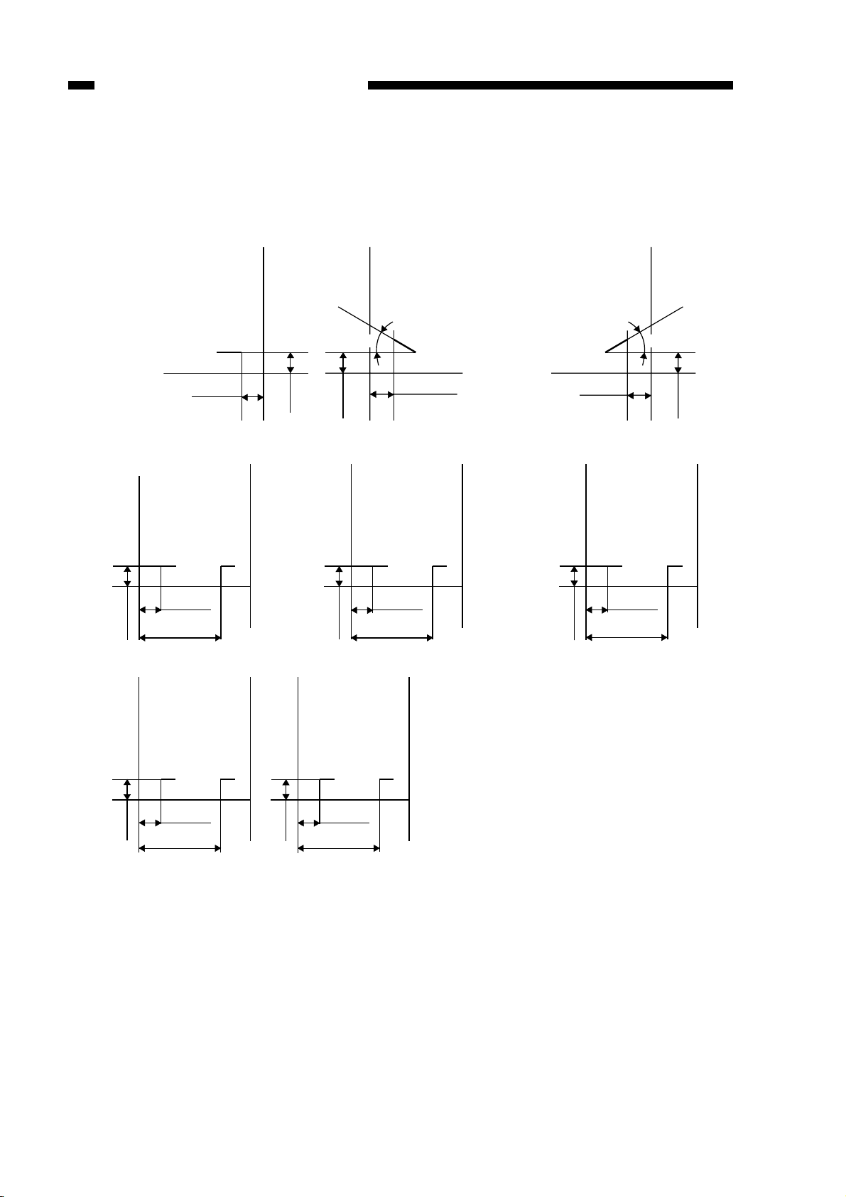
Stapling Positions (finisher unit)
1-point stapling (rear)
Specified paper width
-0.24±0.16in
2-point stapling
A3 and A4
83±4mm/
3.26±0.16in
203±4mm/
5±4mm/
7.98±0.16in
0.2±0.16in
-6±4mm/
5±4mm/
0.2±0.16in
1-point stapling
(diagonal; front)
30˚
4.4±4mm/
-0.17±0.16in
4.4±4mm/
0.17±0.16in
B4 and B5
63±4mm/
2.47±0.16in
183±4mm/
5±4mm/
7.19±0.16in
0.2±0.16in
Specified paper width
-0.24±0.16in
5±4mm/
1-point stapling
(diagonal; rear)
-6±4mm/
LD and LT
74±4mm/
2.9±0.16in
194±4mm/
7.63±0.16in
0.2±0.16in
30˚
4±4mm/
0.16±0.16in
A4-R and FOLIO LT-R and LG
62.5±4mm/
2.46±0.16in
5±4mm/
0.2±0.16in
138.5±4mm/
5.45±0.16in
5±4mm/
0.2±0.16in
62.5±4mm/
2.46±0.16in
144.5±4mm/
5.69±0.16in
Figure 1-201
1-4
Page 15

2. Saddle Stitcher Unit
CHAPTER 1 GENERAL DESCRIPTION
Item
Stapling method
Folding position
Paper size
Capacity
Paper weight
Stacking capacity
Stapling
Folding
Description
Center binding (double folding)
See Figure 1-202.
A3, B4, A4-R, LD, LT-R
W/binding: 1 sheet
W/out binding: 2 to 15 sheets
60 to 105 g/m2 (cover page up to 256 g/m2)
(including single cover page)
(Note 1)
10 sets (stack of 11 to 15 sheets), 20 sets (stack of 6 to 10 sheets),
25 sets (stack of 5 sheets or less)
Stapling position 2 points (center distribution; fixed interval)
Staple accommodation 2000 staples
Staple supply Special cartridge
Staples Special staples (STAPLE-600: 3 cartridges
of 2000 staples in a package)
Staple detection Provided
Manual stapling Not provided
Folding method Roller contact
Folding mode Double folding
Folding position Paper center
Position adjustment Provided
Power supply
From finisher unit
DC24V, DC5V
Power consumption
160 W or less
Note1: Special paper, postcards, transparencies, reproducibles, label paper and hole-punched paper
cannot be handled.
Table 1-203
1-5
Page 16
CHAPTER 1 GENERAL DESCRIPTION
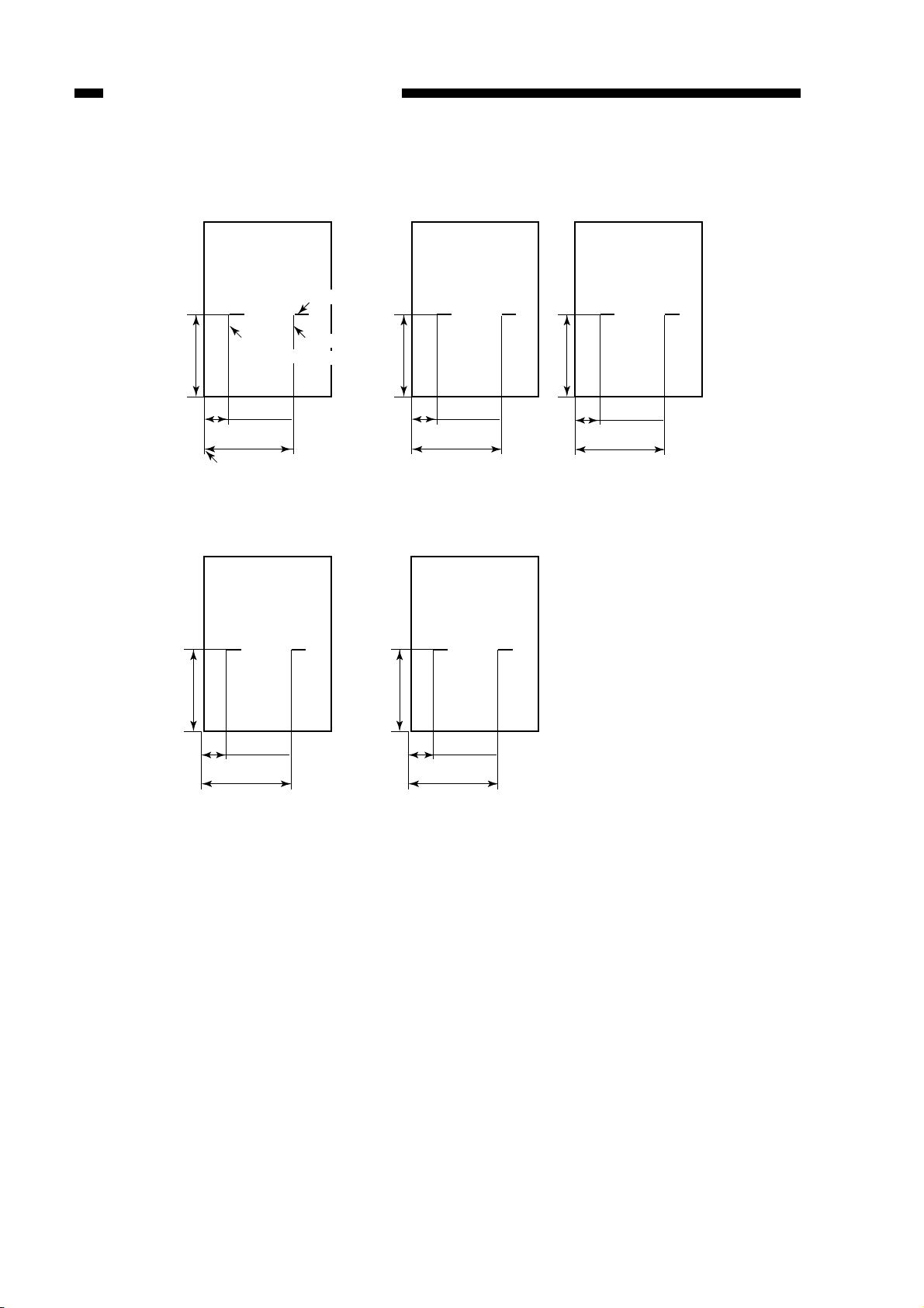
Staple and Folding Position (saddle stitcher unit)
A3
210±1mm/
8.27±0.04in
203±2mm/
8.21±0.08in
Stack front edge
LD
Edge
of staple
83±2mm/
3.48
±0.08in
Staple position
Edge of
staple
B4
182±1mm/
7.17±0.04in
LT-R
63±2mm/
2.7
±0.08in
183±2mm/
7.42±0.08in
A4-R
5.85±0.04in
148.5±1mm/
159.5±2mm/
39.5±2mm/
1.77±0.08in
6.5±0.08in
8.5±0.04in
216±1mm/
74±2mm/
3.14
±0.08in
194±2mm/
7.86±0.08in
5.5±0.04in
139.7±1mm/
42mm/
1.89±0.08in
162±2mm/
6.61±0.08in
Figure 1-202
1-6
Page 17
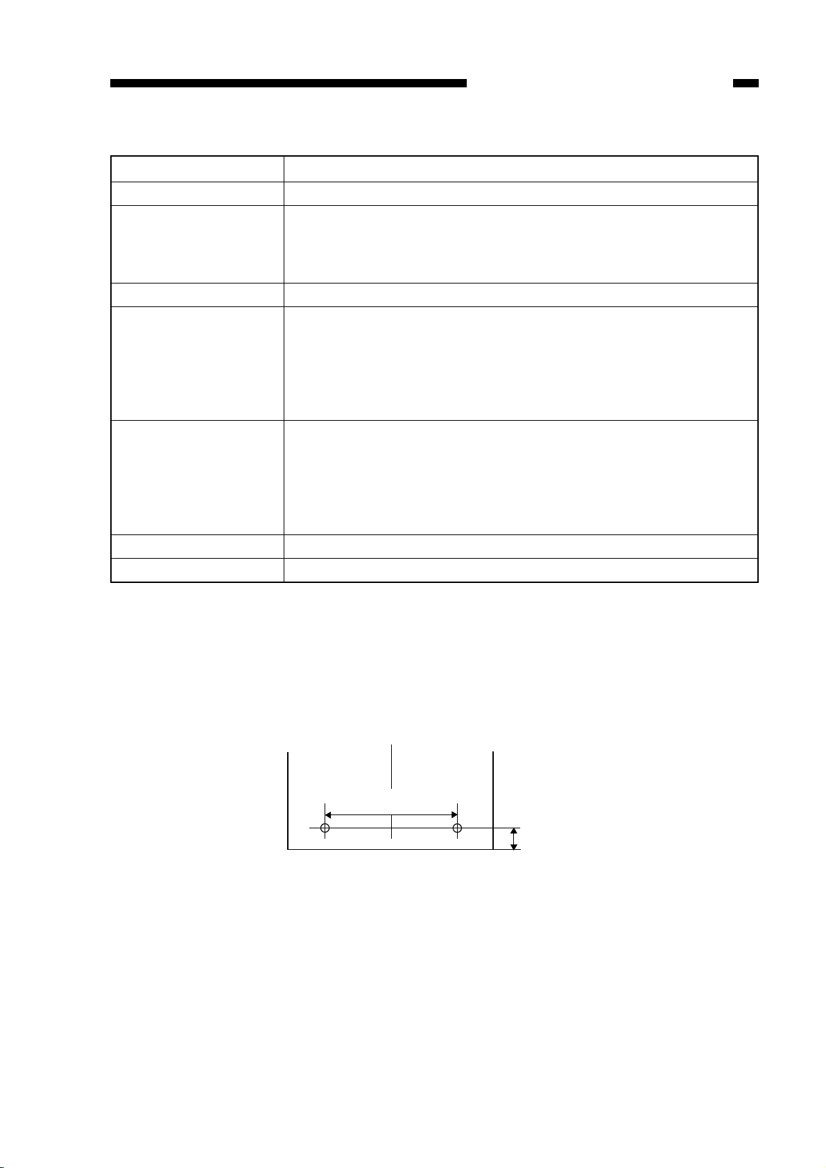
3. Puncher Unit (Option)
12±3 mm/
0.47±0.12 in
80±1 mm/
3.15±0.04 in
[1] 2 holes (Puncher Unit MJ-6003E)
CHAPTER 1 GENERAL DESCRIPTION
Item
Punching method
Paper size
Paper weight
Punched hole diameter
Punched scrap capacity
Power supply
Power consumption
Description
Sequential punching
2 holes (puncher unit MJ-6003E): A3, A4, A4-R, B4, B5, B5-R
2 or 3 holes (puncher unit MJ-6003N): 2 holes/LG, LT-R
3 holes/LD, LT
4 holes (puncher unit MJ-6003F/ 6003S): A3, A4, A4-R (MJ-6003S)
60 to 256 g/m2
(Note 1)
2 holes (puncher unit MJ-6003E): 6.5mm
2 or 3 holes (puncher unit MJ-6003N): 2 holes/8.0mm
2 holes/0.31in
3 holes/8.0mm
3 holes/0.31in
4 holes (puncher unit MJ-6003F/ 6003S): 6.5mm
2 holes (puncher unit MJ-6003E): 5,000 sheets or more (64g/m
equivalent)
2 or 3 holes (puncher unit MJ-6003N): 3,000 sheets or more (75 g/m
equivalent)
4 holes (puncher unit MJ-6003F/6003S): 5,000 sheets or more (80 g/m
equivalent)
From finisher unit (24 VDC, 5 VDC)
120 W or less
2
2
2
Note1: Transparencies, reproducibles, label paper, postcards and hole-punched paper cannot be handled.
Hole position (Puncher Unit)
Figure 1-203-1
1-7
Page 18
CHAPTER 1 GENERAL DESCRIPTION
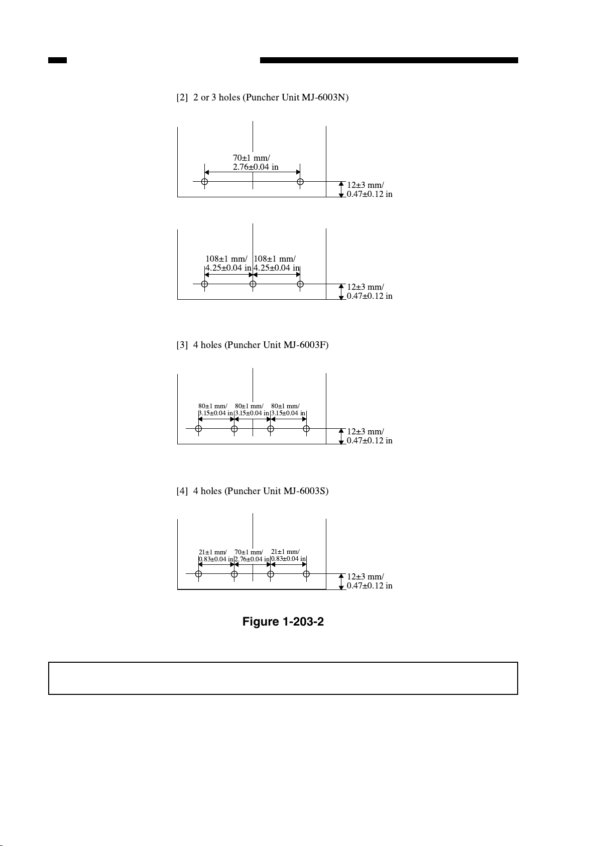
[2] 2 or 3 holes (Puncher Unit MJ-6003N)
70±1 mm/
2.76±0.04 in
12±3 mm/
0.47±0.12 in
108±1 mm/
4.25±0.04 in
108±1 mm/
4.25±0.04 in
[3] 4 holes (Puncher Unit MJ-6003F)
80±1 mm/
3.1 5±0.04in
80±1 mm/
3.1 5±0.04in
80±1 mm/
3.1 5±0.04in
[4] 4 holes (Puncher Unit MJ-6003S)
12±3 mm/
0.47±0.12 in
12±3 mm/
0.47±0.12 in
1-8
21±1 mm/
0.83±0.04 in
70±1 mm/
2.76±0.04 in
21±1 mm/
0.83±0.04 in
12±3 mm/
0.47±0.12 in
Figure 1-203-2
Specifications are subject to change without notice.
Page 19

4. Inserter section
CHAPTER 1 GENERAL DESCRIPTION
Item
Paper size
Paper weight
Special papers
Laded number of
papers
A3, A4, A4-R, B4, B5, FOLIO, LD, LG, L T, LT -R
60g/m2 ~ 256g/m2 (16 lb. ~ 140 lb. Index)
OHP film, color paper (coated paper), hole-punched paper
100 at maximum for papers less than 80g/m2, number of papers up to 12mm
of laden height for papers more than 80g/m
* less than 60% of the above quantities for special papers
Inserter size
Inserter weight
533 × 612 × 1072mm (21 × 24.13 × 42.38 in) (W × D × H)
Approx. 20kg
* NOTE: Refer to 1-7, 8 for the hole position
Details
(*NOTE)
2
Table 1-204
1-9
Page 20
CHAPTER 1 GENERAL DESCRIPTION
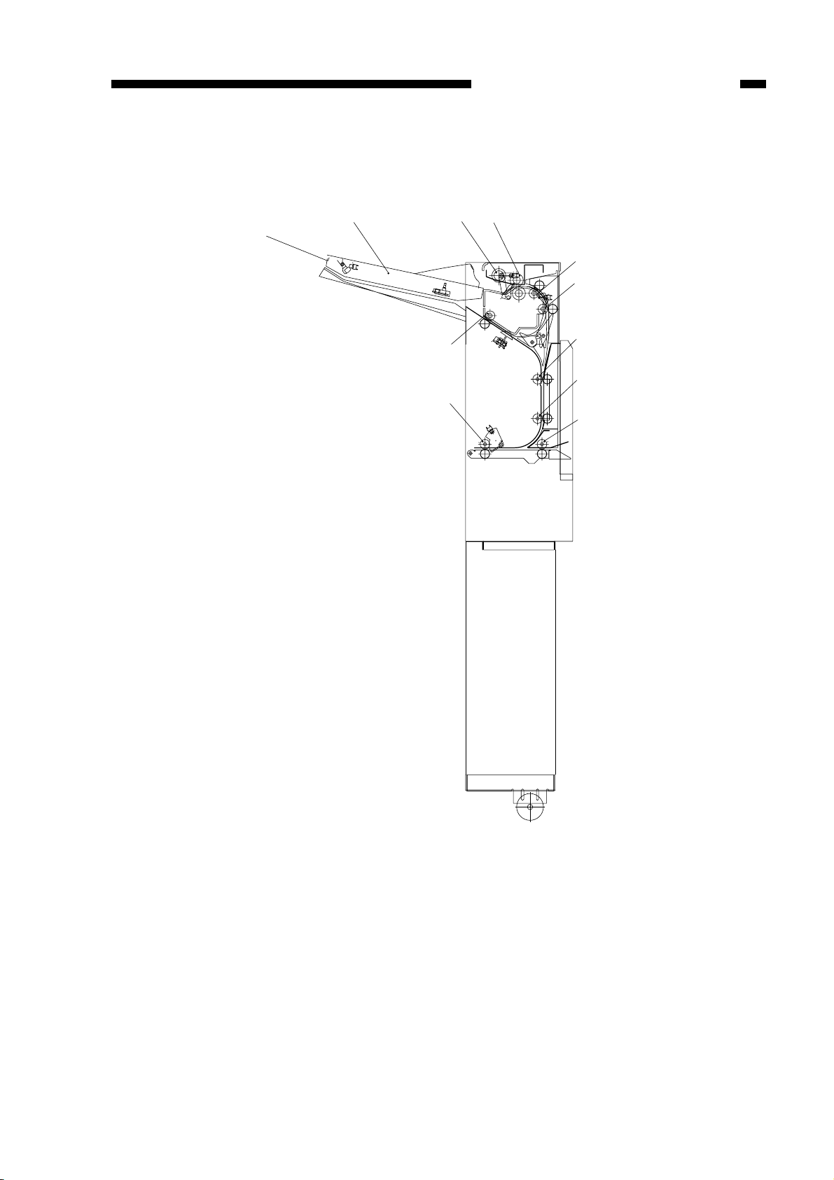
B. Cross Section
1. Finisher Unit
[1] [2] [3] [4] [5] [6] [8]
[7] [10] [11][9]
1-10
[1] Tray 1/2
[2] Shutter
[3] Deli v ery roller
[4] Swing guide
[5] Feed roller 2
[6] Height sensor
[7] Wrap flapper
[8] Buffer roller
[9] Buffer inlet flapper
[15][17][16] [14] [13] [12]
[10] Saddle stitcher flapper
[11] Inlet feed roller
[12] Feed roller 1
[13] Vertical path
[14] Stapler
[15] Feed belt
[16] Tray lift motor
[17] Saddle stitcher unit
(saddle finisher MJ-1018)
Figure 1-204
Page 21
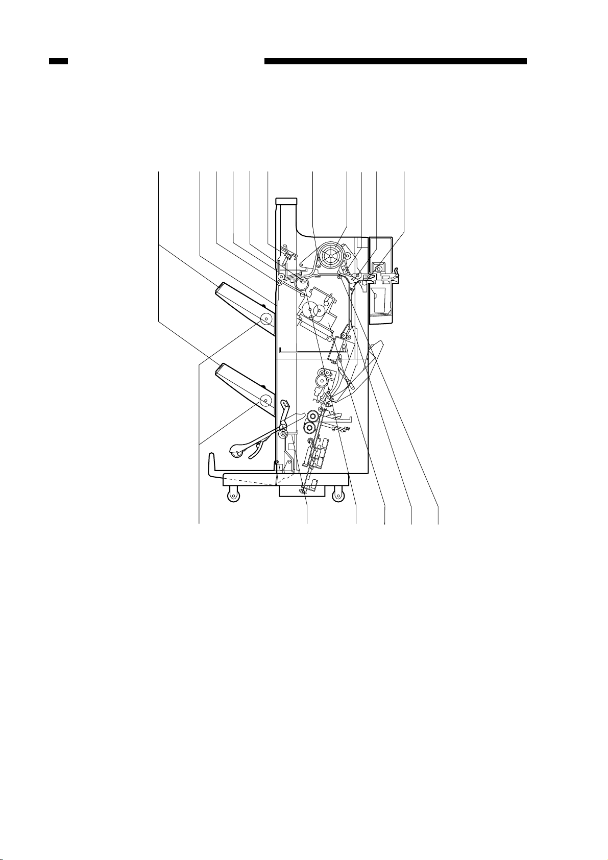
2. Saddle Stitcher Unit
CHAPTER 1 GENERAL DESCRIPTION
[6]
[5]
[4]
[3]
[2]
[1]
[7]
[8]
[9]
[10]
[11]
[12]
[1] Guide plate
[2] Pa per folding roller
[3] Deli v ery guide plate
[4] Holding roller
[5] Stitcher (front, rear)
[6] Inlet roller
[7] No.1 flapper
[8] No. 2 flapper
[9] Stitcher mount
[10] Paper pushing plate
[11] Crescent roller
[12] Paper positioning plate
Figure 1-205
1-11
Page 22
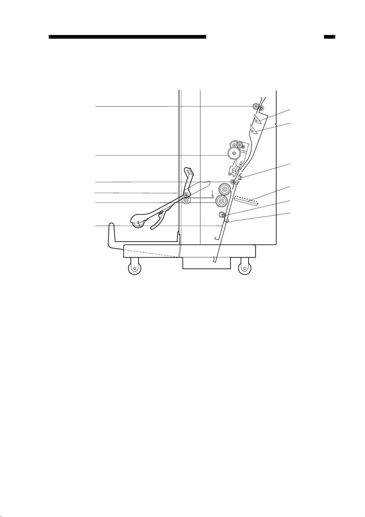
CHAPTER 1 GENERAL DESCRIPTION
3. Puncher Unit (option)
[1]
[2]
[3]
[4]
[1] Punch motor
[2] Cam
[3] Hole puncher (Punch blade)
[4] Die
[5] Photosensor PCB
[5]
[6]
[7]
[8]
[9]
[6] LED PCB
[7] Horizontal registration motor
[8] Scrap full detector PCB unit
[9] Punched scrap container
1-12
Figure 1-206
Page 23
4. Inserter section (optional)
[1]
[10]
[9]
CHAPTER 1 GENERAL DESCRIPTION
[3]
[2]
[4]
[5]
[6]
[7]
[8]
[1] Tray
[2] Pickup roller
[3] Feed roller
[4] Transport roller 1
[5] Transport roller 2
[6] Transport roller 3
[7] Transport roller 4
[8] Transport roller 5
[9] Transport roller 6
[10] Reverse roller
Figure 1-207
1-13
Page 24
CHAPTER 1 GENERAL DESCRIPTION
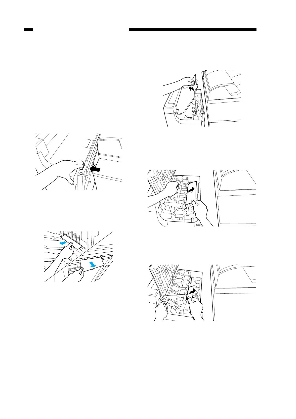
III. Using the Machine
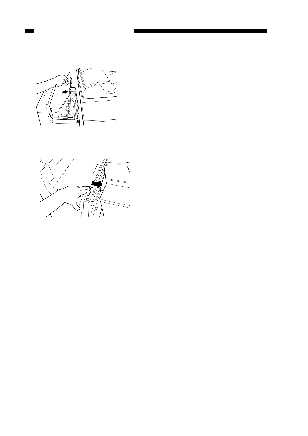
A. Removing Paper Jams
from the Finisher Unit
If the host machine indicates the finisher
paper jam message, perform the following to
remove the jam.
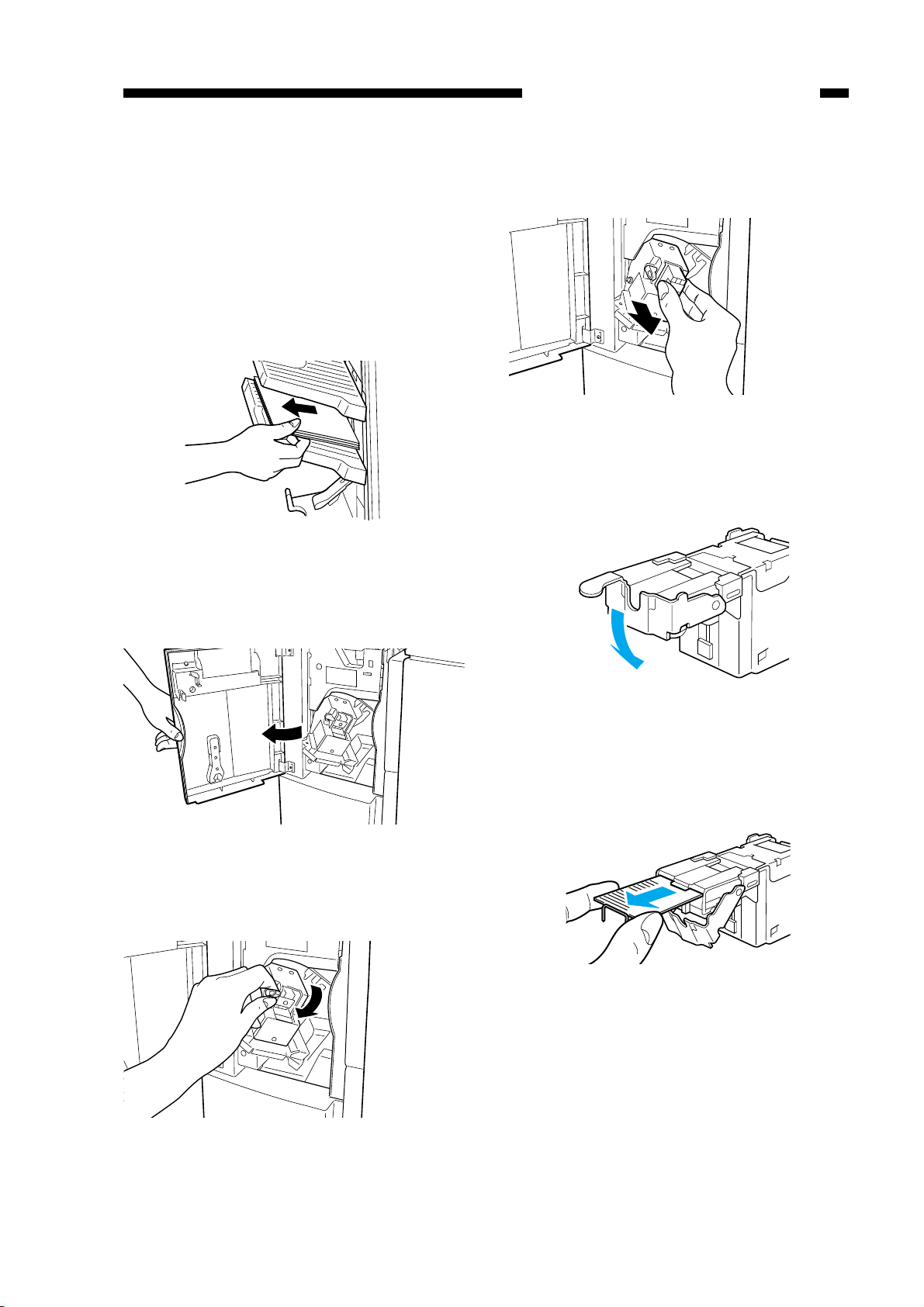
1) Holding the finisher unit as shown, move
it to detach it from the host machine.
3) Open the upper cover, and check the inside of the finisher.
Figure 1-303
4) Lift the buffer roller co ver , and remove the
jam.
Figure 1-301
2) Remove any jam visible from the outside.
Figure 1-302
Figure 1-304
5) Lift the buffer roller, and remove the jam.
Figure 1-305
1-14
Page 25
CHAPTER 1 GENERAL DESCRIPTION
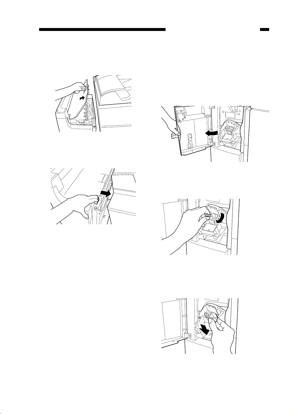
6) Return the buffer roller and the b uffer roller
cover to their original positions, and close
the upper cover.
Figure 1-306
7) Connect the finisher to the host machine.
B. Supplying the Finisher
Unit with Staples
If the host machine indicates the finisher
unit staple supply message, perform the following to supply it with staples.
1) Open the front cover.
Figure 1-308
2) Shift down the blue lever.
Figure 1-307
8) Operate as instructed on the display.
Figure 1-309
3) When the staple cartridge has slightly slid
out, hold and pull it out.
Figure 1-310
1-15
Page 26
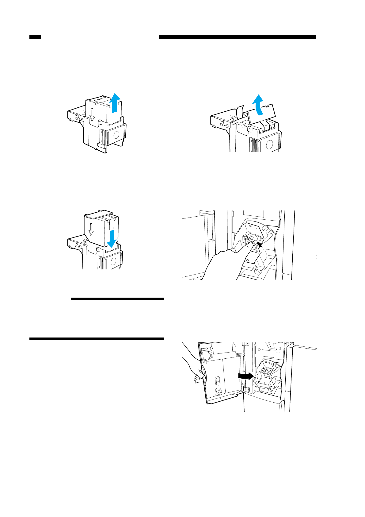
CHAPTER 1 GENERAL DESCRIPTION
4) Hold the empty staple case on its sides, and
slide it out.
Figure 1-311
5) Set a new staple case.
6) Pull the length of tape (used to hold the
staples in place) straight out.
Figure 1-313
7) Push in the stapler unit until the blue lever
returns to its original position.
Figure 1-312
Reference:
You may set no more than one staple
cartridge at a time.
Make sure that the new cartridge is one
specifically designed for the finisher unit.
Figure 1-314
8) Check to make sure that the stapler has
been locked in place, and close the front
cover.
Figure 1-315
1-16
Page 27
CHAPTER 1 GENERAL DESCRIPTION
C. Removing Staple Jams
from the Finisher Unit
If the host machine indicates the finisher
unit staple jam message, perform the following to remove the jam.
1) Remove the stack waiting to be stapled
from the delivery tray.
Figure 1-316
4) When the staple cartridge has slightly slid
out, hold and pull it out.
Figure 1-319
5) Shift down the tab on the staple cartridge.
2) Open the front cover.
Figure 1-317
3) Shift down the blue lever.
Figure 1-320
6) Remove all staples that have slid out of the
staple case.
Figure 1-321
Figure 1-318
1-17
Page 28
CHAPTER 1 GENERAL DESCRIPTION
7) Return the tab on the staple cartridge to its
original position.
8) Return the staple cartridge to its original
position, and close the front cover.
Figure 1-322
Reference
When the cover has been closed, the stapler
unit will automatically execute idle punching
several times to advance the staples.
D. Removing Paper Jams
from the Saddle Stitcher
Unit (Saddle Finisher)
If the host machine indicates the saddle
stitcher unit paper jam message, perform the
following to remove the jam.
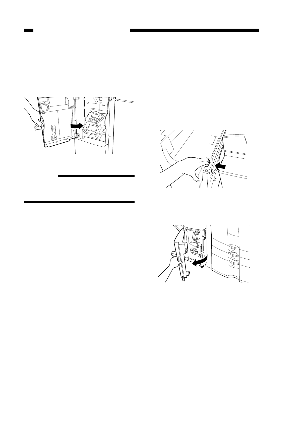
1) Holding the saddle stitcher unit as shown,
move it to detach it from the host machine.
Figure 1-323
2) Open the front lower cover.
Figure 1-324
1-18
Page 29
CHAPTER 1 GENERAL DESCRIPTION
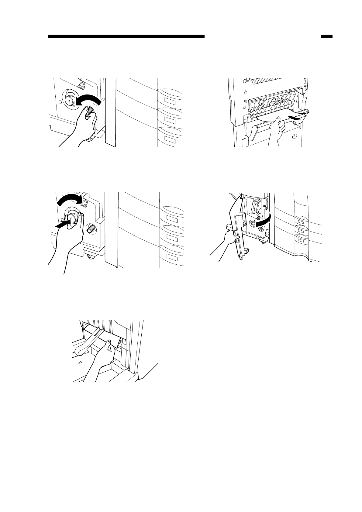
3) Turn the knob on the left side.
Figure 1-325
4) Turn the knob on the right side while pushing it in.
6) Open the inlet cover, and remov e the jam.
Figure 1-328
7) Close the front lower cover .
Figure 1-326
5) Remove the jam.
Figure 1-327
Figure 1-329
8) Connect the finisher unit.
9) Operate as instructed on the display.
1-19
Page 30
CHAPTER 1 GENERAL DESCRIPTION
E. Supplying the Saddle
Stitcher Unit with Staples
(Saddle Finisher)
If the host machine indicates the saddle
stitcher unit staple supply message, perform the
following to supply it with staples.
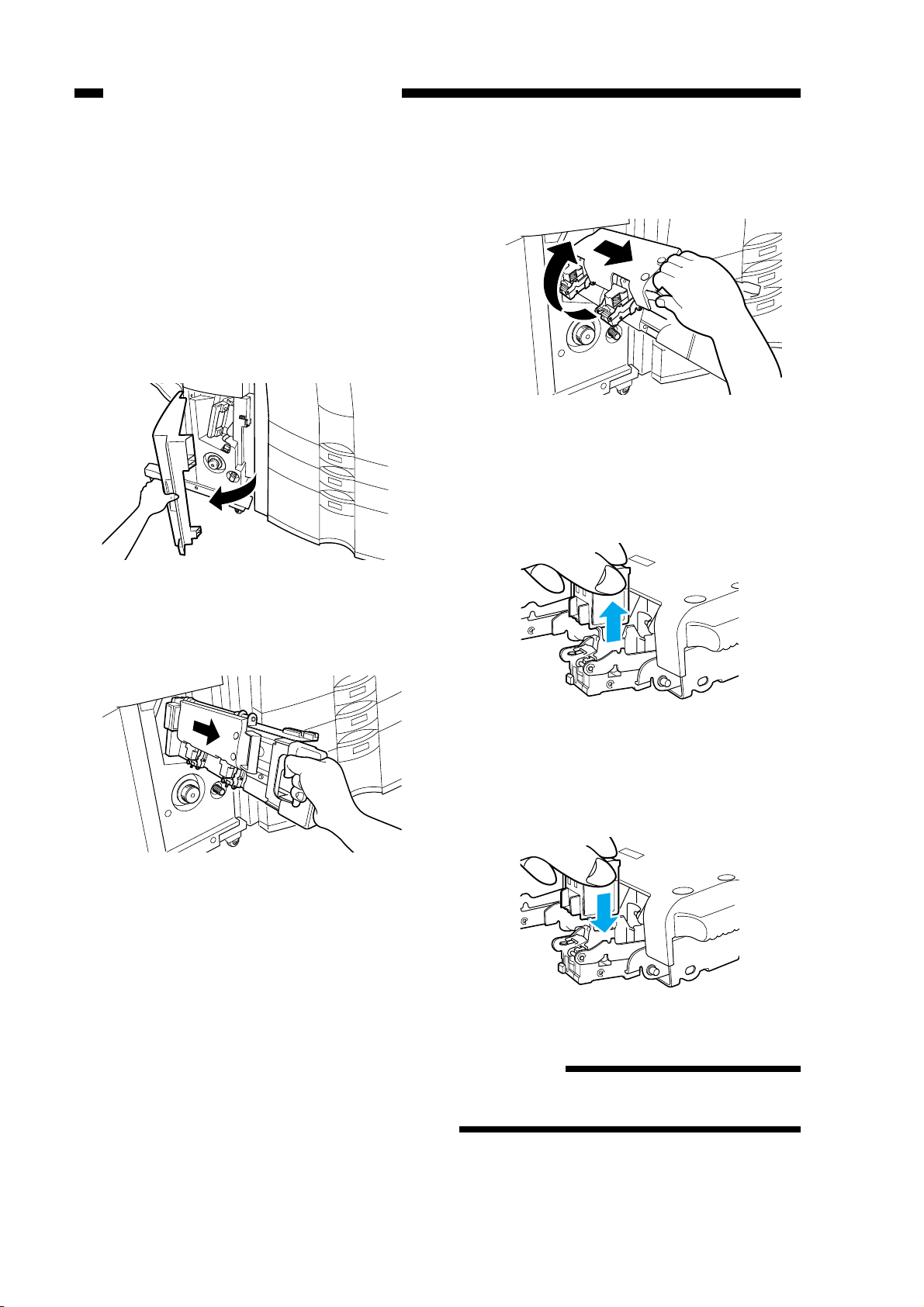
1) Open the front lower cover.
Figure 1-330
3) Pull the stitcher unit to the front once, and
then shift it up.
Figure 1-332
4) Hold the empty cartridge on its sides, and
remove it.
2) Slide out the stitcher unit.
Figure 1-331
Figure 1-333
5) Set a new cartridge.
Figure 1-334
Reference
You must always replace both cartridges at
the same time.
1-20
Page 31

CHAPTER 1 GENERAL DESCRIPTION
6) Pull the stitcher to the front once, and then
return it to its original position.
Figure 1-335
7) Push in the stitcher unit, and close the front
cover.
F. Removing Staple Jams
from the Saddle Stitcher
Unit (Saddle Finisher)
If the host machine indicates the saddle
stitcher unit staple jam message, perform the
following to remov e the jam.
1) Open the front lower cover.
Figure 1-337
Figure 1-336
2) Slide out the stitcher unit.
Figure 1-338
3) Pull the stapler of the stitcher unit to the
front once, and then shift it up.
Figure 1-339
1-21
Page 32

CHAPTER 1 GENERAL DESCRIPTION
4) Hold the cartridge on its sides, and remove
it.
Figure 1-340
5) Push down on the area identified as A, and
pull up the tab identified as B.
7) Return the cartridge to its original position.
Figure 1-343
8) Pull the stitcher of the stitcher unit to the
front once, and then return it to its original
position.
Figure 1-341
6) Remove the staple jam, and return the tab
B to its original position.
Figure 1-342
Figure 1-344
9) Push the stitcher unit back to its original
position, and close the front lower cov er.
Figure 1-345
Reference
Whenever you have removed a staple jam, be
sure to execute staple edging.
1-22
Page 33

CHAPTER 1 GENERAL DESCRIPTION
G. Removing Paper Jams
from the Puncher Unit
(option)
If the display indicates a paper jam on the
puncher unit, perform the following to remov e
the jam:
1) Open the front cover of the puncher unit.
4) Holding the finisher unit as shown, move
it to detach it from the most machine.
Figure 1-349
5) Remove any jam visible from the outside.
Figure 1-346
2) Align the triangle mark on the knob within
the range marked by .
Figure 1-347
3) Close the front cover of the puncher unit.
Figure 1-350
6) Open the upper cover, and check the inside of the finisher.
Figure 1-351
7) Lift the buffer roller cover , and remove the
jam.
Figure 1-348
Figure 1-352
1-23
Page 34
CHAPTER 1 GENERAL DESCRIPTION
8) Return the buffer roller and the b uffer roller
cover to their original position, and close
the upper cover.
Figure 1-353
9) Connect the finisher to the host machine.
Figure 1-354
10) Operate as instructed on the display.
1-24
Page 35

CHAPTER 1 GENERAL DESCRIPTION
H. Removing Punched Scrap
from the Puncher Unit
(option)
If the display indicates a punched scrap full
state on the puncher unit, perform the following to remove the punched scrap:
1) Open the front cover of the puncher unit.
Figure 1-355
2) Slide out the punched scrap container.
4) Return the punched scrap container to its
original position.
Figure 1-358
Figure 1-356
3) Discard the punched scrap.
Figure 1-357
1-25
Page 36

CHAPTER 1 GENERAL DESCRIPTION
IV. MAINTENANCE BY THE USER
A. Maintenance by the User
No.
1
2
Item
Replacing the staple cartridge (finisher unit)
Replacing the staple cartridge (saddle stitcher
unit)
When the appropriate indication is made on
the host machine’s display.
Timing
Caution:
The finisher unit and the saddle stitcher unit use different cartridge types. Be sure that the
appropriate type is used for each.
Table 1-401
1-26
Page 37

CHAPTER 2
FINISHER UNIT BASIC OPERATION
1. This chapter discusses the purpose and role of each of the finisher’s functions, and the principles of operation used for the finisher mechanical and electrical systems. It also explains the
timing at which these systems are operated.The symbol in drawings indicates transmission
of mechanical drive, and signals marked by together with the signal name indicates the
flow of electrical signals.
2. In descriptions of digital circuits on the finisher, “1” indicates a high signal voltage level, while
“0” indicates a low signal voltage level. Voltage values differ according to circuit.
A microprocessor is used on the finisher. A description of microprocessor operation is omitted
in this chapter as it is practically impossible to check internal operation of the microprocessor.
Descriptions in this chapter also assume that PCBs will not be repaired at user sites. For this
reason, descriptions of circuits on PCBs is limited to block diagrams. Two types of block diagrams are provided for separate functions: diagrams indicating details from sensors up to input
sections of major PCBs, and diagrams indicating details from the output sections of major
PCBs up the loads.
I. BASIC OPERATION ....................2-1
A. Outline .......................................2-1
B. Outline of Electrical Circuitry...... 2-2
C. Inputs to and Outputs from the
Finisher Controller PCB .............2-4
II. FEED/DRIVE SYSTEM ............. 2-10
A. Outline .....................................2-10
B. Type of Delivery Paths .............2-15
C. Feeding and Delivering ............2-18
D. Job Offset ................................ 2-21
E. Staple Operation ...................... 2-24
F. Stapler Unit .............................. 2-32
G. Tray Operation.......................... 2-38
H. Detecting the Height of
Stack on the Tray...................... 2-40
I. Shutter Operation .................... 2-42
J. Buffer Path Operation ..............2-46
K. Detecting Jams ........................2-51
III. POWER SUPPLY SYSTEM .......2-56
Page 38

I. BASIC OPERATION
A. Outline
CHAPTER 2 FINISHER UNIT BASIC OPERATION
The finisher is designed to deliver copies arriving from its host machine, and its modes of
delivery include simple stacking, job offset
(Note)
, and staple.
All operations inv olved in these modes are controlled by the finisher controller PCB, according
to the appropriate commands from the host machine.
In the case of the Saddle Finisher, copies from the host machine may be routed to the saddle
stitcher unit.
Swing guide drive system
Alignment drive system
Stapler drive system
Delivery drive system
Feeder drive system
Tray drive system
Control system
Shutter drive system
Saddle stitcher unit control system
(Saddle Finisher)
Tray drive system
Figure 2-101
Note:
The term job offset refers to shifting each sorting job, separating a single
stack into several stacks.
2-1
Page 39

CHAPTER 2 FINISHER UNIT BASIC OPERATION
B. Outline of Electrical Circuitry
The finisher’s sequence of operation is controlled by the finisher controller PCB. The finisher
controller PCB is a 16-bit microprocessor (CPU), and is used for communication with the host
machine (serial) in addition to controlling the finisher’s sequence of operations.
The finisher controller PCB responds to the various commands coming from the host machine
through a serial communications line to drive solenoids, motors, and other loads. In addition, it
communicates the finisher’s various states (information on sensors and switches) to the host machine through a serial communications circuit.
In the case of the Saddle Finisher, the f inisher controller PCB not only communicates with the
saddle stitcher controller PCB but also communicates the saddle stitcher unit’s various states (information on sensors and switches) to the host machine.
The ICs used on the finisher controller PCB are designed for the following:
●
IC1 (CPU)
Controls sequence of operations.
●
IC2 (EP-ROM)
Backs up adjustment values.
●
IC3
Contains sequence programs.
●
IC6/IC7 (RAM)
Backs up initial setting data.
●
IC4 (communications IC)
Communicates with the host machine and the saddle stitcher unit.
●
IC9 (regulator IC)
Generates PWM.
Figure 2-102 shows the flow of signals between the finisher and the options controller.
2-2
Page 40

CHAPTER 2 FINISHER UNIT BASIC OPERATION
Saddle stitcher
controller PCB
(Saddle Finisher)
Punch driver PCB
(Puncher unit (option))
Host machine
(DC controller PCB CPU)
Connecting with inserter
Saddle stitcher
controller PCB
(Saddle Finisher)
Finisher controller
PCB communication
IC1
CPU
IC2
EEP-ROM
IC4
IC
IC3
EP-ROM
IC6/IC7
RAM
IC9
Regulator IC
Finisher controller
PCB communication
IC1
CPU
Motor
Solenoid
Switch
Sensor
Motor
Solenoid
Host machine
(DC controller PCB CPU)
Punch driver PCB
(Puncher unit (option))
Inserter
driver PCB
(Inserter unit
(option)
)
Figure 2-102
IC2
EEP-ROM
IC4
IC
IC3
EP-ROM
IC6/IC7
RAM
IC9
Regulator IC
Switch
Sensor
2-3
Page 41

CHAPTER 2 FINISHER UNIT BASIC OPERATION
C. Inputs to and Outputs from the Finisher Controller PCB
1. Inputs to the Finisher Controller PCB
Finisher controller PCB
Inlet sensor
Delivery sensor
Stapling tray
sensor
Shutter open
sensor
Alignment plate
home position
sensor
Stapler shift home
position sensor
PI1
PI3
PI4
PI5
PI6
PI7
J106-3
J134-1
J122-3
J118-3
J121-3
J129-3
-7
-1
-2
-2
-3
-1
-2
-1
-2
-1
-2
-1
-2
-9
-8
-3
-2
-1
-1
-3
-2
-1
-3
-2
-4
-6
-5
-1
-3
-2
J202
J208
J207A
J205
J207A
J210
-3
-1
-2
-5
-6
-7
-11
-9
-10
-3
-1
-2
-8
-6
-7
-3
-1
-2
J17-7
J11-3
J9A-1
J12B-4
J9A-4
J12A-4
-9
-8
-2
-1
-3
-2
-6
-5
-6
-5
-6
-5
+5V
PENT
+5V
PDEL
+5V
STPTY
+5V
STOPN
+5V
JOGHP
+5V
STPHP
When the sensor detects
paper, “1”.
When the sensor detects
paper, “1”.
When the sensor detects
paper, “1”.
When the shutter opens, “1”.
When the alignment plate
is at the home position, “1”.
When the stapler is at the
home position, “1”.
Tray 1 home
position sensor
2-4
PI8
J130-3
J14A-1
-1
-2
-3
-2
+5V
TRYHP 1
When the tray 1 is at the
home position, “1”.
Figure 2-103
Page 42

CHAPTER 2 FINISHER UNIT BASIC OPERATION
2. Inputs to the Finisher Controller PCB
Finisher controller PCB
Delivery motor
clock sensor
Tray 1 paper
sensor
Tray 2 paper
sensor
Buffer path paper
sensor
Joint sensor
Door open
sensor
PI10
PI11
PI12
PI14
PI15
PI16
J120-1
J2011-3
J8011-3
J110-3
J117-3
J1130-3
-9
-2
-3
-1
-1
-3
-2
-2
-1
-1
-3
-2
-2
-1
-2
-1
-2
-1
-2
-8
-7
J2010
J8010
-1
-3
-2
-3
-1
-2
-3
-1
-2
-3
-4
-5
J207A
-1
-3
-2
-7
-9
-8
J113
J9A-9
+5V
-8
DELCLK
-7
-3
J14A-4
-1
-2
J201
J14B-7
-3
-1
-2
J801
J12A-1
-3
-1
-2
J12B-1
J24-4
+5V
-6
FSTTRAY*
-5
+5V
-9
SNDTRAY*
-8
+5V
-6
BUFPASS
-5
+5V
-3
JOINT
-2
+5V
-3
DROPN
-2
While the delivery motor
is rotating, alternately
between “0” and “1”.
When paper is present on
tray 1, “0”.
When paper is present on
tray 2, “0”.
When paper is in the
buffer path, “1”.
When the finisher is joined
with the host machine, “1”.
When the front door is
open, “0”.
Buffer path inlet
paper sensor
Swing guide
open sensor
Tray 1 lift
motor clock
sensor 1
Tray 1 lift
motor clock
sensor 2
Tray 2 lift
motor clock
sensor 1
Tray 2 lift
motor clock
sensor 2
PI17
PI18
PI9
PI19
PI23
PI24
J105-3
J127-3
J6011-3
J6011-6
J8021-3
J24-1
J11-8
-10
-12
-11
+5V
-3
BUFENTR
-2
+5V
SWGOPN
-9
+5V
SFTCLK11
+5V
-9
SFTCLK12
-8
+5V
-6
SFTCLK21
-5
+5V
-3
SFTCLK22
-2
-1
-2
-1
-1
-2
-1
-2
-4
-5
-3
-2
-4
-6
-5
J6010
-1
-3
-2
-4
-6
-1
-5
-2
J8020
-1
-6
-3
-4
-2
-5
-3
-1
-2
-6
-4
-5
-3
-1
-2
-6
-4
-5
J204
-3
-1
-2
J601
J801
J14A-10
-3
-1
-2
-6
-4
-5
-6
-4
-5
-9
-7
-8
J14A-7
J14B-4
J14B-1
-4
-6
-5
-1
-3
-2
-4
-6
-5
-1
-3
-2
When paper is present at
the buffer path inlet, “1”.
When the swing guide is
open, “1”.
When the tray 1 lift motor
is rotating, alternately
between “1” and “0”.
When the tray 1 lift motor
is rotating, alternately
between “1” and “0”.
When the tray 2 lift motor
is rotating, alternately
between “1” and “0”.
When the tray 2 lift motor
is rotating, alternately
between “1” and “0”.
Figure 2-104
2-5
Page 43

CHAPTER 2 FINISHER UNIT BASIC OPERATION
3. Inputs to the Finisher Controller PCB
PI20
Swing motor
clock sensor
PI25
Tray 2 home
position sensor
Height sensor
Door switch
N. O.
MS1
C.
J112-1
Swing guide closed detecting switch 1
N. O.
C.
MS2
PS1
J125-1
-2
-3
J135-3
-1
-2
J114-3
-2
-2
-4
-1
-2
-3
-4
J112-1
-2
-5
-4
-3
J212
-1
-2
-1
-2
J207B
-3
-2
-4
-1
-2
-3
-1
-4
J112
J209
-7
-8
-9
-1
-2
-1
-2
J14B-10
J213
J9B-5
J6-2
-3
-4
-2
-1
J5-1
J5-6
-4
-3
-12
-11
-1
-3
-4-1
-2
-7
Finisher controller PCB
+5V
SWGCLK
When the swing motor is
rotating, alternately between
“0” and “1”.
+5V
TRYHP2
+5V
Height
PWR
When the tray 2 is home
position, “1”.
Measures the distance between
the sensor and the top of the
stack on the tray.
+24V
+24VMOVE
DRSW
+24V SHIFT
When the front door
and the upper cover
are closed, “1”.
Swing guide closed detecting switch 2
N. O.
C.
MS6
Safety zone switch
J131-1
MS3
C.
N. C.
N. O.
-3
-2
Shutter closed detecting switch
MS4
N. C.
N. O.
C.
J140-3
-2
-1
J206-1
Tray coming close detection switch
J138
MS9
N. C.
N. O.
C.
-3
-1
J1151
-3
-2
-1
J1151
-4
-3
J5-8
-9
J5-3
-5
-4
J7-7
-6
-5
J5-11
-10
+24VSTPL
+24VSHIFT
TRAYSAF
SHUTCLD
TRYLMT
+24VSHIFT
SWGGCLD
When the swing
guide is closed, “1”.
When the tray is at
the delivery slot, “1”.
When the shutter is
closed, “1”.
When the tray 1 gets
close to the tray 2: "0"
J209
J206-1
-4
-3
-3
-4
-2
-3
J115
-3
-4
-2
-3
-3
J115
-2
-1
2-6
Figure 2-105
Page 44

CHAPTER 2 FINISHER UNIT BASIC OPERATION
4. Inputs to and Outputs from the Finisher Controller PCB
Staple edging
sensor
Staple home
position sensor
Cartridge switch
Staple switch
Stapler unit
Finisher controller PCB
When a staple is at the edge of
*
the stapler, “0”.
When the stapler is at the home
*
position, “0”.
*
When a cartridge is present, “0”.
When staples are present in the
*
cartridge, “0”.
*
When the stapler is connected,
“0”.
Saddle stitcher
controller PCB
Host machine
J400-9 J400-1
-8
-7
-6
-5
-4
J51-3
-4
-1
-2
-8
-9
-11
-12
-6
-7
-5
CONNECT
-2
-3
-4
-5
-6
Communication line
J2-1
Communication line
JS1
Figure 2-106
2-7
Page 45

CHAPTER 2 FINISHER UNIT BASIC OPERATION
5. Outputs from the Finisher Controller PCB
Finisher controller PCB
Flapper solenoid
SL1
Buffer inlet solenoid
SL2
Buffer outlet solenoid
SL3
Paddle solenoid
SL5
Escape solenoid
SL6
-1 -2
J107
-2
-1 -3
J108
-2
-1 -2
J109
-2
-1 -2
J128
-2
-1 -3
J123
-2
-1 -2
J701
-2 -1
-1 -11
-2 -10
J207B
-10 -2
-11 -1
J207A
J12A-7
J12B-9
-10-2
J24-7
J9B-1
J9A-10
-11-2
-8-1
-8-1
-2-1
+24V
When "0", the solenoid turns on.
FLPSL*
+24V
When "0", the solenoid turns on.
ENTSL*
+24V
When "0", the solenoid turns on.
EXITSL*
+24V
When "0", the solenoid turns on.
PDLSL*
+24V
When "0", the solenoid turns on.
ESCPSL*
Belt escape solenoid
SL7
First feed motor
M1
Delivery motor
Alignment motor
-1 -2
-2
J10-6
-1
-2
-4
-3
-5
J501
J10-6
-1
-1
-2
-4
-3
-5
-1 -2
J500
-2 -1
J12B-7
J10-1
-8
BESCPSL*
-2
-3
B*
-4
A*
-5
B
-6
A
+24V
When "0", the solenoid turns on.
+24V
According to rotation direction/speed,
changes between + and - in sequence.
According to rotation
direction/speed, changes
between + and -.
According to rotation
direction/speed, changes
between + and - in sequence.
2-8
Figure 2-107
Page 46

CHAPTER 2 FINISHER UNIT BASIC OPERATION
6. Outputs from the Finisher Controller PCB
Stapler shift motor
Staple motor
Tray 1 lift motor
J115-1
-2
-1
-2
Finisher controller PCB
According to rotation
direction/speed, changes
between + and - in sequence.
According to rotation
direction/speed, changes
between + and -.
According to rotation
direction/speed, changes
between + and -.
Tray 2 lift motor
Swing motor
Second feed motor
Inlet feed motor
According to rotation
direction/speed, changes
between + and -.
According to rotation
direction/speed, changes
between + and -.
According to rotation
direction/speed, changes
between + and -.
Figure 2-108
According to rotation
direction/speed, changes
between + and - in sequence.
2-9
Page 47

CHAPTER 2 FINISHER UNIT BASIC OPERATION
II. FEED/DRIVE SYSTEM
A. Outline
The finisher is designed to operate according to the commands from its host machine to deli ver
arriving copies to trays in the appropriate mode: simple stacking, job offset, stapling.
See Figure 2-201 for a diagram of the three modes of delivery (four for the Saddle Finisher).
Method of delivery
Normal
delivery
Saddle stitch delivery (Saddle Finisher only)
Simple stacking
Job offset
Staple
Figure 2-201
Front diagonal
Rear 1-point
Rear diagonal
2-point
Normal delivery tray
Normal delivery tray
To saddle stitcher unit
(Saddle Finisher)
Figure 2-202
2-10
Page 48

1. Normal Delivery
a. Simple Stacking
The finisher delivers copies directly to the tray.
Tray Tray
CHAPTER 2 FINISHER UNIT BASIC OPERATION
CopiesCopies
Delivery roller
Figure 2-203
Feed roller 1
Feed roller 2
2-11
Page 49
CHAPTER 2 FINISHER UNIT BASIC OPERATION
b. Job Offset
The finisher forwards all copies of each sort job to the stapling tray. The first sort job on the
stapling tray is delivered with a shift to the front of about 30 mm, and the second sort job is deli vered without being shifted. Whether the fi rst copy or the last cop y of a sort job should be shifted is
determined by the host machine.
Tray
Each sort job is stacked
alternately.
Figure 2-204
Swing guide
Stapling tray
Results of Delivering 4 Sets
Direction of delivery
Delivery roller
Figure 2-205
Figure 2-206
Stopper
Feed roller 1
Copies handled
by job offset
2-12
Page 50

CHAPTER 2 FINISHER UNIT BASIC OPERATION
c. Stapling
The finisher stacks copies arriving from its host machine on the stapling tray. Then, it staples
and delivers the copies to the appropriate tray.
Tray
Copies
Staple
Swing guide
Delivery roller
Front diagonal stapling
Rear diagonal stapling
Stapling
tray
Stopper
Figure 2-207
Rear 1-point stapling
Feed roller 1
Paper width/2
2-point stapling
Figure 2-208
2-13
Page 51

CHAPTER 2 FINISHER UNIT BASIC OPERATION
2. Saddle Stitch Delivery (Saddle Finisher)
A copy arriving in the finisher from the host machine is routed to the saddle stitcher by the
paper deflecting plate. The saddle stitcher executes stitching and saddling operations on the copy
and then delivers it to the saddle stitcher tray.
For discussions of stacks in the saddle stitcher, see Chapter 3.
To saddle stitcher
Figure 2-209
2-14
Page 52

CHAPTER 2 FINISHER UNIT BASIC OPERATION
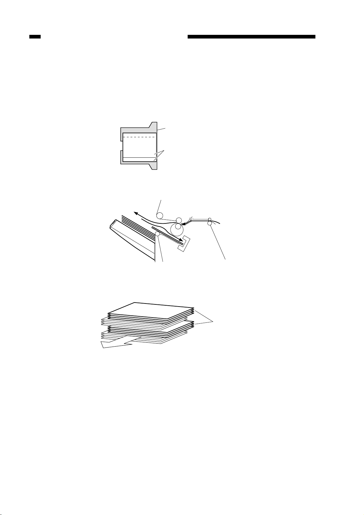
B. Type of Delivery Paths
The finisher has three different paper paths for delivery, each selected to suit paper size and
delivery mode.
1. Straight Path
When stacking copies shown in Table 2-201, the copies pass under the buffer roller.
Copy size Length or width 182 mm or less
Typical copy examples A5-R, ST-R, thick paper
Table 2-201
Delivery roller
Buffer roller
Figure 2-210
2. Buffer Paper Path 1
When stacking copies shown in Table 2-202, the copies pass over the buffer roller, increasing
the distance between copies.
Copy size Length and width 182 mm or more
Typical copy examples A3, B4, A4, A4-R, B5, B5-R, LD, LG, LT, LT-R, (excluding
transparencies and thick stock)
Table 2-202
Buffer roller
Delivery roller
Figure 2-211
Feed roller 2
2-15
Page 53

CHAPTER 2 FINISHER UNIT BASIC OPERATION
3. Buffer Paper Path 2
This is the paper path when copy sizes shown in Table 2-203 are stacked. A maximum of three
copies (three originals or more in the staple mode) are wrapped round the buffer roller, during
which job offset and stapling are performed on the stapling tray.
Copy size Length 182 to 232mm, and width 182 to 297mm
Typical copy examples A4, B5, LT, (excluding transparencies and thick stock)
Table 2-203
The following sho ws paper deli very operation in the case of three originals in the staple mode.
1) The first copy is mov ed in the direction of the buffer roller.
Buffer roller
First copy
Figure 2-212
2) The first copy wraps around the buffer roller and, at the same time, the second copy arrives
from the host machine.
First copy
Second copy
Figure 2-213
2-16
Page 54

CHAPTER 2 FINISHER UNIT BASIC OPERATION
3) The second copy is laid ov er the first copy and, at the same time, the third copy arri ves from the
host machine.
First copy
Second copy
Third copy
Figure 2-214
4) The first, second and third copies are simultaneously pulled into the stapling tray.
Second copy
Third copy
First copy
Figure 2-215
Cauiton:
The third copy as explained here is moved through buffer paper path 1. This fact is omitted from the
discussion to avoid interrupting the sequence of operations.
2-17
Page 55

CHAPTER 2 FINISHER UNIT BASIC OPERATION
C. Feeding and Delivering
1. Outline
The finisher moves copies ar ri ving from the host mac hine to the deli very tray, stapling tray, or
the saddle stitcher unit (Saddle Finisher) according to the mode of delivery. On the stapling tray, the
copies are subjected to job offset or stapling as instructed by the host machine.
The first feed motor (M1), second feed motor (M8) and inlet feed motor (M9) are stepping
motors, and delivery motor (M2) is a DC motor . These motors are controlled by the microprocessor
(CPU) on the finisher controller PCB, and rotate either clockwise or counterclockwise.
The paper paths are equipped with the following four sensors for detection of paper (arrival,
passage):
●
Inlet sensor (PI1)
●
Delivery sensor (PI3)
●
Stapling tray sensor (PI4)
●
Buffer path paper sensor (PI14)
In addition, each delivery tray is equipped with a sensor designed to detect the presence/absence of paper on it.
●
No.1 tray paper sensor (PI11)
●
No.2 tray paper sensor (PI12)
If a copy fails to reach or move past each sensor within a specific period of time, the finisher
controller PCB identifies the condition as a jam, and stops the ongoing operation, and at the same
time, informs the host machine of the condition. When all doors are closed after the paper jam is
removed, the buf fer path inlet paper sensor (PI17) checks whether or not copies are being detected
in addition to the above four sensors (inlet sensor, delivery sensor, stapling tray sensor and buffer
path paper sensor). If the sensors detect a copy, the finisher unit judges that paper jams have not
completely been removed, and sends the paper jam remov al signal to the host machine again.
2-18
Page 56

CHAPTER 2 FINISHER UNIT BASIC OPERATION
Finisher controller PCB
Swing motor drive signal
Tray 2 lift motor drive signal
Escape solenoid drive signal ESCPSL
Shift motor clock signal 1 SFTCLK 21
Shift motor clock signal 2 SFTCLK 22
Delivery motor drive signal
Alignment motor drive signal
Swing motor clock signal SWGCLK
Delivery motor clock signal DELCLK
Shift motor clock detection signal 1 SFTCLK11
PI20
PI10
Tray 1 lift motor drive signal
Paddle solenoid drive signal PDLSL
PI19
Shift motor clock detection signal 2 SFTCLK12
M5
PI9
M7
M2
Second feed motor drive signal
SL5
First feed motor drive signal
M1M8 M9
Inlet feed motor drive signal
Buffer outlet solenoid drive signal EXITSL
SL3
SL2
SL1
SL7
M6
Stapler motor drive signal
Stapler shift motor drive signal
Flapper solenoid drive signal FLPSL
Buffer inlet solenoid drive signal EXTSL
Belt escape solenoid drive signal BESCPSL
M3
PI24
PI23
M
10
Figure 2-216
M4
SL6
2-19
Page 57

CHAPTER 2 FINISHER UNIT BASIC OPERATION
Finisher controller PCB
detection signal BUFPASS
Buffer path paper
detection signal BUFENTR
Delivery detection signal PDEL
Buffer path inlet paper
No. 1 tray paper detection signal FSTTRAY
No. 2 tray paper detection signal SNDTRAY
Stapling tray paper detection signal STPTY
PI3
PI14
PI11
PI4
PI12
PI17
Inlet paper detection signal PENT
PI1
2-20
Figure 2-217
Page 58

CHAPTER 2 FINISHER UNIT BASIC OPERATION
D. Job Offset
1. Outline
In the job offset mode, sort jobs and entire copy groups are shifted to the front for delivery to
the tray, and other copies are delivered to the tray without a shift.
The copies are shifted by the alignment plate. The alignment plate is checked by the alignment
plate home position sensor (PI6) to find out whether it is at the home position.
The finisher controller PCB drives the alignment motor (M3) at power-on to return the align-
ment plate to its home position.
The finisher controller PCB stops the delivery motor (M2) when the trailing edge of the copy
has moved past the feed roller 2. Then, the f inisher controller PCB rotates the deliv ery motor counterclockwise, and drives the swing motor (M7). As a result, the drive of the delivery motor is transmitted to the swing guide to move up the guide. When the swing guide open sensor (PI18) detects
the swing guide, the delivery motor stops, and the swing guide is held at the up position.
When the swing guide has moved up, the feed belts attached to the feed roller 2 mov e the copy
to the stapling tray. The presence of paper on the stapling tray is monitored by the stapling tray
sensor (PI4). (The first sheet is fed to the stapling tray while the swing guide is moving up.)
The finisher controller PCB drives the alignment motor (M3) in advance, and keeps the alignment plate in wait at a point 10 mm behind the trailing edge of a sheet. Whenever one sheet is
moved to the stapling tray, each sheet is aligned, and when the fifth or last sheet in a sort job/group
is fed to the stapling tray, the escape solenoid (SL6) moves the guide plate away and under the
stapling tray. From then on, the alignment motor shifts the sheets to the front by 30 mm.
When the copy has been shifted, the finisher controller PCB rotates the alignment motor counterclockwise to move the alignment plate to a point 10 mm behind the trailing edge of the sheet.
This alignment operation is repeated until alignment of the fifth or last sheet in a sort job is completed. At this time, the swing guide is moved down and is closed, and the delivery motor rotates
clockwise to deliver the sheet.
2-21
Page 59

CHAPTER 2 FINISHER UNIT BASIC OPERATION
Guide plate
Alignment plate
Alignment plate
home position sensor (PI6)
Escape solenoid
(SL6)
Sequence of Operation (job offset)
Inlet sensor (PI1)
Delivery sensor (PI3)
Inlet feed motor (M9)
First feed motor (M1)
Second feed motor (M8)
Delivery motor (M2)
Paper
Alignment motor (M3)
Figure 2-218
Start signal
Host machine delivery signal
2-22
Staple tray sensor (PI4)
Alignment motor (M3)
Alignment plate home
position sensor (PI6)
Swing motor (M7)
Swing guide open
sensor (PI18)
Swing guide closed
detecting switch 1 (MS2)
Escape solenoid (SL6)
: Motor CW rotation : Motor CCW rotation
Figure 2-219
Page 60

CHAPTER 2 FINISHER UNIT BASIC OPERATION
2. Flow of Job Offset Operations
1) The swing guide moves up and, at the same time, the feed belts move the sheet to the stapling
tray.
Swing guide
Offset sheet
Feed roller 2
Knurled belts
Tray 1/2
Delivery
roller
Stapling tray
Stopper
Figure 2-220
2) The alignment plate shifts the sheet to the front.
Existing stack
Alignment plate
Offset sheet
Figure 2-221
3) The swing guide moves down and, at the same time, the delivery roller delivers the sheet.
Offset sheet
Swing guide
Tray 1/2
Feed roller 2
Knurled belts
Delivery
roller
Stapling tray
Stopper
Figure 2-222
2-23
Page 61

CHAPTER 2 FINISHER UNIT BASIC OPERATION
E. Staple Operation
1. Outline
The stapler unit staples a stack of as many sheets as specified.
The stapling position differs according to the selected staple mode and paper size.
The stapler unit is checked by the stapler shift home position sensor (PI7) to find out whether it
is at the home position.
When starting operation after power-on, the finisher controller PCB drives the stapler shift
motor (M4) to return the stapler unit to the home position. If the stapler is already at the home
position, it is kept as it is in wait.
Stapler shift
motor (M4)
Sheets
Stapler shift home
position sensor (PI7)
Stapler
Figure 2-223
2-24
Page 62

CHAPTER 2 FINISHER UNIT BASIC OPERATION
Paper width/2
Front diagonal stapling
Rear diagonal stapling
2-point stapling
Rear 1-point stapling
Figure 2-224
2-25
Page 63

CHAPTER 2 FINISHER UNIT BASIC OPERATION
2. First Sheet
The finisher controller PCB stops the delivery motor (M2) as soon as the trailing edge of the
first sheet has moved past the feed roller 2. Then, it rotates the delivery motor clockwise to switch
the gear drive to the swing motor (M7), causing the swing guide to mo ve up. When the swing guide
open sensor (PI18) finds the swing guide at the up position, the swing motor stops, maintaining the
swing guide at the up position.
When the swing guide has moved up, the knurled belts of the feed roller 2 mov e the sheet to the
stapling tray. (The first sheet is fed to the stapling tray while the swing guide is moving up.) The
presence of paper on the stapling tray is detected by the stapling tray sensor (PI4).
The finisher controller PCB drives the alignment motor (M3) when the stapling tray paper
sensor has detected paper to put sheets in order . The alignment plate is k ept in w ait in adv ance at a
point 10 mm behind the trailing edge of the paper.
The swing guide is kept in wait at the up position until the last sheet is output onto the stapling
tray.
Swing guide
First sheet
Tray 1/2
Feed roller 2
Knurled belts
Delivery roller
Stapling tray
Stapler
Figure 2-225
2-26
Page 64

Swing guide
Swing guide open
sensor (PI18)
CHAPTER 2 FINISHER UNIT BASIC OPERATION
Swing guide closed
detecting switch 1,2
(MS2/MS6)
Delivery roller
Swing motor
clock sensor
(PI20)
Delivery motor
clock sensor
(PI10)
Swing motor (M7)
Delivery motor (M2)
Figure 2-226
2-27
Page 65

CHAPTER 2 FINISHER UNIT BASIC OPERATION
3. Second and Subsequent Sheets
The finisher controller PCB turns on the belt escape solenoid (SL7) before the trailing edge of
the second and subsequent sheets have mov ed past the feed roller 2 to make the knurled belt escape.
This operation is performed to reduce the time it takes for the trailing edge of the paper to fall on the
stapling tray, and to improve the product duty. The finisher controller PCB turns on the paddle
solenoid (SL5) as soon as the trailing edge of the second and subsequent sheets have mov ed past the
feed roller 2, causing the drive of the second feed motor (M8) to rotate the paddle. The sheets are
pushed by the paddle and moved to the stapling tray. Almost simultaneously with the trailing edge
of the sheet falling into the stapling tray , the belt escape solenoid turns off to return the knurled belts
that were in the escape position to its original position, and feed the sheet onto the stapling tray.
When the sheet has been output onto the stapling tray , the finisher controller PCB rotates the alignment motor (M3) to put the sheets in order.
Swing guide
Second and
subsequent
sheets
Paddles
Feed roller 2
Tray 1/2
Delivery
roller
Stapling tray
Figure 2-227
Knurled belts
SL7
Belt escape solenoid
Stapler
2-28
Page 66

Knurled belts
CHAPTER 2 FINISHER UNIT BASIC OPERATION
Escape direction
Belt escape
solenoid (SL7)
Figure 2-228
Paddles
Paddle
solenoid (SL5)
Paddles
Second and
subsequent sheets
First sheet
Stapler
M8
Second feed motor
Stopper
Figure 2-229
2-29
Page 67

CHAPTER 2 FINISHER UNIT BASIC OPERATION
4. Last Sheet
When the last sheet has been put in order, the finisher controller PCB turns on the alignment
motor (M3) to move the alignment plate to the alignment position (to butt the plate against the
stack). Then, the finisher controller PCB rotates the swing motor (M7) counterclockwise to move
down the swing guide.
The finisher controller PCB moves the stapler according to the staple mode for stapling.
From then on, it rotates the delivery motor (M2) clockwise to deliver the stack to the tray.
Swing guide
Sheets
Feed roller 2
Knurled belts
Tray 1/2
Delivery
roller
Stapling tray
Stapler
Figure 2-230
2-30
Page 68

Swing guide
CHAPTER 2 FINISHER UNIT BASIC OPERATION
Delivery roller
Swing motor (M7)
Delivery motor (M2)
Figure 2-231
2-31
Page 69

CHAPTER 2 FINISHER UNIT BASIC OPERATION
F. Stapler Unit
Stapling is executed by the staple motor (M6). A single rotation of the cam by the motor results
in one stapling operation.
The cam is checked by the staple home position sensor (PI22) to find out whether it is at the
home position.
The stapler motor is controlled by the microprocessor (IC1) on the finisher controller so that it
is rotated clockwise or counterclockwise.
When the stapling home position sensor is off, the finisher controller PCB rotates the stapler
motor clockwise until the sensor turns on so as to return the stapling cam to its initial state.
The presence/absence of the staple cartridge is detected by the staple switch (MS8). The presence/absence of staples inside the staple cartridge is detected by the staple detecting switch (MS9).
The staple edge sensor (PI21) is used to find out whether a staple has been edged out to the end of
the cartridge.
The finisher controller PCB does not driv e the staple motor (M6) unless the swing guide closed
detecting switch 2 (MS6) is on (i.e., the swing guide is closed). This is to protect against injuries
that could occur when a finger is stuck inside the stapler.
2-32
Page 70

CHAPTER 2 FINISHER UNIT BASIC OPERATION
Figure 2-232
M6
Staple motor drive
signal
Staple edge detection signal
Finisher controller PCB
Stapling home
position detection signal
Figure 2-233
Cartridge detection signal
Staple detection signal
2-33
Page 71

CHAPTER 2 FINISHER UNIT BASIC OPERATION
Start signal
Host machine delivery signal
Inlet sensor (PI1)
Delivery sensor (PI3)
Inlet feed motor (M9)
First feed motor (M1)
Second feed motor (M8)
Delivery motor (M2)
Stapling tray sensor (PI4)
Alignment motor (M3)
Alignment guide home
position sensor (PI6)
Swing guide open
sensor (PI18)
Swing guide closed
detecting switch 1 (MS2)
Paddle solenoid (SL5)
Belt escape solenoid
(SL7)
Staple motor (M6)
First sheet
Stacking
Second sheet
Stapling
Delivery
Staple home position
sensor (PI22)
Stapler shift motor (M4)
: Motor CW rotation : Motor CCW rotation
Figure 2-234
2-34
Page 72

CHAPTER 2 FINISHER UNIT BASIC OPERATION
5. Shifting the Stapler Unit
The stapler unit is moved by the stapler shift motor (M4). Its home position is detected by the
stapler shift home position sensor (PI7). When the start signal arrives from the host machine, the
stapler moves to the center of its mov ement range. This mov ement occurs regardless of the selected
mode of delivery, as no specific mode is recognized at this point in time. When the command for
stapling arrives from the host machine after the f irst sheet has reached the host machine pre-registration sensor, the stapler mo v es to the staple w ait position to suit the appropriate stapling position
and paper size.
See Figures 2-235 and later for an idea of the wait position according to the stapling mode.
a. Front Diagonal Stapling
The position is the same as the stapling position.
Stapling tray delivery
direction
Stopper
Stopper
Guide plate
Stapler
Figure 2-235
2-35
Page 73

CHAPTER 2 FINISHER UNIT BASIC OPERATION
b. Rear 1-Point Stapling
The stapler is kept in wait at the center position. The stapler is mov ed to and from the stapling
position for each stapling operation.
Stopper
Stapling position
Wait position
Stapling tray delivery
direction
Stopper
Stapler
Guide plate
Figure 2-236
c. Rear Diagonal Stapling
For A4, LT and B5 sizes, the stapler is kept in wait toward the rear away from the stapling
position. The stapler is moved to and from the stapling position for each stapling operation.
Stapler
Wait position
Stapling position
Stopper
Stapling tray delivery
direction
2-36
Stopper
Guide plate
Figure 2-237
Page 74

CHAPTER 2 FINISHER UNIT BASIC OPERATION
d. 2-Point Stapling
The stapler is kept in wait at the center of the paper. Stapling occurs at two points, first at the
rear and then at the front.
Stopper
Stapling position
Wait position
Stapler
Stapling tray delivery
direction
Stapling position
Guide plate
Figure 2-238
Stopper
2-37
Page 75

CHAPTER 2 FINISHER UNIT BASIC OPERATION
G. Tray Operation
The finisher has two delivery trays-upper tray 1 and lower tray 2. The upper and lower trays
move up and down independently.
Tray 1 is moved up and down by the tray 1 lift motor (M5), and tray 2 by the tray 2 lift motor
(M10).
The tray 1 position is detected by counting the clock pulses of tray 1 lift motor clock sensors 1
and 2 (PI9 and PI19) in relation to the tray 1 home position sensor (P18). The tray 2 position is
detected by counting the clock pulses of tray 2 lift motor clock sensors 1 and 2 (PI23 and PI24) in
relation to the tray 2 home position sensor (PI25).
When the tray is already at the home position, it is moved aw ay fr om the home position once,
then returned to that position.
When both tray 1 and tray 2 are at the home position, the above operation is performed for tray
1 and tray 2 in this order.
The finisher controller PCB moves up and do wn the tray selected by the host machine so that it
is positioned at the delivery slot.
The upper limit of the tray is detected by the tray coming close detecting switch (MS9). The
finisher controller PCB stops the drive (up) of the tray 1 lift motor (M5) as soon as the tray upper
limit detecting switch turns on.
The height of the stack on the tray is identified by the height sensor (PS1), which measures its
distance from the top of the stack. The tray is moved do wn when the distance between the top of the
stack and the delivery assembly drops to a specif ic measurement.
The finisher controller PCB cuts off the +24V po wer of the tray 1 lift motor (M5) as soon as the
safety zone switch (MS3) turns on while the shutter and the swing guide are open, stopping the
operation of the finisher.
2-38
Page 76

Tray 1 lift
motor
One way
gear
CHAPTER 2 FINISHER UNIT BASIC OPERATION
Tray 1 lift
motor clock
sensor / and 2
Tray coming close
detection switch
Rack
Tray 2 lift
motor
One way
gear
Tray 2 lift motor
clock sensor / and 2
Figure 2-239
2-39
Page 77

CHAPTER 2 FINISHER UNIT BASIC OPERATION
H. Detecting the Height of Stack on the Tray
1. Outline
The number of sheets delivered to the tray and the number of sets (number of stapling operations) are stored in memory by the finisher controller PCB. The height of the stack is check ed by the
height sensor (PS1). See Table 2-204 for the maximum loading capacity of each tray.
The finisher controller PCB stops operation when the conditions in Table 2-204 occur, informing the host machine that the tray is full.
Non-staple sort Staple sort
Stacking
mode
Small-size
Large-size
Mixed sizes
Small-size
Large-size
Mixed sizes
Height
Notes: 1. The capacity for the non-staple sort mode is approximate and computed based on 80 g/m2 paper.
2. Alignment for stacks containing 750 sheets or more is not guaranteed.
3. Stacking height precision is ±7 mm.
250 mm high
(2000 sheets)
140 mm high
(1000 sheets)
74 mm high
(500 sheets)
110 mm high
(750 sheets/
50 sets)
74 mm high
(500 sheets/
50 sets)
22 mm high
(500 sheets/
50 sets)
Table 2-204
Caution:
1. The term “small-size” stands for A4, LT, and B5.
2. The term “large-size” stands for A3, A4-R, B4, LG, LD, LT-R, FOLIO and COMUTER.
2-40
Page 78

CHAPTER 2 FINISHER UNIT BASIC OPERATION
Height sensor (PS1)
Paper
Figure 2-240
2-41
Page 79

CHAPTER 2 FINISHER UNIT BASIC OPERATION
I. Shutter Operation
When the tray 1 passes the delivery slot, the f inisher controller PCB closes the shutter mounted
on the delivery slot before moving the tray, preventing the existing stack on the tray by the deli v ery
slot and intrusion of the hands.
The shutter moves up (to close) when the second feed motor (M8) rotates counterclockwise,
and is held in position when the motor stops. When the second feed motor rotates counterclockwise
once again, it moves down (to open) to enable delivery.
When the shutter is held at the up position, claws slide out of the swing guide to engage the
back of the shutter . This way , the existing slack and the s wing guide engage while the tray is moved,
preventing the guide from opening. The claws slide in when the shutter is moved down to release
the engagement.
The upward movement of the shutter is monitored by the shutter closed detecting switch (MS4),
and the downward movement is monitored by the shutter open sensor (PI5).
See the following diagrams for how these operations take place.
1) The second feed motor rotates counterclockwise to move the shutter up.
2-42
M8
Second feed motor
Figure 2-241
Page 80

CHAPTER 2 FINISHER UNIT BASIC OPERATION
2) The tray 1,2 lift motor rotates, and the new tray moves to the stacking lower limit. The distance
of movement is detected by1 the tray 1 lift motor clock sensor 1/2 (PI9/19) or tray 2 lift motor
clock sensor 1/2 (PI22/PI24).
Tray 1 lift motor
Tray 2 lift motor
M5
M10
Figure 2-242
3) The second feed motor rotates counterclockwise, and the shutter moves do wn.
M8
Second feed motor
Figure 2-243
2-43
Page 81

CHAPTER 2 FINISHER UNIT BASIC OPERATION
4) The tray lift motor rotates, and the tray moves to suit the height of the stack. The appropriate
height in relation to the existing stack is checked by the height sensor (PS1).
Height sensor (PS1)
M10
Tray 2 lift motor
Shutter closed
detecting
switch (MS4)
Shutter open
sensor (PI5)
Figure 2-244
Claw
Shutter
Claw
2-44
Figure 2-245
M8
Second feed motor
One-way cam
Page 82

Second feed motor (M8)
Tray 1 lift motor (M5)
Tray 2 lift motor (M10)
Shutter closed detecting
switch (MS4)
Shutter open
sensor (PI5)
CHAPTER 2 FINISHER UNIT BASIC OPERATION
Sequence Operations (shutter drive)
Move from Tray 1 to Tray 2
Tray moved
Shutter
closed
Shutter
opened
Height sensor (PS1)
Correct height detected
Motor CW rotation Motor CCW rotation
Figure 2-246
2-45
Page 83

CHAPTER 2 FINISHER UNIT BASIC OPERATION
J. Buffer Path Operation
1. Outline
This machine is provided with a buffer paper path for continuously receiving paper from the
host machine during stapling and job offset operation on the stapling tray. A maximum of three
copies (three originals or more in the staple mode) are wrapped around the buf fer roller . During this
time, job offset and stapling are performed on the stapling tray.
The following sho ws operation on the buffer paper path.
1) When the first sheet arrives, the buffer inlet solenoid (SL2) remains off. The first sheet enters
the buffer path.
OFF
SL2
First sheet
Buffer inlet solenoid
Figure 2-247
2) When the leading edge of the sheet has moved past the buf fer path inlet paper sensor (PI17), the
buff er outlet solenoid (SL3) turns on so as to cause the sheet to wrap around the buffer roller.
Buffer outlet
solenoid
ON
SL3
Buffer path inlet paper
sensor (PI17)
2-46
Figure 2-248
Page 84

CHAPTER 2 FINISHER UNIT BASIC OPERATION
3) When the leading edge of the sheet has moved past the buffer path paper sensor (PI14), the buffer
roller stops and waits for the second sheet.
First sheet
Second sheet
Buffer path paper
sensor (PI14)
Figure 2-249
4) W hen the second sheet arrives and its leading edge reaches the inlet sensor (PI1), the buffer
roller starts to operate once again.
First sheet
Second sheet
Inlet sensor (PI1)
Figure 2-250
2-47
Page 85
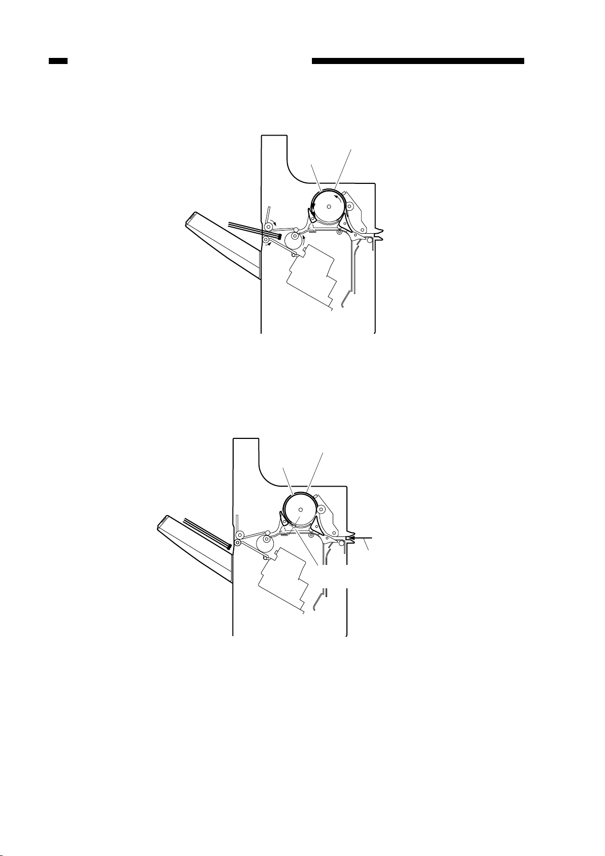
CHAPTER 2 FINISHER UNIT BASIC OPERATION
5) The buffer roller continues to rotate, and the second sheet overlaps the first sheet.
Second sheet
First sheet
Figure 2-251
6) When the trailing edge of the second sheet has moved past the b uf fer path paper sensor (PI14),
the buff er roller stops and waits for the third sheet.
Second sheet
First sheet
Third sheet
Buffer path paper
sensor (PI14)
2-48
Figure 2-252
Page 86

CHAPTER 2 FINISHER UNIT BASIC OPERATION
7) When the third sheet arrives and its leading edge reaches the inlet sensor (PI1), the buffer roller
starts to operate once again.
Second sheet
First sheet
Third sheet
Inlet sensor (PI1)
Figure 2-253
8) W hen the leading edge of the third sheet reaches the inlet sensor (PI1), the buffer outlet solenoid (SL3) turns off so that the path is directed in the direction of deliv ery. (The actual switchover will occur after the trailing edge of the first sheet has moved past the flapper.)
Second sheet
Buffer outlet
solenoid
SL3
OFF
First sheet
Third sheet
Inlet sensor (PI1)
Figure 2-254
2-49
Page 87

CHAPTER 2 FINISHER UNIT BASIC OPERATION
9) The buffer roller continues to rotate, the third sheet overlaps the first and second sheets, and the
three sheets are fed together towards the delivery roller.
Figure 2-255
2-50
Page 88

CHAPTER 2 FINISHER UNIT BASIC OPERATION
K. Detecting Jams
The following sensors are used to detect the presence/absence of paper and to make sure that
sheets are moved properly:
●
Inlet sensor (PI1)
●
Delivery sensor (PI3)
●
Stapling tray sensor (PI4)
●
Buffer path paper sensor (PI14)
A jam is identified with reference to the presence/absence of paper at each specific sensor at the
times programmed in the memory of the microprocessor (CPU) on the finisher controller PCB.
When the CPU identifies a jam, it suspends the finisher’s delivery operation and informs the
host machine DC controller of the presence of a jam. After the paper jam is removed, the buf fer path
inlet paper sensor (PI17) checks whether or not copies are being detected in addition to the above
four sensors (inlet sensor, deli v ery sensor, stapling tray sensor and buffer path paper sensor). If the
sensors detect a copy when all doors are closed, the finisher unit judges that paper jams have not
completely been removed, and sends the paper jam remov al signal to the host machine again.
The tray 1 paper sensor (PI11) and tray 2 paper sensor (PI12) are not used to detect jams.
PI3
PI14
PI1
PI4
No. Sensor names
PI1 Inlet sensor
PI3 Delivery sensor
PI4 Stapling tray sensor
PI14 Buffer path paper sensor
Figure 2-256 Table 2-205
2-51
Page 89

CHAPTER 2 FINISHER UNIT BASIC OPERATION
1. Inlet Sensor Delay Jam
The inlet sensor does not detect paper when feeding an equivalent of 400 mm from when the
host machine delivery signal has been issued.
Host machine delivery signal Host machine delivery signal
Jam check
Inlet sensor (PI1)
Inlet feed motor (M9)
Equivalent of 400 mm
Normal
Jam check
Inlet sensor (PI1)
Inlet feed motor (M9)
Equivalent of 400 mm
Jam
Figure 2-257
2. Inlet Sensor Stationary Jam
The sheet does not move past the inlet sensor when an equi valent of twice the feeding length of
the sheet has been fed after the sensor turned on.
Equivalent of size x 2
Jam
Jam check
Inlet sensor (PI1)
Inlet feed motor (M9)
Equivalent of size x 2
Normal
Jam check
Inlet sensor (PI1)
Inlet feed motor (M9)
Figure 2-258
3. Buffer Path Paper Sensor Delay Jam
The buffer inlet sensor does not detect paper when an equi v alent of 550 mm has been fed after
the inlet sensor turned on.
Equivalent of 550 mmEquivalent of 550 mm
Jam check
Inlet sensor (PI1)
Buffer path paper
sensor (PI14)
First feed motor (M1)
Normal
Jam check
Inlet sensor (PI1)
Buffer path paper
sensor (PI14)
First feed motor (M1)
Jam
Figure 2-259
2-52
Page 90

CHAPTER 2 FINISHER UNIT BASIC OPERATION
Jam check
Equivalent of size x 2
Buffer path paper
sensor (PI14)
Normal
First feed motor (M1)
Jam check
Equivalent of size x 2
Buffer path paper
sensor (PI14)
Jam
First feed motor (M1)
4. Buffer Path Paper Sensor Stationary Jam
The sheet does not move past the buffer inlet sensor when an equivalent of twice the feeding
length of the sheet has been fed after the sensor turned on.
Figure 2-260
5. Delivery Sensor Delay Jam
a. Straight Path
The delivery sensor does not detect paper when an equi v alent of 476 mm has been fed after the
inlet sensor turned on.
Jam check
Inlet sensor (PI1)
Delivery sensor (PI3)
First feed motor (M1)
Second feed motor
(M8)
Equivalent of 476 mm
Normal
Figure 2-261
Jam check
Inlet sensor (PI1)
Delivery sensor (PI3)
First feed motor (M1)
Second feed motor
(M8)
Equivalent of 476 mm
Jam
2-53
Page 91

CHAPTER 2 FINISHER UNIT BASIC OPERATION
b. Buffer Path
The delivery sensor does not detect paper when an equi v alent of 772 mm has been fed after the
inlet sensor turned on.
Equivalent of 772 mm Equivalent of 772 mm
Jam check
Jam check
Inlet sensor (PI1)
Delivery sensor (PI3)
First feed motor (M1)
Second feed motor
(M8)
Normal
Inlet sensor (PI1)
Delivery sensor (PI3)
First feed motor (M1)
Second feed motor
(M8)
Figure 2-262
6. Delivery Sensor Stationary Jam
The sheet does not move past the delivery sensor when an equivalent of twice the feeding
length of the sheet has been fed after the delivery sensor turned on.
Equivalent of size x 2 Equivalent of size x 2
Jam check
Delivery sensor (PI3)
Second feed motor
(M8)
Normal
Jam check
Delivery sensor (PI3)
Second feed motor
(M8)
Jam
Jam
Delivery motor (M2)
Delivery motor (M2)
Figure 2-263
2-54
Page 92

CHAPTER 2 FINISHER UNIT BASIC OPERATION
7. Stapling Tray Sensor Stationary Jam
The sheet does not move past the stapling tray sensor 1 sec after the deli very motor (M2) turned
on.
1 sec 1 sec
Jam check
Stapling tray
sensor (PI4)
Delivery motor (M2)
Normal
Jam check
Stapling tray
sensor (PI4)
Delivery motor (M2)
Jam
Figure 2-264
8. Timing Jam
The inlet sensor (PI1) detects a sheet before the delivery signal is received from the host machine.
9. Staple Jam
When the staple motor (M6) is rotating clockwise, the staple home position sensor (PI22) does
not turn on within 0.5 sec. after it has turned off. However, the sensor turns on within 0.5 sec. after
the motor has been rotated counterclockwise.
10. Power-On Jam
One of the inlet sensor (PI1), delivery sensor (PI3), b uffer path paper sensor (PI4) or buf fer path
inlet paper sensor (PI17) detects paper at power-on.
11. Door Open Jam
One of the joint sensor (PI15), door open sensor (PI16) or door switches (MS1) detects the
cover open during operation (including front door switch (MS2P) when the optional puncher unit is
mounted).
12. Punch Jam
The punch home sensor (PI3P) does not turn on again within 200 msec after turning off.
13. Stay Jam Caused By Finisher Start Signal OFF
The finisher start signal is turned OFF in the host machine while paper is being fed in the
finisher.
2-55
Page 93

CHAPTER 2 FINISHER UNIT BASIC OPERATION
III. POWER SUPPLY SYSTEM
1. Outline
The finisher controller PCB is supplied with 24 VDC po wer (and 5 VDC power) when the host
machine is turned on. 24 VDC one is used to drive the motor solenoids, while 5 VDC is used for
sensors and ICs on PCBs. Both lines are also used to feed power from the finisher controller PCB
to the saddle stitcher controller PCB. Power is also supplied to the punch driver PCB when the
optional puncher unit is mounted.
Some of the 24 VDC power used to driv e motors is cut off when the door switch (MS1) is open.
The power to the saddle stitcher controller PCB, however, will not be cut off.
Figure 2-301 is a block diagram showing the power supply system.
Host
machine
J1-1
J2-6
Saddle stitcher
controller PCB
(Saddle Finisher)
Circuit breaker
(CB1)
Finisher controller PCB
Door switch
(MS1)
Motor
Motor
Solenoid
Sensors
Logic
Punch driver PCB
(Puncher Unit (option))
Figure 2-301
2. Protection Functions
The 24 VDC power line used to drive motors and solenoids is equipped with a circuit breaker
(CB1) for protection against overcurrent. The 24 V line used to drive the first feed motor (M1),
alignment motor (M3), and stapler shift motor (M4) are equipped with a fuse, which is designed to
blow when an ov ercurrent occurs.
2-56
Page 94

CHAPTER 3
SADDLE STITCHER UNIT
BASIC OPERATION
1. This chapter discusses the purpose and role of each of the stitcher’s functions, and the principles of operation used for the stitcher mechanical and electrical systems. It also explains the
timing at which these systems are operated.
The symbol in drawings indicates transmission of mechanical drive, and signals marked
by together with the signal name indicates the flow of electrical signals.
2. In descriptions of digital circuits on the stitcher, “1” indicates a high signal voltage level, while
“0” indicates a low signal voltage level. Voltage values differ according to circuit.
A microprocessor is used on the stitcher. A description of microprocessor operation is omitted
in this chapter as it is practically impossible to check internal operation of the microprocessor.
Descriptions in this chapter also assume that PCBs will not be repaired at user sites. For this
reason, descriptions of circuits on PCBs is limited to block diagrams. Two types of block diagrams are provided for separate functions: diagrams indicating details from sensors up to input
sections of major PCBs, and diagrams indicating details from the output sections of major
PCBs up the loads.
I. BASIC OPERATION ....................3-1
A. Outline .......................................3-1
B. Electrical Circuitry ...................... 3-2
C. Inputs to and Outputs from the
Saddle Stitcher Controller
PCB ........................................... 3-3
II. FEEDING/DRIVE SYSTEM ......... 3-8
A. Outline .......................................3-8
III. PAPER OUTPUT
MECHANISM............................. 3-14
A. Outline .....................................3-14
B. Controlling the Inlet
Flappers ...................................3-17
C. Controlling the Movement of
Sheets...................................... 3-21
D. Aligning the Sheets .................. 3-23
E. Controlling the Phase of the
Crescent Roller ........................3-26
IV. STITCHING SYSTEM ............... 3-28
V. FOLDING/DELIVERY
SYSTEM ....................................3-31
VI. CHECKING FOR A JAM ........... 3-38
VII. POWER SUPPLY ...................... 3-43
Page 95

CHAPTER 3 SADDLE STITCHER UNIT BASIC OPERATION
I. BASIC OPERATION
A. Outline
The unit “stitches” (2 points) a stack of sheets delivered by the f inisher unit and folds it in two
for delivery. All these operations are controlled by the saddle stitcher controller PCB in response to
commands from the host machine via the finisher unit.
Finisher unit control system
Guide plate drive system
Control system
Paper positioning plate
drive system
Alignment drive system
Stitcher drive system
Delivery drive system
Feed drive system
Paper pushing plate
drive system
Paper folding roller
drive system
Figure 3-101
3-1
Page 96

CHAPTER 3 SADDLE STITCHER UNIT BASIC OPERATION
B. Electrical Circuitry
The sequence of operations used for the saddle stitcher is controlled by the saddle stitcher
controller PCB. The saddle stitcher controller PCB has a microprocessor. This microprocessor is
used to control the sequence of operations and to handle serial communications with the finisher
controller PCB, driving solenoids and motors in response to the various commands from the finisher controller PCB.
The saddle stitcher controller PCB is also used to communicate the state of various sensors and
switches to the finisher controller PCB in serial.
The functions of the major ICs mounted on the saddle stitcher controller PCB are as follows:
●
Q1
Controls the sequence of operations.
●
Q2
Contains the sequence program.
●
Q3
Controls the sequence of operations.
●
Q4
Handles IPC communications.
Electrical circuitry block diagram
Sensors
Switches
Saddle stitcher
controller PCB
Q1 CPU
Q2
ROM
Q3
RAM
Q4
Communi-
cations IC
Finisher controller
PCB
Figure 3-102
Motors
Solenoids
Host machine
3-2
Page 97

CHAPTER 3 SADDLE STITCHER UNIT BASIC OPERATION
C. Inputs to and Outputs from the Saddle Stitcher Controller PCB
1. Inputs to the Saddle Stitcher Controller PCB
Saddle stitcher controller PCB
Paper pushing
plate motor
clock sensor
Front door
open/closed
sensor
Delivery cover
sensor
Paper folding
motor clock
sensor
Alignment
plate home
position sensor
Tray paper
sensor
PI1S
PI2S
PI3S
PI4S
PI5S
PI6S
J107-1
J104-3
J103-3
J102-1
J101-3
J100-3
J11-15
-2
-3
-14
-13
+5V
LUNGECLK
When the paper pushing plate
motor is rotating, alternately
between “1” and “0”.
J11-10
-1
-2
J303-1
-1
-2
-2
-3
-1
-2
-1
-1
-3
-2
-2
J309-1
J502
J402A
-3
-2
-3
-2
J402
-3
-1
-2
J203-3
J209-3
-4
-6
-5
J11-7
-1
-2
J11-6
J11-1
-1
-2
-3
-1
-2
-12
-11
J6-7
-9
-8
-5
-4
-3
-2
-9
-8
+5V
FDR
+5V
EJCVR
+5V
FLDCLK
+5V
JOGHP
+5V
TRYPAR
When the front door is open,
“0”.
When the delivery cover is
open, “0”.
When the paper folding motor
is rotating, alternately between
“1” and “0”.
When the alignment plate is
at home position, “1”.
When paper is present on the
tray, “1”.
Paper
positioning
plate home
position sensor
PI7S
J106-3
J302
J202
J202A
-1
-1
-2
-3
-2
-6
J6-4
-4
-5
-6
-5
+5V
PAPPOS
When the paper positioning
plate is at the home position
sensor, “1”.
Figure 3-103
3-3
Page 98

CHAPTER 3 SADDLE STITCHER UNIT BASIC OPERATION
2. Inputs to the Saddle Stitcher Controller PCB
Saddle stitcher controller PCB
Paper positioning
plate paper sensor
Inlet cover sensor
Delivery sensor
Crescent roller
phase sensor
Guide home
position sensor
Paper pushing
plate home
position sensor
PI8S
PI9S
PI11S
PI12S
PI13S
PI14S
J105-3
J124-3
J525-3
J126-3
J127-3
J128-3
-1
-1
-2
-1
-2
-1
-2
-1
-2
-1
-2
-1
-2
-3
-2
-2
-4
-3
J425
J425
J325
J301
-3
-1
-2
J201
J301A
-2
-4
-3
-3
-1
-2
J225
J225
-3
-1
-2
J125
J6-1
J10-6
J9-1
J9-4
J9-7
J9-10
-12
-11
+5V
-3
PPOSPAR
-2
+5V
-8
INLTCVR
-7
+5V
-3
DELV
-2
+5V
-6
FDRLHP
-5
+5V
-9
GIDHP
-8
+5V
LUNGEHP
When paper is present at the
paper positioning plate, “1”.
When the inlet cover is
closed, “1”.
When paper is present in
the delivery sensor unit, “1”.
When the flag of the crescent
roller is at the sensor, “1”.
When the guide is at home
position, “1”.
When the paper pushing plate
is at home position, “1”.
Paper pushing
plate top position
sensor
Stitcher unit IN
sensor
Vertical path
paper sensor
Paper folding
home position
sensor
PI15S
PI16S
PI17S
PI21S
J129-3
J131-3
J132-3
J130-3
J9-13
+5V
-1
-2
-1
-2
-1
-2
-2
-1
-1
-3
-2
J308
J208
J308A
-4
-2
-3
-15
-14
J13-1
J13-4
J18-1
LUNGETOP
+5V
-3
STPLHP*
-2
+5V
-6
VPJM
-5
+5V
-3
PAFLDHP*
-2
When the paper pushing plate
is at the leading edge, “1”.
When the stitcher unit is
housed, “0”.
When paper is present in the
vertical path, “1”.
When the paper folding roller
is at home position, “0”.
Figure 3-104
3-4
Page 99

CHAPTER 3 SADDLE STITCHER UNIT BASIC OPERATION
3. Inputs to the Saddle Stitcher Controller PCB
Paper sensor PCB
PI18S
Saddle stitcher controller PCB
No.1 paper sensor
No.2 paper sensor
No.3 paper sensor
Stitcher
home
position
sensor (front)
Staple
sensor (front)
Stitcher
home
position
sensor (rear)
Staple
sensor (rear)
PI19S
PI20S
Stitcher unit (front)
MS7S
MS6S
Stitcher unit (rear)
MS5S
MS4S
J123-5
J315-5
J316-5
When paper is present at
the No.1 paper sensor, “1”.
When paper is present at
the No.2 paper sensor, “1”.
When paper is present at
the No.3 paper sensor, “1”.
When the stitcher unit is
J304
J204
J304A
-5
-4
-3
-2
-1
-1
-4
-3
-2
-1
-2
-3
-4
-5
-3
J10-1
+5V
-2
1STPA
-3
2NDPA
-4
3RDPA
-5
J8-3
-5
STCHHP1*
at the home position for
stitching, “0”.
J305
-1
-7
-6
-2
-3
JD2
JD1
J120
-7
-6
-5
J8-10
-1
HKEMP1
-2
STCHHP2*
When no staple is present,
“0”.
When the stitcher unit is
at the home position for
J306
-1
-7
-6
-2
J121
-7
-6
-8
-9
HKEMP2
stitching, “0”.
When no staple is present,
“0”.
Inlet door switch
N.O.
MS1S
J109-3
Front door switch
N.O.
MS2S
J110-3
Delivery door switch
N.O.
MS3S
J111-2
+24V
J4-1
-2
-2
INLTCVRMS
When the inlet door is
closed, “1”.
J4-3
-2
-4
FDROPN
When the front door is
closed, “1”.
-1
-3
-2
J305
-1
-2
J205
J4-5
+24U
-6
DELVMS
When the delivery door
is closed, “1”.
Figure 3-105
3-5
Page 100

CHAPTER 3 SADDLE STITCHER UNIT BASIC OPERATION
4. Outputs from the Saddle Stitcher Controller PCB
Saddle stitcher controller PCB
No.1 paper deflecting solenoid
-1 -2
SL1S
-2
No.2 paper deflecting solenoid
-1 -2
SL2S
-2
Feed plate contact solenoid
-1 -2
SL4S
Feed motor
M1S
-2
-1 -4
-2 -3
-3 -2
-4 -1
J118
J117
J116
J115A
J15-1
J15-3
J15-5
J5-1
-2-1
FLPSL1*
-4-1
FLPSL2*
-6-1
RLNIPSL*
A
-2
A*
-3
B
-4
B*
+24V
When “0”, the solenoid turns ON.
+24V
When “0”, the solenoid turns ON.
+24V
When “0”, the solenoid turns ON.
The pulse signals change according
to the rotation of the motor.
Paper folding motor
M2S
Guide motor
M3S
Paper positioning plate motor
M4S
Alignment motor
M5S
J112-2
J119-5
J114-5
J113-5
J4-8
The states (+ and -) change according
to the rotation of the motor.
+24V
The pulse signals change according
to the rotation of the motor.
+24V
The pulse signals change according
to the rotation of the motor.
+24V
The pulse signals change according
to the rotation of the motor.
J12-1
J7-6
-10
J7-1
-7
-2
B*
-3
A*
-4
B
-5
A
-7
B*
-8
A*
-9
B
A
-2
B*
-3
A*
-4
B
-5
A
-1
-4
-3
-2
-1
-4
-3
-2
-1
-4
-3
-2
-1
3-6
Figure 3-106
 Loading...