

Page 1

File No. 3110009
Page 2
General Precautions for Installation/Servicing/Maintenance
The installation and service should be done by a qualified service technician.
1. When installing the Finisher MJ-1011 to the Plain Paper Copier, be sure to follow the
instructions described in the “Unpacking/Set-Up Procedure for the MJ-1011” booklet
which comes with each unit of the MJ-1011.
2. The MJ-1011 should be installed by an authorized/qualified person.
3. Before starting installation, servicing or maintenance work, be sure to unplug the copier
first.
4. When servicing or maintaining the MJ-1011, be careful about the rotating or operating
sections such as gears, pulleys, sprockets, cams, belts, etc.
5. When parts are disassembled, reassembly is basically the reverse of disassembly
unless otherwise noted in this manual or other related materials. Be careful not to
assemble small parts such as screws, washers, pins, E-rings, toothed washers to the
wrong places.
6. Basically, the machine should not be operated with any parts removed or disassembled.
7. Delicate parts for preventing safety hazard problems (such as breakers, thermofuses,
fuses, door switches, sensors, etc. if any) should be handled/installed/adjusted correctly.
8. Use suitable measuring instruments and tools.
9. During servicing or maintenance work, be sure to check the serial No. plate and other
cautionary labels (if any) to see if they are clean and firmly fixed. If not, take appropriate actions.
10. The PC board must be stored in an anti-electrostatic bag and handled carefully using
a wristband, because the ICs on it may be damaged due to static electricity. Before
using the wrist band, pull out the power cord plug of the copier and make sure that
there is no uninsulated charged objects in the vicinity.
11. For the recovery and disposal of used MJ-1011s, consumable parts and packing materials, it is recommended that the relevant local regulations/rules should be followed.
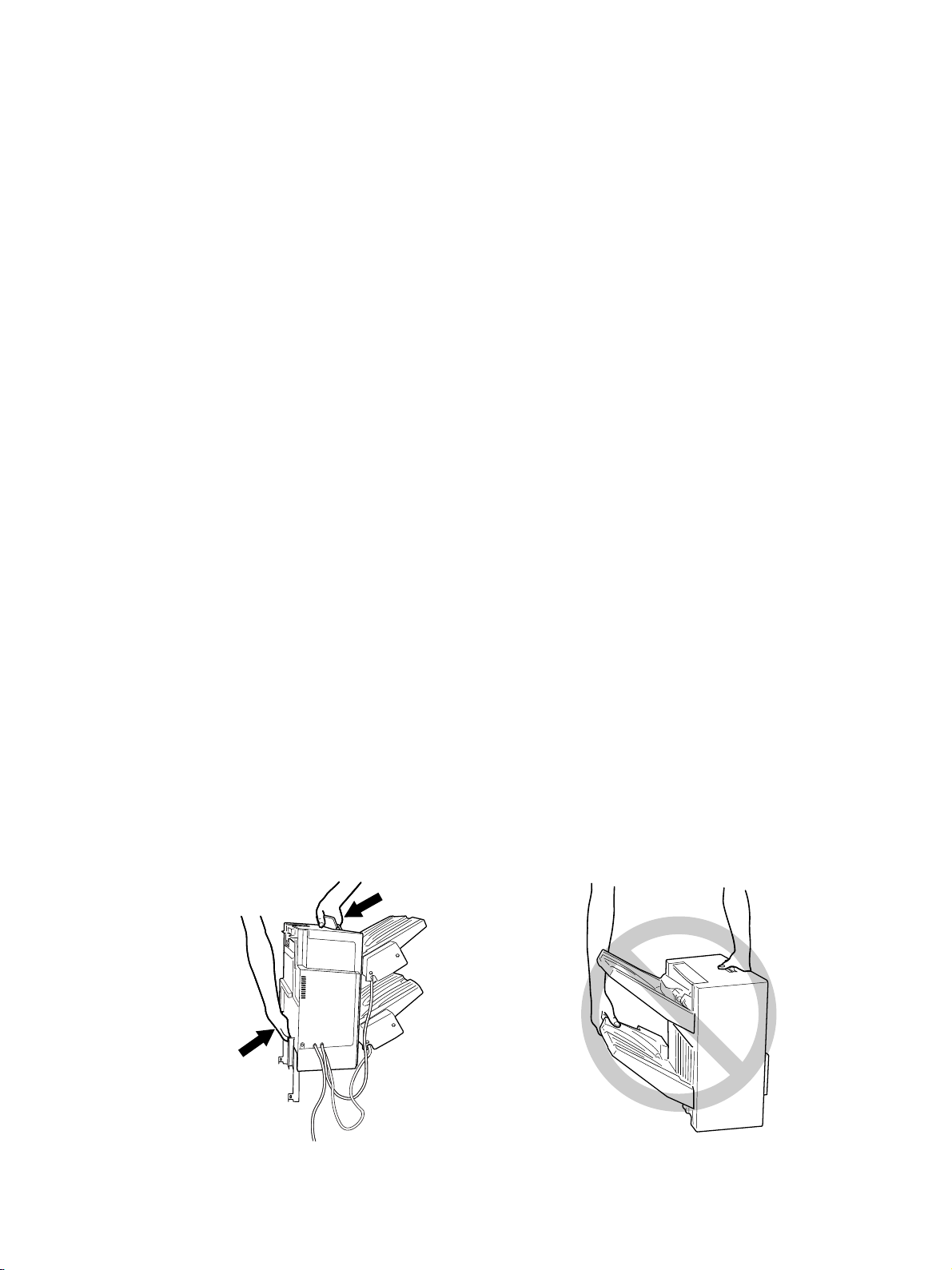
12. When the Finisher is to be carried, be sure to hold the locations shown in the figures.
Page 3
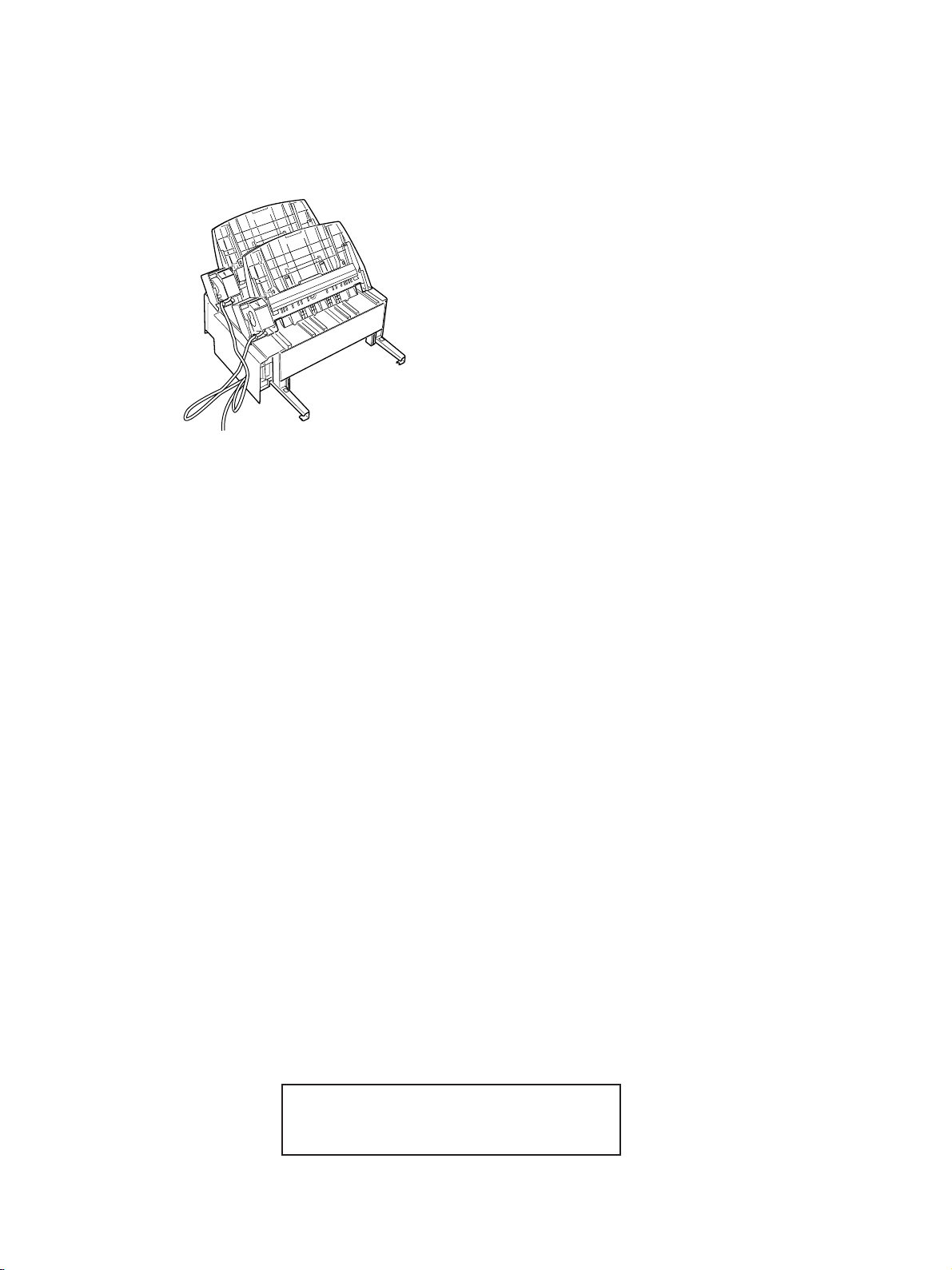
13. Place the finisher as shown in the figure below making sure that the cord is not nipped.
Copyright © 2000
TOSHIBA TEC Corporation
Page 4

INTRODUCTION
This Service Manual contains basic data and figures for the Finisher MJ-1011 needed
to service the machine in the field.
Chapter 1 General Description introduces the finisher's features, specifications, and
names of parts, and shows how to operate the finisher.
Chapter 2 Basic Operation discusses the principles of operation used for the finisher's
mechanical and electrical systems. It also explains the timing at which these
systems are operated.
Chapter 3 Mechanical System discusses how the finisher is constructed mechanically,
and shows how it may be disassembled/assembled and adjusted.
Chapter 4 Maintenance and Inspection provides tables of periodically replaced parts and
consumables and durables, together with a scheduled servicing chart.
Chapter 5 Troubleshooting provides adjustments, problem identification and electrical
parts arrangement.
Appendix containts general timing chart, tables of signals, circuit diagram and
solvent/oils.
For installation, see the Installation Procedure that comes with the finisher.
The descriptions in this Service Manual are subject to change without notice for
product improvement or other purposes, and major changes will be communicated in the
form of Service Information bulletins.
All service persons are expected to have a good understanding of the contents of this
Service Manual and all relevant Service Information bulletins and be able to identify and
isolate faults in the machine.
i
Page 5

CONTENTS
CHAPTER 1 GENERAL DESCRIPTION
I. FEATURES ..................................1-1
II. SPECIFICATIONS .......................1-2
III. OPERATING THE MACHINE ...... 1-6
CHAPTER 2 BASIC OPERATION
I. BASIC CONSTRUCTION ............2-1
II. BASIC OPERATIONS..................2-8
III. FEEDING DRIVE SYSTEM .......2-11
IV. INTERMEDIARY PROCESSING
TRAY ASSEMBLY......................2-13
CHAPTER 3 MECHANICAL SYSTEM
IV. MAINTENANCE BY THE
USER ........................................1-11
V. STAPLING ................................. 2-44
VI. OPERATIONS OF THE STACK
TRAY .........................................2-47
VII. DETECTING JAMS ...................2-56
VIII.POWER SUPPLY ...................... 2-61
I. EXTERNALS AND
CONTROLS.................................3-1
II. FEEDING SYSTEM .....................3-6
III. PROCESSING TRAY ...................3-7
IV. RETURNING ROLLER .............. 3-15
V. STACK TRAY .............................3-22
VI. STACK TRAY LIFTER
UNIT ..........................................3-23
VII. STAPLER...................................3-31
VIII.PCBs ......................................... 3-32
iii
Page 6

CHAPTER 4 MAINTENANCE AND INSPECTION
I. PERIODICALLY REPLACED
PARTS.........................................4-1
II. CONSUMABLES AND
DURABLES .................................4-1
CHAPTER 5 TROUBLESHOOTING
I. ADJUSTMENTS ..........................5-1
II. TROUBLESHOOTING ...............5-12
APPENDIX
III. SCHEDULED MAINTENANCE ...4-1
III. ARRANGEMENT OF ELECTRICAL
PARTS .......................................5-17
A. GENERAL TIMING CHART........ A-1
B. SIGNALS AND
ABBREVIATIONS ....................... A-3
C. GENERAL CIRCUIT
DIAGRAM ................................... A-7
iv
D. FINISHER CONTROLLER
CIRCUIT DIAGRAM ................... A-8
E. SOLVENTS AND OILS ............. A-18
Page 7

CHAPTER 1
GENERAL DESCRIPTION
I. FEATURES ..................................1-1
II. SPECIFICATIONS .......................1-2
III. OPERATING THE MACHINE ...... 1-6
IV. MAINTENANCE BY THE
USER ........................................1-11
Page 8

CHAPTER 1 GENERAL DESCRIPTION
I. FEATURES
1. Small in Size, Light in Weight
• The finisher is designed as a small, light delivery device.
2. Mono-Frame
• The finisher is cased in a mono-frame, which has enabled reduction of the number of covers.
3. Sorting and Stapling by Stack Offset
• The finisher puts together stacks of sheets on its intermediary processing tray for offset
sorting and stapling.
4. Stack Tray
• The finisher’s stack tray is capable of holding as many as 900 sheets (BIN-1: 200 sheets,
BIN-2: 700 sheets) of small-size paper or 450 sheets (BIN-1: 100 sheets, BIN-2: 350 sheets)
of large-size paper.
Further, it can hold as many as 80 sets (BIN-1: 30 sets, BIN-2: 50 sets) of stapled stacks (each
consisting of up to 30 sheets).
1-1
Page 9
CHAPTER 1 GENERAL DESCRIPTION
II. SPECIFICATIONS
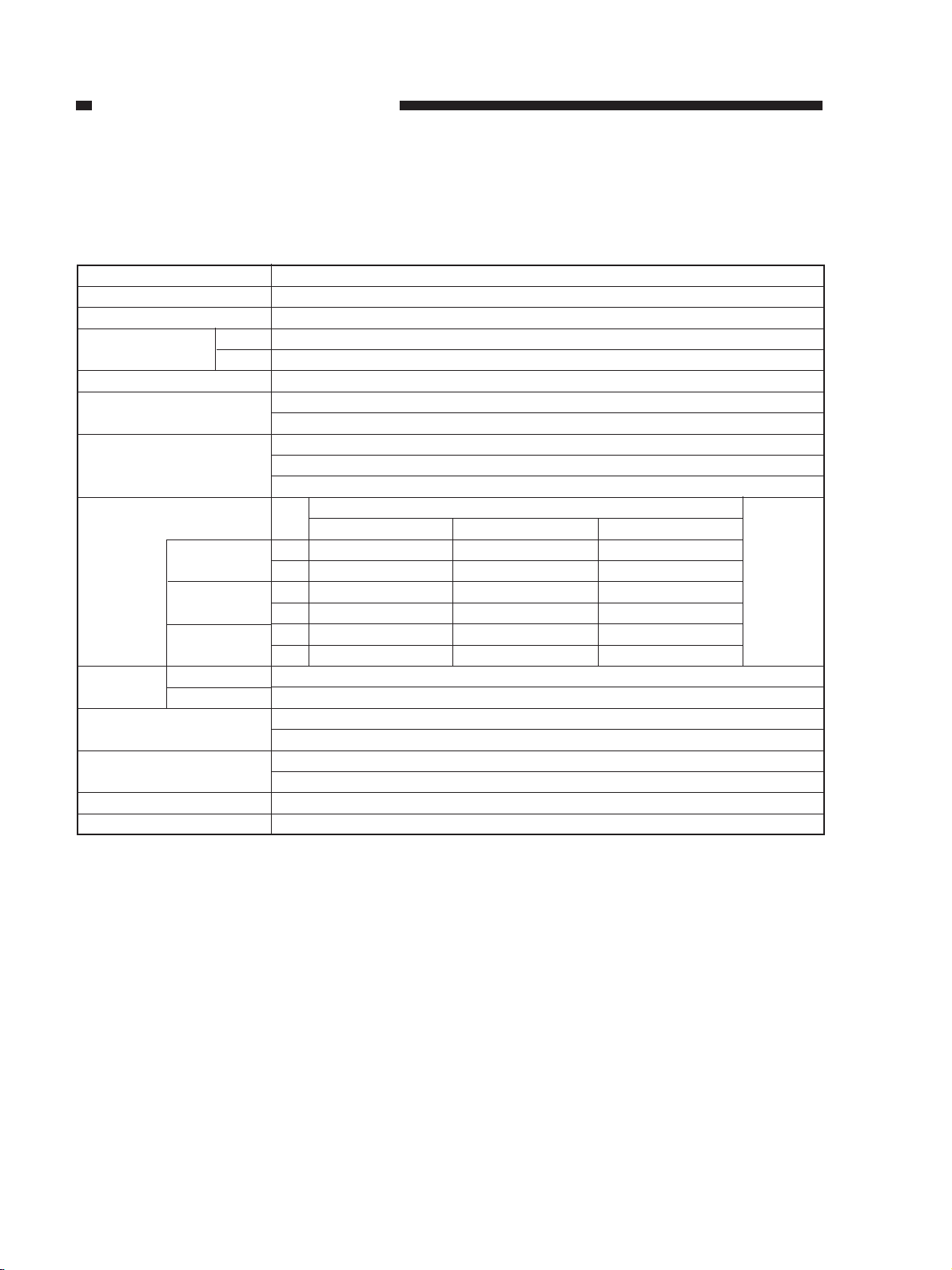
A. Specifications
Item
Stacking
Stacking mode
Stack paper size
Paper weight
Bins
Modes
Stack tray capacity
[height (sheets)]
Simple
stacking
Job offset
Staple
stacking
Stacking
width*4
Stacking size
Stapling size
Stack offset width*6
Offset width*5
Not stapled
Stapled
A/B
Inch
Description
Stack tray (tray lift mechanisms, with intermediary tray fixed in position)
Face-down stacking
A3, A4, A4-R, A5-R, B4, B5, B5-R
LD, LG, LT, LT-R, ST-R, FOLIO, COMPUTER
50 to 200 g/m2 (Plain paper), 64 to 80 g/m2 (Recycled paper)
Stack tray 2
Intermediary processing tray 1
Staple stacking
Non-staple stacking
Non-staple offset stacking
Bin
1 30mm (200 sheets) 20mm (140 sheets) 15mm (100 sheets)
2 99mm (700 sheets) 70mm (490 sheets) 49mm (350 sheets)
1 30mm (200 sheets) 20mm (140 sheets) 15mm (100 sheets)
2 99mm (700 sheets) 70mm (490 sheets) 49mm (350 sheets)
1 30 sets (170 sheets) 30 sets (110 sheets) 30 sets (80 sheets)
2 50 sets (600 sheets) 50 sets (400 sheets) 50 sets (300 sheets)
139.7 to 297 mm
210 to 297 mm
A3, A4, A4-R, B4, B5
LD, LG, LT, LT-R, ST-R, FOLIO, COMPUTER
A3, A4, A4-R, B4, B5
LD, LG, LT, LT-R, FOLIO, COMPUTER
210 to 297 mm
20 mm
Small-size*1 Middle-size*2 Large-size*3
Plain Paper/Recycled Paper
Equivalent
of
80 g/m
paper
2
1-2
Page 10
CHAPTER 1 GENERAL DESCRIPTION
Item
Stapling method
Stapling position
Stack thickness
Staple source
Staple
Staple detection
Manual stapling
Paper detection
Control panel
Display
Dimensions (W×D×H)
Weight
Power supply
Maximum power
consumption
Punching by rotating cam
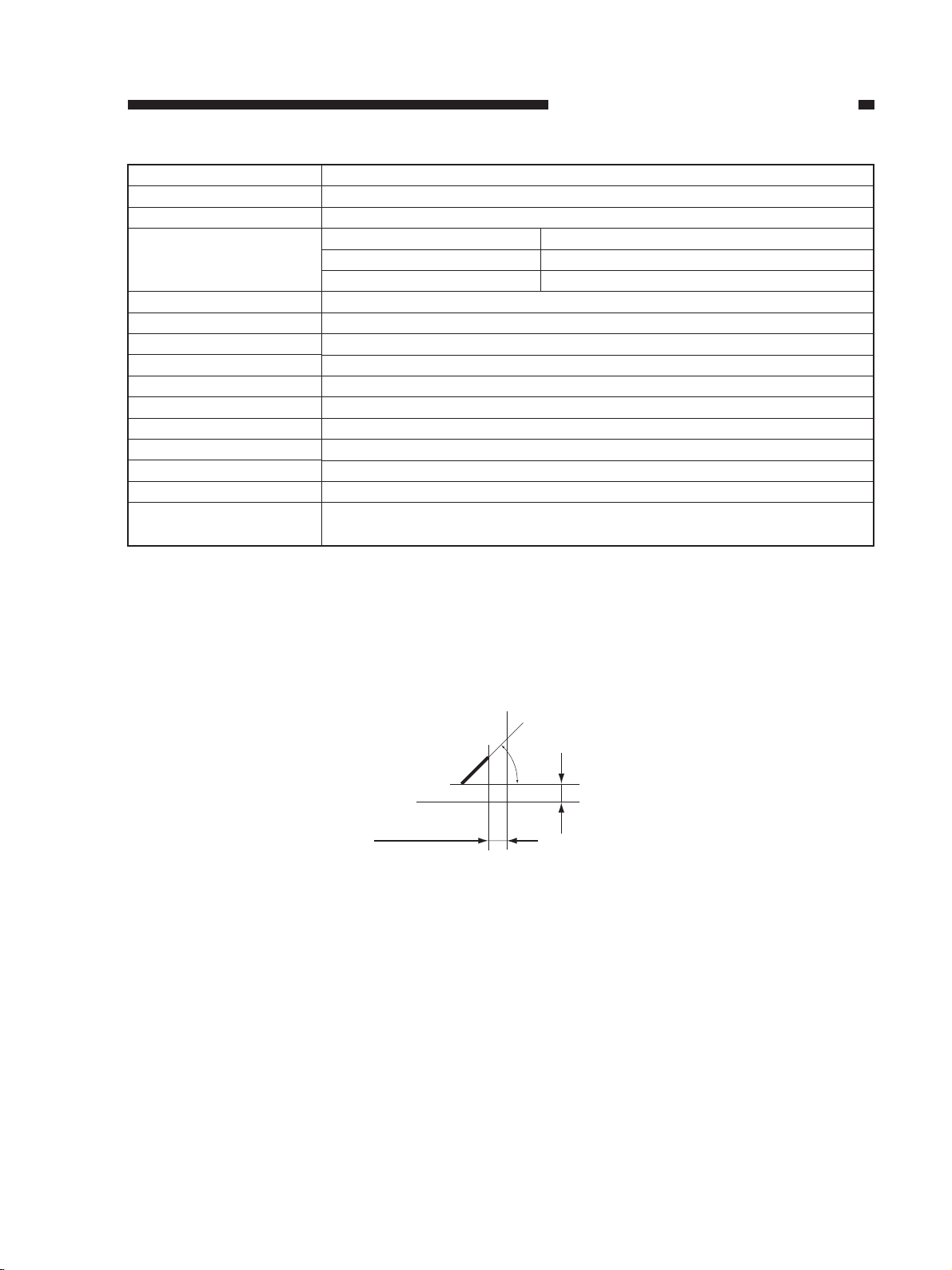
1-point rear, slant (Figure 1-201)
Small-size 30 sheets max.
Medium-size 20 sheets max.
Large-size 15 sheets max.
Special cartridge (3,000 staples)
Special staple (STAPLE-1600)
Yes
No
Yes
No (operated from copier)
None (display on copier)
431 × 541 × 413 mm
17 kg
24V, 5V (from copier)
40W or less
Description
*1 Small-size, i.e., A4, A4-R, A5-R, B5, B5-R, postcard, LT, LT-R and ST-R.
*2 Medium-size, i.e., B4 and LG.
*3 Large-size, i.e., A3, FOLIO, COMPUTER and LD.
*4 The width of paper that may be put into order in the front/rear direction.
*5 The distance a stack is displaced during sorting.
*6 The width of paper that may be put into order during sorting.
45˚
5±4mm
5±4mm
Figure 1-201 Stapling Positions
1-3
Page 11
CHAPTER 1 GENERAL DESCRIPTION
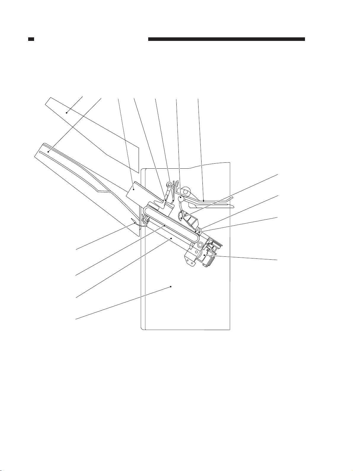
■ Cross Section
[10]
[14]
[1] [2] [3] [4] [5] [6]
[7]
[8]
[11A]
[9]
1-4
[11]
[12]
[13]
[1] Lower stack tray
[2] Jogging plate (front, rear)
[3] Paper feeding guide A
[4] Paper feeding guide B
[5] Delivery roller
[6] Paper path
[7] Returning roller
[8] Stopper plate
[9] Stapler unit
[10] Paper holding lever
[11] Stack delivery belt
[11A] Stack delivery lever
[12] Intermediary processing tray
[13] Frame
[14] Upper stack tray
Figure 1-202
Page 12
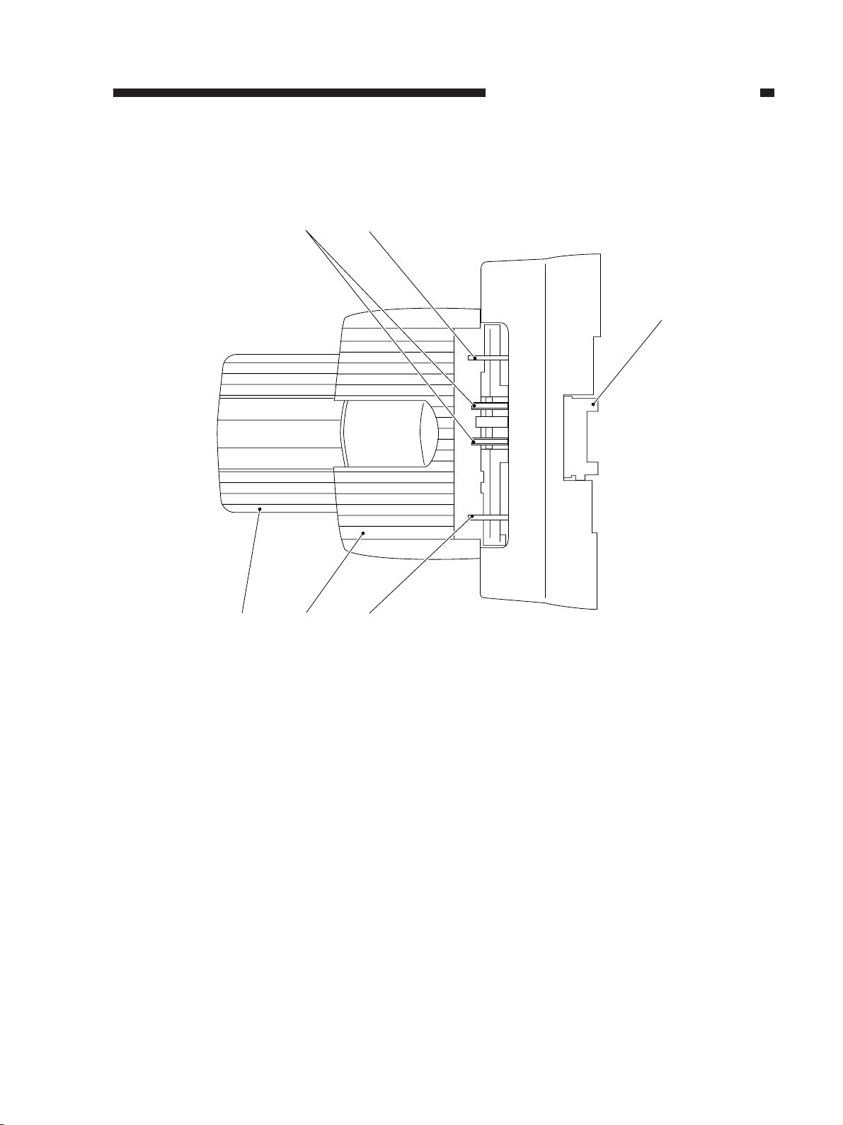
■ Top View
CHAPTER 1 GENERAL DESCRIPTION
[1] [2]
[3]
[4] [5] [6]
[1] Stack delivery belt
[2] Rear jogging plate
[3] Grip
[4] Stack extension tray
[5] Stack tray
[6] Front jogging plate
Figure 1-203
1-5
Page 13
CHAPTER 1 GENERAL DESCRIPTION
III. OPERATING THE MACHINE
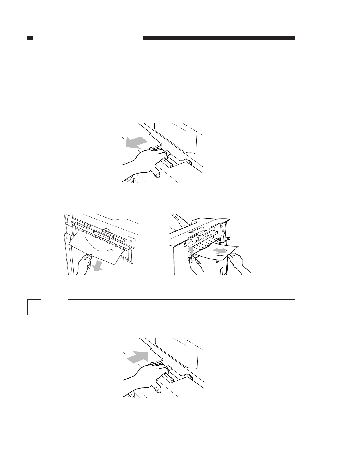
A. Removing Paper Jams
If the Jam indicator is turned on to indicate the presence of a jam in the finisher, perform the
following:
1) Grasping the grip, disconnect the finisher from the copier.
Figure 1-301
2) Remove the paper visible from the outside.
Figure 1-302
Caution:
Do not remove the paper from the intermediary processing tray before removing the jam.
3) Connect the finisher to the copier.
1-6
Figure 1-303
Page 14
CHAPTER 1 GENERAL DESCRIPTION
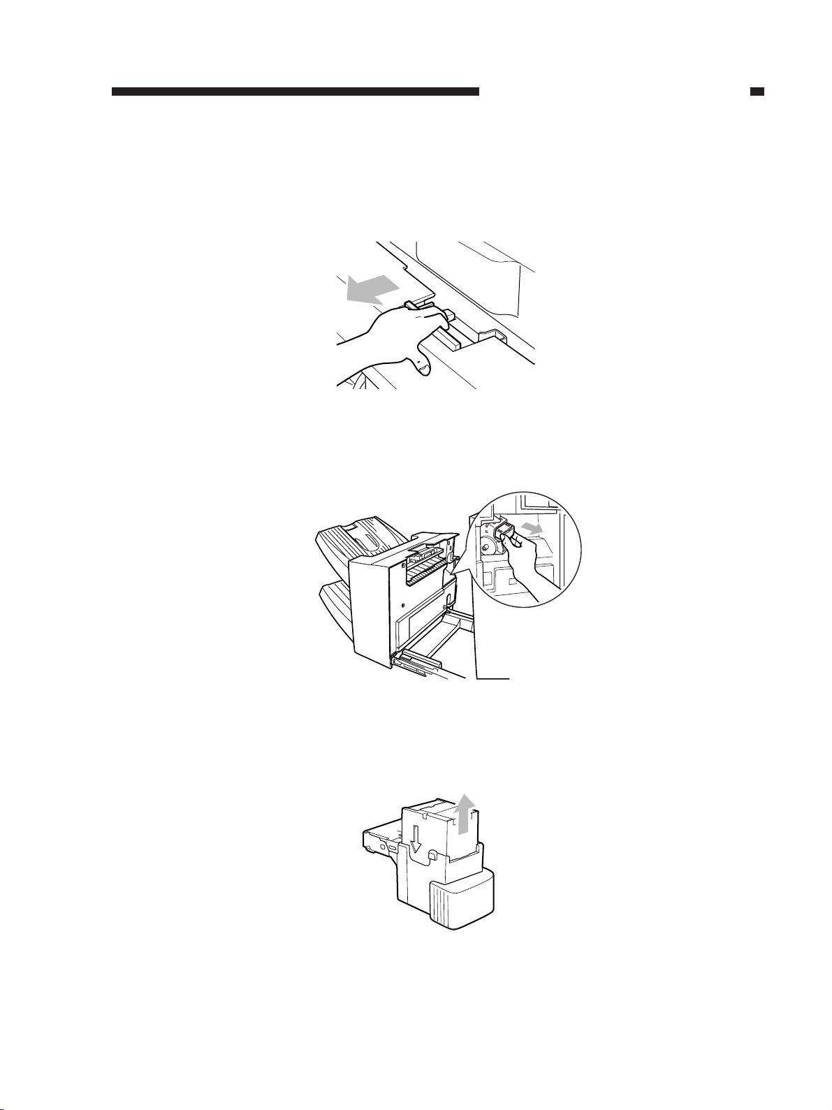
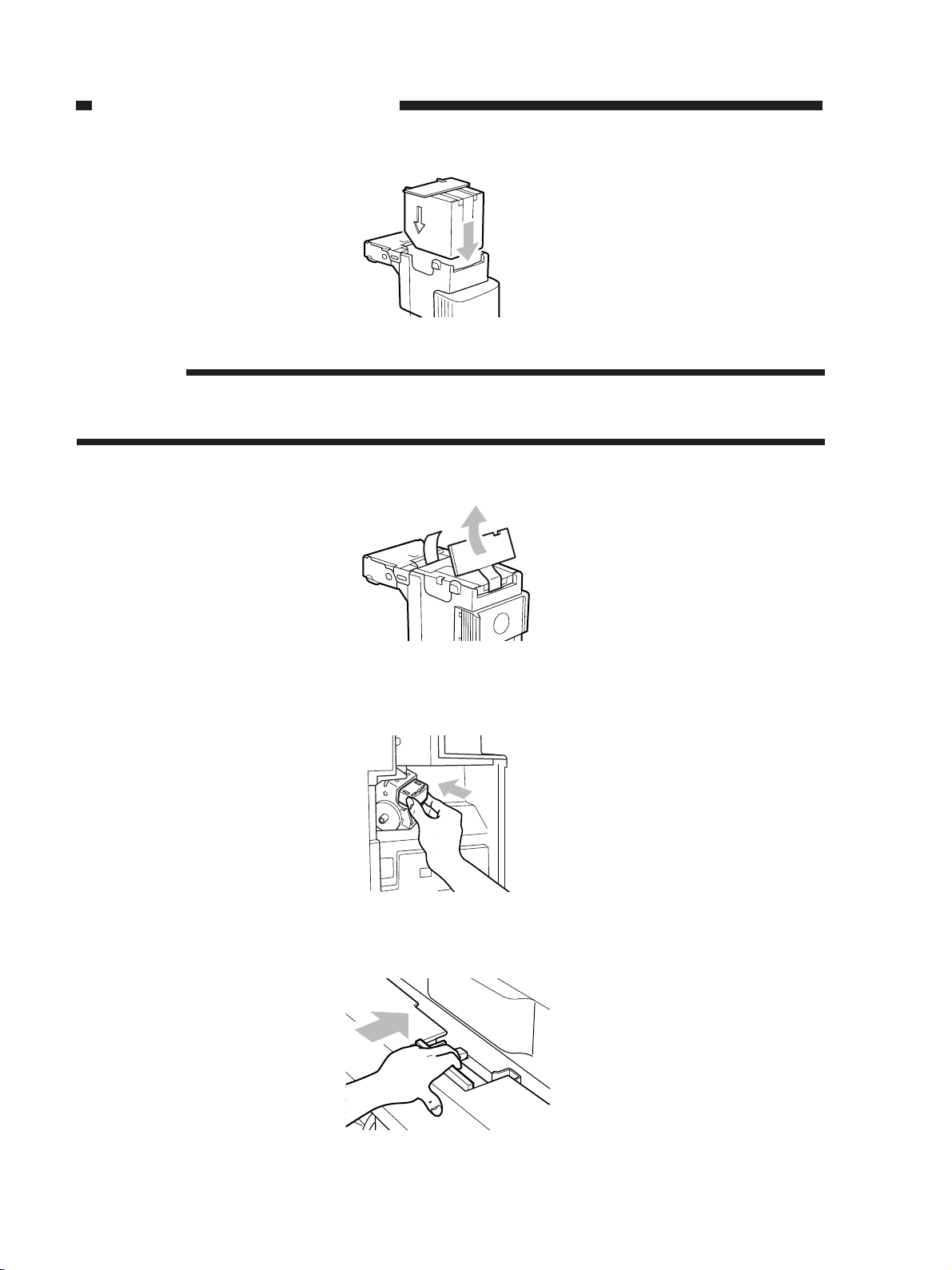
B. Supplying the Stapler Unit with Staples
If the Add Staples indicator turns on, perform the following:
1) Grasping the grip, disconnect the finisher from the copier.
Figure 1-304
2) Pick up the staple cartridge by its left and right side (light blue) and pull it off.
Figure 1-305
3) Pick up the empty staple case by its left and right side and pull it off.
Figure 1-306
1-7
Page 15
CHAPTER 1 GENERAL DESCRIPTION
4) Set the new staple case.
Figure 1-307
Reference:
No more than one staple case may be set. Be sure to use a staple cartridge specially designed for
the machine.
5) Remove the seal used to hold the staples together by pulling it straight up.
Figure 1-308
6) Fit the staple cartridge into the stapler unit.
Figure 1-309
7) Connect the finisher to the copier.
1-8
Figure 1-310
Page 16
CHAPTER 1 GENERAL DESCRIPTION
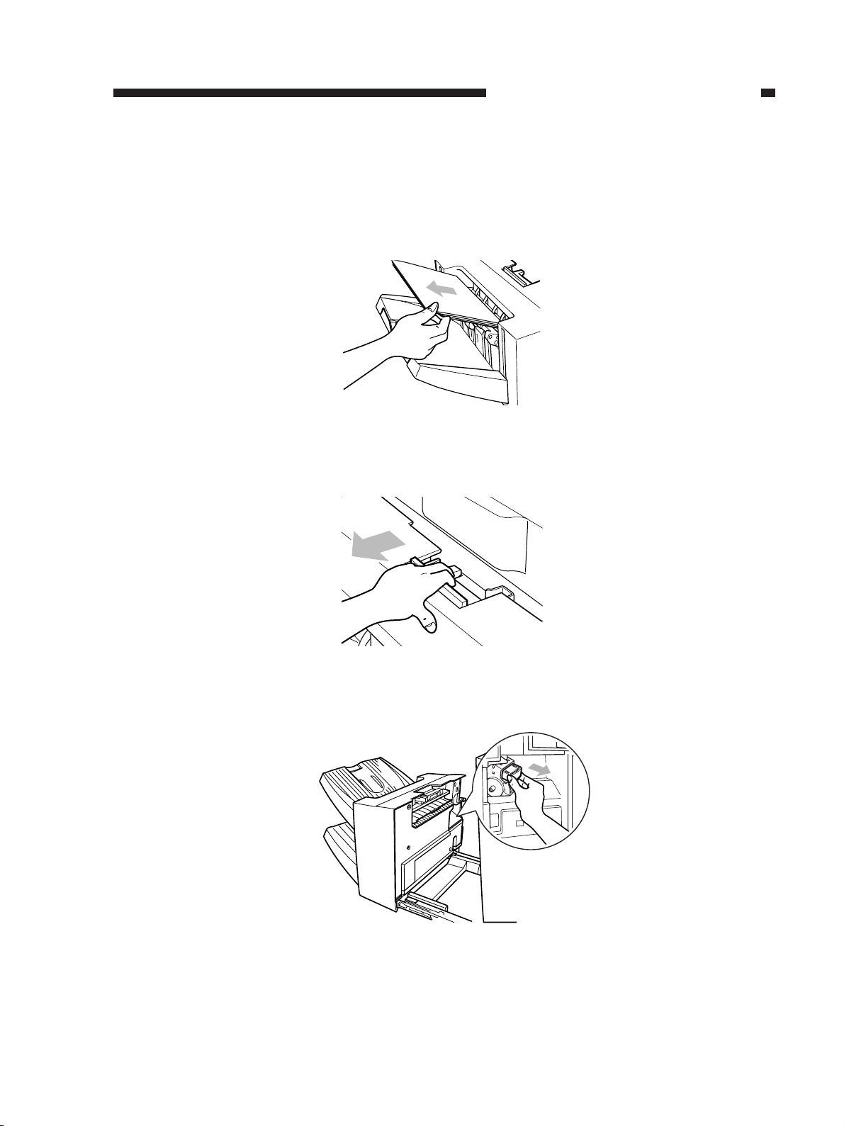
C. Removing a Staple Jam from the Stapler Unit
If the Staple Jam indicator turns on to indicate a staple jam in the stapler unit, perform the
following:
1) Remove the paper waiting to be stapled from the processing tray.
Figure 1-311
2) Grasping the grip, disconnect the finisher from the copier.
Figure 1-312
3) Pick up the staple cartridge by its left and right side (light blue) and pull it off.
Figure 1-313
1-9
Page 17
CHAPTER 1 GENERAL DESCRIPTION
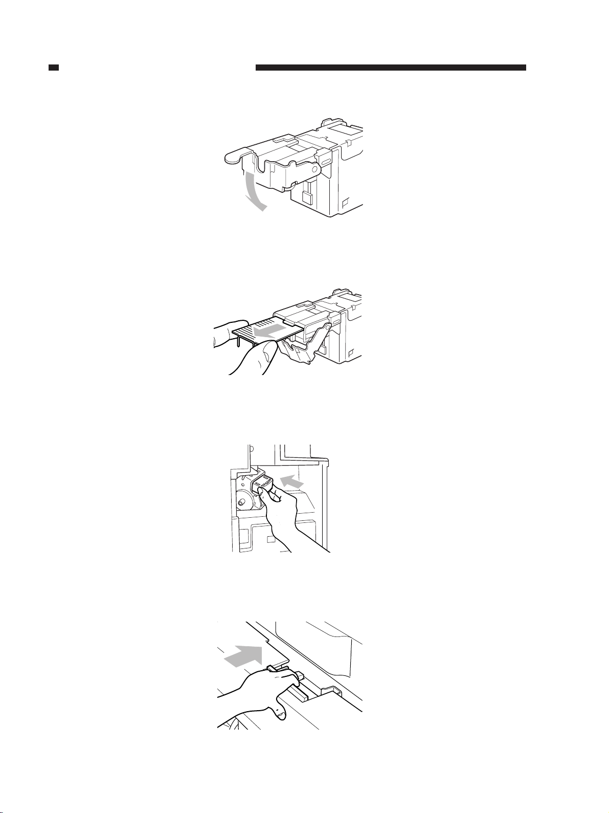
4) Shift down the staple cartridge.
Figure 1-314
5) Remove all staples that slid out of the staple case.
Figure 1-315
6) Shift the tab of the staple cartridge back to its initial position, and fit the staple cartridge into the
stapler unit.
Figure 1-316
7) Connect the finisher to the copier.
1-10
Figure 1-317
Page 18
CHAPTER 1 GENERAL DESCRIPTION
IV. MAINTENANCE BY THE USER
A. Maintenance by the User
No.
Replacement of the staple cartridge
1
Item
Timing
When prompted on the copier’s display
Table 1-401
1-11
Page 19

CHAPTER 2
BASIC OPERATION
I. BASIC CONSTRUCTION ............2-1
II. BASIC OPERATIONS ..................2-8
III. FEEDING DRIVE SYSTEM .......2-11
IV. INTERMEDIARY PROCESSING
TRAY ASSEMBLY......................2-13
V. STAPLING ................................. 2-44
VI. OPERATIONS OF THE STACK
TRAY .........................................2-47
VII. DETECTING JAMS ...................2-56
VIII.POWER SUPPLY ...................... 2-61
Page 20
CHAPTER 2 BASIC OPERATION
I. BASIC CONSTRUCTION
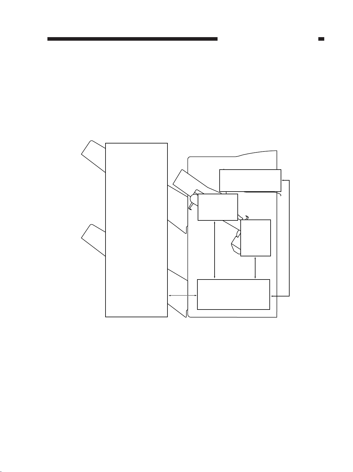
A. Outline
The finisher consists of four blocks: intermediary processing tray assembly, stapler assembly,
and stack tray assembly. Figure 2-101 is a functional diagram of the finisher.
Delivery assembly
Intermediary
processing
tray assembly
Stack tray
assembly
Stapler
assembly
Figure 2-101
Finisher controller
PCB
2-1
Page 21
CHAPTER 2 BASIC OPERATION
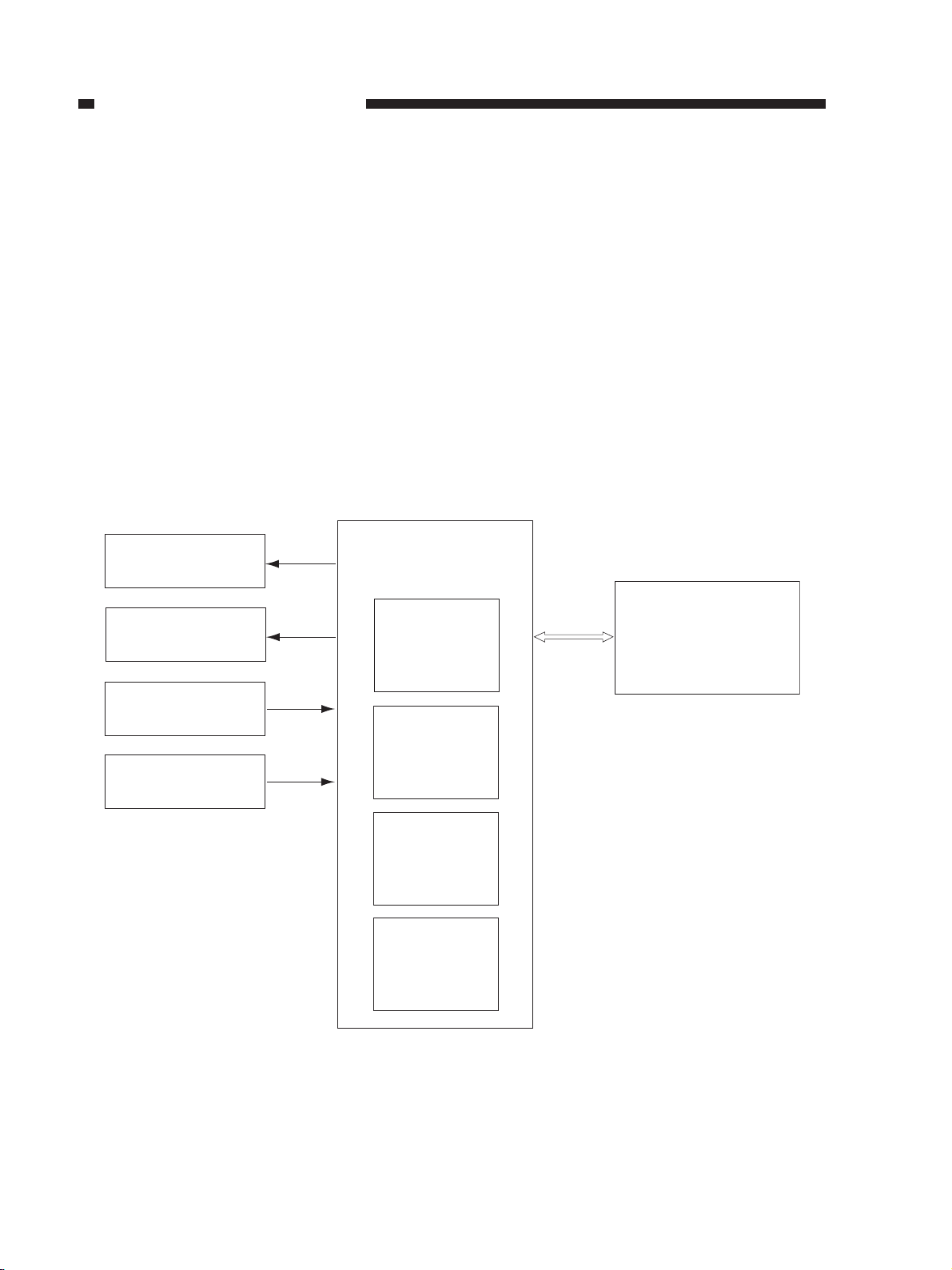
B. Outline of Electrical Circuitry
The finisher’s operation sequences are controlled by the finisher controller PCB, which is a 32-
bit CPU. The finisher controller PCB is also used to control communication (serial) with the copier.
The CPU on the finisher controller PCB is equipped with a built-in ROM used to store
operation sequence programs.
The finisher controller PCB drives solenoids, motors etc., in response to various commands
coming from the copier through serial communication lines. On the other hand, it communicates
the state of each sensor and switch to the copier in the serial mode of communication.
The ICs on the finisher controller PCB have the following functions:
■ IC1 (CPU): Controls sequence
■ IC2 (RAM): Stores various kinds of data temporarily
■ IC3 (ROM): Stores sequence program
■ IC4 (Communication IC): Communicates with the copier
Finisher controller
Solenoid
PCB
Motor
Sensor
Switch
IC1
CPU
IC2
RAM
IC3
ROM
IC4
Communication
IC
Copier
(CPU on DC
controller PCB)
2-2
Figure 2-102
Page 22
CHAPTER 2 BASIC OPERATION
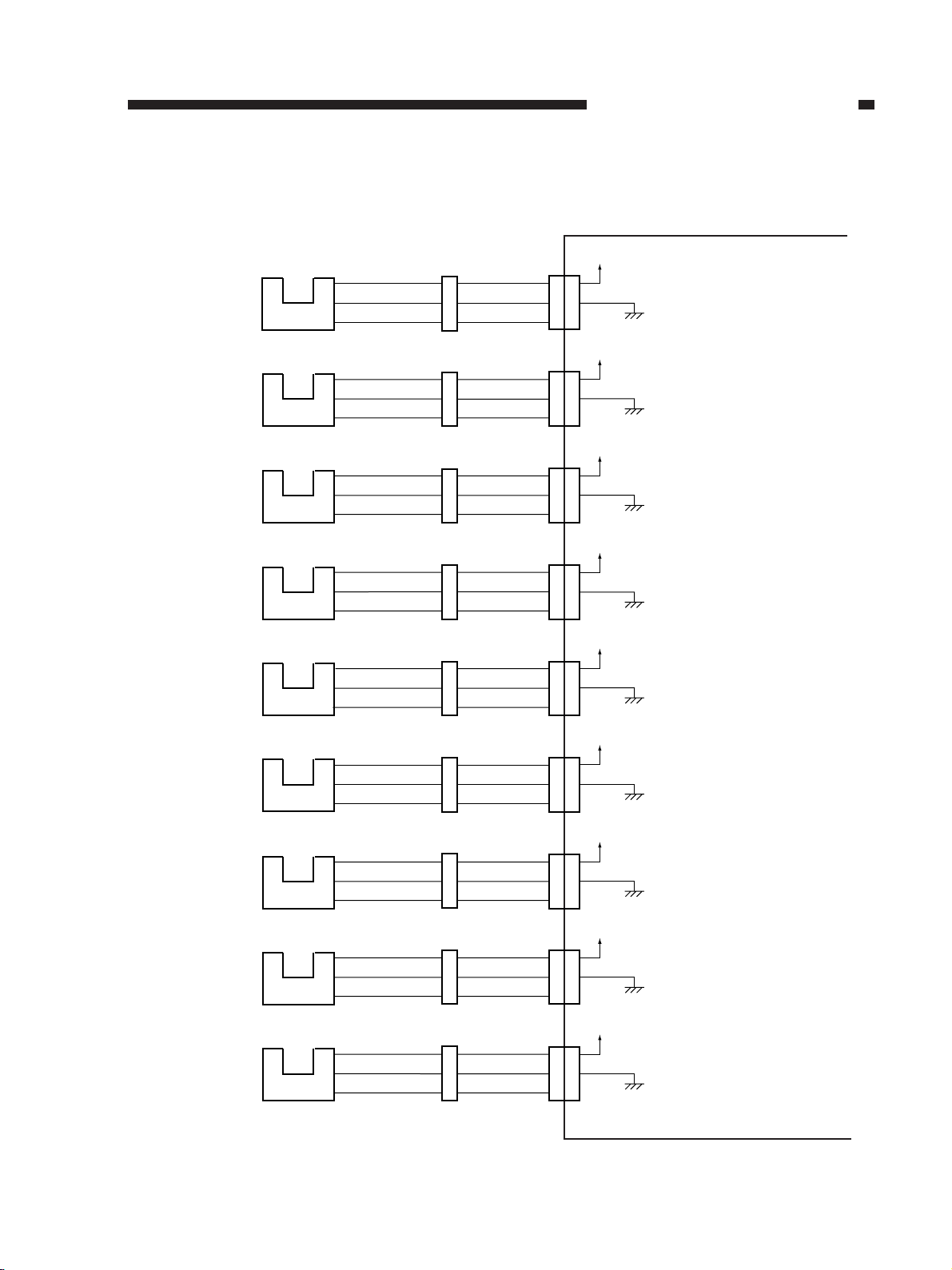
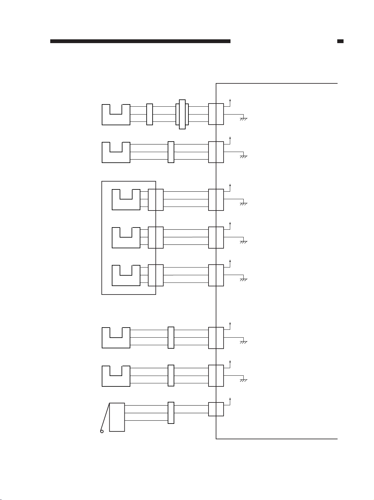
C. Inputs to and Outputs from the Finisher Controller PCB
• Inputs to the Finisher Controller PCB (1/3)
Delivery motor
clock sensor
Inlet paper sensor
Returning roller
home position sensor
Finisher joint sensor
Intermediary
processing tray
paper sensor
S1
S2
S3
S4
S5
J602
J605
J606
J609
J504
J601
J601
J601
J608
J501
Finisher controller PCB
J10
A1
A2
A3
B1
B2
B3
B4
B5
B6
A1
A2
A3
7
8
9
J10
J10
J11
J9
S1D
S2D
S3D
S4D
S5D
+5V
Pulses according to the rotation
speed of the delivery motor.
+5V
When paper is moving over
the sensor, '1'.
(The light-detecting plate is at S2.)
+5V
When the returning roller is
at the home position, '1'.
(The light-blocking plate is at S3.)
+5V
When the finisher is connected
to the copier, '0'.
(The light-blocking plate is not at S4.)
+5V
When paper is over the sensor, '1'.
(The light-blocking plate is at S5.)
A1
A2
A3
B1
B2
B3
B4
B5
B6
A1
A2
A3
7
8
9
Front jogging plate
home position sensor
Rear jogging plate
home position sensor
Stack delivery lever
home position sensor
Lower stack tray lift
motor clock sensor
S6
S7
S8
S9
J502
J503
J505
J603
Figure 2-103
J501
J501
J501
J601
10
11
12
A4
A5
A6
J9
1
2
3
4
5
6
10
11
12
A4
A5
A6
J9
J9
J10
S6D
S7D
S8D
S9D
+5V
When the front jogging plate is
at the home position, '1'.
(The light-blocking plate is at S6.)
+5V
When the rear jogging plate is
at the home position, '1'.
(The light-blocking plate is at S7.)
+5V
The stack delivery plate is
at the home position, '0'.
(The light-blocking plate is not at S8.)
+5V
Pulses according to the rotation speed
of the lower stack tray lift motor.
1
2
3
4
5
6
2-3
Page 23
CHAPTER 2 BASIC OPERATION
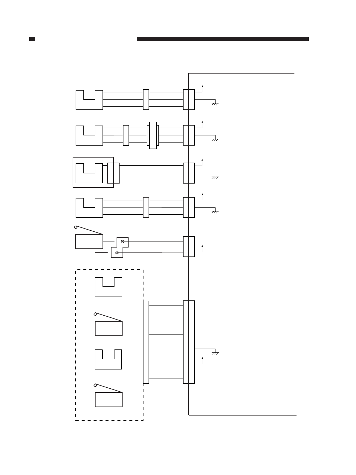
• Inputs to the Finisher Controller PCB (2/3)
Stack tray paper
height sensor
Lower stack tray
paper sensor
Lower stack tray
lower limit sensor
Lower stack tray
upper limit sensor
Stapler safety
switch
S10
S11
S12
Sonser PCB
S13
S14
J1102 J1101 J902
J612
J612
11
11
12
12
13
13
N.O.
COM
J607
J611
Finisher controller PCB
J601
J10
+5V
B7
B7
B8
B8
S10D
B9
B9
J901
J15
1
2
3
J11
B3
B2
B1
J11
A7
A8
A9
J7
1
+5V
S10D
+5V
S12D
+5V
S13D
S14D
+24V
1
2
3
J608
B3
B2
B1
J608
A7
A8
A9
J801
212
When the top of paper is
detected,
'1'.
(The light-blocking is at S10.)
When paper is over the lower stack
tray paper sensor,
'1'.
(The light-blocking plate is at S11.)
When the lower stack tray is
at the lower limit,
'1'.
(The light-blocking plate is at S12.)
When the upper stack tray is
at the upper limit,
'1'.
(The light-blocking plate is not at
S13.)
When the switch is open,
'1'.
Staple edging
sensor
No-staple
detecting switch
Stapling home
position sensor
Stapler cartridge
detector switch
2-4
S15
S16
S17
S18
Stapler unit
J402
13
8
9
11
12
7
Figure 2-104
J401
13
13
8
9
11 11
12 12
7
8
9
7
J8
S15D
S16D
S17D
+5V
S18D
The tip of the staple is not at the
stapling position,
(The light-blocking plate is not at S15.)
When the stapler has no staples, '1
When the stapler is at the stapling
home position,
(The light-blocking plate is at S17.)
When the stapler cartridge is not set,
'1'.
'.
'0'.
'1'.
Page 24
• Inputs to the Finisher Controller PCB (3/3)
10
J612
2
2
3
3
4
4
J612
5
5
6
6
7
7
J612
8
8
9
9
10
J704 J604
J702
Upper stack tray
lift motor
clock sensor
Upper stack tray
paper sensor
Stack tray
nearly full sensor
Upper stack tray
full sensor
Lower stack tray
full sensor
J705
S19
S20
J612
S21
J612
S22
J612
S23
Sensor PCB
J601
J701
J608
J608
J608
CHAPTER 2 BASIC OPERATION
Finisher controller PCB
J10
A7
A8
A9
J12
1
2
3
J11
B12
B11
B10
J11
B9
B8
B7
J11
B6
B5
B4
+5V
S19D
+5V
S20D
+5V
S21D
+5V
S22D
+5V
S23D
Pulses according to the rotation
speed of the upper stack tray
lift motor
When the paper is over the upper
stack tray paper sensor, '1'
(The light-blocking plate is at S20.)
When the upper/lower stack tray is
at the nearly full position, '1'
(The light-blocking plate is at S21.)
When the upper stack tray is
at the full position, '1'
(The light-blocking plate is at S22.)
When the lower stack tray is
at the full position, '1'
(The light-blocking plate is at S23.)
A7
A8
A9
1
2
3
B12
B11
B10
B9
B8
B7
B6
B5
B4
Stack tray collision
prevention sensor
Upper stack tray
upper limit sensor
Stack processing
safety switch
S24
S25
S26
COM
N.O.
J703
J610
J1202
Figure 2-105
J701
J608
A4
A5
A6
J1201
J12
4
5
6
A4
A5
A6
1
22
J11
J16
+5V
S24D
+5V
S25D
+24V
S26D
When the upper stack tray collides
with paper stacked on the lower
stack tray, '1'
(The light-blocking plate is at S24.)
When the upper stack tray is
at the upper limit, '1'
(The light-blocking plate is at S25.)
When the switch is open, '1'.
4
5
6
1
2-5
Page 25
CHAPTER 2 BASIC OPERATION
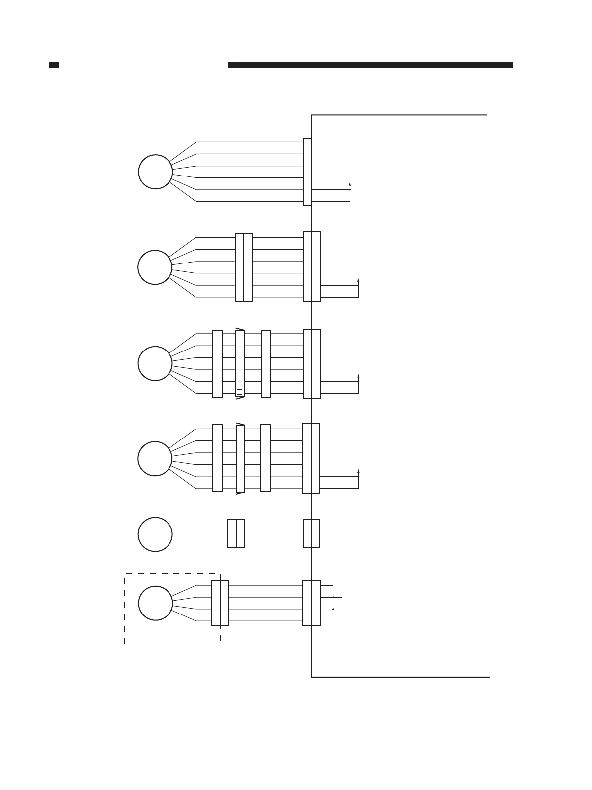
• Outputs of the Finisher Controller PCB (1/2)
Delivery motor
Stack processing
motor
M1
J202J203
M2
Finisher controller PCB
J4
1
M1DA
2
M1DB
3
M1DA*
4
M1DB*
5
24V
6
J5
J201
1
1
M2DA
2
2
M2DB
3
3
M2DA*
4
4
M2DB*
5
5
6
6
By changing the sequence of drive
pulses (A, A*, B, B*) and the
frequency, the timing of the rotation
is controlled.
By changing the sequence of drive
pulses (A, A*, B, B*) and the
frequency, the timing of the rotation
is controlled.
(See p. 2-14)
24V
Front jogging motor
Rear jogging motor
Upper stack tray lift
motor
Stapler motor
M3
M4
M5
M6
Stapler unit
J306
J708
J402
J304
J305J307
J707
J302
J303
J301
J301
J401
10
11
12
J6
1
1
M3DA
2
2
M3DB
3
3
M3DA*
4
4
M3DB*
5
5
6
6
By changing the sequence of drive
pulses (A, A*, B, B*) and the
frequency, the timing of the rotation
is controlled.
24V
(See p.2-30.)
J6
7
7
M4DA
8
8
M4DB
9
9
M4DA*
10
M4DB*
11
12
J14J706
M5D1
121
2
M5D2
By changing the sequence of drive
pulses (A, A*, B, B*) and the
frequency, the timing of the rotation
is controlled.
(See p. 2-30)
24V
CW rotation at M5D1
CCW rotation at M5D1 '1', M5D2 '0
Stop at M5D1 '0', M5D2 '0
'0',
M5D2 '1
'.
'.
'.
J8
1
1
2
2
4
4
5
5
M6D1
M6D2
CW rotation at M6D1
CCW rotation at M6D1 '1', M6D2 '0
Stop at M6D1 '0', M6D2 '0
'0',
M6D2 '1
'.
'.
'.
2-6
Figure 2-106
Page 26
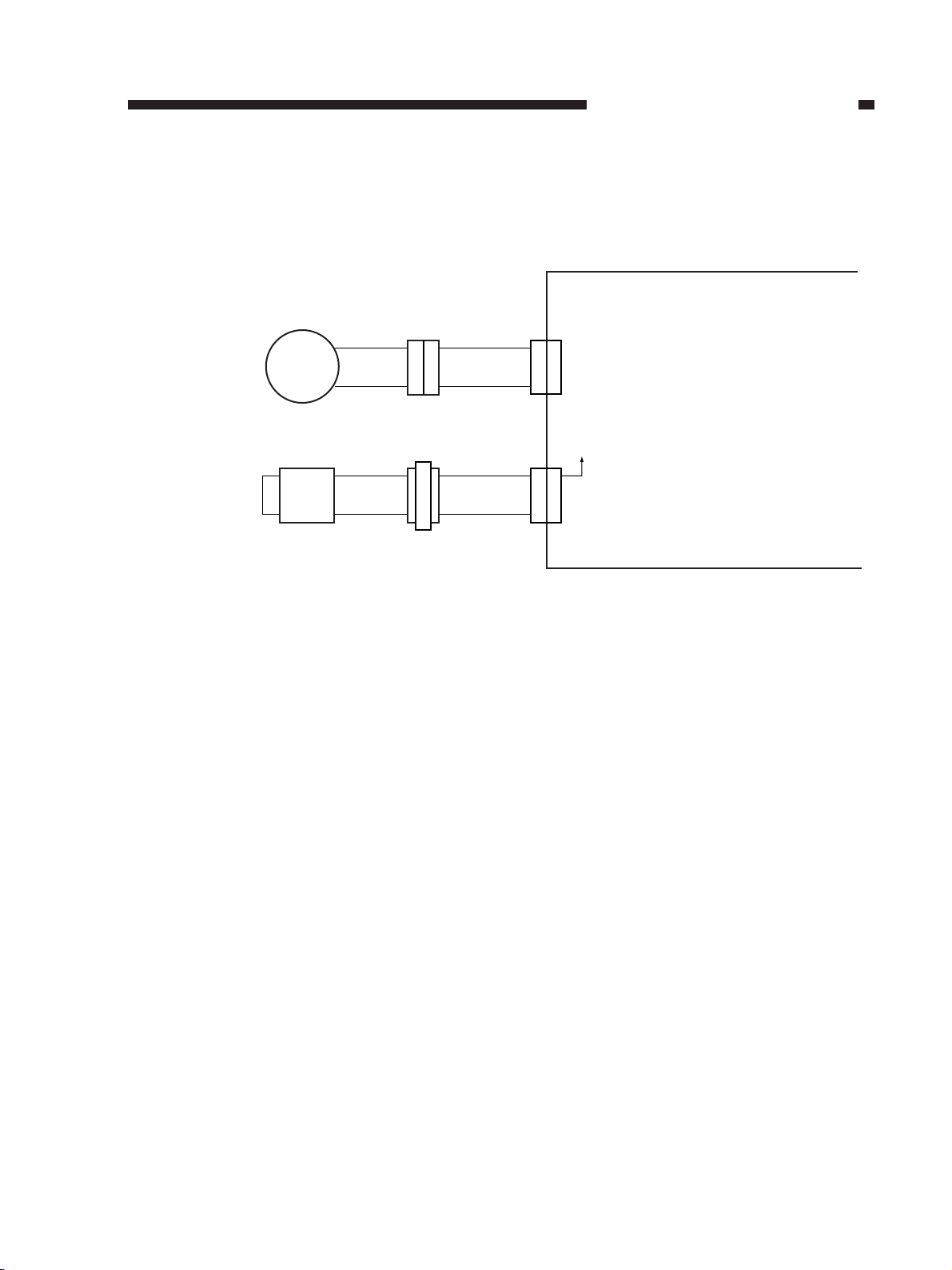
• Outputs of the Finisher Controller PCB (2/2)
Lower stack tray
lifter motor
Paper holding lever
drive solenoid
M7
J1006 J1005
SL1
J1001J1003 J1002
J1004
CHAPTER 2 BASIC OPERATION
Finisher controller PCB
121
121
J3
2
J13
2
M7D1
M7D2
24V
SL1D
CW rotation at M7D1"0", M7D2"1"
CCW rotation at M7D1"1", M7D2"0"
Stop at M7D1"0", M7D2"0"
Solenoid ON at SL1D"0"
Figure 2-107
2-7
Page 27
CHAPTER 2 BASIC OPERATION
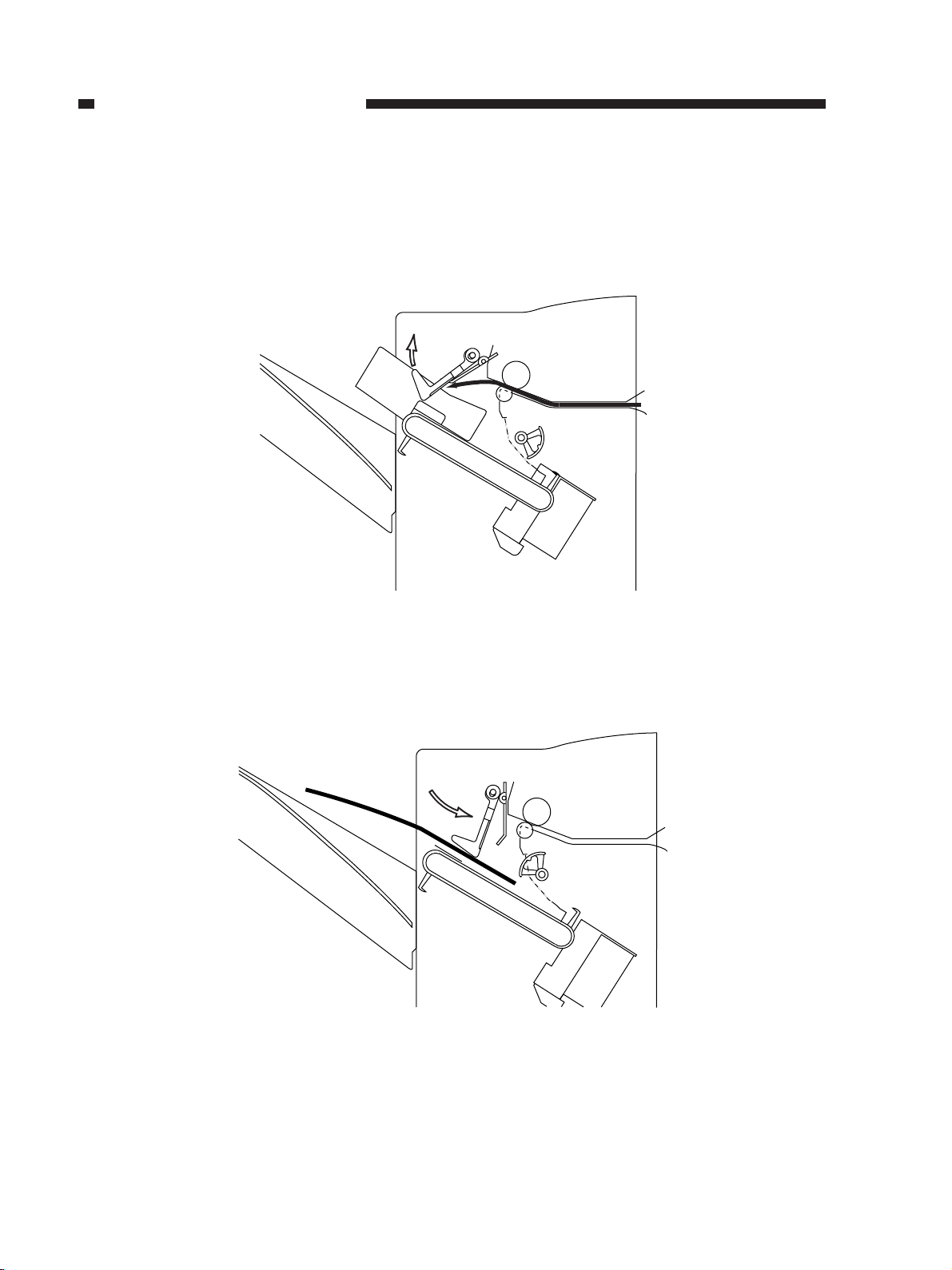
II. BASIC OPERATIONS
The finisher is designed to operate as follows:
1. Paper arrives from the copier.
Figure 2-201
2. Paper reaches the intermediary processing tray.
Figure 2-202
2-8
Page 28
CHAPTER 2 BASIC OPERATION
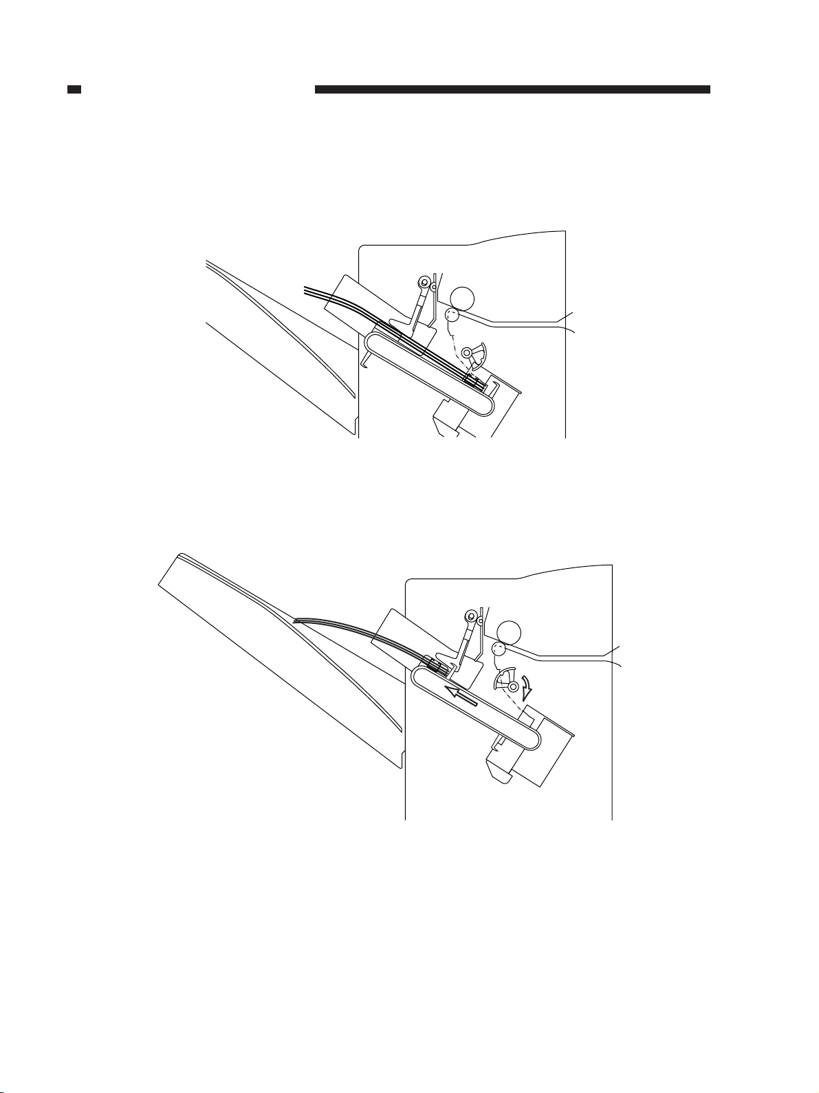
3. Paper is moved until it butts against the stopper plate by the work of the returning roller.
Figure 2-203
4. The paper is put into order by the work of the front/rear jogging plate.
Figure 2-204
2-9
Page 29
CHAPTER 2 BASIC OPERATION
5. Operations 1 through 4 are repeated until a specific number of sheets have been stacked on the
intermediary processing tray.
6. The sheets are stapled (if stapling is selected).
Figure 2-205
7. The stack on the intermediary processing tray is moved to the stack tray.
Figure 2-206
2-10
Page 30
CHAPTER 2 BASIC OPERATION
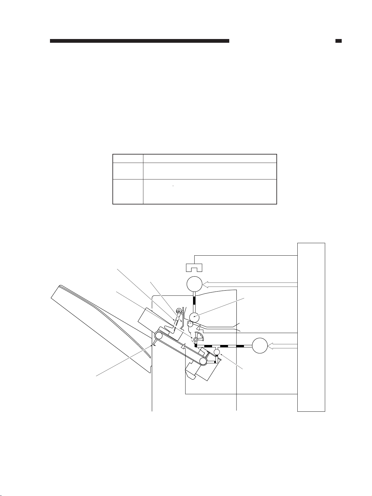
III. FEEDING DRIVE SYSTEM
A. Outline
Paper coming from the copier is sent to the intermediary processing tray, on which it is
arranged and offset/stapled for delivery to the stack tray.
The machine detects jams using the inlet sensor (S2).
Figure 2-301 shows the construction of the feeding drive system.
Notation
M1
M2
Feeding guide A
Returning roller
Delivery motor
Stack processing motor
S1
S2
S5
Delivery motor clock sensor
Inlet sensor
Intermediary processing tray paper sensor
Feeding guide B
Name
Table 2-301
S1
M1
S2
J10A-3
S1D
J4
Delivery roller
J10B-3
S2D
M2
Finisher controller PCB
J5
Stack delivery lever
S5
One-way clutch
J9-9
S5D
Figure 2-301
2-11
Page 31

CHAPTER 2 BASIC OPERATION
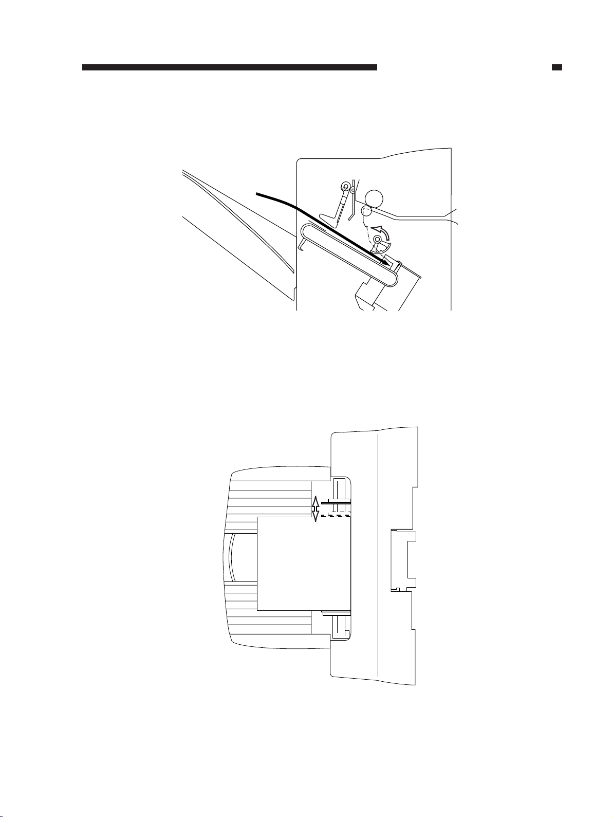
B. Delivery
Paper coming from the copier is sent to the intermediary processing tray by the work of the
delivery motor (M1), and the movement of paper is monitored by the inlet sensor (S2).
The delivery slot of the machine is equipped with a feeding guide (A/B). The feeding guide A/
B holds down the trailing edge of paper using its own weight so as to help move paper as far as the
returning roller.
Feeding guide A
Feeding guide B
Delivery roller
S2
Figure 2-302
2-12
Page 32

CHAPTER 2 BASIC OPERATION
IV. INTERMEDIARY PROCESSING TRAY ASSEMBLY
A. Intermediary Processing Tray Operation
1. Outline
The intermediary processing tray is designed to organize sheets coming from the copier into a
stack for offset and stapling operations.
The intermediary processing tray assembly consists of a returning roller and stack delivery
belts, the latter of which are equipped with stack delivery levers and operate as a pair.
When paper reaches the intermediary processing tray, the intermediary processing tray paper
sensor (S5) is turned on.
When the copier is turned on, the stack processing motor (M2) is driven so as to move the
returning roller and the stack processing belt to the home position.
Returning roller home position sensor (S3)
Stack processing
motor
M2
Motor direction
Clockwise
Counterclockwise
One-way clutch
Stack delivery belt
Figure 2-401
Drive
Stack delivery belt
Returning roller
Returning roller
Returning roller
Arrow in Figure 2-401
Stack tray side
Drive torque
Strong
Weak
Table 2-401
2-13
Page 33

CHAPTER 2 BASIC OPERATION
2. Controlling the Stack Processing Motor (M2)
The stack processing motor (M2) is a 4-phase stepping motor.
The direction of the rotation (clockwise/counterclockwise) and the speed of the motor are
controlled by the phase of the pulse signals BUNDPINA and BUNDPINB from the CPU to IC10,
which generates pulse signals A, A*, B, B* in response for control.
The motor torque is controlled based on combinations of current control signals BUNDCUR1
and BUNDCUR2 from the CPU to IC10.
The machine drives the motor using a high torque when rotating it clockwise (to drive the stack
delivery belt); on the other hand, it drives the motor at a low torque when rotating it
counterclockwise (to drive the returning roller).
IC1
CPU
BUNDPINA
BUNDPINB
BUNDCUR1
BUNDCUR2
IC10
Motor
driver
Figure 2-402
A
A*
B
B*
24V
J5-1
-5
-3
-2
-6
-4
Stack processing
motor
M2
2-14
Page 34

CHAPTER 2 BASIC OPERATION
3. Stacking Limit on the Intermediary Processing Tray
The intermediary processing tray is capable of holding as many sheets of paper as are indicated
in Table 2-402.
When a specific count is exceeded (copies or originals), as many sheets as indicated are put
into order and offset on the intermediary processing tray; then, the stack is delivered to the stack
tray to deal with the remaining number of sheets.
For offset, all sheets of the same stack are moved in the same direction.
Large-size
15
Cassette
Paper deck
Small-size30Medium-size
20
Small-size: A4, A4-R, A5-R, B5, B5-R, postcard, LT, LT-R,
ST-R
Medium-size: B4, LG
Large-size: A3, FOLIO, COMP, LD
Table 2-402
2-15
Page 35

CHAPTER 2 BASIC OPERATION
B. Returning Roller
1. Outline
The returning roller serves to butt paper from the copier against the stopper plate to correct its
placement in the feeding direction.
The returning roller is driven in a clockwise direction when the stack processing motor rotates
counterclockwise.
Returning roller
Stopper plate
Figure 2-403
2-16
Page 36

CHAPTER 2 BASIC OPERATION
2. Outline of Operations
The returning roller operates as follows:
1. Paper arrives from the copier.
Figure 2-404a
2. The returning roller rotates clockwise to butt the paper reaching the intermediary processing
tray against the stopper plate.
Stopper plate
Figure 2-404b
3. The returning roller makes a single rotation and waits in its home position. In the case of
large-/medium-size paper, it waits where it will hold down the paper in position.
Figure 2-404c
2-17
Page 37

CHAPTER 2 BASIC OPERATION
4. When the next sheet of paper arrives from the copier, operations 1 and 2 are repeated to
organize a stack.
When the last sheet of each stack has been butted against the stopper plate, the returning roller
moves past its home position and stops after making a 1/8 rotation.
Figure 2-404d
5. When a single set has been arranged, the stack is delivered by the work of the stack delivery
lever. At the same time, the returning roller rotates in the opposite direction.
Since the returning roller has not been at the home position, no interference with the stack
occurs. (See II.B. “Outline of Operations.”)
Figure 2-404e
2-18
Page 38

CHAPTER 2 BASIC OPERATION
6. The stack processing belt reaches its home position to end the delivery operation. At the same
time, the returning roller stops at the home position.
Home position
Figure 2-404f
7. Thereafter, operations 1 through 6 are repeated when the next sheet arrives for the next stack.
■ Holding Down Paper (manual feed, large-/medium-size paper)
In the case of manual pickup, the intermediary processing tray holds as many as two sheets.
When large-size paper is fed manually, it tends to buckle, requiring the returning roller to hold it
down until the next sheet arrives.
Returning roller
Holds down the paper
after it its butted against
the stopper plate.
Figure 2-405
2-19
Page 39

CHAPTER 2 BASIC OPERATION
3. Sequence of Operations
(1) Normal
1st sheet delivery signal 2nd sheet delivery signal
Inlet sensor (S2)
Delivery motor (M1)
Stack processing
motor (M2)
Returning roller
home position sensor (S3)
Stack delivery lever
home position sensor (S8)
Intermediary processing
tray paper sensor (S5)
: CW rotation (stack delivery operation)
*1: Varies depending on the length of paper.
*2: 0.2 sec.
*3: 0.3 sec.
*4: To prevent interference with the stack during delivery, the returning roller is given a 1/8 turn
after it has reached its home position.
*1 *1
*2 *2
*3 *4
Figure 2-406
: CCW (returning operation)
2-20
Page 40

(2) Holding Down Paper
CHAPTER 2 BASIC OPERATION
1-1 Delivery
signal*1
Inlet sensor (S2)
Delivery motor (M1)
Stack processing
motor (M2)
Returning roller home
position sensor (S3)
Stack delivery lever home
position sensor (S8)
Intermediary processing
tray paper sensor (S5)
*1: A-B delivery (n number of stack, nth sheet)
*2: Varies depending on the length of paper.
*3: 0.2 sec.
*4: 0.3 sec; after the returning operation, the returning roller is driven continuously and stopped where its
end can hold down the paper.
*5: Holds down the paper.
*6: To prevent interference with the stack during delivery, the returning roller is given a 1/8 turn
after it has reached its home position.
*2
*3 *3 *3 *4*4
1-2 Delivery
signal*1
2-1 Delivery
signal*1
*6
2-2 Delivery
signal*1
*3
*5*5
: CCW rotation (returing operation): CW rotation (stack delivery operation)
*6
Figure 2-407
2-21
Page 41

CHAPTER 2 BASIC OPERATION
C. Driving the Stack Delivery Belt
1. Outline of Operations
The stack delivery belts are driven when the stack processing motor (M2) rotate clockwise, and
two belts are designed to move in sync.
Each stack delivery belt is equipped with two stack delivery levers on opposite sides. A single
stack is delivered for each half cycle of the belt movement.
When the copier is turned on, the stack processing motor (M2) is driven to set the stack
delivery lever to its home position.
Stack
Stack delivery belt
Stack delivery lever
Figure 2-408
M2
One-way clutch
2-22
Page 42

CHAPTER 2 BASIC OPERATION
2. Outline of Operations
The stack delivery belt operates as follows:
1. When the copier’s Start key is pressed and a copy is delivered to the intermediary processing
tray, the paper is butted against the stopper plate so that it is arranged. As many sheets as
specified are stacked on the intermediary processing tray.
Figure 2-409a
2. The stack delivery belt is driven to move the stack in the direction of the stack tray with the
help of the stack delivery lever.
Figure 2-409b
2-23
Page 43

CHAPTER 2 BASIC OPERATION
3. The stack delivery belt is decelerated immediately before the stack is delivered to the stack
tray, thereby avoiding disruption of the stack by impact.
Figure 2-409c
4. The stack is delivered to the stack tray and the lever stops in front of its home position.
2-24
Figure 2-409d
Page 44

CHAPTER 2 BASIC OPERATION
5. When the stack tray has moved down, both stack delivery belt and returning roller move to the
home position to wait for the next sheet.
Figure 2-409e
2-25
Page 45

CHAPTER 2 BASIC OPERATION
3. Sequence of Operations
1st sheet delivery signal 2nd sheet delivery signal
Inlet sensor (S2)
Delivery motor (M1)
Stack processing
motor (M2)
Returning roller home
position sensor (S3)
Stack delivery lever home
position sensor (S8)
Intermediary processing
tray paper sensor (S5)
Front jogging plate
motor (M3)
Front jogging plate home
position sensor (S6)
Rear jogging plate
motor (M4)
Rear jogging plate home
position sensor (S7)
Stack tray lifter
motor (M5), (M7)
*1 *1
*2
*3
*2
*3
*9
*4
*5
*6 *8
*7
Stack tray paper
height sensor (S10)
Stack tray paper
sensor (S11), (S20)
Paper holder drive
solenoid (SL1)
: CW rotation : CCW rotation
→
Stack processing motor: CW
Front jogging plate motor: CW
Rear jogging plate motor: CW
Stack tray lifter motor: CW
stack delivery/CCW → returning operation
→
move to front/CW → move to rear
→
move to rear/CCW → move to front
→
up/CCW - down
*1: Varies depending on the length of paper.
*2: 0.2 sec.
*3: 0.3 sec.
*4: Varies depending on the length of paper.
*5: 0.5 sec.
*6: Stops temporarily.
*7: Drives until the stack tray paper height sensor is turned OFF.
*8: After the stack tray has moved up and stopped, driven until the stack delivery lever reaches its
home position.
*9: Comes ON 0.2 sec. after the stack processing motor turns ON.
Figure 2-410a
2-26
Page 46

CHAPTER 2 BASIC OPERATION
1st sheet delivery signal
Inlet sensor (S2)
Delivery motor (M1)
Stack processing
motor (M2)
Returning roller home
position sensor (S3)
Stack delivery lever home
position sensor (S8)
Intermediary processing
tray paper sensor (S5)
Front jogging
plate motor (M3)
Front jogging plate home
position sensor (S6)
Rear jogging
plate motor (M4)
2nd sheet delivery signal
*1 *1
*2
*3
*2
*3
*5
*6 *8
Rear jogging plate home
position sensor (S7)
Stapling ON signal
Stack tary lifter
motor (M5), (M7)
Stack tray paper
height sensor (S10)
Stack tray paper
sensor (S11), (S20)
: CW rotation : CCW rotation
Stack processing motor: CW → stack delivery/CCW → returning
Front jogging plate motor: CW → move to front/CCW → move to rear
Rear jogging motor: CW → move to front/CCW → move to front
Stack tray lifter motor: CW → move up/CCW → move down
*1: Varies depending on the length of paper.
*2: 0.2 sec.
*3: 0.3 sec.
*4: ON at 0.1 sec after the returning roller is turned off
*5: 0.5 sec.
*6: Stops temporarily.
*7: Driven until the stack tray paper height sensor is turned off.
*8: When the stack tray has moved up and stopped, driven until the stack delivery lever reaches its
home position.
*4
*7
Figure 2-410b
2-27
Page 47

CHAPTER 2 BASIC OPERATION
D. Arranging Sheets and Offsetting Sheets
1. Outline
Sheets are arranged in a breadthwise direction on the intermediary processing tray by the work
of the front/rear jogging plate.
The front jogging plate is driven by the front jogging plate motor (M3), while the rear jogging
plate is driven by the rear jogging plate motor (M4).
The front jogging plate home position sensor (S6) serves to find out whether the front jogging
plate is at the home position; the rear jogging plate home position sensor (S7), on the other hand,
serves to find out whether the rear jogging plate is at its home position.
Tables 2-403 and -404 show how sheets are arranged and possible sizes:
Mode
Non-sort
Staple sort
Sort
Operation
Offset (front)
Offset (rear)
Offset
Table 2-403
Possible sizes
Small-size
Medium-size
Large-size
A4, A4-R, B5
LT, LT-R, ST-R
B4
LG
A3, FOLIO, COMP
LD
Table 2-404
Reference:
The finisher is initialized at the start of the operation. At power-on, the front/rear jogging plates
move to the home position if they are not at the home position.
2-28
Page 48

Front
Front jogging plate
home position
sensor (S6)
CHAPTER 2 BASIC OPERATION
Front jogging plate
Stack tray
Rear jogging plate
Front jogging motor (M3)
Rear jogging motor (M4)
Figure 2-411
Rear
Rear jogging plate
home position sensor (S7)
2-29
Page 49

CHAPTER 2 BASIC OPERATION
2. Controlling the Jogging Motor
Figure 2-419 is a diagram of the front jogging motor (M3) and the rear jogging motor (M4).
Both motors are 4-phase stepping motors.
IC1 (CPU) generates the following signals (Table 2-405) for control of the motors.
Function
Controls direction and
speed of motor rotation
Enables motor drive
Switches drive current
Notation
JOGPINA
JOGPINB
FJOGPER
BJOGPER
FJOGCUR
BJOGCUR
Front jogging motor
Rear jogging motor
Front jogging motor
Rear jogging motor
Front jogging motor
Rear jogging motor
Motor
Table 2-405
IC1 controls the timing of JOGPINA and JOGPINB to suit the direction (clockwise/
counterclockwise) and speed of the motor.
IC1 generates either FJOGPER or BJOGPER depending on which motor to drive. When
FJOGPER is generated, IC11 sends JOGPINA and JOGPINB to IC12 (motor driver IC) in
response to FJOGPER.
IC12 generates 4-phase motor drive signals (FJOGA, FJOGB, FJOG_A, FJOB_B) in response
to JOGPINA and JOGPINB. Likewise, IC11 sends JOGPINA and JOGPINB to IC13 (motor driver
IC) in response to BJOGPER.
IC13 generates 4-phase motor drive signals (BJOGA, BJOGB, BJOG_A, BJOB_B) in
response to JOGPINA and JOGPINB.
FJOGPER and BJOGPER are motor drive enable signals and the motor in question is driven in
response.
To keep the motor at rest, IC12 and IC13 continue to generate the phase signals they sent,
thereby putting the motor on hold.
FJOGCUR, BJOGUR and JSTPOFF from IC1 are current switching signals (Table 2-406) sent
to the motors.
2-30
State
Driving the motor
Keeping the motor on hold
Keeping the motor free
Control current
High-level current (high torque)
Low-level current (low torque)
Current OFF (free)
Table 2-406
Page 50

Finisher controller PCB
CHAPTER 2 BASIC OPERATION
IC1
(CPU)
JOGPINA
JOGPINB
FJOGPER
BJOGPER
FJOGCUR
BJOGCUR
IC11
5V
JSTPOFF
IC11
5V
5V
5V
+24VP
FJOGA
FJOG_A
IC12
FJOGB
FJOG_B
+24VP
BJOGA
BJOG_A
IC13
BJOGB
BJOG_B
11
8
12
10
Front jogging
J6
plate motor
1
5
M3
3
2
6
4
Rear jogging
J6
plate motor
7
M4
9
Figure 2-412
2-31
Page 51

CHAPTER 2 BASIC OPERATION
3. Rear Jogging (staple sort)
The machine’s stapler is fixed in position at the rear so that they are arranged at the rear when
the staple mode is selected.
When the Start key has been pressed and the copier has communicated the paper size, the rear
jogging plate moves to the home position and the front jogging plate moves to a specific point* and
is kept in wait.
*Half of the width of the paper from the middle of the tray+10 mm to the front.
Paper arriving from the copier is moved to the intermediary processing tray.
When paper has been deposited on the intermediary processing tray, the returning roller butts it
against the stopper plate so that it is put into order in the feeding direction. The paper is then moved
to the stapling position, and arranged once again toward the rear by the work of the front jogging
plate.
Home position of
the rear jogging plate
Half of paper
width +10mm
Middle of the stack tray
Home position of
the front jogging plate
Figure 2-413a
Home position of the
rear jogging plate
A3,A4
A
20mm
2-32
Home position of the
front jogging plate
Figure 2-413b
Page 52

CHAPTER 2 BASIC OPERATION
4. Offset Jogging (non stapling)
a. Sort
In the sort mode, the stack of sheets on the intermediary processing tray is moved so that it is
arranged; this is called the “offset operation.”
The distance of the offset is 20 mm.
The direction of the offset (front/rear) of each set is the opposite of the direction of the offset
used for the immediately preceding job. If it was offset to the front, the present job will be offset to
the rear and vice versa.
When the paper size is communicated by the copier, the finisher controller PCB drives both the
front and the rear jogging plates at the same time, thereby moving them to a specific point; i.e. the
width of paper placed in the middle of the stack tray + 10 mm on both sides (Figure 2-414a).
Sheets are arranged by driving either the front or the rear jogging plate. When they are put into
order against the front, the rear jogging plate is moved to the edge of the stack; when sheets are put
into order against the rear, the front jogging plate is moved to the edge of the stack.
If the paper is A4 or A3, however, the home position of the front jogging plate (if jogging is
against the front) or of the rear jogging plate (if jogging is against the rear) will serve as the point of
reference for offset operation. The jogging plate used (the rear jogging plate if jogging is against
the front, or the front jogging plate if jogging is against the rear) is kept in wait at the home position.
The jogging plate is moved to the edge of the stack from its home position for the jogging
operation (Figure 2-414b).
If the number of sheets (copies or originals) is more than the maximum number of sheets the
intermediary processing tray is designed to hold, as many sheets as allowed are delivered as a stack
once; thereafter, the subsequent sheets are arranged in the same direction.
Offset distance
20mm
Rear jogging plate
home position
20mm
Front jogging plate
home position
Figure 2-414a
2-33
Page 53

CHAPTER 2 BASIC OPERATION
A3,A4
20mm
Figure 2-414b
Rear jogging plate
home position
Front jogging plate
home position
2-34
Page 54

CHAPTER 2 BASIC OPERATION
b. Non-Sort
In the non-sort mode sheets are arranged by butting against the front (offset to the front).
Rear jogging plate
home position
20mm
A3,A4
Figure 2-415a
20mm
Front jogging plate
home position
Rear jogging plate
home position
Front jogging plate
home position
Figure 2-415b
2-35
Page 55

CHAPTER 2 BASIC OPERATION
5. Outline of Operations
a. Staple Sort
The machine operates as follows in the staple sort mode:
1. The copier’s Start key is pressed.
The copier communicates data such as on staple mode selection and paper size.
2. The front jogging plate moves from the home position to a specific position*.
*Half the width of paper from the middle of the stack tray+10 mm toward the front.
Rear jogging plate
home positon
Middle of
Half the width
of paper +10mm
10mm
the stack tray
Figure 2-416a
3. The paper is deposited on the intermediary processing tray.
Front jogging plate
home position
2-36
Figure 2-416b
Page 56

CHAPTER 2 BASIC OPERATION
4. The front jogging plate is driven and arranged.
5. The front jogging plate is returned to its position in operation 2.
Figure 2-416c
6. For each delivery of paper, operations 3 through 5 are repeated.
7. When a single set has been put into order, stapling is started.
8. The stack processing belt is driven to move the stack to the stack tray.
Figure 2-416d
9. The stack tray is moved up to a specific height.
10. Thereafter, operations 3 through 8 are repeated.
2-37
Page 57

CHAPTER 2 BASIC OPERATION
Reference:
If the number of originals is higher than the maximum number of sheets allowed on the
intermediary processing tray, the stack is not stapled but is delivered to the stack tray. The
remaining sheets will be handled in the same way without stapling.
2-38
Page 58

CHAPTER 2 BASIC OPERATION
b. Offset Jogging
The machine operates as follows in offset jogging:
In the non-sort mode, sheets are offset only against the front.
1. The copier’s Start key is pressed.
The copier communicates such data such as on sort mode selection and paper size.
2. The front/rear jogging plate is moved from the home position to a specific point*.
*Width of paper placed in the middle of the stack tray+10 mm in both sides.
Rear jogging
home position
10mm
10mm
Figure 2-417a
3. The paper is deposited on the intermediary processing tray.
Front jogging
home position
Figure 2-417b
2-39
Page 59

CHAPTER 2 BASIC OPERATION
4. The rear jogging plate is driven to jog the paper if jogging is against the front: if jogging is
against the rear, the front jogging plate is driven.
5. The front or the rear plate is returned to its position in operation 2.
20mm
Figure 2-417c
6. For each delivery of paper, operations 3 through 5 are repeated.
7. The stack is delivered.
a) If the number of originals is the maximum number of sheets allowed on the intermediary
processing tray or fewer,
Each set is delivered to the stack tray.
b) If the number of originals is higher than the maximum number of sheets allowed on the
intermediary processing tray,
The stack on the intermediary processing tray is delivered to the stack tray. Thereafter, the
remaining sheets are jogged in the same offset position and delivered to the stack tray.
2-40
Figure 2-417d
Page 60

CHAPTER 2 BASIC OPERATION
8. The stack tray is moved up to a specific height.
9. Thereafter, operations 3 through 9 are repeated using alternately different jogging plates.
20mm
Figure 2-417e
2-41
Page 61

CHAPTER 2 BASIC OPERATION
5. Sequence of Operations
(1) Offset (2 originals, 2 sets)
1-1 Delivery
signal*1
Inlet sensor (S2)
Delivery motor (M1)
Stack processing
motor (M2)
Returning roller home
position sensor (S3)
Stack delivery lever home
position sensor (S8)
Intermediary processing
tray paper sensor (S5)
Front jogging
plate motor (M3)
Front jogging plate home
position sensor (S6)
Rear jogging
plate motor (M4)
Rear jogging plate home
position sensor (S7)
*1: A-B delivery signal (n number of stack, nth sheet).
*2: Varies depending on the length of the paper.
*3: 0.2 sec.
*4: 0.3 sec.
*5: Varies depending on the size of the paper.
*6: 0.5 sec.
*7: Holds down the edge of paper until stack delivery ends.
1-2 Delivery
signal*1
*2
*3
Stack processing motor: CW ® stack delivery/CCW ® returning
Front jogging plate motor: CW ® move to front/CCW ® move to rear
Rear jogging plate motor: CW ® move to rear/CCW ® move to front
Stack tray lifter motor: CW ® move up/CCW ® move down
*4
: CW rotation : CCW rotation
*2
*3
*5
*5 *5
*4
2-1 Delivery
signal*1
*2 *2
*5
*3
*7
*4 *3
2-2 Delivery
signal*1
*5
*5 *5
*4
*6
*7
2-42
Figure 2-418a
Page 62

(2) Stapling (2 originals, 2 sets)
CHAPTER 2 BASIC OPERATION
1-1 Delivery
signal*1
Inlet sensor (S2)
Delivery motor (M1)
Stack processing
motor (M2)
Returning roller home
position sensor (S3)
Stack delivery lever home
position sensor (S8)
Intermediary processing
tray paper sensor (S5)
Front jogging
plate motor (M3)
Front jogging plate home
position sensor (S6)
Rear jogging
plate motor (M4)
Rear jogging plate home
position sensor (S7)
*2
*3
1-2 Delivery
signal*1
*2
*4
*3
*5 *5 *5 *5
*4
2-1 Delivery
signal*1
*2 *2
*3
*8 *8
*4 *3
2-2 Delivery
signal*1
*5 *5
*4
*7*7
Stapling ON signal
*6 *6
: CW rotation : CCW rotation
Stack processing motor: CW ® stack delivery/CCW ® returning
Front jogging plate motor: CW ® move to front/CCW ® move to rear
Rear jogging motor: CW ® move to rear/CCW ® move to front
Stack tray lifter motor: CW ® moveup/CCW ® move down
*1: A-B delivery signal (n number of stack, nth sheet).
*2: Varies depending on the length of the paper.
*3: 0.2 sec.
*4: 0.3 sec.
*5: Varies depending on the size of the paper.
*6: Turns on 100 msec after the returning roller turns off.
*7: 0.5 sec.
*8: Holds down the edge of paper until stapling and stack delivery end.
Figure 2-418b
2-43
Page 63

CHAPTER 2 BASIC OPERATION
V. STAPLING
1. Outline
The machine’s stapler unit is fixed in position at the rear, and is not designed to shift or swing.
The stapler unit staples at a single position only, and stapling is on the front side of a stack and
from under.
The machine does not allow for manual stapling or manual insertion stapling.
The size of paper and the thickness of each stack for stapling are as follows:
Paper size
A4, A4-R, B5
LT, LT-R
B4
LG
A3, FOLIO, COMPUTER
LD
Table 2-501
Paper thickness (sheets)
30
20
15
Stapling home
position
Stapling position
Figure 2-501
Reference:
If the number of sheets (copies or originals) is higher than the number of sheets allowed for
stapling, the stack will not be stapled but will be delivered to the stack tray.
2-44
Page 64

CHAPTER 2 BASIC OPERATION
2. Stapling Unit
The motors, switches and sensors associated with the stapler are as follows:
Notation
M6
S14
S15
S16
S17
S18
Name
Stapler motor
Stapler safety switch
Staple edging detection
sensor
No-staple detection
switch
Stapling home position
sensor
Stapler cartridge
switch
SW/PI
–
SW
PI
SW
PI
SW
Description
Used to punch staples into sheets.
Used to protect the user.
Used to find out if the staple is at
a position for stapling. If not,
causes the stapler to execute idle
punching to enable stapling.
Used to detect the staples in the
cartridge.
Used to detect the home position
for stapling.
Used to find out whether a
cartridge is set inside the stapler
unit.
Inside the stapler unit
Inside the stapler unit
Inside the stapler unit
Inside the stapler unit
Inside the staple unit
Inside the stapler unit
Remarks
SW: Microswitch
PI: Photointerruptor
Table 2-502
The stapler safety switch (S14) is used to cut off power to the stapler motor in the event that a
finger gets into the stapler assembly or something similar happens.
Note:
If the Start key is pressed without removing the paper on the stack tray, the paper may not be
arranged or stapled correctly.
2-45
Page 65

CHAPTER 2 BASIC OPERATION
3. Controlling the Stapler Motor
Figure 2-502 is a diagram of the stapler motor (M6), which is a DC motor.
The direction of rotation is switched by the signals (Table 2-503) from the finisher controller
PCB IC1 (CPU) to the motor drive circuit.
The power to the stapler motor (24 VP) can be cut off by the stapler safety switch (S14).
Stapler safety
24VP
J7-1
-2
switch
N.O.
S14
IC1
(CPU)
STPLON
STPLCW
STPLCCW
Finisher controller PCB
Clockwise
Counterclockwise
Direction
Q27
Q29
Figure 2-502
Output signal
STPLCW/STPLON
STPLCCW/STPLON
Table 2-503
Q26
Q28
Stapler motor
J8-1
-2
-4
-5
M6
2-46
Page 66

CHAPTER 2 BASIC OPERATION
VI. OPERATIONS OF THE STACK TRAY
1. Moving the Stack Tray Up and Down
a. Outline
The machine is equipped with two stack trays, to which stacks which have been arranged and
offset/stapled are delivered.
When paper is delivered to the upper stack tray, the upper stack tray paper sensor (S20) is
turned on. When paper is delivered to the lower stack tray, the lower stack tray paper sensor (S11)
is turned on.
The upper stack tray is moved up/down by the work of the upper stack tray lift motor (M5).
The lower stack tray is moved up/down by the work of the lower stack tray lift motor (M7).
If the stack tray is not at its home position when the copier is turned on, the stack tray lift motor
is driven to move it to its home position. (The home position of the stack tray is a point 12.5 mm
above the point where the stack tray paper height sensor has detected the top of the stack tray.)
The position of the stack tray is monitored in reference to the number of clock pulses generated
by the stack lift motor clock sensor since the stack tray paper height sensor (S10) was turned on.
The upper limit of the upper stack tray is checked by the upper stack tray upper limit sensor
(S25), while the lower limit of the lower limit is checked by the lower stack tray full sensor (S23).
The upper limit of the lower stack tray is checked by the lower stack tray upper limit sensor
(S13), while the lower limit of the lower limit is checked by the lower stack tray lower limit sensor
(S12). When the stack tray upper limit/lower limit is turned on, the stack tray lift motor can be
driven only in the opposite direction to the limit identified by the sensor in question.
The limit of the sheets on the stack tray is detected by the paper height sensor and the full load
sensor if the sheets are not stapled. If the sheets are stapled, a count of stacks is used in addition to
the height of paper detected by the paper height sensor and the lower limit sensor. When the stack
exceeds the height or the maximum number of sets, an overstacking condition will be identified
and communicated to the copier.
Not stapled
Stapled
Parameters of identifying stacking limit
Height of the stack detected
Height of the stack detected by paper height sensor
and lower limit sensor or the number of sets
Tale 2-601
2-47
Page 67

CHAPTER 2 BASIC OPERATION
Upper stack tray lift motor (M5)
Upper stack tray
Lower stack tray
Upper stack tray
upper limit sensor (S25)
Lower stack tray
upper limit sensor (S13)
Stack tray
paper height sensor flag
Stack tray
paper height sensor (S10)
Upper & Lower stack tray
nearly full sensor (S21)
Upper stack tray
full sensor (S22)
Lower stack tray
full sensor (S23)
Lower stack tray
lift motor (M7)
2-48
Lower stack tray
lower limit sensor (S12)
Figure 2-601
Page 68

CHAPTER 2 BASIC OPERATION
b. Moving the Stack Tray Up and Down
After a stack of sheets has been delivered, the stack tray moves down until the stack tray paper
height sensor (S10) is turned off and then stops; thereafter, it moves up to a point 12.5 mm after the
paper height sensor (S10) has detected the top face of the stack tray.
Moving the
stack tray down
Stack tray
Figure 2-602
Figure 2-603
Moving the
stack tray up
2-49
Page 69

CHAPTER 2 BASIC OPERATION
c. Sequence of Operations
The following figure shows the sequence of operations used to move the stack tray up/down.
1-1 Delivery
signal*1
Inlet sensor (S2)
Delivery motor (M1)
Stack processing
motor (M2)
Returning roller home
position sensor (S3)
Stack delivery lever home
position sensor (S8)
Intermediary processing
tray paper sensor (S5)
Front jogging
plate motor (M3)
Front jogging plate home
position sensor (S6)
Rear jogging
plate motor (M4)
Rear jogging plate home
position sensor (S7)
Stack tray
lifter motor (M5), (M7)
Stack tray paper
height sensor (S10)
Stack tray paper
sensor (S11), (S20)
*3
*2
*4
1-2 Delivery
signal*1
*2
*3
*4 *6
*5
2-1 Delivery
signal*1
*2 *2
*8
*3
*4 *3
*9*7 *9*7
2-2 Delivery
signal*1
*4
*6 *8
*5
2-50
: CW rotation : CCW rotation
Stack processing motor: CW ® stack delivery/CCW ® returning
Front jogging plate motor: CW ® move to front/CCW ® move to rear
Rear jogging plate motor: CW ® move to rear/CCW ® move to front
Stack tray lifter motor: CW ® move up/CCW ® move down
*1: A-B delivery signal (n number of stack, nth sheet).
*2: Varies depending on the length of paper.
*3: 0.2 sec.
*4: 0.3 sec.
*5: Varies depending on the size of paper.
*6: 0.5 sec.
*7: Moves down until the stack tray paper height sensor is turned off.
*8: Driven until the stack delivery lever reaches the home position.
*9: Moves up 12.5mm after the stack tray paper sensor is turned on.
Figure 2-604
Page 70

CHAPTER 2 BASIC OPERATION
2. Checking the Height of the Stack on the Stack Tray
In all modes, the height of the stack on the stack tray is identified in reference to the height of
the stack on the tray using the stack tray paper height sensor (S10).
After a stack has been delivered, the stack tray moves down until the stack tray paper height
sensor (S10) is turned off, and then stops; thereafter, it moves up 12.5 mm after the paper height
sensor (S10) has detected the top of the paper on the stack tray.
If the stack tray lower limit sensor detects the stack tray while the stack tray full sensor (S22,
S23) is detecting the top of the stack, the finisher controller PCB communicates an overstacking
condition to the copier; the stack tray then starts to move up when the stack has been removed from
the stack tray in preparation for the next sheet.
OFF
Stack tray paper
height sensor (S10)
Stack tray paper
height sensor flag
Figure 2-605a
The flag is pushed by
the stack of paper
Figure 2-605b
2-51
Page 71

CHAPTER 2 BASIC OPERATION
3. Counting the Sets on the Stack Tray
Table 2-602 shows the maximum number of sheets allowed on the stack tray.
In the staple mode, the number of sets on the stack tray is checked to identify the stacking limit
in addition to the result of detecting the height of the stack.
Each single stack is counted as one, and a stack tray overstacking condition is identified when
the total reaches 30, upon which a communication is sent to the copier. In response, the copier
indicates a message on its control panel prompting removal of the stacks.
If the staple sort mode is selected while there is paper on the stack tray, the copier will indicate
a message on its control panel requesting the removal of the paper. If the Start key is pressed
without removing the paper, the sheets may not always be arranged or stapled correctly.
If the Start key is pressed without removing the paper, the count will be cleared when it is
pressed and a new count will be started.
Stacking limit
Small-size
Medium-size
Large-size
30 (30 stacks max.)
30 (20 stacks max.)
30 (15 stacks max.)
Table 2-602
2-52
Page 72

CHAPTER 2 BASIC OPERATION
4. Operation of the Paper Holding Lever
The paper holding lever is found to the side of the stack tray paper height sensor. The paper
holding lever is designed to prevent wrong detection of the height of paper otherwise caused by
curling of paper.
The paper holding lever is driven by the paper holding lever drive solenoid (SL1) and it
operates as follows:
When a stack of sheets is delivered to the stack tray, the stack is deposited on the paper holding
lever.
When sheets have been put onto a stack, the stack tray moves down until the stack tray paper
height sensor (S10) is turned off, and then stops.
At this time, the paper holding solenoid (SL1) is turned ON, the paper holding lever moves
inside the finisher, leaving the stack of sheets.
The stack tray then moves 12.5 mm from the point at which the stack tray paper height sensor
(S10) has detected the top of the paper.
At this time, the paper holding solenoid (SL1) is turned OFF, the paper holding lever which has
been inside the finisher moves out to the top of the stack to hold down the stack against the stack
tray.
The above operations are repeated to keep the sheets in place.
Paper holding lever
Figure 2-606
Solenoid (SL1)
2-53
Page 73

CHAPTER 2 BASIC OPERATION
5. Controlling the Tray Lift Motors
a. Outline
Figure 2-607 and 2-608 are block diagrams showing the tray lift motors (M5, M7) drive
circuits.
The tray lift motors are DC motors.
The direction of motor rotation is switched by signals (Tables 2-603, 2-604) from the finisher
controller PCB IC1 (CPU) to the motor drive circuit.
When the upper stack tray reaches the upper stack tray upper limit sensor (S25) and the sensor
sends signals (S25D), Q14 will be cut off, and the motors will stop their clockwise rotation.
Likewise, when the upper stack tray reaches the lower stack tray full sensor (S23) and the
sensor sends signals (S23D), or the stack tray collision prevention sensor (S24) detects a collision
and sends signals (S24D), Q15 will be cut off, and the motors will stop their counterclockwise
rotation.
Also, when the lower stack tray reaches the lower stack tray upper limit sensor (S13) and the
sensor sends signals (S13D), or the stack tray collision prevention sensor (S24) detects a collision
and sends signals (S24D), Q20 will be cut off, and the motors will stop their clockwise rotation.
Likewise, when the lower stack tray reaches the lower stack tray lower limit sensor (S12) and
the sensor sends signals (S12D), Q21 will be cut off, and the motors will stop their
counterclockwise rotation.
Only the clockwise rotation of the drive power supply (+24V) for the upper stack tray lift
motor is interrupted by the stack processing safety switch (S26).
Finisher controller PCB
IC1
(CPU)
Lower stack tray
full sensor
Stack tray collision
prevention sensor
Upper stack tray
upper limit sensor
S23D
S24D
STKT1PWM
STKT1CW
STKT1CCW
S25D
S23
S24
S25
Direction
Clockwise
Counterclockwise
+24V
Q15
Q17
Q14
Q16
Figure 2-607
Output signal
STKT1PWM/STKT1CW
STKT1PWM/STKT1CCW
J16-1
-2
J14-1
-2
S26
Stack processing
safety switch
Upper stack tray
lift motor
M5
2-54
Table 2-603
Page 74

CHAPTER 2 BASIC OPERATION
Finisher controller PCB
IC1
(CPU)
Lower stack tray
lower limit sensor
Lower stack tray
upper limit sensor
Stack tray collision
prevention sensor
STKT2PWM
STKT2CW
STKT2CCW
S12
S13
S24
S12D
S13D
S24D
Q21
Q23
+24V
Q20
Q22
J3-1
-2
Lower
stack tray
lift motor
M7
Direction
Clockwise
Counterclockwise
Figure 2-608
Output signal
STKT2PWM/STKT2CW
STKT2PWM/STKT2CCW
Table 2-604
2-55
Page 75

CHAPTER 2 BASIC OPERATION
VII.DETECTING JAMS
A. Outline
The following sensors are used to check the presence/absence of paper as well as to find out
whether paper is being moved properly:
• Inlet sensor (S2)
• Returning roller home position sensor (S3)
• Stack delivery lever home position sensor (S8)
Further, the following sensor is used to find out whether stapling is performed correctly:
• Stapling home position sensor (S17)
A check is made for a jam at such times as programmed in the CPU on the finisher controller
PCB. When a jam is detected, the ongoing delivery operation is stopped, and a Jam message is
indicated on the control panel.
Figure 2-701
Inlet sensor (S2)
Returning roller home
position sensor (S3)
Stack delivery lever home
position sensor (S8)
2-56
Page 76

CHAPTER 2 BASIC OPERATION
1st sheet delivery signal 2nd sheet delivery signal Jam detection
*1 Error*1 Normal
*1: 1.5 sec.
Inlet sensor (S2)
Delivery motor (M1)
B. Detecting Paper Jams
A paper jam may be any of the following:
1. Inlet Sensor Delay Jam
The inlet sensor (S2) does not detect paper within 1.5 sec. after the finisher controller PCB has
detected the paper delivery signal from the copier.
Figure 2-702
2. Inlet Sensor Stationary Jam
The inlet sensor (S2) does not go off after it has been turned on and paper has supposedly been
moved until its trailing edge should have left the delivery roller (paper size + 26 mm) and then for
an additional length of 24 mm.
1st delivery signal 2nd delivery signal Jam detection
Inlet sensor (S2)
Delivery motor (M1)
*1: paper length + 50mm.
*1 Error*1 Normal
Figure 2-703
3. Power-On Jam
The inlet sensor (S2) of the finisher is on when the power is turned on or the finisher is
connected to the copier.
2-57
Page 77

CHAPTER 2 BASIC OPERATION
4. Stack Delivery Jam
The stack delivery lever does not reach the stack delivery lever home position sensor (S8) after
it has supposedly been moved over the distance. Or, it does not leave the stack delivery lever home
position sensor after it has supposedly been moved over the distance.
A check for this type of jam is made while paper is being moved. If the foregoing condition is
detected during initialization, it will be identified as an error.
1-2 Delivery
signal*1
Inlet sensor (S2)
Delivery motor (M1)
Intermediary processing
tray paper sensor (S5)
Stack processing
motor (M2)
Returning roller home
position sensor (S3)
Stack delivery lever home
position sensor (S8)
*1: A-B delivery signal (n number of stack, nth sheet).
*2: Varies depending on the length of paper.
*3: Driven until the stack delivery lever reaches the home position.
1-2 Delivery
signal*1
2-1 Delivery
signal*1
*2 *2 *3*3
: CW rotation (stack delivery) : CCW rotaion (returning operation)
0.3sec 0.3sec
Normal
2-2 Delivery
signal*1
Jam detection
Figure 2-704a (not reaching the home position)
2-1 Delivery
signal*1
2-2 Delivery
signal*1
Jam detection
Error
Inlet sensor (S2)
Delivery motor (M1)
Intermediary processing
tray paper sensor (S5)
Stack processing
motor (M2)
Returning roller home
position sensor (S3)
Stack delivery lever home
position sensor (S8)
*1: A-B delivery signal (n number of stack, nth sheet).
*2: Varies depending on the length of paper.
*3: Driven until the stack delivery lever leaves its home position.
2-58
*2 *2*30.3sec 0.3sec
Normal Error
: CW rotation (stack delivery) : CCW rotation (returning operation)
Figure 2-704b (not leaving the home position)
Page 78

CHAPTER 2 BASIC OPERATION
5. Stack Return Jam
The returning roller does not reach the returning roller home position sensor after it has
supposedly been moved over the distance by the stack processing motor (M2). Or, it does not leave
the returning roller home position sensor after it has supposedly been moved over the distance.
A check for this type of jam is made while paper is being moved. If the foregoing condition is
detected during initialization, it will be identified as an error.
1st sheet delivery signal
Inlet sensor (S2)
Delivery motor (M1)
Intermediary processing
tray paper sensor (S5)
Stack processing
motor (M2)
Returning roller home
position sensor (S3)
: CW rotation (stack delivery) : CCW rotation (returning operation)
*1: Varies depending on the length of paper.
*2: Driven until the returning roller reaches the home position sensor
*1 *2 *1 *2
2nd sheet delivery signal
Figure 2-705a (not reaching the home position)
1stsheet delivery signal
Inlet sensor (S2)
2nd sheet delivery signal
Jam detection
ErrorNormal
Jam detection
Delivery motor (M1)
Intermediary processing
tray paper sensor (S5)
Stack processing
motor (M2)
Returning roller home
position sensor (S3)
: CW rotation (stack delivery) : CCW rotation (returning operation)
Figure 2-705b (not leaving the home position sensor)
*1 *2 *1 *2
ErrorNormal
2-59
Page 79

CHAPTER 2 BASIC OPERATION
C. Stapler Jam
A staple jam is detected as follows:
1. Stapler Staple Jam
A stapler staple jam is identified as follows: stapling starts; the stapler leaves the stapling home
position sensor (S17); it moves back without reaching the stapling home position sensor but returns
to the stapling home position sensor within 0.5 sec.
Jam detection
Stapling ON signal
Staple motor (M6)
Stapling home
position sensor (S17)
0.5sec0.5sec 0.5sec
ErrorNormal Jam
Figure 2-706
2-60
Page 80

CHAPTER 2 BASIC OPERATION
VIII. POWER SUPPLY
1. Outline
When the copier is turned on, it supplies the finisher controller PCB with 24VDC and 5VDC.
The 24 VDC is for driving the motors and the solenoid. The 5VDC is used for sensors and ICs on
PCB.
The 24 VDC power used to drive the staple motor is cut when the stapler safety switch (S14)
opens.
Figure 2-801 is a block diagram showing the distribution of power.
Finisher controller PCB
Copier
24VP
5V
Circuit
breaker
CB1
24V
5V
Staple unit
drive circuit
Logic
Motors
M
N.O.
Staple safety
switch S14
Stapler motor
M6
Sensors
Figure 2-801
2. Protection Mechanism
The finisher is equipped with a circuit breaker (CB1) designed to protect against overcurrent,
cutting off 24 VDC to the motor.
2-61
Page 81

CHAPTER 3
MECHANICAL SYSTEM
I. EXTERNALS AND
CONTROLS.................................3-1
II. FEEDING SYSTEM .....................3-6
III. PROCESSING TRAY ...................3-7
IV. RETURNING ROLLER ..............3-15
V. STACK TRAY ............................. 3-22
VI. STACK TRAY LIFTER
UNIT ..........................................3-23
VII. STAPLER...................................3-31
VIII.PCBs ......................................... 3-32
Page 82

CHAPTER 3 MECHANICAL SYSTEM
[1]
I. EXTERNALS AND
CONTROLS
A. External Covers
Remove the covers as necessary when
cleaning, inspecting, or repairing the inside of
the machine.
Those covers that may be detached by
merely removing their mounting screws are
omitted from the discussions.
[3]
[4]
[5]
[1] Body frame
[2] Right inside cover (6)
[3] Upper stack tray (5)
[4] Lower stack tray (5)
[5] Front cover (2)
[1]
[2]
Figure 3-101
[1] Rear cover (2)
Figure 3-102
The number in parentheses indicates the
number of mounting screws used.
3-1
Page 83

CHAPTER 3 MECHANICAL SYSTEM
B. Removing the Inside
Right Cover and the Rear
Cover
When detaching the inside right cover [1],
remove the six mounting screws; then, remove
the two mounting screws [4] of the rear cover
[3] (they are tightened on top of each other).
[2]
[2]
[1]
[2]
[2]
[4]
[3]
[4]
3-2
Figure 3-103
Page 84

C. Removing the Static
CHAPTER 3 MECHANICAL SYSTEM
Eliminator
1) Lift the upper guide plate [1] to the upper
limit position and tape it in place.
2) While pulling up the six paper feeding
guides A [2] and the paper feeding guide
B [3], tape them in place.
Tape it in place.
[1]
Figure 3-104
[3][2][3]
3) Remove the two screws [4] and detach the
static eliminator [5].
Figure 3-105
[5][4]
Figure 3-106
3-3
Page 85

CHAPTER 3 MECHANICAL SYSTEM
D. Points to Note when
Tightening the SelfTapping Screws
1) Match the tip of the screw against the
screw hole, and turn the screw
counterclockwise until a click is felt when
the screw and the screw hole (thread and
tap) engage.
2) Turn the screw clockwise.
Figure 3-107
3-4
Page 86

E. Points to Note when
Handling the Stacking
Wall
Handle the stacking wall rail [1] with care
so as to avoid scratches or dents, which can
affect stacking performance.
CHAPTER 3 MECHANICAL SYSTEM
[1]
Figure 3-107a
3-5
Page 87

CHAPTER 3 MECHANICAL SYSTEM
II. FEEDING SYSTEM
A. Removing the Feeder
Motor
1) Remove the inside right cover and the rear
cover. (Figure 3-103)
2) Disconnect the connector J4 [2] from the
finisher controller PCB [1] and remove
the two mounting screws [3]; then detach
the feeder motor [4].
[4]
[3]
[2]
[1]
Figure 3-201
3-6
Page 88

III. PROCESSING TRAY
A. Removing the Processing
Tray
CHAPTER 3 MECHANICAL SYSTEM
1) Remove the inside right cover and the rear
cover. (Figure 3-103)
2) Remove the finisher controller PCB.
(VIII. PCBs)
3) Remove the stapler. (Figure 3-701)
4) Remove the mounting screw [1] and take
out the inlet sensor [2].
5) Remove the E-ring [4] from the rear of the
linking shaft [3]; then shift the gear [5]
and the bushing toward the front.
Note:
When sliding the gear, take care not to drop
the parallel pin from the shaft.
[2] [1]
[3]
Figure 3-301
[5]
[6]
[4]
Figure 3-302
3-7
Page 89

CHAPTER 3 MECHANICAL SYSTEM
6) Detach the belt [8] from the pulley [7] at
the front of the linking shaft [3] and pull
out the linking shaft [3].
7) Remove the two mounting screws [11]
from the inside of the body and the two
mounting screws [12] from the body
frame*; then detach the processing tray
unit [14] by moving it toward the copier.
[8]
[7]
[11]
[3]
Figure 3-303
[11]
*At this time, the grounding plates [13]
will also come off.
[14]
[9]
[10]
Figure 3-304
[10]
3-8
Page 90

CHAPTER 3 MECHANICAL SYSTEM
[14]
[12]
[13]
Figure 3-305
Note:
When mounting the processing tray, check
to make sure that the four stacking wall rails
[15] are fitted in the processing tray unit
[14] as shown in Figure 3-306.
[14]
[15]
Fitted.
Figure 3-306
3-9
Page 91

CHAPTER 3 MECHANICAL SYSTEM
B. Removing the Jogging
Plate Motor
1) Remove the processing tray unit. (Figures
3-301 through -306)
2) Remove the two mounting screws [1], and
disconnect the connector [2]; then detach
the jogging plate motor [3]. (You can
remove both jogging plate motors in the
same way.)
[1]
[2]
[1]
[3]
Figure 3-307
[2]
[1] [3] [1]
3-10
Page 92

C. Adjusting the Jogging
Plate Width
Note:
If you have performed D. “Adjusting the
Angle of the Jogging Plate” or E.
“Adjusting the Overlap of the Sensor Flag,”
be sure to perform the following
adjustments:
1) Remove the inside right cover and the rear
cover. (Figure 3-103)
2) Adjust the front jogging plate to the home
position.
2-1) Set SW1 on the finisher controller PCB
as shown in Figure 3-308.
2-2) Press SW2 on the finisher controller
PCB.
• The front jogging plate moves to the
home position.
3) Adjust the rear jogging plate to the home
position.
3-1) Set SW1 on the finisher controller PCB
as shown in Figure 3-309.
CHAPTER 3 MECHANICAL SYSTEM
ON
12345678
Figure 3-308
ON
3-2) Press SW2 on the finisher controller
PCB.
• The rear jogging plate moves to the
home position.
12345678
Figure 3-309
Rear jogging plate home position
Figure 3-310
3-11
Page 93

CHAPTER 3 MECHANICAL SYSTEM
4) Measure the jogging width (standard at
317 mm).
5) Remove the processing tray. (Figures 3301 through -306)
6) Loosen the screw [2] on the home position
sensor plate [1] at the front.
7) Adjust the position of the front jogging
plate home position sensor (S6) with
reference to the index.
Example 1
If the width is 319 mm in step 2), the
difference from the standard is +2 mm,
requiring relocation of the sensor [3] in
the direction of arrow A by 2 mm.
Example 2
If the width is 316 mm in step 2), the
difference from the standard is -1 mm,
requiring relocation of the sensor [3] in
the direction of arrow B by 1 mm.
[1][2]
Figure 3-311
[3]
AB
3-12
Figure 3-312
Page 94

D. Adjusting the Angle of
the Jogging Plate
CHAPTER 3 MECHANICAL SYSTEM
1) Without removing the processing tray
unit, loosen the two mounting screws [2]
of the rear jogging plate [1].
2) Place several sheets of A4/LT paper on
the processing tray and adjust the rear
jogging plate. (At this time, adjust the gap
between the paper and the front end of the
rear jogging plate so that it is 0 to 0.5
mm.)
[2]
Figure 3-313
Paper
[1]
0 to 0.5mm
Screws
3) With reference to the rear jogging plate
adjusted in step 2), adjust the front
jogging plate in the same manner.
Butted.
Rear jogging
plate
Finisher body
Figure 3-314
3-13
Page 95

CHAPTER 3 MECHANICAL SYSTEM
E. Adjusting the Overlap of
the Sensor Flag
Normally, position any machine parts to
the initial graduations shown in Figure 3-312.
If the overlap between the sensor and the flag
is wrong for some reason, perform the
following:
1) Remove the processing tray unit. (Figures
3-301 through -306)
2) Loosen the mounting screw [2] of the
front/rear jogging plate adjusting plate
[1]; then move the adjusting plate left and
right.
3) Tighten the screw so that the overlap
between the flag of the front/rear jogging
rack plate and the sensor is 1.5 to 2.0 mm.
[1]
[2]
[3]
Figure 3-315
Sensor Sensor flag
[2]
[1]
[3]
3-14
1.5 to 2.0mm
Figure 3-316
Page 96

IV. RETURNING ROLLER
A. Removing the Returning
Roller Unit
CHAPTER 3 MECHANICAL SYSTEM
1) Remove the processing tray unit. (Figures
3-301 through -306)
2) Remove the mounting screw [1] and
detach the returning roller home position
support plate [2].
3) Remove the three mounting screws [4] of
the lower guide [3] and detach the
returning roller unit [5] together with the
lower guide.
[2] [1]
[4]
Figure 3-401
[4]
[3]
[5]
[4]
Figure 3-402
3-15
Page 97

CHAPTER 3 MECHANICAL SYSTEM
4) Turn the roller shaft [7] until the returning
roller [6] is not in contact with the lower
guide [3]. Then pull out the returning
roller unit.
[7]
[3]
[6]
Figure 3-403
[6]
[3]
Figure 3-404
[7]
3-16
Page 98

B. Removing the Returning
Roller Rubber
CHAPTER 3 MECHANICAL SYSTEM
1) Remove the returning roller rubber [1]
from the return roller [2] as if to peel it off.
[2]
[1]
Figure 3-405
3-17
Page 99

CHAPTER 3 MECHANICAL SYSTEM
C. Mounting the Returning
Roller Rubber
1) Fit the returning roller rubber [2] into the
surface groove of the returning roller [1]
starting at the bottom and working
upward.
At this time, try rotating the returning
roller gradually in the paper feeding
direction to facilitate the work.
1)
2)
[2]
[1]
3)
Figure 3-406
3-18
Page 100

CHAPTER 3 MECHANICAL SYSTEM
Reference:
To rotate the returning roller [1], try moving
the feeding belt [3] in small increments.
If you rotate the feeding belt [3] counterclockwise only, the feeding belt arm [4] can
interfere with the feeding belt home position
sensor [5] as shown in Figure 3-407b.
[3]
Figure 3-407a
[3] [4]
[1]
[5]
Figure 3-407b
3-19
 Loading...