

Toshiba Magnia 550D User Manual

2
Toshiba
Magnia
®
550D
User’s Guide
Contacting Toshiba
If you need assistance:
❖ www.support.toshiba.com
Download the latest drivers, view detailed installation instructions, and access the
latest server information
❖ InTouch™ Center
Calling within the United States (800) 457-7777
Calling from outside the United States (949) 859-4273
For troubleshooting information, see If Something Goes Wrong on page 213.
SV139-0202M1
TOSHIBA
3
Model: Toshiba Magnia 550D
FCC Notice
This equipment has been tested and found to comply with the limits for a Class A digital device, pursuant to Part 15 of
the FCC Rules. These limits are designed to provide reasonable protection against harmful interference when the
equipment is operated in a commercial environment.
This equipment generates, uses, and can radiate radio frequency energy and, if not installed and used in accordance
with the instructions, may cause harmful interference to radio communications. Operation of this equipment in a
residential area is likely to cause interference, in which case the user will be required to correct the interference at his
own expense.
This device complies with Part 15 of the FCC Rules. Operation is subject to the following two conditions:
❖ This device may not cause harmful interference in a commercial area.
❖ This device must accept any interference received, including interference that may cause undesired operation.
Contact: Toshiba America Information Systems, Inc.
9740 Irvine Blvd.
Irvine, CA 92618-1697
(949) 583-3000
EU-Declaration of Conformity
NOTE: Only peripherals complying with the FCC Class A limits may be attached to this computer. Shielded
cables must be used between the external devices and the computer’s parallel port, PS/2
™
keyboard port, PS/
2 mouse port, USB port, and monitor port. Changes or modifications made to this equipment not expressly
approved by Toshiba, or parties authorized by Toshiba, could void the user’s authority to operate the equipment.
TOSHIBA
EU Declaration of Conformity
EU Übereinstimmungserklärung
Déclaration de conformité UE
Declaración de conformidad de la UE
Dichiarazione di conformità UE
EU Försäkran om Överensstämmelse
Toshiba declares that the product: Toshiba Magnia 550D (SYU3140U-XXXXX, SYU314xW -XXXXX , SYU314xJ, SYU314xK, SYU314xU) conf orms to
the following standards:
Toshiba erklärt, daß das Produkt: Toshiba Magnia 550D (SYU3140U-XXXXX, SYU314xW-XXXXX, SYU314xJ, SYU314xK, SYU314xU) folgenden
Normen entspricht:
T oshiba déclarent que le produit cité ci-dessous: Toshiba Magnia 550D (SYU3140U-XXXXX, SYU314xW-XXXXX, SYU314xJ , SYU314xK, SYU314xU)
est conformé aux normes suivantes:
Toshiba declaran que el producto: To shiba Magnia 550D (SYU3140U-XXXXX, SYU314xW-XX XXX, SYU314xJ, SYU314xK, SYU314xU) cumple l os
siguientes estándares:
T oshiba dichiara, che il prodotto: Toshiba Magnia 550D (SYU3140U-XXXXX, SYU314xW-XXXXX, SYU314xJ, SYU314xK, SYU314xU) è conf orme alle
seguenti norme:
Toshiba intygar att produkten: Toshiba Toshiba Magnia 550D (SYU3140U-XXXXX, SYU314xW-XXXXX, SYU314xJ , SYU314xK, SYU314xU)
överensstämmer med föijande normer:
4
This product is carrying the CE-Mark in accordance with the related European Directives. Responsible for CE-Marking
is Toshiba Europe, Hammfeldamm 8, 41460 Neuss, Germany.
Notice to user of EN55022
CD-ROM Safety Instruction
The CD-ROM drive employs a laser system. To ensure proper use of this product, see CD-ROM drive on page 18 for
information on operating the CD-ROM drive and handling compact discs. Should the CD-ROM drive require
maintenance, contact an authorized service technician.
Use of controls, adjustments or the performance of procedures other than those specified this user’s guide may result in hazardous radiation
exposure. T o prev ent direct exposure to the laser beam, do not try to open the enclosure.
Supplementary Information: “The product complies with the requirements of the Low Voltage Directive 73/23/EEC and the EMC
Directive 89/336/EEC.”
Weitere Informationen: “Das Produkt entspricht den Anforderungen der Niederspannungs-Richtlinie 73/23/EG und der EMC-
Richtlinie 89/336/EG.”
Informations complémentaires: “Ce produit est conforme aux exigences de la directive sur les basses tensions 73/23/CEE et de la
directive EMC 89/336/CEE.”
Información complementaria: “El Producto cumple los requisitos de baja tensión de la Directiva 73/23/CEE y la Directiva EMC 89/
336/CEE.”
Ulteriori informazioni: “Il prodotto é conforme ai requisiti della direttiva sulla bassa tensione 73/23/EG e la direttiva EMC 89/
336/EG.”
Ytteligare information: “Produkten uppfyller kraven enligt lägspänningsdirektiver 73/23/EEC och EMC-direktiv 89/336/EEC.”
EMC-emission: EN50081-1
EN55022
EN61000-3-2
EN61000-3-3
1992
1994
1995
1995
Residential, commercial & Light industry
Class A
230V/AC, 50Hz
230V/AC, 50Hz
EMC-immunity: EN50082-1
EN61000-4-2
EN61000-4-3
ENV50204
EN61000-4-4
EN61000-4-5
EN61000-4-6
EN61000-4-11
1997
1995
1998
1995
1995
1995
1996
1994
Residential, commercial & Light industry
CD:4kV, AD:8kV
3V/m, 80-1000MHz, 1kHz 80% AM
3V/m, 895-905MHz, 200Hz 50% PM
AC-line: 1kV, Signal-line: 0.5kV, f: 5kHz, Polarity:+/AC-line: 1kV / 2kV, Polarity; +/3V emf, 0.15-80MHz, 80% AM
30% 10ms, 60% 100ms, >95% 5000ms
Safety: EN60950
A1
A2
A3
A4
A11
1992
1993
1993
1995
1997
1997
Safety for IT-equipment
Amendment to EN60950
Amendment to EN60950
Amendment to EN60950
Amendment to EN60950
Amendment to EN60950
CAUTION: This is a Class A product. In a domestic environment this product may cause radio interference in
which case the user may be required to take adequate measures.
5
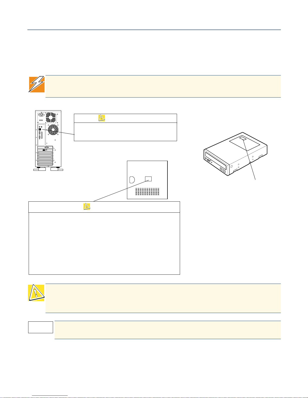
Location of the Required Label
Two caution labels are affixed Toshiba Magnia 550D server—one to the rear of the
server and the other on the inside of the side panel.
DANGER: Never remove the caution labels. If the labels are illegible, consult your
authorized service repair office or sales office.
CAUTION: This appliance contains a laser system and is classified as a “CLASS 1 LASER PRODUCT.” To use this
model properly , read the instruction manual carefully and k eep it f or y our future reference. In case of any trouble
with this model, please contact your nearest “AUTHORIZED service station.” To prevent direct e xposure to the laser
beam, do not try to open the enclosure.
Use of controls or adjustments or performance of procedures other than those specified in the owner’s
manual may result in hazardous radiation exposure.
DANGER: Power supply poses hazards of electrical
shock injury to persons and damage to equipment.
It should be removed and replaced only by trained
CAUTION
When you open the panel to work inside the server, observe the
precautions below:
1 Turn off the server and disconnect the power cable to prevent injury by
fans or an electric shock.
2 Disconnect cables inside the server carefully to prevent your hand from
hitting against the inside of the server and being injured.
3 Add or remove expansion cards carefully to prevent your hands from
being injured by their edges.
CAUTION
Inside of side panel
Caution label
CLASS 1 LASER PRODUCT
LASER KLASSE 1

6
Copyright
This guide is copyrighted by Toshiba America Information Systems, Inc. with all rights reserved. Under the copyright
laws, this guide cannot be reproduced in any form without the prior written permission of TAIS. No patent liability is
assumed, however, with respect to the use of the information contained herein.
©2002 by Toshiba America Information Systems, Inc. and/or Toshiba Corporation. All rights reserved.
Export Administration Regulation
This document contains technical data that may be controlled under the U.S. Export Administration Regulations, and
may be subject to the approval of the U .S . Department of Commerce prior to export. Any export, directly or indirectly, in
contravention of the U.S. Export Administration Regulations is prohibited.
Notice
The information contained in this manual, including but not limited to any product specifications, is subject to change
without notice.
TOSHIBA CORPORATION AND TOSHIBA AMERICA INFORMATION SYSTEMS, INC. (TOSHIBA) PROVIDE NO
WARRANTY WITH REGARD TO THIS MANUAL OR ANY OTHER INFORMATION CONTAINED HEREIN AND
HEREBY EXPRESSLY DISCLAIM ANY IMPLIED WARRANTIES OF MERCHANTABILITY OR FITNESS FOR ANY
PARTICULAR PURPOSE WITH REGARD TO ANY OF THE FOREGOING. TOSHIBA ASSUMES NO LIABILITY
FOR ANY DAMAGES INCURRED DIRECTLY OR INDIRECTLY FROM ANY TECHNICAL OR TYPOGRAPHICAL
ERRORS OR OMISSIONS CONTAINED HEREIN. IN NO EVENT SHALL TOSHIBA BE LIABLE FOR ANY
INCIDENTAL, CONSEQUENTIAL, SPECIAL, OR EXEMPLARY DAMAGES, WHETHER BASED ON TORT,
CONTRACT OR OTHERWISE, ARISING OUT OF OR IN CONNECTION WITH THIS MANUAL OR ANY OTHER
INFORMATION CONTAINED HEREIN OR THE USE THEREOF.
Trademarks
Magnia is registered trademark of Toshiba Corporation.
Adaptec and SCSISelect are registered trademar ks of Adaptec, Inc.
Intel and Pentium are registered trademarks of Intel Corporation.
OS/2 is a registered trademark, and PS/2 is a trademark of IBM Corporation.
MS-DOS and Windows are registered trademarks of Microsoft Corporation.
Ethernet and its logo are registered trademarks of Xerox, Inc.
VANTA is a registered trademark of nVIDIA Corporation.
Other product names and trademarks belong to the individual companies concerned.

7
Table of Contents
About this guide ............................................................................... 13
Safety icons............................................................................................... 14
Chapter 1: Getting Started ................................................................. 16
Make sure you have everything................................................................. 16
Environmental considerations................................................................... 16
System overview....................................................................................... 18
Fr ont of the server............................................................................ 18
Back of the server............................................................................ 22
Inside the server............................................................................... 23
Hard disk drive (HDD)............................................................................... 24
General maintenance................................................................................ 25
Care of the server ............................................................................ 25
Care of the mouse............................................................................ 25
Care of the keyboard........................................................................ 26
Keyboard comfort ...................................................................................... 26
Developing good work habits........................................................... 26
Arranging your work area................................................................. 27
Seating and posture......................................................................... 27
Using your arms and wrists.............................................................. 28
Chapter 2: Connecting Components.................................................. 29
Installing optional devices ......................................................................... 29
Before you start................................................................................ 29
Maintenance overview ..................................................................... 31
Removing and replacing the server panels............................................... 33
Removing the front door panel......................................................... 33
Replacing the front door panel......................................................... 34
Removing the side panel.................................................................. 35
Replacing the side panel.................................................................. 36
Adding a secondary CPU module............................................................. 37
Removing a CPU module................................................................. 41
Memory modules....................................................................................... 43

8
Installing a memory module............................................................. 45
Removing a memory module........................................................... 46
Adding an IDE hard disk drive................................................................... 47
Using System Setup after installing an IDE HDD...................................... 50
Adding a SCSI hard disk drive .................................................................. 51
SCSI configuration........................................................................... 51
Removing SCSI HDDs..................................................................... 55
RAID configuration........................................................................... 55
Adding SCSI I/O devices........................................................................... 55
SCSI ID............................................................................................ 56
Termination ...................................................................................... 56
Installing SCSI devices .................................................................... 56
Removing SCSI devices .................................................................. 57
Expansion cards........................................................................................ 58
IRQ setup......................................................................................... 58
Installing expansion cards................................................................ 59
Removing expansion cards.............................................................. 60
Connecting peripherals ............................................................................. 60
Connecting the power cable............................................................. 61
Turning on the server....................................................................... 62
Turning off the server....................................................................... 62
System startup .......................................................................................... 63
Starting up from the floppy disk drive............................................... 63
Starting from the HDD (must have an operating system installed).. 63
Starting from a bootable CD-ROM................................................... 63
Chapter 3: System Configuration Setup............................................. 64
Setup......................................................................................................... 64
Starting the Setup utility................................................................... 65
Operating procedures ...................................................................... 67
Setup items...................................................................................... 68
How to return to the Toshiba defaults........................................................ 82

9
Chapter 4: Hardware Diagnostics ...................................................... 84
Hardware Diagnostics Program................................................................. 84
Starting the Hardware Diagnostics Program.................................... 84
Hardware Diagnostics Program Main Menu..................................... 85
Diagnostics Test (01. DIAGNOSTIC TEST)..................................... 86
Running Test (02. RUNNING TEST)................................................ 87
Log Utilities..................................................................................... 100
Chapter 5: Server Setup Tool........................................................... 103
Starting SST............................................................................................ 103
Starting SST on another system.................................................... 104
Main Menu ..................................................................................... 105
RAID Configuration........................................................................ 106
Simplified RAID Configuration Setup............................................. 107
Operating System Installation........................................................ 108
Windows 2000 Quick Installation................................................... 109
Windows NT 4.0 Quick Installation ................................................ 120
Windows 2000 Manual Installation using SST............................... 132
Windows NT 4.0 Manual Installation using SST............................ 134
Windows 2000 / Windows NT 4.0 Manual Installation without SST 138
Post Installation (Windows 2000)................................................... 139
Post Installation (Windows NT 4.0)................................................ 140
NetWare Installation....................................................................... 141
NetWare 5.1 Post-Installation Procedure....................................... 144
Additional Software Manual Installations................................................. 144
HarnessEye/web............................................................................ 144
Toshiba Display Power Save Driver................................................ 145
AFT and ALB functions ........................................................................... 145
What are the AFT and ALB functions?........................................... 145
Setting up AFT and ALB functions................................................. 146
Troubleshooting....................................................................................... 146
Errors occurring during RAID creation........................................... 146
Error occurring during OS installation............................................ 149
Failure to create the System Partition............................................ 150

10
Errors occurring during FD reading................................................ 150
Errors occurring during SST startup .............................................. 151
Error occurring from incorrect operation ........................................ 151
Chapter 6: Management Software ................................................... 152
HEW modules ......................................................................................... 152
Module Roles................................................................................. 154
Security ................................................................................................... 154
Operating environment............................................................................ 155
Module Configuration Notes........................................................... 155
Management Console.................................................................... 155
Management Proxy........................................................................ 155
Agent.............................................................................................. 156
Before Installing Harness Eye/web.......................................................... 156
Installing HarnessEye/web...................................................................... 159
Removing HarnessEye/web.................................................................... 164
Using HarnessEye/web........................................................................... 165
Initial Screen .................................................................................. 165
Management Proxy Main screen ................................................... 166
Agent List screen ........................................................................... 167
Error Log ....................................................................................... 168
Agent tab........................................................................................ 169
Hardware Profile screen................................................................. 171
Software Profile.............................................................................. 172
Sensor Status................................................................................. 173
IDE RAID Status .......................... .................................................. 174
SCSI RAID Status screen.............................................................. 176
S.E.L. (System Event Log)............................................................. 178
Automatic Server Restart screen................................................... 183
Remote Power Control screen....................................................... 184
Fr ont Panel Indicators screen ........................................................ 185
Performance screen....................................................................... 187
Configure Alerts screen ................................................................. 189
Filter Settings tab........................................................................... 190

11
Advanced Setting tab..................................................................... 193
Agent Entry screen ........................................................................ 194
Data Base screen........................................................................... 196
Alert Delivery Configuration screen ............................................... 198
Agent Information Add/Delete Tool ......................................................... 203
Starting the tool.............................................................................. 203
Using the tool................................................................................. 203
Management Proxy Add/Delete Tool....................................................... 204
Starting the tool.............................................................................. 204
Using the Tool................................................................................ 204
Alert Message Function .......................................................................... 205
Starting the Function...................................................................... 205
Using the Function......................................................................... 205
Local Configuration Tool.......................................................................... 208
Starting the tool.............................................................................. 208
Using the tool................................................................................. 208
Remote Management.............................................................................. 210
Connection from the Guest............................................................ 212
Verifying Connection on the Guest Side ........................................ 212
Verifying Connection on the Host Side........................................... 212
Chapter 7: If Something Goes Wrong.............................................. 213
Troubleshooting....................................................................................... 213
Before calling for service................................................................ 214
Error check..................................................................................... 214
Initial startup................................................................................... 215
Application software problems....................................................... 215
Common problems......................................................................... 216
Before calling for service......................................................................... 217
Toshiba Technical Support ...................................................................... 217

12
Appendix A: Specifications............................................................... 218
Appendix B: Interfaces..................................................................... 224
Appendix C: Battery Replacement................................................... 230
Appendix D: Device Logs................................................................. 232
Appendix E: CMOS Setup................................................................ 236

13
Introduction
Congratulations on your purchase of the Toshiba Magnia 550D server. This server
combines high performance with great flexibility. Some of the many key features include:
❖ Dual Pentium
®
III processors (1.13GHz, 1.26GHz, 1.4GHz)
❖ 512 KB secondary cache
❖ High-speed ECC SDRAM memory expandable to 2 GB
❖ 48X-speed CD-ROM drive
❖ Five PCI bus slots (standard models have two slots occupied by a LAN card and a
SCSI card)
❖ 4X AGP bus slot (Occupied by a video card)
❖ Four 5.25-inch device bays (One bay occupied by a CD-ROM drive)
❖ Three 3.5-inch device bays (One bay occupied by a Floppy disk drive)
❖ Easy to install memory modules and expansion cards
About this guide
This user’s guide introduces the Toshiba Magnia 550D’s features and e xplains how to set
up, configure, and maintain the server.
Read through the guide to gain an overall understanding of operating procedures and
safety precautions before you use the Toshiba Magnia 550D server.

Safety icons 14
Safety icons
All safety instructions must be read carefully and fully understood, before attempting to
use your Toshiba Magnia 550D server.
This guide contains the safety instructions that must be observed in order to avoid
personal injury or damage to your server. The safety instructions have been classified
according to the seriousness of the risk, and the following icons highlight these
instructions as follows:
It is extremely important that basic safety practices are follo wed when installing and maintaining
the system.
Other icons used
Additional icons highlight other helpful or educational information:
DANGER: This icon indicates the e xistence of a hazard that could result in death or
serious bodily injury if the safety instruction is not observed.
CAUTION: This icon indicates the e xistence of a hazard that could result in damage
to equipment or property if the safety instruction is not observed.
WARNING: This icon indicates the existence of a hazard that could result in bodily
injury if the safety instruction is not observed.
NOTE: This icon indicates information that relates to the safe operation of the
equipment or related items.
TECHNICAL NOTE: This icon highlights technical information about the server.
HINT: This icon denotes helpful hints and tips.
DEFINITION: This icon indicates the definition of a term used in the text.

Safety icons 15
Other documentation
In addition to this user’s guide, Toshiba provides:
❖ Supplemental information and documentation provided on the Toshiba Magnia 550D
Server Setup Tool CD that shipped with the server. Refer to the Readme file on the
compact disc for a complete list of the documentation provided to support your
server.
Service options
Toshiba offers a full line of service options built around its warranty programs. See the
warranty material included with the server for registration information.
Maintenance contracts
Periodic maintenance and inspection is essential to k eep the server fully operational and
assure its safe use. Toshiba recommends purchasing a maintenance contract for this
purpose.
Getting Started Make sure you have everything 16
Chapter 1
Getting Started
This chapter describes the Toshiba Magnia 550D server and the environmental
conditions in which it is designed to operate.
Make sure you have everything
Unpack the boxes and check the contents against the Toshiba Magnia 550D Quick Start
card provided with your system.
If the server contains optional devices, those components are listed on the packing list
and your purchase order. If any items are missing or damaged, notify your Toshiba
representative immediately.
Environmental considerations
Place the server on a level surface in a clean, dust-free, and well-ventilated area free
from:
❖ Direct sunlight
❖ Vibration
❖ Liquids and corrosive chemicals
❖ Equipment that generates a strong electromagnetic field, such as large motors or
speaker phones
❖ Rapid changes in temperature or humidity and sources of temperature change such
as air conditioner vents, fans, or heaters
CAUTION: If you spill liquid into the server, turn it off, unplug it from the AC power
source, and let it dry out completely before turning it on again. If the server does not
operate correctly after you turn it back on, contact a Toshiba authorized service
provider.
Getting Started Environmental considerations 17
❖ Extreme heat, cold, or humidity. Use the server within the following range of ambient
conditions:
Temperature: 50° F to 95° F (10° C to 35° C)
Relative humidity: 30% to 80% RH (no condensation)
❖ If the server is exposed to conditions that could result in condensation accumulating
on the server’s cabinet or its internal components, wait one to two hours before
operating the server.
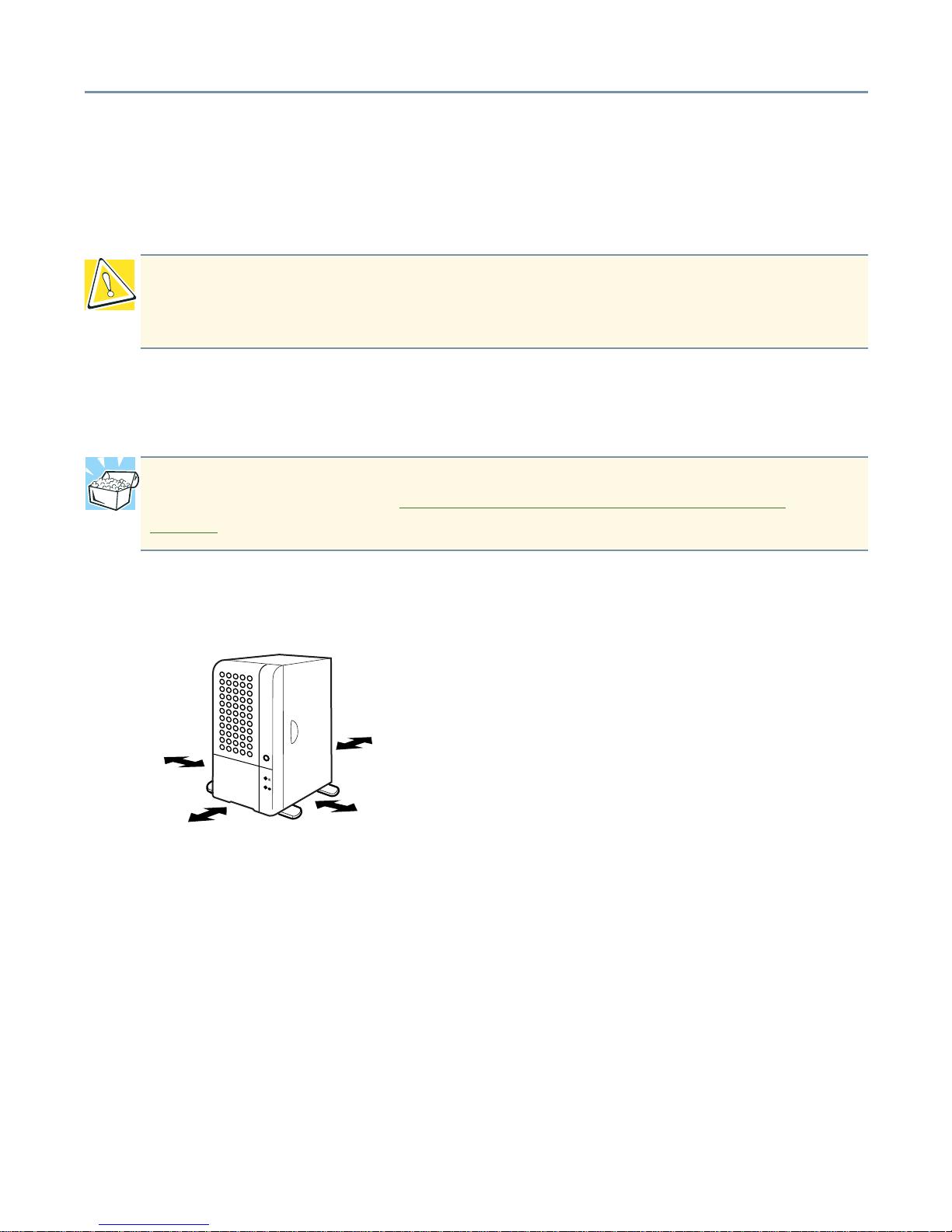
Allow sufficient space around the server and other equipment to allow for installation and
maintenance.
Minimum installation clearances
CAUTION: Condensation can corrode server components and short-circuit its
electrical circuits if the unit is on. Avoid exposing the server to condensation during
use and storage.
HINT: To inspect the server for moisture , remove the side panel. For instructions on
removing the side panel, see “Removing and replacing the server panels
” on
page 33.
2 inches (5cm)
8 inches
12 inches
2 inches
(5cm)
(30cm)
(20cm)
Getting Started System overview 18
System overview
The illustrations in this section identify the server’s major components, ports and
hardware.
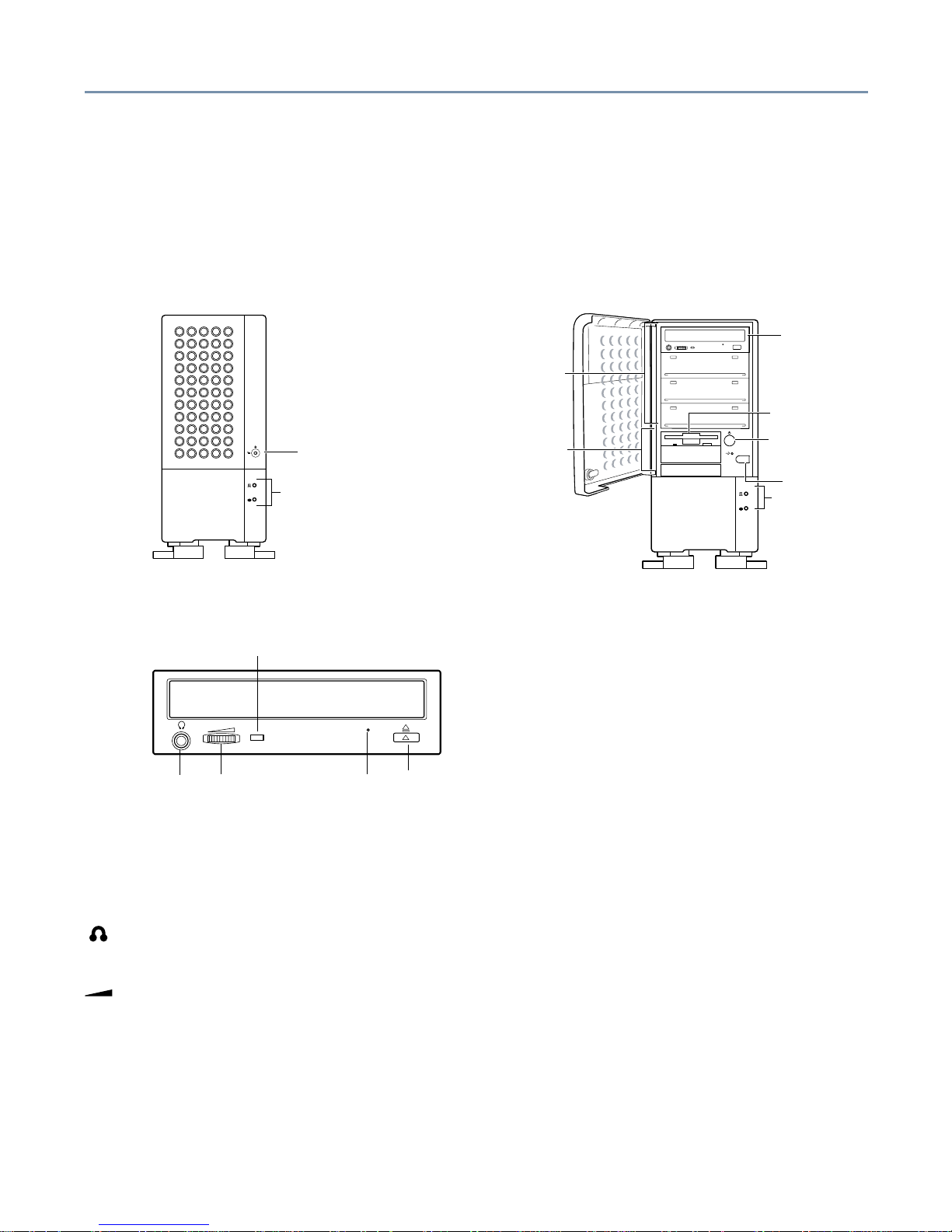
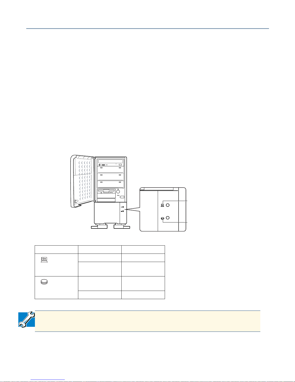
Front of the server
CD-ROM drive
The CD-ROM drive reads single-sided (3.15-in and 4.72-in) discs.
Disc tray - Holds compact discs in the CD-ROM drive.
Stereo headphone jack - Allows you to connect a headset or earphones to the CD-ROM
drive.
Volume control dial - Allows you to adjust the audio output volume of the CD-ROM drive.
Eject hole - Provides access to a manual eject button, allowing you to manually release
the disc tray if it does not open when you press the Stop/Eject button. To open the disc
tray manually, turn off the server and insert a slender object, such as a straightened
paper clip, into the pinhole.
Status light - Illuminates when the CD-ROM drive is in use.
System status
Floppy disk drive
Power button
Reset button
3.5" device bay
5.25" device bay
indicators
CD-ROM drive
Key lock
System status
indicators
Volume control
Eject button
Eject hole
Stereo
headphone
jack
CD-ROM drive
status indicator
Getting Started System overview 19
Stop/Eject button - Stops content playback. When content is not playing, pressing this
button either opens or closes the disc tray.
When handling compact discs:
❖ Hold the compact disc by the center and outer edge, taking care not to touch the
surface.
❖ Place the compact disc on the disc tray with the label side up.
❖ Keep the compact disc in its protective case when not in use.
❖ Avoid exposure to high temperature.
❖ Never bend or place heavy objects on the compact disc.
❖ If a compact disc is dirty, clean it carefully with a soft dry cloth. Always use gentle
strokes from the center of the disc outward. Never wipe in a circular motion.
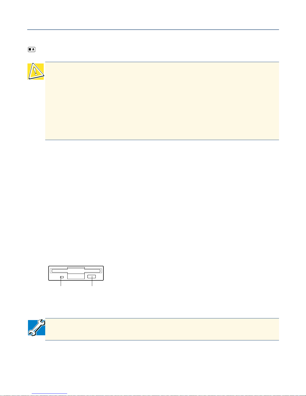
Floppy disk drive (FDD)
The drive reads 3.5-inch diskettes (1.44 MB/720 KB).
In-use light - Illuminates while the diskette is being accessed.
Eject button - Releases the diskette from the drive.
CAUTION: To avoid damaging the CD-ROM drive, never manually open the disc
tray while the server is on.
Neve r insert a pencil lead, plastic stick, or any other easily breakable object into the
manual eject button pinhole.
Never press the Stop/Eject button while the On/Busy light is lit. Doing so could
affect the system.
Never remove the compact disc from the CD-ROM drive when the On/Busy light is
lit.
TECHNICAL NOTE: To prevent data loss, never press the eject button while the inuse light is lit.
In-use light Eject button
Getting Started System overview 20
When handling diskettes:
❖ Never open the shutter.
❖ Avoid touching the diskette’s magnetic surface.
❖ Keep diskettes away from objects such as large motors or speaker phones that
generate strong magnetic fields. Magnetic fields may erase the data on the diskettes.
❖ Avoid exposing diskettes to direct sunlight or to any source of heat.
❖ Never place heavy objects on diskettes.
❖ Store diskettes under the following ambient conditions:
Temperature: 32° F to 127° F (0° C to 53°C)
Humidity: 8% to 90% RH
System indicator lights
Each system light provides information on the state of the server.
Type of light State of light State of server
Power Off Not running
Green Running
normally
Disk Off Disk not
running
Flashing green Disk running
TECHNICAL NOTE: Never turn off the server or reset the system while the disk
light is lit. Data could be lost or destroyed.
Power
Disk
indicator
indicator
Getting Started System overview 21
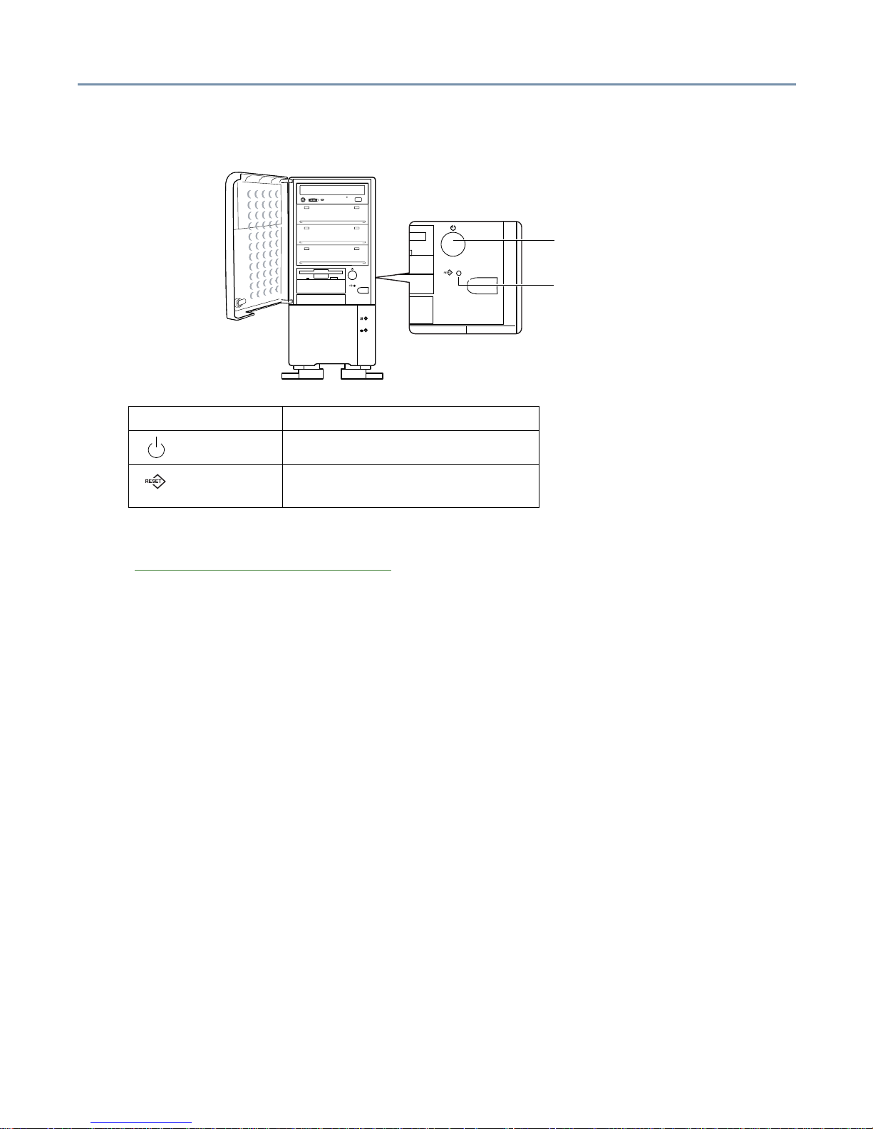
Operation buttons
The procedures for turning the server on and off vary depending on the system. See
“Turning on the server
” on page 62.
Feet
For better stabilization, f our feet are installed on the bottom of the server. To stabilize the
server, rotate the four feet out to their extended position.
Type of button Usage
Power Press to turn the server on or off.
Reset Press to restart the server. Use a
slender object to press the button.
Power button
Reset button
Getting Started System overview 22
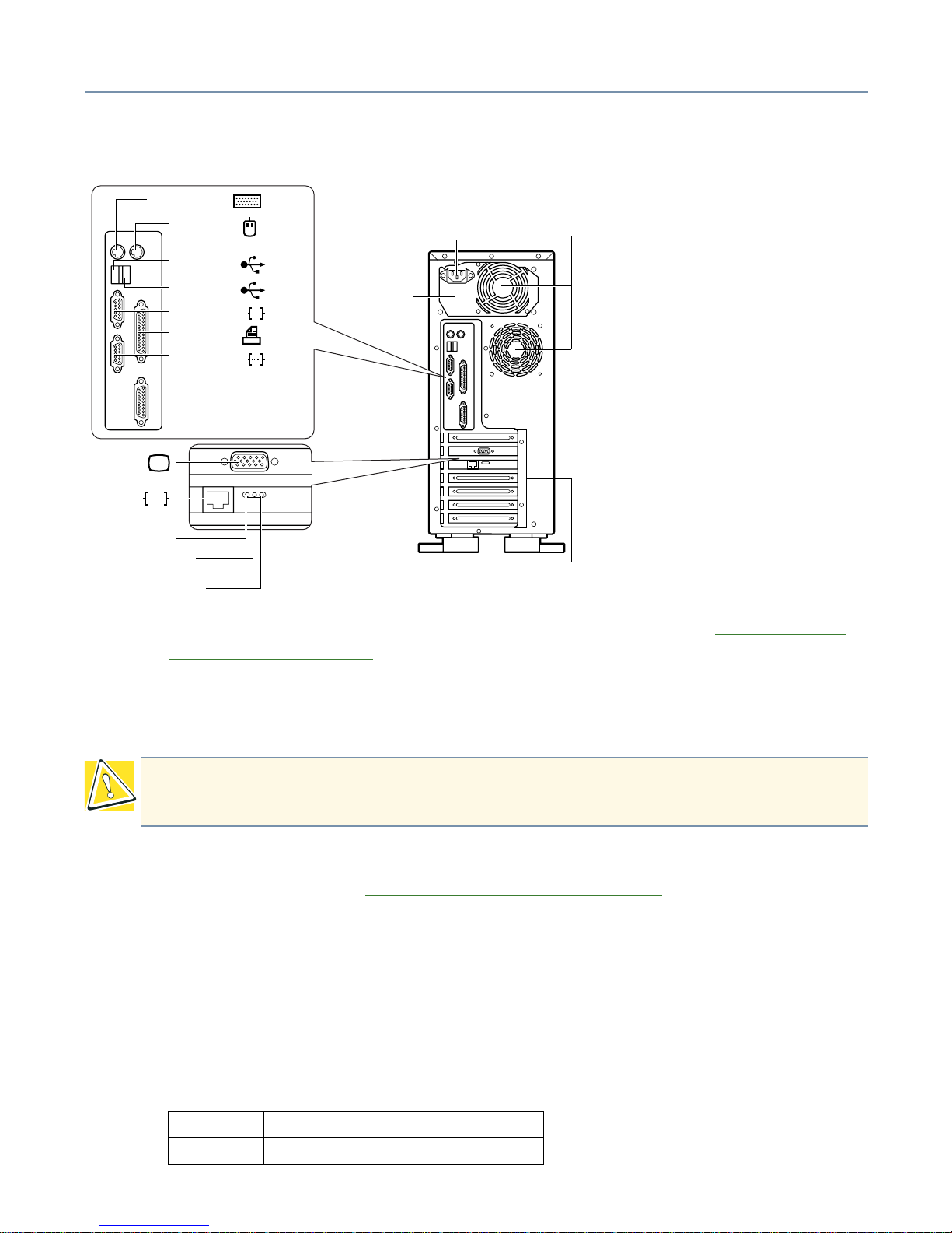
Back of the server
❖ AC connector - Use this port to connect the AC power cable. See “Connecting the
power cable” on page 61.
❖ Cooling fans - These f ans prev ent de vices in the server from ov erheating. The cooling
fans are not user-replaceable. If a cooling fan fails, contact your Toshiba authorized
service representative.
❖ I/O ports - Use these ports to connect the PS/2 keyboard, P/S mouse, printer, and
serial peripherals. See “C
onnecting peripherals” on page 60.
❖ USB ports - Use these ports to connect USB (Universal Serial Bus) devices (if
supported by your operating system).
❖ Monitor port - Use this port to connect the monitor.
❖ Ethernet port - This port allows you to connect to a 100BASE-TX or 10BASE-T
Ethernet
®
LAN (optional on some models).
❖ The Duplex light indicates the Duplex status.
CAUTION: To ensure proper ventilation and avoid overheating, keep the area
around the cooling fans clear.
On: Full Duplex connection is present
Off: Half Duplex is present
Serial port 2 ( )
Printer port ( )
USB port 2 ( )
Power supply unit
Serial port 1 ( )
Expansion slots
Video port ( )
LAN port ( )
Duplex indicator
LINK/ACT indicator
Link speed indicator
Mouse port ( )
Keyboard port ( )
USB port 1 ( )
Ether
AC power connector
Air vents
(FAN)
Getting Started System overview 23
❖ The Link Speed light (100M) indicates the communication speed.
❖ The LINK/ACT indicates the power and link status.
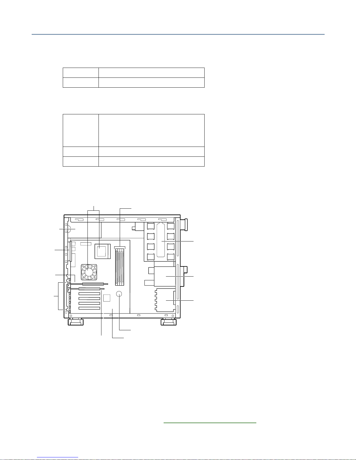
Inside the server
❖ Motherboard - The motherboard can accommodate up to two CPU modules and five
PCI expansion cards.
❖ 5.25-inch device ba ys - This device has four bays which are accessible from the front
of the server (one has a CD-ROM drive installed). The server supports built-in SCSI
devices.
❖ Memory slots - The server has four memory slots that support 64 MB, 128 MB, 256
MB, and 512 MB modules. See “Memory modules” on page 43 for more information.
On: Communication at 100 Mbps
Off: Communication at 10 Mbps
On: Po wer is being supplied to the card
and a good connection exists
between the card and the device it
is connected to
Off: Power is not being supplied
Flashing: Data is being sent or received
Internal battery
Expansion
Motherboard
CPU sockets
slots
5.25-inch
device bays
3.5-inch
device bays
Cooling fan
Cooling fan
Memory slots
Power supply
Video card
LAN card
(optional)
Getting Started Hard disk drive (HDD) 24
❖ 3.5-inch device bays - This device bay has two slots which are accessible from the
front of the server (one contains the floppy disk drive). In addition, the server has one
internal 3.5-inch device bay.
❖ Expansion slots - The system board has 6 expansion slots—one A GP and five 32-bit
PCI slots. The PCI slots accept PCI expansion cards and support PCI2.2
specifications.
Hard disk drive (HDD)
The disk light flashes green while the disk drive is reading or writing data. Refer to
“System indicator lights
” on page 20 for information on the disk activity indicators.
When the server is turned off, the hard disk drive head automatically retracts and
continues spinning. Wait 30 seconds for the drive head to stop spinning before removing
the hard disk drive.
CAUTION: Installing or replacing the HDD requires special skills and knowledge.
Toshiba recommends that instead of replacing the hard disk drive yourself, you
contact an authorized service provider to do it for you. While the system is running,
an error in the course of installing or replacing it could cause failures and
destruction or loss of important programs and data.
Avoid exposing the server to shock or vibration while the power is on. Even if the
light is off, the hard disk drive head stays in the data area while the disk is spinning.
Getting Started General maintenance 25
General maintenance
Care of the server
❖ If the server is dusty, wipe it clean with a soft, dry cloth. If it is very dirty, wipe it lightly
with a damp cloth.
❖ Avoid exposing the server to chemicals such as benzine, paint thinner and
insecticide, which could damage or discolor the case.
❖ To prevent system malfunctions, avoid exposing the server to shock or vibration.
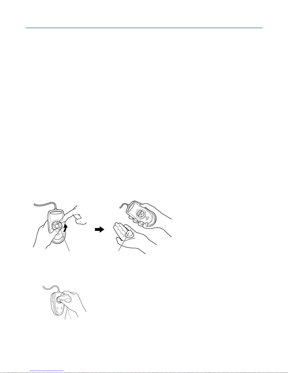
Care of the mouse
If the mouse is used for a long period of time, dust ma y adhere to the ball, making the
mouse pointer action sluggish or erratic.
Clean the mouse periodically:
1 Turn off the server.
2 Rotate the cover on the bottom of the mouse in the direction of the arrow
(counterclockwise), remove the cover, then remove the ball.
3 Using a dry cloth, remove any foreign matter adhering to the rollers inside the
mouse.
4 Wash the ball with tap water or a neutral detergent.
5 Dry the ball and place it back in the mouse.
BallBall retainer
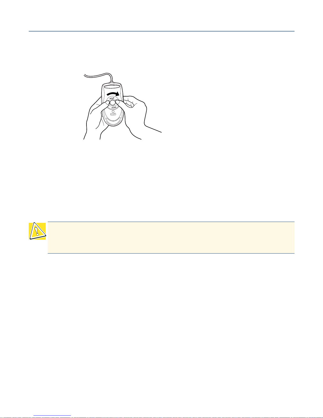
Getting Started Keyboard comf ort 26
6 Position the cover on the bottom of the mouse and rotate it in the opposite direction
to the arrows (clockwise) until it clicks into its locked position.
Care of the keyboard
If the keyboard is dusty, wipe it clean with a dry, soft cloth.
Keyboard comfort
You can work more comfortably and efficiently by thoughtfully organizing your work
space. Developing good work habits is the best way to avoid strain and stress to your
hands, back, neck and eyes.
Developing good work habits
The key to avoiding discomfort or injury from repetitive strain is to vary your activities. If
possible, schedule a v ariety of tasks into your working da y. Finding ways to break up the
routine can reduce stress and improve y our efficiency.
❖ Take recovery pauses from typing.
❖ Take short breaks to change position, stretch your muscles, and rest y our ey es . A two
or three minute break every half hour is more effective than one long break after
several hours.
❖ Stretch spontaneously throughout the day to reduce tension.
❖ Avoid performing repetitive activities for long periods. Intersperse repetitive activities
with other tasks.
❖ To reduce eye str ain, look away from the computer ev ery 15 minutes or so , and focus
your eyes on a distant object for 30 seconds.
CAUTION: Using the computer keyboard incorrectly may result in discomfort and
possible injury. If your hands, wrists, and/or arms bother you while typing, stop
using the computer and rest. If the discomfort persists, consult a physician.
Getting Started Keyboard comf ort 27
Arranging your work area
Carefully planned placement of your computer and desktop tools can help you avoid
stress-related injuries and make working more efficient. Adjusting the lighting can make it
easier to see your work and reduce eye strain.
❖ Place the keyboard on a flat surf ace, directly in front of y ou, at a comfortable distance.
When you use the keyboard, your arms and hands should be in a relaxed position
with your forearms parallel to the floor. You should be able to type without twisting
your body or neck.
❖ Place the monitor so that its top is at eye level (lower for bifocal or progressives
wearers).
❖ Adjust the screen to avoid reflections and glare.
❖ Set your paper holder at the same distance as the screen. If possible, adjust the
holder so that the paper is at the same height as the screen.
❖ Position the monitor so that sunlight or bright indoor lighting does not reflect off the
screen. Use tinted windows or shades to reduce glare.
❖ Av oid placing the monitor in front of a bright light that could shine directly in your ey es.
❖ If possible, use soft, indirect lighting in your computer work area.
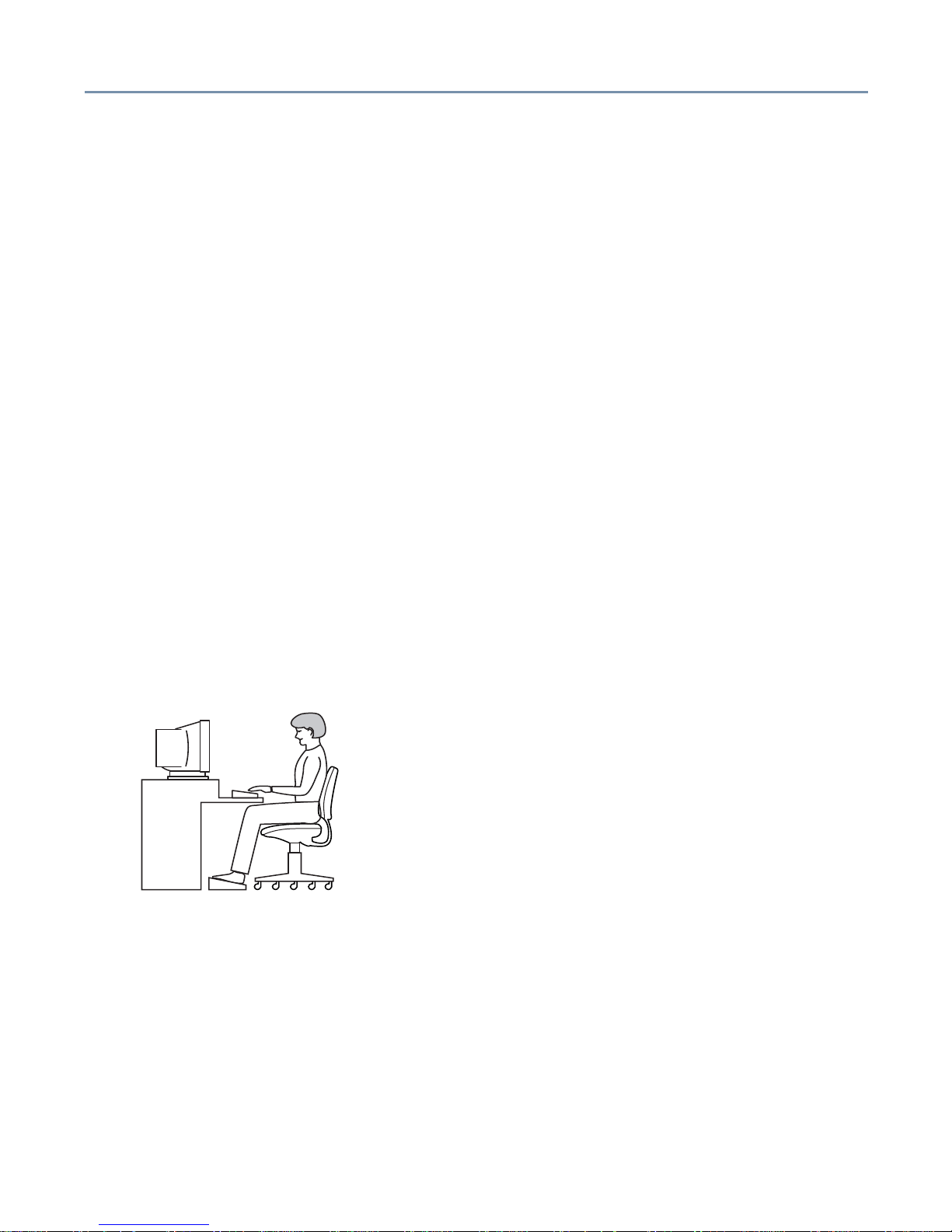
Seating and posture
Correct posture and computer placement
When using the computer, sit comfortably. Proper seating is one of the primary factors in
reducing work strain.
❖ Position your chair so that the keyboard is at or slightly below the level of your elbow.
You should be able to type comfortably with your shoulders relaxed.
❖ Your knees should be slightly higher than your hips. If necessary, use a foot rest to
raise the level of your knees and ease the pressure on the back of your thighs.
❖ Adjust the back of your chair so that it supports the lower curve of your spine. If
necessary, use a cushion to provide extra back support.

Getting Started Keyboard comf ort 28
❖ Sit with your back straight so that your knees, hips and elbows approximately form
90-degrees angles when you work. Do not slump forward or lean back too far.
Using your arms and wrists
❖ Keep your wrists straight while typing. If necessary, adjust the keyboard and chair
height to keep wrists straight.
❖ Avoid resting on your wrists while typing.
❖ Use a light touch on the keys and mouse.
❖ Avoid bending, arching, or twisting your wrists. Keep them in a relaxed, neutra l
position while typing.
❖ Exercise your hands, wrists and arms several times during the day to improve
circulation.
Regular attention to your work habits can make your time at the computer more
productive.
Connecting Components Installing optional devices 29
Chapter 2
Connecting Components
Installing optional devices
You should install all optional devices before setting up the server.
Before you start
❖ Before installing an optional device, read the manufacturer’s instructions and the
installation instructions in this manual.
❖ The procedures described in this chapter require specific technical knowledge and
experience. If you have no experience installing/removing optional devices, or if the
job seems difficult, consult your authorized service provider. Toshiba assumes no
liability for damages if you install and/or remove optional devices yourself.
DANGER: Never handle any electrical component that is not described in this
manual. Some parts carry high voltages and are dangerous.To avoid electrical
shock, shut down the server and disconnect the pow er cab le bef ore perf o rming any
server maintenance.
HINT: Toshiba recommends using Toshiba-certified devices or peripherals. Consult
your authorized service repair office, sales office, or log on to the Web site at
www.support.toshiba.com for recommended devices.
Connecting Components Installing optional devices 30
Selecting a workplace
❖ Before perf orming server maintenance, select a place that does not have high
humidity and is as free of dust and direct sunlight as possible.
❖ The ambient temperature and humidity should range between 50°F to 95°F (10°C to
35°C) and 30% to 80% RH. Avoid exposing the server to sharp temperature
fluctuations that could cause condensation.
❖ Nev er install or remove devices in a static-inducing environment (on a carpet, for
example). Electronic devices can fail if they are exposed to electrostatic discharge
(ESD).
Working safely
❖ Make sure you read and understand the instructions and precautions in this guide
before performing server maintenance.
❖ Perform the steps in each procedure in the order written.
❖ Before disconnecting any cables, check their positions to make sure you reconnect
them correctly.
❖ Check cable connectors for broken or bent pins. If a cable connector has screws,
tighten the screws finger-tight when securing the cable.
❖ If a failure occurs, consult your authorized service provider.
WARNING: To avoid electrical shock, neve r operate the server with the side panel
removed.
CAUTION: Internal server components can be seriously damaged by static
electricity . W ear a wrist or heel ground cable to discharge static electricity carried on
your body. If such equipment is not available, touch a grounded metal object to
discharge static electricity before working on sensitive electronic components.
Once you remove a device from its antistatic package, if necessary, place the
antistatic package and the device on a flat, grounded surface. Store the antistatic
package.
To prevent static build-up, never drag the server when moving it.
 Loading...