


2
®
Toshiba Magnia
3310/3310R User’s
Guide
Contacting Toshiba
If you need assistance:
❖ www.pcsupport.toshiba.com
Download the latest drivers, view detailed installation instructions, and access the
latest server information
❖ Toshiba Global Support Centre
Calling within the United States (800) 457-7777
Calling from outside the United States (949) 859-4273
For troubleshooting information, see If Something Goes Wrong on page 245.
TOSHIBA
SV149-0703M1
Model: Toshiba Magnia 3310/3310R
FCC Notice
This equipment has been tested and found to comply with the limits for a Class A digital device, pursuant to Part 15 of
the FCC Rules. These limits are designed to provide reasonable protection against harmful interference when the
equipment is operated in a commercial environment.
This equipment generates, uses, and can radiate radio frequency energy and, if not installed and used in accordance
with the instructions, may cause harmful interference to radio communications. Operation of this equipment in a
residential area is likely to cause interference, in which case the user will be required to correct the interference at his
own expense.
Only peripherals complying with the FCC Class A limits may be attached to this computer. Shielded
cables must be used between the external devices and the computer’s parallel port, PS/2
port, PS/2 mouse port, USB port, and monitor port. Changes or modifications made to this equipment
not expressly approved by Toshiba, or parties authorized by Toshiba, could void the user’s authority to
operate the equipment.
™
keyboard
3
This device complies with Part 15 of the FCC Rules. Operation is subject to the following two conditions:
❖ This device may not cause harmful interference in a commercial area.
❖ This device must accept any interference received, including interference that may cause undesired operation.
Contact: Toshiba America Information Systems, Inc.
9740 Irvine Blvd.
Irvine, CA 92618-1697
(949) 583-3000
EU-Declaration of Conformity
TOSHIBA
Toshiba declares that the product: Toshiba Magnia 3310/3310R (SYU3910W-00001, SYU3910W-00002, SYU3910W-00003, SYU3919W-R0001,
SYU3919W-R0002, SYU3919W-R0003, SYU3910W-000Z1, SYU3910W-000Z2, SYU3910W-000Z3, SYU3919W-R00Z1, SYU3919W-R00Z2,
SYU3919W-R00Z3) conforms to the following standards:
Toshiba erklärt, daß das Produkt: Toshiba Magnia 3310/3310R (SYU3910W-00001, SYU3910W-00002, SYU3910W-00003, SYU3919W-R0001,
SYU3919W-R0002, SYU3919W-R0003, SYU3910W-000Z1, SYU3910W-000Z2, SYU3910W-000Z3, SYU3919W-R00Z1, SYU3919W-R00Z2,
SYU3919W-R00Z3) folgenden Normen entspricht:
Toshiba déclarent que le produit cité ci-dessous: Toshiba Magnia 3310/3310R (SYU3910W-00001, SYU3910W-00002, SYU3910W-00003,
SYU3919W-R0001, SYU3919W-R0002, SYU3919W-R0003, SYU3910W-000Z1, SYU3910W-000Z2, SYU3910W-000Z3, SYU3919W-R00Z1,
SYU3919W-R00Z2, SYU3919W-R00Z3) est conformé aux normes suivantes:
Toshiba declaran que el producto: Toshiba Magnia 3310/3310R (SYU3910W-00001, SYU3910W-00002, SYU3910W-00003, SYU3919W-R0001,
SYU3919W-R0002, SYU3919W-R0003, SYU3910W-000Z1, SYU3910W-000Z2, SYU3910W-000Z3, SYU3919W-R00Z1, SYU3919W-R00Z2,
SYU3919W-R00Z3) cumple los siguientes estándares:
EU Declaration of Conformity
EU Übereinstimmungserklärung
Déclaration de conformité UE
Declaración de conformidad de la UE
Dichiarazione di conformità UE
EU Försäkran om Överensstämmelse
4
Toshiba dichiara, che il prodotto: Toshiba Magnia 3310/3310R (SYU3910W-00001, SYU3910W-00002, SYU3910W-00003, SYU3919W-R0001,
SYU3919W-R0002, SYU3919W-R0003, SYU3910W-000Z1, SYU3910W-000Z2, SYU3910W-000Z3, SYU3919W-R00Z1, SYU3919W-R00Z2,
SYU3919W-R00Z3) è conforme alle seguenti norme:
Toshiba intygar att produkten: Toshiba Toshiba Magnia 3310/3310R (SYU3910W-00001, SYU3910W-00002, SYU3910W-00003, SYU3919W-R0001,
SYU3919W-R0002, SYU3919W-R0003, SYU3910W-000Z1, SYU3910W-000Z2, SYU3910W-000Z3, SYU3919W-R00Z1, SYU3919W-R00Z2,
SYU3919W-R00Z3) överensstämmer med föijande normer:
Supplementary Information: “The product complies with the requirements of the Low Voltage Directive 73/23/EEC and the EMC
Directive 89/336/EEC.”
Weitere Informationen: “Das Produkt entspricht den Anforderungen der Niederspannungs-Richtlinie 73/23/EG und der EMC-
Richtlinie 89/336/EG.”
Informations complémentaires: “Ce produit est conforme aux exigences de la directive sur les basses tensions 73/23/CEE et de la
directive EMC 89/336/CEE.”
Información complementaria: “El Producto cumple los requisitos de baja tensión de la Directiva 73/23/CEE y la Directiva EMC 89/
336/CEE.”
Ulteriori informazioni: “Il prodotto é conforme ai requisiti della direttiva sulla bassa tensione 73/23/EG e la direttiva EMC 89/
336/EG.”
Ytteligare information: “Produkten uppfyller kraven enligt lägspänningsdirektiver 73/23/EEC och EMC-direktiv 89/336/EEC.”
EMC-emission: EN50081-1
EN55022
EN60555-2
EN61000-3-3
EMC-immunity: EN50082-1
EN61000-4-2
EN61000-4-3
ENV50204
EN61000-4-4
EN61000-4-5
EN61000-4-6
EN61000-4-11
Safety: EN60950
A1
A2
A3
A4
This product is carrying the CE-Mark in accordance with the related European Directives. Responsible for CE-Marking
is Toshiba Europe, Hammfeldamm 8, 41460 Neuss, Germany.
1992
1994
1987
1995
1997
1995
1998
1995
1995
1995
1996
1994
1992
1993
1993
1993
1995
1997
CD:8kV, AD:15kV
10V/m, 80-1000MHz, 1kHz 80% AM
10V/m, 895-905MHz, 200Hz 50% PM
AC-line: 2kV, Signal-line: 1kV, f: 5kHz, Polarity:+/AC-line: 1kV / 2kV, Polarity; +/10V emf, 0.15-80MHz, 80% AM
30% 10ms, 60% 100ms, >95% 5000ms
Notice to user of EN55022
This is a Class A product. In a domestic environment this product may cause radio interference in which
case the user may be required to take adequate measures.
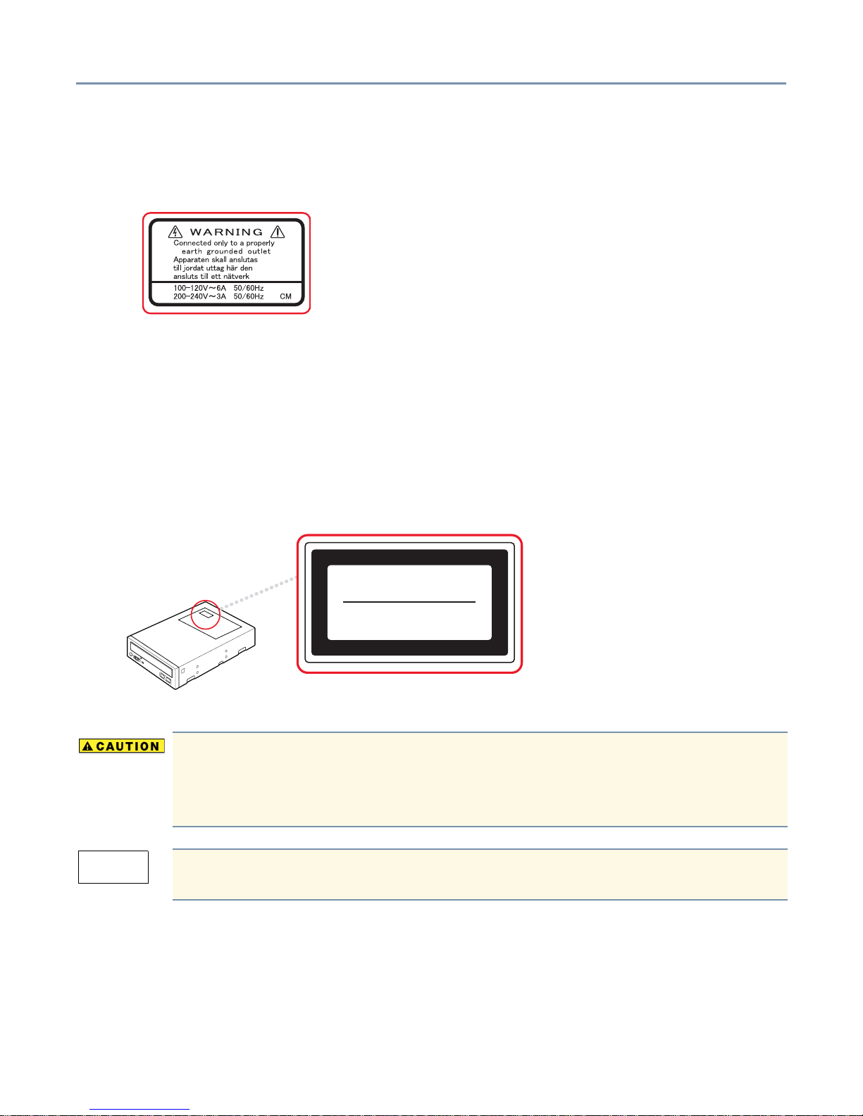
Warning Labels
Warning labels are attached to various components. Read these labels carefully.
CD-ROM Safety Instruction
The CD-ROM drive employs a laser system. To ensure proper use of this product, please read the CD-ROM instruction
manual carefully and retain for future reference. Should the unit ever require maintenance, contact an authorized
service location. Use of controls, adjustments or performance of procedures other than those specified may result in
hazardous radiation exposure. To prevent direct exposure to the laser beam, do not try to open the enclosure.
5
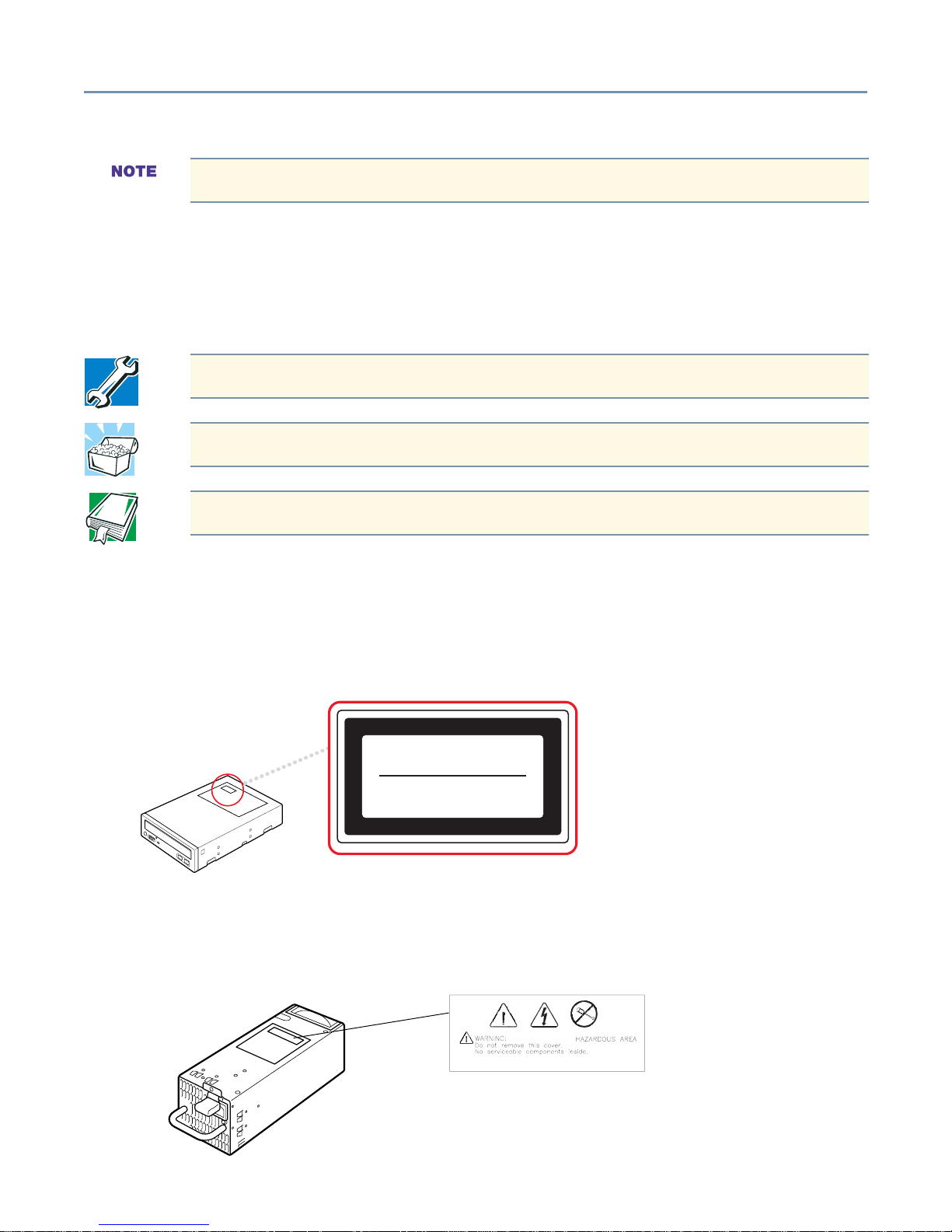
Location of the required label
CLASS 1 LASER
PRODUCT TO IEC 60825-1
LASER KLASSE 1
N
ACH IEC 60825-1
This appliance contains a laser system and is classified as a “CLASS 1 LASER PRODUCT.” To use this
model properly, read the instruction manual carefully and keep it for your future reference. In case of any
trouble with this model, please contact your nearest authorized service provider. To prevent direct exposure
to the laser beam, do not try to open the enclosure.
CLASS 1 LASER PRODUCT
LASER KLASSE 1
Use of controls or adjustments or performance of procedures other than those specified in the owner’s
manual may result in hazardous radiation exposure.
Copyright
This guide is copyrighted by Toshiba America Information Systems, Inc. with all rights reserved. Under the copyright
laws, this guide cannot be reproduced in any form without the prior written permission of Toshiba. No patent liability is
assumed, however, with respect to the use of the information contained herein.
©2003 by Toshiba America Information Systems, Inc. All rights reserved.

Export Administration Regulation
This document contains technical data that may be controlled under the U.S. Export Administration Regulations, and
may be subject to the approval of the U.S. Department of Commerce prior to export. Any export, directly or indirectly, in
contravention of the U.S. Export Administration Regulations is prohibited.
Disclaimer
The information contained in this manual, including but not limited to any instructions, descriptions and product
specifications, is subject to change without notice.
TOSHIBA CORPORATION AND TOSHIBA AMERICA INFORMATION SYSTEMS, INC. (TOSHIBA) PROVIDE NO
WARRANTY WITH REGARD TO THIS MANUAL OR ANY OTHER INFORMATION CONTAINED HEREIN AND
HEREBY EXPRESSLY DISCLAIM ANY IMPLIED WARRANTIES OF MERCHANTABILITY OR FITNESS FOR ANY
PARTICULAR PURPOSE WITH REGARD TO ANY OF THE FOREGOING. TOSHIBA ASSUMES NO LIABILITY
FOR ANY DAMAGES INCURRED DIRECTLY OR INDIRECTLY FROM ANY TECHNICAL OR TYPOGRAPHICAL
ERRORS OR OMISSIONS CONTAINED HEREIN. IN NO EVENT SHALL TOSHIBA BE LIABLE FOR ANY
INCIDENTAL, CONSEQUENTIAL, SPECIAL, OR EXEMPLARY DAMAGES, WHETHER BASED ON TORT,
CONTRACT OR OTHERWISE, ARISING OUT OF OR IN CONNECTION WITH THIS MANUAL OR ANY OTHER
INFORMATION CONTAINED HEREIN OR THE USE THEREOF.
6
Some states do not allow the exclusion of incidental or consequential damages so the above limitation or exclusion
may not apply to you.
Trademarks
Magnia is a registered trademark and InTouch is a registered trademark of Toshiba America Information Systems, Inc.
Intel, Pentium, LANDesk, and Xeon are registered trademarks of Intel Corporation.
Wake-on-Lan is a registered trademark and PS/2 is a trademark of International Business Machines Corporation.
Microsoft, its logos, MS-DOS, Windows, Windows XP, Windows 2000, and MS are registered trademarks of Microsoft
Corporation.
Ethernet is a registered trademark of Xerox, Inc.
NetWare is a registered trademark of Novell Corporation.
MegaRAID is a registered trademark of LSI Logic, Inc.
SCSISelect is a registered trademark of Adaptec, Inc.
Other product names and trademarks belong to the individual companies concerned.

Table of Contents
About this guide......................................................................................... 14
Other documentation................................................................................. 15
Safety icons............................................................................................... 15
Other icons used.............................................................................. 16
Warning, danger and caution labels.......................................................... 16
EPS-R cage Warning and Danger labels......................................... 16
Service options.......................................................................................... 17
Maintenance contracts .............................................................................. 17
Cleaning the server ................................................................................... 17
Setting up your work environment............................................................. 17
Developing good work habits ........................................................... 18
7
Arranging your work area................................................................. 18
Seating and posture......................................................................... 19
Using your arms and wrists.............................................................. 19
Chapter 1: Getting Started ................................................................. 20
Make sure you have everything................................................................. 20
Installing optional internal devices............................................................. 20
Environmental considerations ................................................................... 20
General environmental considerations............................................. 20
Power requirements .................................................................................. 23
Front of the server..................................................................................... 23
Limiting access to server controls.................................................... 24
Server controls, indicators and drives.............................................. 25
Removing and replacing the server panels............................................... 30
Removing the side panel (pedestal model)...................................... 30
Replacing the side panel (pedestal model)...................................... 31
Removing the top panel (rack models) ............................................ 31
Replacing the top panel (rack models)............................................. 32
Rear view of the server ............................................................................. 33
Power supply unit ............................................................................. 33
Isolating EPS-R cage and cooling fan unit failures.................................... 34
Indication of a failure........................................................................ 35

8
Identifying the AC power connector and I/O signal ports................. 37
Expansion slots................................................................................ 38
Connecting peripheral devices.................................................................. 39
Connecting AC power................................................................................ 40
Inside the server........................................................................................ 41
Motherboard..................................................................................... 41
Cooling fans ..................................................................................... 41
CPU sockets .................................................................................... 42
Internal battery................................................................................. 42
Memory bank ................................................................................... 42
Expansion slots................................................................................ 42
Turning on the server ................................................................................ 42
Using Wake-On-LAN® ..................................................................... 43
Power On Self Test (POST)....................................................................... 44
Booting the server ..................................................................................... 44
Starting the server from the floppy disk drive................................... 44
Starting the server from the hard disk drive ..................................... 45
Starting the server from the CD-ROM drive ..................................... 45
BIOS setup................................................................................................ 46
Setting the system configuration ............................................................... 46
BIOS Setup Utility ............................................................................ 46
Onboard SCSI Utility........................................................................ 46
Turning off the server ................................................................................ 46
Performing a normal shutdown ........................................................ 46
Performing an abnormal system shutdown...................................... 47
Chapter 2: Connecting Hardware Devices ......................................... 48
Installing optional devices ......................................................................... 48
Before you start................................................................................ 48
Maintenance overview............................................................................... 50
Working on rack-mounted servers ................................................... 51
Cooling fans ............................................................................................. 53
Removing and installing an intake fan.............................................. 53
Removing and replacing a primary or redundant exhaust fan ......... 56
Memory modules....................................................................................... 60

9
Installing memory modules .............................................................. 61
Removing a memory module ........................................................... 66
CPU module.............................................................................................. 69
Before Installing and Removing a CPU module............................... 70
Replacing the Retention Clamp ....................................................... 71
Removing the CPU Module.............................................................. 72
Installing the CPU Module................................................................ 76
Post-Procedure After Installing/Removing the CPU Module ............ 82
Internal battery .......................................................................................... 84
Replacing the internal battery .......................................................... 84
SCSI devices............................................................................................. 86
Assigning SCSI IDs.......................................................................... 86
Detecting SCSI Devices (SAF-TE)................................................... 86
Terminating SCSI devices................................................................ 87
Removing device bay spacers ......................................................... 87
Installing SCSI devices .................................................................... 88
Removing SCSI devices .................................................................. 90
Hard disk drives (HDDs)............................................................................ 91
Downgraded server operation.......................................................... 91
RAID failures.................................................................................... 93
Installing a hard disk drive......................................................................... 93
Replacing a hard disk drive.............................................................. 95
Expansion cards........................................................................................ 97
Restrictions on PCI expansion cards ............................................... 98
Setting IRQ levels............................................................................. 98
Cautions when adding RAID controllers and SCSI host adapters ... 98
Installing expansion cards................................................................ 98
Removing expansion cards............................................................ 100
Installing a RAID controller............................................................. 101
Power supply units .................................................................................. 103
EPS-R power supply units ............................................................. 103
Chapter 3: System Configuration Setup........................................... 106
BIOS Setup Utility.................................................................................... 106
Starting the BIOS Setup Utility....................................................... 106

10
Changing the BIOS settings........................................................... 108
BIOS settings ................................................................................. 108
Onboard SCSI Utility ............................................................................... 114
Starting the SCSI Utility ................................................................. 114
Menu configuration......................................................................... 115
SCSI Utility keyboard commands................................................... 115
Setting devices............................................................................... 116
Installing the RAID Utility......................................................................... 118
Automatic rebuilding with a hot spare ............................................ 118
Rebuilding the disk array using Power Console Plus..................... 118
Additional options for MegaRAID BIOS setup................................ 119
Chapter 4: Server Setup Tool........................................................... 120
Starting SST............................................................................................ 120
Starting SST on another system .................................................... 122
Main Menu ..................................................................................... 122
RAID Configuration ........................................................................ 123
Simplified RAID Configuration Setup ............................................. 124
Operating System Installation ........................................................ 125
Windows 2003 Quick Installation ................................................... 126
Windows 2000 Quick Installation ................................................... 139
Windows 2003 Manual Installation using SST............................... 154
Windows 2000 Manual Installation using SST............................... 156
Windows 2003/2000 Manual Installation without SST ................... 158
Post Installation (Windows Server 2003) ....................................... 159
Post Installation (Windows 2000) ................................................... 160
Additional Software Manual Installations ....................................... 160
HarnessEye/web............................................................................ 161
Toshiba Display Power Save Driver................................................ 161
Troubleshooting....................................................................................... 162
Errors occurring during RAID creation ........................................... 162
Error occurring during OS installation ............................................ 164
Failure to create the System Partition ............................................ 165
Errors occurring during FD reading................................................ 165

11
Errors occurring during SST startup .............................................. 166
Error occurring from incorrect operation ........................................ 166
Chapter 5: Management Software ................................................... 167
HEW modules ......................................................................................... 167
Module Roles ................................................................................. 169
Security ................................................................................................... 170
Operating environment............................................................................ 170
Module Configuration Notes........................................................... 170
Management Console.................................................................... 171
Management Proxy........................................................................ 171
Agent.............................................................................................. 171
Before Installing Harness Eye/web.......................................................... 172
Installing HarnessEye/web...................................................................... 174
Removing HarnessEye/web.................................................................... 180
Using HarnessEye/web........................................................................... 181
Initial Screen .................................................................................. 181
Agent List screen ........................................................................... 183
Remote Console screen................................................................. 184
Main Summary screen ................................................................... 185
Details screen ................................................................................ 187
Product Information screen............................................................ 189
Sensor Status screen..................................................................... 190
IDE RAID Status screen................................................................. 192
SCSI RAID Status screen .............................................................. 194
Mobile IP Software screen ............................................................. 196
Software Access Point screen........................................................ 200
Error Log ....................................................................................... 201
Remote Power Control screen ....................................................... 202
Configure Alerts screen ................................................................. 204
Filter Settings tab ........................................................................... 205
S.E.L. (System Event Log)............................................................. 209
Performance Settings screen ......................................................... 215
Performance screen ....................................................................... 217

12
LAN Alerting Configuration screen................................................. 218
Configuration screen...................................................................... 219
Front Panel Indicators screen ........................................................ 220
Collect Logs screen........................................................................ 221
Advanced Settings .................................................................................. 223
Agent Entry screen ........................................................................ 223
DB Backup screen ......................................................................... 225
Cleanup Error Log screen.............................................................. 226
Alert Message Location screen...................................................... 227
Alert Message Contents screen..................................................... 229
Email Address screen .................................................................... 230
Email Contents screen................................................................... 231
Screen Settings screen.................................................................. 232
Agent Information Add/Delete Tool ......................................................... 234
Starting the tool.............................................................................. 234
Using the tool ................................................................................. 234
Management Proxy Add/Delete Tool ....................................................... 235
Starting the tool.............................................................................. 235
Using the Tool ................................................................................ 235
Alert Message Function .......................................................................... 236
Starting the Function...................................................................... 236
Using the Function ......................................................................... 236
Local Configuration Tool.......................................................................... 239
Starting the tool.............................................................................. 239
Using the tool ................................................................................. 239
Remote Management.............................................................................. 242
Connection from the Guest ............................................................ 243
Verifying Connection on the Guest Side ........................................ 244
Verifying Connection on the Host Side........................................... 244
Chapter 6: If Something Goes Wrong .............................................. 245
Identifying the problem............................................................................ 245
Startup sequence .................................................................................... 246
Error checking................................................................................ 246
Startup problems............................................................................ 247

13
Application software problems................................................................. 247
Common hardware problems.................................................................. 248
The front panel power indicator light is not on ............................... 248
The screen is blank........................................................................ 248
Characters are distorted or do not display properly ....................... 248
The FDD indicator light is not on.................................................... 249
The HDD status indicator lights are not on .................................... 249
The hard disk drive does not respond............................................ 249
The FDD indicator does not light.................................................... 249
An error is displayed during POST operation, or POST stops midway .
249
Loading of RAID controller BIOS stops midway............................. 250
Cannot install the OS ..................................................................... 250
The OS does not boot, or the OS bootup stops midway................ 251
Windows 2000 is locked or cannot be used................................... 251
The power button does not function after a system abort.............. 251
Remedy when Windows 2000 is Usable................................................. 252
Remedy when Windows 2000 is Unusable............................................. 252
Abnormal system shutdown .................................................................... 253
Before calling for service ......................................................................... 253
Toshiba Technical Support ...................................................................... 253
Chapter 7: Hardware Diagnostics .................................................... 254
HW Diagnostics Program Main Menu ..................................................... 255
Diagnostics Test (01. DIAGNOSTIC TEST) ................................... 256
Running Test (02. RUNNING TEST) .............................................. 258
Log Utilities..................................................................................... 270
Appendix A: Specifications............................................................... 274
Appendix B: Interface....................................................................... 280
Appendix C: Jumper Settings........................................................... 289
Appendix D: Sensor List................................................................... 291
Appendix E: Unit Logs...................................................................... 294

14
Introduction
Thank you for purchasing the Toshiba Magnia 3310/3310R server, which combines high
performance with great flexibility.
❖ Supports up to two Intel
❖ 512 KB secondary cache
❖ PC2100 DDR 200 MHz high-speed ECC memory, expandable to 6 GB
❖ 48x speed IDE CD-ROM drive
❖ Server drivers and other important tools
❖ Two network ports: one 1000/100/10Base-TX and one 100Base-TX/10BaseT
❖ Integrated network adapter that supports Wake-on-LAN®, Automatic Load Balancing
(ALB) and Automatic Fault Tolerance (AFT) functions
❖ Pedestal models quickly and easily convert to 5U rack mount with a rack-mount kit
❖ Supports up to six (146 GB) SCSI hot-swappable, RAID-ready, SCA drives
❖ Single channel, 64-bit Ultra 320 SCSI PCI RAID controller option
❖ Three 5.25-inch device bays (one occupied by the CD-ROM drive)
❖ Redundant power supply capable
❖ Easy-to-upgrade memory modules and expansion cards, no tools needed
®
Xeon™ processors - 2.40 GHz or 3.06 GHz
❖ Split-front panel providing three levels of physical security
About this guide
This guide introduces the features of the Toshiba Magnia 3310/3310R server and
explains how to set up, configure, and maintain the server. Before using your Toshiba
server, refer to this guide to gain an overall understanding of operating procedures and
safety precautions.
Other documentation
In addition to this user’s guide, the Toshiba Magnia 3310/3310R Server Setup Tool CD
contains:
❖ The Safety Instruction Guide for Toshiba Servers, which contains general safety
information.
❖ Other related documentation.
Check the readme.txt file for a complete list of the documentation provided on the
Magnia 3310/3310R Server Setup Tool CD.
Toshiba also provides you with:
❖ A Toshiba Magnia® 3310/3310R Quick Start Card, which identifies the major server
components, and provides a quick reference on connection, setup, and system
configuration information.
❖ Warranty information
Other documentation 15
Safety icons
All safety instructions must be read carefully and fully understood, before attempting to
use your Toshiba Magnia® 3310/3310R server.
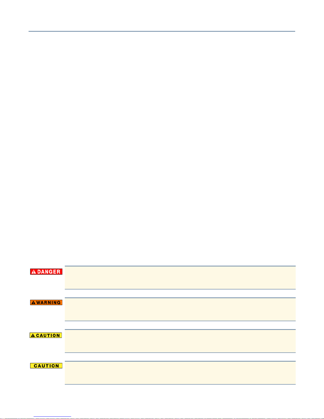
This guide contains the safety instructions that must be observed in order to avoid
personal injury or damage to your server. The safety instructions have been classified
according to the seriousness of the risk, and the following icons highlight these
instructions as follows:
Indicates an imminently hazardous situation which, if not avoided, will result in
death or serious injury.
Indicates a potentially hazardous situation which, if not avoided, could result in
death or serious injury.
Indicates a potentially hazardous situation which, if not avoided, may result in
minor or moderate injury.
Indicates a potentially hazardous situation which, if not avoided, may result in
property damage.
Provides important information.
It is extremely important that basic safety practices are followed when installing and
maintaining the system.
Other icons used
Additional icons highlight other helpful or educational information:
TECHNICAL NOTE: This icon highlights technical information about the server.
HINT: This icon denotes helpful hints and tips.
DEFINITION: This icon indicates the definition of a term used in the text.
Warning, danger and caution labels 16
Warning, danger and caution labels
CD-ROM caution label
CLASS 1 LASER
PRODUCT TO IEC 60825-1
LASER KLASSE 1
N
ACH IEC 60825-1
EPS-R cage Warning and Danger labels
A warning label is attached to the power supply units of this equipment, as shown below:
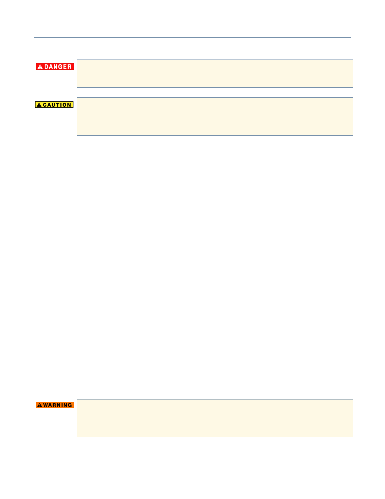
Never remove the caution labels. If the labels are illegible, consult your authorized
service repair office or sales office.
Never use the handle of the EPS-R power supply unit to lift or move the server.
Using the handle in this manner can cause severe damage to the power supply,
the EPS-R cage, and/or internal server components.
Service options
Toshiba offers a full line of service options built around its warranty programs. Refer to
the warranty and service material included with the server for registration information, or
visit our web site at www.support.toshiba.com.
Maintenance contracts
Service options 17
Periodic maintenance and inspection is essential to keeping the server fully operational
and assuring its safe use. Toshiba recommends obtaining a maintenance contract with
an authorized Toshiba Magnia service provider. For more information, use the following
Toshiba Global Support Centre numbers:
Calling within the United States (800) 457-7777
Calling from outside the United States (949) 859-4273
Cleaning the server
If the server’s exterior case is dirty or stained, clean it with a soft cloth. If necessary,
moisten the cloth with water. Never use harsh chemicals to clean the server.
Setting up your work environment
You can work more comfortably and efficiently by thoughtfully organizing your work
space. Developing good work habits is the best way to avoid strain and stress to your
hands, back, neck and eyes.
Using the computer keyboard incorrectly may result in discomfort and possible
injury. If your hands, wrists, and/or arms bother you while typing, stop using the
computer and rest. If the discomfort persists, consult a physician.

Developing good work habits
The key to avoiding discomfort or injury from repetitive strain is to vary your activities. If
possible, schedule a variety of tasks into your working day. Finding ways to break up the
routine can reduce stress and improve your efficiency.
❖ Take short breaks from typing.
❖ Take short breaks to change position, stretch your muscles, and rest your eyes. A two
or three minute break every half hour is more effective than one long break after
several hours.
❖ Stretch spontaneously throughout the day to reduce tension.
❖ Avoid performing repetitive activities for long periods. Intersperse repetitive activities
with other tasks.
❖ To reduce eye strain, look away from the computer every 15 minutes or so, and focus
your eyes on a distant object for 30 seconds.
Setting up your work environment 18
Arranging your work area
Carefully planned placement of your computer and desktop tools can help you avoid
stress-related injuries and make working more efficient. Adjusting the lighting can make it
easier to see your work and reduce eye strain.
❖ Place the keyboard on a flat surface, directly in front of you, at a comfortable distance.
When you use the keyboard, your arms and hands should be in a relaxed position
with your forearms parallel to the floor. You should be able to type without twisting
your body or neck.
❖ Place the monitor so that its top is at eye level. If you wear bifocal or progressive
lenses, position the monitor slightly lower.
❖ Adjust the screen to avoid reflections and glare.
❖ Set your paper holder at the same distance as the screen. If possible, adjust the
holder so that the paper is at the same height as the screen.
❖ Position the monitor so that sunlight or bright indoor lighting does not reflect off the
screen. Use tinted windows or shades to reduce glare.
❖ Avoid placing the monitor in front of a bright light that could shine directly in your eyes.
❖ If possible, use soft, indirect lighting in your computer work area.
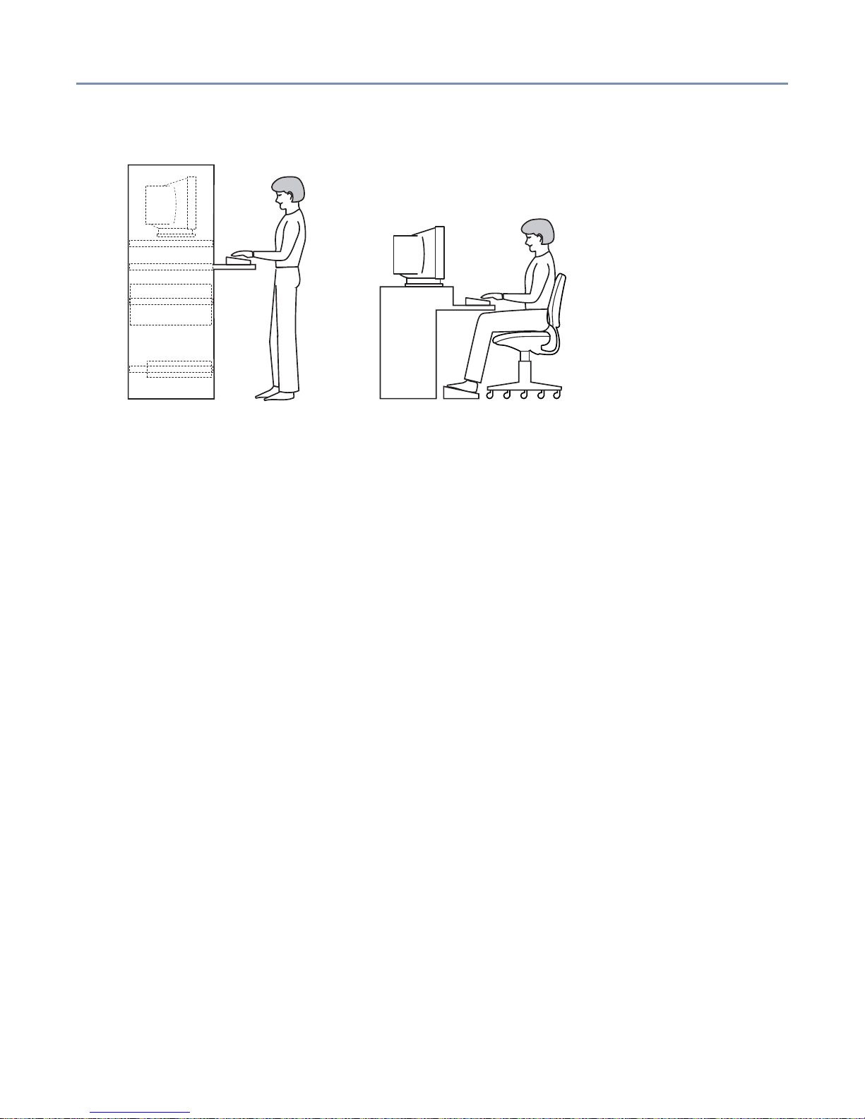
Seating and posture
Correct posture and computer placement
When using the computer, sit comfortably. Proper seating is a primary factor in reducing
strain.
Setting up your work environment 19
❖ Position your chair so that the keyboard is at or slightly below the level of your elbow.
You should be able to type comfortably with your shoulders relaxed.
❖ Your knees should be slightly higher than your hips. If necessary, use a footrest to
raise the level of your knees and ease the pressure on the back of your thighs.
❖ Adjust the back of your chair so that it supports the lower curve of your spine. If
necessary, use a cushion to provide extra back support.
❖ Sit with your back straight so that your knees, hips and elbows form approximately
90-degree angles when you work. Do not slump forward or lean back too far.
Using your arms and wrists
❖ Keep your wrists straight while typing. If necessary, adjust the keyboard and chair
height to keep wrists straight.
❖ Avoid resting on your wrists while typing.
❖ Use a light touch on the keys and mouse.
❖ Avoid bending, arching, or twisting your wrists. Keep them in a relaxed, neutral
position while typing.
❖ Exercise your hands, wrists and arms several times during the day to improve
circulation.
Regular attention to your work habits can make your time at the computer more
productive.
20
Chapter 1
Getting Started
This chapter provides a detailed description of the server and the environmental
conditions in which it is designed to operate.
Handling the cord on this product will expose you to lead, a chemical known to the
State of California to cause birth defects or other reproductive harm. Wash your
hands after handling.
Make sure you have everything
Unpack the boxes and check the contents against your purchase order. If the server
contains optional devices, those components will also be listed. If any items are missing
or damaged, notify your sales representative immediately.
Installing optional internal devices
Install all optional devices before setting up the server. The installation and configuration
procedures described in this guide require specific technical knowledge and experience.
If you have no experience installing and removing computer hardware devices, or if the
job seems difficult, consult an authorized Toshiba Magnia service provider. Toshiba
assumes no liability for damages if you install and remove optional devices yourself.
Environmental considerations
This section lists precautionary measures to take when setting up pedestal and rackmounted Toshiba Magnia 3310/3310R servers.
General environmental considerations
❖ Install the server in a clean, dust-free and well-ventilated place.
❖ Install the server on a level and steady surface.
❖ Never install the server upside down.
Getting Started Environmental considerations 21
❖ Never install the server in any of the following places:
- Where it will be exposed to direct sunlight.
- Where it will be exposed to vibration or shock.
- Near any devices that generate a strong magnetic field or produce radio
frequency noise—such as a radio, TV, large motor or loudspeaker.
- Where the temperature and humidity change constantly, near an air-conditioning
vent, fan, heater or heat source.
- Near liquids or corrosive chemicals.
If debris or liquid gets in the server, shut it down immediately, set the power button to Off,
and unplug the power cable from the AC outlet. Do not turn the server back on. Contact
an authorized Toshiba Magnia service provider, immediately.
❖ Only operate the server under the following temperature and humidity conditions:
Ambient temperature:
Pedestal model: 50° F to 95° F (10° C to 35° C)
Rack model: 50° F to 89° F (10° C to 32° C)
Relative humidity:
30% to 80% Rh (no condensation)
Avoid exposing the server to condensation during use and storage. Condensation
can corrode server components and short-circuit its electrical circuits if the unit is
on.
To avoid damage from condensation when the room temperature is too high or too low,
wait about an hour to allow the server to adjust to the ambient conditions of the room
before turning on the server.
To inspect the server for condensation, remove its access panel.
Getting Started Environmental considerations 22
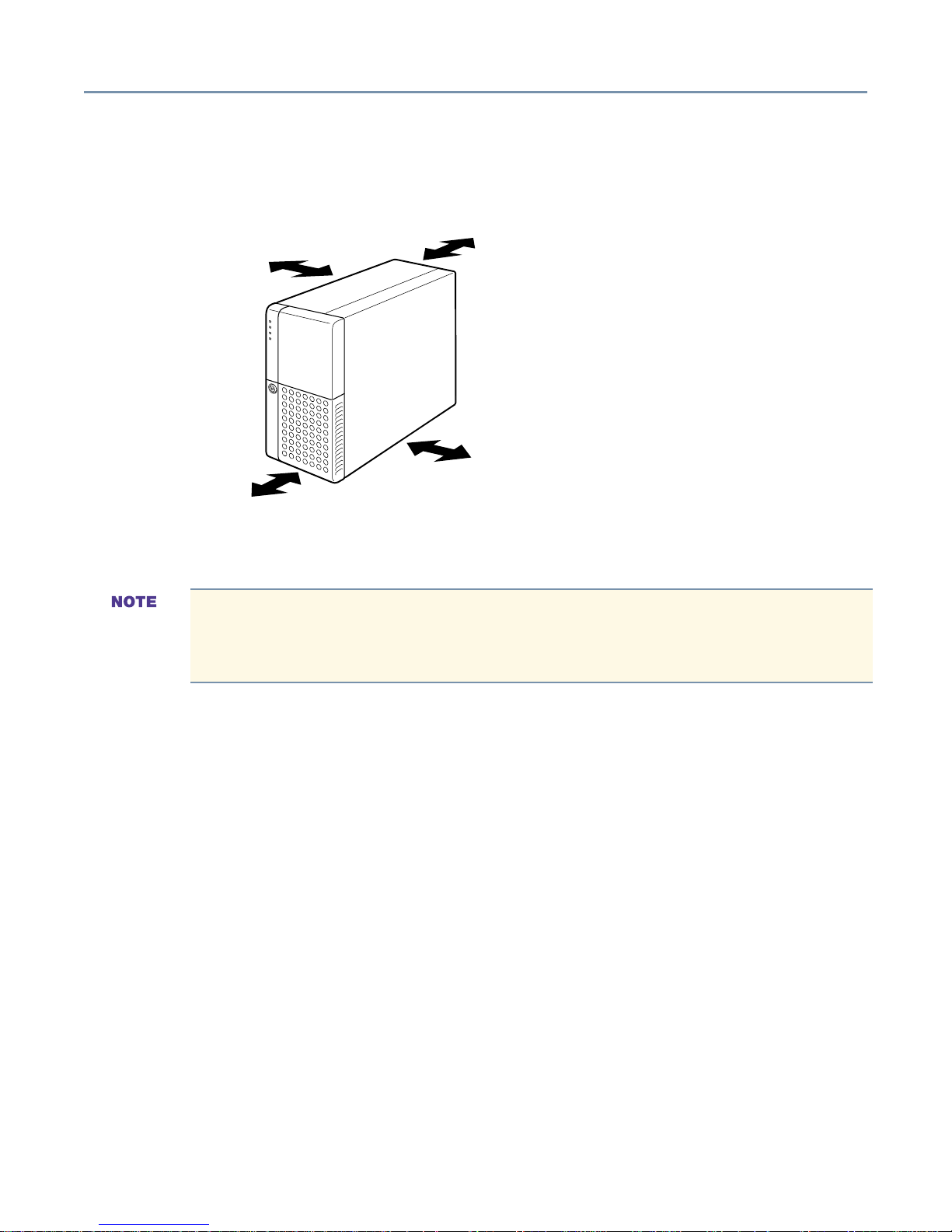
Environmental considerations for pedestal models
Allow sufficient space around the server and connected peripheral devices for installation
and maintenance. The following illustration shows recommended minimum clearance.
2 inches (5 cm)
12 inches (30 cm)
Recommended minimum clearances for pedestal models
8 inches (20 cm)
2 inches (5 cm)
Environmental considerations for rack models
Installing a Toshiba Magnia 3310/3310R in a rack requires special knowledge and
skills. Toshiba recommends that you contact an authorized Toshiba Magnia
service provider.
In addition to the general environmental considerations, keep in mind these additional
points:
❖ Use only the rack and rack-mount kit specified by Toshiba to install a rack model.
❖ The equipment rack must provide sufficient airflow to the server to maintain proper
cooling. Allow 24 inches (60 cm) of clearance in front and behind the rack.
Getting Started Power requirements 23
Power requirements
To ensure proper grounding of the server and avoid a possible fire hazard, only
use the power cable provided with the server.
The EPS-R power supply unit has a 10 amp over-current protective circuit. Before
plugging the power cable into a wall outlet—particularly if the server is mounted in a
rack—make sure the AC power source and the over-current protector (circuit breaker
current rating) are sufficient to handle the requirements of the server and its connected
peripheral devices.
The current rating of the server is 4 amps. To ensure a continuous supply of power to the
server, Toshiba recommends the use of an uninterruptible power supply (UPS).
If you have questions about the wiring of your AC power source, consult an authorized
electrician.
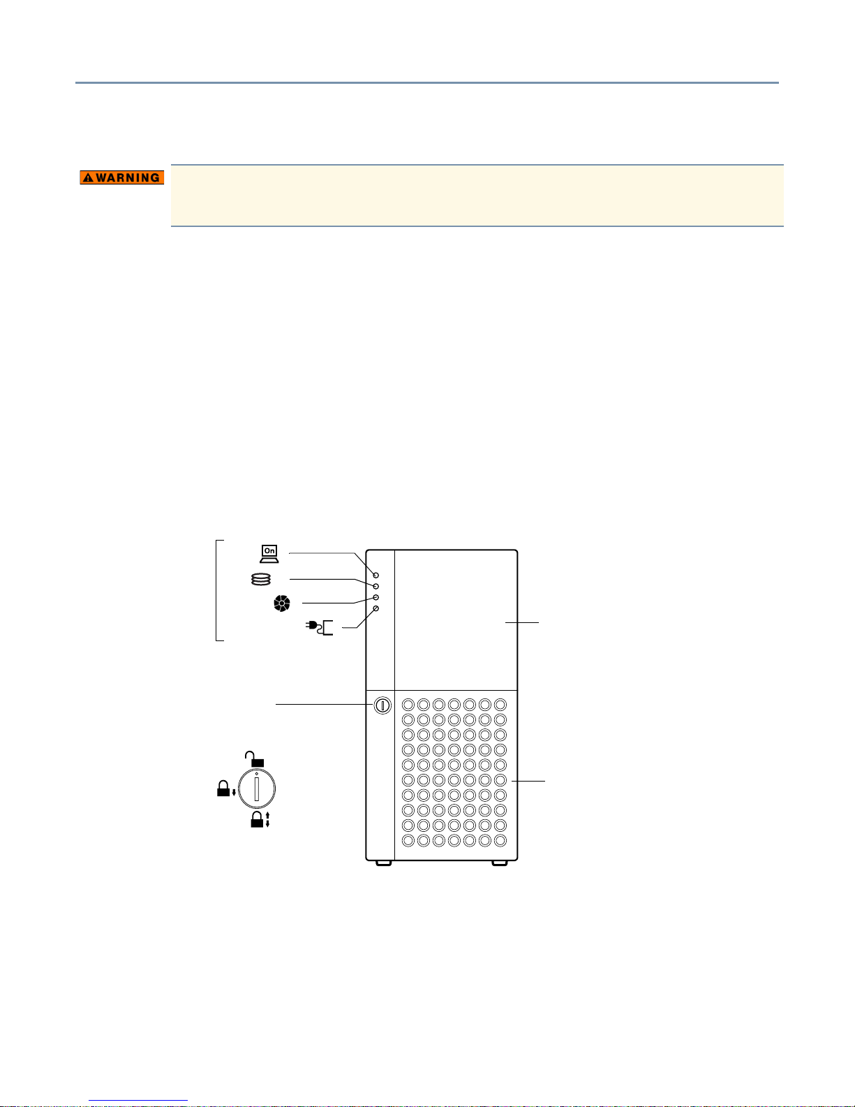
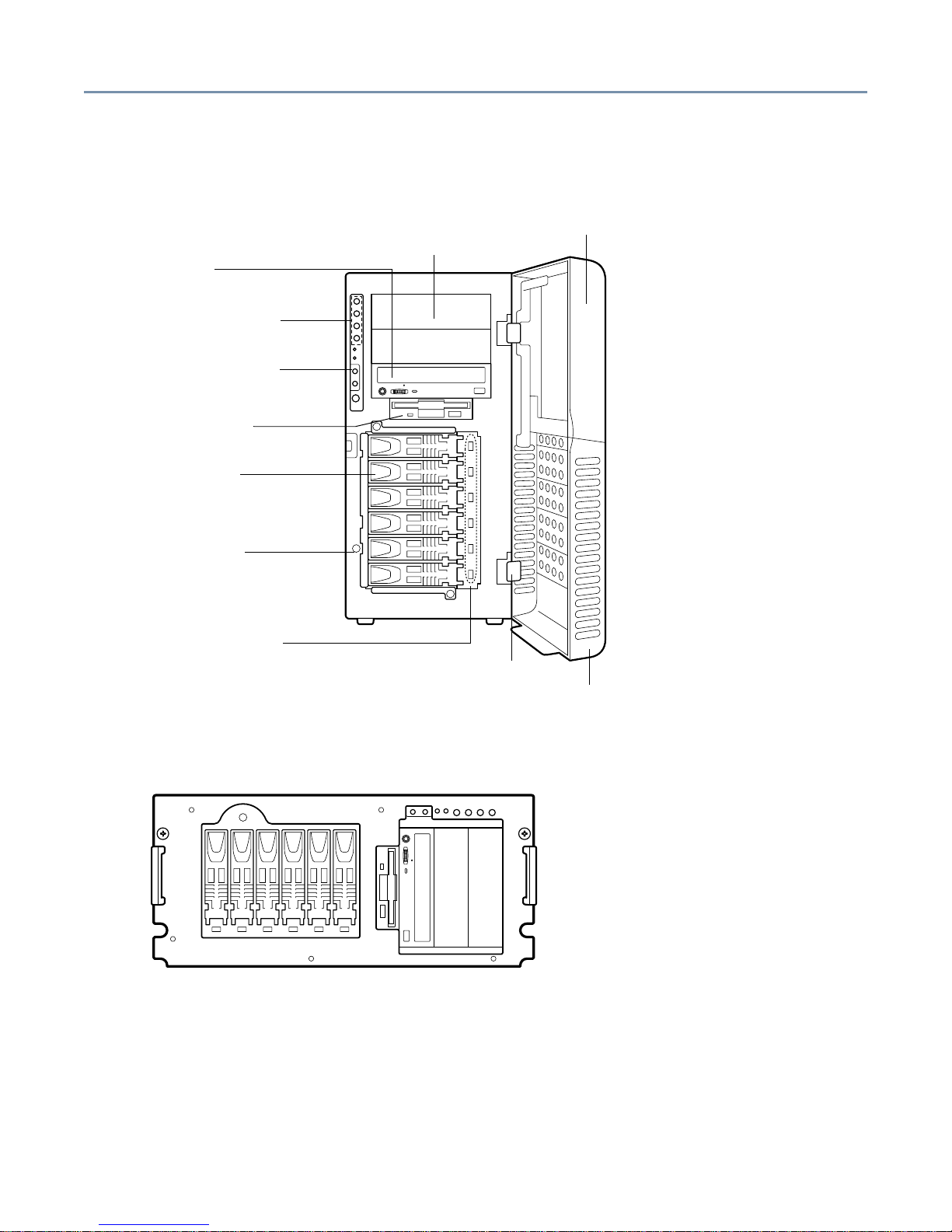
Front of the server
Power ( )
System status
indicators
Front Panel Lock
Limited access
Upper door - The upper door allows access to the indicators, switches, device bay,
CD-ROM drive, and floppy disk drive.
Disk ( )
Fan fault ( )
Power unit fault ( )
Full access
No access
Upper door
Front door panel
Front door panel - The front door panel allows access to the hard disk drives and the side
panel lock.
Getting Started Front of the server 24
Front panel lock - Rotating the panel lock releases the access panel, allowing you to
remove the panel and gain access to the server’s internal components. The Side Panel
Lock is illustrated on the following page.
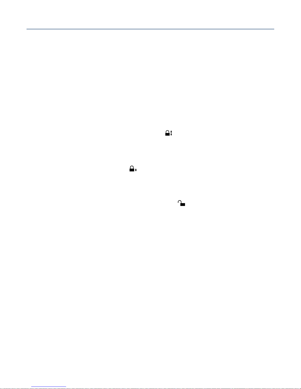
Limiting access to server controls
Pedestal model servers have an upper door and front door panel. The door and panel
can be locked to provide the following three levels of security:
❖ No access - When the front panel lock is set to the “No access” position, the security
key is required to access the server’s front panel controls and internal components.
To prohibit server access, close the upper and lower front doors, insert the key into
the door lock and turn it to the No Access ( ) position.
❖ Limited access - Opening the upper door allows access to the power button, reset
button, device bay, CD-ROM drive, and floppy disk drive. To permit access only to
these items, close the lower door panel, insert the security key into the door lock and
turn it to the Limited Access ( ) position.
❖ Full access - Opening the upper and lower doors allows access to the server’s power
button, reset button, device bay, CD-ROM drive, floppy disk drive, and hard disk
drives. To permit full access to the server controls and drives, insert the security key
into the door lock and turn it to the Full Access ( ) position.
Getting Started Front of the server 25
Server controls, indicators and drives
Toshiba Magnia 3310 (pedestal)
Front door (upper)
Device bay
CD-ROM drive
System status indicators
Operation buttons
Floppy disk drive
Hard disk drive
Side panel lock
HDD status indicator
Removable door hinge
Toshiba Magnia 3310R (rack)
Front door (lower)
Getting Started Front of the server 26
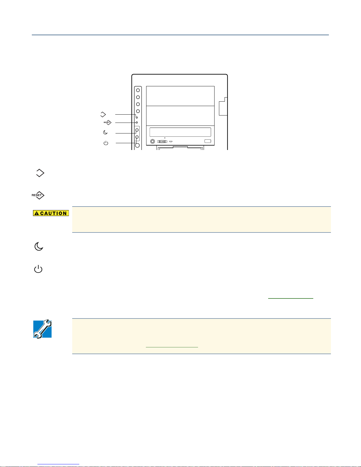
Operation buttons
NMI button ( )
Reset button ( )
Sleep button ( )
Power button ( )
Operation buttons
NMI
NMI button - Provided exclusively for use by authorized Toshiba Magnia service
NMI
providers.
Reset button - Restarts the server.
To avoid data loss or corruption, never use the Reset button while the activity
indicator on the floppy disk drive, CD-ROM drive, or hard disk drive(s) is on.
Sleep button - Not enabled.
Power button - Press this button to power-down the server. Placing the server in security
mode disables the power button. To power-down the server while it is in security mode,
the user must have shutdown rights. To reactivate the power button, enter your user or
administrator password. For more information on security mode, see Security menu
on
page 111.
TECHNICAL NOTE: The procedure for shutting down the server depends on the
operating system installed on the server. For more information on turning the
server on and off, see Inside the server
on page 41.
Getting Started Front of the server 27
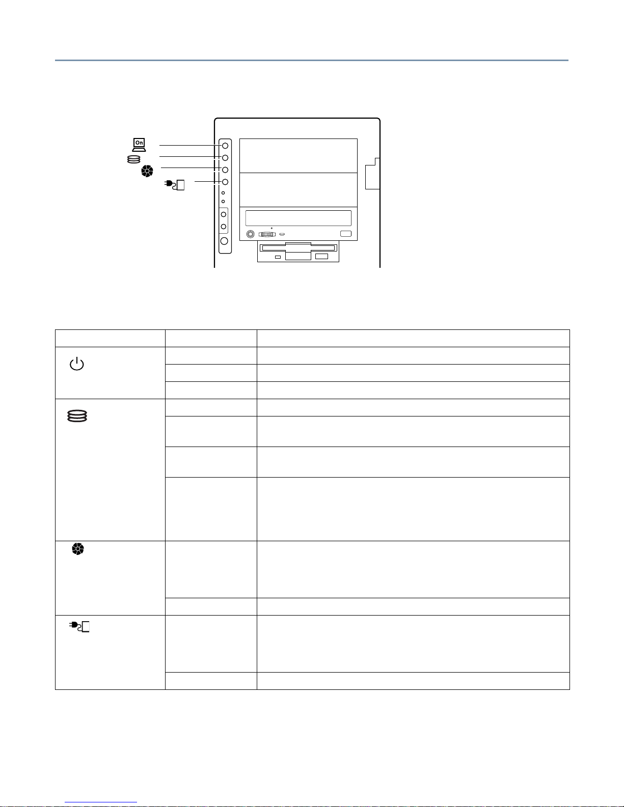
System indicators
Power indicator ( )
Disk indicator ( )
Fan fault indicator ( )
Power unit fault indicator ( )
System indicators
The following table describes the operation of the system indicators.
Indicator Status Description
Off AC power is not being supplied to the server.
Power
Amber AC power is being supplied but the server is turned off.
Green Server is running normally
Off Disk is out of operation
Hard Disk
Drive (HDD)
Flashing amber Disk array is being rebuilt (valid only when the RAID
controller is in use.)
Amber Disk failure has occurred (valid only when the RAID
controller is in use.)
Flashing green Disk drive in operation.
(For models without a RAID controller, this indicator also
flashes when another SCSI device connected to the onboard SCSI controller is running.)
Fan Fault Off Indicates one of the following:
- Out of operation
- Cooling fan is operating normally.
Amber The Cooling fan has failed.
Power Fault Off Indicates one of the following:
- Out of operation
- The power supply is operating normally.
Amber The power supply unit has failed.
Getting Started Front of the server 28
Detachable door hinges (pedestal model only)
The hinges allow you to remove the server’s front door panels.
Device bay
The upper 5.25-inch device bay contains three slots (one occupied by the CD-ROM
drive).
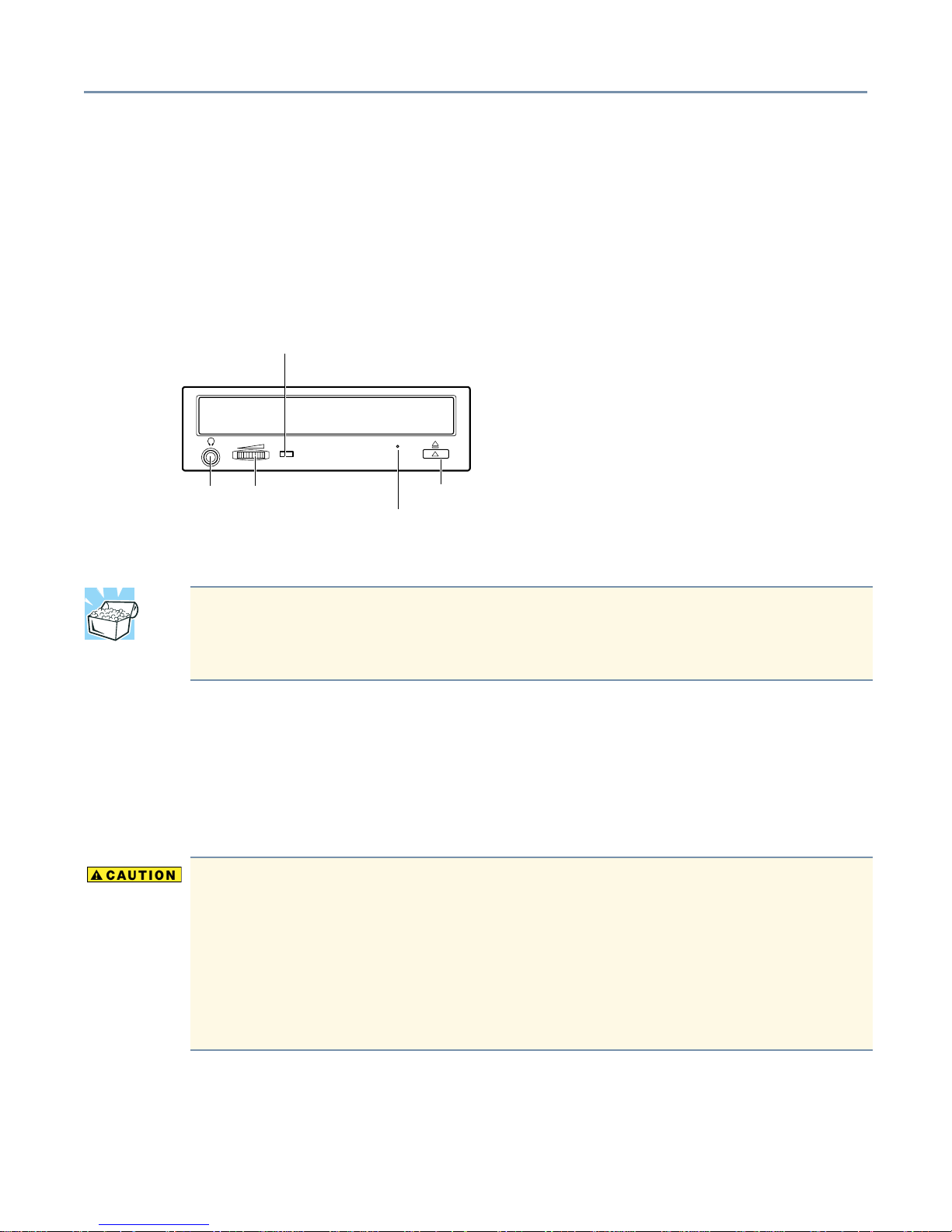
CD-ROM drive
CD-ROM drive status indicator
Stereo
phone jack
Volume control
Eject button
Eject hole
Disc tray - Use to insert CDs in the CD-ROM drive.
HINT: The CD-ROM drive has a disc tray equipped with retainers to hold the CD in
place on the tray. It is only necessary to use these retainers if the server is
mounted in a rack.
Headphone jack - Use to connect headphones or an earphone.
Manual eject pinhole - Use to manually release the disc tray if it does not open when you
press the eject button while the server is on. To release the disc tray, insert a slender
object, such as a straightened paper clip, through the pinhole and press gently.
To avoid damaging the CD-ROM drive when manually ejecting a compact
disc:
Turn off the server before manually opening the disc tray.
Never use fragile objects, such as the tip of a pencil, to eject the disc tray. The
object may break and damage the CD-ROM drive. Remove any CDs from the
CD-ROM, whenever the drive is not in use.
Volume control dial - Use to adjust the audio output level of the server.
Activity indicator - Illuminates when the CD-ROM is being accessed.
Getting Started Front of the server 29
Stop/Eject button - Use to open and close the disc tray.
To avoid damaging the CD-ROM drive, never press the eject button while the
status indicator is on.
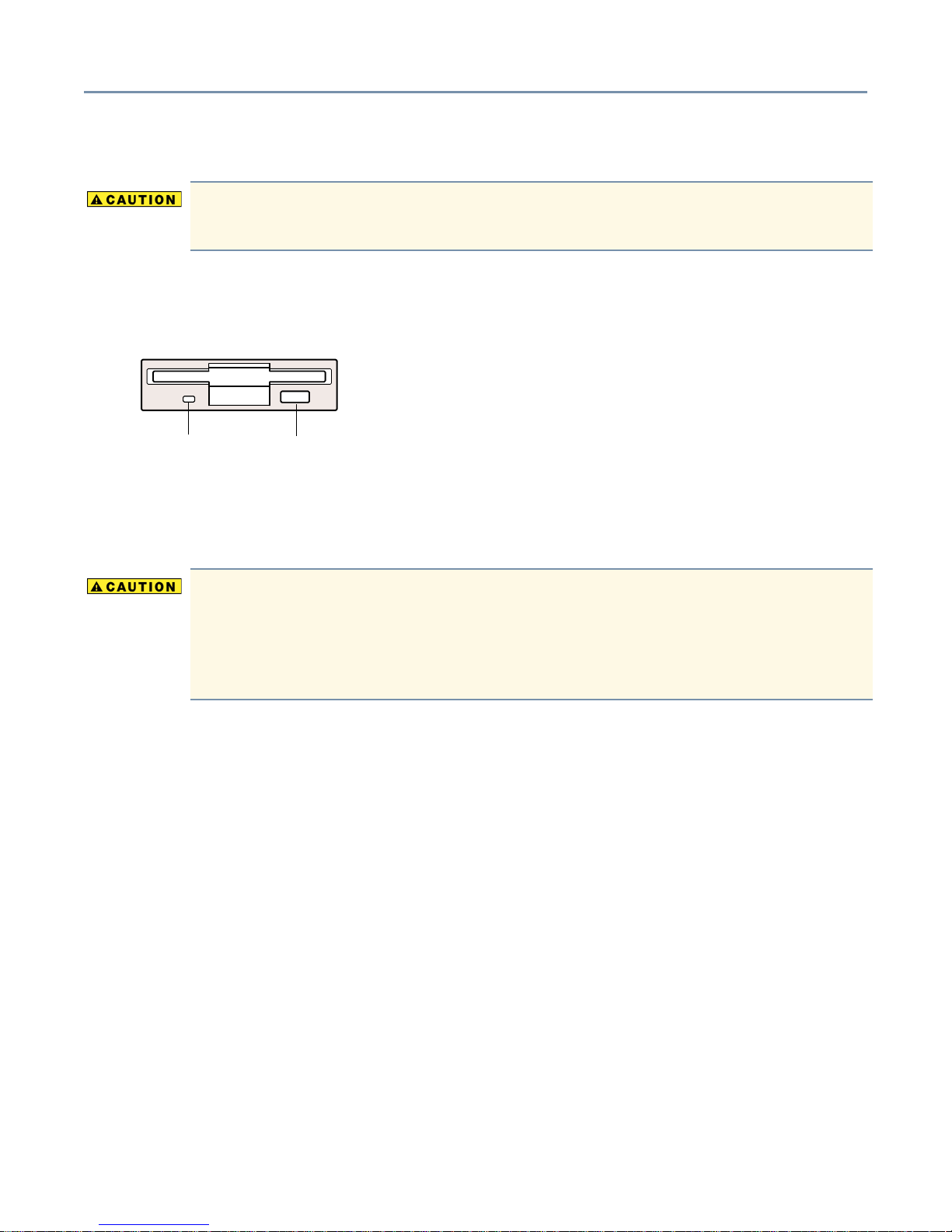
Floppy disk drive (FDD)
The floppy disk drive supports 3.5-inch double-density (720 KB) and high-density
(1.44 MB) diskettes.
Activity
indicator
Eject
button
Activity indicator - Illuminates whenever the floppy disk drive reads or writes data.
Eject button - Releases the diskette from the drive.
To avoid losing or corrupting data stored on the diskette, never press the eject
button while the FDD activity indicator is on.
Remove the diskette from the floppy disk drive whenever the drive is not in
use.
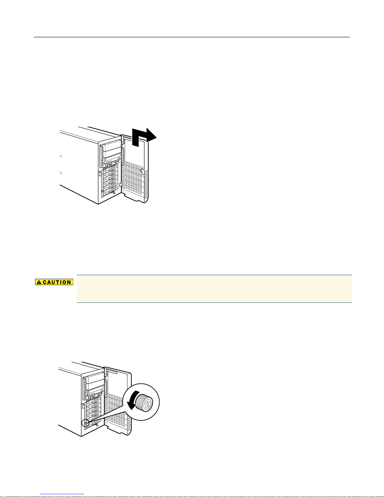
Getting Started Removing and replacing the server panels 30
Removing and replacing the server panels
To remove the front panel:
1 Release the door lock and open the upper and lower doors as a single unit.
2 Lift the lower panel to unhook its hinges and remove it from the server.
Removing the front panel
To install optional devices inside the server, you need to remove the side panel if your
server is a pedestal model, or the top panel, if your server is a rack model.
Removing the side panel (pedestal model)
When sliding off a server panel, be careful not to catch your finger between it and
the server.
To remove the side panel:
1 Shut down the server, turn off the power, and unplug the power cable.
2 Turn the side panel lock counter-clockwise to release it.
Releasing the side panel lock

Getting Started Removing and replacing the server panels 31
3 Slide the side panel toward the rear of the server to remove it.
Removing the side panel
Replacing the side panel (pedestal model)
Follow these steps to replace the side panel:
1 Carefully slide the side panel onto the server.
2 Turn the side panel lock to the locking position.
3 Make sure all panels are locked, then close the front doors.
4 Plug in the power cable(cables, if you have a redundant power supply).
Removing the top panel (rack models)
Follow these steps to remove the top panel:
1 Shut down the server, turn off the power, and unplug the power cable.
2 Unplug the display cable, keyboard cable, and others as appropriate.
3 Loosen the 2 screws securing the server to the rack.

Getting Started Removing and replacing the server panels 32
4 Grasp the handles on the server’s front panel, and carefully slide the server from the
rack until the rail latches lock the server in its fully-extended position.
Pulling out the server (rack model)
5 Turn the side panel lock to release the lock.
6 Slide the top panel towards the rear of the server to remove it.
Replacing the top panel (rack models)
Follow these steps to replace the top panel:
1 Carefully slide the top panel onto the server.
2 Turn the side panel lock to the locking position.
3 Press the rail latches inward to release the server from its locked position, then slide
the server into the rack.
4 Tighten the two screws to secure it.
5 Plug in all cables.
6 Plug in the power cable.

Getting Started Rear view of the server 33
Rear view of the server
Redundant EPS-R module
I/O
connectors
Expansion
slots
Rear view of the server
AC receptacle
AC receptacle
Power supply release (push down to release)
Power supply release (push down to release)
Standard EPS-R module
Power supply unit
Toshiba Magnia 3310/3310R servers have two EPS-R power supply modules—providing
the server with power supply redundancy and load sharing capabilities.
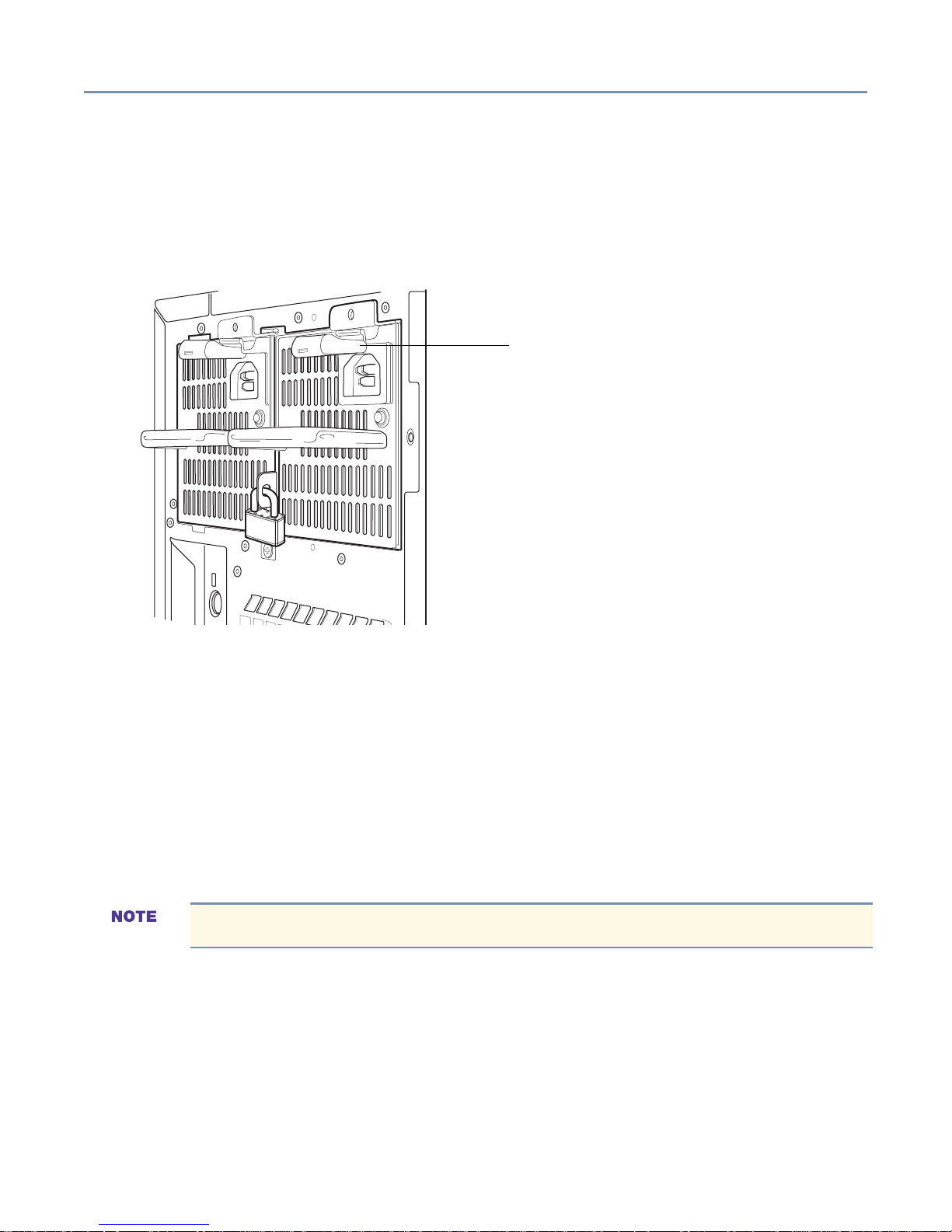
Getting Started Isolating EPS-R cage and cooling fan unit failures 34
Securing power supply units
To prevent unauthorized removal of the power supply unit(s), you can install a security
lock.
To secure the power supply unit(s), place a commercially available padlock (not
provided) through the security lock tap between the two power supply units.
Power supply release (push down to release)
Placing the security lock
Isolating EPS-R cage and cooling fan unit failures
To regulate the temperature inside the server, the Toshiba Magnia 3310/3310R is
equipped with:
❖ Intake fan module(s) - For redundancy, up to two intake fan modules can be installed
in tandem in the fan bays located in the forward lower section of the server chassis.
❖ Exhaust fan module(s) - The exhaust fan module (duct) contains a single fan, but can
be fitted with an additional exhaust fan module for redundancy.
When a 3.06 GHz CPU module is installed, the exhaust fan duct is not required.
❖ EPS-R cooling fans - The power supply units are housed in the EPS-R cage. Each
power supply comes with a fan.

Getting Started Isolating EPS-R cage and cooling fan unit failures 35
exhaust fan duct
EPS-R module
Standard
exhaust fan
Redundant
exhaust fan
Location of system cooling fans (fan duct not installed on all models)
Indication of a failure
A power supply and cooling fan can be added to the EPS-R cage to make them
redundant.
Standard and redundant fans operate at all times during regular operation.
A CPU fan is attached to the 3.06 GHz CPU module. This fan cannot be arranged
in a redundant configuration.
The power unit fault indicator lights amber if the second power supply fails, while the fan
fault indicator lights amber if any cooling fan fails.
If one of the redundant cooling fans fails, the server can be kept running in downgraded
operation. If two or more modules fail, the server must be shut down immediately.
Standard intake fan
Redundant intake fan
Exhaust fan- The exhaust fan module comprises the primary exhaust fan and the
exhaust duct.

Getting Started Isolating EPS-R cage and cooling fan unit failures 36
Intake fan - The server has two intake fan bays. If one module is installed and the intake
fan on that module fails, the server can overheat, resulting in lost or corrupted data and/
or programs. In this case, shut down the server immediately and replace the failed fan. If
two modules are installed and one module fails, the server will continue running in a
“downgraded operational state”. Depending on the temperature and installation
conditions, prolonged downgraded operation could shorten the service life of each
system component. If both intake fans fail, shut down the server immediately and replace
the failed fans.
HDD status indicators
The Toshiba Magnia 3310/3310R server can accommodate up to 6 hard disk drives. The
status of each hard disk drive is indicated by both a DC power indicator and a status
indicator under each drive bay.
Lamp Status Meaning
DC
power
Status Off No data is being read or written.
Off No hard disk drive is installed.
No power is supplied to the hard disk drive.
Green Power is supplied to the hard disk drive.
Green Data is being read or written.
Amber Failure condition has occurred (valid only when the RAID
controller is in use).
Flashing
amber
The disk array is being rebuilt (valid only when the RAID controller
is in use).
When the status indicator is amber, and your system has a built-in RAID controller the
corresponding hard disk drive may be faulty. If the drive is defective, replace it. For more
information on changing hard disk drives, see Replacing a hard disk drive on page 95.

Getting Started Isolating EPS-R cage and cooling fan unit failures 37
Identifying the AC power connector and I/O signal ports
This section provides a description of the server’s AC power connector and I/O port. It
also provides information on connecting peripheral devices to the server.
TECHNICAL NOTE: The output voltages from the I/O connectors on the back of
the server do not exceed 12V.
Mouse connector
Keyboard connector
Serial 1 connector
RGB connector
Ether1 connector
USB 1 connector
USB 2 connector
Ether2 connector
Serial 2 connector
Ether
Ether
Parallel
connector
Ether1
indicator(ACT)
Ether1
indicator(LNK)
Connecting peripheral devices
Icon Description
PS/2 Keyboard connector
PS/2 Mouse connector
Parallel printer connector
RGB display connector
USB 1 connector
USB 2 connector
Ether2
indicator(ACT)
Ether2
indicator(LNK)

Getting Started Isolating EPS-R cage and cooling fan unit failures 38
Icon Description
Ether
Ethernet LAN Connectors
Communication status indicator (ACT)
Flashing green - Data being transferred
Off - No connection
Link communication status indicator (LINK)
Green - Connected, but waiting
Off - Not operating
Ether1 Link (1000/100 Mbps) indicator
Green - 1000 Mbps
Yellow - 100 Mbps
Ether2 Link (100/10 Mbps) indicator
Green - 100 or 10 Mbps
Serial 1 connector, used to connect an RS-232C-compliant device.
USB ports 1 and 2. When connecting a USB device, be sure that the operating
system supports USB devices.
Expansion slots
The motherboard has a total of six expansion slots. The PCI slots comply with PCI 2.2
standards. For more information, see Installing expansion cards on page 98.

Getting Started Connecting peripheral devices 39
Connecting peripheral devices
Use the I/O connectors on the back of the server to connect peripheral devices such as
the keyboard, mouse, display and so on. Be sure the devices are properly connected
before turning on the server.
To connect peripheral devices to the server:
1 Make sure that the server and all connected peripheral devices are turned off and
that their power cables are not plugged into an AC outlet.
2 Using the proper interface cable, connect each peripheral device to an appropriate
connector on the server. If the plug on the interface cable has thumbscrews, tighten
the thumbscrews sufficiently to secure the cable.
Connecting peripheral devices
3 Tighten any connector screws.
4 Plug the power cables from the server and peripheral devices into AC outlets. Make
sure all peripheral devices are properly connected before turning on the server.

Getting Started Connecting AC power 40
Connecting AC power
Handling the cord on this product will expose you to lead, a chemical known to the
State of California to cause birth defects or other reproductive harm. Wash hands
after handling.
Before connecting the server to an AC outlet, make sure the power source has sufficient
current capacity for the power requirements of the server system. If the system’s power
consumption exceeds the capacity of the power source, the server can be damaged.
Always connect the server to a grounded AC outlet.
Never connect the server to the same AC outlet as an appliance that has a high power
consumption or that generates electrical noise, such as an air conditioner or photocopier.
HINT: Use an uninterruptible power supply (UPS) to avoid losing data when an
unexpected power failure occurs.
To connect the server to an AC power source:
1 Plug the power cable(s) into the connector on the back of the server.
Securing the power cable
2 Plug the power cable into an AC outlet or, preferably, the power output connector of
an uninterruptible power supply (UPS).
Be sure to use the power cable supplied with the server. Using another power
cable could create a fire hazard.

Getting Started Inside the server 41
Inside the server
Power
supply module
Cooling fan
(exhaust fan)
Internal
battery
Expansion
slots
Motherboard
Memory slots
CPU socket
5.25"
Device bay
Hard disk
drive
Hard disk backplane
board
Cooling fan (intake fan)
Exhaust fan duct
When a 3.06 GHz CPU module is installed, the exhaust fan duct is not required.
Motherboard
The motherboard contains two CPU sockets, six memory module slots, and six PCI
expansion card slots.
Cooling fans
The server contains cooling fans for its hard disk drives, power supply, and CPU. You can
install an additional fan module for redundancy. Then, if one fan module fails, the
remaining module will provide sufficient cool air to allow the server to continue running
(downgraded operation).
If a cooling fan fails, the fault indicator flashes to indicate a failure condition. Replace or
repair the failed cooling fan as soon as possible. Prolonged downgraded operation could
shorten the service life of each system component. If the remaining cooling fan fails,
important data and programs could be corrupted or lost. For more information on fault
indications, see System indicators
A CPU fan is attached to the 3.06 GHz CPU module. This fan cannot be arranged
in a redundant configuration.
on page 27.

Getting Started Turning on the server 42
CPU sockets
Use to install CPU modules. For instructions, see Before Installing and Removing a CPU
module on page 70.
Internal battery
The internal RTC (Real-Time Clock) battery supplies power to the server’s clock, which
provides timing signals for system timesharing operations. The battery is located on the
motherboard. For instructions on replacing the RTC battery, see Replacing the internal
battery on page 84.
Memory bank
The memory bank contains six slots, allowing you to install up to six memory modules in
the server. For information on upgrading system memory, see Memory modules on page
60.
Expansion slots
The motherboard has six PCI expansion slots: two 64-bit/100 MHz slots, two 64-bit/66
MHz slots, and two 32-bit/33MHz slots.
Turning on the server
TECHNICAL NOTE: Always allow at least 10 seconds to elapse between turning
the server off and turning it back on again. If the server is turned on before 10
seconds have elapsed, it may malfunction.
1 Check that all the peripheral devices, such as the monitor, keyboard, and mouse, are
properly connected to the server.
2 Check that all power cables are connected to grounded AC outlets or an
uninterruptible power supply (UPS).
3 Turn on the monitor.
4 Press the power button.
The power indicator ( ) lights green.

Getting Started Turning on the server 43
Using Wake-On-LAN
The Toshiba Magnia 3310/3310R server has Wake-On-LAN functionality. This feature
allows a remote client computer to start the server by transmitting a server startup packet
to the server network interface card.
The Wake ON LAN function is enabled after booting up the OS to an idle state when the
Wake On LAN function is enabled through the BIOS.
The onboard network adapters on the Toshiba Magnia 3310/3310R (Ether1 and Ether2)
support the Wake On LAN function. You can boot the server from a client machine over
the network using Remote Wake On Tool. Use the following procedure to change the
network driver configuration to enable the Wake On LAN function.
If installing Windows 2000 manually, perform this procedure after completing the
steps described in Manually Installing Windows 2003 Server on page 154.
If using the Server Setup Tool to install Windows 2000 automatically, perform this
procedure after completing the steps described in Post Installation (Windows
2000) on page 160.
®
To enable Wake On LAN function for Ether1:
1 Select Control Panel, Hardware, then Device Manager.
2 Within the Network Adapters, Intel(R) 82545EM Based Network Connection
Properties from the Details tab.
3 Set “Enable PME” to “Enabled”, and set “Wake on Settings” to “Wake on Magic
Packet”, then select “OK”.
4 Select the “Network Adapters”-“Antler) 82545EM Based Network Connection”-
”Properties”-“Power Management” Tab.
5 Set both the “Allow this device to…” check box and “Allow the computer to…” check
box on, then select “OK”.
To enable Wake On LAN function for Ether1:
1 Select “Control Panel”-“Hardware”-“Device Manager”.
2 Select the “Network Adapters”-“Intel(R) 8255x-based PCI Ethernet Adapter (10/
100)”-“Properties”-“Details” Tab.

Getting Started Power On Self Test (POST) 44
3 Set “Enable PME” to “Enabled”, and then select “OK”.
TECHNICAL NOTE: If the server is turned on through the Wake-On-LAN function
and turned off again before the Windows LAN driver is loaded, a startup fault may
occur the next time you attempt to start the server using the Wake-On-LAN
function. If this occurs, disconnect, then reconnect, the power cable from the AC
outlet.
Power On Self Test (POST)
Pressing the power button turns on the server and starts the Power On Self Test (POST).
The POST is a self-diagnosing function that automatically executes each time the server
starts. The motherboard, BIOS and BMC firmware revisions, microprocessor, memory,
keyboard, and some peripheral devices connected to the server are automatically
checked by the POST. During the memory test, the POST accesses and tests the
server’s memory, and then displays the amount of system memory on the screen.
Depending on how the server is configured, following the POST a message similar to the
following appears on the screen:
Press F2 to enter SETUP
Pressing the F2 key starts the BIOS setup utility. If you do not press F2, system startup
continues.
If an error is detected by the POST (depending on the error condition) one of the
following occurs:
❖ A beep sounds during testing
❖ An error code and message appear after the POST completes
Booting the server
You can boot the server from any of the following devices:
❖ Floppy disk drive
❖ Hard disk drive
❖ CD-ROM drive
Starting the server from the floppy disk drive

Getting Started Booting the server 45
1 Make sure that the CD-ROM drive is empty.
2 Insert the Startup Disk into the floppy drive.
3 Press the power button to start the server.
Starting the server from the hard disk drive
If an operating system is installed on the server, you can start the server from the hard
disk drive. To start the server, check the floppy disk drive and the CD-ROM drive to make
sure they are empty, then press the power button to start the server.
If a bootable CD is loaded in the CD-ROM drive and it is recognized by the
system, the server will not recognize the hard disk drive as a boot device even if
you eject the CD. Press Ctrl+Alt+Delete to restart the server
Starting the server from the CD-ROM drive
1 Make sure that the floppy disk drive is empty.
2 Press the power button to start the server.
3 Press <F2> to start the BIOS setup utility, then select “CD-ROM Drive” from the boot
menu.
+Removable Devices
+Hard Drive
CD-ROM Drive
Network Boot
4 Press <+> to move the CD-ROM drive’s order up in the boot sequence.
To start the server using the CD-ROM drive, the startup CD-ROM must be
inserted into the drive before the Onboard SCSI Controller BIOS setup menu
appears after the power button is turned on. If the startup CD-ROM is placed in
the drive too late, restart the server by pressing the <Ctrl>+<Alt>+<Delete> keys
simultaneously. Once the startup CD-ROM is recognized, the hard disk drive is
disabled from starting the server, even if the CD-ROM is ejected.
5 Press <F10>, then <Enter> to exit the BIOS setup.
When you press <F10>, any changes are saved, and the system restarts.
6 Immediately press the CD-ROM drive’s eject button and insert the CD-ROM for
booting the OS.

Getting Started BIOS setup 46
BIOS setup
The server’s system setup can be changed using the BIOS setup Utility. You can make
changes to the BIOS setup even if an operating system has not been installed on the
server. The system settings you enter are written in the CMOS and flash memory and
take effect when you restart the server. BIOS settings are used for reference during the
POST.
If the server hardware does not support the values you enter, an appropriate error
message appears on the screen when the POST routine completes. If this occurs,
change the setting using the BIOS Setup Utility.
Setting the system configuration
The system configuration for your Toshiba Magnia 3310/3310R server was set at the
factory. However, if you install optional items after shipment, you may need to reconfigure
the server. For detailed information on configuring the server, see Chapter 3, System
Configuration Setup on page 106.
BIOS Setup Utility
In addition to the Magnia 3310/3310R Software and Documentation CD, the BIOS Setup
Utility allows you to configure the hardware installed in the server.
Onboard SCSI Utility
The Onboard SCSI Utility allows you to configure the server’s onboard SCSI devices and
onboard SCSI controller.
Turning off the server
The procedure for turning off the server depends on the operating system installed on
the server. Always perform either a normal or an automatic shutdown when turning off
the server.
Performing a normal shutdown
To perform a normal shutdown under operating systems which do not support ACPI:
1 Shut down the operating system. For instructions, refer to the user’s guide that came
with your operating system.
2 Press the power switch Off. The system will immediately power-down.

Getting Started Turning off the server 47
Using the power switch to shutdown an ACPI-compliant system causes any
running application software to abort before completing the normal termination
process. This could result in data loss or damage any running applications.
The buzzer should sound a continuous tone about 4 seconds after you press the power
button. Releasing the power button before the buzzer sounds terminates the power-down
operation.
Performing an abnormal system shutdown
If an error occurs during system shutdown, the shutdown routine can be stopped by
performing an abnormal system shutdown. Initiating an abnormal system shutdown
causes all unsaved data in open files to be lost.
To initiate an abnormal system shutdown, press the reset button and power button
simultaneously.

48
Chapter 2
Connecting Hardware
Devices
Installing optional devices
This chapter contains information and instructions on installing and removing optional
devices.
Before you start
❖ Before installing an optional device, please read both the manufacturer’s instructions
and the installation instructions in this manual.
❖ The procedures described in this chapter require specific technical knowledge and
experience. If you have no experience installing/removing optional devices, or if the
job seems difficult, please consult an authorized Toshiba Magnia service provider.
Toshiba assumes no liability for damages if you install and/or remove optional devices
yourself.
Never handle any electrical component that is not described in this manual. Some
parts carry high voltages and are dangerous.To avoid electric shock, shut down
the server and disconnect the power cable before performing any server
maintenance.
To avoid electric shock, never operate the server with the access panel removed.

Connecting Hardware Devices Installing optional devices 49
Selecting a workplace
❖ Before performing server maintenance, select a workplace that is as free of dust as
possible.
❖ The ambient temperature and relative humidity should range between 50°F to 95°F
(10°C to 35°C) and 30% to 80%. Avoid exposing the server to drastic temperature
fluctuations that could cause condensation.
❖ Never install or remove devices in a static-inducing environment (on a carpet, for
example). Electronic devices can fail if they are exposed to electrostatic discharge
(ESD).
Working safely
❖ Make sure you read and understand the instructions and precautions in this guide
before performing server maintenance.
❖ Perform the steps in each procedure in the order written.
❖ Before disconnecting any cables, note their positions to make sure you can reconnect
them correctly.
❖ Check cable connectors for broken or bent pins. If a cable connector has screws,
tighten the screws when securing the cable.
❖ If a failure occurs, consult your authorized Toshiba Magnia service provider.
Internal server components can be seriously damaged by static electricity.
Wear a wrist or heel ground cable to discharge static electricity carried on your
body. If such equipment is not available, touch a grounded metal object to
discharge static electricity before working on sensitive electronic components.
Once you remove a device from its antistatic package, place the antistatic
package and the device on a flat, grounded surface. Store the antistatic
package for future use.
To prevent static build-up, never drag the server when moving it.

Connecting Hardware Devices Maintenance overview 50
Maintenance overview
Never disassemble the server more than described in this manual. Failure to
observe this precaution could result in electric shock, cause a system fault, or void
your warranty.
When performing maintenance on the server, follow these general steps:
1 Carefully read the precautions mentioned previously in this chapter. See Installing
optional devices on page 48.
2 If the server is running, shut down the operating system, turn off all the peripheral
devices connected to the server, then press and hold the power button to turn off the
server. For more information, see Turning off the server on page 46.
3 Unplug the power cable from the AC outlet or UPS (uninterruptible power supply),
then disconnect all signal cables connected to the I/O connectors on the back of the
server.
4 Remove the server’s access panel.
❖ For pedestal models, see Removing the side panel (pedestal model) on page 30.
❖ For rack models, see Removing the top panel (rack models) on page 31.
5 Perform the required maintenance.
Make sure that components handled during system maintenance are properly
installed and connections are securely seated. Also check that no tools or
hardware items are left inside the server.
6 Reinstall the server’s access panel.
❖ For pedestal models, see Replacing the side panel (pedestal model)
❖ For rack models, see Replacing the top panel (rack models)
7 Reconnect all signal cables.
8 Plug the power cable into an AC outlet.
9 Press the power button to turn on the server, then run any required system checks.
on page 32.
on page 31.
Some optional devices require you to reconfigure the server’s software and change
jumper, and/or DIP switch settings before the device can be used. For more information,
see BIOS Setup Utility on page 106.

Connecting Hardware Devices Maintenance overview 51
In addition to the instructions in this chapter, refer to the manufacturer’s user manuals for
the devices you are installing/removing.
Working on rack-mounted servers
Read the following warnings before performing maintenance on a rack-mounted
server. Failure to adhere to these warnings can result in serious injury and/or
damage to equipment.
❖ Never attempt to install or remove a server by yourself. At least two people are
required to install a server into a rack. Three people are required to install a server at
a height greater than 31 units of vertical rack space (approximately 54 inches). Be
particularly careful when installing a server near the top of a rack or in a location that
requires you to lift the server higher than chest level.
❖ Never slide the server and another unit (such as an expansion disk unit) out of the
rack at the same time. Extending more than one device from the rack may cause it to
become unstable.
❖ Never place additional weight or apply an excessive load to a server or other unit that
is extended from the rack. Such a load may damage the rack’s rails or cause the rack
to become unstable.
❖ Never lean objects against the rack, and do not lean against it. The rack may become
unstable and cause serious injury.
❖ When working at high locations around the rack, never lean ladders directly against
the rack or against units installed in the rack. The installed units may be damaged, or
the rack may become unstable and tip over, causing injury.
Sliding the server from the rack
If the rack contains additional servers that are currently in use, be careful not to
touch any hard disk drive eject levers, AC switches, or other important buttons,
levers or switches on those servers.
1 Make sure that the cables connected to the server are long enough to allow the
server to be extended from the rack. If the cables are too short, disconnect them to
avoid damaging the cables or the server.
2 Loosen the two thumbscrews securing the server to the rack.

Connecting Hardware Devices Maintenance overview 52
3 Grasp the handles on the server’s front panel, and carefully slide the server from the
rack until the rail latches lock the server in its fully extended position.
Rail latch
Sliding the server from the rack
4 To ensure that the server is locked in position, using light pressure, try to slide the
server back into the rack.
Sliding the server into the rack
1 Press the rail latches inward to release the server from its locked position, then slide
the server into the rack.
2 Tighten the two thumbscrews on the front panel to secure the server to the rack.
3 Reconnect any cables that were disconnected from the server.
Toshiba-supplied hardware items
The following table lists the hardware items that Toshiba provides with your server.
Type Usag e
Screw A
(metric)
Screw B
(SAE)
Installing units except HDDs (or DAT) on the drive carrier or the rails.
Installing HDDs or SCSI devices in the 5.25-inch device bay.
Installing the drive carrier on the server.
When installing devices, use the accessories that came with the devices. Use
this screw to replace missing screws.

Connecting Hardware Devices Cooling fans 53
When performing server maintenance:
❖ Use the appropriate type and size of screwdriver. A screwdriver that is too small or
too large can damage the screw head. Check the screw type before use.
Screw head and screwdriver
❖ Be careful not to lose any removed screws or drop them inside the server.
❖ Use the same type of screws when installing devices.
Cooling fans
The server contains the following cooling fans:
❖ Intake fan module located in the bottom front section of the server.
❖ Exhaust fan module located at the rear of the server.
❖ EPS-R cage cooling fans.
To increase system reliability, secondary intake and exhaust fans can be installed,
allowing you to create a redundant cooling configuration.
The primary intake fan module and the primary exhaust fan module comprise the
primary fan configuration for this server, while the secondary intake fan module and
secondary exhaust fan module comprise the redundant fan configuration.
Removing and installing an intake fan
This section provides instructions for removing and installing an intake fan.
Removing an intake fan
1 If the server is in operation, shut it down and remove the access panel. For
instructions, read Steps 1 through 4 in Maintenance overview
on page 50.
Removing a cooling fan while the server is on could result in electric shock, and
shorten the service life of both the fan and the server.

Connecting Hardware Devices Cooling fans 54
2 Remove the screw securing the intake fan module in place, then slide the module
from the chassis.
Removing the intake fan module
3 Reinstall the access panel, reconnect all signal and power cables, then turn on the
server. For instructions, read Steps 6 through 9 in Maintenance overview on page
50.
Installing an intake fan
1 If the server is in operation, shut it down. Then remove the access panel. For
detailed instructions, read Steps 1 through 4 in Maintenance overview on page 50.
Installing a cooling fan while the server is on could result in electric shock and
shorten the service life of both the fan and the server.
2 If installing a redundant fan, remove the screw securing the cover plate to the fan
bay, then remove the cover plate (there is no cover plate when installing a
replacement fan).
Removing the fan cover plate (redundant fan only)
3 Position the intake fan module in the fan bay and replace the screw to hold it in
position.

Connecting Hardware Devices Cooling fans 55
4 Connect the fan cables to the motherboard.
FAN-2R side of
motherboard
Redundant intake
fan module side
Attaching the fan connectors
❖ If you are installing a primary intake fan module, attach the fan cables to the
J4 FAN 3 connector on the motherboard.
❖ If you are installing a secondary intake fan module, attach the fan cables to the
J5 FAN 3-R connector on the motherboard.
J4 FAN 3
J5 FAN 3-R
Fan connectors on the motherboard
5 Reinstall the access panel, reconnect all signal and power cables, then turn on the
server. For instructions, read Steps 6 through 9 in Maintenance overview
on page
50.

Connecting Hardware Devices Cooling fans 56
Removing and replacing a primary or redundant exhaust fan
This section provides instructions for removing and installing either the primary exhaust
fan or a redundant exhaust fan for Toshiba Magnia 3310/3310R servers. If you remove a
primary exhaust fan for any reason, you must replace it before operating the server;
otherwise, the server will overheat and may be damaged.
If the server is in operation, shut it down, then remove the access panel. For detailed
instructions, read Steps 1 through 4 in Maintenance overview on page 50.
Removing a cooling fan while the server is on could result in electric shock and
shorten the service life of the fan and the server.
1 Disconnect the exhaust fan module cable from the motherboard. If the exhaust fan
module has a redundant exhaust fan installed, also disconnect the redundant fan
cable from the motherboard.
Disconnecting the exhaust fan module cables

Connecting Hardware Devices Cooling fans 57
2 If you are installing a redundant fan, remove the thumb screw securing the exhaust
fan module cover to the server chassis, and remove the cover. If you are replacing
an existing fan, skip this step and go to Step 3.
Removing the exhaust fan module cover
3 While lifting up on the exhaust fan module eject lever, pull the fan module from the
server.
Exhaust fan module eject lever
Removing the exhaust fan module

Connecting Hardware Devices Cooling fans 58
4 Turn down the guide sheet toward the CPU heat sink and position the new exhaust
fan module in the server.
Guide sheet
Removing the exhaust fan module
5 Slide the new exhaust fan module in the server until the eject lever for the exhaust
fan module clicks to indicate a locked position.
Installing the exhaust fan module
6 Connect the primary exhaust fan cable to the J49 FAN 1 connector, and the
redundant fan cable to the J51 FAN 1-R connector.
To avoid server damage due to overheating, never connect the exhaust fan
module cable to the redundant exhaust fan connector on the motherboard.

Connecting Hardware Devices Cooling fans 59
Connecting the exhaust fan(s)
J49 FAN 1
J51 FAN 1-R
Fan connectors on the motherboard
7 Reinstall the access panel, reconnect all signal and power cables, then turn on the
server. For instructions, read Steps 6 through 9 in Maintenance overview
on page
50.

Connecting Hardware Devices Memory modules 60
Memory modules
The server contains six memory module slots arranged in three banks. You can install
one registered SDRAM Dual In-line Memory Module (DIMM) with Error-Correcting
Control (ECC) in each slot, allowing you to expand system memory to a maximum of 6
GB. Memory option kits are available which use 256 MB, 512 MB, and 1 GB modules.
See the table below for valid module combinations.
Bank 1Bank 2Bank 3
Slot 1B Slot 1A Slot 2B Slot 2A Slot 3B Slot 3A Total Capacity
1024 1024 1024 1024 1024 1024 6144
1024 1024 1024 1024 - - 4096
10241024---- 2048
512 512 1024 1024 1024 1024 5120
512 512 1024 1024 - - 3072
512 512 512 512 1024 1024 4096
512 512 512 512 512 512 3072
512 512 512 512 - - 2048
512512---- 1024
256 256 1024 1024 1024 1024 4608
256 256 1024 1024 - - 2560
256 256 512 512 512 512 2560
256 256 512 512 - - 1536
256 256 256 256 1024 1024 3072
256 256 256 256 512 512 2048
256 256 256 256 256 256 1536
256 256 256 256 - - 1024
256256---- 512

Connecting Hardware Devices Memory modules 61
Installing memory modules
When upgrading system memory, place the first memory module in the lowest numbered
memory slot—slot 1B through slot 3A. If the memory modules are of different capacities,
place them in order of increasing capacity. Install the memory module with the smallest
capacity in slot 1.
Bank 1, memory slot 1B
Bank 1, memory slot 1A
Bank 2, memory slot 2B
Bank 2, memory slot 2A
Bank 3, memory slot 3B
Bank 3, memory slot 3A
Memory slots
1 If the server is in operation, shut it down, then remove the access panel. For detailed
instructions, read Steps 1 through 4 in Maintenance overview on page 50.
Never perform disassembly procedures that are not described in this manual.
Failure to observe this precaution could result in electric shock, cause a
system fault, or void your warranty.
Never install or remove memory modules immediately after turning off the
server. To avoid burn injuries, wait for the heat around the memory modules to
dissipate.
Installing a memory module while the server is on could cause damage to the
server or the memory module.
Memory modules can be seriously damaged by static electricity. Wear a wrist
or heel ground cable to discharge static electricity carried on your body. If such
equipment is not available, touch a grounded metal object to discharge static
electricity before working with sensitive electronic components.

Connecting Hardware Devices Memory modules 62
2 Turn the screws for securing the exhaust fan duct counterclockwise to release the
module.
When a 3.06 GHz CPU is installed, the exhaust fan duct is not attached and Steps
2 and 3 are not required.
Releasing the lock of exhaust fan duct (fan duct not installed on all models)
3 Slide the exhaust fan duct toward the rear of the server, and pull it from the server.
Removing the exhaust fan duct (fan duct not installed on all models)
4 Remove any expansion cards that might be installed. See Removing expansion
cards on page 100 for more information.
When removing expansion cards, make a note of which slot they came from so
you can return them to their original slots.

Connecting Hardware Devices Memory modules 63
5 Remove the exhaust fan unit cables from the motherboard.
Removing the exhaust fan unit cable
6 Turn the screw for securing the exhaust fan unit counterclockwise to release the
module.
Be sure to support the exhaust fan unit with your hands to prevent the fan unit from
dropping while you are loosening the screws.
Releasing the lock of the exhaust fan unit
7 Remove the exhaust fan unit.
Be sure to support the exhaust fan unit with your hands to prevent the fan unit from
dropping.
Removing the exhaust fan unit

Connecting Hardware Devices Memory modules 64
8 Extend the hooks on both sides of the memory slot outwards and insert the memory
module in the proper memory slot, paying heed to the position of each notch on the
memory module. Insert the memory module until it is locked by the hooks on both
sides.
Installing a memory module
Installing a memory module the wrong way could damage the memory module
and/or the memory slot. Do not try to force a module into a slot.
9 Attach the exhaust fan unit so that the exhaust fan unit is aligned with the two
positioning pins on the enclosure, and secure it with a screw.
Be sure to turn the screws while holding the fan unit with your hands to prevent the
exhaust fan unit from falling.
positioning pins
Attaching the exhaust fan unit

Connecting Hardware Devices Memory modules 65
10 Attach the cable from the exhaust fan unit that you attached to the motherboard.
Connect the standard exhaust fan module to J49 FAN 1 on the motherboard.
If installed, connect the redundant exhaust fan module to J51 FAN 1-R on the
motherboard.
Attaching the exhaust fan cables
11 If expansion cards have been removed, install them according to the procedure. See
Installing expansion cards on page 98 for more information
12 Insert the exhaust fan duct and attach it in the server by sliding it toward the front of
the server.
When a 3.06 GHz CPU is installed, Steps 12 and 13 (installing the exhaust fan
duct) are not required.
Attaching the exhaust fan duct (fan duct not installed on all models)

Connecting Hardware Devices Memory modules 66
13 Lock the exhaust fan duct by turning the screw clockwise.
Locking the exhaust fan duct (fan duct not installed on all models)
Removing a memory module
1 If the server is in operation, shut it down. Then remove the access panel. For
detailed instructions, read Steps 1 through 4 in Maintenance overview on page 50.
Removing a memory module while the server is on could cause damage to
the server or the memory module.
Memory modules can be seriously damaged by static electricity. Wear a wrist
or heel ground cable to discharge static electricity carried on your body. If such
equipment is not available, touch a grounded metal object to discharge static
electricity before working on sensitive electronic components.
2 Access the memory module as detailed in Installing memory modules
on page 61,
press the levers securing the memory module away from the module, then lift the
memory module from the connector.
HINT: Handle the module with care. Occasionally, the memory module may pop
out when you open the latches.
Removing a memory module

Connecting Hardware Devices Memory modules 67
3 If necessary, rearrange the memory modules so that the first module is in the lowest
numbered memory slot—starting with slot 1B through slot 3A. If the memory
modules are of different capacities, place them in order of increasing capacity. Install
the memory module with the smallest capacity in slot 1B.
4 Attach the exhaust fan unit so that the exhaust fan unit is aligned with the two
positioning pins on the enclosure, and secure it with a screw.
Be sure to turn the screws while holding the fan unit with your hands to prevent the
exhaust fan unit from falling.
positioning pins
Attaching the exhaust fan unit
5 Attach the cable from the exhaust fan unit that you attached to the motherboard.
Connect the standard exhaust fan module to J49 FAN 1 on the motherboard.
If installed, connect the redundant exhaust fan module to J51 FAN 1-R on the
motherboard.
Attaching the exhaust fan cables

Connecting Hardware Devices Memory modules 68
6 If expansion cards have been removed, install them according to the procedure. See
Installing expansion cards on page 98 for more information
7 Insert the exhaust fan duct and attach it in the server by sliding it toward the front of
the server.
When a 3.06 GHz CPU is installed, Steps 7 and 8 (installing the exhaust fan duct)
are not required.
Attaching the exhaust fan duct (fan duct not installed on all models)
8 Lock the exhaust fan duct by turning the screw clockwise.
Locking the exhaust fan duct (fan duct not installed on all models)
9 Replace the memory slot cover, if available.
10 Reinstall the access panel, reconnect all signal and power cables, then turn on the
server. For instructions, read Steps 6 through 9 in Maintenance overview
on page
50.

Connecting Hardware Devices CPU module 69
CPU module
The Toshiba Magnia 3310/3310R server supports dual-CPU configurations, allowing you
to install an additional processor or replace existing processors to increase system
performance.
The base Toshiba Magnia 3310/3310R server is configured with a single CPU module
with a specified frequency (clock speed) and cache size. If your server has a dual-CPU
configuration, or you are upgrading your server to a dual-CPU configuration, you must
install CPU modules with the same speed, cache size, and connector technology.
For example, if you wish to upgrade a Toshiba Magnia 3310/3310R server configured
with a single 2.40 GHz, 512 KB L2 cache CPU module to a dual-CPU configuration, you
would install an additional 2.40 GHz, 512 KB L2 cache CPU module.
Continuing this example, if you were upgrading the server to run dual 3.06 GHz CPU
modules, you would need to replace the CPU shipped with the server with a 3.06 GHz
CPU module and install an additional 3.06 GHz module.
To avoid a system failure, never install CPU modules with different clock speeds or
cache sizes.
When setting up the server with a single CPU configuration, install the CPU in
CPU socket 1. Installing a CPU only in CPU socket 2 is not supported.
CPU sockets
CPU socket 1
(standard)
CPU socket 2

Connecting Hardware Devices CPU module 70
Before Installing and Removing a CPU module
Never disassemble the server beyond what is described in this manual.
Failure to observe this precaution could result in electric shock, cause a
system fault, or void your warranty.
Never install or remove CPU modules immediately after turning off the server.
To avoid burn injuries, wait for the heat around the CPU modules to dissipate.
1 If the server is in operation, shut it down. Then remove the access panel. For
detailed instructions, read Steps 1 through 4 in Maintenance overview on page 50.
Installing a CPU module while the server is on could cause damage to the
server or the CPU module.
CPU modules can be seriously damaged by static electricity. Wear a wrist or
heel ground cable to discharge static electricity carried on your body. If such
equipment is not available, touch a grounded metal object to discharge static
electricity before working with sensitive electronic components.
If the system has been in operation, the CPU heat sink(s) may be hot.
The CPU fan is attached to the heat sink for the 3.06 GHz CPU.
2 Turn the screws for securing the exhaust fan duct counterclockwise to unlock the
duct.
When a 3.06 GHz CPU is installed, the exhaust fan duct is not attached and Steps
2 and 3 are not required.
Releasing the lock of exhaust fan duct (fan duct not installed on all models)

Connecting Hardware Devices CPU module 71
3 Slide the exhaust fan duct toward the rear of the server, and pull it to remove it from
the server.
Removing the exhaust fan duct (fan duct not installed on all models)
Replacing the Retention Clamp
When you add a 3.06GHz CPU module, or replace a 2.40 GHz CPU module with a
3.06 GHz module, use the following procedure to replace the retention clamps.
1 Push down the retention clamp lever of the left side, and then turn and remove the
screws.
Turning and removing screws
2 Use the screws to attach the retention clamp that comes with the 3.06 GHz CPU.
Attaching the retention clamp

Connecting Hardware Devices CPU module 72
3 Follow the procedure used in Steps 1 and 2 to replace the retention clamp on the
right side.
Do not replace both left and right retention clamps at the same time. The plates
attached to the backside of the board for securing the retention clamps and the
screw holes on the retention clamps may be displaced. Always replace only one at
a time.
Removing the CPU Module
For a 2.40 GHz CPU module
1 While gently pressing the heat sink of the CPU you want to remove against the CPU
socket, simultaneously move both the left and right heat sink lock levers in the
direction of the arrows, and unhook the levers from the claws to unlock the heat sink.
Removing the heat sink
Contact your Toshiba service station or sales representative if you have problems
removing a heat sink. (Services will be provided for a fee.) Forcibly removing a
heat sink may damage the CPU or CPU socket.
2 Remove the heat sink.
3 Raise the CPU lock levers of the CPU socket in which the CPU module you want to
move is installed.

Connecting Hardware Devices CPU module 73
Raising the CPU lock lever
4 Remove the CPU module.
Removing the CPU module
For a 3.06 GHz CPU module
1 Disconnect the fan cable from the fan connector (J6 for CPU1 and J7 for CPU2).
Disconnecting the fan cable (CPU1) Disconnecting the fan cable (CPU2)

Connecting Hardware Devices CPU module 74
2 Gently lift and release the left heat sink lock lever.
Releasing the heat sink lock levers
3 In the same way, lift and release the right heat sink lock lever.
4 While lightly pressing toward the inside of the retention clamp, remove the claws at
both ends of the fan from the holes to the left and right of the retention clamp.
Removing the heat sink claws
Do not pinch your fingers during the procedure.

Connecting Hardware Devices CPU module 75
5 Slightly tilt the heat sink and gently remove it.
Removing the heat sink (CPU1) Removing the heat sink (CPU2)
Contact your Toshiba service station or sales representative if you have problems
removing a heat sink. (Services will be provided for a fee.) Forcibly removing a
heat sink may damage the CPU or CPU socket.
6 Raise the CPU lock levers of the CPU socket in which the CPU module you want to
remove is installed.
Raising the CPU lock lever
7 Remove the CPU module.
Removing the CPU module

Connecting Hardware Devices CPU module 76
Installing the CPU Module
A standard CPU module is installed in CPU socket 1. To add a CPU module,
install it in CPU socket 2.
Installing a 2.40 GHz CPU Module
1 Flip the heat sink lock levers on the left and right of the CPU socket down in the
direction of the arrows, and remove from the claw to lift up.
Flipping the heat sync lock levers
2 Raise the CPU lock lever of the expansion CPU socket.
Raising the CPU lock lever
Before you install a CPU into a CPU socket, make sure that the lever of the
CPU socket is fully opened (about 135 degrees).
If you insert the CPU without opening the lever of the CPU socket completely,
it will not only cause the recognition failure of the CPU, but also damage the
CPU or CPU socket, or generate short circuit inside the CPU socket, which
may require repair.

Connecting Hardware Devices CPU module 77
3 Align the CPU pins correctly with the holes in the socket, and, with extreme caution,
allow the CPU to fall into the socket. If the CPU pins are properly aligned with the
holes in the CPU socket, the CPU should fall into place without requiring any force
on your part.
Press in the CPU module until both ends are even and flat. It should not require
much, if any, manual assistance.
Inserting the CPU module
A standard CPU module is installed in CPU socket 1. To add a secondary
CPU module, install it in CPU socket 2.
4 Push down the socket lock lever until it hooks on the socket claw and is locked in
place.
Pushing down the CPU lock lever

Connecting Hardware Devices CPU module 78
5 While gently pressing the heat sink of the expansion CPU against the CPU socket,
simultaneously move both the left and right heat sink lock levers right in the direction
of the arrows, and hook the levers onto the claws to lock the heat sink in place.
Attaching and fixing the heat sink
Do not push the fin section of heat sink of the CPU module. This may cause
the deformation of the heat sink.
Used heat sinks cannot be reattached. To replace a heat sink, contact your
Toshiba service station or sales representative. (Services will be provided for
a fee.)
Installing a 3.06 GHz CPU Module
For the following cases, the retention clamps (the parts attached to the heat sink) need to
be replaced.
❖ When the CPU module is initially added while in default status
❖ When a 2.40 GHz CPU module is removed and changed to a 3.06 GHz CPU module
Refer to Replacing the Retention Clamp
on page 71 for details.
Installing and Removing Hardware
1 Connect the fan cable of the new heat sink to the fan connector (J6 for CPU1 and J7
for CPU2).

Connecting Hardware Devices CPU module 79
Attaching the fan cable (CPU1) Attaching the fan cable (CPU2)
2 Raise the CPU lock lever of the expansion CPU socket.
Raising the CPU lock lever
Before you install a CPU into a CPU socket, make sure that the lever of the
CPU socket is fully opened (about 135 degrees).
If you insert the CPU without opening the lever of the CPU socket completely,
it will not only cause the recognition failure of the CPU, but also damage the
CPU of CPU socket, or generate short circuit inside the CPU socket, which
may require repair.

Connecting Hardware Devices CPU module 80
3 Align the CPU pins correctly with the holes in the socket, and, with extreme caution,
allow the CPU to fall into the socket. Press in the CPU module until both ends are
even and flat. It should not require much, if any, manual assistance.
Inserting the CPU module
A standard CPU module is installed in CPU socket 1. To add a secondary
CPU module, install it in CPU socket 2.
4 Push down the socket lock lever until it hooks on the socket claw and is locked in
place.
Pushing down the CPU lock lever
5 For both CPU1 and CPU2, latch both ends of the claws of the heat sink in the left
and right retention clamp holes on the power supply side of the CPU(s).

Connecting Hardware Devices CPU module 81
Attaching the heat sink
Do not push the fin section of heat sink of the CPU module. This may cause
the deformation of the heat sink.
Used heat sinks cannot be reattached. To replace a heat sink, contact your
Toshiba service station or sales representative. (Services will be provided for
a fee.)
6 Latch both ends of the claws of the heat sink on one side of the retention holes. At
this time, while lightly pressing the claws toward the inside of the retention clamp,
insert the heat sink until the claws are completely secured.
Attaching the heat sink
7 While gently pressing the heat sink of the expansion CPU against the CPU socket,
simultaneously move both the left and right heat sink lock levers right in the direction
of the arrows, and hook the levers onto the claws to lock the heat sink in place.
Do not pinch your fingers during the procedure.

Connecting Hardware Devices CPU module 82
Securing the lock lever
Post-Procedure After Installing/Removing the CPU Module
When a 3.06 GHz CPU module is installed, Steps 1 and 2 (installing the
exhaust fan duct) are not required.
1 Insert the exhaust fan duct into the server by sliding it toward the front of the server.
Attaching the exhaust fan duct (fan duct not installed on all models)
2 Lock the exhaust fan duct by turning the screw clockwise.
Locking the exhaust fan duct (fan duct not installed on all models)
3 Reinstall the exhaust fan module. For instructions, see Removing and replacing a
primary or redundant exhaust fan on page 56.

Connecting Hardware Devices CPU module 83
4 Reinstall the access panel, reconnect all signal and power cables, then turn on the
server. For instructions, read Steps 6 through 8 in Maintenance overview on page
50.
5 Press the power button to turn on the server.
6 Follow the on-screen messages to confirm that the installed CPU module is
recognized. If the CPU module is properly recognized, the information on the CPU is
displayed on one line.
The following sample screen shows a 2.40 GHz, dual-CPU configuration.
Phoenix BIOS 4.0 Release 6.0
Copyright 1985-2000 Phoenix Technologies Ltd.,
All Rights Reserved
PUFFIN Server BIOS-Version X.XX
BMC firmware Revision X.XX
CPU-2 Xeon (TM) Processor 2.40 GHZ
XXXK System RAM Passed
XXXM Extended RAM Passed
7 If the processing speeds do not match, the following error message will appear:
8181: Mismatch among Processors Detected
8 Perform the CMOS Clear process using the information provided in Preset jumper
switch settings on page 290. Then, reset the Toshiba Factory CMOS settings. For
more information, refer to BIOS settings on page 108.
TECHNICAL NOTE: If the server is running Windows, you may need to
reconfigure Windows to support a dual-processor configuration. For more
information, refer to your operating system documentation.
Earlier Windows 2000 Service Packs display a higher than the actual
operating frequency in the Control Panel due to lack of support for Xeon CPUs
operating at 2.20GHz or higher, This is not a problem in the Toshiba Magnia
3310/3310R. The problem can be corrected by installing Windows 2000
Service Pack 3 or later. Refer to the Microsoft Corporation Web site for details.
You can use HarnessEye/web to check the actual CPU operating frequency.

Connecting Hardware Devices Internal battery 84
Internal battery
The Toshiba Magnia 3310/3310R server has a built-in CR2032 lithium battery which
provides the power necessary to retain the time and system configuration information. In
normal use, the battery should last for about 5 years.
If you are unsure how to replace the battery, contact a Toshiba authorized service
provider.
The server uses a lithium battery. Incorrect installation or use can cause damage
by heat, fire, or explosion.
Observe the following guidelines when replacing the battery:
❖ Do not charge, disassemble, or remove the battery electrode.
❖ Do not incinerate the battery or expose it to excessive heat.
❖ Store the battery in a cool dry place.
❖ When disposing of the battery, adhere to company policy and local government rules
and regulations.
❖ Fit the battery with the electrodes (+/-) correctly oriented. Otherwise you risk causing
heat, an explosion, or a fire.
❖ To ensure proper system operation, replace the battery with one of the same type.
Replacing the internal battery
The battery can explode if it is not installed properly. Always replace the
battery with an equivalent type recommended by the manufacturer. Dispose of
used batteries according to the manufacturer’s instructions.
Removing the battery will cause the system’s configuration information to be
lost. Before removing the battery, write down your server’s configuration data
for later reentry.
1 If the server is in operation, shut it down.Then remove the access panel. For detailed
instructions, read Steps 1 through 4 in Maintenance overview on page 50.
2 If any expansion cards are obstructing access to the battery, remove the card(s)
according to the instructions in Removing expansion cards
on page 100.

Connecting Hardware Devices Internal battery 85
3 Check the battery position and push the eject lever in the direction of the arrow until
you can remove the battery.
Eject lever
Removing the battery
4 Install the new battery with the positive (+) electrode facing up.
Installing the battery
5 Reinstall any expansion cards you removed. For instructions, see Installing
expansion cards on page 98.
6 Reinstall the access panel, reconnect all signal and power cables, then turn on the
server. For instructions, read Steps 6 through 8 in Maintenance overview
on page
50.
7 Set up the server according to the system configuration information that you wrote
down in advance.

Connecting Hardware Devices SCSI devices 86
SCSI devices
Up to two SCSI-bus-compatible devices can be installed in the server’s available device
bays. The SCSI adapter installed in the server is configured with a wide SCSI connector.
To connect SCSI devices that have narrow connectors you must use an optional SCSI
conversion connector. When connecting some SCSI devices to the server, you need to
change the device settings. For instructions on changing the settings, refer to the user’s
guide that came with the SCSI device.
Assigning SCSI IDs
You must set a unique SCSI ID for each SCSI device installed in the server. The
channels and SCSI IDs of the preinstalled devices are as follows:
Channel A Ultra320 Wide (68
SCSI device
SCSI controller 7 7
SAF-TE controller 6 —
HDD 0-5 —
To set the SCSI ID for devices controlled by the integrated onboard SCSI controller, see
Starting the SCSI Utility on page 114.
TECHNICAL NOTE: Optional SCSI devices that you may install in the server 5.25inch device bays and the server’s hot-swappable hard disk drives are connected to
different SCSI controllers. Therefore, a SCSI device you install can have the same
SCSI ID as one of the server’s internal hard disk drives. To avoid any possible
conflict, assign the server’s hot-swappable hard disk drives to SCSI channel A and
SCSI devices installed in the server’s 5.25-inch device bays to SCSI channel B.
Detecting SCSI Devices (SAF-TE)
SAF-TE communicates its status to a software agent resident in the server through the
SCSI bus, and then sends out an appropriate notification. This notification includes:
pins)
Channel B Ultra320 Wide
(68 pins)
❖ Detection of device presence
❖ Status of a device bay slot
DEFINITION: SAF-TE (SCSI Accessed Fault-Tolerant Enclosure) is a
standardized alert detection and status reporting system using SCSI as the
underlying transport mechanism.

Connecting Hardware Devices SCSI devices 87
When installing Windows 2000 using the Server Setup Tool with a hard disk
drive connected to the onboard SCSI controller, setup the SAF-TE controller
after the Windows 2000 installation. Refer to Operating System Installation on
page 125 in this guide for more information.
Terminating SCSI devices
The internal SCSI bus is terminated at the SCSI controller and at the end of the SCSI
cable or the SCSI backplane. Set the terminator of the SCSI devices you install to
disabled.
Removing device bay spacers
Device bay spacers are used to keep dust and dirt out of the server.
1 If the server is in operation, shut it down. Then remove the access panel.
For detailed instructions, read Steps 1 through 4 in Maintenance overview on page
50.
2 Press the rail latches inward, then remove the spacer from the device bay.
Removing the device bay spacer
3 Remove the rails attached to the device bay spacer. You will need these rails to
install a SCSI device in the 5.25-inch device bay.
HINT: Store the device bay spacer for possible future use.

Connecting Hardware Devices SCSI devices 88
Installing SCSI devices
Use only SCSI devices recommended by Toshiba. Other devices may be the wrong size
and shape to fit in the device bay, or they may cause unstable operation or other
problems. Toshiba assumes no responsibility for devices not specifically recommended.
1 If the server is in operation, shut it down. Then remove the access panel. For
detailed instructions, read Steps 1 through 4 in Maintenance overview on page 50.
Installing a SCSI device while the power is on may damage the server and the
SCSI device.
SCSI devices can be seriously damaged by static electricity. Wear a wrist or
heel ground cable to discharge static electricity carried on your body. If such
equipment is not available, touch a grounded metal object to discharge static
electricity before working with sensitive electronic components.
2 Remove the device bay spacer. For instructions, see Removing device bay spacers
on page 87.
3 Remove the rails attached to the device bay spacer.
Removing the rails from the device bay spacer

Connecting Hardware Devices SCSI devices 89
4 Position the rails on the SCSI device and secure them with two screws each.
HINT: There are three types of predrilled holes on each rail. In most cases you will
use the round holes when attaching the rails to a SCSI device.
Attaching the rails to the SCSI device
5 Partially position the device in the empty device bay slot, and then connect the
power and signal cables.
Connecting the power and signal cables
Verify pin locations using the device’s documentation manual.

Connecting Hardware Devices SCSI devices 90
6 Slide the device into the device bay slot until the rail latches click, indicating that the
device is locked into position.
Locking the SCSI device into position
7 Reinstall the access panel, reconnect all signal and power cables, then turn on the
server. For instructions, read Steps 6 through 9 in Maintenance overview on page
50.
Removing SCSI devices
1 If the server is in operation, shut it down. Then remove the access panel. For
detailed instructions, read Steps 1 through 4 in Maintenance overview on page 50.
Removing a SCSI device while the power is on may damage the server and the
SCSI device.
2 Depress the rail latches located on both sides of the SCSI device, then partially slide
the SCSI device out of the device bay slot.
3 Disconnect the power and signal cables.
Disconnecting the power and signal cables
4 Remove the SCSI device from the device bay.
5 Remove the rails from the SCSI device and attach them to the device bay spacer.

Connecting Hardware Devices Hard disk drives (HDDs) 91
6 Position the device bay spacer in the vacant device bay slot and slide it back until the
rail latches click, indicating that the spacer is locked into position.
Installing the device bay spacer
7 Reinstall the access panel, reconnect all signal and power cables, then turn on the
server. For instructions, read Steps 6 through 9 in Maintenance overview on page
50. For instructions on setting up the on-board SCSI controller, see Onboard SCSI
Utility on page 114.
Hard disk drives (HDDs)
The server drive carrier contains six drive bays. Each bay is assigned a unique SCSI
address. Starting with the leftmost drive bay (for rack-mount models) or the bottom most
bay (for pedestal models), the SCSI IDs are assigned as follows:
❖ Bay 0 = SCSI ID 0
❖ Bay 1 = SCSI ID 1
❖ Bay 2 = SCSI ID 2
❖ Bay 3 = SCSI ID 3
❖ Bay 4 = SCSI ID 4
❖ Bay 5 = SCSI ID 5
When adding a hard disk drive to the server, always position the drive(s) sequentially,
beginning with the first vacant drive bay with the lowest available SCSI ID.
Downgraded server operation
If your server is equipped with a RAID controller for data redundancy and one of the hard
disk drives in the array fails, the system will go into a “downgraded operational state” and
continue to run.

Connecting Hardware Devices Hard disk drives (HDDs) 92
The MegaRAID® controller installed in Toshiba Magnia 3310/3310R servers supports the
following standard RAID levels:
❖ RAID 0 (Striping)
❖ RAID 1 (Disk Mirroring)
❖ RAID 5 (Disk Striping with Distributed Parity)
RAID 0 - Disk Striping
Striping, also referred to as a Stripe set, chains multiple drives into a single logical
storage unit. Striping partitions each drive’s storage space into stripes, or data chunks,
which may be as small as one sector (512 bytes) or a large as several megabytes. The
stripes are interleaved so that the combined storage space of the array comprises
alternate stripes from each hard disk drive. The end result is an even distribution storage
space across the entire set of drives in the array.
The type of operating system installed on the server determines whether large or small
stripes are used in the array. Though disk striping utilizes full the I/O capability of the
system and improves overall disk performance, it does not provide for data
redundancy.
RAID 1 - Disk Mirroring
Data written to one hard disk drive is simultaneously written to another hard disk drive. If
one disk fails, the other disk can be used to run the system and reconstruct the failed
disk. Since the disk is mirrored, it does not matter if one on them fails because both disks
contain the same data at all times. Either disk can act as the operational disk. This level
provides 100% redundancy because each drive in the system is duplicated. This type of
array is used for read-intensive, fault tolerant required configurations. An even number of
disks are required to configure this type of RAID level.
RAID 5 - Disk Striping with Distributed Parity
Uses parity to generate redundancy data from two or more parent data sets. Parity
storage is rotated or distributed through the stripe of the disk array. This is an advantage
in applications that require high read request rates with low write request rates such as
transaction processing, office automation, and online customer service since parity
generation can slow write operations down considerably. Three or more disks are
required to configure this type of RAID level.
To enable automatic recovery of a faulty disk array, you must specify the spare device in
the RAID configuration. If a drive fails, the RAID controller will automatically initiate a
recovery sequence, bringing the spare device into service. For more information, refer to
the user’s guide that came with your RAID controller.

Connecting Hardware Devices Installing a hard disk drive 93
RAID failures
This section describes how the RAID configuration responds when a component failure
occurs.
Striping configuration failure (RAID 0)
A striping hard disk drive fault represents a critical RAID failure. To recover from a
striping failure, replace the failed drive, then create a new RAID 0 and restore from offline
backup.
Mirrored drive RAID configuration failure (RAID 1)
When a hard disk drive fails in a mirrored array, the sub-mirror that the drive is a part of is
taken off-line. The system routes all data access to the remaining sub-mirror until the
failed drive is either hot-swapped or repaired. The performance of a degraded mirrored
RAID is equal to the performance rendered by the remaining hard disk drive.
Parity RAID configuration failure (RAID 5)
The data in a RAID 5 array is kept in an encoded format, distributed across the number of
independent drives in the array. Consequently, write operations on a RAID 5 array are
slower than a non-RAID configuration. This is true even if the parity RAID is functioning
normally. When a hard disk drive in a parity RAID fails, every other hard disk drive in the
array is needed to recover the failed hard disk drives data and to complete the repair
operation.
Because write operations on a RAID 5 array are slow, careful planning should be taken
when configuring a RAID 5 array. For example, if you install the maximum six hard disk
drives in a Toshiba Magnia 3310/3310R server and a drive fails, the read operation from
a failed disk would yield five physical I/O operations.
Installing a hard disk drive
1 If the server is in operation, shut it down, and unplug the power cable(s).
2 Open the upper and lower server doors.

Connecting Hardware Devices Installing a hard disk drive 94
3 Open the latch of the drive bay in which you are installing the hard disk drive.
The drive tray spacer partially extends from the bay.
Opening the drive bay latch
4 Remove the drive tray spacer from the drive bay.
5 Place the new HDD/drive tray assembly in the drive bay and slide it to the rear of the
bay.
Installing the HDD/drive tray assembly
6 Close the drive bay latch—applying a small amount of pressure to seat the HDD/
drive tray assembly into position.
Closing the drive bay latch
7 Close the server’s upper door and lower door panel.
8 Plug the power cable into an AC outlet (or UPS).
9 Press the power button to turn on the server, then run any required system checks.

Connecting Hardware Devices Installing a hard disk drive 95
You may need to change some operating system and/or application software settings
after installing an additional hard disk drive.
Replacing a hard disk drive
This section provides information and instructions for replacing a hard disk drive in
Toshiba Magnia 3310/3310R servers with and without RAID controllers.
If the server has a RAID controller
The number of hard disk drives that can fail without affecting system operation depends
on RAID configuration of your server. If a hard disk drive fails, replace it as quickly as
possible and rebuild the disk array.
❖ If your server is equipped with a RAID controller configured for data redundancy and
a hard disk drive fails, the system will go into a “downgraded operational state” and
continue to run. However, if a second device fails, important programs or data may be
destroyed or lost.
❖ If your server is equipped with a RAID controller with a specified spare hard disk drive
(hot spare) in reserve, the server can run in a “downgraded operational state” with up
to two failed hard disk drives if the RAID array has had time to rebuild from the first
failure. However, if a third device fails, important programs or data may be destroyed
or lost.
TECHNICAL NOTE: If your server is equipped with a RAID controller, but Power
Console (Windows) or MegaRAID Manager (NetWare) is not installed, you can
replace a faulty hard disk drive while the server is running, but you will not be able
to recover (rebuild) the disk array without rebooting the system.
If the server does not have a RAID controller
If the server is not configured with a RAID controller, check the status indicator of each
hard disk drive to determine which drive is faulty.
The server’s six hard disk drive bays are hot-swappable, allowing you to remove any
drive while the server is running.
Use extreme caution when removing a hard disk drive. To avoid a severe
system failure, while the server is running never attempt to replace a critical
system drive (i.e., the drive with on which the Windows Partition is stored) or
data drive that is routinely accessed by the system, its applications and/or
users.

Connecting Hardware Devices Installing a hard disk drive 96
Replacing a hard disk drive
1 Open the server’s upper and lower front doors.
2 Locate the faulty hard disk drive.
The status indicator of the faulty drive will be amber.
3 Open the latch of the drive bay in which you are replacing the faulty hard disk drive.
The hard disk drive partially extends from the drive bay.
Opening the drive bay latch
4 Wait five to ten seconds for the disk to spin down, then using both hands, remove the
HDD/drive tray assembly from the drive bay.
Hard disk drives generate heat when in use. To avoid burn injuries, use the disk
tray when handling the hard disk drive.
Disk tray
Removing the hard disk drive tray
5 Place the new HDD/drive tray assembly in the drive bay, then slide it to the rear of
the drive cage.

Connecting Hardware Devices Expansion cards 97
6 Close the drive bay latch—applying a small amount of pressure to seat the HDD/
drive tray assembly into position. If the server is on, after a short time the DC power
indicator illuminates. Continue with Step 8.
Closing the drive bay latch
7 If the server is off, plug the power cable into an AC outlet (or UPS), press the power
button to turn on the server, and run any required system checks.
8 Close and lock the server’s upper door and front door panel. For information on
limiting access to server controls, see Limiting access to server controls on page 24.
9 If a RAID controller is installed, rebuild the disk array. For information on rebuilding
the disk array, refer to the user’s guide that came with your RAID controller.
HINT: You may need to change some operating system and/or application
software settings after replacing a hard disk drive.
Expansion cards
The server supports PCI expansion cards.The system board contains six PCI expansion
slots.
PCI-1
PCI-2
PCI-3
PCI-4
PCI-5
PCI-6
Expansion card slots

Connecting Hardware Devices Expansion cards 98
Restrictions on PCI expansion cards
The four uppermost slots (PCI-1 through PCI-4) support 64 bit/100 MHz PCI-X, 64 bit/66
MHz, and 32 bit/33 MHz PCI cards. The PCI-5 and PCI-6 slots are intended for 32 bit/33
MHz PCI cards.
Setting IRQ levels
When setting the IRQ level for installed devices, use the BIOS Setup Utility. For
information, see BIOS Setup Utility on page 106.
Refer to the user’s guide that came with the expansion card for detailed information on
that device.
HINT: You must consider the configuration of the existing installed devices when
setting the interrupt level for newly installed devices. Toshiba recommends that
you use Appendix D, Device Log to record device settings.
Cautions when adding RAID controllers and SCSI host adapters
If a RAID controller or SCSI host adapter is added to the system, there may be more than
one controller which controls hard disk drives and other start up devices. In this case,
use the BIOS Setup Utility to specify the hard disk drive that will boot the OS (operating
system).
Follow these steps to select the hard disk drive.
1 Start BIOS Setup Utilities and select “+Hard Drive” from the Boot menu.
The name of the hard disk drive or the name of the controller connected with it is
displayed.
+Removable Devices
-Hard Drive
Bootable Add-in Cards
PCI RAID Adapter (bus XX dev XX)
2 Use the <+> or <-> key to change priority to the desired priority level.
Installing expansion cards
Never touch any parts except those necessary for installing the device. There are
many high-voltage parts that may cause an electric shock.

Connecting Hardware Devices Expansion cards 99
1 If the server is in operation, shut it down. Then remove the access panel. For
detailed instructions, read Steps 1 through 4 in Maintenance overview on page 50.
Installing an expansion card while the power is on may damage the server and the
expansion card.
2 If necessary, change the jumper and/or DIP switch settings on the expansion card
you are installing. For more information on configuring the expansion card, refer to
the user’s guide that came with the device.
3 Lift the card support and remove the expansion slot cover from the slot in which the
expansion card is being installed. Make sure that the expansion slot you select
satisfies the conditions and restrictions of the expansion card you are installing.
Removing the expansion slot cover
4 Insert the expansion card in the slot, then lower the card support to hold the
expansion card in place.
Inserting the expansion card
5 Reinstall the access panel, reconnect all signal and power cables, then turn on the
server. For instructions, read Steps 6 through 9 in Maintenance overview on page
50.

Connecting Hardware Devices Expansion cards 100
Removing expansion cards
1 If the server is in operation, shut it down. Then remove the access panel. For
detailed instructions, read Steps 1 through 4 in Maintenance overview on page 50.
Removing an expansion card while the power is on may damage the server and
the expansion card.
2 Lift the card support that holds the PCI expansion card in place, then remove the
expansion card from the slot.
Removing the PCI expansion card
3 Position the expansion slot cover in the slot, then lower the card support to hold the
cover in place.
Installing the expansion slot cover
4 Reinstall the access panel, reconnect all signal and power cables, then turn on the
server. For instructions, read Steps 6 through 9 in Maintenance overview
on page
50.
 Loading...