

Toshiba
User’s Guide
If you need assistance:
www .support.toshiba.com
❖
Download the latest drivers, view detailed installation
instructions, and access the latest server information
InTouchsm Center - Technical Support and Customer Service
❖
Inside the United States (800) 457-7777
Outside the United States (949) 859-4273
TOSHIBA
SV123-1299M1
ii
Model: Toshiba M500D
FCC Notice
This equipment has been tested and found to comply with the limits for a Class A
digital device, pursuant to Part 15 of the FCC Rules. These limits are designed to
provide reasonable protection agains t harmful interference when the equipment
is operated in a commercial environment.
This equipment generates, uses, an d can radiate radi o frequenc y ener gy and, if
not installed and used in accordance with the instructions, may cause harmful
interference to radio communications. Operation of this equipment in a
residential area is likely to cause interference, in which case the user will be
required to correct the interference at his o wn ex pense.
NOTE: Only peripherals complying with the FCC Class A limits may be
attached to this equiptment.Operation with non-compliant peripherals not
recommended by Toshiba is likely to result in interference to radio and TV
reception. Shielded cables must be used between the external devices and the
computer’ s parallel port, seri al ports, US B ports, PS/2
PS/2mouse port, and monitor port. Changes or modifications made to this
equipment not expressly approved by Toshiba, or parties authorized by
T oshiba, could void the user’s authority to operate the equipment.
This device complies with Part 15 of the FCC Rules. Operation is subject to the
following two conditions:
❖
This device may not cause harmful interference in a commerc ial area.
❖
This device must accept any interferenc e received, including in terference
that may cause undesired operation.
Contact: Toshiba America Information Systems, Inc.
9740 Irvine Blvd.
Irvine, CA 92618-1697
(949) 583-3000
™
keyboard port,
Declaration of Conformity
iii
EU Declaration of Conformity
EU Übereinstimmungserklärung
Déclaration de conformité UE
Declaración de conformidad de la UE
Dichiarazione di conformità UE
EU Försäkran om Överen sstämmelse
T oshiba declares that the product: Toshiba M500D (SYU3120U-000ZZ, SYU3120U-000Z1,
SYU3120U-000Z2, SYU3120U-000Z3, SYU3120U-00001, SYU3120U-00002, SYU3120U-00003)
conforms to the following standards:
T oshiba erklärt, daß das Produkt: Toshiba M500D (SYU3120U-000ZZ, SYU3120U-000Z1,
SYU3120U-000Z2, SYU3120U-000Z3, SYU3120U-00001, SYU3120U-00002, SYU3120U-00003)
folgenden Normen entspricht:
T oshiba déclarent que le produit cité ci-dessous: T oshiba M500D (SYU3120U-000ZZ, SYU3120U000Z1, SYU3120U-000Z2, SYU3120U-000Z3, SYU3120U-00001, SYU3120U-00002,
SYU3120U-00003) est conformé aux normes suivantes:
T oshiba declaran que el producto: Toshiba M500D(SYU3120U-000ZZ, SYU3120U-000Z1,
SYU3120U-000Z2, SYU3120U-000Z3, SYU3120U-00001, SYU3120U-00002, SYU3120U-00003)
cumple los sigulentes estándares:
T oshiba dichiara, che il prodotto: Toshiba M500D (SYU3120U-000ZZ, SYU3120U-000Z1,
SYU3120U-000Z2, SYU3120U-000Z3, SYU3120U-00001, SYU3120U-00002, SYU3120U-00003)
è conforme alle seguenti norme:
T oshiba intygar att produkten: Toshiba M500D (SYU3120U-000ZZ, SYU3120U-000Z1,
SYU3120U-000Z2, SYU3120U-000Z3, SYU3120U-00001, SYU3120U-00002, SYU3120U-00003)
överensstämmer med föijande normer:
Supplementary Information: “The product complies with the requirements of the Low Voltage
Directive 73/23/EEC and the EMC Directive 89/336/EEC.”
W eitere Informationen: “Das Produkt entspricht den Anforderungen der
Niederspannungs-Richtlinie 73/23/EG und der EMC-Richtlinie
89/336/EG.”
Informations complémentaires: “Ce produit est conforme aux exigences de la directive sur les
basses tensions 73/23/CEE et de la directive EMC 89/336/CEE.”
Información complementaria: “El Producto cumple los requisitos de baja tensión de la Directiva
73/23/CEE y la Directiva EMC 89/336/CEE.”
iv
Ulteriori informazioni: “Il prodotto é conforme ai requisiti della direttiva sulla bassa
tensione 73/23/EG e la direttiva EMC 89/336/EG.”
Ytteligare information: “Produkten uppfyller kraven enligt lägspänningsdirektiv er 73/23/
EEC och EMC-direktiv 89/336/EEC.”
This product is carrying the CE-Mark in accordance with the related European
Directives. Responsible for CE-Marking is Toshiba Europe, Hammfeldamm 8,
41460 Neuss, Germany.
Notice to user of EN55022
WARNING: This is a Class A product. In a domestic
environment this product may cause radio interference in
which case the user may be required to take adequate
measures.
CD-ROM Safety Instruction
The CD-ROM drive employs a laser system. To ensure proper use of this
product, see “CD-ROM drive” on page 4 for information on operating the
CD-ROM drive and handling compact discs. Should the CD-ROM drive
require maintenance, contact an authorized service technician.
Use of controls, adjustments or the performan ce of procedures o ther than those
specified this user ’ s guide may result in hazardous radiation e xposure. To prev ent
direct exposure to the laser beam, do not try to open the enclosure.
Location of the Required Label
CAUTION: This appliance contains a laser system and is classified as a
“CLASS 1 LASER PRODUCT.” To use this model properly , read
“CD-ROM drive” on page4. In case of any trouble with this model,
please contact your nearest “AUTHORIZED service station.” T o prevent
direct exposure to the laser beam, do not try to open the enclosure.
v
Use of controls or adjustments or performance of procedures other
than those specified in this owner’s guide may result in hazardous
radiation exposure.
Copyrights
This guide is copyrighted b y T oshiba America Information Systems, Inc. with all
rights reserved. Under the co pyright laws, th is guide cannot be reprod uced in any
form without the prior written permission of T AIS. No patent liability is assumed,
howev er , with respect to th e use of the information con tained herein.
©1999 by T oshiba America Information Systems, Inc. and/or Toshiba
Corporation. All rights reserved.
Export Administration Regulation
This document contains techn ical data tha t may be cont rolled under th e U.S.
Export Administration Regulations, and may be subject to the approval of the
U.S. Department of Commerce prior to export. Any export, directly or indirectly ,
in contravention of the U.S. Export Administration Regulations is prohibited.

vi
Notice
The information contained in this manual, including but not limited to any
product specifi cations, is su bject to ch ange without notice.
TOSHIBA CORPORATION AND TOSHIB A AMERICA
INFORMATION SYSTEMS, INC. (TOSHIBA) PR OVIDE NO
WARRANTY WITH REGARD T O THIS MANUAL OR ANY O THER
INFORMATION CONTAINED HEREIN AND HEREBY EXPRESSLY
DISCLAIM ANY IMPLIED WARRANTIES OF MERCHANTABILITY
OR FITNESS FOR ANY P AR TICULAR PURPOSE WITH REGARD TO
ANY OF THE FOREGOING. TOSHIB A ASSUMES NO LIABILITY
FOR ANY DAMAGES INCURRED DIRECTLY OR INDIRECTLY
FROM ANY TECHNICAL OR TY POGRAPHICAL ERR ORS OR
OMISSIONS CONT AI NED HEREIN. IN NO EVENT SHALL TOSHIB A
BE LIABLE FOR ANY INCIDENTAL, CONSEQUENTIAL, SPECIAL,
OR EXEMPLARY D AMAGES, WHETHER BASED ON TOR T,
CONTRA CT OR O THERWISE, ARISING OUT OF OR IN
CONNECTION WITH THIS MANU A L OR ANY O TH ER
INFORMATION CONTAINED HEREIN OR THE USE THEREOF.
Trademarks
Adaptec and SCSISelect are registered tradema rks of Adaptec, In c.
Intel and Pentium are registered trademarks of Intel Corporation.
OS/2 is a registered trademark, and PS/2 is a trademark of IBM Corporation.
MS-DOS and W indo ws are regi stered tradema rks of Microsoft Corp oration.
Ethernet and its logo are registered trademarks of Xerox, In c.
VANTA is a re gistered trademarks of nV IDIA Corporation.
W ak e-On-LAN is a re gistered trademark and InTouch is a service mark o f
T oshib a America Information Systems, Inc. and/o r Toshiba Corporation.
Other product names and trademarks belong to the individual companies
concerned.
Contents
Chapter 1: Getting Started........................................................... 1
Make sure you have everything............................................. 1
Environmental considerations................................................ 2
System overview..................................................................... 4
Front of the server............................................................... 4
Back of the server............................................................... 8
Inside the server................................................................ 10
Hard disk drive (HDD)........................................................... 11
Power supply......................................................................... 12
General maintenance............................................................ 12
Care of the server.............................................................. 12
Care of the mouse............................................................. 12
Care of the keyboard......................................................... 13
Keyboard comfort................................................................. 13
Developing good work habits.......................................... 14
Arranging your work area................................................ 14
Seating and posture.......................................................... 15
Using your arms and wrists............................................. 16
vii

viii
Chapter 2: Connecting Components....................................... 19
Installing optional devices.................................................... 19
Before you start................................................................. 19
Maintenance overview..................................................... 21
Removing and installing the bezel and side panel............. 24
Removing the bezel.......................................................... 24
Removing the side panel................................................. 25
Installing the side panel.................................................... 26
Installing the bezel............................................................ 26
Adding a secondary CPU module....................................... 27
Replacing a CPU module................................................. 30
Adding memory.................................................................... 34
Installing a memory module............................................ 35
Removing a memory module......................................... 36
Adding an IDE hard disk drive............................................. 37
Using System Setup after installing an IDE HDD............... 43
Adding a SCSI hard disk drive............................................. 44
SCSI configuration........................................................... 45
Removing SCSI HDDs..................................................... 49
RAID configuration........................................................... 50
Starting the SCSI utility.................................................... 50
Adding SCSI I/O devices...................................................... 55
SCSI ID.............................................................................. 55
Termination....................................................................... 55
Installing SCSI devices..................................................... 55
Removing SCSI devices................................................... 57
Expansion cards.................................................................... 58
IRQ setup........................................................................... 58
Installing expansion cards............................................... 59
Removing expansion cards............................................. 60
Connecting peripherals......................................................... 61
Connecting the power cable............................................ 63
T urning on the server....................................................... 64
T urning off the server....................................................... 65
ix
System startup...................................................................... 65
Starting up from the floppy disk drive............................. 65
Starting from the HDD (with an operating system)....... 66
Starting from a bootable CD-ROM.................................. 66
Chapter 3: System Configuration Setup................................. 69
Setup...................................................................................... 69
Starting the Setup utility................................................... 70
Operating procedures....................................................... 73
Setup items........................................................................ 74
How to return to the T oshiba defaults............................... 103
Chapter 4: If Something Goes Wrong.................................. 107
Troubleshooting................................................................... 107
Before calling for service................................................ 109
Error check...................................................................... 109
Initial startup.................................................................... 110
Application software problems...................................... 110
Common problems........................................................ 111
Hardware Diagnostic Program.......................................... 113
Starting the HW Diagnostic Program........................... 113
HW Diagnostic Program menu..................................... 114
Diagnostic function tests................................................ 118
Log utilities....................................................................... 128
System Configuration screen........................................ 136
T oshiba Technical Support................................................. 136
Appendix A: Specifications..................................................... 139
Appendix B: Interfaces............................................................ 145
Appendix C: Battery Replacement......................................... 157
Appendix D: Device Log......................................................... 161
Appendix E: CMOS Setup...................................................... 165
Glossary................................................................................... 169
Index......................................................................................... 205

About this guide . . . . . . . . . . . . . . . . . . . . . . . . . . . . . . . . . . . . . . . . . . . . . . xii
Safety icons . . . . . . . . . . . . . . . . . . . . . . . . . . . . . . . . . . . . . . . . . . . . . . . . . xiii
Other documentation . . . . . . . . . . . . . . . . . . . . . . . . . . . . . . . . . . . . . . . . . . xiv
Service options . . . . . . . . . . . . . . . . . . . . . . . . . . . . . . . . . . . . . . . . . . . . . . . xvi
Maintenance contracts . . . . . . . . . . . . . . . . . . . . . . . . . . . . . . . . . . . . . . . . . xvi

Introduction
Thank you for purchasing the T oshiba M500D server. This server
combines high performance with great flexibility , including:
Dual Intel Pentium III processors - 500 MHz, 600 MHz, or
❖
700 MHz
HINT: Future Toshiba M500D server may support faster
processor speeds.
High-speed ECC SDRAM memory , e xpandable to 1 GB
❖
512 KB internal second lev el ECC cache memory (500 MHz
❖
Pentium III processor), 256 KB OD cache memory (600
MHz and 700 MHz Pentium III processors
40x IDE CD-ROM dri ve
❖
Six I/O expansion slots - Fiv e 32-bit PCI slots; one A GP slot
❖
occupied by an A GP PCI graphics adapter with 8 MB DRAM
xi
xii
Seven de vice bays - Tw o front-accessible 3.5-inch dri ve bays
❖
(one occupied by a 1.44 MB, 3.5-inch floppy driv e); four front
accessible 5.25-inch half-height bays (one occupied by a
40x IDE CD-R OM driv e); one internal 3.5-inch driv e bay
Easy to install memory modules and expansion cards
❖
NOTE: The Toshiba M500D meets the FCC regulations for a
Class A digital device, suitable for use in a business
installation. There is a possibility of radio interference when
using the Toshiba M500D in a home environment.
About this guide
This user’ s guide introduces the Toshiba M500D’ s features and
explains how to set up, configure, and maintain the serv er.
Read through the guide to gain an overall understanding of
operating procedures and safety precautions before you use the
Toshiba M500D server.
TECHNICAL NOTE: There may be system limitations that
apply to your server depending on the BIOS release version
you have installed. Future BIOS releases may address these
limitations. Throughout this manual, there may be notations
and instructions wherever these limitations affect server
performance.
To determine the BIOS version, turn on the server. The BIOS
release version appears on the fourth line of the Power On
Self Test (POST) screen.
Safety icons
This manual contains safety instructions that must be observed in
order to avoid potential hazards that could result in personal
injuries or damage your equipment. The safety instructions have
been classified according to the seriousness of the risk, and the
following icons highlight these instructions:
DANGER: This icon indicates the existence of a hazard that
could result in death or serious bodily injury if the safety
instruction is not observed.
xiii
WARNING: This icon indicates the existence of a hazard that
could result in bodily injury if the safety instruction is not
observed.
CAUTION: This icon indicates the existence of a hazard that
could result in damage to equipment or property if the safety
instruction is not observed.
NOTE: This icon indicates information that relates to the safe
operation of the equipment or related items.
xiv
Other icons used
Additional icons highlight other helpful or educational
information:
TECHNICAL NOTE: This icon highlights technical
information about the server.
HINT: This icon denotes helpful hints and tips.
DEFINITION: This icon indicates the definition of a term used
in the text.
Other documentation
In addition to this user’ s guide, Toshiba pro vides:
A Toshiba M500D Quick Start Card, which identifies the
❖
major server components, and provides a quick reference to
connection, setup, and system configuration information.
Supplemental information and documentation provided on
❖
the Toshiba M500D compact disc that shipped with the
server . Refer to the Readme f ile on the compact disc for a
complete list of the documentation provided to support your
server .
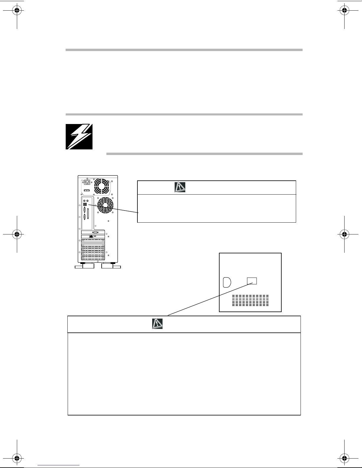
Labels
xv
T wo caution labels are af fixed Toshiba M500D serv er—one to the
rear of the server and the other on the inside of the side panel.
DANGER: Never remove the caution labels. If the labels are
illegible, consult your authorized service repair office or
sales office.
CAUTION
DANGER: Power supply poses hazards of electrical shock injury
to persons and damage to equipment. It should be removed and
replaced only by trained service technicians.
Inside of side panel
CAUTION
When you open the panel and work inside the server, observe the precautions below:
1 Turn off the server and disconnect the power cable to prevent injury by fans or an electric
shock.
2 Disconnect cables inside the server carefully to prevent your hand from hitting against the
inside of the server and being injured.
3 Add or remove expansion cards carefully to prevent your hands from being injured by their
edges.

xvi
Service options
Toshiba offers a full line of service options b uilt around its
warranty programs. See the warranty material included with the
server for registration information.
Maintenance contracts
Periodic maintenance and inspection is essential to keep the server
fully operational and assure its safe use. Toshiba recommends
purchasing a maintenance contract for this purpose.

xvii
Chapter
Make sure you hav e ev erything . . . . . . . . . . . . . . . . . . . . . . . . . . . . . . . . . . 1
Environmental considerations . . . . . . . . . . . . . . . . . . . . . . . . . . . . . . . . . . . 2
System overvie w . . . . . . . . . . . . . . . . . . . . . . . . . . . . . . . . . . . . . . . . . . . . . . 4
Hard disk drive (HDD) . . . . . . . . . . . . . . . . . . . . . . . . . . . . . . . . . . . . . . . . 11
Power supply . . . . . . . . . . . . . . . . . . . . . . . . . . . . . . . . . . . . . . . . . . . . . . . . 12
General maintenance . . . . . . . . . . . . . . . . . . . . . . . . . . . . . . . . . . . . . . . . . . 12
Ke yboard comfort . . . . . . . . . . . . . . . . . . . . . . . . . . . . . . . . . . . . . . . . . . . . 13
1

Getting Started
This chapter describes the Toshiba M500D server and the
environmental conditions in which it is designed to operate.
Make sure you have everything
Unpack the boxes and check the contents against the T oshiba
M500D Quick Start card provided with your system.
If the server contains optional devices, those components will be
listed on the content list and your purchase order . If an y items are
missing or damaged, notify your Toshiba representative
immediately .
1
Getting Started
2
Environmental considerations
Environmental considerations
Place the server on a level surface in a clean, dust-free, and wellventilated area free from:
Direct sunlight
❖
V ibration
❖
Liquids and corrosive chemicals
❖
CAUTION: If you spill liquid into the server, turn it off,
unplug it from the AC power source, and let it dry out
completely before turning it on again. If the server does not
operate correctly after you turn it back on, contact a Toshiba
authorized service provider.
Equipment that generates a strong electromagnetic field, such
❖
as large motors or speaker phones
Rapid changes in temperature or humidity and sources of
❖
temperature change such as air conditioner vents, fans, or
heaters
Extreme heat, cold, or humidity . Use the server within the
❖
following range of ambient conditions:
T emperature: 50° F to 95° F (10º C to 35º C)
Relative humidity: 30% to 80% RH (no condensation)
If the server is exposed to conditions that could result in
❖
condensation accumulating on the server’ s cabinet or it’s
internal components, wait one to two hours before operating
the server .
Getting Started
Environmental considerations
HINT: To inspect the server for moisture, remove the side
panel. For instructions on removing the side panel, see
“Removing the side panel” on page 25.
CAUTION: Condensation can corrode server components
and short-circuit it’ s electrical circuits if the unit is on. Av oid
exposing the server to condensation during use and storage.
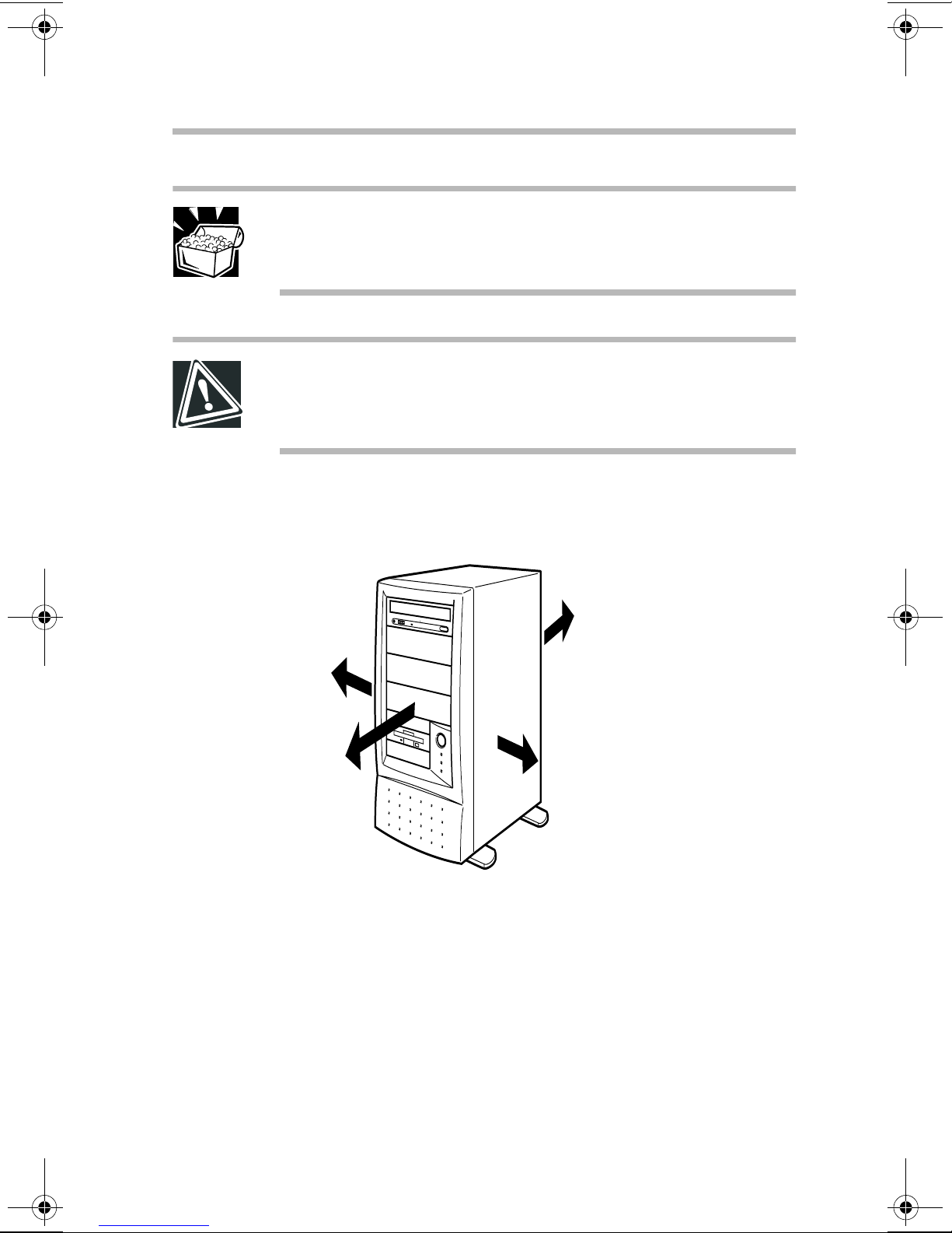
Allow suf ficient space around the serv er and other equipment to
allow for installation and maintenance.
3
2 in. (5 cm)
12 in. (30 cm)
Minimum installation clearances
8 in. (20 cm)
2 in. (5 cm)
Getting Started
4
System overview
System overview
The illustrations in this section identify the server’ s major
components, ports and hardware.
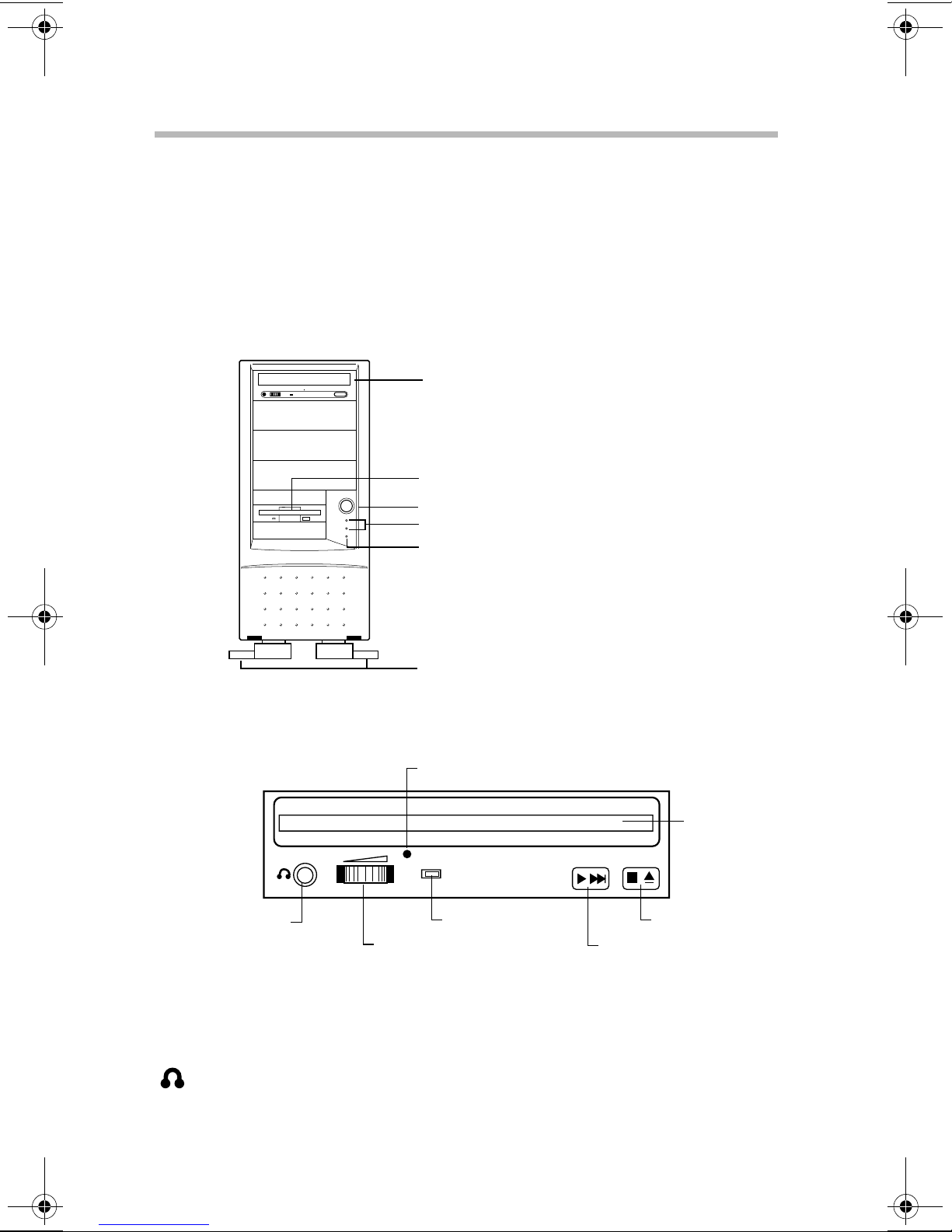
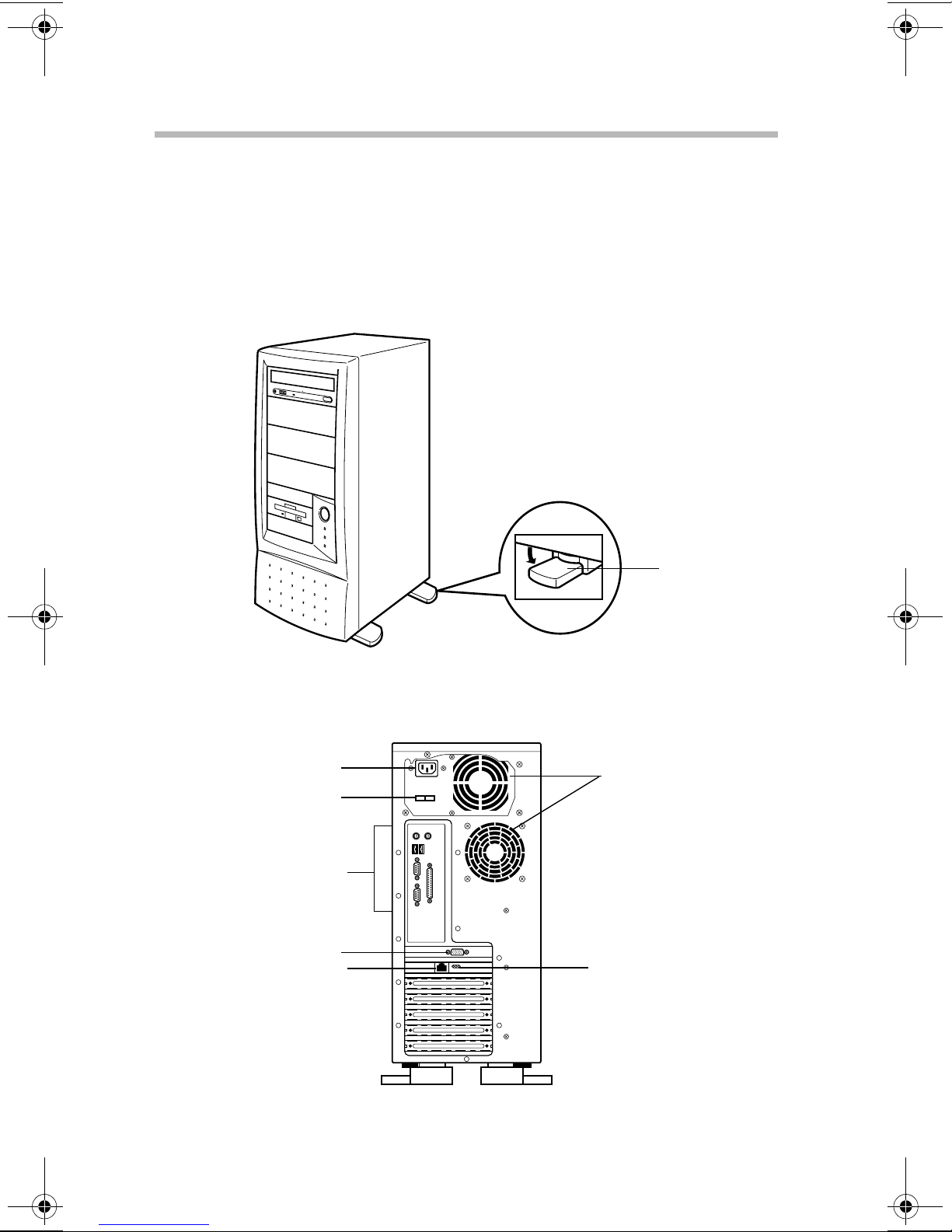
Front of the server
CD-ROM drive
Floppy disk drive
Power switch
Status indicators
Reset switch
Foot plates
CD-ROM drive
Manual eject pinhole
Disc tray
Headphone jack
Volume control dial
On/Busy light
Play/Skip button
The CD-ROM dri ve reads single-sided (3.15-in and 4.72-in) discs.
Disc tray - Holds compact discs in the CD-R OM dri ve.
Headphone jack - Allows you to connect a headset or earphones to
the CD-ROM dri v e.
Stop/Eject button
Getting Started
System overview
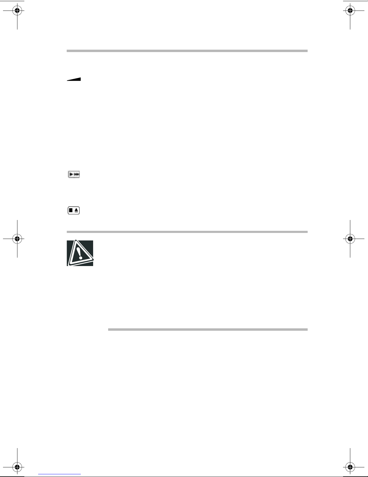
Volume control dial - Allows you to adjust the audio output
volume of the CD-R OM driv e.
Manual eject access pinhole - This pinhole provides access the a
manual eject button, allo wing you to manually release the disc tray
if it does not open when you press the Stop/Eject button. T o open
the disc tray manually , turn off the server and insert a slender
object, such as a straightened paper clip, into the pinhole.
On/Busy light - Illuminates when the CD-ROM dri v e is in use.
Play/Skip button - Pressing the Play/Skip button begins playback
of selected content. Pressing this button while a track is playing
advances the content to the track and resumes playback.
5
Stop/Eject button - Stops content playback. When content is not
playing, pressing this button either opens or closes the disc tray.
CAUTION: To avoid damaging the CD-ROM drive, never
manually open the disc tray while the server is on.
Never insert a pencil lead, plastic stick, or any other easily
breakable object into the manual eject button pinhole.
Never press the Stop/Eject button while the On/Busy light is
lit. Doing so could affect the system.
Never remove the compact disc from the CD-ROM drive
when the On/Busy light is lit.
When handling compact discs:
Hold the compact disc by the center and outer edge, taking
❖
care not to touch the surface.
Place the compact disc on the disc tray with the label side up.
❖
Keep the compact disc in its protectiv e case when not in use.
❖
A v oid e xposure to high temperature.
❖
Never bend or place hea vy objects on the compact disc.
❖
6
Getting Started
System overview
If a compact disc is dirty, clean it carefully with a soft dry
❖
cloth. Always use gentle strokes from the center of the disc
outward. Never wipe in a circular motion.
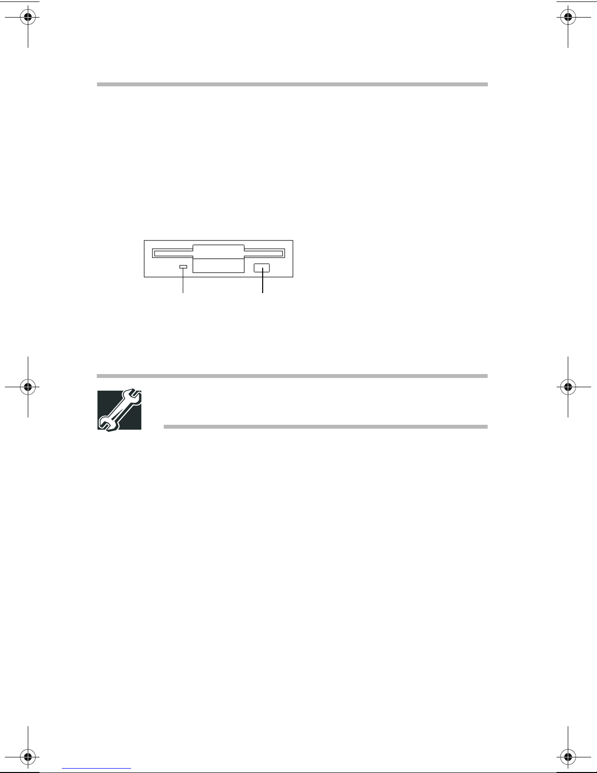
Floppy disk drive (FDD)
The drive reads 3.5-inch diskettes (1.44 MB/720 KB).
In-use light Eject button
In-use light - Glows while the diskette is being accessed.
Eject button - Releases the diskette from the driv e.
TECHNICAL NOTE: To prevent data loss, never press the
eject button while the in-use light is lit.
When handling diskettes:
Never open the shutter.
❖
A v oid touching the diskette’s magnetic surface.
❖
Keep diskettes a way from objects such as large motors or
❖
speaker phones that generate strong magnetic fields. Magnetic
fields may erase the data on the diskettes.
A v oid exposing diskettes to direct sunlight or to any source of
❖
heat.
Never place heavy objects on disk ettes.
❖
Store diskettes under the following ambient conditions:
❖
T emperature: 32° F to 127° F (0° C to 53°C)
Humidity: 8% to 90% RH
Getting Started
System overview
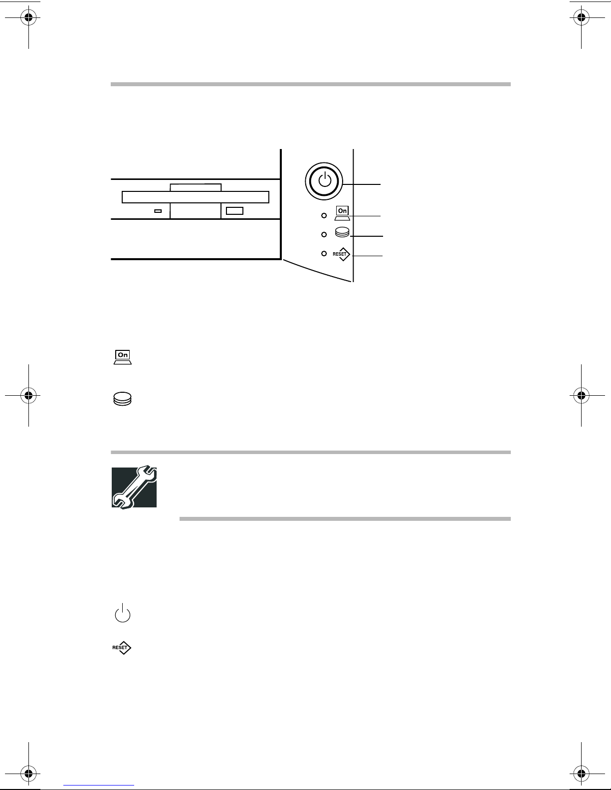
System indicator lights
Power button
Power light
Disk light
Reset button
Each system light provides information on the state of the server .
T ype of light State of light State of server
7
Power Off Not running
Green Running normally
Disk Off Disk not running
Flashing green Disk running
TECHNICAL NOTE: Never turn off the server or reset the
system while the disk light is lit. Data could be lost or
destroyed.
Operation switches
T y pe of bu tton Usage
Power Press to turn the server on or of f.
Reset Press to restart the server . Use a slender
object to press the button.
The procedures for turning the server on and off v ary depending
on the system. See “Turning on the server” on page 64.
8
Getting Started
System overview
Foot plates
For better stabilization, four foot plates are installed on the bottom
of the server. To stabilize the server , rotate the four foot plates out
to their extended position.
Back of the server
AC connector
115/230 VAC switch
I/O ports
Monitor port
Ethernet port
(optional on some models)
Foot plate
Cooling fans
Communication and
Link Speed lights
Getting Started
System overview
AC connector - Use this port to connect the A C po wer cable.
❖
See “Connecting the power cable” on page 63.
115/230 VAC switch - This switch allows you to choose the
❖
correct voltage for your geographic location. See “Connecting
the power cable” on page 63.
Cooling fans - These fans pre vent de vices in the serv er from
❖
overheating. The cooling fans are not user -replaceable. If a
cooling fan fails, contact your T oshiba authorized service
representative.
CAUTION: To ensure proper ventilation and avoid
overheating, keep the area around the cooling fans clear.
9
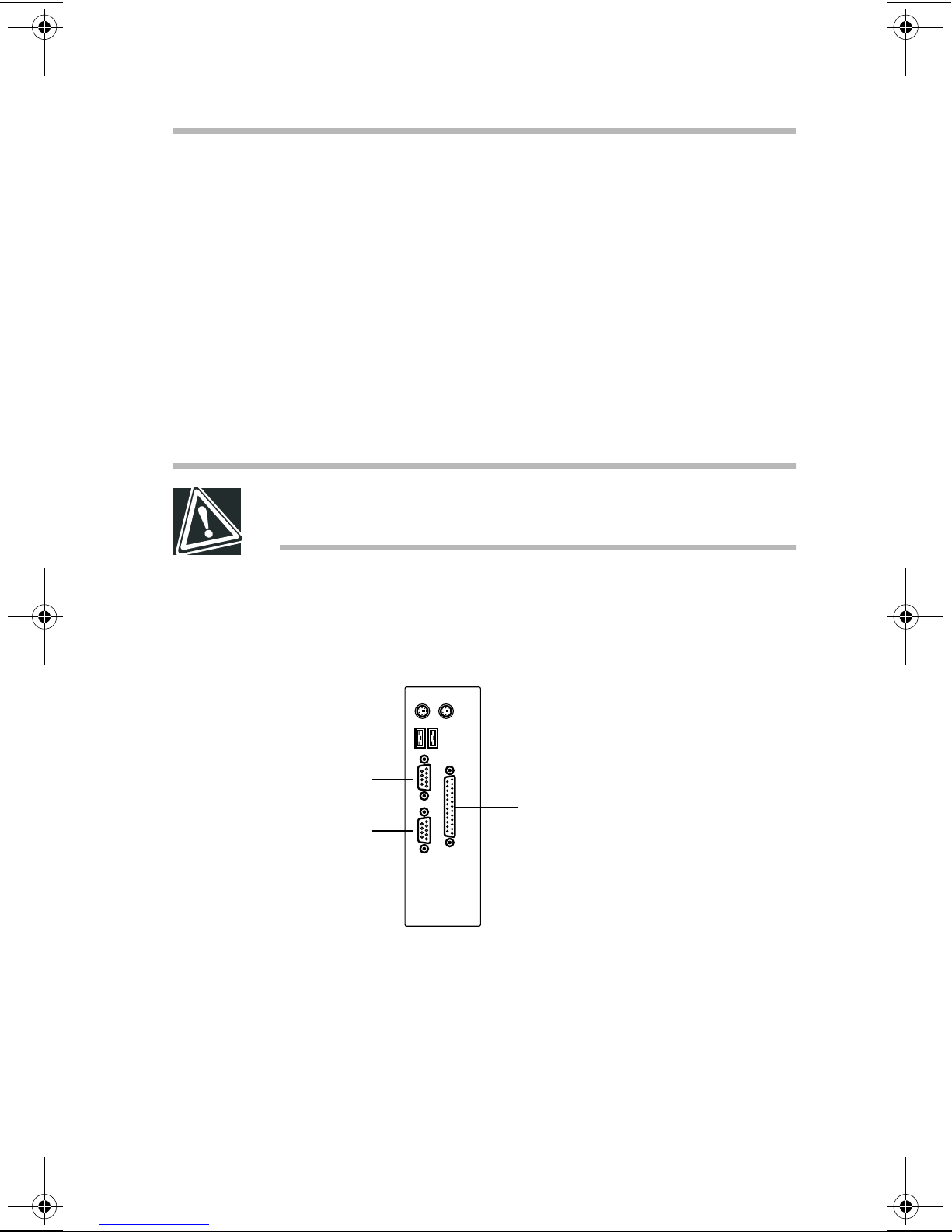
I/O ports - Use these ports to connect the PS/2 keyboard, P/S
❖
mouse, printer, and serial peripherals. See “Connecting
peripherals” on page 61.
Keyboard
*USB
Serial 2 (COM2)
Serial 1 (COM1)
Monitor port - Use this port to connect the monitor .
❖
Ethernet port - This port allows you to connect to a
❖
100BASE-TX or 10B ASE-T Ethernet
Mouse
Parallel
*Functional if supported
by installed operating system
®
LAN (optional on
some models).
10
Getting Started
System overview
Communication and speed lights - The Communication
❖
(ACT) and Link lights indicate the communication status.
On: Connected normally and waiting
Flashing: Communicating
Off: Network cable unconnected or connected
incorrectly
The Link Speed light (100M) indicates the communication
❖
speed.
On: Communication at 100 Mbps
Off: Communication at 10 Mbps
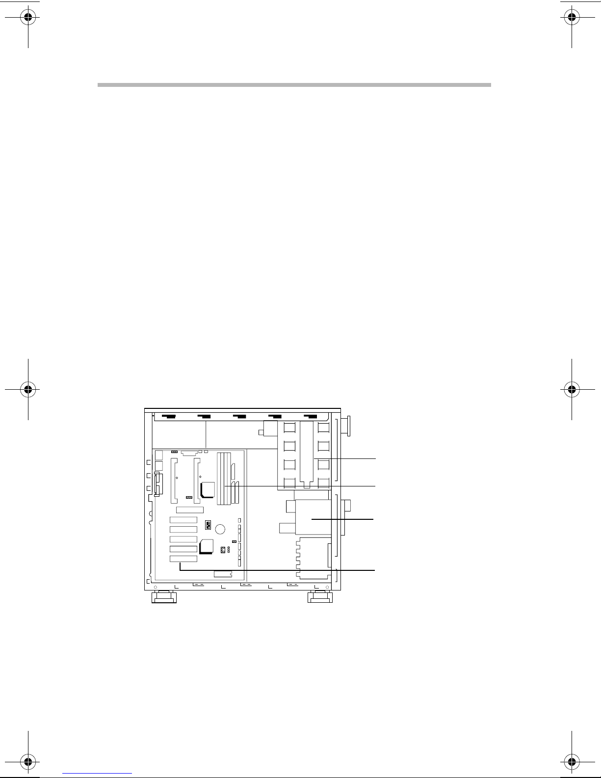
Inside the server
JP1
USB PS/2
CPU 1
CPU 2
COMA COMB
JP10
AGP
PCI5 PCI4 PCI3 PCI2 PCI1
5.25-inch device bay - This de vice bay has four slots which
❖
FAN2
PIIX4
FAN1
82443BX
SW
6BXD
BAT1
SB-LINK
FLOPPYIDE2
IDE1
11111111
PWR
SOFT
J12
JP12
PWR
SPRREST HD IR GN GD
5.25-inch device bay
Memory slots
3.5-inch device bay
(front accessible)
Expansion slots
are accessible from the front of the server (one has a CDROM dri ve installed). The serv er supports built-in SCSI
devic es.
Memory slots - The server has four memory slots that support
❖
128 MB and 256 MB modules. See “Adding memory” on
page 34 for more information.
3.5-inch device bay - This de vice bay has two slots which are
❖
accessible from the front of the server (one contains the
floppy disk driv e). In addition, the serv er has one internal 3.5inch device bay .
Expansion slots - The system board has 6 expansion slots—
❖
one AGP and fi v e 32-bit PCI slots. The PCI slots accept PCI
expansion cards and support PCI2.1 specifications.
Hard disk drive (HDD)
Getting Started
Hard disk drive (HDD)
11
The disk light flashes green while the disk driv e is reading or
writing data.
CAUTION: Installing or replacing the HDD requires special
skills and knowledge.Toshiba recommends that, instead of
replacing the hard disk drive yourself, you contact an
authorized service provider to do it for you. While the system
is running, an error in the course of installing or replacing it
could cause failures and destruction or loss of important
programs and data.
Avoid exposing the server to shock or vibration while the
power is on. Even if the light is off, the hard disk drive head
stays in the data area while the disk is spinning.
When the server is turned off, the hard disk drive head
automatically retracts and continues spinning. W ait 30 seconds for
the drive head to stop spinning before remo ving the hard disk
drive.
Getting Started
12
P ower supply
Power supply
The server has one po wer supply rated at 300 watts.
General maintenance
Care of the server
If the server is dusty , wipe it clean with a soft, dry cloth. If it is
❖
very dirty, wipe it lightly with a damp cloth.
A void e xposing the server to chemicals such as benzine, paint
❖
thinner and insecticide, which could damage or discolor the
case.
To prevent system malfunctions, a v oid exposing the serv er to
❖
shock or vibration.
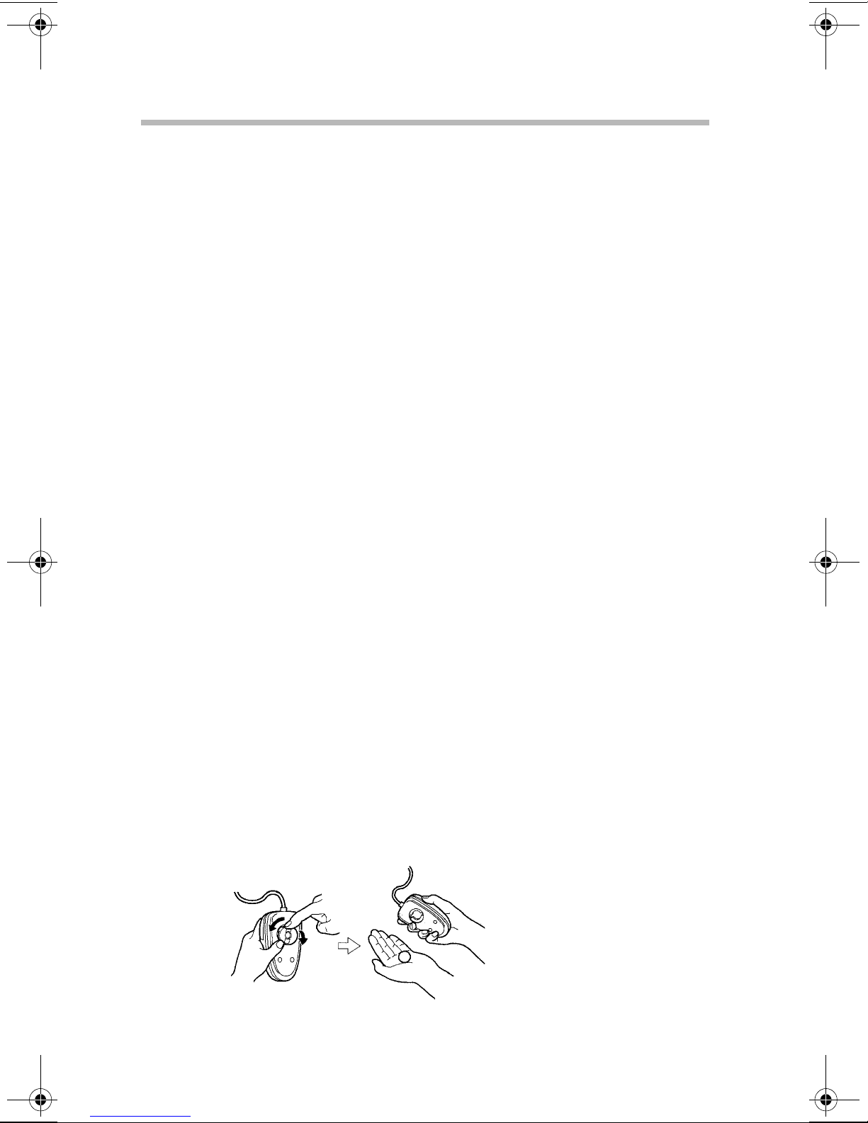
Care of the mouse
If the mouse is used for a long period of time, dust may adhere to
the ball, making the mouse pointer action sluggish or erratic.
Clean the mouse periodically:
Turn of f the serv er.
1
Rotate the cover on the bottom of the mouse in the direction
2
of the arrow (counterclockwise), remove the cov er , then
remove the ball.

Getting Started
Keyboard comfort
Using a dry cloth, remove any foreign matter adhering to the
3
rollers inside the mouse.
W a sh the ball with tap water or a neutral detergent.
4
Dry the ball and place it back in the mouse.
5
Position the cover on the bottom of the mouse and rotate it in
6
the opposite direction to the arrows (clockwise) until it clicks
13
into its locked position.
Care of the keyboard
If the keyboard is dusty, wipe it clean with a dry, soft cloth.
Keyboard comfort
You can work more comfortably and efficiently b y thoughtfully
organizing your work space. Dev eloping good work habits is the
best way to av oid strain and stress to your hands, back, neck and
eyes.

Getting Started
14
Ke yboar d comfort
CAUTION: Using the computer keyboard incorrectly may
result in discomfort and possible injury. If your hands,
wrists, and/or arms bother you while typing, stop using the
computer and rest. If the discomfort persists, consult a
physician.
Developing good work habits
The key to av oiding discomfort or injury from repetitive strain is to
vary your acti vities. If possible, schedule a v ariety of tasks into
your working day . Finding ways to break up the routine can
reduce stress and improve your ef f iciency.
Take recovery pauses from typing.
❖
Take short breaks to change position, stretch your muscles,
❖
and rest your eyes. A two or three minute break e v ery half
hour is more effecti ve than one long break after se veral hours.
Stretch spontaneously throughout the day to reduce tension.
❖
A v oid performing repetiti v e acti vities for long periods.
❖
Intersperse repetitive acti vities with other tasks.
T o reduce e ye strain, look away from the computer ev ery 15
❖
minutes or so, and focus your eyes on a distant object for 30
seconds.
Arranging your work area
Carefully planned placement of your computer and desktop tools
can help you avoid stress-related injuries and make working more
efficient. Adjusting the lighting can mak e it easier to see your
work and reduce eye strain.

Getting Started
Keyboard comfort
Place the keyboard on a flat surface, directly in front of you, at
❖
a comfortable distance. When you use the keyboard, your
arms and hands should be in a relaxed position with your
forearms parallel to the floor . You should be able to type
without twisting your body or neck.
Place the monitor so that its top is at eye le vel (lo wer for
❖
bifocal or progressiv es wearers).
Adjust the screen to avoid reflections and glare.
❖
Set your paper holder at the same distance as the screen. If
❖
possible, adjust the holder so that the paper is at the same
height as the screen.
15
Position the monitor so that sunlight or bright indoor lighting
❖
does not reflect off the screen. Use tinted windo ws or shades
to reduce glare.
A v oid placing the monitor in front of a bright light that could
❖
shine directly in your eyes.
If possible, use soft, indirect lighting in your computer work
❖
area.
Seating and posture
Correct postur e and computer placement

16
Getting Started
Ke yboar d comfort
When using the computer, sit comfortably . Proper seating is one of
the primary factors in reducing work strain.
Position your chair so that the keyboard is at or slightly belo w
❖
the level of your elbo w. You should be able to type
comfortably with your shoulders relaxed.
Your knees should be slightly higher than your hips. If
❖
necessary , use a foot rest to raise the le v el of your knees and
ease the pressure on the back of your thighs.
Adjust the back of your chair so that it supports the lower
❖
curve of your spine. If necessary, use a cushion to provide
extra back support.
Sit with your back straight so that your knees, hips and elbows
❖
approximately form 90-degrees angles when you work. Do
not slump forward or lean back too far.
Using your arms and wrists
Keep your wrists straight while typing. If necessary , adjust the
❖
keyboard and chair height to keep wrists straight.
A v oid resting on your wrists while typing.
❖
Use a light touch on the keys and mouse.
❖
A void bending, arching, or twisting your wrists. Keep them in
❖
a relaxed, neutral position while typing.
Exercise your hands, wrists and arms several times during the
❖
day to improve circulation.
Regular attention to your work habits can make your time at the
computer more productive.

Getting Started
Keyboard comfort
17

Chapter
Installing optional devices . . . . . . . . . . . . . . . . . . . . . . . . . . . . . . . . . . . . . . 19
Removing and installing the bezel and side panel . . . . . . . . . . . . . . . . . . 24
Adding a secondary CPU module . . . . . . . . . . . . . . . . . . . . . . . . . . . . . . . 27
Adding memory . . . . . . . . . . . . . . . . . . . . . . . . . . . . . . . . . . . . . . . . . . . . . . 34
Adding an IDE hard disk driv e . . . . . . . . . . . . . . . . . . . . . . . . . . . . . . . . . . 37
Starting the SCSI utility . . . . . . . . . . . . . . . . . . . . . . . . . . . . . . . . . . . . . . . 50
Adding SCSI I/O devices . . . . . . . . . . . . . . . . . . . . . . . . . . . . . . . . . . . . . . 55
Expansion cards . . . . . . . . . . . . . . . . . . . . . . . . . . . . . . . . . . . . . . . . . . . . . . 58
Connecting peripherals . . . . . . . . . . . . . . . . . . . . . . . . . . . . . . . . . . . . . . . . 61
System startup . . . . . . . . . . . . . . . . . . . . . . . . . . . . . . . . . . . . . . . . . . . . . . . 65
2

Connecting
Components
Installing optional devices
You should install all optional devices before setting up the server.
Before you start
Before installing an optional device, read the manuf acturer’s
❖
instructions and the installation instructions in this manual.
The procedures described in this chapter require specific
❖
technical knowledge and experience. If you hav e no
experience installing/removing optional de vices, or if the job
seems diff icult, consult your authorized service provider.
Toshiba assumes no liability for damages if you install and/or
remove optional de vices yourself.
DANGER: Never handle any electrical component that is not
described in this manual. Some parts carry high voltages
and are dangerous.To avoid electrical shock, shut down the
server and disconnect the power cable before performing
any server maintenance.
19

20
Connecting Components
Installing optional devices
HINT: Toshiba recommends using Toshiba-certified devices
or peripherals. Consult your authorized service repair office,
sales office, or log on to the Web site at
www.support.toshiba.com for recommended devices.
Selecting a workplace
Before performing server maintenance, select a place that
❖
does not have high humidity and is as free of dust and direct
sunlight as possible.
The ambient temperature and humidity should range between
❖
50°F to 95°F (10°C to 35°C) and 30% to 80% RH. A v oid
exposing the server to sharp temperature fluctuations that
could cause condensation.
Never install or remov e de vices in a static-inducing
❖
environment (on a carpet, for e xample). Electronic devices
can fail if they are e xposed to electrostatic discharge (ESD).
Working safely
Make sure you read and understand the instructions and
❖
precautions in this guide before performing server
maintenance.
Perform the steps in each procedure in the order written.
❖
Before disconnecting any cables, check their positions to
❖
make sure you reconnect them correctly.
Check cable connectors for broken or bent pins. If a cable
❖
connector has screws, tighten the scre ws f inger-tight when
securing the cable.
If a failure occurs, consult your authorized service provider .
❖
Connecting Components
Installing optional devices
WARNING: To avoid electrical shock, never operate the
server with the side panel removed.
CAUTION: Internal server components can be seriously
damaged by static electricity. Wear a wrist or heel ground
cable to discharge static electricity carried on your body. If
such equipment is not available, touch a grounded metal
object to discharge static electricity before working on
sensitive electronic components.
Once you remove a device from its antistatic package, if necessary, place the antistatic package and the device on a flat,
grounded surface. Store the antistatic package.
21
To prevent static build-up, never drag the server when
moving it.
Maintenance overview
WARNING: Never disassemble the server more than
described in this manual. Failure to observe this precaution
could result in electric shock, cause a system fault, or void
your warranty.
When performing maintenance on the server , follow these general
steps.
Turn of f all peripherals connected to the serv er.
1
Turn of f the server.
2
Unplug all power cables from their A C outlets. Disconnect all
3
cables connected to the back of the server .

22
Connecting Components
Installing optional devices
To access the inside of the server , remov e the bezel and side
4
cover. For instructions, see “Removing and installing the
bezel and side panel” on page 24.
Perform any required maintenance.
5
CAUTION: Make sure that components handled during
system maintenance are properly installed and connections
are securely seated. Also check that no tools or hardware
items are left inside the server.
HINT: The procedures for removing and installing hard disk
drives depend on the drive type—IDE or SCSI. Be sure to
check the drive’s specifications before attempting to install
or remove a drive.
Reinstall the side panel and bezel. “Removing and installing
6
the bezel and side panel” on page 24.
Reconnect all signal and power cables.
7
Turn on the serv er and run an y required system checks.
8
Some optional devices require you to reconf igure the server’s
software, change jumper , and/or DIP switch settings before
the device can be used.
In addition to the instructions in this chapter, refer to the
manufacturer’ s user manuals for the de vices you are installing/
removing.

Connecting Components
Installing optional devices
T oshiba supplied hardware items
The following table lists the hardware item that Toshiba provides
with your server.
T ype Usage
Screw A (SAE) Installing HDDs on the driv e carrier
Installing SCSI HDDs and adapter plate in the 5.25-inch device
bay Installing expansion cards
23
Screw B
(metric)
Screw C (SAE) Installing HDDs or SCSI devices in the 5.25-inch de vice bay
Stud Reserved parts. Usually, they are not used.
Rail Used for in stalling HDDs or SCSI de vices in the 5.25-inch
Installing units except HDDs (MO or D AT) on the drive carrier
or the rails
Installing the drive carrier on the serv er
When installing devices, use the accessories that came with the
devices. Use this scre w to replace missing scre ws.
device bay
When performing server maintenance:
Use the appropriate type and size of screwdri ver. A
❖
screwdri ver that is too small or too lar ge can damage the
screw head. Check the scre w type before use.
Be careful not to lose any removed scre ws or drop them inside
❖
the equipment.
Use the same type of screws when installing de vices.
❖

Connecting Components
24
Removing and installing the bezel and side panel
Removing and installing the bezel and side
panel
To access the CPU slots, memory module slots, expansion slots,
and device bays, you need to remove both the bezel and the side
panel.
Bezel
Removing the bezel
Grasp the latch at the bottom edge of the bezel.
1
Squeeze the latch, then pull it toward the front of the serv er to
2
release the lower edge of the bezel from the server chassis.
Side panel
Removing the bezel
Rotate and lift the bezel away from the serv er.
3

Removing and installing the bezel and side panel
CAUTION: Never use force to remove the bezel. Using force
may break the bezel’s hooks.
Removing the side panel
Remove the bezel as described in the pre vious section.
1
Remove the scre w securing the side panel to the server.
2
Connecting Components
25
Removing the side panel scre w
Slide the side panel toward the front of the server , then lift and
3
remove the panel.
Removing the side panel

Connecting Components
26
Removing and installing the bezel and side panel
Installing the side panel
Position the side panel on the server chassis, then slide the
1
panel to the back of the server until it locks in place.
Installing the side panel
Secure the side panel to the server with a screw.
2
Installing the bezel
Align the upper hooks on the bezel with the slots in the server
1
chassis.
Attaching the upper bezel hooks

Connecting Components
Adding a secondary CPU module
Rotate the bezel toward the serv er chassis making sure the
2
lower bezel hooks align with the slots in the server chassis.
Press the lower edge of the bezel against the server chassis
3
until it locks into place.
Adding a secondary CPU module
TECHNICAL NOTE: Toshiba M500D servers support dualCPU configurations. All CPU modules used in multi-CPU
server configurations must operate at the same clock speed
(frequency) and have the same cache size.
27
If the server is in use, shut it do wn and unplug the po wer
1
cable.
WARNING: Installing a CPU module with the power on could
result in electrical shock, and damage the CPU and/or the
server.
To avoid burn injuries, never install a CPU module
immediately after turning off the server. Wait until the heat
around the CPU slot dissipates.
CAUTION: CPU modules can be seriously damaged by static
electricity. Wear a wrist or heel ground cable to discharge
static electricity carried on your body. If such equipment is
not available, touch a grounded metal object to discharge
static electricity before working on sensitive electronic
components.
Remove the bezel and side panel. F or instructions, see
1
“Removing and installing the bezel and side panel” on
page 24.

28
Connecting Components
Adding a secondary CPU module
Press the tabs on the secondary (right) CPU slot outward to
2
release the termination board, then lift and remove the
termination board.
Termination board
Secondary (right) CPU slot
Primary (left) CPU slot
Removing the termination board
HINT: The primary CPU module resides in the Primary (left)
CPU slot. The secondary CPU module installs in the right
CPU slot. Servers shipped with a single CPU module have a
CPU termination board installed in the secondary CPU slot.
Position the new CPU module in the secondary (right) CPU
3
slot.
Using equal pressure, press both ends of the CPU module into
4
the CPU slot until you hear a click—indicating that the CPU
module is securely locked into place.
CAUTION: To avoid deforming the CPU module’s heatsink,
avoid applying pressure to the heatsink while installing the
CPU module.

Connecting Components
Adding a secondary CPU module
Connect the fan cable attached to the secondary CPU module
5
to connector FAN PWR2 on the system board.
CPU module
CPU fan cable
Secondary (right) CPU slot
29
FAN PWR2
FAN PWR1
Installing the new CPU module
Short pins 2 and 3 on jumper JP10 to configure the server to
6
auto-detect the processing speed of the CPU module.
1
CPU2
2
3
PIIX4
JP10
CPU1
82443BX
6BXD
ON
OFF
1 2 3 4
Short pins
2 and 3
JP10
System board JP10 jumper setting
SW

30
Connecting Components
Adding a secondary CPU module
Reinstall he side panel and bezel. For instructions, see
7
“Removing and installing the bezel and side panel” on
page 24.
Plug in the power cable, then press the Po wer b utton to turn
8
on the server.
Del
During system boot up, press the
9
Setup Utility .
In the Chipset features Setup of the System Setup Utility, set
10
the following parameters:
CPU2 Fan Control -
❖
CPU2 Fan Fail Alarm -
❖
Enabled
Enabled
key to start the System
Save the changed values, then restart the server.
11
Follow the on-screen messages to confirm that the serv er
12
recognizes the installed CPU module.
HINT: When the server detects both CPU modules correctly,
two lines of CPU information appear on screen.
Reinstall the operating system.
13
Replacing a CPU module
TECHNICAL NOTE: All CPU modules used in multi-CPU
server configurations must operate at the same clock speed
(frequency) and have the same cache size.

Connecting Components
Adding a secondary CPU module
If the server is in use, shut it do wn and unplug the po wer
1
cable.
WARNING: Installing a CPU module with the power on could
result in electrical shock, and damage the CPU and/or
server.
To avoid burn injuries, never install a CPU module
immediately after turning off the server. Wait until the heat
around the CPU slot dissipates.
CAUTION: CPU modules can be seriously damaged by static
electricity. Wear a wrist or heel ground cable to discharge
static electricity carried on your body. If such equipment is
not available, touch a grounded metal object to discharge
static electricity before working on sensitive electronic
components.
31
Remove the bezel and side panel. F or instructions, see
1
“Removing and installing the bezel and side panel” on
page 24.
Disconnect the fan cable attached to the CPU module you are
2
going to remove from the system board.
Press the tabs on the CPU slot outward to release the CPU
3
module, then lift and remove the module.

32
Connecting Components
Adding a secondary CPU module
CPU fan cable
Removing the CPU module
Position the new CPU module in the CPU slot.
4
CPU module
FAN PWR1
Installing the new CPU module
Using equal pressure, press both ends of the new CPU
5
module into the CPU slot until you hear a click—indicating
that the module is securely locked into place.
FAN PWR2

Connecting Components
Adding a secondary CPU module
CAUTION: To avoid deforming the CPU module’s heatsink,
don’t apply pressure to the heatsink while installing the CPU
module.
Connect the fan cable attached to the new CPU module to the
6
appropriate connector system board.
If you are replacing the primary CPU module, connect
❖
the fan cable to connector FAN PRW1 on the system
board.
If you are replacing the secondary CPU module, connect
❖
the fan cable to connector FAN PRW2 on the system
33
board.
HINT: The primary CPU module resides in the left CPU slot.
The secondary CPU module installs in the right CPU slot.
Reinstall the side panel and bezel. For instructions, see
7
“Removing and installing the bezel and side panel” on
page 24.
Plug in the power cable, then press the Po wer button to turn
8
on the server .
Follow the on-screen messages to confirm that the server
9
recognizes the installed CPU module.
HINT: When the server detects both CPU modules correctly,
two lines of CPU information appear on screen.

Connecting Components
34
Adding memory
Adding memory
The server contains four memory slots. You can install one Dual
In-line Memory Module (DIMM) with Error-Correcting Code
(ECC) in each slot—64 MB, 128 MB and 256 MB modules are
av ailable. When installing memory modules, use one of the
module combinations listed in the following table.
Memory slot
64 64
64 64 128
64 64 64 192
64 64 64 64 256
64 128 192
64 128 128 320
64 128 128 128 448
64 256 320
64 256 256 576
64 256 256 256 832
128 128
128 128 256
Total memory
(MB)BANK 0 B ANK 1 B ANK 2 B ANK 3
128 128 128 384
128 128 128 128 512
128 256 384
128 256 256 640
128 256 256 256 896
256 256
256 256 512
256 256 256 768
256 256 256 256 1024

Connecting Components
Adding memory
35
JP1
USB PS/2
CPU 2
COMA COMB
AGP
PCI5 PCI4 PCI3 PCI2 PCI1
JP10
CPU 1
FAN2
FAN1
82443BX
PIIX4
Bank 0
Bank 1
FLOPPYIDE2
Bank 2
IDE1
6BXD
SW
SB-LINK
11111111
PWR
SOFT
BAT1
J12
JP12
PWR
SPRREST HD IR GN GD
Bank 3
Memory bank locations
WARNING: Never install or remove memory modules
immediately after turning off the server. To avoid burn
injuries, wait for the heat around the memory modules to
dissipate.
TECHNICAL NOTE: Memory modules can be seriously
damaged by static electricity. Wear a wrist or heel ground
cable to discharge static electricity carried on your body. If
such equipment is not available, touch a grounded metal
object to discharge static electricity before working on
sensitive electronic components.
Installing a memory module
Remove the bezel and side panel. F or instructions, see
1
“Removing and installing the bezel and side panel” on
page 24.

36
Connecting Components
Adding memory
Align the notch in the memory module with the notch in the
2
connector, then carefully press do wn on the module until the
latches on the connector lock the memory module into place.
CAUTION: Installing a memory module the wrong way could
damage the memory module and/or the memory slot.
Inserting the memory module
Reinstall the side panel and bezel. For instructions, see
3
“Removing and installing the bezel and side panel” on
page 24.
Removing a memory module
Remove the bezel and side panel. F or instructions, see
1
“Removing and installing the bezel and side panel” on
page 24.
TECHNICAL NOTE: Memory modules can be seriously
damaged by static electricity. Wear a wrist or heel ground
cable to discharge static electricity carried on your body. If
such equipment is not available, touch a grounded metal
object to discharge static electricity before working on
sensitive electronic components.

Connecting Components
Adding an IDE hard disk drive
Rotate the levers securing the memory module away from the
2
module, then lift the memory module from the connector .
HINT: Handle the module with care. The memory module
may pop out when you open the latches.
Reinstall the side panel and bezel. For instructions, see
3
“Removing and installing the bezel and side panel” on
page 24.
Adding an IDE hard disk drive
37
Specific technical knowledge is required to install or replace a
hard disk drive (HDD). If you are not sure ho w to proceed,
Toshiba recommends that you ask your authorized service
provider to install or replace HDDs.
CAUTION: Take care when handling hard disk drives. Avoid
subjecting the hard disk drive to shock or vibration. The disk
could be damaged and its data destroyed.
IDE interface
You can connect up to two hard disk drives to the primary IDE
interface on the server’ s system board. The first hard disk dri v e is
the assigned “primary” or “master” and the second drive is the
“secondary” or “slave.”
In the T oshiba M500D, the primary hard disk drive is connected as
the master drive the primary IDE interface and the CD-R OM drive
is connected as the master drive on the secondary IDE interface.

38
Connecting Components
Adding an IDE hard disk drive
USB PS/2
COMA COMB
PCI5 PCI4 PCI3 PCI2 PCI1
JP1
CPU 2
CPU 1
FAN2
FAN1
FLOPPYIDE2
Primary IDE interface
JP10
AGP
82443BX
6BXD
SW
PIIX4
BAT1
SB-LINK
JP12
IDE1
Secondary IDE interface
11111111
PWR
SOFT
J12
PWR
SPRREST HD IR GN GD
IDE interface locations on the system board
Drive ID jumper setting for IDE HDDs
To connect an additional HDD to the IDE interface, you must set
each drive as either master or slav e. The settings for Fujitsu and
Western Digital hard disk drives are sho wn belo w.
9-pin drive jumper settings
9 7 5 3 1
9 7 5 3 1
Single & Dual (Master)
(Standard installation)
8 6 4 2
Dual (Slave)
8 6 4 2
40-pin IDE
connector
Jumper shunt
Jumper block
Power connector
Drive ID jumper setting for Fujitsu IDE hard disk drives

Connecting Components
Adding an IDE hard disk drive
10-pin drive J8 jumper settings
9 7 5 3 1
10 8 6 4 2
9 7 5 3 1
10 8 6 4 2
Single(Standard installation)
Dual (Master)
39
9 7 5 3 1
10 8 6 4 2
40-pin IDE
connector
Jumper shunt
Dual (Slave)
J8 Jumper block
Power connector
Drive ID jumper setting for Western Digital IDE hard disk drives
When adding IDE devices, set the de vices according to the
following table:
T o add a second (sla ve) de vice to the secondary IDE interface you
will need to purchase a new cable with an additional connector for
connecting the slave de vice.
Primary IDE interface Secondary IDE interface
Master Slave Master
HDD
connected.
First additional
HDD
CD-ROM dri v e
connected.
connected.
Slave
Second
additional HDD
connected.
Installing IDE HDDs
Remove the bezel and side panel. F or instructions, see
1
“Removing and installing the bezel and side panel” on
page 24.
Disconnect the power and signal cables from the hard disk
2
and floppy disk drives.
Remove the two scre ws securing the driv e carrier.
3

40
Connecting Components
Adding an IDE hard disk drive
Press the latches on the sides of the driv e carrier, then slide the
4
carrier out of the server chassis.
CAUTION: When removing the drive carrier, be careful not to
tangle system cables or touch the memory board.
Removing the drive carrier
Remove the 3.5-inch shield co ver from the dri v e carrier and
5
store it in a secure place.
Removing the drive shield
Loosen the eight screws that secure the FDD and HDD to the
6
drive carrier. There are four screws on each side.
Slave HDD
Scre w locations on the drive carrier
Master HDD

Connecting Components
Adding an IDE hard disk drive
Install the additional HDD in the driv e carrier and secure it
7
with two screws. Use “Scre w A” listed in “Toshiba supplied
hardware items” on page 23.
CAUTION: To prevent damage to the HDD or the data it
contains, avoid subjecting the drive to shock or vibration.
41
Rails
Placing a HDD into the drive carrier
Tighten the eight scre ws loosened in step 5.
8
Position the drive carrier into the server and secure it with two
9
screws. Insert the dri ve carrier so that the rails on the upper
side of the carrier latch to the ones in the server . Push the drive
carrier in until you hear a click—indicating that carrier is
locked in place.
Inserting the drive carrier into the server

42
Connecting Components
Adding an IDE hard disk drive
Reconnect the power and signal cables to the hard disk and
10
floppy disk drives.
Reinstall the side panel and bezel. For instructions, see
11
“Removing and installing the bezel and side panel” on
page 24.
Removing IDE HDDs
Remove the bezel and side panel. For instructions, see
1
“Removing and installing the bezel and side panel” on
page 24.
Remove the po wer and signal cable from the hard disk and
2
floppy disk drives.
Remove the two scre ws securing the driv e carrier.
3
Press the latches on the sides of the driv e carrier, then slide the
4
carrier out of the server chassis.
CAUTION: When removing the drive carrier, be careful not to
tangle system cables or touch the memory board.
Remove the two scre ws securing the hard disk driv e to the
5
drive carrier , then slide the dri v e from the carrier. Save the
screws for future use.
Install the 3.5-inch shield cover.
6
Insert the drive carrier in the serv er chassis and secure it with
7
two screws.
Connect the power and signal cables to the floppy disk dri v e
8
and any remaining hard disk dri ve.
Reinstall the side panel and bezel. For instructions, see
9
“Removing and installing the bezel and side panel” on
page 24.

Connecting Components
Using System Setup after installing an IDE HDD
Using System Setup after installing an IDE
HDD
To add a hard disk driv e when the manufacturer’s installation
software is not av ailable, perform the follo wing to conf igure the
system to recognize the new dri ve.
Del
Turn on the server and press
1
The BIOS SETUP display appears.
Select
2
If
3
to “Auto.”
STANDARD CMOS SETUP
T ype of Primary Sla ve
.
and press
is “None,” press the
Enter
.
+
key to set it
43
Press
4
Select
5
Press
6
The settings are saved and the server restarts.
Click
7
then
The Disk Administrator screen appears.
The new disk should be labeled “Disk x.” It should appear in
the last line and have no partitions. Refer to the Help files and
other user manuals for complete details on how to set up
partitions and format the driv e.
To partition and format the new disk, continue.
Click on the new disk’s area.
8
Esc
.
Enter
SAVE & EXIT SETUP
Y
, then
Start, Programs, Administrative tools (Common),
Disk administrator
Enter
.
.
and press
.
The disk’ s border highlights.
From the menu bar, select
9
you are sure of the results (see Help).
Follow the screen prompts to set up your disk en vironment.
10
Partition
, then
Create
. Click
Yes
if

44
Connecting Components
Adding a SCSI hard disk drive
After the partition is established, go to the menu bar and select
11
Partition
Follow the screen prompts to conf irm the setup.
12
The disk partition is created.
When the partition is completed, go to the menu bar and
13
select
From the Format page, make the proper selections for your
14
environment, then click
Follow the screen prompts to complete this process, then Exit
15
the utility .
The new disk is no w ready for use.
, then
Tools
Commit Changes Now
, then
Format
.
Start
.
Adding a SCSI hard disk drive
Specific technical kno wledge is required to install or replace a
.
hard disk drive (HDD). If you are not sure ho w to proceed,
Toshiba recommends that you ask your authorized service
provider to install or replace HDDs.
CAUTION: Take care when handling hard disk drives. Avoid
subjecting the hard disk drive to shock or vibration. The disk
could be damaged and its data destroyed.

SCSI configuration
SCSI installation guidelines
When installing SCSI HDDs, start at the bottom of the 3.5-inch
device bay and w ork up to the top of the 5.25-inch de vice bay.
Connecting Components
Adding a SCSI hard disk drive
45
JP1
USB PS/2
COMA COMB
PCI5 PCI4 PCI3 PCI2 PCI1
CPU 2
FAN2
FAN1
PIIX4
82443BX
SW
6BXD
BAT1
SB-LINK
FLOPPYIDE2
IDE1
11111111
PWR
SOFT
J12
JP12
PWR
SPRREST HD IR GN GD
CPU 1
JP10
AGP
SCSI HDD 3 (SCSI-ID = 3)
SCSI HDD 2 (SCSI-ID = 2)
SCSI HDD 1 (SCSI-ID = 1)
SCSI HDD 0 (SCSI-ID = 0)
SCSI HDD installation order
Jumper settings for SCSI HDDs
To connect a hard disk driv e to the SCSI-chain, you must set the
jumper for each driv e according to its position in the chain.
Locate the option jumper blocks on the SCSI driv e.
1
C
o
n
n
e
c
t
o
r
Location of option jumper blocks (top view)
J6
J4
Position #A
Option Jumper Block J-6
Position #G
Position #1
Option Jumper Block J-4
Position #12

46
Connecting Components
Adding a SCSI hard disk drive
Set the jumpers according to your particular configuration.
2
Option Jumper block J-6Option Jumper block J-4
SCSI Bus
GroundGroundLED Anode Open
12 11 10 9 8 7 6 5 4 3 2 1
LED Cathod
Disable SCSI Parity Check
Delay Start 6/12
Enable Auto Start Delay
*80 pin models do not have Option Jumper Block J-6
Setting the jumpers
0123
SCSI ID Bits
Enable Auto Spin Up
Force SE Mode
Disable Unit Attention
Enable TI-SDTR/WDTR
SCSI ID 0
SCSI ID 1
SCSI ID 2
SCSI ID 3
GFEDCBA
ReservedOpen
Enable T erminator
Power Supply
(Default jumper setting)
SCSI ID Settings
Short
Installing SCSI HDDs
T o install a SCSI hard disk dri ve (SCSI ID 0 and 1) in the 3.5-inch
device bay:
Set the SCSI ID for the hard disk dri ve. F or instructions, see
1
“Jumper settings for SCSI HDDs” on page 45.
Follow the instructions in “Installing IDE HDDs” on page 39.
2
To install a SCSI HDD (SCSI ID 2 and 3) in a 5.25-inch de vice
bay:
Remove the bezel and side panel. For instructions, see
1
“Removing and installing the bezel and side panel” on
page 24.

Connecting Components
Adding a SCSI hard disk drive
Set the SCSI-ID for the hard disk drive. For instructions, see
2
“Jumper settings for SCSI HDDs” on page 45.
Position the rails on the SCSI hard disk drive and secure them
3
with four screws.
Remove the scre ws securing the 5.25-inch shield co ve r and
4
store the cover in a safe place.
47
Removing the shield
Insert the SCSI HDD into the slot and secure it with two
5
screws.
Inserting the SCSI hard disk drive
Connect the power and SCSI cable to the SCSI HDD.
6

48
Connecting Components
Adding a SCSI hard disk drive
Connect the SCSI cable to the SCSI adapter.
7
SCSI cable
Connecting the SCSI cables
Remove the blank panel from the slot in the bezel where the
8
SCSI hard disk drive will reside and store it for possible reuse.
Removing the blank panel
Reinstall the side panel and bezel. For instructions, see
9
“Removing and installing the bezel and side panel” on
page 24.

Removing SCSI HDDs
To avoid equipment damage, review the precautions
described in “Before you start” on page 19 before removing
a SCSI device.
To remove a SCSI hard disk driv e from a 3.5-inch device bay,
follow the instructions in “Removing IDE HDDs” on page 42.
To remove a SCSI hard disk driv e from a 5.25-inch device bay:
Remove the bezel and side panel. F or instructions, see
1
“Removing and installing the bezel and side panel” on
Connecting Components
Adding a SCSI hard disk drive
49
page 24.
Remove the two scre ws that secure the SCSI driv e and metal
2
fittings, then partially extract the SCSI dri v e.
Disconnect the power cable and the SCSI cable from the
3
driv e.
Remove the SCSI HDD.
4
Install the shield cover and secure it with screws.
5
Install the blank panel in the empty slot in the bezel.
6
Reinstall the side panel and bezel. For instructions, see
7
“Removing and installing the bezel and side panel” on
page 24.
Connecting Components
50
Adding a SCSI hard disk drive
RAID configuration
When using a RAID configuration in the Toshiba M500D server,
follow the procedures sho wn in “SCSI configuration” on page 45.
Installing the RAID card
To install a RAID card, see “Installing expansion cards” on
page 59.
Setting up the RAID card
Refer to the user’s guide that came with the RAID card.
Starting the SCSI utility
When you start or reboot the server , the initialization screen of the
built-in SCSI BIOS appears.
Adaptec AHA 2940U2B SCSI BIOS vX.XX
(c) 1998 Adaptec, Inc. All Rights Reserved.
Press <Ctrl><A> For SCSISelect(TM) Utility! >>>
SCSI ID: 0 IBM XXXXX
SCSI BIOS initialization screen
When the settings are correct, the names and SCSI IDs of the
SCSI devices connected to the b uilt-in SCSI controller appear .
To start the utility , simultaneously press
during system boot.
ULTRA2-LVD
Ctrl
+ A, when prompted

Connecting Components
Adding a SCSI hard disk drive
Menu composition
When you start the SCSI utility , the follo wing Adaptec
SCSISelect
AHA-2940U2B at Bus=xxh Device=xxh.
Would you like to configure the host adapter,
or run the SCSI disk utilities? Select the
option and press<Enter>. Press <F5> to switch between
color and monochrome mode.
Arrow Keys to move cursor, <Enter> to select option, <Esc> to exit (*=default)
®
option screen appears:
Adaptec AHA 2940U2B < SCSISelect(TM)>Utility vX.XX
Bus:Device:Channel
00:0C:A
00:OC:B
OPTION
Configure/View Host Adapter Setting
SCSI Disk Utilities
Adaptec SCSISelect option screen
Basic SCSI utility operations
51
®
Use the following k eys to perform basic SCSI utility operations:
Esc Return to the preceding screen
Enter Select an item
↑
↓
Return to the preceding item
Proceed to the next item
SCSI disk utility operating procedures
To set up the utility:
↑
Use the up arrow (
1
item you wish to change.
Press
2
Enter
to select the item.
) and down arro w (↓) keys to highlight the
The selected menu or submenu appears.
Make your changes.
3
After setting all the necessary values, sa ve the data.
4
Press
5
Esc
a few times and follo w the on-screen instructions.

52
Connecting Components
Adding a SCSI hard disk drive
Device configuration (Configure/View Host Adapter
Setting)
To change the settings of a SCSI device or SCSI controller , f irst
select the SCSI controller, then select
“Configure/View Host
Adapter Setting.”
The table below lists the conf iguration parameters with their
default values and descriptions.
Item Parameter/Setting Description
Host Adapter
SCSI ID
SCSI Parity
Checking
Host Adapter SCSI T ermination:
7 Selects the SCSI host
adapter’ s SCSI ID.
Don’t chang e this setting
Enabled When enabled, the host
adapter uses SCSI parity
checking to verify the
accuracy of data transfer on
the SCSI bus.
Sets the SCSI bus termination.
Enabled
Don’t cha nge this setting
Boot Device
Options
Selects the device which starts
up the system. When you
select this item, the following
options appear:
Boot CSCSI ID: 0 Selects the SCSI ID of the
device which starts the system.
Don’t cha nge this setting .
Boot LUN Number: 0 Selects the LUN of the device
which starts the system.
Don’t cha nge this setting .

Connecting Components
Adding a SCSI hard disk drive
Item Parameter/Setting Description
53
SCSI Device
Configuration
Initiate Sync
Negotiation: Yes
Initiate Wide
Negotiation: Yes
Sync Transfer Rate
(MD/Sec.): 80.0
Enable Disconnection:
Yes
For detailed settings of each
SCSI device (SCSI ID). When
you select this item, the
following options appear:
When this option is set to Yes,
the adapter initiates wide
negotiation with each 16-bit
SCSI device.
Sets the maximum
synchronized transfer rate of
the on-board SCSI controller .
When this option is set to Yes,
a SCSI device can disconnect
temporarily from the bus,
while the host adapter
continues to do other bus
operations.
Send Start Unit
Command: Yes
BIOS Multiple LUN
Support: No
Include in BIOS Scan:
Yes
Controls whether the SCSI
Start Unit Command is sent to
the SCSI device.
Controls whether the BIOS
supports multiple logical units.
Controls whether the SCSI
device is included in the BIOS
scan.
Connecting Components
54
Item Parameter/Setting Description
Adding a SCSI hard disk drive
Advanced
Configuration
Options
Reset SCSI at IC
Initialization:
Enabled
Extended BIOS
T ransl ation f or DOS
Drive>1Gbyte:
Enabled
Host Adapter BIOS:
Enabled
Support Removable
Disks Under BIOS as
Fixed Disks: Boot
Only
Sets detailed settings for the
SCSI controller . When you
select this item, the following
options appear:
Enables or disables the
resetting of the SCSI Bus
when the SCSI controller is
reset.
Sets the BIOS translation
mode.
Enables/disables the host
SCSI adapter BIOS.
Controls which removable
drives are supported b y the
SCSI BIOS.
Display <Ctrl><A>
Message During
BIOS Initialization:
Enabled
BIOS Support for
Bootable CD-ROM:
Enabled
BIOS Support for
INT13 Extensions:
Enabled
Sets the SCSI utility startup
message during booting.
Enables/disables booting from
the CD-ROM.
Enables/disables the Int13
Extensions.

Adding SCSI I/O devices
Adding SCSI I/O devices
Installing SCSI devices on IDE HDD models requires SCSI host
adapters. To install the SCSI host adapter, refer to “Expansion
cards” on page 58.
NOTE: Installing SCSI devices requires specific technical
knowledge and experience. If you have no experience
installing SCSI devices, or if the job seems difficult, consult
your authorized service provider.
SCSI ID
Connecting Components
55
The ID of the installed SCSI device must be dif ferent from the IDs
of other devices. Refer to the de vice manuals for more
information.
T ermination
The termination setting is required for the end of the SCSI bus.
You must set the termination on the last device of the SCSI chain
or connect the terminator to the end of the SCSI cable.
Installing SCSI devices
You can install up to three 5.25-inch internal SCSI devices in the
5.25-inch device bays.
Remove the bezel and side panel. F or instructions, see
1
“Removing and installing the bezel and side panel” on
page 24.

56
Connecting Components
Adding SCSI I/O devices
Set the SCSI-ID of the SCSI device.
2
Position the rails on the SCSI device and secure them with
3
four screws. Use “Screw B” designated in the table “Toshiba
supplied hardware items” on page 23.
Installing the rails for a SCSI device
Remove the scre ws securing the 5.25-inch shield cover and
4
store the cover in a safe place.
Removing the shield
Insert the SCSI device into the slot and secure it with tw o
5
screws.
Inserting the SCSI device

Connecting Components
Adding SCSI I/O devices
Connect the power cable and the signal cable to the SCSI
6
device.
Remove the blank panel from the bezel and store it for
7
possible future use.
57
Removing the blank panel
Reinstall the bezel and side panel. For instructions, see
1
“Removing and installing the bezel and side panel” on
page 24.
Removing SCSI devices
Revie w the precautions described in “Before you start” on page 19
in this chapter before removing any SCSI de vice.
Remove the bezel and side panel. F or instructions, see
1
“Removing and installing the bezel and side panel” on
page 24.
Remove the two scre ws securing SCSI de vice with metal
2
fittings and partially extract the SCSI device.
Disconnect the power cable and the signal cable from the
3
device.
Remove the SCSI de vice.
4
Install the shield cover and secure it with screws.
5
Install a blank panel in the empty slot in the bezel.
6

Connecting Components
58
Expansion cards
Reinstall the bezel and side panel. For instructions, see
7
“Removing and installing the bezel and side panel” on
page 24.
NOTE: Use only SCSI devices that Toshiba recommends.
Toshiba assumes no responsibility for devices not
specifically recommended.
Expansion cards
The system board supports PCI expansion cards. T o conf igure the
system for new de vices, refer to “System Configuration Setup” on
page 69.
Expansion slot hierar chy
IRQ setup
Set an appropriate IRQ level for the expansion card.
AGP
PCI-1
PCI-2
PCI-3
PCI-4
PCI-5
USB PS/2
COMA COMB
PCI5 PCI4 PCI3 PCI2 PCI1
JP1
CPU 2
AGP
JP10
CPU 1
FAN2
FAN1
82443BX
PIIX4
FLOPPYIDE2
IDE1
6BXD
SW
BAT1
SB-LINK
JP12
11111111
PWR
SOFT
J12
PWR
SPRREST HD IR GN GD
NOTE: Some expansion cards require you to change their
jumper or DIP switch settings. Refer to the manufacturer’s
manual for the correct settings.

Installing expansion cards
Remove the bezel and side panel. F or instructions, see
1
“Removing and installing the bezel and side panel” on
page 24.
Remove the e xpansion slot cov er protecting the slot where
2
you are going to install the expansion card. To do this, press
the cover in the direction of the arrow sho wn in the illustration
below. Save the cover for future use.
Connecting Components
Expansion cards
59
Removing an expansion slot cover
Align the contacts on the edge of the expansion card with the
3
expansion slot connector on the system board, then press
down on the card to secure it in the connector. Using “Scre w
A” shown in the table of “Toshiba supplied hardware items”
on page 23, secure the expansion card in the slot.
Installing an expansion car d
Reinstall the bezel and side panel. For instructions, see
4
“Removing and installing the bezel and side panel” on
page 24.

Connecting Components
60
Expansion cards
Removing expansion cards
Remove the bezel and side panel. For instructions, see
1
“Removing and installing the bezel and side panel” on
page 24.
Remove the scre w securing the e xpansion card to the server
2
chassis. Save the scre w for future use.
Grasp the expansion card firmly and lift it carefully to
3
separate it from the expansion card connector on the system
board. Place the expansion card in an antistatic bag.
Insert the expansion slot cover in the opening to the expansion
4
slot.
Reinstall the bezel and side panel. For instructions, see
5
“Removing and installing the bezel and side panel” on
page 24.
Adding and removing an AGP video card
The top slot is the AGP video card slot. Add and remo ve an AGP
video card using the same methods and precautions as with other
adapter cards.
The Gigabyte GA-620, 8 MB video card has a “turbo” mode
jumper . The server ships with the video card’ s engine clock speed
and memory clock speed set to “normal”—the system’ s default
setting.
CAUTION: The Toshiba M500D server does not support the
Gigabyte GA-620 video card’s Turbo mode. Toshiba
recommends that you use the “normal” mode to ensure
reliability. Using the Turbo mode setting may damage your
system.

Connecting Components
Jumper JP1
AGP GA-620 video car d
JP1: Normal = jumper on
Connecting peripherals
61
Turbo = jumper off (not supported)
Connecting peripherals
WARNING: Use genuine Toshiba peripherals or
recommended equivalents, and refer to the manuals
supplied with them. Some peripherals and interface cables
that aren’t recommend may pose a fire hazard. Consult your
authorized service repair office or sales office for
recommended optional devices.
The server has sockets on the back for connecting a keyboard, a
mouse, a monitor, a printer, or other peripheral devices.
Connect peripherals before the turning on the server.

62
Connecting Components
Connecting peripherals
NOTE: Some peripherals and interface cables made by other
companies are unsuitable for connection to the server.
Check that these devices can be used with the server before
purchasing them.
T o plug or unplug the interface cables, hold them securely by
the connector.
If you have any questions, refer to the manufacturer’s user’s
guide.
To connect peripherals:
Turn of f the serv er and any connected peripheral de vices.
1
Unplug all power from the server and an y connected
2
peripheral devices.
Connect the interface cables to their corresponding
3
connectors on the server and the peripheral de vices.
Connecting peripherals

Check that all cables are seated properly , then tighten any
4
connectors that secure with screws.
Plug in the power cables of the peripherals.
5
Connecting the power cable
After connecting the peripherals, connect the power cable to the
server. Use the supplied power cable and plug it into a
grounded AC outlet. Be sure to set the voltage switch to the
appropriate voltage for your location before turning on the
server.
WARNING: Use the power cable provided with your server
and plug it into a grounded 115V/230V AC outlet
(depending on the supply voltage at your location). Failure
to use a grounded AC outlet or set the voltage switch to the
proper voltage can cause a fire or electric shock.
Connecting Components
Connecting peripherals
63
When plugging or unplugging the power cable, hold it
securely by the connector. Otherwise you risk damaging the
cable which can result in a fire hazard or cause an electrical
shock.
Voltage switch settings

Connecting Components
64
Connecting peripherals
CAUTION: Check that the AC outlet has a capacity adequate
for the power consumption of the server.
Never connect an air conditioner, copying machine or other
appliance that has high power consumption or generates
noise to the same AC outlets.
T urnin g on the server
CAUTION: After turning off the server, wait at least 10
seconds before turning it back on again. Failure to allow the
system to completely shut down may cause operation errors
or faults.
To avoid power surges, connect and turn on all peripheral
devices before turning on the server.
Check that the monitor , keyboard, mouse, and all peripherals
1
are connected correctly.
Connect the power supply cable to the grounded outlet and to
2
the connector on the server .
Turn on the monitor.
3
Press the server’ s po wer b utton.
4
The Power light glo ws green.
When you start the server , the Power On Self Test (POST) is
automatically performed. It checks the main microprocessor,
memory , k eyboard, and some peripherals.
The memory test checks system memory then displays the total
amount of memory installed in the server . Depending on the your
system settings, the POST may display the “Press
SETUP”, allowing you to enter the setup routine.
<Del>
to enter

Connecting Components
System startup
65
When you press
sequence continues.
If an error is detected during the POST , a beep (beep code) sounds
or a message is displayed. Refer to “Error check” on page 109 for
more information.
T urning off the server
Always operate the shutdown function before turning of f the
server . If you fail to do this, the server may not restart correctly.
Normal shutdown
Shut down the operating system. F or instructions, refer to the
1
user’ s guide provided with the operating system software.
Press the Power b utton.
2
Del
, the setup function starts. Otherwise, the boot
Abnormal system shutdown
If the server fails to shut do wn normally, you can forcibly stop it,
but data will be lost.
To perform a forced system shut down, simultaneously press the
Power and Reset b uttons.
System startup
You can start the server from the hard disk drive, floppy disk driv e,
or CD-ROM dri v e.
Starting up from the floppy disk drive
Insert a startup diskette into the floppy disk drive.
1
Turn on the po wer .
2

Connecting Components
66
System startup
Starting from the HDD (with an operating system)
Check that the floppy disk and CD-ROM dri ves are empty.
1
TECHNICAL NOTE: If a bootable startup CD is detected
during system start-up, the server will not boot from the hard
disk drive, even if you remove the CD from the CD-ROM
drive. To boot from the hard disk drive, restart the server.
Turn on the po wer.
2
Starting from a bootable CD-ROM
Make sure the floppy disk drive is empty.
1
Press the Power b utton to turn on the serv er.
2
Press the Stop/Eject button on the CD-ROM dri ve and insert a
3
bootable startup CD.
If the startup CD is not recognized, simultaneously press the
Ctrl, Alt
TECHNICAL NOTE: When the startup CD has been
recognized, you cannot start the server from the hard disk
even if you remove the CD.
, and
Del
keys to restart the server.

Connecting Components
System startup
67

Chapter
Setup . . . . . . . . . . . . . . . . . . . . . . . . . . . . . . . . . . . . . . . . . . . . . . . . . . . . . . . 69
How to return to the Toshiba defaults . . . . . . . . . . . . . . . . . . . . . . . . . . . 103
3

System
Configuration
Setup
Your T oshiba M500D serv er is configured before it lea v es the
factory . Howe ver , you need to reconfigure the system if you add or
remove de vices.
Setup
Setup is a program that sets system passwords and configures the
hard disk drives and peripherals attached to the server .
The configuration data created by Setup is stored in CMOS
memory which is powered b y an internal battery.
The configuration data is retained until you add more memory or
another hard disk. Howe ver , if the internal battery discharges or is
replaced, Setup will revert to the system’s default values. T o
ensure your ability to restore your system’ s conf iguration, copy
the data and store it in a safe place.
HINT: The screens in this chapter are examples. Your
screens may look slightly different.
69

System Configuration Setup
70
Setup
Starting the Setup utility
The following screen appears when you start the server .
Sample Setup screen
CMOS Setup Utility screen
After the Power On Self T est (POST) completes, press the
to start the Setup utility . If you don’ t press
system then loads.
, the operating
Del
Del
key
Sample CMOS Setup Utility screen

System Configuration Setup
Setup
CMOS Setup Utility menu options
The CMOS Setup Utility has 13 menus.
STANDARD CMOS SETUP - Sets the date and time.
❖
BIOS FEATURES SETUP - Sets detailed information about
❖
BIOS features.
CHIPSET FEATURES SETUP - Sets detailed information
❖
for chipset features.
POWER MAN A GEMENT SETUP - Sets Green function
❖
features.
PNP/PCI CONFIGURATION - Sets PNP/ PCI resources.
❖
71
LOAD BIOS DEFAULTS - Don’t use this menu. Otherwise,
❖
the server may operate incorrectly. If you use it and change
values, see “Ho w to return to the Toshiba defaults” on
page 103.
LOAD PERFORMANCE DEFAULTS - Returns the BIOS
❖
settings to the default values. Other settings are needed for this
function. See “How to return to the Toshiba defaults” on
page 103.
INTEGRATED PERIPHERALS - Sets the operation modes
❖
for I/O and HDD.
SUPERVISOR PASSWORD - Sets the supervisor password.
❖
The supervisor password is the higher-lev el password of the
two passwords normally used on the system. On most
systems, when the supervisor password has been set, it must
be entered in order to access the BIOS setup program, or to
change the user password.

72
System Configuration Setup
Setup
USER PASSWORD - Sets the user password. The user
❖
password is the lower -le vel passw ord of the two passw ords
normally used on the system. The user password allows the
system to be booted, but does not allo w access to the BIOS
setup program. The supervisor password must be used to
enter the BIOS setup program.
HINT: On some systems, either the supervisor or user
passwords will allow access to the BIOS setup program. In
this case the existence of two passwords could be to allow a
single password to be set up for an administrator, which will
work for multiple machines, while the user password is
individual for each machine.
IDE HDD A UTO DETECTION - Automatically detects
❖
HDDs connected to the IDE BUS.
SAVE and EXIT SETUP - Saves the settings to CMOS-RAM
❖
and exits Setup.
EXIT WITHOUT SAVING - Abandons all changes and exits
❖
Setup.

System Configuration Setup
Setup
Basic key operations
Up arrow (↑) Move to pre vious item
Down arro w (↓) Move to next item
Left arrow (←) Move to the item to the l eft
Right arrow (→) Move to the item to the righ t
PgUp or + Increase a value
PgDn or - Decrease a value
F1 Display Help
F2 Change the colors of the setup display
F5 Restore the previous v alue from CMOS-RAM
(only for submenu pages)
73
F10 Saves all changes to CMOS-RAM (onl y for the
Esc Main menu - Display the menu prior to exit
Enter Select a menu and an item
Operating procedures
To change the value of an item:
Move the bar to the item you wish to change using the up (
1
or down (
Press
2
Select a value. For ke y usage, refer to the Basic key operations
3
↓)
arrow ke ys.
to display the submenu or the selected item.
Enter
Main menu). Exit Setup and start the system.
without saving changes
Other menus - Exit the current page and return to
the Main menu
↑)
above.
To exit from the submenu, press
4
Esc
.

74
System Configuration Setup
Setup
Exit Setup in one of these ways:
5
❖
❖
Setup items
This section describes the Setup parameters and gives their def ault
values.
Standard CMOS setup
In this menu, you set the date, time, HDD, and floppy disk driv e
configuration.
Select
press
Select
or press
SAVE & EXIT SETUP
F10
EXIT WITHOUT SAVING
in the Main menu, or
, then follow the on-screen instructions.
in the Main menu,
, then follow the on-screen instructions.
Esc
Sample CMOS Setup screen
HINT: Settings are recommended values.

System Configuration Setup
Setup
Date - The date format is mm dd: yy (month, day year)
❖
Time - The time format is hh: mm ss (hour , minute, second)
❖
HARD DISKS (Primary Master / Primary Slave / Secondary
❖
Master / Secondary Slave) - This parameter identifies the type
of each hard disk (from C to F) installed in the server. There
are two types: auto and user . F or auto type hard disks, the
server detects the driv e specification automatically. For user
type hard disks, you enter the drive specif ication manually.
TECHNICAL NOTE: The information you enter must match
the drive’ s specification. A hard disk will not work properly if
you enter inaccurate information.
75
If you select user type, you will be asked to supply
information about the drive. Enter the information directly
Enter
from the keyboard and press
. Such information should
be provided in the documentation from your hard disk vendor
or the system manufacturer .
CYLS. Number of cylinders
HEADS Number of heads
PRECOMP Wri te precomp
LANDZONE Landing zone
SECTORS Number of sectors
If a hard disk has not been installed, select
Enter
.
NONE
and press

76
System Configuration Setup
Setup
Drive A type/ Dri ve B type - Identif ies the type of floppy disk
❖
drive A or dri v e B that has been installed in the server.
None No floppy disk dri ve inst alled
360K, 5.25-in. 5.25 inch PC-type standard drive; 360 KB
capacity
1.2M 5.25-in. 5.25-inch AT -type high-density d riv e;
1.2 MB capacity (3.5-inch when 3 Mode is
enabled)
720K 3.5-in. 3.5-inch double-sided drive; 720 KB capacity
1.44M 3.5-in.
(default)
2.88M 3.5-in. 3.5-inch double-sided drive; 2.88 MB
Floppy 3 Mode Support -
❖
by the floppy disk dri ve—720 KB, 1.2 MB, and 1.44 MB.
Disable (default) Normal floppy disk drive(s).
Drive A Drive A is 3 mode floppy disk dri v e
Drive B Drive B is 3 mo de floppy disk dri ve
Both Drives A and B are 3 mo de floppy disk
3.5-inch double-sided drive; 1.44 MB
capacity
capacity
Specifies the storage formats supported
drives

System Configuration Setup
Setup
V ideo - Specif ies the type of adapter used for the primary
❖
system monitor . The option you choose must match your
video adapter and monitor . Although secondary monitors are
supported, you don’t hav e to specify their type in Setup.
77
EGA/VGA
(default)
CGA 40 Color Graphics Adapter, start up in
CGA 80 Color Graphics Adapter, start up in
MONO Monochrome adapter , includes
Halt on - Determines whether the server will stop if an error is
❖
Enhanced Graphics Adapter/V ideo Graphics
Array . F or EGA, VGA, SV GA, or PGA
monitor adapters
40-column mode
80-column mode
high-resolution monochrome adapters
detected during system startup.
No errors The system boot will not stop for an y error
that may be detected
All errors (default) Whenever the BIOS detects a non-fatal error ,
the system will stop and display an error
message
All, but ke yboard The system boot will not stop for a ke yboard
All, but diskett e The system boot will not stop for a diskette
All, but disk/k ey The system boot will not stop for a k eyboard
error; it will stop for all other errors
error; it will stop for all other errors
or disk error; it will stop for all other errors

78
System Configuration Setup
Setup
BIOS features setup
Sample BIOS setup
HINT: Settings are recommended values.
V irus Warning
❖
When set to Enable, the system will halt and display a
warning message if there is any attempt to access the boot
sector or partition table of the hard disk driv e. You can run an
anti-virus program to locate the problem.
Enable Activates automatically when the system
boots up causing a warning message to
appear when anything attempts to access the
boot sector or hard disk partition table
Disable (default) No warning message appears when anything
attempts to access the boot sector or hard disk
partition table

System Configuration Setup
Setup
CPU Internal Cache/External Cache - Speed up memory
❖
access depending on CPU /chipset design.
Enable (default) Enables cache
Disable Disables cache
CPU L2 Cache ECC Checking - Detects and corrects errors in
❖
the level 2 cache.
Enable (default) Enables CPU L2 Cache ECC Checking
Disable Disables the function
79
Processor Number Feature - Specifies if the operating system
❖
is able to read the processor’ s serial number.
Enable Enables the Processor Number Feature
Disable (default) Disables the Processor Number Feature
Quick Power On Self T est - Speeds up the Po wer On Self T est
❖
(POST) by skipping the memory test.
Enable (default) Quick POST
Disable Normal POST
CPU Update Data
❖
Enable (default) Enables CPU Update Data
Disable Disables the function

80
System Configuration Setup
Setup
Boot From LAN First - Determines whether the server tries to
❖
boot from the network before searching its drives for the bootup routines.
Enable (default) Enables Boot From LAN First Function
Disable Disables this function
Boot Sequence - Determines the order in which the server
❖
searches its drives for the boot-up routines. Def ault order is
A, CD-R OM, C.
A, CD-ROM, C System searches the X1 disk drive f irst,
then the X2 disk drive, and finally the X3
disk drive
Swap Floppy Driv e - Determines whether I/O requests for
❖
Drive A will access Dri v e A or Driv e B.
Enable Floppy A and B will be swapped under DOS
Disable (default) Floppy A and B will have their normal
definition
VGA Boot From - In a dual monitor system, this setting
❖
specifies which monitor will display the boot sequence.
AGP (default) VGA boot From A GP
PCI VGA boot From PCI

System Configuration Setup
Setup
Boot Up Floppy Seek - During the POST, the BIOS
❖
determines whether the floppy disk driv e installed has 40 or
80 tracks. A 360 KB drive has 40 tracks; 720 KB, 1.2 MB and
1.44 MB driv es all hav e 80 tracks.
Enable (default) The BIOS determines whether the floppy
disk drive is 360 KB b y detecting the number
of tracks. Note that the BIOS cannot tell
whether a driv e is 720 KB, 1.2 MB or
1.44 MB as they all hav e 80 tracks
Disable The BIOS will not determine the type of
floppy disk driv e by detecting the number of
tracks. Note that there will not be any
warning message if the driv e installed is
360 KB
81
Boot Up Num Lock Status - Determines whether the server
❖
boots up with Num Lock on or off.
On (default) Keypad is number keys
Off K e ypad is arro w ke ys
Typematic Rate Setting - Determines whether you can alter
❖
the settings for the Typematic function.
Enable Enables Keyboard T ype matic rate setting
Disable (default) Disables Keyboard Typematic rate setting

82
System Configuration Setup
Setup
Typematic Rate (Chars/Sec) - Sets the rate at which a
❖
character is repeated when you hold down a ke y. The default
value is 6 characters per second, the minimum rate.
6 to 30 Sets the number of characters generated per
second.
6 chars/sec. (minimum) to 30 chars/sec.
(maximum)
Typematic Delay (Msec) - Sets the time for which you must
❖
hold down a key before the character starts to repeat. The
default value is 250.
250 to 1000 Sets the time delay in milliseconds before
the character repeats.
Security Option - Limits access to the system and/or Setup.
❖
System Th e system cannot boot or access the Setup
page. Access will be denied if the correct
password is not entered at the prompt
Setup (default) The system will boot, but access to Setup will
be denied if the correct password is not
entered at the prompt
TECHNICAL NOTE: To disable security, select PASSWORD
SETTING on the Main menu. You will be prompted to enter a
password. Don’t type anything and just press
Enter
to disable
security. Once security is disabled, the system will boot and
you can enter the Setup page.
 Loading...