

Page 1
Page 2
2. DISASSEMBLY & REASSEMBLY
2-1. INSTRUMENT DISASSEMBLY
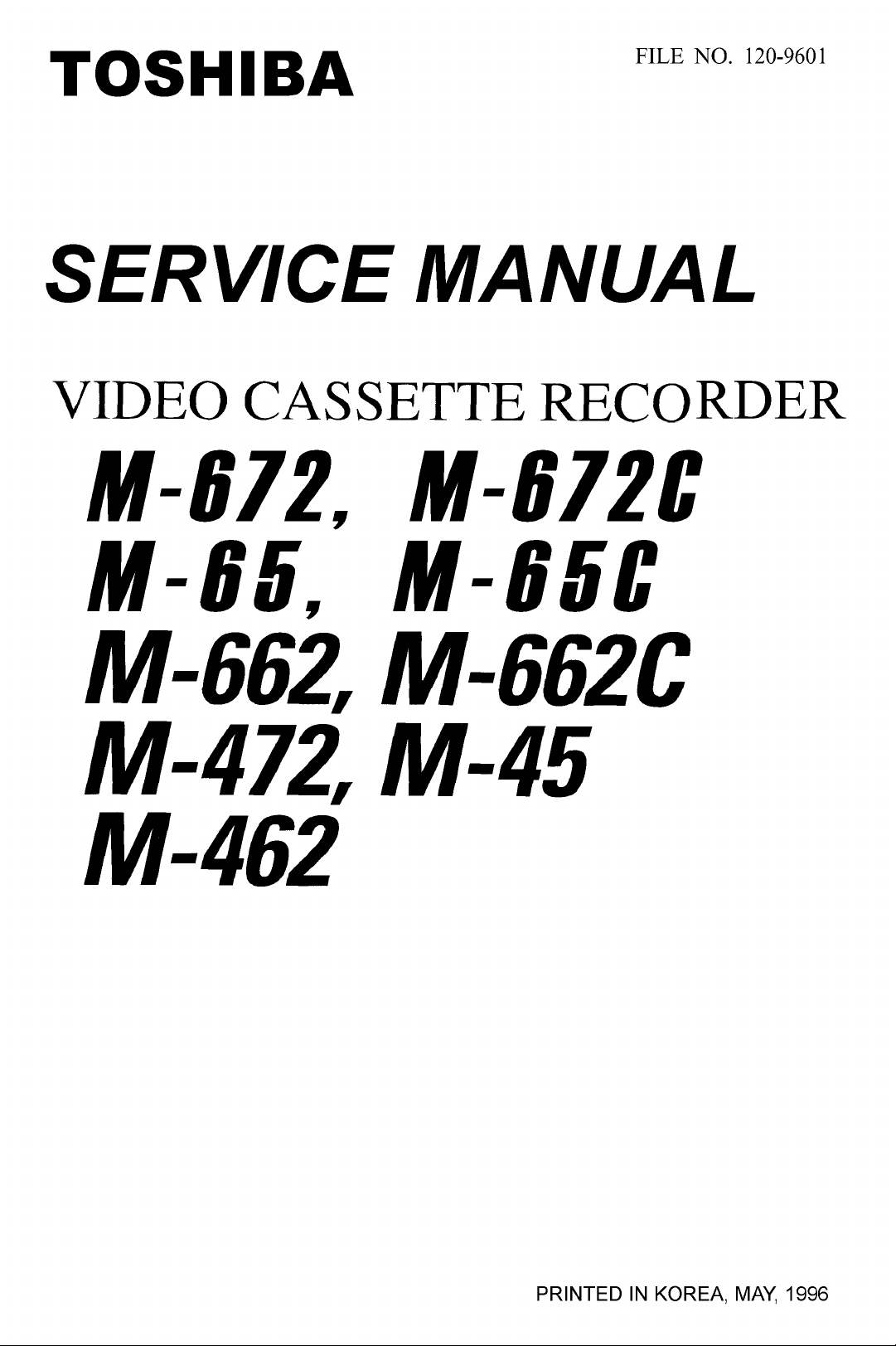
2-l-l. Bottom Cover Removal
1. Remove two
2. Release two
Fig. 1 Bottom Cover Removal
(2)
screws holding the bottom cover.
(2)
tabs from the bottom cover.
0
REMOVE TWO SCREWS
LEASE TWO TABS
2-l-2.Top Cabinet Removal
1. Remove three(3)screws located at the rear of the top
cabinet.
2. Carefully lift the back of the top cabinet and slide it to
the rear to remove.
2-l-3. Front Panel Removal
1. Remove bottom cover and top cabinet (See Fig. 1 to
2. Release three
panel.
3. Release four (4) tabs from the top of the front panel.
4. Tilt the front panel forward to remove.
THREE TABS
(3)
tabs from the bottom of the front
EASE FOUR TABS
2).
Fig. 2 Top Cover Removal
Fig. 3 Front Panel Removal
2-1
Page 3
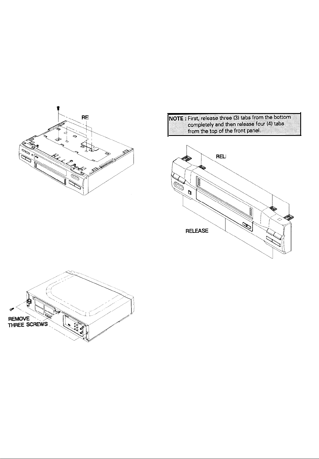
2-2-l. Function PCB Removal
1.
Follow the procedures for removing the bottom cover,
the top cabinet and the panel front. (See Fig.1 to
2. Release five
3. Release
as shown Fig. 4
(5)
tabs on the function board.
connector(CN701)
gently with using the Driver
2-2-3. Main circuit board Removal
1 .Follow the procedures for removing Fig. 1 to 6
3)
2.Release
3.Pull
arrow.
three
(3)
tabs from the frame.
out the main circuit board in the direction of the
Fig. 4 Function PCB Removal
2-2-2. Deck Ass’y Removal
1.
Follow the procedures for removing the bottom cover,
top cabinet and the front panel
2. Remove four
deck ass’y.
3. Remove two
4. Lift the deck ass’y upward to remove.
(4)
screws from the bottom and top of the
(2)
screws from the bottom of the frame.
OREMOVE
FOUR SCREWS
ass'y
(See Fig.1 to
RELEASE THREE
Fig. 6 Main Circuit Board Removal
3)
TABS
Fig. 5 Deck ass’y Removal
2-2
Page 4
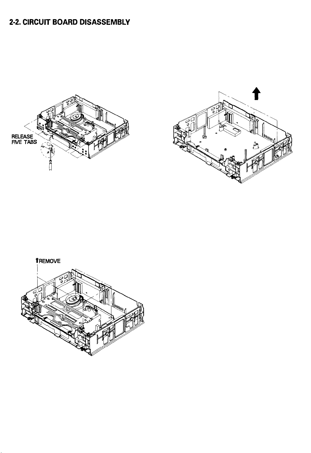
Fig. 7 Instrument Assembly Removal
1. Remove screws
2. Remove screws
3. Release the front panel as shown in Fig. 3
4. Release connector
as shown Fig. 4
5. Remove screws
follow the procedures on next page.
( @, @I 1
( (D, @, @I 1
and release the bottom cover.
and release the top cover.
(CN701)
gently with using the Driver
( @, Q (8 Q), @ )
holding the deck and
2-3
Page 5
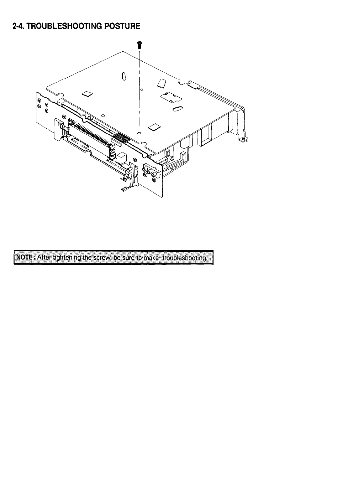
Fig. 8 Trouble Shooting Posture
&
1. Set the main PCB
2. Tighten the screw.
3. Install the Function PCB to Main PCB
DECK ass’y as shown in Fig. 8.
t
TIGHTEN THE SCREW
2-4
Page 6
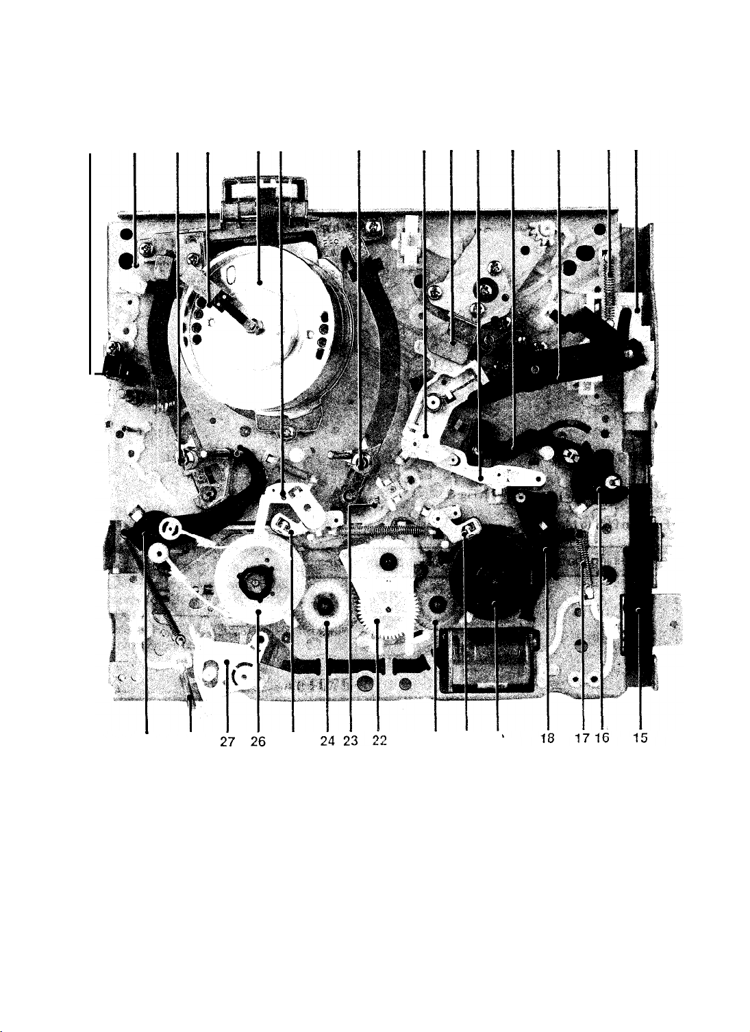
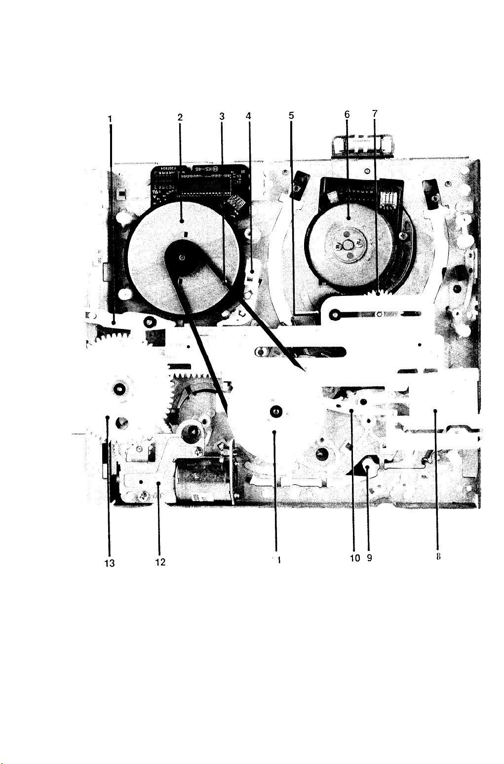
2-5. TAPE TRANSPORT MECHANISM IDENTIFICATION
2-5-l. Deck (lop
1
2 3
View)
5
4
6
7
8 9
10
11
12
13 14
.
29
Fig.9 Deck Parts Locations
FULL ERASE HEAD
1.
STOPPER TAPE
2.
SLIDE GEAR LOADING ASS’Y
3.
HEAD BRUSH ASS’Y 14. SLIDE PINCH
4.
CYLINDER ASS’Y
5.
BRAKE SUB “L” 16. LEVER REVIEW
6.
SLIDE GEAR LOADING ASS’Y “S”
7.
LEVER PINCH COMP 18. BRAKE SUB “R” ASS’Y
8.
FULL ACE HEAD ASS’Y
9.
28
(Top View))
10. LEVER PINCH CAM
25
“T”
11. ARM REVIEW ASS’Y
12. UNIT PINCH ROLLER ASS’Y
13. SPRING SLIDE PUSH
15. SLIDE RACK HOUSING
17. SPRING BRAKE SUB “R”
19. REEL DISK “R” ASS’Y
20. BRAKE MAIN
21 20 19
“R”
2-5
ASS’Y
21. GEAR RELAY
“T”
ASS’Y
22. IDLER ASS’Y
23. PRISM LED
24. GEAR RELAY “S” ASS’Y
25. BRAKE MAIN
26. REEL DISK “L”
“L”
ASS'Y
ASSY
27. LEVER REC SWITCH
28. SPRING REC SWITCH
29. ARM TENSION FULL ASSY
Page 7
2-5-2. Deck (Bottom View)
Fig. 10 Deck Parts
1. LEVER
2. MOTOR
3. BELT CAPSTAN
4. BRAKE CAPSTAN ASS’Y
5. GEAR
6. MOTOR
7. GEAR
SLIDE PINCH
D.D CAPSTAN
LOADING
CYLINDER
LOADING
Locations
I
“R”
"L”
ASS’Y
ASS’Y
(Bottom View)
ii
8.
SLIDE MAIN
9. LEVER REC SWITCH
10. LEVER IDLER CHANGE
11. CLUTCH
12. UNIT LOADING
13. GEAR MASTER
2-B
ASS'Y
a
Page 8
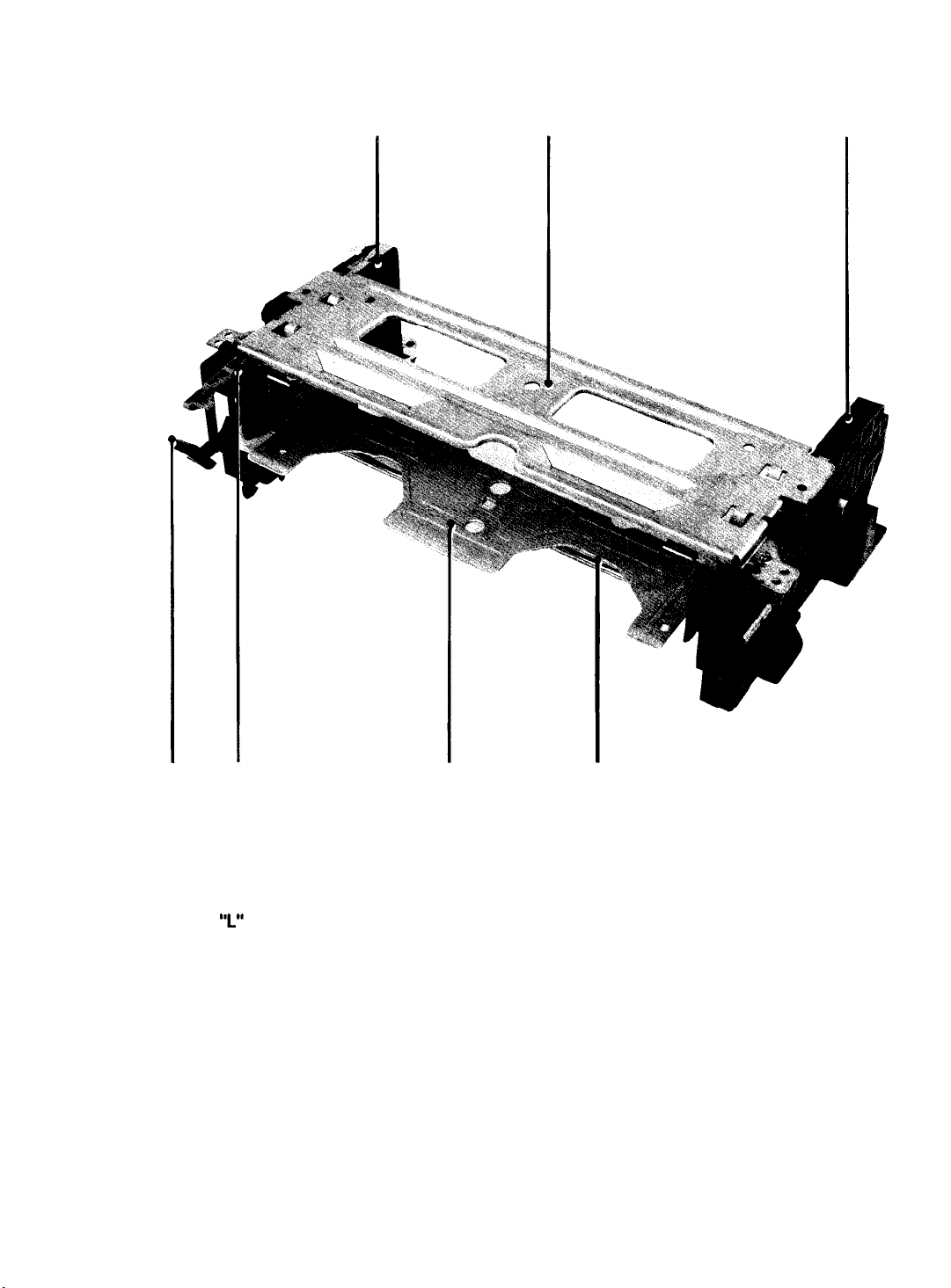
2-6. Housing Assembly
1
2
3
6
Fig. 11 Housing Parts Locations
1. CHASSIS SIDE
7
‘I”
ASS’Y
2. UPPER CHASSIS
3. CHASSIS SIDE
“R”
ASS’Y
4. SHAFT ARM ASS’Y
5. HOLDER CASSETTE ASS’Y
6. LEVER DOOR ASS’Y
7. DOOR
LOCK
5
2-7
4
Page 9
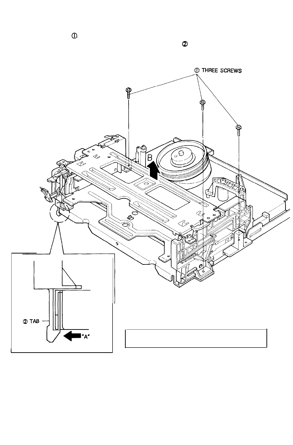
2-6-l. Removal from Main Base
1) Remove three(3) screws
2) Lift the housing ass’y in the direction of arrow ‘B’ while pushing the tab a in the direction of arrow ‘A’.
(Refer to detail drawing)
0.
MAIN BASE
I
<DETAIL>
Fig. 12 Housing Ass’y Removal from Main Base
NOTE : When p ushing the
arrow “A”, take extreme care not to damage
2-8
tab(2)
in the direction of
Page 10
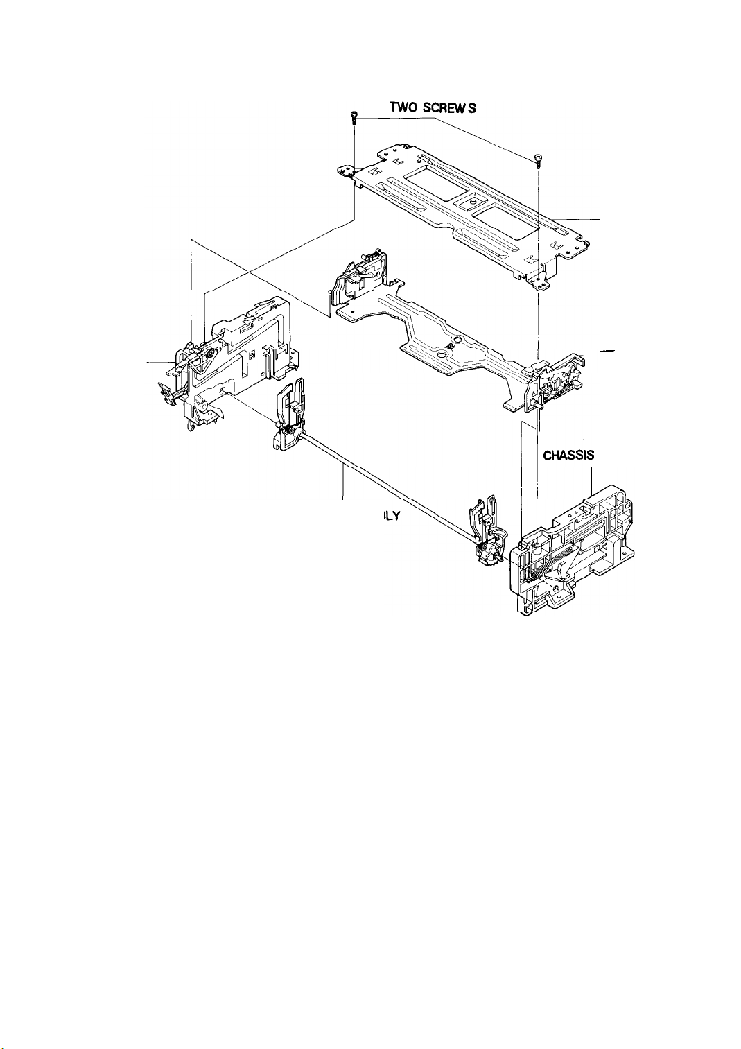
2-6-2. Disassembly
CHASSIS SIDE
‘L’
-
CHASSIS UPPER
-
HOLDER CASSTE
ASSEMBLY
Fig. 13 Housing Ass’y Removal
SHAFT
ARM
ASSEMB
SIDE” R
"
2-9
Page 11
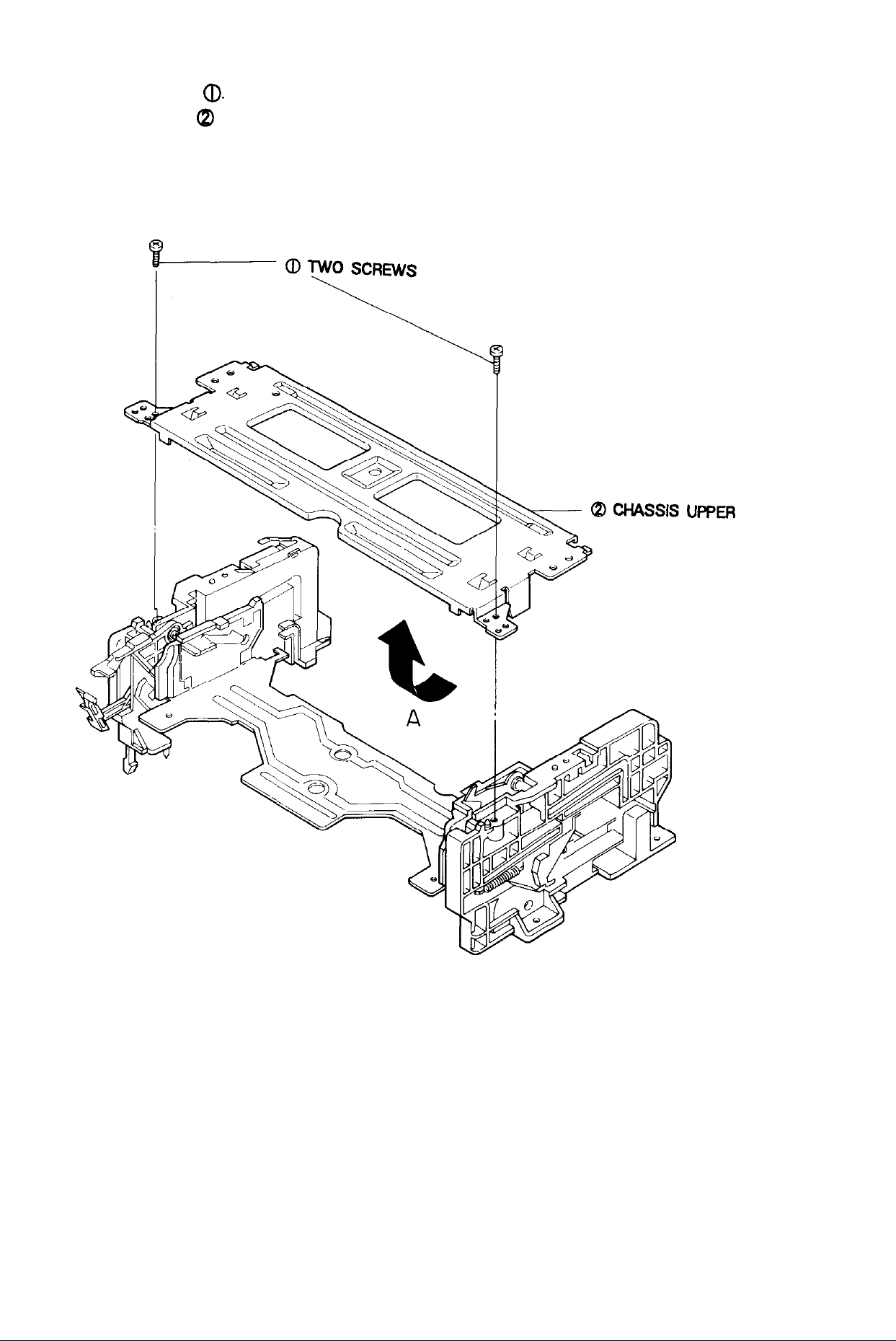
2-6-3. Upper Chassis Removal
1)
Remove
21 Lift the upper chassis QI in the direction of arrow ‘A’
two(2)
screws
a.
Fig. 14 Upper Chassis Removal
2-10
Page 12
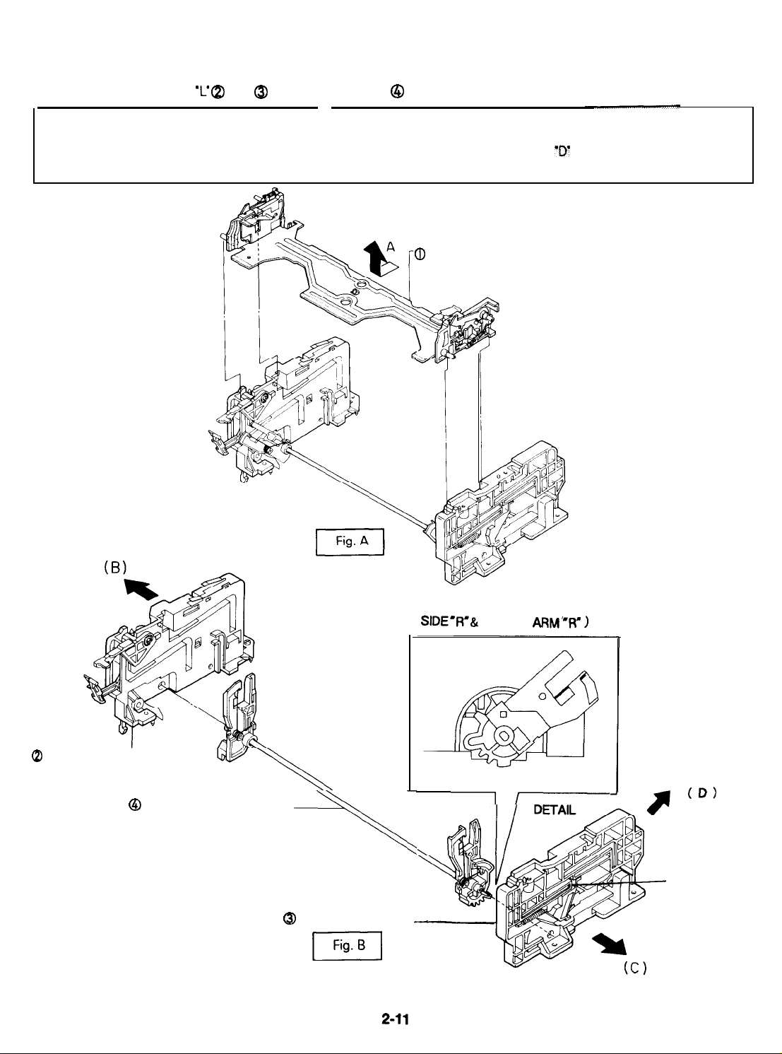
2-6-4. Holder Cassette Ass’y & Chassis Side L/R Removal
1)
Lift the holder cassette (D in the direction of arrow ‘A’ (Refer to Fig. A).
2) Remove the chassis side ‘C @ &
‘R’ @
from shaft arm ass’y @ in the direction of arrows ‘B’, ‘C’ (Refer to Fig. B).
NOTE : If you operate the deck when the
returned to their original position. If this happens by accident, push the slide damper of chassis side ‘R’ in the
direction of arrow
eject mode.
"D",
and return the slide damper in the reverse direction of arrow
holder
cassette
ass’y
is removed, the shaft
a
HOLDER
arm “R’
and the
"D"
CASSETTE ASSEMBLY
slide
when the shaft arm ass’y is in
damper are not
@ CHASSIS
Fig. 15 Holder Cassette Ass’y & Chassis Side
SlDE
l
0 SHAFT
L-
ARM
ASSEMBLY
-+N
a
CHASSIS SIDE "R"
[Fig.1
L/R
Removal
(
REASSEMBLY OF CHASSIS
SIDE-R’& SHAFT
SIDE VIEW
II
ARM’W” 1
(D)
SLIDE DAMPER
Page 13
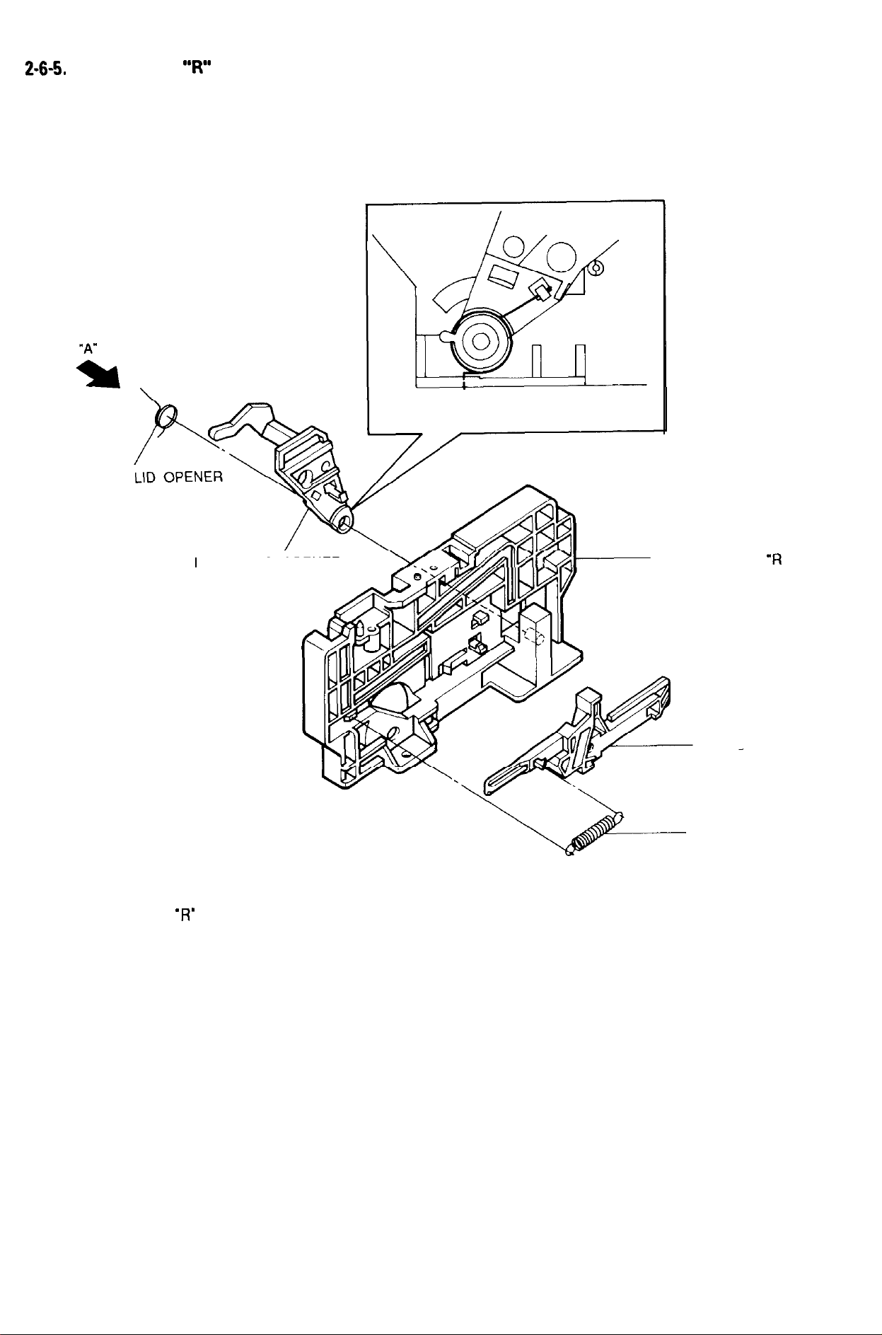
2-6-5.
Chassis Side
SPRING
“R”
Parts Locations
(SIDE VIEW “A”)
Fig. 16 Chassis Side
LEVER-LID OPENER
‘R’
Parts Locations
CHASSIS SIDE
SLIDE - DAMPER
SPRING-SLIDE DAMPER
“R
2-12
Page 14
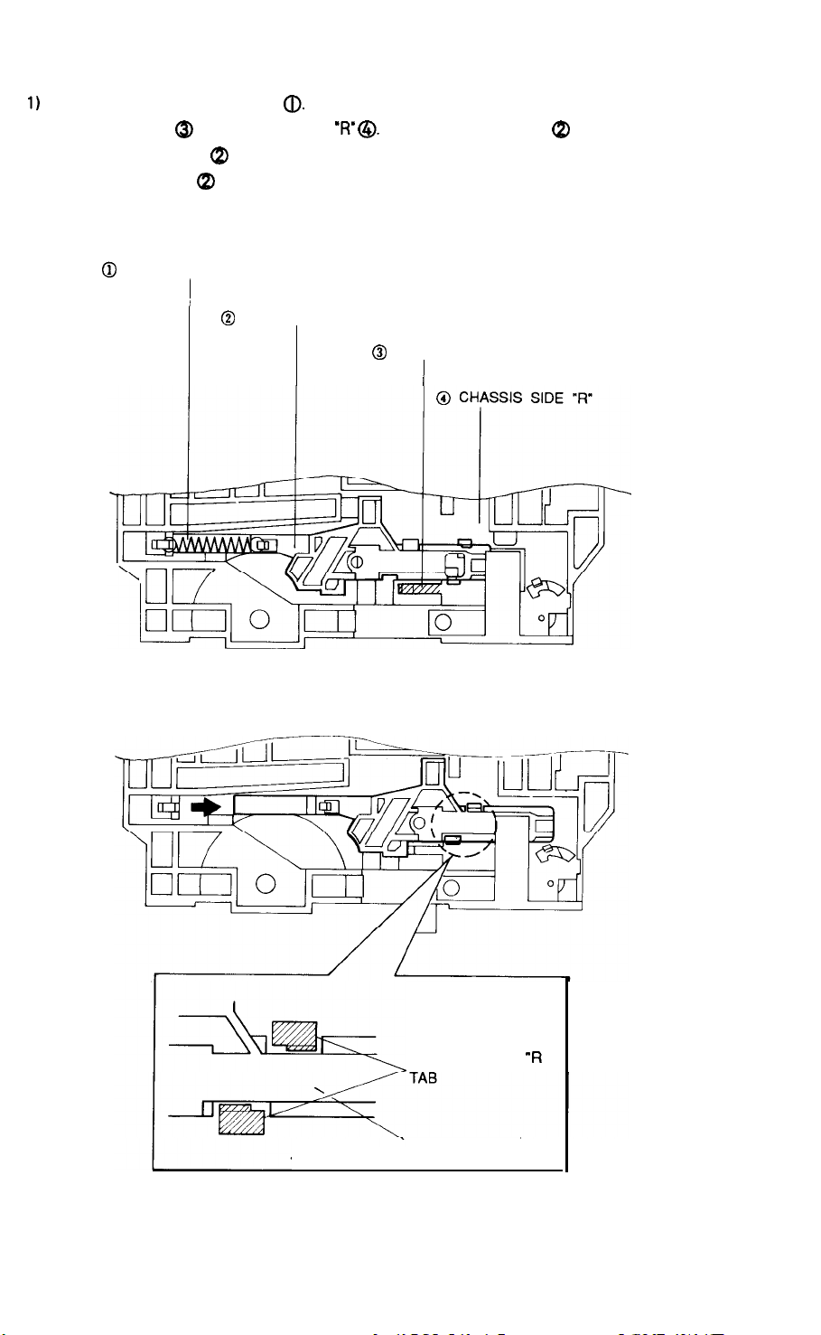
2-6-6. Slide Damper Removal
1)
Remove the spring slide damper
2) Push the stopper @ of the chassis side ‘R’ @. Move the slide damper @ in the direction of arrow.
3) Align the slide damper QI with the chassis side tab (as shown detail drawing).
4) Lift the slide damper @ to remove.
@
SPRING SLIDE DAMPER
@.
)
@
SLIDE DAMPER
@
STOPPER
I
Fig. 17 Slide Damper Removal
<DETAIL>
CHASSIS SIDE
SLIDE DAMPER
2-13
“R
Page 15
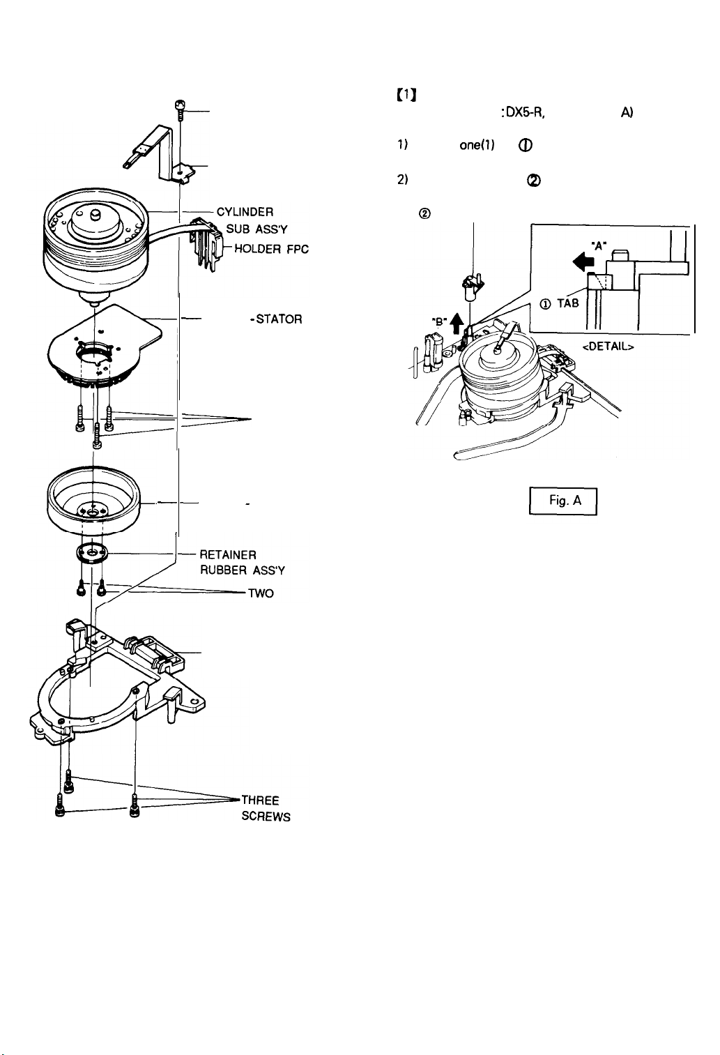
2-7. Cylinder Ass’y
2-7-l. Exploded View of Cylinder Ass’y
ONE SCREW
F-
HEAD BRUSH
-
MOTOR -
STATOR
2-7-2. Stopper Tape
(1)
Stopper Tape Removal
(Only for deck :
1)
Release
one(l)
(Refer to detail drawing)
2)
Lift the stopper tape 0, in the direction of arrow ‘B’.
@ STOPPER TAPE
DXS-R,
Refer to Fig.
A)
tab @ in the direction of arrow ‘A’.
p
- -
MOTOR - ROTOR
THREE
SCREWS
Fig. 19 Stopper Tape Removal
SCREWS
CYLINDER BASE
Fig. 18 Exploded View of Cylinder Ass’y
2-14
Page 16
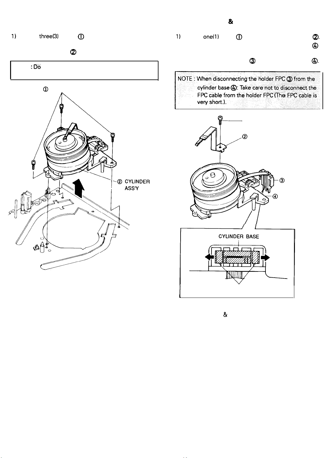
2-7-3. Cylinder Ass’y Removal from Main Base
1)
Remove threef3) screws @ holding the main base and
the cylinder ass’y.
2) Lift the cylinder ass’y Q in the direction of arrow.
NOTE
: Do
not touch the video heads during removal or.
installation.
@
THREE
SCREWS
2-7-4. Head Brush & Holder FPC Removal
1)
Remove
one(l)
screw @ and then lift the head brush
2) Release the holder FPC tab holding the cylinder base @
in the direction of arrow. (Refer to detail drawing)
3) Disconnect the holder FPC @ from the cylinder base
NOTE : When disconnecting the holder FPC @from the
cylinder base 0: Take care not to disconnect the
FPC cable from the holder FPC
(The
FPC cable is
j
a.
0.
Fig. 20 Cylinder Ass’y Removal from Main Base
IF---
HOLDER FPC TAB
I
<DETAIL : BOTTOM VIEW>
@ ONE SCREW
0
HEAD BRUSH
@
@
HOLDER FPC
CYLINDER BASE
J
Fig. 21 Head Brush & Holder FPC Removal
2-15
Page 17
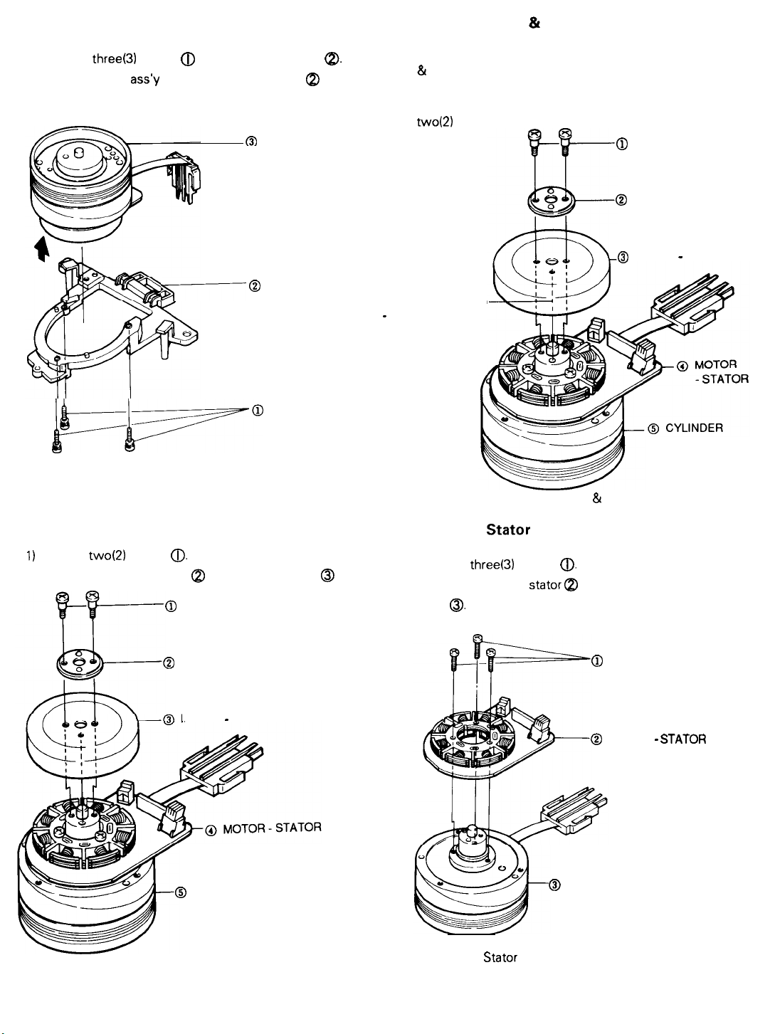
2-7-5. Cylinder Ass’y Removal from Cylinder Base
2-7-7. Motor Rotor & Cylinder Sub Ass’y
1) Remove
2) Lift the cylinder
direction of arrow.
three(3)
ppa
screws 0 from the cylinder base
ass)
@from the cylinder base (p in the
m
CYLINDER ASS’Y
@
CYLINDER BASE
7
THREE SCREWS
@.
1) Make sure that phase matching holes of the motor rotor
81
the cylinder sub ass’y are aligned correctly as shown in
Fig. 16 (Refer to phase matching hole)
2) Reinstall the retainer lever ass’y @and secure with
two(2) screws.
@
TWO SCREWS
@
RETAINER
RUBBER ASS’Y
@
MOTOR - ROTOR
PHASE MATCHING
-
HOLE
SUB ASS’Y
Fig. 22 Cylinder Ass’y Removal from Cylinder Base
2-7-6. Motor Rotor Removal
1)
Remove two(2) screws
2) Lift the retainer lever ass’y @ and the motor rotor @
0.
@
TWO SCREWS
@
RETAINER
RUBBER ASS’Y
MOTOR - ROTOR
@
CYLINDER SUB ASS’Y
Fig. 24 Assembly of Motor Rotor & Cylinder Sub Ass’y
2-7-8. Motor Stator Removal
1) Remove
2) Remove the motor stator a from the cylinder sub
ass’y
Q.
three(3)
screws
@
@).
@
THREE SCREWS
@
MOTOR -
CYLINDER SUB ASSY
STATOR
Fig. 23 Motor Rotor Removal
2-l 6
Fig. 25 Motor
Stator
Removal
Page 18
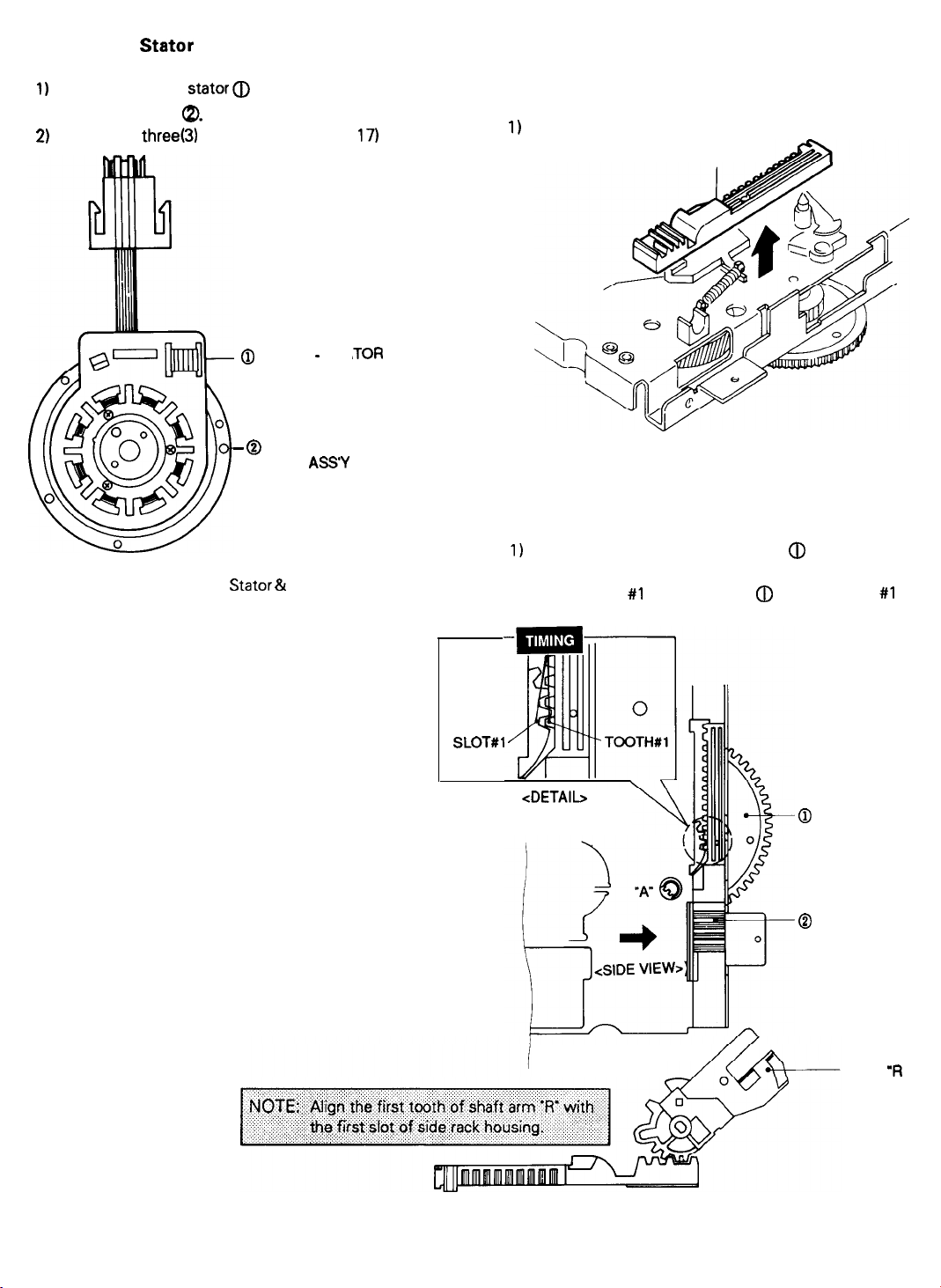
2-7-9. Motor
Stator
& Cylinder Sub Ass’y
2-8. Main Deck Removal & Reassembly
1)
Reinstall the motor stator (D toward the FPC cable of
cylinder sub ass’y
2)
Secure with three(3) screws. (Refer to Fig.
Fig. 26 Assembly of Motor Stator & Cylinder Sub Ass’y
Q.
. @ MOTOR - STA
- @
CYLINDER
SUB
ASS’Y
17)
,TOR
2-8-l. Slide Rack Housing Removal
1)
Lift the slide rack housing in the direction of arrow.
SLIDE RACK HOUSING
Fig. 27 Slide Rack Housing Removal
2-8-2. Assembly of Slide Rack Housing & Gear
Master
1)
Confirm that the hole of gear master @ and the hole ‘A
of main base are aligned correctly. (Eject mode)
2) Align the slot #l of gear master a with the tooth #l of
slide rack housing. (Refer to timing point)
SLOTS1
<DETAIL>
<TOP VIEW>
<SIDE VIEW>
Fig. 28 Assembly of Slide Rack Housing & Gear Master
@
GEAR MASTER
@
SLIDER RACK
HOUSING
ARM
‘R
2-17
Page 19
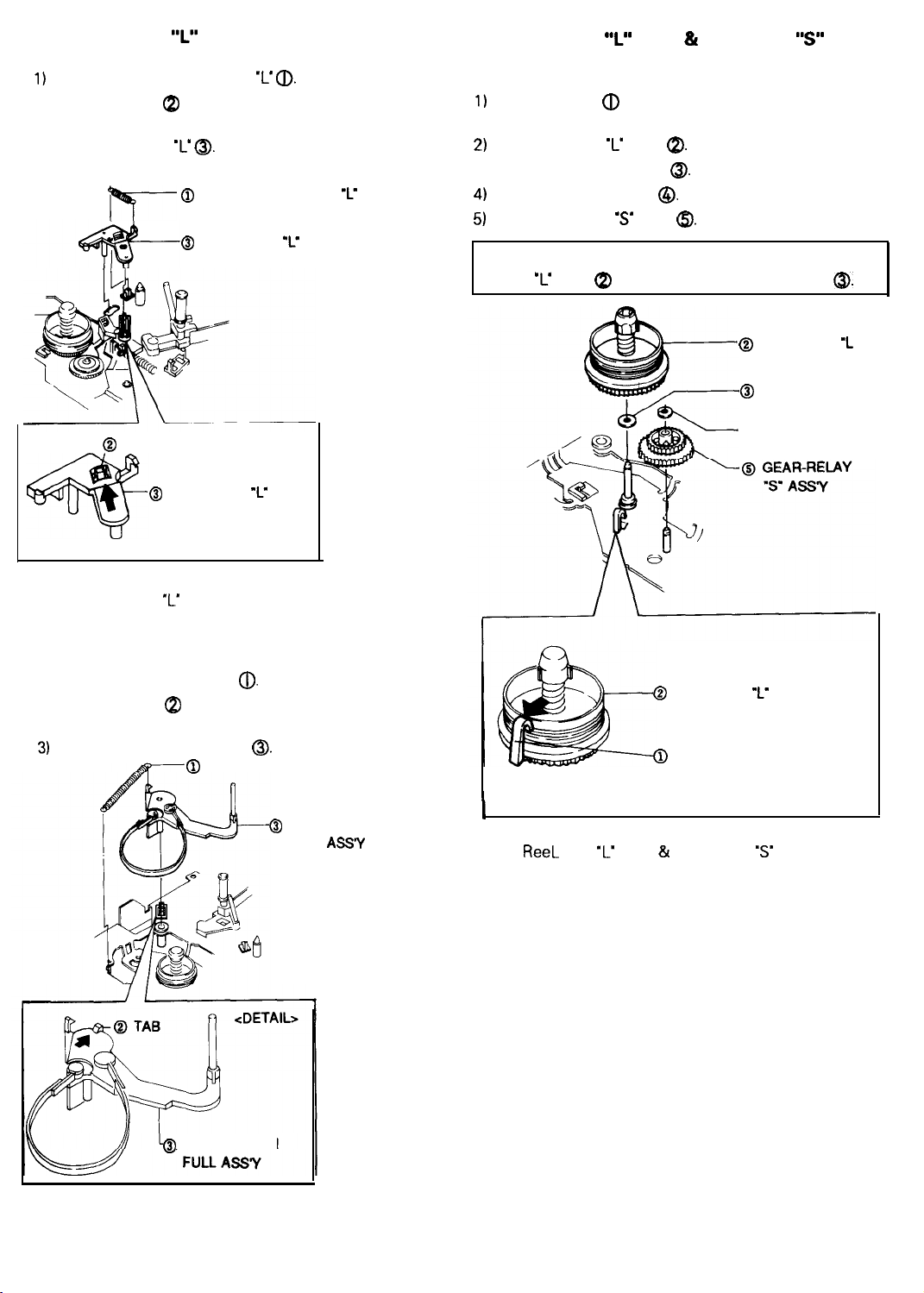
2-8-3. Brake Sub
1)
Remove the spring brake sub ‘L’
2) Release the tab Q) in the direction of arrow.
(Refer to detail drawing)
3) Lift the brake sub ‘L
“L”
Removal
a.
0.
@
SPRING-BRAKE SUB ‘L.
r7-
@
BRAKE-SUB ‘L”
2-8-5. Reel Disk
‘I”
Ass’y & Gear Relay
“s”
Ass’y Removal
1)
Release the tab
(Refer to detail drawing)
2)
Lift the reel disk ‘L ass’y
3) Remove the washer plain
4)
Remove the washer slit
5)
Lift the gear relay ‘S’ ass’y
NOTE : When reinstalling, be sure to install the reel disk
‘L’ ass’y QI after installing the washer plain
(J)
in the direction of arrow.
a.
a.
@.
a.
@
@I
REEL-DISK
ASSY
WASHER-PLAIN
@.
‘L
@
TAB
@
<DETAIL>
Fig. 29 Brake Sub
BRAKE-SUB
‘L’
Removal
“L”
2-8-4. Arm Tension Full Ass’y Removal
1) Remove the spring tension
2) Release the tab Q in the direction of arrow.
(Refer to detail drawing)
3)
Lift the arm tension full ass’y
0.
@
0.
SPRING-TENSION
@
ARM-TENSION
FULL
ASS’Y
I
Fig. 31
@
REEL-DISK
Q)
TAB
<DETAIL>
ReeL
Disk ‘L’ Ass’y & Gear Relay
Removal
@WASHER-SLIT
“L’
ASSY
‘S’
Ass’y
@
ARM-TENSION
Fig. 30 Arm Tension Full Ass’y Removal
2-18
Page 20
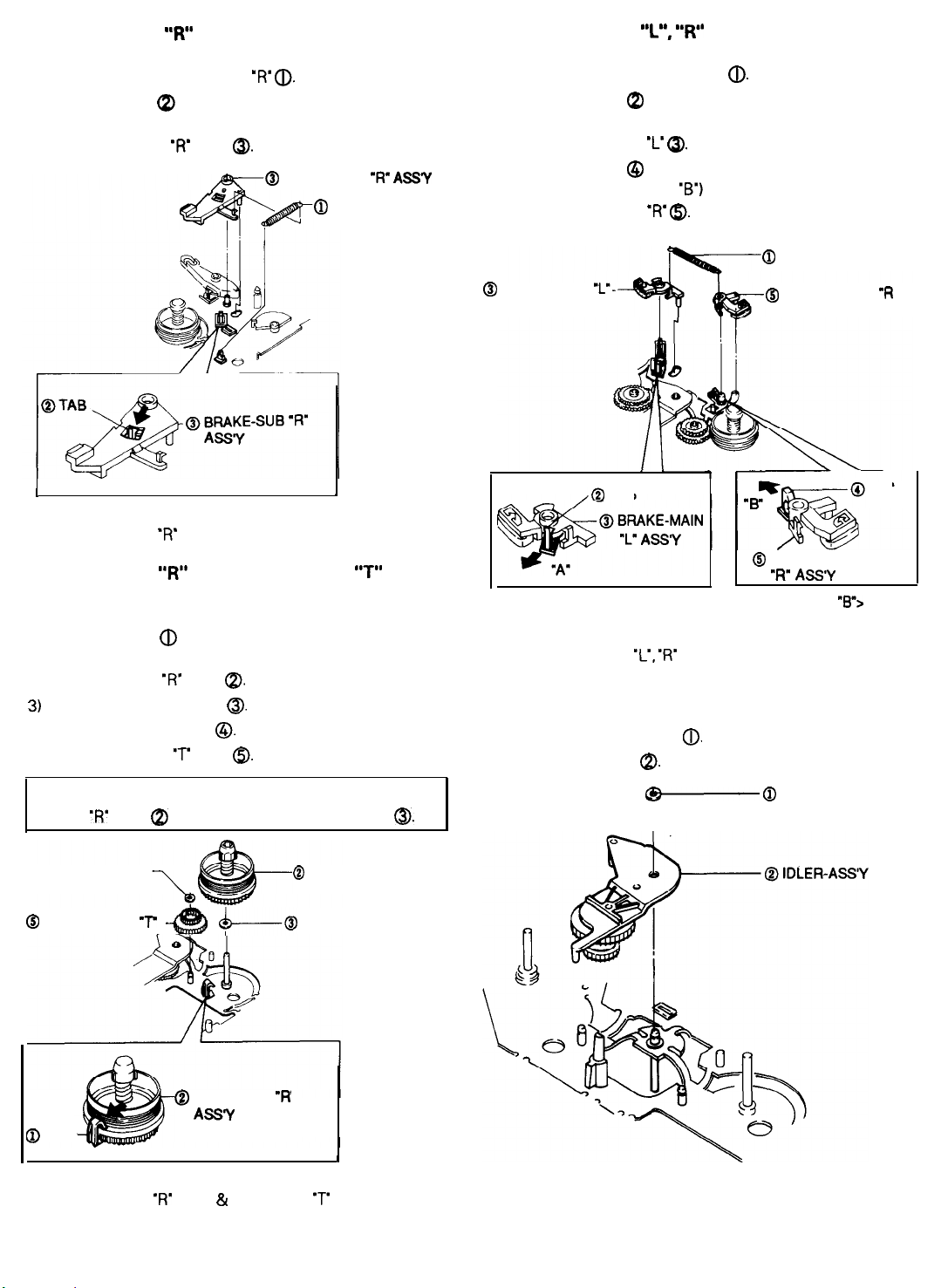
2-8-6. Brake Sub
“R”
Ass’y Removal
2-8-8. Brake Main
“L”, “R”
Ass’y Removal
1) Remove the spring brake sub ‘R’
2) Release the tab Cp in the direction of arrow.
(Refer to detail drawing)
3) Lift the brake sub ‘R’ ass’y
I
<DETAIL>
Fig. 32 Brake Sub ‘R’ Ass’y Removal
2-8-7. Reel Disk
“R”
Ass’y & Gear Relay
@.
@
a.
BRAKE-SUB
@
SPRING-BRAKE
Removal
‘R” ASSY
SUB l R
I
“T”
1) Remove the spring brake main
2) Release the tab a in the direction of arrow ‘A’.
(Refer to detail drawing ‘A’)
3) Lift the brake main ‘L’
4) Release the tab @ in the direction of arrow ‘B’.
(Refer to detail drawing ‘B’)
5) Lift the brake main ‘R’
@
BRAKE-MAIN
ASSY
<DETAIL “A”>
,O
I’-
TAB
a.
a.
@.
0
SPRING-BRAKE MAIN
@
BRAKE-MAIN
ASSY
“B
@
BRAKE-MAIN
“R” ASSY
<DETAIL
“R
TAB
“B”>
1) Release the tab a in the direction of arrow.
(Refer to detail drawing)
2) Lift the reel disk ‘R’ ass’y
3)
Remove the washer plain
4) Remove the washer slit
5) Lift the gear relay
NOTE : When reinstalling, be sure to install the reel disk
‘R’
ass’y 8) after installing the washer plain
@WASHER-SLIT
@
GEAR-RELAY
@
TAB
Fig. 33 Reel Disk ‘R’ Ass’y & Gear Relay ‘T’ Removal
7”
<DETAIL>
a.
0.
0.
‘T’
ass’y
@I.
&-----@
@
REEL-DISK
ASSY
@
REEL-DISK l R
ASSY
WASHER-PLAIN
“R
1
0.
Fig. 34 Brake Main ‘L’,
‘R’
Ass’y Removal
2-8-9. Idler Ass’y Removal
1) Remove the washer slit
2) Lift the idler ass’y
Fig. 35 Idler Ass’y Removal
0.
a.
@-
@ WASHER-SLIT
2-19
Page 21
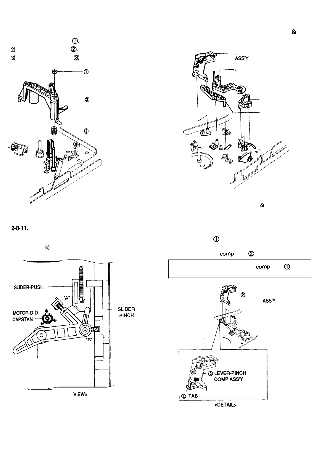
2-8-10. Unit Pinch Roller Ass’y Removal
1) Remove the washer slit
2)
Lift the unit pinch roller
3)
Lift the spring arm pinch
(D.
@.
a.
2-8-12. Exploded View of Lever Pinch Comp Ass’y,
Lever Pinch Cam, Arm Review Ass’y &
Lever Review Ass’y
LEVER-PINCH COMP
&p
Fig. 36 Unit Pinch Roller Ass’y Removal
2-8-11.
Assembly of Unit Pinch Roller
1) Install the unit pinch roller as shown in Fig. 29.
(Refer to A,
6)
Q WASHER-SLIT
@
UNIT-PINCH ROLLER
@
SPRING-ARM PINCH
ARM-REVIEW ASSY
LEVER-REVIEW
LEVER-PINCH CAM
Fig. 38 Exploded View of Lever Pinch Comp Ass’y, Lever
Pinch Cam, Arm Review Ass’y 81 Lever Review
Ass’y
2-8-13. Lever Pinch Comp Ass’y Removal
1) Release the tab @ in the direction of arrow.
(Refer to detail drawing)
2) Lift the lever pinch camp ass’y
@.
UNIT-PINCH ROLLER
.
Fig. 37 Assembly of Unit Pinch Roller
-
<TOP
VIEW>
!-II
t-l
I y
NOTE : Don’t touch the lever pinch camp ass’y @ to
audio head base during removal.
@
LEVER-PINCH
COMP
<DETAIL>
Fig. 39 Lever Pinch Comp Ass’y Removal
2-20
ASS’Y
Page 22
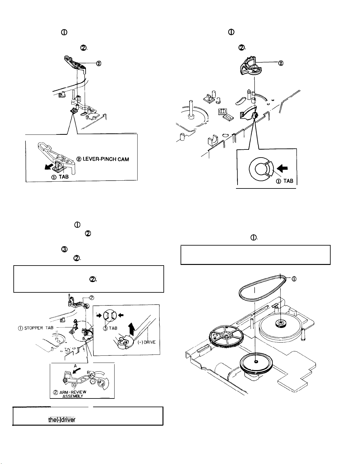
2-8-14.
Lever Pinch Cam Removal
1) Release the tab a in the direction of arrow.
(Refer to detail drawing)
2)
Lift the lever pinch cam
a.
2-8-18. Lever Review Removal
(j)
1) Release the tab
(Refer to detail drawing)
2) Lift the lever review
in the direction of arrow.
a.
@
LEVER-PINCH CAM
r
<DETAIL>
Fig. 40 Lever Pinch Cam Removal
2-8-l 5. Arm
1) Push the stopper tab (D in the direction of arrow.
2) Pull the arm review ass’y Q in the direction of arrow ‘A’
and then confirm ‘B’. (Refer to detail drawing ‘A’)
3) Release the tab
the arm review ass’y
Review Ass’y Removal
@ in the direction of arrow and then lift
a.
@ LEVER REVIEW
<DETAIL>
Fig. 42 Lever Review Removal
2-8-17.
1) Remove the belt capstan
Belt Capstan Removal
a.
NOTE : Take extreme care not to touch the grease when
removing or reinstalling.
NOTE : Take extreme care not to damage when removing
the arm review ass’y
(B
part of detail drawing
I
NOTE:
Fig. 41 Arm Review Ass’y Removal
Be sure to remove the arm review assy with
using
the(-)dri
Cp.
A)
ARM REVIEW ASSEMBLY
\ \,
DETAIL “A”
DETAIL "B”
Fig. 43 Belt Capstan Removal
2-21
@
BELT-CAPSTAN
Page 23
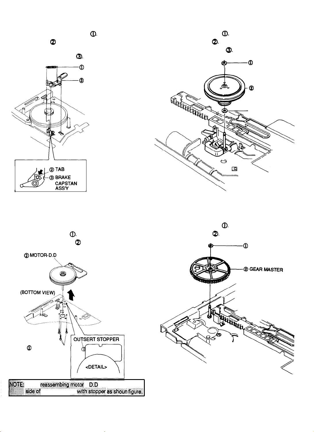
2-8-18.
1)
2)
3)
Brake Capstan Ass’y Removal
Remove the spring brake capstan
Release the tab Q in the direction of arrow.
(Refer to detail drawing)
Lift the brake capstan ass’y
(J).
a.
@
SPRING-BRAKE
CAPSTAN
@
BRAKE CAPSTAN
ASSY
l--------l
2-8-20.
Clutch Ass’y Removal
1)
Remove the washer slit
2)
Lift the clutch
3) Remove the washer plain
ass’y
QI.
a>.
9-0
@.
WASHER-SLIT
Q
CLUTCH-ASSY
@WASHER-PLAIN
1
<DETAIL>
Fig. 44 Brake Capstan Ass’y Removal
2-8-19.
Motor D.D
1)
Remove
2)
Lift the motor D.D capstan (p in the direction of arrow.
(Bottom view)
three(3)
Q MOTOR-D.P
(TOP VIEW)
0
THREE SCREWS
Capstan
screws @. (Top view)
CAPSTAN
1
Removal
Fig.46 Clutch Ass’y Removal
2-8-21. Gear Master Removal
1)
Remove the washer slit
2)
Lift the gear master
Q).
@
0
WASHER-SLIT
C When
Fig. 45 Motor D.D Capstan Removal
reyemf$qkytor -
.sid$.of
capstan wafer
R-R
&th-doppef
capstan@,. align
trs’doun
fi&ia,.
Fig. 47 Gear Master Removal
2-22
Page 24
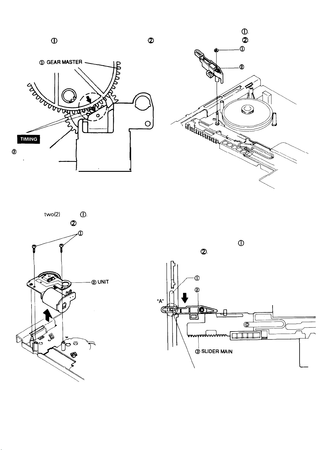
2-8-22.
Assembly of Gear Master
2-8-24.
Lever Slide Pinch Removal
1)
When reinstalling, be sure to align the arrow mark of
gear master
(Refer to timing point)
@
GEAR WORM WHEEL
UNIT LOADING
a
with gear home of gear worm wheel
00
Fig. 48 Assembly of Gear Master
2-8-23.
Unit Loading Removal
1) Remove the washer slit
a
2) Lift the lever slide pinch
a.
a,
@
WASHER-SLIT
@I
LEVER SLIDER PINCH
/
<-,
Fig. 50 Lever Slide Pinch Removal
1)
Remove twoQ) screws
2) Lift the unit loading @ in the direction of arrow.
0.
Q
TWO SCREWS
p--?
LOADING
Fig. 49 Unit Loading Removal
2-8-25.
SLIDER PINCH BOSS
Assembly of Lever Slide Pinch
1)
Pull the slide pinch @to the end in the direction
of arrow.
2) Insert the slide pinch
pinch (p. (Refer to ‘A’ part)
@
SLIDER-PINCH
LEVER SLIDER PINCH
Fig. 51 Assembly of Lever Slide Pinch
(j)
into the hole of lever slide
2-23
Page 25
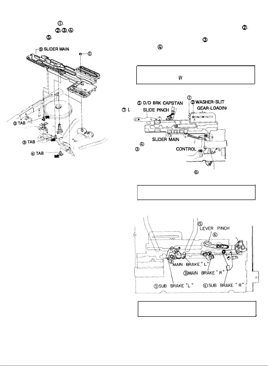
2-8-28. Slide Main Removal
2-8-27. Assembly of Slide Main
1) Remove the washer slit
2) Release
3) Lift the slide main
three(3)
tabs
6).
a.
QI, @,
@ in the direction of arrow.
@
WASHER SLIT
CBL
1) Install the shaft of gear loading ‘R’ ass’y into the left of
the main slide hole and secure with the washer slit
(Refer to ‘A’)
2) Insert the lever tension control
change @ into the slide main hole. (Refer to
3) After confirming the above items
main and secure with tabs
NOTE:
Be sure to assemble the side main when the
gear loading
i/r
assy is inunloading posision.
@
Q)
and the lever idler
1), 2)
install the slide
(a,
b,
c).
GEAR-LOADING’R’ASSEMBLY
a
EVER
0
LEVER-IDLER CHANGE
0
LEVER-TENSION
’
CONTB~~
G "L" ASSEMBLY
I
a.
‘B’)
Fig. 52 Slide Main Removal
7
@
LEVER-REC
NOTE :
Fig. 53 Assembly of Slide Main (Bottom view)
‘r-------’
NOTE: Six parts should be installed into the side
Seven parts should be installed into the
side main hole.
LEVER REVIEW
\
main hold.
S/W
I
CAM
I
A
Fig. 54 Assembly of side
2-24
Main(Top
view)
Page 26
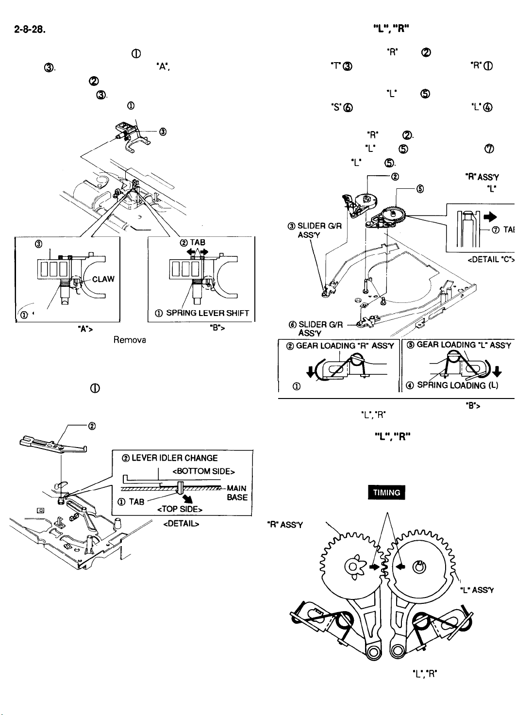
2-8-28.
Lever Shift Ass’y Removal
2-8-30. Gear Loading
‘I”, “R”
Ass’y Removal
1) Hang the spring lever shift (D to the claw of the lever
shift @. (Refer to detail drawings ‘A’, ‘B’)
2) Release the tab @ in the direction of arrow.
3) Lift the lever shift
@I
LEVER SHIFT
I
F
*
Fig. 55 Lever Shift Ass’y
,
@
SPRING LEVER SHIFT
<DETAIL
“A”>
@.
@
SPRING LEVER SHIFT
\
@
LEVER SHIFT
<DETAIL ‘B’>
Remova
1) Remove the gear loading ‘R’ ass’y @ from the slide
guide roller ‘T
in the direction of arrow. (Refer to detail drawing ‘A’)
2) Remove the gear loading ‘L’ ass’y Q from the slide
guide roller
in the direction of arrow. (Refer to detail drawing ‘B’)
3) Lift the gear loading ‘R’ ass’y
4) Lift the gear loading ‘L’ ass’y @ by pushing the tab Q of
the gear loading ‘L’ ass’y a. (Refer to detail drawing ‘C’)
ASS’Y
(3,
by pushing the spring loading ‘R’
‘s’
@ by pushing the spring loading ‘L’ @
a.
f---- @
GEAR LOADING
@
GEAR LOADING
44’
a
‘R’ AS’Y
‘L’
ASS
2-8-29. Lever Idler Change Removal
1) Release the tab @ in the direction of arrow.
(Refer to detail drawing)
2) Lift the lever idler change
7
@ LEVER IDLER CHANGE
Fig. 56 Lever Idler Change Remo
@
SPRING LOADING (R)
<DETAIL “A”>
Fig. 57 Gear Loading ‘L’,
2-8-31. Gear Loading
1) When reinstalling, be sure to align two arrows as shown
in Fig. 58. (Refer to timing point)
GEAR LOADING
“R’ASS’Y
ALIGN TWO ARROWS
\
11 @ SPRlNG LoADlNG (L)
‘R’
Ass’y Removal
‘I”, “R”
<DETAIL
Ass’y
9%
GEAR LOADING
Fig. 58 Assembly of Gear Loading ‘L’, ‘R’ Ass’y
2-25
Page 27
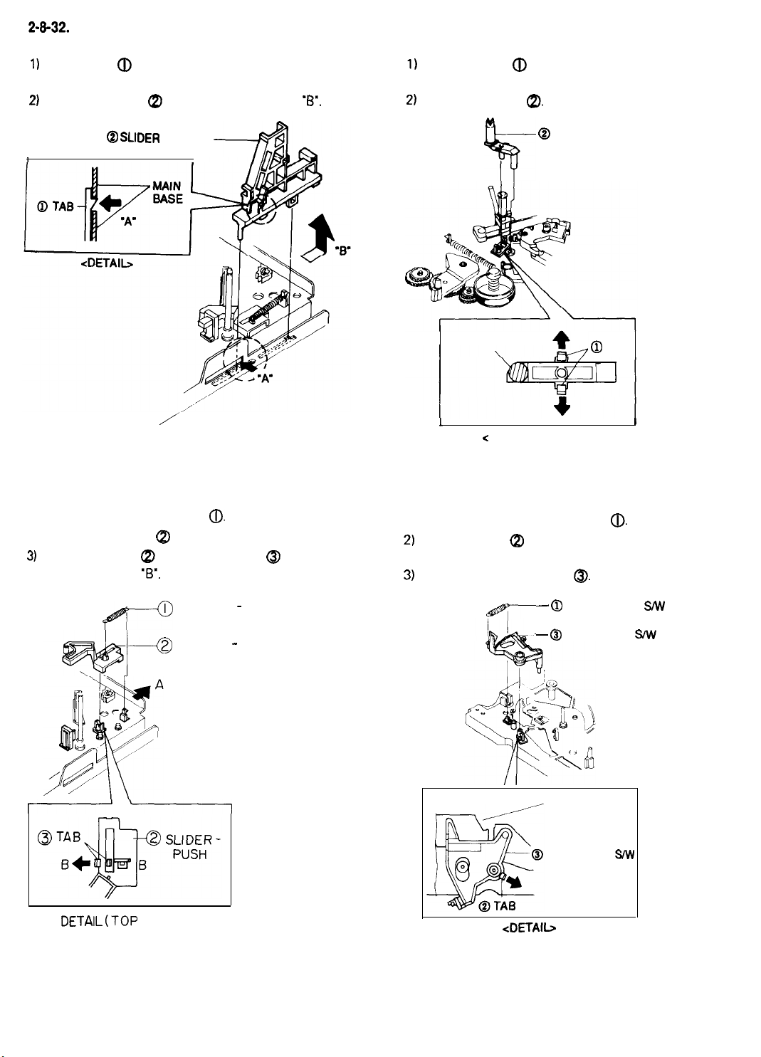
2-8-32.
Slide Pinch Removal
1)
Push the tab @ in the direction of arrow ‘A’.
(Refer to detail drawing)
2)
Lift the slide pinch @ in the direction of arrow
@ SLIDER
I
PINCH
‘6’.
2-8-34. Prism LED Removal
1)
Release the tab @ in the direction of arrow.
(Refer to detail drawing)
2)
Lift the prism LED
Q).
0
PRISM-
LED
VT
PRISM
LED
@
TAB
/
Fig. 59 Slide Pinch Removal
2-8-33. Slide Push Removal
1) Remove the spring slide push
2) Push the slide push Q in the direction of arrow ‘A’.
3)
Lift the slide push Q) by pushing the tab Q in the
direction of arrow ‘B’. (Refer to detail drawing)
fl
4
0.
SPRING - SLIDE PUSH
SLIDER - PUSH
l------I
1
<
DETAIL
Fig. 61 Prism LED Removal
+
-TOP VIEW>
I
2-8-35. Lever Record Switch Removal
1) Remove the spring record switch
2)
Release the tab QI in the direction of arrow.
(Refer to detail drawing)
3)
Lift the lever record switch
__ @
6
SPRING REC
- @
LEVER REC
MAIN BASE
0.
0.
S/W
C/W
DETAIL(TOP VIEW)
Fig. 60 Slide Push Removal
<DETAIL
Fig. 62 Lever Record Switch Removal
2-26
LEVER REC
SIW
Page 28
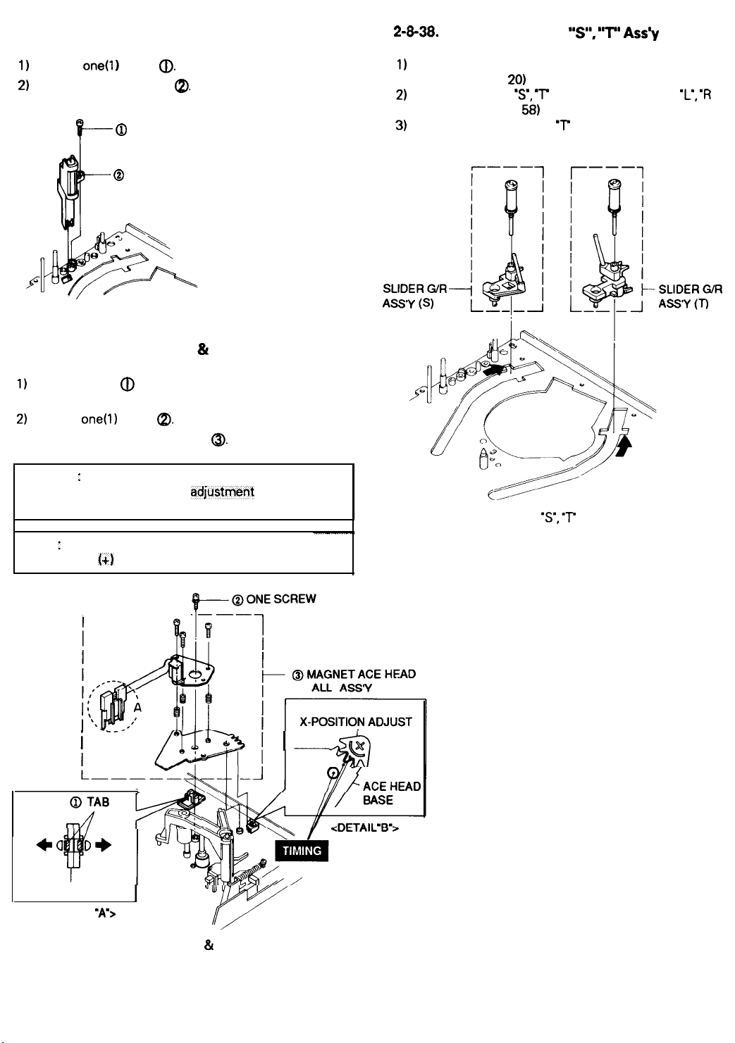
2-8-36. Full Erase Head Removal
1)
Remove one0 ) screw
2)
Lift the magnet WE head 8).
@
f---
@
Fig. 63 Full Erase Head Removal
2-8-37. ACE Head Removal & Reassembly
1)
Release the tab @ holding holder ACE toward arrows.
(Refer to detail drawing ‘A’)
2)
Remove
3) Lift the magnet ACE head ass’y
one(l)
screw
Q).
ONE SCREW
MAGNET F/E HEAD
QI.
@.
2-8-38.
Slide Guide Roller “s”,
1)
Remove the cylinder ass’y from the main base.
(Refer to Fig. 19,
2)
Remove the slide
ass’y. (Refer to Fig.
3)
Move the guide roller ‘S’, ‘T ass’y to slot and then lift it
to remove. (Refer to arrow)
20)
‘s’, T
from the gear loading ‘L’,
58)
“T” Ass’y
Removal
‘R
Assembly : When reinstalling, be sure to align the three
teeth of X-Position adju$tment gear with the
two slot of ACE head base.
NOTE : When adjusting the X-position adjustment gear
using
1~)
driver, do not adjust by force.
r-------
i --
I
---%J
r-n/
-r-z
,#
Fig. 65 Slide Guide Roller
‘s’, ‘T
Ass’y Removal
HOLDER ACE
<DETAIL
Fig. 64 ACE Head Ass’y Removal & Reassembly
I
‘A=>
“ul
1
7
2-27
Page 29

2-8-39. Slide Guide Roller “S”,
“T”
Ass’y
(When all parts except the cylinder
assembly are removed.)
1) Push four(4) Lever Locks a of the housing ass’y
Simultaneously. (Refer to Fig. 66)
2) Push the holder cassette
turning the gear master Q toward arrow ‘A’.
(Refer to Fig.
3) Load the gear loading L, R ass’y @. a to the middle
position of guide rail by turning the gear master
toward arrow ‘A’. (Refer to Fig. 66, 67)
4)
Install the slide guide roller S, T @, QJ into rail slot and
then move it to the position of gear loading L, R ass’y
0, a.
5)
Turn the gear master @ toward arrow ‘A’. (Eject mode)
66)
(Refer to Fig.
67)
ass)
@toward arrow ‘B’ while
Q
k2_0
Fig. 66 How to operate the Housing Ass’y
HOMIER CASSETTE
ASSEMBLY
@
SLIDER
ASSY (T)
G/R
Fig. 67 Assembly of Slide Guide Roller
‘s’, ‘r
Ass’y
2-28
Page 30

3-2. TAPE TRANSPORT SYSTEM
3-2-l. Location of Tape Transport Adjustment (Adjustment Reference)
The lower flange height of the tape guide is used as the basic reference point for transport adjustments.
To keep the height of the tape guide, do not apply excessive force onto the main base to prevent damage.
FULL ERASE
TENSION POLE
#l
GUIDE POLE
SUPPLY
Fig. 1 Location of Tape Transport Adjustment
F/E
HEAD
KEEL DISK
#3
GUIDE SHAFT
TAKE UP REEL DISK
CYLINDER ASS’Y
GUIDE ROLLER
PINCH ROLLER
PINCH ROLLER
‘r
CAPSTAN SHAFT
ADJUSTING :
CHECKING :
REVIEW POLE
I-]
Fig. 2 Tape Travel Diagram
3-3
Page 31

3-2-2. Tape Transport System Adjustment
1) Pm-adjustment
When parts are replaced, perform the required adjustments
by referring to the procedures for the tape transport
system. When parts are replaced, the tape path may be
changed.
First run a T-l 60 tape and be sure excessive tape wrinkle
does not occur at any tape guide.
1. If tape wrinkles at the S. T-guide rollers, turn
the S,T-guide rollers until the wrinkle
2. If tape still wrinkles at the tape
do the tilt adjustment of the A/C head.
drsappears.
gurde,
2) Adjustment procedures
1. A/C head assembly adjustment
Test
Point
:
TP302 (Envelope)
TP804
TP202
TP201 (Control Pulse)
Test Tape :
L
(Audio
Out)
(H’D
SW Pulse
ST-N1
(Blank Tape (T-160)
-Trigger)
CCREW (6)
ITU An.11 IST
ADJUST GEAR(E).
\
SCREW(D)
X - POSITION LOCKING
SCREW (A)
HEIGHT ADJUST
Fig.
4 Locatron of A/C Head Adjustment Screw
AUDIO HEAD
VIDEO TAPE
I
CONTROL HEAD
SCREW(C)
TILT
ADJUST
X - POSITION
HOLE (F)
0 -
0.25mm
0
Fig. 3 Location of Test Point (Main
a. A/C head height adjustment
1. Run the alignment tape (ST-Nl) In the playback
mode.
2. Observe the surface of the audio head using a
dental mirror.
3. Turn screws(A), (B), (C) clockwise or
counterclockwise until the gap of the lower tape
edge and the lower edge of the control head is
about 0.25 mm. (Refer to
Fig.
PCB)
4. and 5.)
I----
Fig.
5 A/C Head
Height
Adjustment
b. A/C head tilt adjustment
1. Playback a T-160 tape and observe the
the tape at the lower flange of the tape
2. Confirm that there IS no curl or wnnkle at the lower
flange of the tape guide, as shown In Fig. 6
3. If a curls or wrinkle of the tape has
the screw (C) tilt adjust on the
until It disappears, as shown in
4. Reconfirm the A/C head height.
A/C
posItron
of
guide.
(B).
occured, slrghtlyturn
head ass’y clockwise
Fig.
6
(B)
(BAD)
Fig. 6 Tape Guide Check
3-4
Page 32

c. Audio azimuth adjustment
I,
Playback the alignment tape
2.
Connect the channel-l scope probe to TP804.
3. Adjust screw
level. (See Fig.
(B)
vertically to
4)
(ST-N1
achieve
1
maxrmum
audro
d. A/C head position (X-Point) adjustment
2. Linearity adjustment
(S,%guide
adjustment)
Test
Pornt
:
TP302
(Envelope)
TP202
(H’D
SW Pulse
Test Taoe : (Mono
Scooe
;
7KHz)
rollers
-Trigger)
Playback the alignment tape (
1.
Connect the
2.
Connect the CH-2 scope probe to
3.
trigger head switchrng pulse.
Set the tracking preset to “6 5 ms”
4.
button
Connect the CH-1 scope probe to TP302 and the CH-2
5.
scope probe to
Turn the screw
6
Insert the adjusting driver
7
gear Adjust the driver in
envelope waveform.
NOTE : Since the adjusting gear unit may be damaged,
do not adjust by force when adjusting the X-point using
adjusting driver (+). After turn the X-point adjusting
screw(D) counterclockwise a little, preform the adjustment
After adiustiment is completed, tighten the screw.
CH2
PROBE
H’D
SIW
PULSE
TP202
CHI PROBE
CTL PULSE
TPZOI
CH-1
scope probe to
A/V
of remote control. (Refer to
TP202
trrgger on CH-1.
(E)
counterclockwrse (See
ST-Nl).
TP202.
TP201
using
(+) Into
X-positron
erther drrectron
and
the tracking
Fig.
7 and
8)
Frg. 4).
adjustrng
for maxrmum
the
Fig.
9 Location of Test Point
1 Playback the alignment tape (Mono
2. Observe the video envelope signal on an oscilloscope
triggered by the head
3. Make sure the
mum or maxrmum output) meets the
shown In
NOTE
:
a=Maximum output of the video RF envelope.
b=Minimum output of the video RF envelope at the
entrance side.
c=Minimum output of the video RF envelope at the
center point.
d=Minimum output of the video RF envelope at the exit
side.
video
Frg.
10. If It does not, adjust as follows
(Main
PCB)
Sccope
swrtchrng
envelope waveform
pulse.
specrfrcatron
;
SP)
(In Its mrnl-
;
Frg.
7 Tracking Preset Adjustment
REMOTE
BUTTONS
I
CONTROL PULSE MOVEMENT
I
A
Tracklng
.d
PUSH
Fig. 8 Control Pulse Adjustment
I
b,dla 2
0.70
c/a 2
0.85
Fig.
10 Envelope Waveform Adjustment
3-5
Page 33

4. If the section A in Fig. 11 does not meet the
specification, adjust the S-guide roller up or down
5.
If the section B in Fig. 11 does not meet the
specification, adjust T-guide roller up or down.
Slightly loosen the set screw at the lower part of the
6
S, T-guide rollers with a (Hex Wrench the guide roller can be adjusted with reasonable
tightness. (Refer to Fig. 12)
0.9mm)
so that
Frg.
11 Adjustment Points
SET SCREW
Frg.
12
7. Playback the alignment tape (Mono Scope ;
8. Connect an oscrlloscope CH-1 to TP302 and CH-2 to
TP202
ENVELOPE
--H----
L
IDEAL ENVELOPE
9. Turn the
10. After the adjustment IS completed, tighten the set
on the same PCB for
driver to
Frg.
1
obtain
13.
screws
-GUIDE
l==I
tnggerrng.
gurde
roller heads with a flat head
flat video RF envelope as shown
ROLLER
SP).
(a)
screw
In
“s”
HEIGHT
TOO HIGH
GUIDE ROLLER
Fig. 13 S, T-Guide Roller Height Adjustments
IS)
HE3
“S”
HEIGHT
TOO LOW
3-6
TOO HIGH
“T”
HEIGHT
TOO LOW
GUIDE ROLLER
(T)
Page 34

3. Check for transitional operation from
R.P.S
play
Check transition from
a prerecorded SP tape, make sure the entrance side of
envelope comes to an appropriate steady state within 3
seconds as shown in Fig. 14.
R.P.S
mode to play mode, using
to
5 Tape wrinkle check
1. Run T-l 60 tape in playback, FPS, RPS and
the pause mode and observe tape wrinkle at each
guide.
2. If excessive tape wrinkle i‘s observed in the mode shown
below, perform the associated adjustment shown below.
If the envelope wavdorm does not reach
specified
peak-to-peak amplitude within 3 seconds, adjust
as follows
1.
Make sure there is no gap between the supply roller
lower flange and the
supply guide roller again.
2. Change operation mode from the
mode again and make sure entrance side of envelope
rises within 3 seconds.
Fig. 14
:
tape.lf
there is a gap, adjust the
R.P.S
to the play
Video envelope rising when operation mode
is switched from
RPS
to play mode.
a. Playback mode
-Tape wrinkle at the S,T-guide roller section : Linearity
adjustment.
-
Tape wrinkle at tape guide flange : A/C head assembly
coarse adjustment.
4. Envelope check
1.
Make recordings on T-l 20 and T-l 60 tapes, and make
sure the playback output envelope meets the
specification as shown in Fig. 15.
2. Playback a self recorded tape (recording made on this
unit), (with a T-l
specification as shown in Fig. 15. In SLP mode,
should be same as
the upper cylinder should be checked.
Fig. 15 Envelope Output and-output Level Difference
20)
the video envelope should meet the
(B).
If the head gap is wide,
B/A2
0.55
Bl g 150mV
(A)
3-7
Page 35

3-3. REEL TORQUE
3-3-l. Reel Torque
1. The rotation of the capstan motor operates the
clutch ass’y through the capstan motor belt.
2. Brake operation and shift operation in
are done by a slide lever.
3. Transmission of accurate driving force is done by
gears. (clutch ass’y)
MODE TORQUE g/cm GAUGE
PBIREC
RPS
1 OOf30
170f30
Cassette Torquemeter
Cassette Torquemeter
FFIREW Min 300g/cm
FWREW
Torque Gauge
F/E
HEAD-
3 f
OSmm
ARM - TENSION
FULL
ASSY
CAM TENSION
ADJUST
SPRING
TENSION
__
J
0
on
I
-
_
.‘~~~E..‘If.the.si>kd’is.~ut
:::::: “...’ :,,.:. ::.
‘,‘,.Y
,,
-I.,
clutch
,:::::,,.::..::. : 5:.
. .:.
3-3-2.
Location of Tension Pole and Back Tension
of above chart, replace the
as+
an~,tticx”recheck.
: -.
Adjustment
1.
Remove the housing ass’y and set the deck to play
mode.
2. Adjust the tension cam to
center of the supply roller.
3. The back tension meter should be used for
checking the back tension.
Back tension, should be 41 - 51 g.cm.
If it is not, adjust the tension cam.
Counterclockwise : Torque UP
Clockwise
2.5-3.5mm
:
Torque DOWN
from the
:..+..
,:t’
-_I
Fig. 16 Tension Pole and Back Tension Adjustment
Fig. 17 Back Tension Tape Torque Cassette
TENSION BAND
3-B
Page 36

4-2. SERVO/VIDEO SECTION ADJUSTMENT
I. Head Switching Point
I) “PB”, Alignment tape color bars.
?)
TP202 (H’D S/W),
3) *
Connect an oscilloscope’s CH-1 to TP202 fo
triggering and CH-2 to TP802.
*
Adjust VR201 so that the head switching pc
is positioned 6.5 +
edge as shown.
sw3oHz
TP802Wideo
0.5H
from the V-SYNC
SWITCHING POINT
out) & VR201.
Ii
nt
?ft
Ic
!. CCD COMB
1
“E-E”(Stop Mode),
(V.
IN jack on the rear panel)
!I
D308 & VR301.
!) *
Push the “LINE IN” button on the remote
2Vp-p
color bar signal.
control to receive LINE signal
*
Connect an oscilloscope’s CH-1 to D308 and
the VCR to REC mode.
*
Adjust VR301 to make minimum color portion
on the color bar signal.
color
/
I
7-i-,
19
se1
noise
-6.5l-l f 0.5H-
<
Before Adjust
>
<
After Adjust
>
(Main PCB-Top Side)
4-3
Page 37

7-1. PACKING ASSEMBLY
7-2
Page 38

Page 39

Page 40

Page 41

7-5.
HOUSING ASSEMBLY
H532 ’
H531--
\
\
\
-___-___--_________A
I
7-6
Page 42

7-6.
AT0 I
REMOTE CONTROL ASSEMBLY
AT06
Page 43

Page 44

Page 45

Page 46

Page 47

Page 48

Page 49

Page 50

Page 51

Page 52

Page 53

Page 54

Page 55

Page 56

Page 57

Page 58

Page 59
Page 60

Page 61

Page 62

Page 63

Page 64

Page 65

Page 66

Page 67

Page 68

Page 69

Page 70

Page 71

Page 72

Page 73

Page 74

Page 75
Page 76

Page 77

Page 78

Page 79

Page 80

Page 81

Page 82

Page 83

Page 84

Page 85

Page 86

Page 87

Page 88

6. REPLACEMENT PARTS LIST
6-1. REPLACEMENT PARTS LIST FOR
NOTE :
0
The PC board assembly with
0
This parts listed on the base model M-472. For
*
mark is no longer available after the end of the production.
M-472,M-462,M-45
on the difference list.
IL /C
NO
;
922
951
952
956
958
Al01
AlOlC
Al 02A
.:j: PARTS NO.
70790704
70790086
70790085
70790154
70790154
70790852
70790601 62724-0090-00
70790848 64042-0222-05
t.. REPLACEMENT
-
MECHANICAL PARTS
’ NO,
67008-130-l 71
67334-600-310
67304-l 03-410
67334-601-830
67334-601-830
69000-501-317
DESCRIPTION;SPECIFlCATION-
-
SCREW PH;
WASHER
WASHER-PLAIN;3.2X6X0.5
SLIT
SLIT WASHER:~.~X~X~.~(RED)
ASSY PANEL FRONT;M-472
MASK
DOOR-CASSETTE;ABS94HB
M-462,M-45
+M3X3
FE FZY
SLIT;Pl2.5XPl5XT0.5
WASHER;2.5X9XO.5(RED)
SPRING;SUS 304(GE/RCA)
different parts only are I
POLYSLIDER
BLK M472
isted
I
Al 04A 70790795 62002-0037-01
Al 04C
70790082
67158-240-l 63
Al20 70790635 63312-0163-00
Al20A
70790081 67158-230-120
A701 70790851 65003-0044-42
A702 70790682 65231-0133-00
A704
8210
8251
8252
70790169
70790218 67158-240-121
70790560 61641-0023-00
70790517
8253 70790515
8254 70790609 62724-021
68654-604-720
61473-0107-00
61473-0105-00
l-00
8255 70790735 61472-0104-01
8256
70790691 66823-0059-00
8257 70790524 61494-0009-00
8258 70790510
8259 70790534
61453-0003-00
61533-0095-00
CABINET-TCP;TEXTURE
SCREW-TAP
COVER-BOTTCM;SECC
SCREW-TAP
PACKING CASE;M-472 SW3 A YEL
CUSHION-F/B;EPS#58
NITRCN BAG-SET;570X550X0,5T
SCREW-TAP
SLIDER-MAlN;FQvf
GEAR-LOADING L ASSY;X-5
GEAR-LOADING R ASSY;X-5
SPRING-BRAKE
GEAR-MASTER;PQvl(MSO-44)
MJTOR-D.D CAPSTAN;F2QTB04
BELT-CAPSTAN;CY-65 FR W2 T2 L88.6
CLUTCH-ASSY;
LEVER-SLIDER
BH;2-4X16
TITE BH;3XlO
TITE;BH +TB
TO.625 M-462
FE FZB
TO.5
M-461
T12.4 NAT
CAF'STAN;ES
PINCH;PBT
W-IT
SV-50
FE FZY
T15
3 L12
SUS304WPB
Z60
T4 NAT
W442
PAL
SWRCHl8A ZPC3
P10.4
SP NAT
L390
8260
8261
8262
70790514 61473-0102-00
70790531 61533-0090-00
70790532
8263 70790607
8264 70790713
8265
8266
70790692 66823-0060-00
70790523
8267 70790649
8268 70790597
CB81A
DTOIA
H500
70790078
70790755
70790797
61533-0091-00
62724-0207-00
67172-0173-00
61474-0103-00
63324-0299-00
62614-0014-00
67098-I 30-065
63323-0427-00
62052-0014-01
GEAR-W#Rf#liEEL;PCM
LEVER-SH I FT;PBT T2.5
LEVER-IDLER
SPRING-LEVER
UNIT-LOADING(ASSY);X-5
fv0TCR-LOADING
GEAR-WORM
HOLDER-SHAFT;PCM
BRAKE-CAPSTAN
SCREW TAP
HOLDER-TIMER;ABS 94HB BLK M-456
HOUSING-ASSY;X5FL263OB(TSB)
61
LOADING;PBT
TITE BH;3XlO
MO.55
CHANGE;PBT
SHIFT;TS SUS304WPB
ASSY;fQM+RF370C
NAT
ASSY;FQJ
257
SP NAT
T3.3
X-5
MO.55 Wo NAT
X-5
FE FZB
P10.7 ID
Page 89

NUTE :
0
The PC board assembly with* mark is no longer available after the end of the production.
0
This parts listed on the base model M-472. For
on the difference list.
M-462,M-45
different parts only are listed
mu.
H510
H520
H521
H522
H523
H524
H525
H526
H531
H532
H533
H535
H540
H541
H542
H543
H544
H545
H550
HSS
JKOIA
LDGIA
LD71A
PT6lA
PT62A
S601A
S602A
T201
T202
T203
T204
T207
T208
T209
T210
T211
T212
T216
T217
T218
T219
T220
T221
~PAR+f$4cl~
70790581
70790645
70790641
70790540
70790542
70790618
70790618
70790541
70790579
70790530
70790617
70790539
70790583
70790578
70790565
70790616
70790538
70790620
70790504
70790179
70790420
70790648
70790786
70790647
70790647
70790642
70790642
70790557
70790556
70790592
70790596
70790595
70790594
70790608
70790522
70790520
70790549
70790613
70790537
70790615
70790686
70790567
70790569
REPLAfXMENT
62202-0103-00
63322-0317-00
63321-0314-00
61533-0102-00
61533-0104-00
62724-0220-00
62724-0220-00
61533-0103-00
62201-0102-00
61532-0101-00
62724-0219-00
61533-0100-00
62203-0104-00
62201-0101-00
61642-0032-00
62724-0218-00
61533-0099-00
62724-0222-00
61403-0073-00
67158-230-081
63014-0153-00
63323-0313-00
63324-0411-00
63323-0312-00
63323-0312-00
63322-0311-00
63322-0311-00
61574-0023-00
61574-0021-00
62613-0013-00
62614-0011-00
62614-0009-00
62614-0007-00
62724-0208-00
61474-0099-00
61474-0095-00
61543-0071-00
62724-0215-00
61533-0098-00
62724-0217-00
66603-0005-00
61643-0027-00
61643-0029-00
NO.
DESf;RIPTIQN;SPECIFICATLON
CMSSIS-UPPEf?;SECC Tl.0
HOLDER-CASSETTE(ASSY);SECC
HOLDER-CASSElTE;SECC
LEVER-LOCK(f?);SECC
LEVER-LCCK(L);SECC T1.2
SPRING-LEVER
SPRING-LEVER
LEVER-KEY
CHASSIS-SIDE
LEVER-LIGHT
SPRING-LIGHT
LEVER-DOOR;PCM(LUCEL NIOSP-LD)
CHASSIS-SIDE
CHASSIS-SIDE
SLIDER-DAMPER;PCM(LUCEL NIOS-LD)
SPRING-SLIDE
LEVER-LID
SPRING-LID
SHAFT-ARIv!(ASSY);SUM24L
SCREW-TAP
BRACKET-JACK;SPTE TO.5
HOLDER-LED;M
HOLDER-C.B.C;ABS94HB
HOLDER-PHOTO;POM
HOLDER-PHOTO;PCM
HOLDER-TR;m
HOLDER-TR;PQvl
REEL-DISK L
REEL-DISK R
BRAKE-SUB
BRAKE-SUB R ASSY;PBT LUPOX EG 5000H X-5
BRAKE-MAIN L ASSY;PBT X-5
BRAKE+lAIN R
SPRING-BRAKE
GEAR-RELAY S
GEAR-RELAY(T);PEBAXY6333
ARM-TENSION FULL ASSY;X-5
SPRING-TENSION;ES
LEVER-REC
SPRING-REC
MAGNET-F/E HEAD;X-5
SLIDER-G/R
SLIDER-G/R ASSY(T);X-5
LOCK;ES SUS304WPB
LCCK;ES SUS304WPB
CASSETTE;M(LUCEL NIOS-LD)
"L";ABS(HF-380) TIO
SHUTTER;PCM(LUCEL NlOS-LD)
SHUTTER;ES SUS304WF'B
'"R""(ASSY);ABS X5FL0505A
'"R";ABS(HF-380) TlO
DMPER;ES SUS304WPB
C!fENER;PCM(LUCEL NlOS-LD)
0PENER;TS MPB
BH;2-3X8
ASSY;PCM 030
ASSY;m
L;PBT
X-5
ASSY;PBT X-5
MAlN;ES SUS304WPB
ASSY;PEBAX
S/W;PBT
S/W;ES SUS304
ASSY(S);X-5
NAT X-5
NAT
1/8H
T1.2
P10.55 108.9 0
X5FL0405A
FE FZY
BLK M-461
X-5
D X-5
MO.5
MO.5
SUS304M'B
P10.35 ID2.1
P10.23 03.5
X5FL0810A
HRB 50
P10.2 ID2
P10.2 ID2
BLK
PT0.35 ID
hM8
241
X-5
NA
BLK X-5
P10.2
T5
X-5
BLK X-5
T4 BLK
P10.4 I
NAT
X-5
SP
SP X-5
L14
B
1
62
Page 90

NOTE
:
0
The PC board assembly with
0
This parts listed on the base model M-472. For
on the difference list.
*
mark is no longer available after the end of the production.
M-462,M-45
different parts only are listed
[L/C NO.
T223 70790561
T224
T225
T226
T227 70790551
T228
T229
T230
T231
T232
T233
T234
T236
T237
T238
T300
T301
T303
TM401
U602A 70790081
YlO4
PARTS NO.
70790687
70790562
70790535
70790533
70790529
70790610
70796161
70790566
70790614
70790714
70790559
70790805
70790623
70790746
70790776
70790708
70790715
70796352
REPLACEMENT NO.
61642-0022-00
66603-0006-00 MAGNET-ACE HEAD ALL(ASSY);X-5
61642-0024-00
61533-0096-00 LEVER-REVIEW;ZYTEL T3.8 BLK
61544-0073-00 ARM-REVIEW ASSY;PPS X-5
61533-0094-00
61532-0093-00
62724-0212-00
62713-0054-00
61643-0025-00
62724-0216-00
67172-0174-00
61603-0006-00
63383-0031-00
62724-0239-00
69020-124-067
69000-400-204
67084-0076-00 HEAD-BRUSH(ASSY);SECC20/2O+CARBON
67179-0194-00
67158-230-120
AC68-10707A
DESCRIPTION;SPECIFICATlON
SLIDER-RACK
SLIDER-PINCH;PCM
LEVER-PINCH
LEVER-PINCH
SPRING-PINCH(CCMP);TS
PRISM-LED;PfvMA 05
SLIDER-PUSH;LUPOX 2150 T2 NTR
SPRING-SLIDE
UNIT-PINCH ROLLER(ASSY);X-5
IDLER-ASSY;PCIv!
STOPPER-TAPE;F'CM
SPRING-ARM
CYLINDER
CYLINDER SUB
UNIT-TM
SCREW-TAP
INSTRUCTION;(IQNER'S
HGUSING;PCM
T2 NAT
CAM;PC T5
CQ'vlP;PBT
IF-850
PUSH;ES SUS304WPB
X-5
T2 NAT X-5 DECK
PINCH;CS SUS304
ASSY;CX+D4N/TSB
ASSY;CX5-D4NITSB
BLCCK;TMVH2-A05A
TITE BH;3XlO
T10.5 BLK
X-5
T13.3 X-5
SWPB PIl.0
WPB P10.4 ID7
Vl NTSC
FE FZY
MANUAL M-472
ID6 0D8
P10.55 D3
ENG/SPA
*
U621
ICO2
ICO3
IClOl
IC201
IC301
IC302
IC303
IC5Ol
IC601
IC602
IC603
IC604
IC621
IC801
IC802
IC901
70796404
70796240
70795271
70796016
70796383
70796236
70796235
70796234
70796299
70796388
70795131
70796390
70795269
70796298
70795803
70795803
70796384
-
ELECTRICAL PARTS
69657-301-277 ASSY MAlN;M-472
-
INTEGRATED CIRCUITS
84161-0027 PHOTO-COUPLER;PC817FN
A4008-0757
A4008-0112 IC-REGULATION;KIA 7809P
A4008-1247
84012-0456
84012-0452
84012-0299
B4012-0273
ACOg-10450D
62119-401-300
84008-0264 IC-LCGIC;HEF4094BP/TC4094BP
A4008-0754
84012-0110
62119-401-310
62119-401-310
A4012-0653
-
TRANSISTORS
-
-
-
ST
lC;S43lC/LM431C
IC;KA8334B QFP
IC-LINEAR;LA7425
IC-LINEAR;LA7416
IC-LINEAR;LC7975J
IC_LINEAR;LA7286
IC-MCU;HD6433726SC65F
IC;KA8301(N.M)
IC;KA7533
IC-LINEAR;XL24C02
IC;KA8403
IC;KA8403
IC-LINEAR;KS55148-13
SIP TAPG
60PIN TRAY
DIP BULK VIDEO-PROCESS
DIP BULK
DIP CCD
DIP
M-672
DIP
DIP BULK
DIP
cM3S
24P
6-3
Page 91

NOTE
:
0
The PC board assembly with* mark is no longer available after the end of the production.
0
This parts listed on the base model M-472. For
M-462,M-45
different parts
only are listed
on the difference list.
IL/C
NO.
001
Q02
Q03
004
QlOl
0102
0103
0104
0201
Q202
0203
0307
Q309
Q310
0311
0312
Q314
0315
Q316
Q317
0318
Q501
Q502
Q503
Q504
0601
0602
Q603
0604
06101
Q6102
06103
Q6104
Q801
Q901
DO1
DO2 70796301
DO3
DO4
DO5
DO6
DO7
PARTS NO.
70795647
70795142
70795143
70795137
70795143
70795817
70795135
70795135
70795496
70795134
70795138
70795138
70795134
70795136
70795136
70795136
70795138
70796359
70795136
70795136
70795136
70795141
70795138
70795138
70795571
70795136
70795136
70795138
70795134
70795572
70795136
70795136
70795571
70795134
70795136
70796301
70796301
70796301
70795587
70795150
70795150
REPLACEMENT NO.
A4056-0027
62139-301-311
62147-401-835
62137-701-010
62147-401-835
62137-701-012
62137-302-441
62137-302-441
A4050-0001
62137-103-380
62137-701-013
62137-701-013
62137-103-380
62137-302-740
62137-302-740
62137-302-740
62137-701-013
62137-701-023
62137-302-740
62137-302-740
62137-302-740
62137-702-020
62137-701-013
62137-701-013
62137-701-020
62137-302-740
62137-302-740
62137-701-013
62137-103-380
62137-701-021
62137-302-740
62137-302-740
62137-701-020
62137-103-380
62137-302-740
-
DIODES
84104-0094
84104-0094
84104-0094
84104-0094
84102-0006
62169-406-482
62169-406-482
-
DESCRIPTION;SPECIFICATlON
TRSWITCHING;KSC5039F
TRANSISTOR;KTC 3203Y-AT(TAPG)
TRANSISTOR;KSA 928A-Y
TRANSISTOR;KSR
TRANSISTOR;KSA 928A-Y
TRANSISTOR;KSR
TRANSISTOR;KSC
TRANSISTQR;KSC
TRANSISTOR;2SD 1468SQ
TRANSISTOR;KSA
TRANSISTOR;KSR
TRANSISTOR;KSR
TRANSISTQR:KSA
TRANSISTOR;KSC
TRANSISTOR;KSC
TRANSISTOR;KSC
TRANSISTOR;KSR
TRANSISTOR
TRANSISTOR;KSC
TRANSISTOR;KSC
TRANSISTOR;KSC
TRANSISTOR;KSC
TRANSISTOR;KSR
TRANSISTOR;KSR
TRANSISTOR;KSR
TRANSISTOR;KSC
TRANSISTOR;KSC
TRANSISTOR;KSR
TRANSISTOR;KSA
TRANSISTOR;KSR
TRANSISTOR;KSC
TRANSISTOR;KSC
TRANSISTOR;KSR
TRANSISTOR:KSA
TRANSISTOR;KSC
DIODE-RECT;ERAl5-06
DIODE-RECT;ERA15-06
DIQDE-RECT;ERA15-06
DIQDE-RECT;ERA15-06
DIODE-FR;EGOlC(3,3)V 5OOMA(O,l)VS
DIQDE;lN4148 SAJvISUNG
DIODE;lN4148 SAMSUNG
1001 TAPG
1003 TAPG
2328-Y TAPG
2328-Y TAPG
733-Y TAPG
1004 TAPG
1004 TAPG
733-Y TAPG
945-Y TAPG
945-Y TAPG
945-Y TAPG
1004 TAPG
;KSR
945-Y TAPG
945-Y TAPG
945-Y TAPG
1008-Y TAPG
1004 TAPG
1004 TAPG
2001 TAPG
945-Y TAPG
945-Y TAPG
1004 TAPG
733-Y TAPG
2002 TAPG
945-Y TAPG
945-Y TAPG
2001 TAPG
733-Y TAPG
945-Y TAPG
40W
TAPG
TAPG
2004 TAPG
600V 1A T
600V 1A T
600V IA T
600V IA T
IOMHZ Sl/NPN
6-4
Page 92

NOTE
:
0
The PC board assembly with* mark is no longer available after the end of the production.
0
This parts listed on the base model M-472. For
on the difference list.
M-462,M-45
different parts only are listed
IL/C
NO.
DlOI
0102
0103
D201
0202
0203
D204
0205
030
0301
D303
0304
D305
0307
0308
D309
D31
D3ll
032
033
034
035
D36
037
0501
D601
D603
0604
0605
D606
0607
D6101
D6102
D6103
0902
D903
0904
LD601
ZDlOl
ZD102
ZD201
ZD202
ZD31
PARTS NO.
70735150
70796385
70796385 A4104-0053
70795150 62169-406-482
70795150 62169-406-482
70795150 62169-406-482
70795150 62169-406-482
70795150
70795150
70795150
70795150
70795150
70795150
70795150
70795150
70795150 62169-406-482
70795656
70795150 62169-406-482
70796300 84102-0077
70796300
70795656 84102-0047
70796385 A4104-0053
70795150 62169-406-482
70795656
70795150
70795150 62169-406-482
70795150 62169-406-482
70796385 A4104-0053
70795150 62169-406-482
70795150 62169-406-482
70795150 62169-406-482
70795150 62169-406-482
70795150 62169-406-482
70795150 62169-406-482
70795150 62169-406-482
70795150 62169-406-482
70795150 62169-406-482
70796302 84150-0286
70795147
70795272 A4106-0062
70795355
70795355 62169-423-092
70795422 A4106-0068
REPLACEMENT NO.
62169-406-482
A4104-0053
62169-406-482
62169-406-482
62169-406-482
62169-406-482
62169-406-482
62169-406-482
62169-406-482
62169-406-482
B4102-0047
84102-0077
84102-0047
62169-406-482
62169-403-821
62169-423-092
DESCRIPTION;SPECIFICATlON
DlCDE;lN4148 SAMSUNG
1A
DIODE-RECT;lN4002 IOOV
DIODE-RECT;lN4002 IOOV
DIODE;lN4148 SAMSUNG
DIODE;lN4148 SAMSUNG
DIODE;lN4148 SAMSUNG
DICDE;lN4148 SAMSUNG
DICDE;lN4148 SAMSUNG
DIODE;lN4148 SAMSUNG
DIODE;lN4148 SAMSUNG
DIODE;lN4148 SAMSUNG
DIODE;lN4148 SAMSUNG
DIODE;lN4148 SAJvlSUNG
DIODE;lN4148 SAhlSUNG
DIODE;lN4148 SAMSUNG
DIODE;lN4148 SAMSUNG
DIODE-FR;ERA18-04
DIODE;lN4148 SAMSUNG
DIODE-SW;FML-G02S 200V
DIODE-SW;FML-G02S 200V
DIODE-FR;ERAl8-04
DIODE-RECT;lN4002 IOOV
DIODE;lN4148 SAMSUNG
DIODE-FR;ERAl8-04
DIODE;lN4148 SAMSUNG
DIODE;lN4148 SAMSUNG
DIODE;lN4148 SAMSUNG
DIODE-RECT;lN4002 IOOV
DIODE;lN4148 SAMSUNG
DIODE;lN4148 SAMSUNG
DIODE;lN4148
DIODE;lN4148 SAMSUNG
DIODE;lN4148 SAMSUNG
DIODE;lN4148 SAMSUNG
DIODE;lN4148 SAMSUNG
DIODE;lN4148 SAMSUNG
DICDE;lN4148 SAMSUNG
LED_INFRARED;GL381 Jl
DIODE-ZENER;h!TZ
DIODE-ZENER;UZP33B 30/36
DIODE-ZENER;MT
DIODE-ZENER;MT
DIODE-ZENER;UZP-18B
400V
400V
400V
SWSUNG
5.18
6.8B
6.88
SI
1A SI
0.8A 0.4US
2.5A
2.5A
0.8A 0.4US
IA SI
0.8A 0.4US
IA
SI
YEL
5MA T
17119V
40NS BULK
40NS BULK
95ONM/3;5V
20MA T
I
T
T
T
65
Page 93

NUlt
:
0
The PC board assembly with* mark is no longer available after the end of the production.
l
This parts listed on the base model M-472. For
on the difference list.
M-462,M-45
different parts only are listed
IL/C
NO. PARTS NO.
ZD32
ZD601
co2
co3
co4 70795417
co5
CO6
co7
CO8 70795578
co9
Cl0
Cl01
Cl02 70795114
Cl03 70795075
Cl04 70795114
Cl05
Cl06
Cl07
Cl1
Cl2
Cl3
Cl4
Cl6
c201
c202
C204 70795072
C205
C206 70795072
C207
C208 70796209
c209 70796209
c210
c211
c212 70795247
C213 70796207
C214 70795247
C215
C217
C218
c219 70795113
c220
c221
70795438
70796360
70795404
70795239
70795252
70795417
70795404
70795580
70795088
70796389
70795627
70796149
70796207
70795430
70796231
70795586
70795759
70795404
70796288
70795075
70796211
70796205
70796381
70795072
70795621
70795075
70795621
70796211
70796381
REPLACEMENT NO.
A4106-0076
62169-403-838
-
CAPACITORS
Al100-0536
All00-0423
All00-0580
All00-0450
All00-0580
A1100-0536
All04-0379
All04-0396
61417-110-224
81102-0277
61617-408-010
61407-117-104
61617-408-010
61637-504-101
61637-504-331
AllOO-0961
61627-204-220
81102-0279
61507-121-941
61507-121-411
A1100-0536
Al100-0745
61407-117-104
61407-117-101
All04-0609
61407-117-101
Al100-0958
Al100-0970
All00-0970
All04-0611
61407-117-101
All00-0444
Al100-0961
All00-0444
61617-405-470
61407-117-104
61617-405-470
61617-406-100
All04-0609
All04-0611
-
DESCRIPTION;SPECIFICATlON
DIODE-ZENER;UZP-43B
DIODE-ZENER;MTZ27C
C-CER/&llC;CKS
C-CERAMIC;CK45B
C-CER/%lIC;CK
C-CERPMIC;CK45B
C-CERf&!lC;CK
C-CER/%llC;CKS
C-ELEC;CE04F
C-ELEC;CE04H
C-CERAMIC
C-FILM;CQ
C-ELEC;CEAP 50V 1M
C-CERAMlC.AXIAL;CAX
C-ELEC;CEAP 50V 1M
C-ELEC;CEAP
C-ELEC;CEAP
C-CERAMlC,CHIP;CK
C-ELEC;CEAP
C-FILM;CQ
C+QLYESTER;CQ92lM
C-POLYESTER;CQ921M
C-CERAMlC;CKS
C-CER&llC,CHIP;CK
C-CERAMIC.AXIAL;CAX
C-CERA/vllC.AXIAL;UP050F
C-ELEC;CE 04
C-CERAMIC.AXIAL;UP050F
C-CER!MIC,CHIP;CK
C-CERAMlC,CHIP;CK 08 Y5P
C-CERAMlC,CHIP;CK
C-ELEC;CE 04
C-CER&llC.AXIAL;UP05OF
C-CERAMIC.CHIP;UCN
C-CERAMIC,CHIP;CK
C-CERAMIC.CHIP;UCN
C-ELECTROLYTIC;CE04W
C-CERPMIC.AXIAL;CAX
C-ELECTF?QLYTIC;CE04W
C-ELEC;CEAP 35V
C-ELEC;CE 04
C-ELEC;CE 04
45 B 400V 101-K SC B 2G 101-K
400V B 1032
45 B 400V T 3300-M
400V 222M
45 B 400V T 3300-M
45 B 400V 101-K SC B 2G 101-K
200VT 820-M
200VT
HK;CK45B
922 M 50V T 103-J
16V IOOM SG(6.3Xll)
16V
16V
922 M 50V T 183-J
45 B 400V 101-K SC B 2G 101-K
-40/85
-40/85
-40185
-40/85
40/46V IOMA
4R7-M KMEISTX-25/105
TAPG 500V 220-K
RSS(4X7)
Y TAPG
RSS(4X7)
330M
73
22M
73
OB
73
SG(lOXl2.5)
Y5V
25V 104-Z
NP(6Xll)
TAPG
TAPG
OB
053 Y
053 Y 102M
Y TAPG 16V 0.01-N
10M RSS(5X7)
1OOV
Y5V
50V T 473-Z
Y TAPG
1042
35V T
1042
Y5V 16V
50V 820-K
YSP
50V 820-K
16V T 100-M SRE
1042
102M
Y5V
25V 104-Z
TAPG 25V
TAPG 25V
35V T
16V T 100-M SRE
T
16lSCE
2G 1032
SCF2G332Ml6BS
121SC
E 2G 222M
SCF2G332M16BS
STXIKME-401105
ECQBlHlOSJF3
16V
0.01-N
C2010
ECQBiH183JF3
332-J
C20
16V
0.01-N
4R7-M
SRE
4X5
103-Z
IOOOP
4R7-M
20X12
20X12
20X12
C2010
IOOOP
47M(RSS
47M(RSS
SRE
6.3X
6.3X
4X5
I
16B,
12BS
6-6
 Loading...