

Page 1

TOSHIBA Satellite M40
Portable Personal Computer
User’s Manual
i
Page 2

Copyright
© 2004 by TOSHIBA Corporation. All rights reserved. Under the copyright
laws, this manual cannot be reproduced in any form without the prior written
permission of TOSHIBA. No patent liability is assumed, with respect to the use
of the information contained herein.
TOSHIBA Satellite M40 Portable Personal Computer User’s Manual
First edition December 2004
Copyright authority for music, movies, computer programs, data bases and other
intellectual property covered by copyright laws belongs to the author or to the
copyright owner. Copyrighted material can be reproduced only for personal use or
use within the home. Any other use beyond that stipulated above (including conversion to digital format, alteration, transfer of copied material and distribution on
a network) without the permission of the copyright owner is a violation of copyright or author’s rights and is subject to civil damages or criminal action. Please
comply with copyright laws in making any reproduction from this manual.
Disclaimer
This manual has been validated and reviewed for accuracy. The instructions and
descriptions it contains are accurate for the TOSHIBA Satellite M40 Portable
Personal Computer at the time of this manual’s production. However, succeeding
computers and manuals are subject to change without notice. TOSHIBA assumes
no liability for damages incurred directly or indirectly from errors, omissions or
discrepancies between the computer and the manual.
Trademarks
IBM is a registered trademark, and IBM PC and PS/2 are trademarks of International Business Machines Corporation.
Intel, Intel SpeedStep and Pentium are trademarks or registered trademarks of Intel
Corporation or its subsidiaries in the United States and other countries/regions.
Windows and Microsoft are registered trademarks of Microsoft Corporation.
Photo CD is a trademark of Eastman Kodak.
Memory Stick is a registered trademark and i.LINK is a trademark of SonyCorporation.
Compact Flash is a trademark of SunDisk Corporation.
TruSurround XT, WOW XT, SRS and symbol are trademarks of SRS Labs,
Inc.
TruSurround XT, WOW XT, TruBass, SRS 3D and FOCUS technologies are
incorporated under license from SRS Labs, Inc.
ii
Page 3

InterVideo and WinDVD are registered trademarks of the InterVideo Inc.
WinDVR and WinDVD Creator are trademarks of the InterVideo Inc.
Other trademarks and registered trademarks not listed above may be used in this
manual.
Macrovision License of Notice
This product incorporates copyright protection technology that is protected by
methods and claims of certain U.S. patents and other intellectual rights owned by
Macrovision Corporation, and other rights owners. Use of this copyright protection technology must be authorized by Macrovision Corporation and is intended
for home and other limited viewing uses only unless authorized by Macrovision
Corporation. Reverse engineering of disassembly is prohibited.
Safety Instructions
Use the following safety guidelines to help protect yourself and your computer.
When Using Your Computer
CAUTION: Do not operate your portable computer for an extended
period of time with the base resting directly on your body. With extended
operation, heat can potentially build up in the base. Allowing sustained
contact with the skin could cause discomfort or, eventually, a burn.
❑ Do not attempt to service the computer yourself. Always follow installation
instructions closely.
❑ Do not carry a battery in your pocket, purse, or other container where metal
objects (such as car keys) could short-circuit the battery terminals. The
resulting excessive current follow can cause extremely high temperatures
and may result in damage from burns.
❑ Be sure that noting rests on your AC adapter’s power cable and that the
cable is not located where it can be tripped over or stepped on.
❑ Place the AC adapter in a ventilated area, such as a desk top or on the floor,
when you use it to run the computer or to charge the battery. Do not cover
the AC adapter with papers or other items that will reduce cooling; also, do
not use the AC adapter while it is inside a carrying case.
❑ Use only the AC adapter and batteries that are approved for use with this
computer. Use of another type of battery or AC adapter may risk fire or
explosion.
iii
Page 4

❑ Before you connect the computer to a power source, ensure that the voltage
rating of the AC adapter matches that of the available power source. 115 V/
60 Hz in most of North and South America and some Far Eastern countries
such as Taiwan. 100 V/50 Hz in eastern Japan and 100 V/60 Hz in western
Japan. 230 V/50 Hz in most of Europe, the Middle East, and the Far East.
❑ If you use an extension cable with your AC adapter, ensure that the total
ampere rating of the products plugged in to the extension cable does not
exceed the ampere rating of the extension cable.
❑ To remove power from the computer, turn it off, remove the battery, and dis-
connect the AC adapter from the electrical outlet.
❑ To help avoid the potential hazard of electric shock, do not connect or dis-
connect any cables or perform maintenance or reconfiguration of this product during an electrical storm.
❑ When setting up the computer for work, place it on a level surface.
FCC information
Product Name: Satellite M40
Model number: PSM40
FCC notice “Declaration of Conformity Information”
This equipment has been tested and found to comply with the limits for a Class B
digital device, pursuant to part 15 of the FCC rules. These limits are designed to
provide reasonable protection against harmful interference in a residential installation. This equipment generates, uses and can radiate radio frequency energy
and, if not installed and used in accordance with the instructions, may cause
harmful interference to radio communications. However, there is no guarantee
that interference will not occur in a particular installation. If this equipment does
cause harmful interference to radio or television reception, which can be determined by turning the equipment off and on, the user is encouraged to try to correct the interference by one or more of the following measures:
❑ Reorient or relocate the receiving antenna.
❑ Increase the separation between the equipment and receiver.
❑ Connect the equipment into an outlet on a circuit different from that to
which the receiver is connected.
❑ Consult the dealer or an experienced radio/TV technician for help.
iv
Page 5

WARNING: Only peripherals complying with the FCC class B limits may
be attached to this equipment. Operation with non-compliant peripherals
or peripherals not recommended by TOSHIBA is likely to result in interference to radio and TV reception. Shielded cables must be used between
the external devices and the computer’s external monitor port, USB port,
serial port, parallel port, PS/2 mouse/keyboard port and microphone
jack. Changes or modifications made to this equipment, not expressly
approved by TOSHIBA or parties authorized by TOSHIBA could void the
user’s authority to operate the equipment.
FCC conditions
This device complies with part 15 of the FCC Rules. Operation is subject to the
following two conditions:
1. This device may not cause harmful interference.
2. This device must accept any interference received, including interference
that may cause undesired operation.
Contact
Address: TOSHIBA America Information Systems, Inc.
9740 Irvine Boulevard
Irvine, California 92618-1697
Telephone: (949) 583-3000
v
Page 6
BSMI Notice (Taiwan Only)
EU Declaration of Conformity
TOSHIBA declares, that the product: Satellite M40 conforms to the following
Standards:
Supplementary Information: “The product complies with the requirements
of the Low Voltage Directive 73/23/EEC, the
EMC Directive 89/336/EEC and/or the
R&TTE Directive 1999/05/EEC.”
This product is carrying the CE-Mark in accordance with the related European
Directives. Responsible for CE-Marking is TOSHIBA Europe, Hammfelddamm
8, 41460 Neuss, Germany.
VCCI Class B Information
Canadian Regulatory Information (Canada Only)
This digital apparatus does not exceed the Class B limits for radio noise emissions from digital apparatus as set out in the Radio Interference Regulation of the
Canadian Department of Communications.
Note that Canadian Department of Communications (DOC) regulations provide,
that changes or modifications not expressly approved by TOSHIBA Corporation
could void your authority to operate this equipment.
vi
Page 7

This Class B digital apparatus meets all requirements of the Canadian Interference-Causng Equipment Regulations.
Cet appareil numérique de la class B respecte toutes les exgences du Règlement
sur le matériel brouileur du Canada.
Modem warning notice
Conformity Statement
The equipment has been approved to [Commission Decision “CTR21”] for panEuropean single terminal connection to the Public Switched Telephone Network
(PSTN).
However, due to differences between the individual PSTNs provided in different
countries/regions the approval does not, of itself, give an unconditional assurance of successful operation on every PSTN network termination point.
In the event of problems, you should contact your equipment supplier in the first
instance.
Network Compatibility Statement
This product is designed to work with, and is compatible with the following networks. It has been tested to and found to conform with the additional requirements conditional in EG 201 121.
Germany ATAAB AN005,AN006,AN007,AN009,AN010 and
DE03,04,05,08,09,12,14,17
Greece ATAAB AN005,AN006 and GR01,02,03,04
Portugal ATAAB AN001,005,006,007,011 and P03,04,08,10
Spain ATAAB AN005,007,012, and ES01
Switzerland ATAAB AN002
All other countries/region ATAAB AN003,004
Specific switch settings or software setup are required for each network, please
refer to the relevant sections of the user guide for more details.
The hookflash (timed break register recall) function is subject to separate
national type approvals. It has not been tested for conformity to national type
regulations, and no guarantee of successful operation of that specific function on
specific national networks can be given.
vii
Page 8

Japan regulations
Region selection
If you are using the computer in Japan, technical regulations described in the
Telecommunications Business Law require that you select the Japan region
mode. It is illegal to use the modem in Japan with any other selection.
Redial
Up to two redial attempts can be made. If more than two redial attempts are
made, the modem will return
with the Black Listed code, set the interval between redials at one minute or
longer.
Japan’s Telecommunications Business Law permits up to two redials on analogue telephones, but the redials must be made within a total of three minutes.
The internal modem is approved by Japan Approvals Institute for Telecommunications Equipment.
Black Listed
A02-0604JP
. If you are experiencing problems
Pursuant to FCC CFR 47, Part 68:
When you are ready to install or use the modem, call your local telephone company and give them the following information:
❑ The telephone number of the line to which you will connect the modem
❑ The registration number that is located on the device
The FCC registration number of the modem will be found on either the
device which is to be installed, or, if already installed, on the bottom of the
computer outside of the main system label.
❑ The Ringer Equivalence Number (REN) of the modem, which can vary. For
the REN of your modem, refer to your modem’s label.
The modem connects to the telephone line by means of a standard jack called the
USOC RJ11C.
Type of service
Your modem is designed to be used on standard-device telephone lines. Connection to telephone company-provided coin service (central office implemented
systems) is prohibited. Connection to party lines service is subject to state tariffs.
viii
Page 9

If you have any questions about your telephone line, such as how many pieces of
equipment you can connect to it, the telephone company will provide this information upon request.
Telephone company procedures
The goal of the telephone company is to provide you with the best service it can.
In order to do this, it may occasionally be necessary for them to make changes in
their equipment, operations, or procedures. If these changes might affect your
service or the operation of your equipment, the telephone company will give you
notice in writing to allow you to make any changes necessary to maintain uninterrupted service.
If problems arise
If any of your telephone equipment is not operating properly, you should immediately remove it from your telephone line, as it may cause harm to the telephone
network. If the telephone company notes a problem, they may temporarily discontinue service. When practical, they will notify you in advance of this disconnection. If advance notice is not feasible, you will be notified as soon as possible.
When you are notified, you will be given the opportunity to correct the problem
and informed of your right to file a complaint with the FCC. In the event repairs
are ever needed on your modem, they should be performed by TOSHIBA Corporation or an authorized representative of TOSHIBA Corporation.
Disconnection
If you should ever decide to permanently disconnect your modem from its
present line, please call the telephone company and let them know of this change.
Fax branding
The Telephone Consumer Protection Act of 1991 makes it unlawful for any person to use a computer or other electronic device to send any message via a telephone fax machine unless such message clearly contains in a margin at the top or
bottom of each transmitted page or on the first page of the transmission, the date
and time it is sent and an identification of the business, other entity or individual
sending the message and the telephone number of the sending machine or such
business, other entity or individual. In order to program this information into
your fax modem, you should complete the setup of your fax software before
sending messages.
ix
Page 10

Instructions for IC CS-03 certified equipment
1
The Industry Canada label identifies certified equipment. This certification
means that the equipment meets certain telecommunications network protective, operational and safety requirements as prescribed in the appropriate
Terminal Equipment Technical Requirements document(s). The Department
does not guarantee the equipment will operate to the user’s satisfaction.
Before installing this equipment, users should ensure that it is permissible to
be connected to the facilities of the local telecommunications company. The
equipment must also be installed using an acceptable method of connection.
The customer should be aware that compliance with the above conditions
may not prevent degradation of service in some situations. Repairs to certified equipment should be coordinated by a representative designated by the
supplier. Any repairs or alterations made by the user to this equipment, or
equipment malfunctions, may give the telecommunications company cause
to request the user to disconnect the equipment.
Users should ensure for their own protection that the electrical ground connections of the power utility, telephone lines and internal metallic water pipe
system, if present, are connected together. This precaution may be particularly important in rural areas.
CAUTION: Users should not attempt to make such connections themselves, but should contact the appropriate electric inspection authority, or
electrician, as appropriate.
2
The user manual of analog equipment must contain the equipment’s Ringer
Equivalence Number (REN) and an explanation notice similar to the following:
The Ringer Equivalence Number (REN) of the modem, which can vary. For
the REN of your modem, refer to your modem’s label.
NOTICE: The Ringer Equivalence Number (REN) assigned to each terminal device provides an indication of the maximum number of terminals
allowed to be connected to a telephone interface. The termination on an
interface may consist of any combination of devices subject only to the
requirement that the sum of the Ringer Equivalence Numbers of all the
devices does not exceed 5.
3
The standard connecting arrangement (telephone jack type) for this equipment is jack type(s): USOC RJ11C.
The IC registration number of the modem is shown below.
Canada: 1353 11026A
x
Page 11

Notes for Users in Australia and New Zealand
Modem warning notice for Australia
Modems connected to the Australian telecoms network must have a valid Austel
permit. This modem has been designed to specifically configure to ensure compliance with Austel standards when the country/region selection is set to Australia. The use of other country/region setting while the modem is attached to the
Australian PSTN would result in you modem being operated in a non-compliant
manner. To verify that the country/region is correctly set, enter the command ATI
which displays the currently active setting.
To set the country/region permanently to Australia, enter the following command
sequence:
AT % T E= 1
ATS133=1
AT & F
AT & W
AT % T E= 0
AT Z
Failure to set the modem to the Australia country/region setting as shown above
will result in the modem being operated in a non-compliant manner. Consequently, there would be no permit in force for this equipment and the Telecoms
Act 1991 prescribes a penalty of $12,000 for the connection of non-permitted
equipment.
Notes for use of this device in New Zealand
❑ The grant of a Telepermit for a device in no way indicates Telecom accep-
tance of responsibility for the correct operation of that device under all operating conditions. In particular the higher speeds at which this modem is
capable of operating depend on a specific network implementation which is
only one of many ways of delivering high quality voice telephony to customers. Failure to operate should not be reported as a fault to Telecom.
❑ In addition to satisfactory line conditions a modem can only work properly
if:
a/ it is compatible with the modem at the other end of the call and
b/ the application using the modem is compatible with the application at
the other end of the call - e.g., accessing the Internet requires suitable
software in addition to a modem.
❑ This equipment shall not be used in any manner which could constitute a
nuisance to other Telecom customers.
xi
Page 12

❑ Some parameters required for compliance with Telecom’s PTC Specifica-
tions are dependent on the equipment (PC) associated with this modem. The
associated equipment shall be set to operate within the following limits for
compliance with Telecom Specifications:
a/ There shall be no more than 10 call attempts to the same number within
any 30 minute period for any single manual call initiation, and
b/ The equipment shall go on-hook for a period of not less than 30 seconds
between the end of one attempt and the beginning of the next.
c/ Automatic calls to different numbers shall be not less than 5 seconds
apart.
❑ Immediately disconnect this equipment should it become physically dam-
aged, and arrange for its disposal or repair.
❑ The correct settings for use with this modem in New Zealand are as follows:
ATB0 (CCITT operation)
AT&G2 (1800 Hz guard tone)
AT&P1 (Decadic dialing make-break ratio = 33%/67%)
ATS0=0 (not auto answer)
ATS10=less than 150 (loss of carrier to hangup delay, factory default of 15
recommended)
ATS11=90 (DTMF dialing on/off duration=90 ms)
ATX2 (Dial tone detect, but not (U.S.A.) call progress detect)
❑ When used in the Auto Answer mode, the S0 register must be set with a
value of 3 or 4. This ensures:
(a) a person calling your modem will hear a short burst of ringing before
the modem answers. This confirms that the call has been successfully
switched through the network.
(b) caller identification information (which occurs between the first and
second ring cadences) is not destroyed.
❑ The preferred method of dialing is to use DTMF tones (ATDT...) as this is
faster and more reliable than pulse (decadic) dialing. If for some reason you
must use decadic dialing, your communications program must be set up to
record numbers using the following translation table as this modem does not
implement the New Zealand “Reverse Dialing” standard.
Number to be dialed: 0 1 2 3 4 5 6 7 8 9
Number to program into computer: 0 9 8 7 6 5 4 3 2 1
Note that where DTMF dialing is used, the numbers should be entered nor-
mally.
xii
Page 13

❑ The transmit level from this device is set at a fixed level and because of this
there may be circumstances where the performance is less than optimal.
Before reporting such occurrences as faults, please check the line with a
standard Telepermitted telephone, and only report a fault if the phone performance is impaired.
❑ It is recommended that this equipment be disconnected from the Telecom
line during electrical storms.
❑ When relocating the equipment, always disconnect the Telecom line connec-
tion before the power connection, and reconnect the power first.
❑ This equipment may not be compatible with Telecom Distinctive Alert
cadences and services such as FaxAbility.
NOTE THAT FAULT CALLOUTS CAUSED BY ANY OF THE
ABOVE CAUSES MAY INCUR A CHARGE FROM TELECOM
General conditions
As required by PTC 100, please ensure that this office is advised of any changes
to the specifications of these products which might affect compliance with the
relevant PTC Specifications.
The grant of this Telepermit is specific to the above products with the marketing
description as stated on the Telepermit label artwork. The Telepermit may not be
assigned to other parties or other products without Telecom approval.
A Telepermit artwork for each device is included from which you may prepare
any number of Telepermit labels subject to the general instructions on format,
size and colour on the attached sheet.
The Telepermit label must be displayed on the product at all times as proof to
purchasers and service personnel that the product is able to be legitimately connected to the Telecom network.
The Telepermit label may also be shown on the packaging of the product and in
the sales literature, as required in PTC 100.
The charge for a Telepermit assessment is $337.50. An additional charge of
$337.50 is payable where an assessment is based on reports against non-Telecom
New Zealand Specifications. $112.50 is charged for each variation when submitted at the same time as the original.
An invoice for $NZ1237.50 will be sent under separate cover.
xiii
Page 14

Optical disk drive standards
TOSHIBA Satellite M40 computer is shipped with one of the following
drives preinstalled: DVD-ROM, CD-RW/DVD-ROM, DVD-R/-RW,
DVD+-R/+-RW or DVD Super Multi drive.
The drive has one of the following labels :
CLASS 1 LASER PRODUCT
LASER KLASSE 1
LUOKAN 1 LASERLAITE
APPAREIL A LASER DE CLASSE1
KLASS 1 LASER APPARAT
Before it is shipped, the Class 1 Laser is certified to meet the United States
Chapter 21 Standards of the Department of Health and Human Services
(DHHS 21 CFR).
For any other country, the drive is certified to meet the Class 1 Laser standards of IEC825 and EN60825.
Important Notice
Copyrighted works including, but not limited to music, video, computer program, databases are protected by copyright laws. Unless specifically permitted
under applicable copyright laws, you cannot copy, modify, assign, transmit or
otherwise dispose of any copyrighted work with the consent of the owner of the
copyright. Please take notice that unauthorized copying, modification, assignment, transmission and disposition may be subject to claims for damages and
penalties.
❑ Avoid using a telephone (other than a cordless type) during an electrical
storm. There may be a remote risk of electric shock from lightning.
❑ Do not use the telephone to report a gas leak in the vicinity of the leak.
❑ Use only the power cord indicated in this manual.
❑ Replace only with the same or equivalent type battery recommended by the
manufacturer.
❑ Dispose of used batteries according to the manufacturer’s instructions.
CAUTION: Use only the battery pack that came with the computer or an
optional battery pack. Use of wrong battery could damage your computer.
TOSHIBA assumes no liability for any damage in such case.
xiv
Page 15
DVD-ROM drive safety instructions
** means any letters or numbers.
CAUTIONS: 1. The drive employs a laser system. To ensure proper use
of this product, please read this instruction manual
carefully and retain for future reference.
Should the unit ever require maintenance, contact an
authorized service location.
2. Use of controls, adjustments or the performance of procedures other than those specified may result in hazardous radiation exposure.
3. To prevent direct exposure to the laser beam, do not try
to open the enclosure.
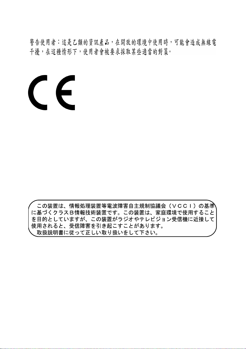
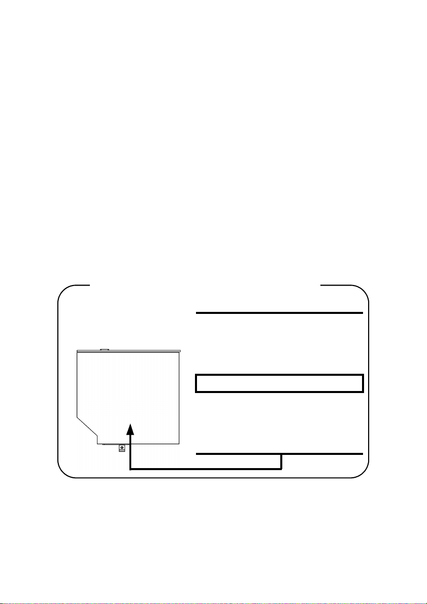
Toshiba Samsung SD-C2712
Location of the required label
PRODUCT IS CERTIFIED BY THE
MANUFACTURER TO COMPLY WITH
DHHS RULES 21 CFR SUBCHAPTER
J APPLICABLE AT THE DATE OF
MANUFACTURE.
MANUFACTURED:
TOSHIBA SAMSUNG STORAGE
TECHNOLOGY CORPORATION 580,
HORIKAWA-CHO, SAIWAI-KU,
KAWASAKI-SHI, KANAGAWA, 2120013, JAPAN
xv
Page 16

CD-RW/DVD-ROM drive safety instructions
CAUTIONS: 1. The drive employs a laser system. To ensure proper use
of this product, please read this instruction manual
carefully and retain for future reference.
Should the unit ever require maintenance, contact an
authorized service location.
2. Use of controls, adjustments or the performance of procedures other than those specified may result in hazardous radiation exposure.
3. To prevent direct exposure to the laser beam, do not try
to open the enclosure.
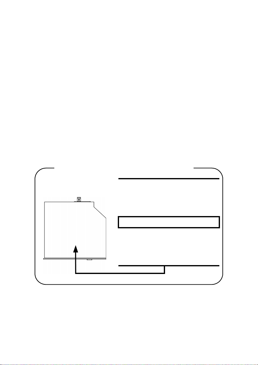
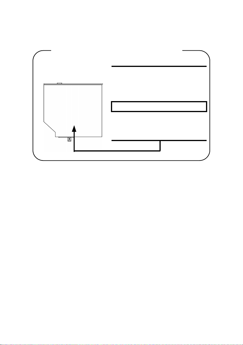
Matsushita UJDA760
Location of the required label
COMPLIES WITHFDA RADIATION
PERFORMANCE STANDARDS, 21
CFR SUBCHAPTER J.
MANUFACTURED:
xvi
Manufactured by
Panasonic Communications Co.,
LTD 1-62, 4-Chome, Minoshima,
Hakata-ku, Fukuoka, JAPAN
Page 17
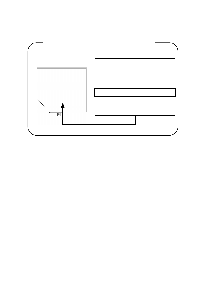
Toshiba Samsung TS-L462A
Location of the required label
PRODUCT IS CERTIFIED BY THE
MANUFACTURER TO COMPLY WITH
DHHS RULES 21 CFR SUBCHAPTER
J APPLICABLE AT THE DATE OF
MANUFACTURE.
MANUFACTURED:
TOSHIBA SAMSUNG STORAGE
TECHNOLOGY CORPORATION 580,
HORIKAWA-CHO, SAIWAI-KU,
KAWASAKI-SHI, KANAGAWA, 2120013, JAPAN
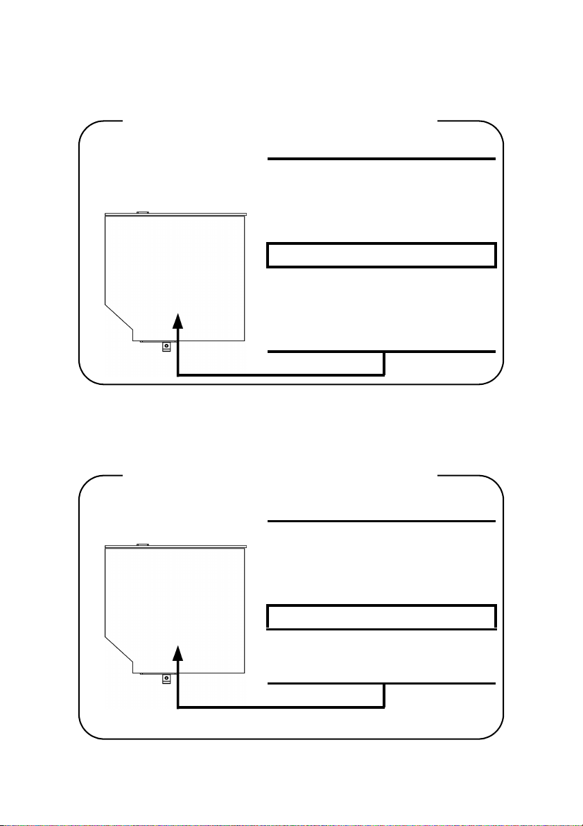
TEAC DW-224E
Location of the required label
CERTIFICATION TISH PRODUCT
COMPLIES WITH DHHS RULES 21
CFR CHAPTER 1, SUBCHAPTER J
APPLICABLE DATE OF MANUFACTURE
MANUFACTURED:
TEAC CORPORATION
3-7-3 NAKA-CHO, MUSASHINO-SHI,
TOKYO, JAPAN
xvii
Page 18
DVD+-R/+-RW drive safety instructions
CAUTIONS: 1. The drive employs a laser system. To ensure proper use
of this product, please read this instruction manual
carefully and retain for future reference.
Should the unit ever require maintenance, contact an
authorized service location.
2. Use of controls, adjustments or the performance of procedures other than those specified may result in hazardous radiation exposure.
3. To prevent direct exposure to the laser beam, do not try
to open the enclosure.
Pioneer DVR-K15TBT
Location of the required label
COMPLIES WITHFDA RADIATION
PERFORMANCE STANDARDS, 21
CFR SUBCHAPTER J.
MANUFACTURED:
xviii
Manufactured by
PIONEER CORPORATION 4-1,
Meguro 1-chome, Meguro-ku,
TOKYO 153-8654, JAPAN
Page 19
DVD Super Multi drive safety instructions
CAUTIONS: 1. The drive employs a laser system. To ensure proper use
of this product, please read this instruction manual
carefully and retain for future reference.
Should the unit ever require maintenance, contact an
authorized service location.
2. Use of controls, adjustments or the performance of procedures other than those specified may result in hazardous radiation exposure.
3. To prevent direct exposure to the laser beam, do not try
to open the enclosure.
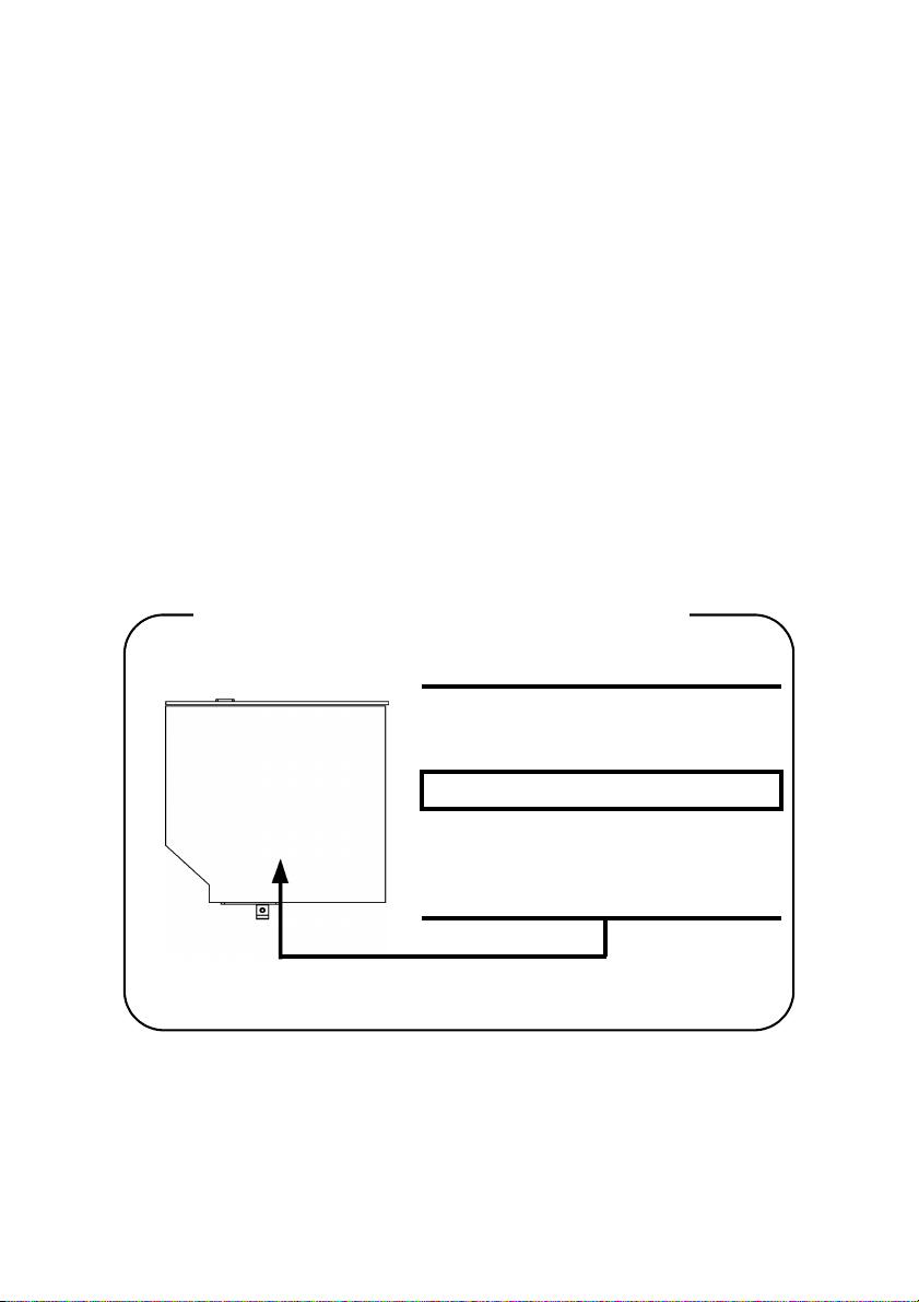
Toshiba Samsung TS-L632A
Location of the required label
PRODUCT IS CERTIFIED BY THE
MANUFACTURER TO COMPLY WITH
DHHS RULES 21 CFR SUBCHAPTER
J APPLICABLE AT THE DATE OF
MANUFACTURE.
MANUFACTURED:
TOSHIBA SAMSUNG STORAGE
TECHNOLOGY CORPORATION 580,
HORIKAWA-CHO, SAIWAI-KU,
KAWASAKI-SHI, KANAGAWA, 2120013, JAPAN
xix
Page 20
Matsushita UJ-830B
Location of the required label
PRODUCT IS CERTIFIED BY THE
MANUFACTURER TO COMPLY WITH
DHHS RULES 21 CFR SUBCHAPTER
J APPLICABLE AT THE DATE OF
MANUFACTURE.
MANUFACTURED:
Manufactured by
Panasonic Communications Co.,
LTD 1-62, 4-Chome, Minoshima,
Hakata-ku, Fukuoka, JAPAN
xx
Page 21

DVD Super Multi (+R Double Layer) drive safety instructions
CAUTIONS: 1. The drive employs a laser system. To ensure proper use
of this product, please read this instruction manual
carefully and retain for future reference.
Should the unit ever require maintenance, contact an
authorized service location.
2. Use of controls, adjustments or the performance of procedures other than those specified may result in hazardous radiation exposure.
3. To prevent direct exposure to the laser beam, do not try
to open the enclosure.
Matsushita UJ-831BT-A
Location of the required label
COMPLIES WITHFDA RADIATION
PERFORMANCE STANDARDS, 21
CFR SUBCHAPTER J.
MANUFACTURED:
Manufactured by
Panasonic Communications Co.,
LTD 1-62, 4-Chome, Minoshima,
Hakata-ku, Fukuoka, JAPAN
xxi
Page 22
TEAC W28E-XXX
Location of the required label
CERTIFICATION TISH PRODUCT
COMPLIES WITH DHHS RULES 21
CFR CHAPTER 1, SUBCHAPTER J
APPLICABLE DATE OF MANUFACTURE
MANUFACTURED:
TEAC CORPORATION
3-7-3 NAKA-CHO, MUSASHINO-SHI,
TOKYO, JAPAN
xxii
Page 23
CLASS 1 LASTER PRODUCT
LASERSCHUTZKLASSE 1
PRODUKT
TO EN 60825
ADVERSEL: USYNLIG
LASERSTRÅLING VED ÅBNING,
NÅR SIKKERHEDSAF-BRYDER
ER UDE AF FUNKTION.
UNDGÅ UDSÆTTELSE FOR
STRÅLING
CAUTION: This appliance contains a laser
system and is classified as a “CLASS 1 LASER
PRODUCT.” To use this model properly, read
the instruction manual carefully and keep this
manual for your future reference. In case of any
trouble with this model, please contact your
nearest “AUTHORIZED service station.” To
prevent direct exposure to the laser beam, do
not try to open the enclosure.
VORSICHT: Dieses Gerät enthält ein LaserSystem und ist als “LASERSCHUTZKLASSE 1
PRODUKT” klassifiziert. Für den richtigen
Gebrauch dieses Modells lesen Sie bitte die
Bedienungsanleitung sorgfältig durch und
bewahren diese bitte als Referenz auf. Falls
Probleme mit diesem Modell auftreten, benachrichtigen Sie bitte die nächste “autorisierte
Service-Vertretung”. Um einen direkten Kontakt mit dem Laserstrahl zu vermeiden darf das
Gerät nicht geöffnet werden.
ADVARSEL: Denne męrking er anbragt udv-
endigt på apparatet og indikerer, at apparatet
arbejder med laserstråler af klasse 1, hviket
betyder, at der anvendes laserstrlier afsvageste
klasse, og at man ikke på apparatets yderside
kan bilve udsat for utilladellg kraftig stråling.
APPARATET BOR KUN ÅBNES AF FAGFOLK
MED SĘRLIGT KENDSKAB TIL APPARATER
MED LASERSTRÅLER!
Indvendigt i apparatet er anbragt den her gengivne advarselsmękning, som advarer imod at
foretage sådanne indgreb i apparatet, at man
kan komme til at udsętte sig for laserstråling.
xxiii
Page 24

OBS! Apparaten innehåller laserkomponent som
avger laserstråining överstigande gränsen för
laserklass 1.
VAROITUS. Suojakoteloa si saa avata. Laite
sisältää laserdiodin, joka lähetää näkymätöntä
silmilie vaarallista lasersäteilyä.
CAUTION: USE OF CONTROLS OR ADJUSTMENTS OR PERFORMANCE OF PROCEDURES OTHER THAN THOSE SPECIFIED IN
THE OWNER’S MANUAL MAY RESULT IN
HAZARDOUS RADIATION EXPOSURE.
VORSICHT: DIE VERWENDUNG VON
ANDEREN STEURUNGEN ODER EINSTELLUNGEN ODER DAS DURCHFÜHREN VON
ANDEREN VORGÄNGEN ALS IN DER BEDIENUNGSANLEITUNG BESCHRIEBEN KÖNNEN GEFÄHRLICHE
STRAHLENEXPOSITIONEN ZUR FOLGE
HABEN.
xxiv
Page 25

Preface
Congratulations on your purchase of the TOSHIBA Satellite M40 computer. This
powerful, lightweight notebook computer is designed to provide years of reliable, high-performance computing.
This manual tells how to set up and begin using your Satellite M40 computer. It
also provides detailed information on configuring your computer, basic operations and care, using optional devices and troubleshooting.
If you are a new user of computers or if you’re new to portable computing, first
read over the Introduction and The Grand Tour chapters to familiarize yourself
with the computer’s features, components and accessory devices. Then read Get-
ting Started for step-by-step instructions on setting up your computer.
If you are an experienced computer user, please continue reading the preface to
learn how this manual is organized, then become acquainted with this manual by
browsing through its pages. Be sure to look over the Special features section of
the Introduction, to learn about features that are uncommon or unique to the
computers and carefully read HW Setup and Passwords. If you are going to
install PC cards or connect external devices such as a printer, be sure to read
Chapter 8, Optional Devices.
Manual contents
This manual is composed of nine chapters, nine appendixes, a glossary, and an
index.
Chapter 1, Introduction, is an overview of the computer’s features, capabilities,
and options.
Chapter 2, The Grand Tour, identifies the components of the computer and
briefly explains how they function.
Chapter 3, Getting Started, provides a quick overview of how to begin operating
your computer and gives tips on safety and designing your work area.
Chapter 4, Operating Basics, includes tips on care of the computer and on using
the Touch Pad, optical media drive, external diskette drive, Wireless LAN,
LANs, Audio/Video controls and internal modem.
Chapter 5, The Keyboard, describes special keyboard functions including the
keypad overlay and hotkeys.
xxv
Page 26

User’s Manual
Chapter 6, Power and Power-Up Modes, gives details on the computer’s power
resources and battery save modes.
Chapter 7, HW Setup and Passwords, explains how to configure the computer
using the HW Setup program. It also tells how to set a password.
Chapter 8, Optional Devices, describes the optional hardware available.
Chapter 9, Troubleshooting, provides helpful information on how to perform
some diagnostic tests, and suggests courses of action if the computer doesn’t
seem to be working properly.
The Appendixes provide technical information about your computer.
The Glossary defines general computer terminology and includes a list of acro-
nyms used in the text.
The Index quickly directs you to the information contained in this manual.
Conventions
This manual uses the following formats to describe, identify, and highlight terms
and operating procedures.
Abbreviations
On first appearance, and whenever necessary for clarity, abbreviations are
enclosed in parentheses following their definition. For example: Read Only
Memory (ROM). Acronyms are also defined in the Glossary.
Icons
Icons identify ports, dials, and other parts of your computer. The indicator panel
also uses icons to identify the components it is providing information on.
Keys
The keyboard keys are used in the text to describe many computer operations. A
distinctive typeface identifies the kejy top symbols as they appear on the keyboard. For example, Enter identifies the Enter key.
xxvi
Page 27

Conventions
Key operation
Some operations require you to simultaneously use two or more keys. We identify such operations by the key top symbols separated by a plus sign (+). For
example, Ctrl + C means you must hold down Ctrl and at the same time press C.
If three keys are used, hold down the first two and at the same time press the
third.
ABC When procedures require an action such as clicking an icon or entering
text, the icon’s name or the text you are to type in is represented in the
type face you see to the left.
Display
ABC
Names of Windows or icons or text generated by the computer that
appears on its display screen is presented in the type face you see to the
left.
Messages
Messages are used in this manual to bring important information to your attention. Each type of message is identified as shown below.
CAUTION: Pay attention! A caution informs you that improper use
of equipment or failure to follow instructions may cause data loss or
damage your equipment.
NOTE: Please read. A note is a hint or advice that helps you make
best use of your equipment.
xxvii
Page 28

User’s Manual
xxviii
Page 29

General Precautions
TOSHIBA computers are designed to optimize safety, minimize strain and withstand the rigors of portability. However, certain precautions should be observed
to further reduce the risk of personal injury, damage to the computer or impared
performance.
Be certain to read the general precautions below and to note the cautions
included in the text of the manual.
Stress injury
Carefully read the Instruction Manual for Safety & Comfort. It contains information on prevention of stress injuries to your hands and wrists than can be caused
by extensive keyboard use. Chapter 3, Getting Started, also includes information
on work space design, posture and lighting that can help reduce physical stress.
Heat injury
◆ Avoid prolonged physical contact with the computer. If the computer is used
for long periods, its surface can become very warm. While the temperature
will not feel hot to the touch, if you maintain physical contact with the computer for a long time (if you rest the computer on your lap, or if you keep
your hands on the palm rest, for example) your skin might suffer low-heat
injury.
◆ If the computer has been used for a long time, avoid direct contact with the
metal plate supporting the I/O ports. It can become hot.
◆ The surface of the AC adaptor can become hot when in use. This condition
does not indicate a malfunction. If you need to transport the AC adaptor, disconnect it and let it cool before moving it.
◆ Do not lay the AC adaptor on a material that is sensitive to heat. The material could be damaged.
Pressure or impact damage
Do not apply heavy pressure to the computer or subject it to strong impact.
Excessive pressure or impact can cause damage to computer components or otherwise cause malfunctions.
xxix
Page 30

User’s Manual
PC card overheating
Some PC cards can become hot with prolonged use. Overheating of a PC card
can result in errors or instability in the PC card operation. Also be careful when
you remove a PC card that has been used for a long time.
Mobile phone
Use of mobile phones can interfere with the audio system. Computer opreation is
not impaired but it is recommended that a distance of 30 cm be maintained
between the computer and a mo-bile phone in use.
Central Processing Unit (“CPU”) Performance Disclaimer
CPU performance in your computer product may vary from specifications under
the following conditions:
◆ Use of certain peripheral products
◆ Use of battery power instead of AC power
◆ Use of certain multimedia, computer generated graphics or video applica-
tions
◆ Use of standard telephone lines or low speed network connections
◆ Use of complex modeling software, such as high end computer aided design
applications
◆ Use of several applications or functionalities simultaneously
◆ Use of computer in areas with low air pressure (high altitude > 1,000 meters
or > 3,280 feet above sea level)
◆ Use of the computer at temperatures outside the range of 5°C to 30°C (41°F
to 86°F) or > 25°C (77°F) at high altitude (all temperature references are
approximate and may vary depending on the specific computer model please refer to your Resource Guide or visit the Toshiba website at
www.pcsupport.toshiba.com for details).
CPU performance may also vary from specifications due to design configuration.
Under some conditions, your computer product may automatically shut-down.
This is a normal protective feature designed to reduce the risk of lost data or
damage to the product when used outside recommended conditions. To avoid
risk of lost data, always make back-up copies of data by periodically storing it on
an external storage medium. For optimum performance, use your computer product only under recommended conditions. Read additional restrictions in bundled
documents. Contact TOSHIBA Service and Support for more information.
xxx
Page 31

Non-applicable Icons
Certain notebook chassis are designed to accommodate all possible configurations for an entire product series. Your selected model may not have all
the features and specifications corresponding to all of the icons or switches
shown on the notebook chassis, unless you have selected all those features.
Wireless LAN/Atheros
For 802.11a, b and g
The transmission speed over the wireless LAN and the distance over which
wireless LAN can reach may vary depending on surrounding electromagnetic environment, obstacles, access point design and configuration, and
client design and software/hardware configurations.
The actual transmission speed will be lower than the theoretical maximum
speed.
For Atheros
To use the Atheros SuperAG™ or SuperG™ function, your client and
access point must support the corresponding feature. Performance of these
functions may vary depending on the format of data transmitted.
LCD
Over a period of time, and depending on the usage of the computer, the brightness of the LCD screen will deteriorate. This is an intrinsic characteristic of LCD
technology.
Copy Protection
Copy protection technology included in certain media may prevent or limit
recording or viewing of the media.
HDD Drive Capacity
1 Gigabyte(GB) means 1000x1000x1000=1,000,000,000 bytes using powers of
10. The computer operating system, however, reports storage capacity using
powers of 2 for the definition of 1 GB=1024x1024x1024=1,073,741,824 bytes,
and therefore may show less storage capacity. Available storage capacity will
also be less if the product includes one or more pre-installed operating systems,
such as Microsoft Operating System and/or pre-installed software applications,
or media content. Actual formatted capacity may vary.
xxxi
Page 32

User’s Manual
SRS
SRS audio enhancements are available in the Microsoft Windows
operation system only.
Images
All images are simulated for purposes of illustration.
Express Media Player
The Express Media Player is not a Windows based application. Battery life will
be less than when using similar applications in the Windows Operating System.
LCD Brightness and Eye Strain
Your LCD display has a brightness approaching that of a TV device. We recommend that you adjust the brightness of your LCD to a comfortable level to prevent possible strain on your eyes.
xxxii
Page 33

Table of Contents
Preface
Manual contents............................................................. xxv
Conventions .................................................................. xxvi
Abbreviations ...............................................................xxvi
Icons ............................................................................xxvi
Keys.............................................................................xxvi
Key operation.............................................................. xxvii
Display ........................................................................xxvii
Messages ...................................................................xxvii
General Precautions
Stress injury ..................................................................xxix
Heat injury .....................................................................xxix
Pressure or impact damage......................................... xxix
PC card overheating ...................................................... xxx
Mobile phone.................................................................. xxx
Central Processing Unit (“CPU”) Performance
Disclaimer....................................................................... xxx
Non-applicable Icons.................................................... xxxi
Wireless LAN/Atheros .................................................. xxxi
Chapter 1 Introduction
Equipment checklist .......................................................1-1
Hardware ......................................................................1-1
Software........................................................................1-2
Features ...........................................................................1-3
Memory.........................................................................1-3
Disks .............................................................................1-4
xxxiii
Page 34

Special features ............................................................1-10
Utilities ...........................................................................1-12
Options ..........................................................................1-14
Chapter 2 The Grand Tour
Front with the display closed ........................................2-1
Left side ...........................................................................2-3
Right side.........................................................................2-4
Back side .........................................................................2-5
Underside ........................................................................2-6
Front with the display open ...........................................2-8
AV Buttons....................................................................2-9
System indicators .........................................................2-10
USB diskette drive ........................................................2-12
Optical Media drive .......................................................2-13
Region codes for DVD drives and media....................2-13
Writable discs .............................................................2-13
DVD-ROM drive..........................................................2-14
CD-RW/DVD-ROM drive ............................................2-14
DVD+-R/+-RW drive (DVD+R DL)..............................2-15
DVD Super Multi drive ................................................2-15
DVD Super Multi drive (DVD+R DL)...........................2-16
AC adaptor.....................................................................2-17
Chapter 3 Getting Started
Setting up your work space ...........................................3-2
General conditions........................................................3-2
Placement of computer.................................................3-2
Seating and posture......................................................3-3
Lighting .........................................................................3-4
Work habits...................................................................3-4
Connecting the AC adaptor ...........................................3-5
Opening the display........................................................3-6
Turning on the power .....................................................3-6
Starting up for the first time...........................................3-7
xxxiv
Page 35

Turning off the power .....................................................3-7
Shut Down mode (Boot mode) .....................................3-7
Hibernation mode .........................................................3-8
Starting Hibernation ......................................................3-9
Automatic Hibernation ..................................................3-9
Standby mode.............................................................3-10
Restarting the computer ..............................................3-11
Restoring the preinstalled software from the Product
Recovery Media.............................................................3-12
Chapter 4 Operating Basics
Using the Touch Pad ......................................................4-1
Using the USB diskette drive.........................................4-2
Connecting 3 1/2" diskette drive ...................................4-2
Disconnecting 3 1/2" diskette drive...............................4-3
Using optical media drives ............................................4-3
Loading discs................................................................4-4
Removing discs ............................................................4-6
AV Button function ........................................................4-8
Express Media Player .....................................................4-8
Writing CDs on CD-RW/DVD-ROM drive ....................... 4-9
Important message (CD-RW/DVD-ROM drive) ............4-9
Before writing or rewriting .............................................4-9
When writing or rewriting ............................................4-10
Disclaimer (CD-RW/DVD-ROM drive) ........................4-11
Writing CD/DVDs on DVD+-R/+-RW drive supporting
DVD+R DL ......................................................................4-11
Important message (DVD+-R/+-RW drive) .................4-11
Before writing or rewriting ...........................................4-11
When writing or rewriting ............................................4-13
Disclaimer (DVD+-R/+-RW drive supporting
DVD+R DL).................................................................4-14
Writing CD/DVDs on DVD Super Multi drive............... 4-14
Important message (DVD Super Multi drive) ..............4-14
Before writing or rewriting ...........................................4-14
xxxv
Page 36

When writing or rewriting ............................................4-16
Disclaimer (DVD Super Multi drive) ............................4-17
Writing CD/DVDs on DVD Super Multi drive supporting
DVD+R DL ......................................................................4-18
Important message (DVD Super Multi drive) ..............4-18
Before writing or rewriting ...........................................4-18
When writing or rewriting ............................................4-20
Disclaimer (DVD Super Multi drive) ............................4-21
RecordNow! Basic for TOSHIBA ................................4-21
Data Verification .........................................................4-22
DLA for TOSHIBA.......................................................4-22
Video...........................................................................4-23
When using WinDVD Creator 2 Platinum: ..................4-23
Media care .....................................................................4-26
CD/DVDs ....................................................................4-26
Diskettes .....................................................................4-27
Using the microphone ..................................................4-27
Modem ...........................................................................4-28
Region selection .........................................................4-28
Properties menu .........................................................4-29
Disconnecting .............................................................4-31
Wireless communications............................................ 4-31
Wireless LAN ..............................................................4-31
Wireless communication Indicator ..............................4-33
LAN.................................................................................4-33
Connecting LAN cable ................................................4-33
Disconnecting LAN cable............................................4-34
Cleaning the computer .................................................4-35
Moving the computer.................................................... 4-35
Heat dispersal ...............................................................4-36
Chapter 5 The Keyboard
Typewriter keys...............................................................5-1
F1 ... F12 function keys ..................................................5-2
Soft keys: Fn key combinations ....................................5-2
xxxvi
Page 37

Emulating keys on enhanced keyboard........................5-2
Hotkeys.........................................................................5-3
Fn Sticky key ................................................................5-7
Windows special keys ....................................................5-7
Keypad overlay ...............................................................5-7
Turning on the overlays ................................................5-7
Arrow mode ..................................................................5-8
Numeric mode ..............................................................5-8
Temporarily using normal keyboard (overlay on) .........5-8
Temporarily using overlay (overlay off).........................5-9
Temporarily changing modes .......................................5-9
Generating ASCII characters .........................................5-9
Chapter 6 Power and Power-Up Modes
Power conditions ............................................................6-1
Power indicators .............................................................6-3
Battery indicator............................................................6-3
DC IN indicator .............................................................6-3
Power indicator .............................................................6-4
Battery types ...................................................................6-4
Battery ..........................................................................6-4
Real time clock battery .................................................6-5
Care and use of the battery pack ..................................6-5
Safety precautions ........................................................6-5
Charging the batteries ..................................................6-8
Monitoring battery capacity.........................................6-10
Maximizing battery operating time ..............................6-11
Retaining data with power off .....................................6-12
Extending battery life ..................................................6-12
Replacing the battery pack ..........................................6-13
Removing the battery pack .........................................6-13
Installing the battery pack ...........................................6-15
Starting the computer by password............................6-15
Power-up modes.........................................................6-16
Windows utilities .........................................................6-16
xxxvii
Page 38

Hotkeys.......................................................................6-16
Panel power on/off......................................................6-16
System Auto Off..........................................................6-16
Chapter 7 HW Setup and Passwords
HW Setup .........................................................................7-1
Accessing HW Setup ....................................................7-1
HW Setup window ........................................................7-2
Chapter 8 Optional Devices
Cards/memory ..............................................................8-1
Power devices ..............................................................8-1
Peripheral devices ........................................................8-1
Other.............................................................................8-1
PC cards ..........................................................................8-2
Installing a PC card.......................................................8-2
Removing a PC card.....................................................8-3
Express Card...................................................................8-4
Installing an Express Card............................................8-4
Removing an Express Card..........................................8-5
Multiple Digital Media Card Slot ....................................8-6
Installing a SD/MS/MS Pro/SM/MMC/xD card..............8-6
Removing a SD/MS/MS Pro/SM/MMC/xD card............8-7
Memory expansion .........................................................8-8
Installing memory module.............................................8-8
Removing memory module.........................................8-10
Additional battery pack (12 Cell and 6 Cell) ...............8-11
Additional AC adaptor ..................................................8-11
USB FDD Kit ..................................................................8-11
Parallel printer...............................................................8-11
External monitor ...........................................................8-12
Television ......................................................................8-13
i.LINK (IEEE1394) ......................................................... 8-13
Precautions.................................................................8-14
Connecting..................................................................8-14
xxxviii
Page 39

Disconnecting .............................................................8-15
Security lock..................................................................8-15
Chapter 9 Troubleshooting
Problem solving process ...............................................9-1
Preliminary checklist .....................................................9-1
Analyzing the problem ..................................................9-2
Hardware and system checklist ....................................9-3
System start-up.............................................................9-3
Self test.........................................................................9-4
Power............................................................................9-4
Password ......................................................................9-7
Keyboard ......................................................................9-7
LCD panel.....................................................................9-7
Hard disk drive..............................................................9-8
DVD-ROM drive............................................................9-8
CD-RW/DVD-ROM drive ............................................9-10
DVD+-R/+-RW drive ...................................................9-11
DVD Super Multi drive ................................................9-13
Diskette drive ..............................................................9-14
Infrared port ................................................................9-15
Printer .........................................................................9-15
Pointing device ...........................................................9-16
Touch Pad ..................................................................9-16
USB mouse.................................................................9-17
PC card.......................................................................9-18
SD/MS/SM/MMC/xD card ...........................................9-19
Monitor........................................................................9-19
Sound system .............................................................9-20
TV output signal..........................................................9-20
USB ............................................................................9-21
Modem........................................................................9-22
Standby/Hibernation ...................................................9-23
LAN.............................................................................9-24
Wireless LAN ..............................................................9-24
xxxix
Page 40

Bluetooth.....................................................................9-25
i.LINK (IEEE1394) ......................................................9-25
TOSHIBA support .........................................................9-26
Before you call ............................................................9-26
Appendix
Appendix A
Specifications................................................................. A-1
Appendix B
Display Controller and Modes ...................................... B-1
Appendix C
AT Commands................................................................ C-1
Appendix D
S-registers ...................................................................... D-1
Appendix E
V.90/V.92 ......................................................................... E-1
Appendix F
Internal Modem Guide ....................................................F-1
Appendix G
Wireless LAN.................................................................. G-1
Appendix H
AC Power Cord and Connectors .................................. H-1
Appendix I
Parts Numbers .................................................................I-1
Glossary
Index
xl
Page 41

Chapter 1
Introduction
This chapter provides an equipment checklist, and it identifies the computer’s
features, options and accessories.
CAUTION: Some of the features described in this manual may not
function properly if you use an operating system that was not preinstalled by TOSHIBA.
Equipment checklist
Carefully unpack your computer. Save the box and packing materials for future
use.
Hardware
Check to make sure you have all the following items:
❑ Satellite M40 Portable Personal Computer
❑ Universal AC adaptor and power cord
❑ USB diskette drive (Provided with some models)
❑ Modular cable (Provided with some models)
I
NTRODUCTION
1-1
Page 42

User’s Manual
Software
Windows XP Professional/Home Edition Service Pack 2
◆ The following software is preinstalled:
NTRODUCTION
I
• Microsoft
• Modem Driver
• Display Drivers for Windows
• TOSHIBA Utilities
• Wireless LAN driver (Can be used only for Wireless LAN models)
• Sound Driver for Windows
• DVD Video Player
•LAN Drivers
• Bluetooth Driver (Can be used only for Bluetooth models)
• Pointing Device Driver
• TOSHIBA Power Saver
• TOSHIBA User’s Manual
• TOSHIBA Assist
• TOSHIBA ConfigFree
• TOSHIBA Touch and Launch
• TOSHIBA Touch Pad On/Off Utility
• TOSHIBA PC Diagnostic Tool
• TOSHIBA Zooming Utility
• TOSHIBA SD Memory Boot Utility
• TOSHIBA Controls
• TOSHIBA Virtual Sound
◆ Documentation:
• Satellite M40 Resorce Guide
• Microsoft Windows XP manual package
• Instruction Manual for Safety & Comfort
• End User License Agreement
◆ Product Recovery Media
®
Windows XP Home Edition, Professional
1-2
Page 43

Features
Features
The computer uses TOSHIBA’s advanced Large Scale Integration (LSI), Comple-mentary Metal-Oxide Semiconductor (CMOS) technology extensively to
provide compact size, minimum weight, low power usage, and high reliability.
This computer incorporates the following features and benefits:
Processor
Built-in
Built-in
The computer is equipped with an Intel
processor, on-die 32KB instruction L1 cache and 2MB
L2 cache memory.
®
Intel
Pentium® M Processor 730
®
Intel
Pentium® M Processor 740
®
Pentium® M Processor 750
Intel
®
Pentium® M Processor 760
Intel
®
Pentium® M Processor 770
Intel
The computer is equipped with an Intel
processor, on-die 32KB instruction L1 cache and 1MB
L2 cache memory.
®
Intel
Celeron® M Processor 350
®
Celeron® M Processor 360
Intel
®
Celeron® M Processor 370:
Intel
®
Note: Intel
Celeron
Pentium® M Processor and Intel®
®
M Processor can support Execute-
Disable Bit.
This function is available when it is setting to Available on BIOS setup menu (Default setting is NotAvailable). You can enter BIOS setup menu when you
turn on the power with pressing ESC key.
®
Pentium® M
®
Celeron® M
I
NTRODUCTION
Memory
Level 2 cache
Video RAM Up to 128 MB integrated solution shares with main
Slots PC2700 128 MB or 256 MB or 512 MB or 1024 MB
memory modules can be installed in the two memory
slots for a maximum of 2048 MB system memory.
A 1 MB (Intel
®
Celeron® M)/2 MB (Intel® Pentium®
M) level 2 cache is provided to maximize performance.
memory for intel 915GM/910GML. External 32/64/128
MB VGA DDR RAM for ATI MOBIRITY™
RADEON™ X300/X600 or nVIDIA Geforce Go 6600/
6250.
1-3
Page 44

User’s Manual
Disks
Hard disk drive The computer has an integrated, 2 1/2" hard disk drive
NTRODUCTION
I
Diskette drive 3 1/2" 1.44-megabyte or 720-kilobyte connects to the
DVD-ROM drive A full-size, DVD-ROM drive module lets you run either
CD-RW/DVD-
DVD +-R/+-RW
ROM drive
drive
(HDD) for nonvolatile storage of data and software. It
comes in the following sizes.
• 40.0 GB (37.26 billion bytes)
• 60.0 GB (55.89 billion bytes)
• 80.0 GB (74.52 billion bytes)
• 100.0 GB (93.15 billion bytes)
• 120.0 GB (111.78 billion bytes)
USB port. (Windows
byte diskettes.)
digital versatile or compact disks without using an adaptor. It runs DVD-ROMs at maximum 8 speed and CDROMs at maximum 24 speed. This drive supports the
same formats as the CD-ROM drive plus the following:
• DVD-ROM • DVD-Video
Some models are equipped with a full-size, CD-RW/
DVD-ROM drive module that lets you run CD/DVDs
without using an adaptor. It reads DVD-ROMs at maximum 8 speed and CD-ROMs at maximum 24 speed. It
writes CD-R at up to 24 speed and CD-RW at up to 24
speed. See Chapter 4, Operating Basics, for details. For
reading, this drive supports the same formats as the
DVD-ROM drive.
Some models are equipped with a full-size DVD +-R/+RW drive module that lets you record data to rewritable
CD/DVDs as well as run either 12 cm (4.72") or 8 cm
(3.15") CD/DVDs without using an adaptor. It reads
DVD-ROMs at maximum 8 speed and CD-ROMs at
maximum 24 speed. It writes CD-R at up to 24 speed,
CD-RW at up to 24 speed, DVD-R at up to 8 speed and
DVD-RW at maximum 4 speed.
DVD+R at up to 8 speed and DVD+RW at maximum 4
speed. This drive supports the same formats as the
DVD-ROM drive.
®
XP does not support 720-kilo-
1-4
Page 45

DVD Super Multi
drive
Features
• DVD-ROM • DVD-Video
• DVD-R • DVD-RW
• DVD+R • DVD+RW
• CD-DA • CD-Text
• Photo CD (single/multi-session)
• CD-ROM Mode 1, Mode 2
• CD-ROMXA Mode 2 (Form1, Form2)
• Enhanced CD (CD-EXTRA)
• CD-G (Audio CD only)
• Addressing Method 2
Some models are equipped with a full-size DVD Super
Multi drive module that lets you record data to rewritable CD/DVDs as well s run either 12 cm (4.72") or 8
cm (3.15") CD/DVDs without using an adaptor. It reads
DVD-ROMs at maximum 8 speed and CD-ROMs at
maximum 24 speed. It writes CD-R at up to 16 speed,
CD-RW at up to 8speed, DVD-R at up to 4 speed and
DVD-RW and DVD-RAM at maximum 2 speed.
DVD+R/+RW at up to 2.4 speed. This drive supports
the same formats as the DVD-ROM drive.
• DVD-ROM • DVD-Video
• DVD-R • DVD-RW
• DVD+R • DVD+RW
• DVD-RAM
• CD-DA • CD-Text
• Photo CD (single/multi-session)
• CD-ROM Mode 1, Mode 2
• CD-ROMXA Mode 2 (Form1, Form2)
• Enhanced CD (CD-EXTRA)
• CD-G (Audio CD only)
• Addressing Method 2
I
NTRODUCTION
1-5
Page 46

User’s Manual
Display
The computer’s LCD panel supports high-resolution video graphics. The screen
can be set at a wide range of viewing angles for maximum comfort and readability.
NTRODUCTION
I
Graphics controller Graphics controller maximizes display performance.
Built-in Thin-film transistor color LCD is available in three
sizes:
• 15.4" WXGA, 1280 horizontal x 800 vertical pixels
• 15.4" WXGA-CSV, 1280 horizontal x 800 vertical pixels
• 15.4" WSXGA+, 1680 horizontal x 1050 vertical pixels
Refer to Appendix B for more information.
Keyboard
Built-in
85 keys or 86 keys, compatible with IBM
keyboard, embedded numeric overlay, dedicated cursor
control, and keys. See Chapter 5, The Key-
board, for details.
®
enhanced
Pointing Device
Power
Ports
1-6
Built-in A Touch Pad and control buttons in the palm rest enable
control of the on-screen pointer.
Battery pack The computer is powered by one rechargeable lithium-
ion battery pack.
RTC battery The internal RTC battery backs up the Real Time Clock
(RTC) and calendar.
AC adaptor The universal AC adaptor provides power to the system
and recharges the batteries when they are low. It comes
with a detachable power cord. Because it is universal, it
can receive a range of AC voltage between 100 and 240
volts.
Headphone Enables connection of a stereo headphone.
Microphone Enables connection of a monaural microphone.
Page 47

Features
Bulit-in Microphone A built-in microphone lets you record sounds into your
applications.
Parallel Parallel printer or other parallel device (ECP compati-
ble). (Provided with some models)
Infrared
External monitor 15-pin, analog VGA port supports VESA DDC2B com-
Universal Serial Bus
(USB2.0)
i.LINK™
(IEEE 1394)
Video Out Jack This S-Video out port lets you transfer NTSC or PAL
This infrared port is compatible with Infrared Data Association (IrDA 1.1) Fast InfraRed (FIR) standards. It enables
cableless 4 Mbps data transfer with IrDA 1.1 compatible
external devices. (Provided with some models)
patible functions.
Three Universal Serial Bus (USB) enables chain con-
nection of a number of USB-equipped devices to one
port on your computer.
This port enables high-speed data transfer directly from
external devices such as digital video camera.
(Provided with some models)
data to external devices.
Slots
I
NTRODUCTION
PC card A PC card slot accommodates:
One 5 mm Type II card
Refer to Chapter 8, Optional Devices, for details
Multiple Digital
Media Card
Express card This slot allows you to install a Express Card™/34 or
This slot lets you easily transfer data from devices, such
as digital cameras and Personal Digital Assistants, that
use flash memory (SD/MS/MS Pro/SM/MMC/xD memory cards). (Provided with some models)
Express Card™/54 to expand functionality.
(Provided with some models)
Multimedia
Sound System Sound Blaster™ Pro™ and Windows Sound System
compatible sound system provides internal speaker as
well as jacks for an external microphone and headphone. It also has a volume control dial.
1-7
Page 48

User’s Manual
S-Video Out Port This S-Video out port lets you transfer NTSC or PAL
Communications
NTRODUCTION
I
Wireless LAN Some computers in this series are equipped with a Wire-
data to external devices. See Chapter 8, Television, for
details.
Modem An internal modem provides capability for data and fax
communication. It supports V.90 (V.92). Refer to V.90
section in Appendix E. The speed of date transfer and
fax depends on analog telephone line conditions. It has a
modem jack for connecting to a telephone line. It is preinstalled as a standard device in some markets. Both of
V.90 and V.92 are supported only in USA, Canada and
Australia. Only V.90 is available in other regions.
LAN The computer is equipped with a LAN card that sup-
ports Ethernet LAN (10 Mbit/s, 10BASE-T), Fast Ethernet LAN (100 Mbit/s, 100BASE-TX) and Giga-bit. It is
preinstalled as a standard device in some markets.
less LAN mini-PCI card that is compatible with other
LAN systems based on Direct Sequence Spread Spectrum/Orthogonal Frequency Division Multiplexing
radio technology that complies with the IEEE 802.11
Standard (Revision A, B or G), and Turbo Mode.
• Automatic Transmit Rate Select mechanism in the
transmit range of 54, 48, 36, 24, 18, 12, 9 and 6 Mbit/s
(Revision A/B, B/G, A/B/G combo type).
• Automatic Transmit Rate Select mechanism in the
transmit range of 11, 5.5, 2 and 1 Mbit/s (Revision B).
• Automatic Transmit Rate Select mechanism in the
transmit range of 108, 96, 72, 48, 36, 24, 18, and 12
Mbit/s (Turbo Mode, Revision A/B/G combo type).
• Frequency Channel Selection (5 GHz: Revision A/2.4
GHz: Revision B/G).
• Roaming over multiple channels.
• Card Power Management.
• Atheros Super G™ or Super AG™
(Atheros module type).
technology
1-8
Page 49

• Wired Equivalent Privacy (WEP) data encryption,
based on 152 bit encryption algorithm (Atheros module type).
• Wired Equivalent Privacy (WEP) data encryption,
based on 128 bit encryption algorithm(Intel module
type).
• Advanced Encryption Standard (AES) data encryption, based on 256 bit encryption algorithm (Atheros
module type).
Bluetooth Some computers in this series are equipped with Blue-
tooth functions. Bluetooth wireless technology eliminates the need for cables between electronic devices
such as computers and printers. Bluetooth provides fast,
reliable, and secure wireless communication in a small
space.
Wireless Communi-
cation Switch
This switch turns the Wireless LAN and Blurtooth function on and off. (Provided with some models)
Security
Security lock slot Connects an optional security lock to anchor the com-
puter to a desk or other large object.
Features
I
NTRODUCTION
Software
Operating System
TOSHIBA Utilities A number of utilities and drivers are preinstalled to
Plug and Play When you connect an external device to the computer or
Windows
able. Refer to the preinstalled software section at the
front of this chapter.
make your computer more convenient to use. Refer to
the Utilities section in this chapter.
when you install a component, Plug and Play capability
enables the system to recognize the connection and
make the necessary configurations automatically.
®
XP Professional or Home Edition is avail-
1-9
Page 50

User’s Manual
Special features
The following features are either unique to TOSHIBA computers or are
advanced features, which make the computer more convenient to use.
NTRODUCTION
I
Display automatic
HDD automatic
System automatic
Standby/Hiberna-
Keypad overlay A ten-key pad is integrated into the keyboard. Refer to
Power on password Two levels of password security, supervisor and user,
Intelligent power
Battery save mode This feature lets you save battery power. You can spec-
Hotkeys Key combinations let you quickly modify the system
configuration directly from the keyboard without running a system configuration program.
This feature automatically cuts off power to the internal
power off
power off
Instant security A hot key function blanks the screen and disables the
supply
display when there is no keyboard input for a time specified. Power is restored when any key is pressed. You
can specify the time in the Monitor power off item of
the Basic Setup tab in TOSHIBA Power Saver.
This feature automatically cuts off power to the hard
disk drive when it is not accessed for a time specified.
Power is restored when the hard disk is accessed. You
can specify the time in the HDD Power off item of the
Basic Setup tab in TOSHIBA Power Saver.
This feature automatically shuts down the system in
standby mode or Hibernation mode when there is no
tion
input or hardware access for a time specified. You can
specify the time and select either System Standby or
System hibernation in the System standby and System
item of the Basic Setup tab in TOSHIBA Power Saver.
the Keypad overlay section in Chapter 5, The Keyboard,
for instructions on using the keypad overlay.
are available to prevent unauthorized access to your
computer.
computer providing data security.
A microprocessor in the computer’s intelligent power
supply detects the battery’s charge and calculates the
remaining battery capacity. It also protects electronic
components from abnormal conditions, such as voltage
overload from an AC adaptor. You can monitor remaining battery capacity. Use the Battery remaining item in
TOSHIBA Power Saver.
ify the Power Save Mode in the Profile item in
TOSHIBA Power Saver.
1-10
Page 51

Special features
Panel power on/off This feature turns power to the computer off when the
display panel is closed and turns it back on when the
panel is opened. You can specify the setting in the When
I close the lid item of the Setup Action tab in TOSHIBA
Power Saver.
Low battery auto-
matic hibernation
Heat dispersal To protect from overheating, the CPU has an internal
Hibernation This feature lets you turn off the power without exiting
Standby If you have to interrupt your work, you can turn off the
When battery power is exhausted to the point that computer operation cannot be continued, the system automatically enters Hibernation and shuts down. You can
specify the setting in the Setup Action tab in TOSHIBA
Power Saver.
temperature sensor. If the computer’s internal temperature rises to a certain level, the cooling fan is turned on
or the processing speed is lowered. Use the Cooling
Method item of the Basic Setup tab in TOSHIBA Power
Saver.
Maximum
Performance
Battery
optimized
from your software. The contents of main memory are
saved to the hard disk, when you turn on the power
again, you can continue working right where you left
off. Refer to the Turning off the power section in Chapter 3, Getting Started, for details.
power without exiting from your software. Data is
maintained in the computer’s main memory. When you
turn on the power again, you can continue working right
where you left off.
Turns on fan first, then if necessary
lowers CPU processing speed.
Lowers the CPU processing speed
first, then if necessary turns on the
fan.
I
NTRODUCTION
1-11
Page 52

User’s Manual
Utilities
This section describes preinstalled utilities and tells how to start them. For details
on operations, refer to each utility’s online manual, help files or readme.txt files.
NTRODUCTION
I
TOSHIBA Assist TOSHIBA Assist is a graphical user interface that pro-
vides easy access to help and services.
TOSHIBA Power
Saver
HW Setup This program lets you customize your hardware settings
Fn-esse This Windows program lets you define your own “short-
DVD Video Player The DVD Video Player is used to play DVD-Video. It
TOSHIBA Zoom-
ing Utility
RecordNow! Basic
for TOSHIBA
DLA for TOSHIBA DLA (Drive Letter Access) is the packet writing soft-
TOSHIBA PC Diag-
nostic Tool
To access this power savings management program,
click the Control Panel and select the TOSHIBA Power
Saver icon.
according to the way you work with your computer and
the peripherals you use. To start the utility, click the
Windows Start button and click Control Panel. In the
Control Panel, select the TOSHIBA HW Setup icon.
cut” keys to quickly launch applications and speed your
work in Windows. To start the utility, click the Windows
Start button, point to All Programs, point to TOSHIBA,
point to Utilities and click Fn-esse.
has an on-screen interface and functions. Click Start,
point to All Programs, point to InterVideo WinDVD 5,
then click InterVideo WinDVD 5.
This utility allows you to enlarge or reduce the icon size
on the desktop or the application window.
You can create CD/DVDs in several formats including
audio CDs that can be played on a standard stereo CD
player and data CD/DVDs to store the files and folderson your hard disk drive. This software can be used on a
model with CD-RW/DVD-ROM drive, DVD-R/-RW
drive, DVD+-R/+-RW drive and DVD Super Multi
drive.
ware which provides the function which writes files
and/or folders to DVD+RW, DVD-RW or CD-RW disc
via a drive letter like a floppy disk or other removable
disks.
TOSHIBA PC Diagnostic Tool displays the basic information on PC, and the test of built-in devices can also
be performed. You can boot TOSHIBA PC Diagnostic
Tool from the menu bar as follows [Start] - [All Programs] - [TOSHIBA] -[Utilities] [PC Diagnostic Tool]
1-12
Page 53

Utilities
TOSHIBA Config-
Free
TOSHIBA Touch
Pad On/Off Utility
TOSHIBA Touch
and Launch
TOSHIBA Controls This utility lets you customize Internet button and CD/
Bluetooth
TOSHIBA Stack
TOSHIBA SD
Memory Boot
Utility
ConfigFree is a suite of utilities to allow easy control of
communication device and network connections. ConfigFree also allows you to find communication problems and create profiles for easy switching between
location and communication networks.
You can boot ConfigFree from the menu bar as follows.
[Start] - [All Programs] - [TOSHIBA]-[Networking]-
[ConfigFree]
Pressing Fn+F9 in a windows environment enables or
disables the Touch Pad function. When you press these
hot keys, the current setting will change and be displayed as an icon.
TOSHIBA Touch and Launch is a tool that allows you
to perform various tasks easily using Touch pad.
TOSHIBA Touch and Launch is useful in the following
conditions.
• To open a file located on the desktop whose icon is
obscured by a window.
• To open a page contained in the Internet Explorer
Favorites menu.
• To display the list of currently open windows and
change the active window.
Also TOSHIBA Touch and Launch provides the following functions by customizing the settings.
• To open a file stored in a predefined folder.
• To quickly launch your frequently used applications
which have been registered.
DVD button: you can assign applications or several
actions to these buttons (Internet default browser and
CD/DVD are assigned to each button by default).
This software enables communication between remote
Bluetooth devices.
Note: Bluetooth cannot be used in models that
do not have a Bluetooth module installed.
The TOSHIBA SD memory boot utility is a utility
which can create SD memory card to a boot disk.
I
NTRODUCTION
1-13
Page 54

User’s Manual
Options
You can add a number of options to make your computer even more powerful
and convenient to use. The following options are available:
Memory expansion Two memory expansion slots are available for installing
NTRODUCTION
I
Battery pack
(Black)
AC adaptor If you use your computer at more than one site, it may
USB diskette drive A 3 1/2" diskette drive accommodates 1.44-megabyte or
Security lock A slot is available to attach a security cable to the com-
128 MB or 256 MB or 512 MB or 1024 MB memory
modules. The modules are PC2700, 200-pin, SO Dual
In-line (SO-DIMM).
An additional battery pack 12 cells Type (PA3400U-1
BAS/PA3400U-1 BRS), 6 cells Type (PA3399U-1 BAS/
PA3399U-1 BRS) can be purchased from your
TOSHIBA dealer. The battery pack is identical to the
one that came with your computer. Use it as a spare or
replacement.
be convenient to purchase an additional AC adaptor for
each site so you will not have to carry the adaptor with
you.
720-kilobyte diskettes. It connects to a USB port. (Win-
®
dows
XP does not support 720-kilobyte diskettes.)
puter to deter theft.
1-14
Page 55

The Grand Tour
Chapter 2
This chapter identifies the various components of your computer. Become familiar with each component before you operate the computer.
Front with the display closed
Figure 2-1 shows the computer’s front with its display panel in the closed position.
MULTIPLE
D
LAY LATCH
D
IGITAL MEDIA
CARD SLOT
MULTIPLE
D
IGITAL
M
EDIA
CARD
INDICATOR
SYSTEM INDICATORS
MICROPHONE
Figure 2-1 Front of the computer with display closed
Display latch This latch secures the LCD panel in its closed position.
Microphone jack A standard 3.5 mm mini microphone jack enables con-
Headphone jack A standard 3.5 mm mini headphone jack enables con-
HEADPHONE
ISP
INFRARED PORT
Slide the latch to open the display.
nection of a monaural microphone or other device for
audio input.
nection of a stereo headphone (16 ohm minimum) or
other device for audio output. When you connect headphones, the internal speaker is automatically disabled.
VOLUME CONTROL
WIRELESS
C
OMMUNICATION
S
WITCH
T
HE
G
RAND
T
OUR
2-1
Page 56

User’s Manual
Volume control Use this dial to adjust the volume of the system speaker
Infrared port This infrared port is compatible with Infrared Data
Wireless commu-
OUR
nication switch
T
RAND
G
HE
T
CAUTION: Set the switch to off in airplanes and hospitals. Check
the Wireless communication indicator. It will stop glowing when the
wireless communication.
and headphones.
Association (IrDA 1.1) standards. It enables cableless 4
Mbps, 1.152 Mbps, 115.2 Kbps, 57.6 Kbps, 38.4 Kbps,
19.2 Kbps or 9.6 Kbps data transfer with IrDA 1.1 com-
patible external devices. (Provided with some models)
Slide this switch toward the left of the computer to turn
on Wireless communication. Slide it toward the right of
the computer to turn off the functions. (Provided with
some models)
Multiple Digital
Media Card Slot
CAUTION: Keep foreign objects out of the Multiple Digital Media
Card Slot. A pin or similar object can damage the computer’s circuitry.
Multiple Digital
Media Card
Indicator
System Indica-
tors
Slide the cover toward the left to access the Multiple
Digital Media Card Slot of your computer. This slot lets
you easily transfer data from devices, such as digital
camera and PDA, that use flash memory (SD/MS/MS
Pro/SM/MMC/xD memory cards). (Provided with some
models)
This LED glows blue when the computer is accessing
the memory card. (Provided with some models)
Four LEDs let you monitor the DC IN, Power status,
Main battery and Disk. Details are in the System indicators sections.
2-2
Page 57

Left side
Figure 2-2 shows the computer’s left side.
Left side
FAN VENT
PARALLEL PORT
Parallel port This Centronics-compatible, 25-pin parallel port is used
External monitor
Fan vent Provides air flow for the fan.
CAUTION: Be careful not to block the fan vent. Also be careful to
keep foreign objects out of the vents. A pin or similar object can
damage the computer’s circuitry.
Universal Serial
Bus port
EXTERNAL
MONITOR PORT
Figure 2-2 The left side of the computer
to connect a parallel printer or other parallel device.
This port supports Extended Capabilities Port (ECP)
standard. (Provided with some models)
This 15-pin port lets you connect an external monitor.
port
The Universal Serial Bus (USB) port comply with USB
2.0 standards,which enables data transfer speeds 40
times faster than the USB 1.1 standards. (The port also
support USB 1.1.)
USB PORT
EXPRESS CARD
SLOT
PC CARD
SLOT
T
HE
G
RAND
T
OUR
CAUTION: Keep foreign objects out of the USB connectors. A pin
or similar object can damage the computer’s circuitry.
2-3
Page 58

User’s Manual
Note: Operation of all functions of all USB devices has not been
confirmed. some functions might not execute properly.
PC Card Slot The PC card slot can accommodate one 5 mm PC card
(Type II). The slot supports 16-bit PC card and 32-bit
CardBus PC card.
CAUTION: Keep foreign objects out of the PC card slot. A pin or
similar object can damage the computer’s circuitry.
OUR
T
RAND
Express Card The computer provides Express Card slot on its left
side, which allows you to install an additional Express
card. (Provided with some models)
G
Right side
HE
T
Figure 2-3 shows the computer’s right side.
I.LINK (IEEE 1394) PORT
OPTICAL MEDIA DRIVE
Figure 2-3 The right side of the computer
Optical Media
Drive
Universal Serial
Bus Ports
CAUTION: Keep foreign objects out of the USB connectors. A pin
or similar object can damage the computer’s circuitry.
Note: Operation of all functions of all USB devices has not been
confirmed. some functions might not execute properly.
2-4
A DVD-ROM drive, CD-RW/DVD-ROM drive,
DVD+-R/+-RW drive, DVD Super Multi drive.
The two Universal Serial Bus (USB) port comply with
USB Serial 2.0 standards, which enables data transfer
speeds 40 times faster than the USB 1.1 standards. (The
port also support USB 1.1)
USB PORTS
Page 59

Back side
i.LINK (IEEE
1394) Port
Note: When multiple IEEE1394 devices are connected to a PC, the
devices may not correctly be identified. This problem may occur
when Windows
when the power to the IEEE1394 devices is turned on before the PC
is turned on. If it occurs, disconnect the IEEE1394 cables and then
reconnect them.
Connect an external device, such as a digital video camera to this port for high-speed data transfer. Some models are equipped with a i.LINK port. (Provided with
some models)
®
XP is restarted while the devices are connected or
Back side
Figure 2-4 shows the computer’s back side.
MODEM JACK
SECURITY LOCK SLOT
T
HE
G
RAND
T
OUR
VIDEO-OUT
JACK
Video-out jack Plug a 4-pin S-Video connector into this jack.
Modem jack In areas where an internal modem is installed as stan-
JACK
LAN
Figure 2-4 The computer’s back side
dard equipment, there is a modem jack that lets you use
a modular cable to connect the modem directly to a telephone line. The modem is not supported in some marketing regions.
DC IN 15V
2-5
Page 60

User’s Manual
LAN jack This jack lets you connect to a LAN. The adaptor has
built-in support for Ethernet LAN (10 megabits per second, 10BASE-T), Fast Ethernet LAN (100 megabits per
second, 100BASE-Tx) and Giga-bit. The LAN has two
indicators. See Chapter 4, Operating Basics, for
detailes.
DC IN 15V The AC adaptor connects to this socket. Use only the
model of AC adaptor that comes with the computer.
OUR
T
Security lock slot A security cable attaches to this slot. The optional secu-
RAND
Using the wrong adaptor can damage your computer.
rity cable anchors your computer to a desk or other large
object to deter theft.
G
HE
T
Underside
Figure 2-5 shows the underside of the computer. Make sure the display is closed
before turning over your computer.
BATTERY
BATTERY P ACK
L
OCK
PACK
BATTERY
R
ELEASE LATCH
MEMORY
MODULE COVER
2-6
Figure 2-5 The underside of the computer
Page 61

Underside
Battery pack The battery pack powers the computer when the AC
adaptor is not connected. The Batteries section in Chapter 6, Power and Power-Up Modes, describes how to
access the battery pack. Additional battery packs can be
purchased from your TOSHIBA dealer to extend the
computer’s battery operating time.
Battery pack
cover latch
Battery lock Slide the battery pack lock to unlocked position to free
Memory module
cover
Slide this latch to release the battery pack.
This latch moves only when the computer is upside
down.
the battery latch.
This cover protects two memory module sockets. One
or two modules are preinstalled.
T
HE
G
RAND
T
OUR
2-7
Page 62

User’s Manual
Front with the display open
Figure 2-6 shows the front of the computer with the display open. To open the
display, slide the display latch on the front of the computer and lift the display
up. Position the display at a comfortable viewing angle.
DISPLAY SCREEN
DISPLAY HINGE
OUR
T
DISPLAY HINGE
RAND
G
HE
T
Stereo Speaker The speaker emits sound generated by your software as
STEREO SPEAKER
(R
IGHT)
STEREO SPEAKER
(L
EFT)
POWER
BUTTON
INTERNET
BUTTON
CD/DVD BUTTON
TOUCH PAD
C
ONTROL BUTTONS
TOUCH PAD
SYSTEM
I
NDICATORS
Figure 2-6 The front with the display open
Display screen
The full-color LCD displays high-contrast text and
graphics The computer’s LCD consist of one of below:
15.4" WXGA, 1280 horizontal x 800 vertical pixels.
15.4" WXGA-CSV, 1280 horizontal x 800 vertical pixels.
15.4" WSXGA+, 1680 horizontal x 1050 vertical pixels.
The computer has a Thin-Film Transistor (TFT) display.
Refer to
Appendix B
.
When the computer operates on power through the AC
adaptor, the display screen’s image will be somewhat
brighter than when it operates on battery power. The
lower brightness level is intended to save battery power.
Display Hinge The display hinge holds the display screen at easy-to-
view angles.
well as audio alarms, such as low battery condition, generated by the system.
2-8
Page 63

Front with the display open
Power button Press the power button to turn the computer’s power on
and off. The Power button LED indicates the status.
Touc h Pad Moves the pointer and selects or activates items on the
screen. Can be set to perform other mouse functions,
such as scrolling, selecting, and double-clicking.
Touc h Pad
Control Buttons
Function like the left and right buttons on an external
mouse.
AV Buttons
Six buttons are provided with some models.
Available for use: Internet, CD/DVD, Play/Pause, Stop, Previous, Next.
These buttons allow you to manage Audio/Video, run applications and access utilities.
Refer to the AV button function section in Chapter 4,
Internet button Press this button to launch an Internet browser. If the
computer’s power is off, you can press this button to
turn on the computer’s power and launch the browser
automatically in one step.
CD/DVD button Pressing this button in the power-off condition will run
Express Media Player (DVD) or Express Media Player
(CD). Once Express Media Player (DVD) or Express
Media Player (CD) is launched, Power indicator turns
on and the audio button is enable. Meanwhile, when
Express Media Player (DVD) or Express Media Player
(CD) is running, pressing this button will do nothing.
Pressing this button in the power-on or standby conditions will launch Windows Media Player/WinDVD.
NOTES: When you use Express Media Player,
please assign the CD/DVD button to “CD/
DVD” in TOSHIBA Controls Properties.
Play/Pause
button
STOP Press this button to stop play.
Press this button to begin or pause play on Express
Media Player.
Press this button to run Windows Media Player/WinDVD.
When Windows Media Player/WinDVD was already running, this button becomes to Play/Pause function.
Operating Basics
for details.
T
HE
G
RAND
T
OUR
Previous button Press this button to advance to the previous track, chap-
ter or data.
Next button Press this button to advance to the next track, chapter or
data.
2-9
Page 64

User’s Manual
System indicators
Figure 2-7 shows the system indicators, which light when various computer
operations are in progress.
OUR
T
RAND
G
HE
T
DC IN
Figure 2-7 Systems indicators
OWER
P
MAIN
BATTERY
Power source/system indicators
DC IN The DC IN indicator glows blue when DC power is sup-
plied from the AC power adaptor. If the adaptor’s output voltage is abnormal or if the power supply
malfunctions, this indicator flashes orange.
Power The Power indicator glows blue when the computer is
on. If you turn off the computer in Standby mode, this
indicator blinks orange while the computer shuts down.
Main battery The Main battery indicator shows the condition of the
charge. Blue means fully charged and orange means
being charged. Refer to Chapter 6, Power and Power-
Up Modes.
Disk The Disk indicator glows blue when the computer is
accessing a disk drive.
DISK
The figures below show the positions of the keypad overlay indicators and the
CapsLock indicator.
When the F10 key indicator glows the keypad overlay lets you enter numbers.
When the F11 key indicator glows the keypad overlay lets you control the cursor.
2-10
Page 65

NUMERIC MODE
ARROW MODE
System indicators
T
HE
G
RAND
Figure 2-8 Keypad overlay indicators
Arrow mode When the Arrow mode indicator lights green, you can
use the keypad overlay (white labeled keys) as cursor
keys. Refer to the Keypad overlay section in Chapter 5,
The Keyboard.
Numeric mode You can use the keypad overlay (white labeled keys) for
numeric input when the Numeric mode indicator
lights green. Refer to the Keypad overlay section in
Chapter 5, The Keyboard.
When the CapsLock indicator glows the keyboard is in all-caps mode.
CAPS LOCK
I
NDICATOR
Figure 2-9 CapsLock indicator
T
OUR
Keyboard indicator
Caps Lock This indicator glows green when the alphabet keys are
locked in uppercase.
2-11
Page 66

User’s Manual
USB diskette drive
A 3 1/2" diskette drive accommodates 1.44-megabyte or 720-kilobyte diskettes.
It connects to the USB port.
OUR
T
RAND
G
HE
T
DISK-IN-USE
I
NDICATOR
DISKETTE SLOT
EJECT BUTTON
Figure 2-10 USB diskette drive
Disk-In-Use
Indicator
Diskette slot Insert diskette in this slot.
Eject button When a diskette is fully seated in the drive, the eject
CAUTION: Check the Disk-In-Use indicator when you use the dis-
kette drive. Do not press the eject button or turn off the computer
while the light is glowing. Doing so could destroy data and damage
the diskette or the drive.
NOTES: 1. The external diskette drive should be placed on a flat, hori-
2. Do not set anything on top of the diskette drive.
This indicator lights when the diskette is being
accessed.
button pops out. To remove a diskette, push in the eject
button and the diskette pops out partially for removal.
zontal surface when in use. Do not set the drive on an incline
greater than 20° while it is operating.
2-12
Page 67

Optical Media drive
Optical Media drive
CD-RW/DVD-ROM drive, DVD-ROM drive, DVD +-R/+-RW drive, DVD
Super Multi drive. An ATAPI interface controller is used for CD/DVD-ROM
operation. When the computer is accessing a CD/DVD, an indicator on the drive
glows.
Region codes for DVD drives and media
CD-RW/DVD-ROM, DVD-ROM, DVD +-R/+-RW drive, DVD Super Multi
drive and media are manufactured according to the specifications of six marketing regions. When you purchase DVD-Video, make sure it matches your drive,
otherwise it will not play properly.
Code Region
1 Canada, United States
2 Japan, Europe, South Africa, Middle East
3 Southeast Asia, East Asia
4 Australia, New Zealand, Pacific Islands, Central America,
South America, Caribbean
5 Russia, Indian Subcontinent, Africa, North Korea, Mongolia
6China
Writable discs
This section describes the types of writable CD/DVD discs. Check the specifications for your drive to for the type of discs it can write. Use RecordNow! Basic
for TOSHIBA to write compact discs. Refer to Chapter 4, Operating Basics.
CDs
T
HE
G
RAND
T
OUR
◆ CD-R discs can be written only once. The recorded data cannot be erased or
changed.
◆ CD-RW discs can be recorded more than once. Use either 1, 2, or 4 multi
speed CD-RW discs or high-speed 4- to 10-speed discs. The write speed of
the ultra-speed CD-RW discs (Ultra-speed is CD-RW/DVD-ROM drive
only) is maximum 24-speed.
2-13
Page 68

User’s Manual
DVDs
◆ DVD-R, DVD+R and DVD+R DL discs can be written only once. The
recorded data cannot be erased or changed.
◆ DVD-RW, DVD+RW and DVD-RAM discs can be recorded more than
once.
Formats
OUR
The drives support the following formats:
T
RAND
G
HE
T
•DVD-ROM •DVD-Video
•CD-DA •CD-Text
• Photo CD™ (single/multi-session) • CD-ROM Mode 1, Mode 2
• CD-ROM x A Mode 2 (Form1,
Form2)
• CD-G (Audio CD only)
• Enhanced CD (CDEXTRA)
DVD-ROM drive
The full- size DVD-ROM drive module lets you record data to rewritable CD/
DVDs as well as run either 12 cm (4.72") or 8 cm (3.15") CD/DVDs without
using an adaptor.
Note: The read speed is slower at the center of a disc and faster at
the outer edge.
DVD read 8 speed (maximum)
CD read 24 speed (maximum)
CD-RW/DVD-ROM drive
The full-size CD-RW/DVD-ROM drive module lets you record data to rewritable CDs as well as run either 12 cm (4.72") or 8 cm (3.15") CD/DVDs without
using an adaptor.
Note: The read speed is slower at the center of a disc and faster at
the outer edge.
DVD read 8 speed (maximum)
CD read 24 speed (maximum)
CD-R write 8 speed (maximum)
CD-RW write 10 speed (maximum, high-speed media)
24 speed (maximum, Ultra-speed media)
2-14
Page 69

Optical Media drive
DVD+-R/+-RW drive (DVD+R DL)
The full-size DVD+-R/+-RW drive module supporting Double Layer lets you
record data to as readable CDs as well as run either 12 cm or 8 cm CD/DVDs
without using an adaptor.
Note: The read speed is slower at the center of a disc and faster at
the outer edge.
DVD read 8 speed (maximum)
DVD-R write 8 speed (maximum)
DVD-RW write 4 speed (maximum)
DVD+R write 8 speed (maximum)
DVD+R (DL) write 2.4 speed (maximum)
DVD+RW write 4 speed (maximum)
CD read 24 speed (maximum)
CD-R write 24 speed (maximum)
CD-RW write 24 speed (maximum, ultra-speed media)
DVD Super Multi drive
The full-size DVD Super Multi drive module lets you record data to s as rewritable CDs as well as run either 12 cm (4.72") or 8 cm (3.15") CD/DVDs without
using an adaptor.
T
HE
G
RAND
T
OUR
Note: The read speed is slower at the center of a disc and faster at
the outer edge.
DVD read 8 speed (maximum)
DVD-R write 8 speed (maximum)
DVD-RW write 4 speed (maximum)
DVD+R write 8 speed (maximum)
DVD+RW write 4 speed (maximum)
DVD-RAM write 3 speed (maximum)
CD-R write 24 speed (maximum)
CD-RW write 10 speed (maximum, ultra-speed media)
2-15
Page 70

User’s Manual
DVD Super Multi drive (DVD+R DL)
The full-size DVD Super Multi drive module supporting Double Layer lets you
record data to s as rewritable CDs as well as run either 12 cm (4.72") or 8 cm
(3.15") CD/DVDs without using an adaptor.
Note: The read speed is slower at the center of a disc and faster at
the outer edge.
DVD read 8 speed (maximum)
OUR
T
RAND
G
HE
T
DVD-R write 8 speed (maximum)
DVD-RW write 4 speed (maximum)
DVD+R write 8 speed (maximum)
DVD+R (DL) write 2.4 speed (maximum)
DVD+RW write 4 speed (maximum)
DVD-RAM write 3 speed (maximum)
CD-R write 24 speed (maximum)
CD-RW write 10 speed (maximum, ultra-speed media)
2-16
Page 71

AC adaptor
AC adaptor
The AC adaptor converts AC power to DC power and reduces the voltage supplied to the computer. It can automatically adjust to any voltage from 100 to 240
volts and to a frequency of either 50 or 60 hertz, enabling you to use the computer in almost any region.
To recharge the battery, simply connect the AC adaptor to a power source and the
computer. See Chapter 6 Power and Power-Up Modes for details.
Figure 2-11 The AC adaptor
T
HE
G
RAND
T
OUR
CAUTION: Use of the wrong adaptor could damage your computer.
TOSHIBA assumes no liability for any damage in such case. The
output rating for the computer is 15 volts DC.
CAUTION: Please use only the AC adaptor supplied with the computer or an AC adaptor certified by TOSHIBA.
2-17
Page 72

User’s Manual
OUR
T
RAND
G
HE
T
2-18
Page 73

Chapter 3
Getting Started
This chapter provides basic information to get you started using your computer.
It covers the following topics:
❑ Setting up your work space — for your health and safety
NOTE: Be sure also to read Instruction Manual for Safety & Comfort. This guide, which is included with the computer, explains product liability.
❑ Opening the display
❑ Connecting the AC adaptor
❑ Turning on the power
❑ Windows
❑ Turning off the power
❑ Restarting the computer
❑ Restoring the Windows system
If you are a new user, follow the steps in each section of this chapter as you prepare to operate your computer.
®
XP Professional/Home Edtion setup
G
ETTING
S
TARTED
NOTE: All users should be sure to carefully read the sections Win-
®
dows
XP Professional/Home Edition setup, which describe actions
to take when you turn on the power for the first time.
3-1
Page 74

User’s Manual
Setting up your work space
Establishing a comfortable work site is important for you and your computer. A
poor work environment or stressful work habits can result in discomfort or serious injury from repetitive strain to your hands, wrists or other joints. Proper
ambient conditions should also be maintained for the computer’s operation. This
section discusses the following topics:
❑ General conditions
❑ Placement of the computer and peripheral devices
❑ Seating and posture
❑ Lighting
❑ Work habits
General conditions
In general, if you are comfortable, so is your computer, but read the following to
make sure your work site provides a proper environment.
TARTED
❑ Make sure there is adequate space around the computer for proper ventila-
S
ETTING
G
tion.
❑ Make sure the AC power cord connects to an outlet that is close to the com-
puter and easily accessible.
❑ The temperature should be 5 to 35 degrees Centigrade (41 to 95 degrees
Fahrenheit) and the relative humidity should be 20 to 80 percent.
❑ Avoid areas where rapid or extreme changes in temperature or humidity may
occur.
❑ Keep the computer free of dust, moisture, and exposure to direct sunlight.
❑ Keep the computer away from heat sources, such as electric heaters.
❑ Do not use the computer near liquids or corrosive chemicals.
❑ Do not place the computer near objects that create strong magnetic fields
(e.g., stereo speakers).
❑ Do not operate the computer in close proximity to a mobile phone.
❑ Leave ample ventilation room for the fan. Do not block the vents.
Placement of computer
Position the computer and peripheral devices to provide comfort and safety.
3-2
Page 75

Setting up your work space
❑ Set the computer on a flat surface at a comfortable height and distance. The
display should be no higher than eye level to avoid eye strain.
❑ Place the computer so that it is directly in front of you when you work and
make sure you have adequate space to easily operate other devices.
❑ Allow adequate space behind the computer to let you freely adjust the dis-
play. The display should be angled to reduce glare and maximize visibility.
❑ If you use a paper holder, set it at about the same height and distance as the
computer.
Seating and posture
The height of your chair in relation to the computer and keyboard as well as the
support it gives your body are primary factors in reducing work strain. Refer to
the following tips and to figure 3-1.
BELOW EYE LEVEL
G
ETTING
S
TARTED
FOOT REST
Figure 3-1 Posture and positioning of the computer
❑ Place your chair so that the keyboard is at or slightly below the level of your
elbow. You should be able to type comfortably with your shoulders relaxed.
❑ Your knees should be slightly higher than your hips. If necessary, use a foot
rest to raise the level of your knees to ease pressure on the back of your
thighs.
❑ Adjust the back of your chair so it supports the lower curve of your spine.
❑ Sit straight so that your knees, hips and elbows form approximately 90
degree angles when you work. Do not slump forward or lean back too far.
90° ANGLES
3-3
Page 76

User’s Manual
Lighting
Proper lighting can improve legibility of the display and reduce eye strain.
❑ Position the computer so that sunlight or bright indoor lighting does not
reflect off the screen. Use tinted windows, shades or other screen to eliminate sun glare.
❑ Avoid placing the computer in front of bright light that could shine directly
in your eyes.
❑ If possible, use soft, indirect lighting in your computer work area. Use a
lamp to illuminate your documents or desk, but be sure to position the lamp
so that it does not reflect off the display or shine in your eyes.
Work habits
A key to avoiding discomfort or injury from repetitive strain is to vary your
activities. If possible, schedule a variety of tasks into your work day. If you must
spend long periods at the computer, finding ways to break up the routine can
reduce stress and improve your efficiency.
TARTED
❑ Sit in a relaxed posture. Good positioning of your chair and equipment as
S
ETTING
G
described earlier can reduce tension in your shoulders or neck and ease back
strain.
❑ Vary your posture frequently.
❑ Occasionally stand up and stretch or exercise briefly.
❑ Exercise and stretch your wrists and hands a number of times during the day.
❑ Frequently, look away from the computer and focus your eyes on a distant
object for several seconds, for example 30 seconds every 15 minutes.
❑ Take frequent short breaks instead of one or two long breaks, for example,
two or three minutes every half hour.
❑ Have your eyes examined regularly and visit a doctor promptly, if you sus-
pect you might be suffering from a repetitive strain injury.
A number of books are available on ergonomics and repetitive strain injury or
repetitive stress syndrome. For more information on these topics or for pointers
on exercises for such stress points as hands and wrists, please check with your
library or book vendor. Also refer to the computer’s Instruction Manual for
Safety & Comfort.
3-4
Page 77

Connecting the AC adaptor
Connecting the AC adaptor
Attach the AC adaptor when you need to charge the battery or you want to operate from AC power. It is also the fastest way to get started, because the battery
pack will need to be charged before you can operate from battery power.
The AC adaptor can be connected to any power source supplying from 100 to
240 volts and 50 or 60 hertz. For details on using the AC adaptor to charge the
battery pack, refer to Chapter 6, Power and Power-Up Modes.
CAUTION: Use of the wrong adaptor could damage your computer.
TOSHIBA assumes no liability for any damage in such case. The
output rating for the computer is 15 volts DC.
1. Connect the power cord to the AC adaptor.
G
ETTING
S
TARTED
Figure 3-2 Connecting the power cord to the AC adaptor
2. Connect the AC adaptor’s DC output plug to the DC IN port on the back
side of the computer.
DC-IN
Figure 3-3 Connecting the adaptor to the computer
3-5
Page 78

User’s Manual
3. Plug the power cord into a live wall outlet. The Battery and DC IN indicator
on the front of the computer should glow.
Opening the display
The display panel can be rotated in a wide range of angles for optimal viewing.
1. Slide the display latch on the front of the computer to the right to unlatch
the display panel.
2. Lift the panel up and adjust it to the best viewing angle for you.
NOTE: When you open the display, hold it with both hands and lift
up slowly.
DISPLAY LATCH
TARTED
S
ETTING
G
Figure 3-4 Opening the display panel
Turning on the power
This section describes how to turn on the power.
NOTE: After you turn on the power for the first time, do not turn it
off until you have set up the operating system (OS) and the OS has
started up.
1. If the external diskette drive is connected, make sure it is empty. If a diskette is in the drive, press the eject button and remove the diskette.
2. Open the display panel.
3. Press and hold the computer’s power button for two or three seconds.
3-6
Page 79

Starting up for the first time
POWER
B
UTTON
Figure 3-5 Turning on the power
Starting up for the first time
When you first turn on the power, the computer’s initial screen is the Microsoft
®
Windows
Follow the on-screen directions.
XP Professional Startup Screen Logo.
G
ETTING
S
TARTED
Turning off the power
The power can be turned off in one of the following modes: Shut down (Boot),
Hibernation or Standby mode.
Shut Down mode (Boot mode)
When you turn off the power in Shut Down mode, no data is saved and the computer will boot to the operating system’s main screen.
1. If you have entered data, save it to the hard disk or to a diskette.
2. Make sure all disk(disc) activity has stopped, then remove any CD/DVDs
or diskette.
CAUTION: Make sure the Disk’s indicator is off. If you turn off the
power while a disk(disc) is being accessed, you can lose data or
damage the disk(disc).
3-7
Page 80

User’s Manual
3. If you are using Windows® XP, click start then click Turn off computer.
From the Turn off computer menu select Turn o ff.
4. Turn off the power to any peripheral devices.
CAUTION: Do not turn the computer or devices back on immediately. Wait a moment to let all capacitors fully discharge.
Hibernation mode
The hibernation feature saves the contents of memory to the hard disk when the
computer is turned off. The next time the computer is turned on, the previous
state is restored. The hibernation feature does not save the status of peripheral
devices.
CAUTIONS: 1. While entering hibernation mode, the computer saves the
contents of memory to the HDD. Data will be lost if you
remove the battery or disconnect the AC adaptor before
the save is completed. Wait for the Disk indicator to go
out.
TARTED
S
2. Do not install or remove a memory module while the com-
ETTING
G
Benefits of hibernation
puter is in hibernation mode. Data will be lost.
The hibernation feature provides the following benefits:
❑ Saves data to the hard disk when the computer automatically shuts down
because of a low battery.
NOTE: For the computer to shut down in hibernation mode, the
hibernation feature must be enabled in two places: the Hibernate
tab in Power Options and Setup Action tab in TOSHIBA Power
Saver. Otherwise, the computer will shut down in Standby mode. If
battery power becomes depleted, data saved in Standby mode will be
lost.
❑ You can return to your previous working environment immediately when
you turn on the computer.
❑ Saves power by shutting down the system when the computer receives no
input or hardware access for the duration set by the System hibernate feature.
❑ You can use the panel power off feature.
3-8
Page 81

Turning off the power
Starting Hibernation
To enter Hibernation mode, follow the steps below.
Windows XP
1. Click Start.
2. Select Turn Off Computer.
3. Open the Turn Off Computer dialog box.
4. Press the Shift key. The
5. Select Hibernate.
Standby
item will change to
Hibernate
is not displayed.
Hibernate
.
Automatic Hibernation
The computer will enter Hibernate mode automatically when you press the
power button or close the lid. First, however, make the appropriate settings
according to the steps below.
1. Open the Control Panel.
2. Open Performance and Maintenance and open Power Options.
3. Select the Hibernate window in the Power Options Properties, select the
Enable hibernation check box and click the Apply button.
4. Open TOSHIBA Power Saver.
5. Select the Setup Action window.
6. Enable the desired Hibernation settings for When I slide the power but-
ton and When I close the lid.
7. Click the OK button.
G
ETTING
S
TARTED
Data save in hibernation mode
When you turn off the power in hibernation mode, the computer takes a moment
to save current memory data to the hard disk. During this time, the Built-in HDD
indicator will light.
After you turn off the computer and memory is saved to the hard disk, turn off
the power to any peripheral devices.
CAUTION: Do not turn the computer or devices back on immediately. Wait a moment to let all capacitors fully discharge.
3-9
Page 82

User’s Manual
Standby mode
In standby mode the power remains on, but the CPU and all other devices are in
sleep mode.
CAUTIONS: 1. Before entering Standby mode, be sure to save your data.
2. Do not install or remove a memory module while the computer is in standby mode. The computer or the module
could be damaged.
3. Do not remove the battery pack while the computer is in
standby mode (unless the computer is connected to an AC
power source). Data in memory will be lost.
4. If you carry the computer on board an aircraft or into a
hospital, be sure to shut down the computer in hibernation mode or in shutdown mode to avoid radio signal
interference.
TARTED
Benefits of standby
S
The standby feature provides the following benefits:
❑ Restores the previous working environment more rapidly than does hiberna-
ETTING
G
tion.
❑ Saves power by shutting down the system when the computer receives no
input or hardware access for the duration set by the System Standby feature.
❑ You can use the panel power off feature.
Executing standby
NOTE: You can also enable Standby by pressing Fn+F3. See Chapter 5, Keyboard, for details.
You can enter standby mode in one of three ways:
1. In Windows
by.
2. Close the display panel. This feature must be enabled. Refer to the System
Power Mode item in Power Saver Utility described in the Control Panel.
In Windows
TOSHIBA Power Saver.
3-10
®
XP, click Start, click Turn Off C omput er and click Stand
®
XP, open Performance and Maintenance and open
Page 83

Restarting the computer
3. Press the power button. This feature must be enabled. Refer to the System
Power Mode item in Power Saver Utility described in the Control Panel.
In Windows
TOSHIBA Power Saver.
When you turn the power back on, you can continue where you left when you
shut down the computer.
NOTES: 1. When the computer is shut down in standby mode, the power
®
XP, open Performance and Maintenance and open
indicator glows orange.
2. If you are operating the computer on battery power, you can
lengthen the operating time by shutting down in hibernation
mode. Standby mode consumes more power.
Standby limitations
Standby will not function under the following conditions:
❑ Power is turned back on immediately after shutting down.
❑ Memory circuits are exposed to static electricity or electrical noise.
Restarting the computer
Certain conditions require that you restart the computer system. For example, if:
❑ You change certain computer settings.
❑ An error occurs and the computer does not respond to your keyboard com-
mands.
There are two ways to restart the computer system:
1. If you are using Windows
From the Tur n off computer menu select Restart.
2. Press the power button and hold it down for five seconds. Wait 10 to 15 seconds, then turn the power on again by pressing the power button.
®
XP, click start then click Turn off computer.
G
ETTING
S
TARTED
3-11
Page 84

User’s Manual
Restoring the preinstalled software from the Product Recovery Media
If preinstalled files are damaged, use the Product Recovery Media to restore
them. To restore the operating system and all preinstalled software, follow the
steps below.
CAUTION: When you reinstall the Windows operating system, the
hard disk will be reformatted and all data will be lost.
1. Load the Product Recovery Media in the drive and turn off the computer’s
power.
2. Hold down the F12 key and turn on the power. When In Touch with
Tomorrow TOSHIBA appears, release the F12 key.
3. Use the up or down cursor key to select the CD-ROM/DVD drive in the display menu. For details, refer to the Boot priority section in Chapter 7, HW
Setup.
TARTED
4. Follow the on-screen instructions.
S
ETTING
G
NOTE: When you reinstall the Express Media Player, use Express
Media Player Recovery CD to restore them before reinstall the Windows operating system.
3-12
Page 85

Chapter 4
Operating Basics
This chapter gives information on basic operations including using the Touch
Pad, USB diskette drive, optical media drives, the microphone, the internal
modem, wireless communication and LAN. It also provides tips on caring for
your computer, diskettes and CD/DVDs.
Using the Touch Pad
To use the Touch Pad, simply touch and move your finger tip across it in the
direction you want the on-screen pointer to go.
Two buttons below the Touch Pad are used like the buttons on a mouse pointer.
Press the left button to select a menu item or to manipulate text or graphics designated by the pointer. Press the right button to display a menu or other function
depending on the software you are using.
Note: You can also tap the Touch Pad to Perform functions similar
to those of the left button.
Click: Tap the Touch Pad once.
Double click: Tap twice.
Drag and drop: Tap to select the material you want to move. Leave your
finger on the Touch Pad after the second tap and move the material.
T
OUCH PAD
T
OUCH PAD
C
ONTROL BUTTONS
Figure 4-1 Touch Pad and Touch Pad control buttons
4-1
O
PERATING
B
ASICS
Page 86

User’s Manual
Using the USB diskette drive
A 3 1/2" diskette drive connects to the computer’s USB port. It accommodates
1.44-megabyte or 720-kilobyte diskettes. Refer to Chapter 2, The Grand Tour,
for more information.
Connecting 3 1/2" diskette drive
To connect the drive, plug the diskette drive connector into a USB port. Refer to
Figure 4-1.
Note: Make sure the connector is right side up and properly aligned
with the socket. Do not try to force the connection, doing so can
damage the connecting pins.
ASICS
B
PERATING
O
4-2
Figure 4-2 Connecting the USB diskette drive
Note: If you connect the diskette drive after turning on the computer,
it will take about 10 seconds for the computer to recognize the drive.
Do not disconnect and reconnect before 10 seconds has elapsed.
Page 87

Using optical media drives
Disconnecting 3 1/2" diskette drive
When you have finished using the diskette drive, follow the procedures below to
disconnect it:
1. Wait for the indicator light to go out to make sure all diskette activity has
stopped.
CAUTION: If you disconnect the diskette drive or turn off the power
while the computer is accessing the drive you may lose data or damage the diskette or the drive.
2. Click the Safety Remove Hardware icon on the system tray.
3. Click Diskette drive.
4. Pull the diskette drive connector out of the USB port.
Using optical media drives
The text and illustrations in this section refer primarily to the optical DVD-ROM
drive. However, operation is the same for all other optical media drives. The fullsize drive provides high-performance execution of CD/DVD-ROM-based programs. You can run either 12 cm (4.72") or 8 cm (3.15") CD/DVDs without an
adaptor. An ATAPI interface controller is used for CD/DVD-ROM operation.
When the computer is accessing a CD/DVD-ROM, an indicator on the drive
glows.
Note: Use the WinDVD application to view DVD-Video discs.
O
PERATING
If you have a CD-RW/DVD-ROM drive, refer also to the Writing CDs on CDRW/DVD-ROM drive section for precautions on writing to CDs.
If you have a DVD +-R/+-RW drive, refer also to the Writing CD/DVDs on
DVD+-R/+-RW drive section for precautions on writing to CDs/DVDs.
If you have a DVD Super Multi drive, refer also to the Writing CD/DVDs on
DVD Super Multi drive section for precautions on writing to CDs/DVDs.
B
ASICS
4-3
Page 88

User’s Manual
Loading discs
To load CD/DVDs, follow the steps below and refer to figures 4-3 to 4-7.
1. a. When the power is on, press the DVD-ROM eject button to open the
drawer slightly.
E
JECT BUTTON
Figure 4-3 Pressing the DVD-ROM eject button
b. Pressing the eject button will not open the drawer when the DVD-ROM
drive’s power is off. If the power is off, you can open the drawer by
inserting a slender object (about 1.5 mm) such as a straightened paper
clip into the eject hole just to the right of the eject button.
ASICS
B
PERATING
O
4-4
E
JECT HOLE
Diameter 1.0 mm
Figure 4-4 Manual release with the eject hole
Page 89

Using optical media drives
2. Grasp the drawer gently and pull until it is fully opened.
Figure 4-5 Pulling the drawer open
3. Lay the CD/DVD, label side up, in the drawer.
Figure 4-6 Inserting a CD/DVD
Note: When the drawer is fully opened, the edge of the computer will
extend slightly over the CD/DVD tray. Therefore, you will need to
turn the CD/DVD at an angle when you place it in the tray. After
seating the CD/DVD, however, make sure it lies flat, as shown in figure 4-6.
CAUTIONS: 1. Do not touch the laser lens. Doing so could cause mis-
alignment.
4-5
O
PERATING
B
ASICS
Page 90

User’s Manual
2. Do not keep foreign matter from entering the drive. Check
the back edge of the tray to make sure it carries no debris
before closing the drive.
4. Press gently at the center of the CD/DVD until you feel it click into place.
The CD/DVD should lie below the top of the spindle, flush with the spindle
base.
5. Push the center of the drawer to closd it. Press gently until it locks into
place.
CAUTION: If the CD/DVD is not seated properly when the drawer
is closed, the CD/DVD might be damaged. Also, the drawer might
not open fully when you press the eject button.
ASICS
B
Figure 4-7 Closing the DVD-ROM drawer
Removing discs
PERATING
To remove the CD/DVD, follow the steps below and refer to figure 4-8.
O
CAUTION: Do not press the eject button while the computer is
accessing the DVD-ROM drive. Wait for the optical media drive
indicator to go out before you open the drawer. Also, if the CD/DVD
is spinning when you open the drawer, wait for it to stop before you
remove it.
1. To pop the drawer partially open, press the eject button. Gently pull the
drawer out until it is fully opened.
4-6
Page 91

Using optical media drives
CAUTIONS: 1. When the drawer pops open slightly, wait a moment to
make sure the CD/DVD has stopped spinning before pulling the drawer fully open.
2. Turn off the power before you use the eject hole. If the
CD/DVD is spinning when you open the drawer, the CD/
DVD could fly off the spindle and cause injury.
2. The CD/DVD extends slightly over the sides of the drawer so you can grasp
it. Hold the CD/DVD gently and lift it out.
Figure 4-8 Removing a CD/DVD
3. Push the center of the drawer to close it. Press gently until it locks into
place.
4-7
O
PERATING
B
ASICS
Page 92

User’s Manual
AV Button function
This section describes a button function.
Windows mode Express Media Player mode
Icon AV Button
CD/DVD Detect and
Play/Pause Play/Pause Play/Pause Play/Pause Play/Pause
Stop Stop Stop Stop Stop
Previous Previous
ASICS
B
Next Next chapter Next tune Next chapter Next tune
*Windows Media Player 10
DVD
(WinDVD5)
activate media
chapter
Figure 4-9 AV Button
*CD/DVD
(WMP10)
Detect and
activate media
Previous tune Previous
DVD CD
Detect and
activate media
chapter
Detect and
activate media
Previous tune
PERATING
Express Media Player
O
Express Media Player is a quick play feature that enables users to perform DVD
and CD playback without using Windows.
Note: Press F1 to show pop up guide for Express Media Player and
this guide available while Express Media Player is active.
CAUTION: Express Media Player is available only for the LCD or
CRT and has the following restrictions.
1. Express Media Player does not support LCD/CRT, DVI, TV, LCD/TV and
Multi-Monitor.
4-8
Page 93

Writing CDs on CD-RW/DVD-ROM drive
2. Depending the video being played, noise may be present.
3. When WinDVD uses pre-installation.
4. External display output (DVI/S-Video out) is not supposed to support.
Writing CDs on CD-RW/DVD-ROM
drive
You can use the CD-RW/DVD-ROM drive to write data to either CD-R or CDRW discs. The following applications for writing are supplied: RecordNow! and
DLA, licensed by Sonic Solutions.
Note: CD-R discs can be written to only once. CD-RW discs can be
rewritten many times.
Important message (CD-RW/DVD-ROM drive)
Before you write or rewrite to CD-RW disc, read and follow all setup and operating instructions in this section.
If you fail to do so, the CD-RW/DVD-ROM drive may not function properly, and
you may fail to write or rewrite, lose data or incur other damage.
Before writing or rewriting
Please observe the following points when you write or rewrite the data.
◆ We recommend the following manufacturers of CD-R and CD-RW media.
Media quality can affect write or rewrite success rates.
CD-R: TAIYOYUDEN CO., LTD.
Mitsui Chemicals Inc.
MITSUBISHI CHEMICAL CORPORATION
RICOH Co., Ltd.
Hitachi Maxell Ltd.
CD-RW: MITSUBISHI CHEMICAL CORPORATION
RICOH Co., Ltd.
The following special media recommended the next manufacturers.
◆ Multi-speed and High-speed CD-RW:
MITSUBISHI CHEMICAL CORPORATION, RICOH Co., Ltd.
◆ Ultra-speed CD-RW:
MITSUBISHI CHEMICAL CORPORATION
4-9
O
PERATING
B
ASICS
Page 94

User’s Manual
TOSHIBA has confirmed the operation of CD-R and CD-RW media of the manufacturers above. Operation of other media cannot be guaranteed.
◆ CD-RW can generally be rewritten about 1,000 times. However, the actual
number of rewrites is affected by the quality of the media and the way it is
used.
◆ Be sure to connect the AC adaptor when you write or rewrite.
◆ Be sure to close all other software programs except the writing software.
◆ Do not run software such as a screen saver which can put a heavy load on the
CPU.
◆ Operate the computer at full power. Do not use power-saving features.
◆ Do not write while virus check software is running. Wait for it to finish, then
disable virus detection programs including any software that checks files
automatically in the background.
◆ Do not use hard disk utilities, including those intended to enhance HDD
access speed. They may cause unstable operation and damage data.
◆ Write from the computer’s HDD to the CD. Do not try to write from shared
devices such as a LAN server or any other network device.
◆ Writing with software other than RecordNow! has not been confirmed.
Therefore, operation with other software cannot be guaranteed.
When writing or rewriting
Note the following when you write or rewrite a CD-R or CD-RW.
◆ Always copy data from the HDD to the CD. Do not use cut-and-paste. The
ASICS
B
PERATING
O
original data will be lost if there is a write error.
◆ Do not perform any of the following actions:
◆ Change users in the Windows XP operating system.
◆ Operate the computer for any other function, including use of a mouse
or Touch Pad, closing/opening the LCD panel.
◆ Start a communication application such as a modem.
◆ Apply impact or vibration to the PC.
◆ Install, remove or connect external devices, including the following: PC
card, USB devices, external display, i.LINK devices, optical digital
devices.
◆ Open the optical media drive.
◆ If the media is poor in quality, dirty or damaged, writing or rewriting errors
may occur.
4-10
Page 95

Writing CD/DVDs on DVD+-R/+-RW drive supporting DVD+R DL
Writing CD/DVDs on DVD+-R/+-RW drive supporting DVD+R
◆ Set the computer on a level surface and avoid places subject to vibration
such as airplanes, trains, or cars. Do not use an unstable surface such as a
stand.
◆ Keep mobile phones and other wireless communication devices away from
the computer.
Disclaimer (CD-RW/DVD-ROM drive)
TOSHIBA does not bear responsibility for the following:
◆ Damage to any CD-R/RW disc that may be caused by writing or rewriting
with this product.
◆ Any change or loss of the recorded contents of CD-R/RW disc that may be
caused by writing or rewriting with this product, or for any business profit
loss or business interruption that may be caused by the change or loss of the
recorded contents.
◆ Damage that may be caused by using third party equipment or software.
Given the technological limitations of current optical disc writing drives,
you may experience unexpected writing or rewriting errors due to disc quality or problems with hardware devices. Also, it is a good idea to make two or
more copies of important data, in case of undesired change or loss of the
recorded contents.
Writing CD/DVDs on DVD+-R/+-RW
drive supporting DVD+R DL
You can use the DVD+-R/+-RW drive to write data to CD-R/RW, DVD-R/-RW/
+R/+RW or DVD+R DL. The following applications for writing are supplied:
RecordNow! and DLA, licensed by Sonic Solutions. InterVideo WinDVD Creator Platinum, which is a product of InterVideo, Inc.
Important message (DVD+-R/+-RW drive)
Before you write or rewrite to CD-R/RW, DVD-R/-RW/+R/+RW or DVD+R DL
disc, read and follow all setup and operating instructions in this section.
If you fail to do so, the DVD-R/-RW/+R/+RW drive may not function properly,
and you may fail to write or rewrite, lose data or incur other damage.
Before writing or rewriting
◆
Based on TOSHIBA’s limited compatibility testing, we suggest the following
manufacturers of CD-R/RW, DVD-R/+R/-RW/+RW or DVD+R DL disc.
4-11
O
PERATING
B
ASICS
Page 96

User’s Manual
However, in no event does TOSHIBA guarantee the operation, quality or
performance of any disc. Disc quality can affect write or rewrite success
rates.
CD-R: TAIYOYUDEN CO., LTD.
MITSUBISHI CHEMICAL CORPORATION
RICOH Co., Ltd.
Hitachi Maxell Ltd.
CD-RW: (High-
Speed, Multi-Speed)
(Ultra-Speed) MITSUBISHI CHEMICAL CORPORATION
DVD-R DVD Specifications for Recordable Disc for General
DVD+R MITSUBISHI CHEMICAL CORPORATION
DVD-RW DVD Specifications for Recordable Disc for Version 1.1
DVD+RW MITSUBISHI CHEMICAL CORPORATION
DVD+R DL Panasonic Industrial Sales (Taiwan) Co., Ltd.
ASICS
◆ If the disc is poor in quality, dirty or damaged, writing or rewriting errors
B
PERATING
O
may occur. Be careful to check the disc for dirt or damage before you use it.
◆ The actual number of rewrites to CD-R/RW, DVD-R/+R/-RW/+RW or
DVD+R DL is affected by the quality of the disc and the way it is used.
◆ There are two types of DVD-R discs: authoring and general use discs. Do
not use authoring discs. Only general use discs can be written to by a computer drive.
◆ Other DVD-ROM drives for computers or other DVD players may not be
able to read DVD-R/-RW, DVD+R/+RW or DVD+R DL discs.
◆ Data written to a CD-R/DVD-R/DVD+R or DVD+R DL disc cannot be
deleted either in whole or in part.
◆ Data deleted (erased) from a CD-RW and DVD-RW, DVD+RW disc cannot
be recovered. Check the content of the disc carefully before you delete it. If
multiple drives that can write data to discs are connected, be careful not to
delete data from the wrong drive.
MITSUBISHI CHEMICAL CORPORATION
RICOH Co., Ltd.
Version 2.0
TAIYOYUDEN CO., LTD.
PIONEER VIDEO CORPORATION
Matsushita Electric Industrial Co., Ltd.
RICOH Co., Ltd.
VICTOR COMPANY OF JAPAN, LIMITED
MITSUBISHI CHEMICAL CORPORATION
RICOH Co., Ltd.
Taiwan TEAC Corporation.
4-12
Page 97

Writing CD/DVDs on DVD+-R/+-RW drive supporting DVD+R DL
Writing CD/DVDs on DVD+-R/+-RW drive supporting DVD+R
◆ In writing to a DVD-R/-RW, DVD+R/+RW or DVD+R DL disc, some disc
space is required for file management, so you may not be able to write the
full capacity of the disc.
◆ Since the disc is based on the DVD standard, it will be filled with dummy
data if the written data is less than about 1 GB. Even if you write only a
small amount of data, it might take time to fill in the dummy data.
◆ When multiple drives that can write data to discs are connected, be careful
not to write to the wrong drive.
◆ Be sure to connect the universal AC adaptor before you write or rewrite.
◆ Write from the computer’s HDD to the CD/DVD. Do not try to write from
shared devices such as a LAN server or any other network device.
◆ Writing with software other than RecordNow! is not recommended.
When writing or rewriting
Please observe/consider the following when you write or rewrite to a CD-R/RW,
DVD-R/-RW, DVD+R/+RW or DVD+R DL disc.
◆ Do not perform any of the following actions:
◆ Change users in the Windows XP operating system.
◆ Operate the computer for any other function, including use of a mouse
or Touch Pad, closing/opening the LCD panel.
◆ Start a communication application such as a modem.
◆ Apply impact or vibration to the PC.
◆ Install, remove or connect external devices, including the following: PC
card, USB devices, external display, i.LINK devices, optical digital
devices.
◆ Use the Audio/Video control button to reproduce music or voice.
◆ Open the CD-RW/DVD-ROM, DVD+-R/+-RW drive.
◆ Do not use shut down/log off and standby/hibernation while writing or
rewriting.
◆ Make sure writing or rewriting is completed before going into standby/
hibernation. Writing is completed if you can open the CD-RW/DVD-ROM,
DVD+-R/+-RW drive tray.
◆ Set the computer on a level surface and avoid places subject to vibration
such as airplanes, trains, or cars. Do not use an unstable surface such as a
stand.
◆ Keep mobile phones and other wireless communication devices away from
the computer.
O
PERATING
B
ASICS
4-13
Page 98

User’s Manual
Disclaimer (DVD+-R/+-RW drive supporting DVD+R DL)
TOSHIBA does not bear responsibility for the following:
◆ Damage to any CD-R/RW, DVD-R/-RW/+R/+RW or DVD+R DL disc that
may be caused by writing or rewriting with this product.
◆ Any change or loss of the recorded contents of CD-R/RW, DVD-R/-RW/+R/
+RW or DVD+R DL disc that may be caused by writing or rewriting with
this product, or for any business profit loss or business interruption that may
be caused by the change or loss of the recorded contents.
◆ Damage that may be caused by using third party equipment or software.
Given the technological limitations of current optical disc writing drives,
you may experience unexpected writing or rewriting errors due to disc quality or problems with hardware devices. Also, it is a good idea to make two or
more copies of important data, in case of undesired change or loss of the
recorded contents.
Writing CD/DVDs on DVD Super Multi drive
You can use the DVD Super Multi drive to write data to either CD-R/RW or
DVD-R/-RW/+R/+RW/-RAM discs. The following applications for writing are
supplied: RecordNow! and DLA, licensed by Sonic Solutions. InterVideo
ASICS
WinDVD Creator Platinum, which is a product of InterVideo, Inc.
B
Important message (DVD Super Multi drive)
Before you write or rewrite to CD-R/RW or DVD-R/-RW/+R/+RW/-RAM disc,
PERATING
read and follow all setup and operating instructions in this section.
O
If you fail to do so, the DVD Super Multi drive may not function properly, and
you may fail to write or rewrite, lose data or incur other damage.
Before writing or rewriting
◆ Based on TOSHIBA’s limited compatibility testing, we suggest the following manufacturers of CD-R/RW and DVD-R/+R/-RW/+RW/-RAM disc.
However, in no event does TOSHIBA guarantee the operation, quality or
performance of any disc. Disc quality can affect write or rewrite success
rates.
4-14
Page 99

Writing CD/DVDs on DVD Super Multi drive
CD-R: TAIYOYUDEN CO., LTD.
MITSUBISHI CHEMICAL CORPORATION
RICOH Co., Ltd.
Hitachi Maxell Ltd.
CD-RW: (High-
Speed, Multi-Speed)
DVD-R DVD Specifications for Recordable Disc for General
DVD+R MITSUBISHI CHEMICAL CORPORATION
DVD-RW DVD Specifications for Recordable Disc for Version 1.1
DVD+RW MITSUBISHI CHEMICAL CORPORATION
DVD-RAM DVD Specifications for DVD-RAM Disc for Version
Note: This drive cannot use discs that allow writing of 8 speeds or
more (DVD-R, DVD+R ), 4 speeds or more (DVD-RW, DVD+RW).
MITSUBISHI CHEMICAL CORPORATION
RICOH Co., Ltd.
Version 2.0
TAIYOYUDEN CO., LTD.
PIONEER VIDEO CORPORATION
Matsushita Electric Industrial Co., Ltd.
RICOH Co., Ltd.
VICTOR COMPANY OF JAPAN, LIMITED
MITSUBISHI CHEMICAL CORPORATION
RICOH Co., Ltd.
2.0 or Version 2.1
Matsushita Electric Industrial Co., Ltd.
Hitachi Maxell Ltd.
O
PERATING
◆ If the disc is poor in quality, dirty or damaged, writing or rewriting errors
may occur. Be careful to check the disc for dirt or damage before you use it.
◆ The actual number of rewrites to CD-RW, DVD-RW, DVD+RW or DVDRAM is affected by the quality of the disc and the way it is used.
◆ There are two types of DVD-R discs: authoring and general use discs. Do
not use authoring discs. Only general use discs can be written to by a computer drive.
◆ You can use DVD-RAM discs that can be removed from a cartridge and
DVD-RAM discs designed without a cartridge. You cannot use a disc with a
4.7 GB single-sided capacity or 9.4 GB double-sided capacity.
◆ Other DVD-ROM drives for computers or other DVD players may not be
able to read DVD-R/-RW or DVD+R/+RW discs.
◆ Data written to a CD-R/DVD-R/DVD+R disc cannot be deleted either in
whole or in part.
4-15
B
ASICS
Page 100

User’s Manual
◆ Data deleted (erased) from a CD-RW and DVD-RW, DVD+RW and DVDRAM disc cannot be recovered. Check the content of the disc carefully
before you delete it. If multiple drives that can write data to discs are connected, be careful not to delete data from the wrong drive.
◆ In writing to a DVD-R/-RW, DVD+R/+RW or DVD-RAM disc, some disc
space is required for file management, so you may not be able to write the
full capacity of the disc.
◆ Since the disc is based on the DVD standard, it will be filled with dummy
data if the written data is less than about 1 GB. Even if you write only a
small amount of data, it might take time to fill in the dummy data.
◆ DVD-RAM formatted by FAT32 cannot be read in Windows 2000 without
DVD-RAM Driver Software.
◆ When multiple drives that can write data to discs are connected, be careful
not to write to the wrong drive.
◆ Be sure to connect the universal AC adaptor before you write or rewrite.
◆ Before you enter standby/hibernation mode, be sure to finish DVD-RAM
writing. Writing is finished if you can eject DVD-RAM media.
◆ Be sure to close all other software programs except the writing software.
◆ Do not run software such as a screen saver, which can put a heavy load on
the CPU.
◆ Operate the computer in the full-power mode. Do not use power-saving features.
◆ Do not write while virus check software is running. Wait for it to finish, and
ASICS
B
PERATING
O
then disable virus detection programs including any software that checks
files automatically in the background.
◆ Do not use hard disk utilities, including those intended to enhance HDD
access speed. They may cause unstable operation and data damage.
◆ Write from the computer’s HDD to the CD/DVD. Do not try to write from
shared devices such as a LAN server or any other network device.
◆ Writing with software other than RecordNow! is not recommended.
When writing or rewriting
Please observe/consider the following when you write or rewrite to a CD-R/RW,
DVD-R/-RW/-RAM or DVD+R/+RW disc.
◆ Do not perform any of the following actions:
◆ Change users in the Windows XP operating system.
4-16
 Loading...