

Page 1
Application Guide
M-2299 Adapter Panel
Page 2
Adapter Panel
M-2299
Adapts M-2001 Series Digital Tapchanger Control
to Replace Toshiba TB-R800 Regulators
CONTROLS
• Connects easily to the M-2001 Series Digital Tapchanger Control using
mounting screws and 24-pin connector
• Provides direct mechanical replacement of the existing regulator control
• Provides built-in CT shorting protection when the M-2001 Series Digital
Tapchanger Control is removed
Page 3

The M-2299 is an adapter panel which, when combined with the M-2001 Series Digital Tapchanger
Control, provides convenient direct replacement of Toshiba TB-R800 regulators. The M-2299 mounts into
the control cabinet using the same two hinge pins which
must be saved
from the original regulator.
Interface
External connections are made via a wiring harness that connects from a fifteen-position terminal block to
the ”BT” terminal block on the existing control cabinet. An additional terminal block provides access to
auxiliary functions, including self-test alarm, user-programmable alarm, auto disable and manual raise/
lower.
Features
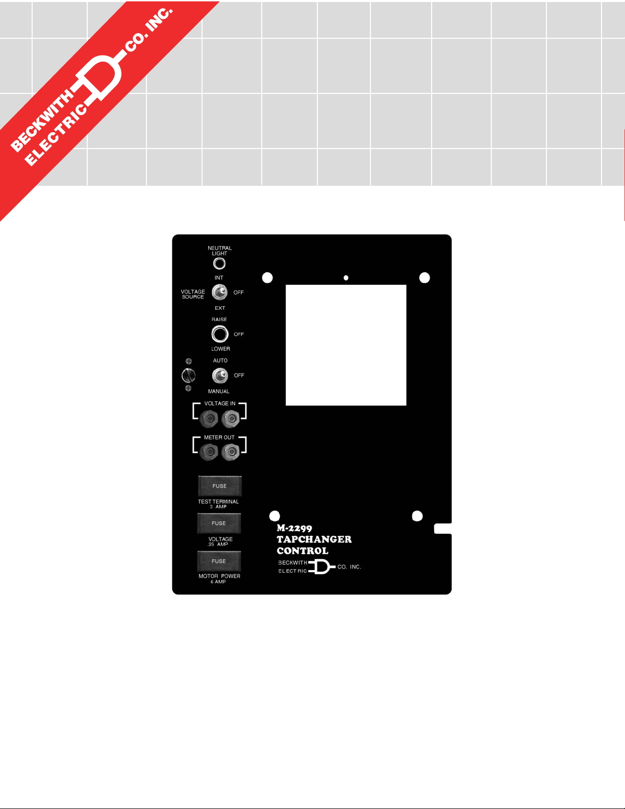
Separate fuses for test terminal, voltage sensing and motor power are on the front panel. Spare fuses for
each are in the fuse holder.
Binding posts on the front panel allow easy connections for test procedures.
RAISE/OFF/LOWER, AUTO/OFF/MANUAL, and VOLTAGE SOURCE switches and NEUTRAL LIGHT
are standard.
NEUTRAL LIGHT will light to indicate that the regulator is in the neutral position, for those regulators
equipped with a circuit for this purpose.
Testing Specifications
High Voltage: All input and output terminals will withstand 1500 V ac rms to chassis or instrument ground
for one minute with a leakage current not to exceed 25 mA, for all terminals to ground. Input and output
circuits are electrically isolated from each other, from other circuits and from ground.
Surge Withstand Capability: All input and output circuits are protected against system transients. Units
pass all requirements of ANSI/IEEE C.37.90.1-1989 defining surge withstand capability.
Radiated Electromagnetic Withstand Capability: All units are protected against electromagnetic radiated interference from portable communications transceivers.
Environmental
Temperature Range: Functionality is maintained from –40° to +85° C.
Humidity: Functionality is maintained under 95% relative humidity (non-condensing).
Fungus Resistance: A conformal printed circuit board coating inhibits fungus growth.
Physical
Size with M-2001 Series Digital Tapchanger Control: 12" high x 9-1/4" wide x 4-1/8" deep
(30.48 cm x 23.5 cm x 10.48 cm)
Approximate Weight: 2 lbs (0.9 kg)
Approximate Shipping Weight: 5 lbs, 7 oz (2.47 kg)
Approximate Weight with M-2001 Series Digital Tapchanger Control: 6 lbs, 2 oz (3.23 kg)
Approximate Shipping Weight with M-2001 Series Digital Tapchanger Control: 11 lbs, 2 oz (5.1 kg)
Warranty
The M-2299 Adapter Panel is covered by a five year warranty from date of shipment.
Specification subject to change without notice.
0
0
0
2
:
d
1
e
r
0
e
0
t
s
9
i
g
e
O
R
S
I
6190 - 118th Avenue North • Largo, Florida 33773-3724 U.S.A.
Printed in U.S.A. (10.24.02)
BECKWITH ELECTRIC CO., INC.
PHONE (727) 544-2326 • FAX (727) 546-0121
E-MAIL marketing@beckwithelectric.com
WEB PAGE www.beckwithelectric.com
800-2299-SP-00MC4 01/07© 2000 Beckwith Electric
Page 4
WARNING
DANGEROUS VOLTAGES, capable of causing death or serious
injury, are present on the external terminals and inside the equipment. Use extreme caution and follow all safety rules when handling, testing or adjusting the equipment. However, these internal
voltage levels are no greater than the voltages applied to the external terminals.
DANGER! HIGH VOLTAGE
– This sign warns that the area is connected to a dangerous high voltage, and you
must never touch it.
PERSONNEL SAFETY PRECAUTIONS
The following general rules and other specific warnings throughout the manual must be followed during application,
test or repair of this equipment. Failure to do so will violate standards for safety in the design, manufacture, and intended
use of the product. Qualified personnel should be the only ones who operate and maintain this equipment. Beckwith
Electric Co., Inc. assumes no liability for the customer’s failure to comply with these requirements.
– This sign means that you should refer to the corresponding section of the operation
manual for important information before proceeding.
Always Ground the Equipment
To avoid possible shock hazard, the chassis must be connected to an electrical ground. When servicing
equipment in a test area, the Protective Earth Terminal must be attached to a separate ground securely
by use of a tool, since it is not grounded by external connectors.
Do NOT operate in an explosive environment
Do not operate this equipment in the presence of flammable or explosive gases or fumes. To do so would
risk a possible fire or explosion.
Keep away from live circuits
Operating personnel must not remove the cover or expose the printed circuit board while power is applied. In no case may components be replaced with power applied. In some instances, dangerous voltages may exist even when power is disconnected. To avoid electrical shock, always disconnect power and
discharge circuits before working on the unit.
Exercise care during installation, operation, & maintenance procedures
The equipment described in this manual contains voltages high enough to cause serious injury or death.
Only qualified personnel should install, operate, test, and maintain this equipment. Be sure that all personnel safety procedures are carefully followed. Exercise due care when operating or servicing alone.
Do not modify equipment
Do not perform any unauthorized modifications on this instrument. Return of the unit to a Beckwith
Electric repair facility is preferred. If authorized modifications are to be attempted, be sure to follow
replacement procedures carefully to assure that safety features are maintained.
Page 5

PRODUCT CAUTIONS
Before attempting any test, calibration, or maintenance procedure, personnel must be completely familiar
with the particular circuitry of this unit, and have an adequate understanding of field effect devices. If a
component is found to be defective, always follow replacement procedures carefully to that assure safety
features are maintained. Always replace components with those of equal or better quality as shown in the
Parts List of the Instruction Book.
Avoid static charge
This unit contains MOS circuitry, which can be damaged by improper test or rework procedures. Care
should be taken to avoid static charge on work surfaces and service personnel.
Use caution when measuring resistances
Any attempt to measure resistances between points on the printed circuit board, unless otherwise noted
in the Instruction Book, is likely to cause damage to the unit.
Page 6

TABLE OF CONTENTS
M-2299 Adapter Panel
Application Guide
1.0 Description ................................................................................................................... 1
Standard Features ....................................................................................................... 1
2.0 Installation .................................................................................................................... 2
2.1 Removal of the Toshiba Regulator ............................................................................. 2
Figure 1 Toshiba Regulator in Cabinet .....................................................................
2.2 Installation of the M-2001 Series Digital Tapchanger Control ................................... 3
2.3 Installation of the M-2299 ........................................................................................... 3
Figure 2 M-2299 Adapter Panel and M-2001 Tapchanger Control in Cabinet ........
Figure 3 Mounting Dimensions .................................................................................
Figure 4 Wiring Harness and External Connections ................................................
2.4 Lightning Protection ..................................................................................................... 6
2
3
4
5
3.0 External Connections ................................................................................................... 6
Figure 5 M-2001 and M-2299 Typical Connections .................................................
3.1 Features ....................................................................................................................... 8
Neutral Light Circuit ..................................................................................................... 8
Auto Disable Input ....................................................................................................... 8
Local/Remote Input...................................................................................................... 8
Multi-Step Voltage Reduction ...................................................................................... 8
Operations Counter Input ............................................................................................ 8
Table 1 Multi-step Voltage Reduction External Connections ..................................
3.2 Typical Connections for Toshiba Regulators.............................................................. 9
Figure 6 Tapchanger Control and LTC Backup Control Interconnections ...............
3.3 Use of the M-0329 LTC Backup Control with the Tapchanger Control..................... 9
4.0 M-2001 Tapchanger Control Software Settings ........................................................ 10
4.1 M-0329 LTC Backup Control Settings ...................................................................... 10
7
8
9
Page 7

5.0 Test Procedures ........................................................................................................ 10
Equipment Required .................................................................................................. 10
Setup Procedure ........................................................................................................ 10
Table 2 Initial Settings ............................................................................................
10
5.1 Bench Test................................................................................................................. 11
Resistance ................................................................................................................. 11
Voltage Source Switch .............................................................................................. 11
Counter/Neutral Light/Tap Position ........................................................................... 11
Block Raise/Block Lower/Dead Band ....................................................................... 11
Figure 7 M-2299 Test Procedure External Connection..........................................
12
5.2 M-2001 Checkout Procedure ..................................................................................... 13
Basic Operational Test .............................................................................................. 13
5.3 In-Service Test .......................................................................................................... 13
6.0 Checkout Procedure .................................................................................................. 13
6.1 Power .......................................................................................................................... 13
Figure 8 Setup for Current Checkout Procedure....................................................
14
6.2 Voltage Source Switch .............................................................................................. 15
7.0 Maintenance ............................................................................................................... 15
Printed in U.S.A. (
800-2299-AG-00MC4 01/07© 2000 Beckwith Electric Co.
(#02-88)(12.18.00)
Page 8

M-2299 Application Guide
The Beckwith Electric M-2299 Adapter Panel, used
in conjunction with the M-2001 Series Digital
Tapchanger Control, uses modern electronic digital
design and digital processing circuitry to achieve
an overall stability and resolution unattainable with
electromechanical and analog design tapchanger
controls. CMOS semiconductors are used throughout
the design.
NOTE: The hinge pins
must be saved
from the
original control. The BT terminal blocks remain in
the control cabinet.
1.0 Description
Standard Features
The M-2299 Adapter Panel, with the M-2001 Series
Digital Tapchanger Control, provides a solid-state
voltage control relay designed to directly replace
the Toshiba TB-R800 control. The combination of
the Tapchanger Control and Adapter Panel includes
the following features:
1. Voltage waveform sampling and digital
processing circuitry ensure accurate rms
voltage sensing in the presence of
distortion on the input voltage and
current.
2. Accuracy exceeds the ANSI/IEEE
C57.15-1986 Class 1 specification over
the temperature range of –40° C to
+70° C.
4. Separate motor power, test terminal and
voltage sensing fuses are easily
changed from the front panel and spare
fuses are provided in their respective
fuseholders.
5. Easily tested by use of the following:
a. VOLTAGE SOURCE switch
disconnects the voltage transformer
input and connects the VOLTAGE
IN binding posts to the voltage input
and motor circuit.
b. VOLTAGE IN binding posts on the
front panel allow application of a
120 V rms nominal voltage to the
unit for test procedures.
c. METER OUT binding posts on the
front panel allow reading of the input
voltage when used in conjunction
with the BIAS TEST VOLTAGE
screen of the M-2001 Series Digital
Tapchanger Control.
d. RAISE and LOWER band edge LEDs
on the M-2001 Tapchanger Control
indicate when the input voltage is
outside the voltage band.
6. NEUTRAL light illuminates when the
regulator is in the neutral tap position.
7. AUTO/OFF/MANUAL switch allows
manual operation of the control.
3. Input and output circuits are protected
against system transients. Units pass
all requirements of ANSI/IEEE C37.90.11989, which defines surge withstand
capability. All input and output terminals
will withstand 1500 V ac rms to chassis
or instrument ground for one minute with
a leakage current not to exceed 25 mA,
from all terminals to ground. Input and
output circuits are electrically isolated
from each other, from other circuits and
from ground.
–1–
Page 9

M-2299 Application Guide
2.0 Installation
The M-2299 has hinges on the right side that allow
easy mounting into the existing Toshiba regulator
cabinet. Refer to Figure 1, below.
2.1 Removal of the Toshiba
Regulator
Refer to Figure 1, and Figure 3, Outline Dimensions.
1. Open the cabinet door of the Toshiba
regulator.
2. Loosen the two thumbscrews on the
control panel and swing the panel
outward.
3. Disconnect the three plugs that connect
the wiring harness to the rear of the
Toshiba control panel.
4. Remove and save the two hinge pins
and lift the Toshiba control panel off of
the hinges.
NOTE: The two hinge pins
must be saved
the original control.
5. Remove all control side wiring harness
connections from the BT1 terminal block.
6. Remove all wiring connections from the
capacitor.
7. Remove the “AUTO/MANUAL, RAISE/
LOWER switch” bracket from the cabinet
by removing the two screws (save
screws).
8. Remove the panel for the “Operations
Counter, Fuse Holder and Test Jack
Fixture” (save screws).
from
b
TOSHIBA
TB-R800
478593
Figure 1 Toshiba Regulator in Cabinet
d
g
–2–
Page 10

M-2299 Application Guide
2.2 Installation of the M-2001
Series Digital Tapchanger
Control
Mount the M-2001 Tapchanger Control to the back
of the M-2299 Adapter Panel and secure with the
four screws provided. The four screws are shipped
in a drawstring bag which is attached to the adapter
panel.
2.3 Installation of the M-2299
Refer to Figure 2, below.
1. Mount the supplied printed circuit board
against the rear of the cabinet in the
screw holes from the "AUTO/MANUAL,
RAISE/LOWER switch" bracket, utilizing
saved screws. See Figure 4, Wiring
Harness and External Connections.
2. Connect the supplied printed circuit board
TB1 wiring harness to the BT1 terminal
block and capacitor. Refer to Figure 4
for wiring connections.
3. Mount the M-2299 Adapter Panel (with
the M-2001) onto the hinges in the control
cabinet and install the two hinge pins
saved from the original regulator. Leave
the panel swung outward so that the
back of the panel is accessible.
4. Connect the M-2299 and M-2001B wiring
connectors to the supplied circuit board
and Neutral Light. Refer to Figure 4 for
wiring connections.
5. Swing the adapter panel closed and turn
knob to latch securely.
NEUTRAL
LIGHT
INT
VOLTAGE
SOURCE
EXT
RAISE
LOWER
AUTO
MANUAL
VOLTAGE IN
METER OUT
TEST TERMINAL
3 AMP
VOLTAGE
.25 AMP
MOTOR POWER
6 AMP
OFF
OFF
OFF
U
UP
E
ENTER
D
DOWN
-M
0120
M-2299
TAPCHANGER CONTROL
BECKWITH
ELECTRIC
CO. INC
A
REIS
L
EWR
ROE
R
VPW
OK
COM 2
B
.
Figure 2 M-2299 Adapter Panel and M-2001 Tapchanger Control in Cabinet
–3–
Page 11

M-2299 Application Guide
VOLTAGE
SOURCE
NEUTRAL
LIGHT
INT
EXT
RAISE
9.17
[23.29]
OFF
12.00
[30.48]
LOWER
AUTO
MANUAL
VOLTAGE IN
METER OUT
FUSE
TEST TERMINAL
3 AMP
FUSE
VOLTAGE
.25 AMP
FUSE
MOTOR POWER
6 AMP
OFF
U
OFF
UP
D
DOWN
E
ENTER
-M
0120
M-2299
TAPCHANGER CONTROL
BECKWITH
ELECTRIC
CO. INC
B
A
REIS
O
L
EWR
R
E
R
VPW
OK
COM 2
.
NOTE: Values in brackets are in centimeters.
Figure 3 Mounting Dimensions
–4–
Page 12

BT1
TB1-8
C1-2
TB1-15
C1-1
TB1-13
M-2299 Application Guide
REV. A
ELECTRIC
CO. INC.
BE# 450-00200
BECKWITH
P-1778
J7
16 21
22 27
TB2
1
J5 J4
C1
+
R3
R1
1516
2324
14
13 12 11 10 9
171819202122
C7 C8
U2
C6
TB1-8
TB1-3
TB1-4
TB1-1
TB1-11
TB1-9
TB1-10
TB1-14
+
R2
RV5
78
RV1
R4
R5
+
RV4
P1
C4
F1
JP1
23456
C3
C12
1
C11
R15
R12
RV6
R11
R14
R13
R6
U3
R9
R10
R7
J1
R8
TB1
J6
1
1
BT1-6
BT1-8
BT1-7
C1-2
RV2
RV3
C2
U1
D1
D2
D3
C5
C9
15
C10
C1-1
BT1-9
BT1-1
BT1-11
BT1-10
BT1-5
BT1-4
BT1-12
BT1-1
C1-2
C1-1
J7
J6
J5
J4
Terminal Block
Connections
TB-1
Circuit Board
Capacitor
BT1
M-2001
C1-2
C1-1
To Tapchanger
REV. A
CO. INC.
BE# 450-00200
P-1778
16 21
22 27
TB2
1
J5 J4
C1
+
R3
RV5
R1
1516
2324
78
14
RV1
13 12 11 10 9
RV4
P1
JP1
23456
C3
171819202122
1
C11
RV6
C7 C8
R14
U2
U3
C6
+
R7
J1
R8
ELECTRIC
BECKWITH
J7
R2
R4
R5
+
C4
F1
C12
R15
R12
R11
R13
R6
R9
R10
Customer
Terminal Block
TB1
J6
1
1
RV2
RV3
C2
U1
D1
D2
D3
C5
C9
15
C10
1
2
6
5
4
6
5
4
6
5
4
R
R
1
1 2
1
D1
1
2
3
S4
1
2
3
S2
1
2
3
S3
BP1
B
B
BP2
2
F2
F3
2
F4
Figure 4 M-2299 Wiring Harness and External Connections
–5–
Page 13

M-2299 Application Guide
2.4 Lightning Protection
It has been determined that transient voltages in
excess of 1500 V ac rms can exist on the “ground”
lead normally tied to TB1-8 on the printed circuit
board. In the Tapchanger Controls, these voltages
are suppressed by varistors which still permit the
unit to pass a 1500 V ac Hi Pot test for one minute
with a leakage current of approximately 15 mA, all
terminals to ground.
▲ CAUTION: For proper protection against system
surges, chassis ground must be connected to earth
ground.
Multiple VT grounds far apart must be avoided
since a varying difference in ground voltage could
add or subtract from the effective voltage and
cause variation in the Tapchanger Control’s
bandcenter voltage setpoint.
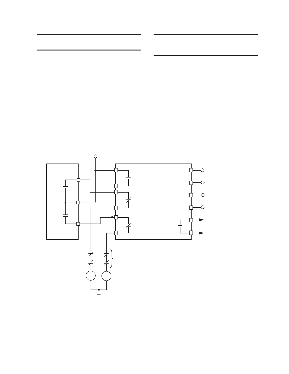
3.0 External Connections
Power and voltage sensing are obtained either from
a common source or from independent sources
having a nominal 120 V ac output. Normally, this is
line-to-neutral voltage, although line-to-line voltage
can also be used if recognition is made of any
phase shift between the voltage and current signals
when using line drop compensation.
Load current must be reduced by an appropriate
auxiliary current transformer to 0.2 A “full scale”
before connecting to the M-2299 current inputs.
The Beckwith Electric M-0121 (5.0 A to 0.2 A) or
M-0169 (5.0 A or 8.66 A to 0.2 A) Auxiliary Current
Transformer can be used for this purpose. The
M-0121 can be used with Beckwith Electric
Tapchanger Controls when the only burden present
is the Line Drop Compensator circuit of the voltage
regulating relay. The M-0169 is used in high burden
circuits, such as are found in paralleling schemes.
Outputs of the auxiliary CTs are protected against
overvoltage. For further information, obtain Beckwith
Electric Application Note #17, “Basic Considerations
for the Application of LTC Transformers and
Associated Controls.”
The external connections for the M-2299 are made
to terminal blocks TB1 and TB2 on the printed
circuit board. The wiring harness and external
connections for the M-2299 are shown in Figure 4,
Wiring Harness and External Connections, and
Figure 5, M-2001 and M-2299 Typical Connections.
–6–
Page 14

M-2001
TAPCHANGER
CONTROL
FUNCTIONS
OP
COUNTER
NEUTRAL
NC
See Note
NO
+12 V dc
MANUAL RAISE
MANUAL LOWER
MANUAL
OFF
AUTO
TO
CONTROL
METER OUT
M-2299
ADAPTER PANEL
FUNCTIONS
OFF (MOM)
INT
OFF
EXT
INT
OFF
EXT
VOLTAGE IN
TEST
TERMINAL
FUSE 3A
FRONT PANEL INPUTS
MOTOR POWER
FUSE (6 A)
VOLTAGE IN
FUSE (1/4 A)
NEUTRAL
LIGHT
TB1
TB1
10
11
12
13
14
15
TB2
16
17
18
19
20
21
22
23
24
25
26
27
M-2299 Application Guide
6
1
2
3
4
5
6
7
8
9
VOLTAGE REDUCTION STEP #2 CONTACT
8
7
2
3
VOLTAGE REDUCTION
STEP #1 CONTACT
1
11
MOTOR POWER
10
NEUTRAL LIGHT SWITCH
5
N/U
4
12
LINE
CURRENT
1
SHORTING SWITCH
LOCAL/REMOTE
AUTO DISABLE
MANUAL RAISE
MANUAL LOWER
N/U
SELF-TEST ALARM (RETURN)
SELF-TEST ALARM (POLARITY)
USER-PROGRAMMABLE ALARM (RETURN)
USER-PROGRAMMABLE ALARM (POLARITY)
+12 V dc WETTING SUPPLY
POLARITY CONTACT
RESISTOR NETWORK WIPER
POSITION RESISTOR
9
20, 21 or 22
on T.C.
OPERATIONS COUNTER
SWITCH
CT
MOTOR
LR
NEUTRAL
VOLTAGE IN
(REGULATED
120 V)
CT
Toshiba Terminals
M-2299 Terminals
NOTE: The self-test alarm and user-programmable alarm contacts are shown in the de-energized state (no
voltage applied). The self-test alarm contacts open after the M-2001 passes the self-test; the user-programmable alarm contacts close when an alarm is recognized.
8 WARNING: In no case should the line current circuit be interrupted with the regulator or transformer
energized.
Do not remove auxiliary current transformers without shorting the current inputs. Death or severe
electrical shock can occur.
Figure 5 M-2001 and M-2299 Typical Connections
–7–
Page 15

M-2299 Application Guide
3.1 Features
Neutral Light Circuit
The M-2299 is prepared for use with regulators
which use a neutral light. Toshiba products require
that the Neutral Light terminal TB1-11 (BT-5) be
grounded when the light is to be illuminated.
Auto Disable Input
To disable automatic operation of the M-2299,
remove the jumper between TB2-18 and TB2-19 on
the printed circuit board. If SCADA is used to
enable and disable this function, a contact rated at
6 A minimum can be connected between the
terminals.
Local/Remote Input
Removing the jumper between TB2-16 and TB2-17
prohibits operation by disabling the M-2001
Tapchanger Control’s automatic raise and lower
outputs and also by disabling the M-2299 Adapter
Panel’s manual RAISE/OFF/LOWER toggle switch.
Removing this jumper does
supplied motor voltage input to the manual raise/
manual lower contacts on the adapter panel.
not
disable the SCADA-
Multi-Step Voltage Reduction
On the M-2299, TB1-2 and TB1-7 on the printed
circuit board are used together to provide up to
three levels of voltage reduction. The external
connections to achieve these steps are shown in
Table 1, below, and Figure 5, M-2001 and M-2299
Typical Connections. (Voltage reduction amounts
are set within the M-2001 Tapchanger Control
software.)
▲ CAUTION: Voltage applied through dry contacts
to actuate Voltage Reduction Steps 1, 2, and 3
must
be +12 V dc obtained from pin TB2-27 of the M-2299
adapter panel.
Operations Counter Input
An operations count is registered by momentarily
grounding TB1-13 through an external dry contact
from the load tapchanger. The input is level-sensitive.
Make sure that any “wetting” voltages are removed
from the counter contacts before installing the
M-2299 Adapter Panel/M-2001 Tapchanger Control.
▲ CAUTION: Do not apply either +12 V dc or 120 V
ac to this terminal.
:tniopteSnoitcudeRegatloV
egnaRreilpitluM
:1#tniopteSnoitcudeRegatloV
1ot0
tloV
1ot0
1ot0
:2#tniopteSnoitcudeRega
:3#tniopteSnoitcudeRegatloV
7-1BT
2-1BT
morf"egatloVgnitteW"ylppA
#lanimreTot72-2BT
2-1BTdna7-1BT
Table 1 Multi-Step Voltage Reduction External Connections
–8–
Page 16
M-2299 Application Guide
3.2 Typical Connections for
Toshiba Regulators
In general, the tapchanger motor must be operated
from a different transformer than the VT used to
measure regulated voltage. If this is not done,
hunting at the upper band edge may result. As soon
as the motor starts and before it is sealed in, the
motor current can drop the voltage within the band
and reset the control. Some motor seal-in schemes
are fast enough to prevent this, but others are not.
A typical connection for an M-2299 is shown in
Figure 5, M-2001 and M-2299 Typical Connections.
Connections are simplified and may not show all
functions required in a typical load tapchanging
transformer control scheme; for example, seal-in
contacts, limit switches, etc.
MOTOR
TAPCHANGER
CONTROL
R
SUPPLY
TB1-7
TB1-8
TB1-11
*
TB1-12
*
TB1-6
TB1-7
LOWER
BLK
RAISE
3.3 Use of the M-0329 LTC
Backup Control with the
Tapchanger Control
The M-0329 is a single-phase, solid-state backup
control that prevents a defective tapchanger control
from running the voltage outside the upper and
lower voltage limits. The Block Raise and Block
Lower voltage levels are set by accurately calibrated
dials.
The M-0329 LTC Backup Control is connected as a
two terminal device to the voltage transformer.
Figure 6, below, shows the typical interconnection
of the two devices with motor auxiliary relays.
The M-0329 Instruction Book is available on request
and gives added details. Please refer to the M-0329
Instruction Book for complete ordering information.
M-0329
90 BACKUP
1
120 VAC POWER
2
3
REGULATED VOLTAGE
4
84R
TB1-9
TB1-10
84L
14
BLK
LOWER
LIMIT SWITCHER, AUXILIARY CONTACTS AS
REQUIRED IN MOTOR CONTROL CIRCUITS
84R - RAISE MOTOR AUXILIARY RELAY
84L - LOWER MOTOR AUXILIARY RELAY
15
L
TB1-9
*
NOTE: If first customer protection is not required, delete these connections.
Figure 6 Tapchanger Control and LTC Backup Control Interconnections
ALARM
–9–
Page 17

M-2299 Application Guide
4.0 M-2001 Tapchanger Control
Software Settings
Adjust the BANDCENTER setting to the nominal
voltage desired. Adjust the BANDWIDTH setting to
the desired voltage band, centered on the
Bandcenter setpoint, that the voltage must exceed
before timer and subsequent tapchanger operation
occurs. Adjust the TIME DELAY setpoint to a
sufficient amount to eliminate excessive tapchanger
operations. The LINE DROP COMPENSATOR
should be set for the line impedance from the
transformer to the load center. For further information,
obtain Beckwith Electric Application Note #17,
“
Basic Considerations for the Application of LTC
Transformers and Associated Controls
.”
4.1 M-0329 LTC Backup Control
Settings
The BANDCENTER and BANDWIDTH dials on the
M-0329 LTC Backup Control should be set so that
the Block Lower limit is a small amount
(approximately 2 V) below the lower band limit of
the Tapchanger Control, and the Block Raise limit
is a similar amount above the upper limit if line drop
compensation is not used.
If line drop compensation is used, the M-0329
Block Raise limit should be set at the maximum
voltage desired at the transformer secondary under
full load.
The M-0329 LTC Backup Control also includes a
deadband or runback function that regulates the
maximum voltage from the transformer. This “Lower”
function operates slightly above the Block Raise
limit and is connected to force the tapchanger to
lower the voltage if the upper limit is exceeded.
5.0 Test Procedures
Equipment Required
• 0–200 mA current supply with phase angle
settings of 0° to +90°
• 90–145 V ac voltage source at 60 Hz
• High impedance true RMS voltmeter with
accuracy on ac of at least ±0.2% of
reading
• Accurate Stop watch
Set-up Procedure
1. Make electrical connections as shown
in Figure 7, Test Procedure External
Connection.
NOTE: There is a one second delay between
out-of-band condition and panel LED indication.
2. Initial settings
sgnitteSlaitinI
retnecdnaBV0.021
htdiwdnaBV0.2
ecnatsiseRCDLV0.0
ecnatcaeRCDLV0.0
gnilellaraPdohteMtnerruCgnitalucriC
BV0.531
esiaRkcol
rewoLkcolBV0.501
dnabdaeDV0.2
remiTsdnoces0.5
–10–
Table 2 Initial Settings
Page 18

M-2299 Application Guide
5.1 Bench Test
NOTE: This test assumes that the M-2001
Tapchanger Control is connected to the M-2299
Adapter Panel.
1. Apply 120.0 V ac from power source.
2. The display of the M-2001 will
automatically advance to Local Voltage
screen.
3. Increase voltage to 121.2; LOWER LED
should light.
4. Decrease voltage to 118.8; RAISE LED
should light.
5. Set input voltage to 120.0 V ac. Wait
for RAISE and LOWER LEDs to
extinguish.
6. Increase voltage to 122.0 V ac.
7. Start timing when voltage passes
121.0 V.
8. Stop timing when lamp connected to
LOWER output lights (should be 5
seconds).
Resistance
1. Apply 100.0 mA in-phase current to
TB1-14 (load current-polarity) and
TB1-15 (load current-return) of the
adapter panel. (Set S
IR.)
2. Set LDC Resistance to 24.0 V; RAISE
LED should light.
3. Increase input voltage to 132.0 V ac;
RAISE and LOWER LEDs should be
extinguished.
4. Set LDC Resistance to –24.0 V; LOWER
LED should light.
5. Decrease input voltage to 108.0 V ac;
both RAISE and LOWER LEDs should
extinguish.
6. Set LDC Resistance to 0.0 V.
to LDC and S2 to
1
Voltage Source Switch
1. Set AUTO/OFF/MANUAL switch to OFF.
2. Set VOLTAGE SOURCE switch to EXT.
3. Verify no manual Raise or Lower output.
4. Attach voltmeter to Meter Out terminals.
5. Verify no voltage is present.
6. Apply 120 V ac to the Voltage In jack
(Black-Neutral, Red-Hot).
7. Set AUTO/OFF/MANUAL switch to
AUTO.
8. Verify normal raise and lower operation.
9. Return the VOLTAGE SOURCE switch
to INT.
Counter/Neutral Light
1. Set the M-2001 Tapchanger Control to
display the Operations Count screen.
2. Verify counter operation by connecting
a switch between TB1-13 (operations
counter input) and TB1-8 (neutral) of the
adapter panel.
3. Jumper TB1-11 (neutral light) to TB1-8
(neutral).
4. The neutral light on the adapter panel
should light.
5. Remove the jumper.
Block Raise/Block Lower/Dead Band
1. Set Block Raise to 126.0 V.
2. Set Block Lower to 114.0 V.
3. Set the M-2001 Tapchanger Control to
display the Bias Voltage screen.
4. Press ENTER.
5. Increase voltage to 126.5 V; BR should
appear on the screen.
6. Increase voltage to 128.5 V; BR goes
off and FL appears on the screen.
7. Decrease voltage to 113.5 V; BL appears
on the screen.
–11–
—Bench Test Complete—
Page 19

M-2299 Application Guide
Supply
120 V Fixed
H
I
I
R1
H
Input
Variac
Supply
Adjustable
80 to 140 V ac
N
S2
R
L
I
C1
H
N
Discrete Elements or Doble F2200
Normally open
pushbutton test switch
for Functional Indicator
120 V Lamp or Relay Coil
Polarity Contact
1
TB1
(approx. 1200 ý, 15 W or greater)
S1
LDC
OFF
Resistor Network Wiper
Voltage Reduction Step #2 Input
2
Position Resistor
3
4
Tapchanger Raise Output
Tapchanger Lower Output
Voltage Reduction Step #1 Input
5
6
7
(approx. 2.2 µF, 600 V ac Mylar Film)
Neutral
Motor Power
Regulated Voltage
8
9
Neutral Light
11
10
Operations Counter Input
Load Current (Polarity)
N/U
12
Load Current (Return)
13
14
15
Contact Wetting Supply (+12 V dc)
27
TB2
Local/Remote
16
17
Jumpers in place for motor power continuity.
Auto Disable
18
19
Load
I
Position
Tap
Figure 7 M-2299 Test Procedure External Connection
–12–
Page 20

M-2299 Application Guide
5.2 M-2001 Checkout Procedure
NOTE: This test of the M-2001 assumes that the
unit remains connected to the adapter panel.
Basic Operational Test
1. Apply 120.0 V ac to TB1-9 (motor power)
and TB1-10 regulated voltage) of adapter
panel.
2. Connect neutral to TB1-8 (neutral).
3. Verify local voltage y input voltage
±0.3 V.
4. Apply 100.0 mA in-phase current to
TB1-14 (load current-polarity) and
TB1-15 (load current-return) of the
adapter panel. Verify Control Load I y
100 mA and Power Factor y 1.0 ±0.02.
5. Verify UP, DOWN and ENTER buttons
work.
—Checkout Procedure Complete—
5.3 In-Service Test
1. Set the M-2001 Tapchanger Control to
display Bias Voltage screen.
2. Press ENTER.
3. Use UP and DOWN buttons to cause
RAISE and LOWER outputs.
—In-Service Test Complete—
6.0 Checkout Procedure
NOTE: All Beckwith Electric units are fully cali-
brated at the factory. There is no need to re-calibrate
the units before initial installation.
Set the AUTO/OFF/MANUAL switch to OFF.
Inspect the MOTOR POWER and VOLTAGE fuses
to ensure they are correctly sized and have not
blown.
6.1 Power
1. Remove any external connection
between TB1-9 and TB1-10 which are
located on the adapter panel printed
circuit board. Also remove any voltage
applied to TB1-9 externally. Using a
voltmeter, make sure that the voltage
applied to TB1-10 is nominal 120 V ac
with respect to TB1-8 (neutral). Apply
power to TB1-10 (hot) and TB1-8
(neutral).
8 WARNING: Voltage applied at the
test terminal may energize the regulator or transformer to a high voltage through the voltage
transformer.
Death or severe electrical shock can occur.
Do not connect any voltage source at the
OUT
test terminal.
2. Connect a voltmeter to the METER OUT
test terminal on the front of the adapter
panel. 120 V ac should be indicated.
METER OUT
METER
Return unit to desired settings
▲ CAUTION: Do not reverse the ground and hot
wires when connecting an external source. A 3 AG
fuse (F2) is installed to protect the relay from damage if these connections are accidentally reversed.
Spare fuses are supplied inside the fuse holders.
Units returned with only a blown fuse are not covered by warranty, and a nominal repair charge will be
made for replacement of the fuse. Please check the
fuse before returning the unit for repair, in order to
avoid unnecessary repair charges.
–13–
Page 21

M-2299 Application Guide
3. Apply motor power to TB1-9 (hot) and
TB1-8 (neutral). Set the AUTO/OFF/
MANUAL switch to MANUAL and using
the RAISE/OFF/LOWER switch, verify
that the motor runs in the proper direction
when this switch is in the RAISE and
LOWER positions.
4. Set the AUTO/OFF/MANUAL switch to
the AUTO position. Refer to the Field
Checkout Procedure as found in the
Status & Setpoint Review Guide of the
M-2001 Tapchanger Control Instruction
Book for test/operation procedures.
5. As shown in Figure 6-1, Typical External
Connections, in the M-2001B Instruction
Book, temporarily place a shorting device
across the LDC-CT secondary to short
the line drop compensator circuit, and
place another shorting device across
TB1-3 and TB1-4 to short the circulating
current paralleling input, for the load
current check. Insert an ammeter
between the polarity input and TB1-14.
Open the load current shorting device
and with a known load on the transformer
or regulator, measure the current in the
load current circuit to ensure that this
current is correct for 0.2 A full load.
6. Replace the shorting device across the
load current input and remove the
ammeter. Reconnect polarity to the unit
and remove both jumpers. The LINE
DROP COMPENSATOR will be
activated. Correct CT polarity can be
checked by simply incorporating
sufficient +R compensation. The
regulator should time out and run so as
to raise the output voltage.
8 WARNING: In no case should the load current
circuit be interrupted with the regulator or transformer energized.
Do not remove auxiliary current transformers
without shorting the current inputs.
Death or severe electrical shock can occur.
M-2299
TAPCHANGER
CONTROL
TB1 on printed circuit board
N/U
3
N/U
4
14
A
200 mA
15
LOAD CURRENT
AUX
CT
5 A
Figure 8 Setup for Current Checkout Procedure
Normally 1-CT on
X , X , X bushing
123
Shorting
device
LDC-CT
XXXX:5 A
–14–
Page 22

M-2299 Application Guide
6.2 Voltage Source Switch
The VOLTAGE SOURCE switch will disconnect all
power from the unit when in the EXT position with
no source connected to the front panel voltage and
motor power inputs.
▲ CAUTION: Do not reverse the ground and hot
wires when connecting an external source. A 3 AG
(F2) is installed to protect the relay from damage if
these connections are accidentally reversed.
With the VOLTAGE SOURCE switch in the EXT
position, the sensing and motor power circuits are
connected to the VOLTAGE IN binding post on the
front panel. The unit can be tested using an external
120 V rms source of proper polarity applied to these
terminals. Testing can be accomplished by adjusting
the amplitude of the external source.
7.0 Maintenance
Due to the nature of the circuitry in the M-2001
Tapchanger Control, field repair is not
recommended. All units are fully calibrated at the
factory prior to shipment; there is no need to recalibrate a unit prior to initial installation. In the
event that a unit does not operate properly, it
should be established that the problem is caused
by a malfunction of the Tapchanger Control and not
caused by an external fault or wiring error. Check
for blown fuses on the Adapter Panel. If the
Tapchanger Control is still not operating properly,
set the AUTO/OFF/MANUAL switch on the Adapter
Panel to MANUAL. Once this is accomplished, the
Tapchanger Control can be disconnected and
returned to Beckwith Electric. Pack the unit carefully
(in the original carton if possible), assuring that
there is adequate packing material to protect the
contents.
NOTE: Any equipment returned for repair must be
sent with transportation charges prepaid. The equipment must remain the property of the user. The warranty is void if the value of the unit is invoiced to
Beckwith Electric at the time of return or if the unit
is returned with transportation charges collect.
If under warranty, units will be repaired rapidly and
returned at no cost and with return transportation
paid if the fault is found to be due to workmanship
or failure of material. If a unit is under warranty and
express shipment for return of the repaired unit is
requested, shipping charges will be billed at the
current rate. If the fault is due to abuse or misuse,
or if the unit is out of warranty, a modest charge will
be made. Repair can normally be expected to take
two weeks, plus shipping time. If faster service is
required, it should be requested at the time of
return.
NOTE: Adapter panels returned with only a blown
fuse are not covered by warranty and a nominal repair charge will be made for replacement of the fuse.
Please check the fuses before returning the adapter
panel for repair in order to avoid unnecessary repair
charges.
To help in analyzing the problem, a complete
description of the malfunction and conditions leading
to the failure should be included with the unit.
–15–
Page 23

M-2299 Application Guide
This Page Left Intentionally Blank
–16–
Page 24

Legal Information
Patent
The units described in this manual are covered by
U.S. Patents, with other patents pending.
Buyer shall hold harmless and indemnify the Seller,
its directors, officers, agents, and employees from
any and all costs and expense, damage or loss,
resulting from any alleged infringementof United
States Letters Patent or rights accruing thereform or
trademarks, whether federal, state, or common law,
arising from the Seller’s compliance with Buyer’s
designs, specifications, or instructions.
Warranty
Seller hereby warrants that the goods which are the
subject matter of this contract will be manufactured
in a good workmanlike manner and all materials
used herein will be new and reasonably suitable for
the equipment. Seller warrants that if, during a
period of five years from date of shipment of the
equipment, the equipment rendered shall be found
by the Buyer to be faulty or shall fail to peform in
accordance with Seller’s specifications of the
product, Seller shall at his expense correct the
same, provided, however, that Buyers shall ship the
equipment prepaid to Seller’s facility. The Seller’s
responsibility hereunder shall be limited to replacement value of the equipment furnished under this
contract.
Seller makes no warranties expressed or implied
other than those set out above. Seller specifically
excludes the implied warranties of merchantibility
and fitness for a particular purpose. There are no
warranties which extend beyond the description
contained herein. In no event shall Seller be liable for
consequential, exemplary, or punitive damages of
whatever nature.
Any equipment returned for repair must be sent
with transportation charges prepaid. The equipment
must remain the property of the Buyer. The aforementioned warranties are void if the value of the
unit is invoiced to the Seller at the time of return.
Indemnification
The Seller shall not be liable for any property
damages whatsoever or for any loss or damage
arising out of, connected with, or resulting from
this contract, or from the performance or breach
thereof, or from all services covered by or furnished
under this contract.
In no event shall the Seller be liable for special,
incidental, exemplary, or consequential damages,
including but not limited to, loss of profits or
revenue, loss of use of the equipment or any
associated equipment, cost of capital, cost of
purchased power, cost of substitute equipment,
facilities or services, downtime costs, or claims or
damages of customers or employees of the Buyer
for such damages, regardless of whether said claim
or damages is based on contract, warranty, tort
including negligence, or otherwise.
Under no circumstances shall the Seller be liable
for any personal injury whatsoever.
It is agreed that when the equipment furnished
hereunder are to be used or performed in connection with any nuclear installation, facility, or
activity, Seller shall have no liability for any
nuclear damage, personal injury, property damage,
or nuclear contamination to any property located at
or near the site of the nuclear facility. Buyer agrees
to indemnify and hold harmless the Seller against
any and all liability associated therewith whatsoever whether based on contract, tort, or otherwise.
Nuclear installation or facility means any nuclear
reactor and includes the site on which any of the
foregoing is located, all operations conducted on
such site, and all premises used for such operations.
Notice:
Any illustrations and descriptions by Beckwith
Electric Co., Inc. are for the sole purpose of
identification.
The drawings and/or specifications enclosed herein
are the proprietary property of Beckwith Electric
Co., Inc., and are issued in strict confidence;
therefore, shall not be used as a basis of reproduction of the apparatus described therein without
written permission of Beckwith Electric Co., Inc.
No illustration or description contained herein
shall be construed as an express warranty of
affirmation, promise, description, or sample, and
any and all such express warranties are specifically
excluded nor shall such illustration or description
imply a warranty that the product is merchantable
or fit for a particular purpose. There shall be no
warranties which extend beyond those contained in
the Beckwith Electric Co., Inc. terms of sale.
All rights reserved by Beckwith Electric Co., Inc. No reproduction may be made without prior written approval
of the Company.
Page 25

0
0
0
2
:
d
1
e
r
0
e
0
t
s
9
i
g
e
O
R
S
I
BECKWITH ELECTRIC CO., INC.
6190 - 118th Avenue North • Largo, Florida 33773-3724 U.S.A.
PHONE (727) 544-2326 • FAX (727) 546-0121
E-MAIL marketing@beckwithelectric.com
WEB PAGE www.beckwithelectric.com
© 2001 Beckwith Electric Co.
Printed in USA
800-2299-AG-00MC4 01/07
 Loading...