

Page 1
LIQUID CRYSTAL DISPLAY
15 type Analog Input
LCD Module
LTM15C429 (a-Si TFT)
PRODUCT INFORMATION
FEATURES
(1) 15 type XGA display size for display
(2) Video signal : Analog R,G,B Input
(3) With FL inverter, DC12V only
(4) Expansion (ex. VGA signal to XGA display)
(5) User interface by OSD
TENTATIVE
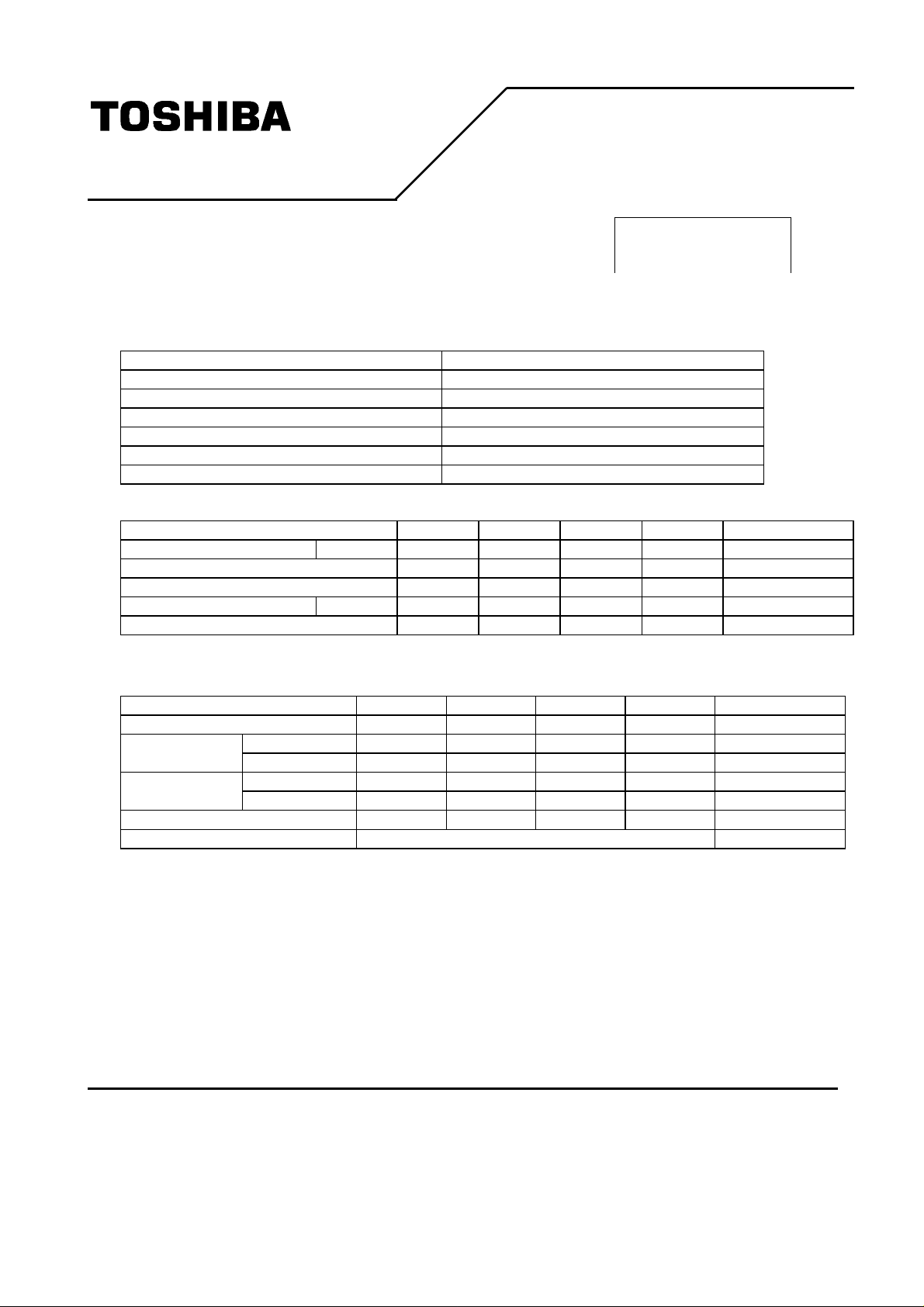
MECHANICAL SPECIFICATION
Item Specification
Dimensional Outline (typ.) (340)(W) x (257)(H) x 29max(D) (mm)
Number of Pixel 1024(W) x 768(H) pixels
Active Area 304.128(W) x 228.096(H) (mm)
Pixel Pitch 0.297(W) x 0.297(H)
Weight (2300 g)
Backlight Two CCFL, Side light
ELECTRICAL SPECIFICATION
Item Min. Typ. Max. Unit Remarks
Supply Voltage (VDD) --- 12 --- VDC
Input Signal --- 0.7 --- V
Synchronization Signal --- TTL Level --- V
Current Consumption (IDD) --- TBD --- mA
Power Consumption (Target) --- (17) --- W @200cd/m
Note 1) Not include the AC adapter unit.
75Ω terminated
(p-p)
2 1)
OPTICAL SPECIFICATION (Ta=25°°C)
Item Min. Typ. Max. Unit Remarks
Contrast Racio (CR) 100 (250) --- ---
(Upper+Lower) --- (90) --- ° Viewing Angle
(CR>=10)
Luminance --- 200 --- cd/m2
Luminance adjustment limit 30% to 100%
Note 2) Adjust by operating OSD(On Screen Display) menu.
*The information contained herein is presented only as a guide for the applications of our products. No responsibility is assumed by Toshiba
or other rights of the third parties which may result from its use. No license is granted by implication or otherwise under any patent or patent
rights of Toshiba or others.
*The information contained herein may be changed without prior notice. It is therefore advisable to contact Toshiba before proceeding with
the design of equipment incorporating this product.
(Left+Right) --- (120) --- °
(τr) L: 10-90% --- (40) --- ms Rise Response Time
(τf) L: 90-10% --- (10) --- ms Fall
2)
(1/7) 1999-12-16 (Ver. 0.1)
Page 2
LTM15C429
TENTATIVE
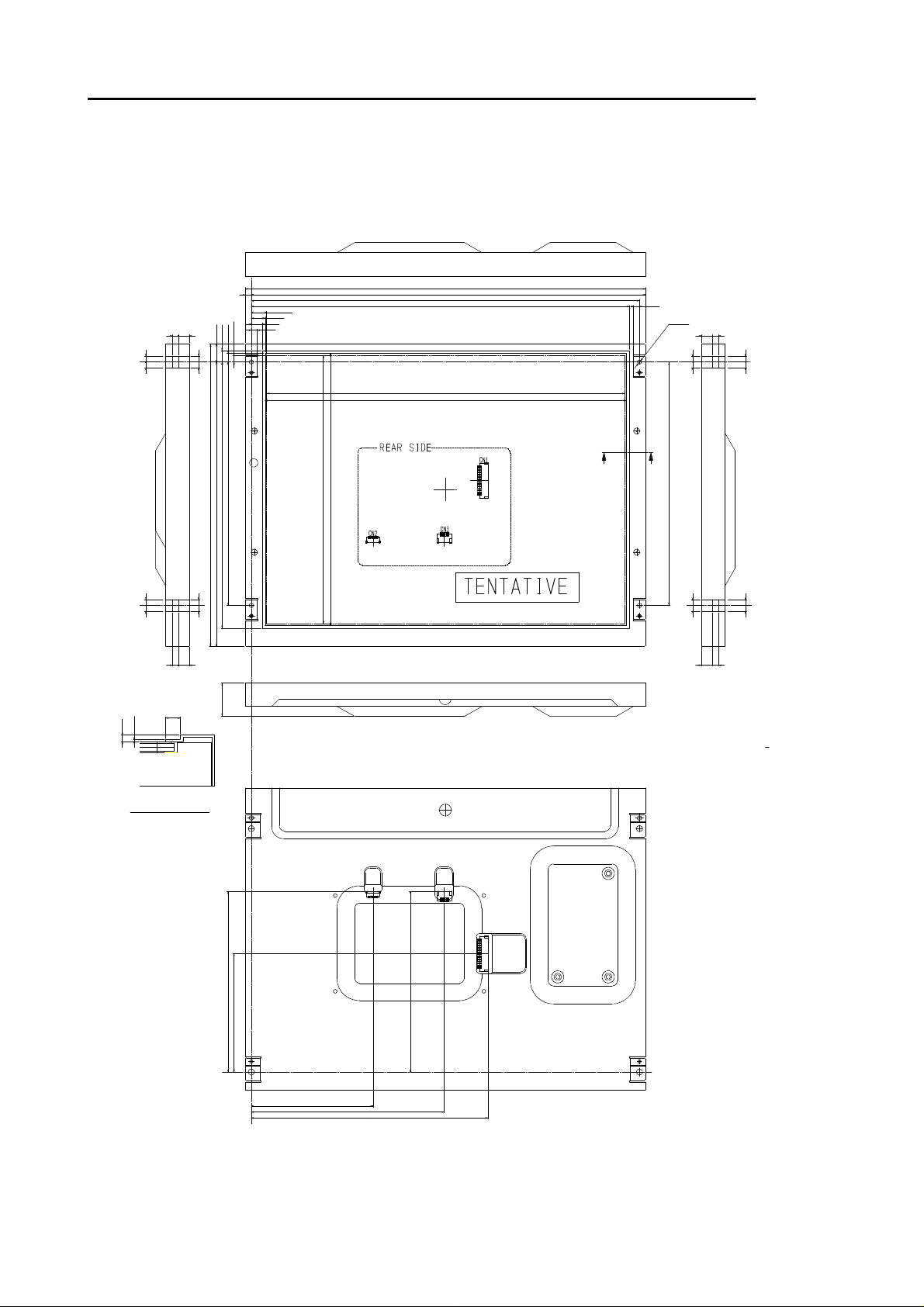
DIMENSIONAL OUTLINE
5
9.6
7.1
15.3
5.548
207
(257)
226.6
241.7
13.136
11.6
9.1
5
Unit : mm
Standard tolerance : 0.5
(340)
335
330
321.3
304.128(A.A)
307.2(B.O)
‚`
231.2(B.O)
228.096(A.A)
5
4-ƒÓ3.5
59 .559.5
5555
‚`
207
55
55 55
0.6
1.3
‚`•| ‚` ‚ƒ ‚’ ‚• ‚“ ‚“ ‚“‚… ‚ƒ ‚”‚‰ ‚•‚
55 55
59.5
2.5
29MAX
‚r‚v ‚h‚s ‚b‚g ‚b‚m
•} 1
153.7
•} 1
100.7
‚o‚n ‚v‚d‚q ‚b‚m
‚u‚h ‚c‚d ‚n ‚b‚m
•} 1
153.7
55
9.55
(2/7) 1999-12-16 (Ver. 0.1)
103.5
•} 1
•} 1
164
•} 1
201.3
Page 3
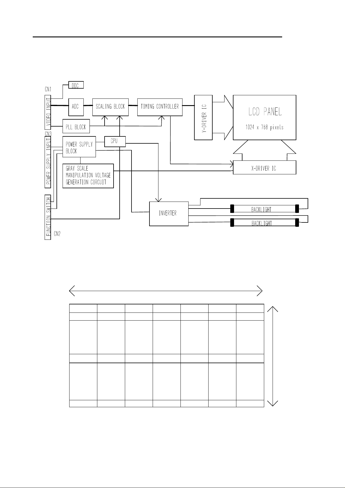
BLOCK DIAGRAM
LTM15C429
1, 1 2, 1 X2
1024 pixels
, 1 X2n, 1 1024, 1
n-1
1, 2
1, Y X
1,7768
, Y X2n, Y
2n-1
768 pixels
1024,768
(3/7) 1999-12-16 (Ver. 0.1)
Page 4

TIMING CHART
LTM15C429
(4/7) 1999-12-16 (Ver. 0.1)
Page 5

CORRESPONDED DISPLAY MODE 1)
The timing mode shown as below is standard.
VESA
Ditto
Ditto
Ditto
Ditto
Ditto
Ditto
Ditto
Ditto
Ditto
Ditto
Ditto
Ditto
Ditto
Ditto
Ditto
Displayed
Pixel
640 x 350 85.08 350 63 37.861 640
640 x 400 85.08 400 44 37.861 640
640 x 480 59.941 480 35 31.469 640
680 x 480 72.809 480 31 37.861 640
640 x 480 75.000 480 19 37.500 640
640 x 480 85.008 480 28 43.269 640
720 x 400 85.083 400 45 37.927 720
800 x 600 56.250 600 24 35.156 800
800 x 600 60.317 600 27 37.879 800
800 x 600 72.188 600 29 48.077 800
800 x 600 75.000 600 24 46.875 800
800 x 600 85.061 600 30 53.674 800
1024 x 768 60.004 768 35 48.363 1024
1024 x 768 70.069 768 35 56.476 1024
1024 x 768 75.029 768 31 60.023 1024
1024 x 768 84.997 768 39 68.677 1024
Frame Rate Vertical
Display Term
[lines] [lines] k [pixels] [pixels]
V-Back porch
+ Vsync Width
Horizontal
Scanning Time
Horizontal
Display Term
LTM15C429
H-Back porch
+ Hsync Width
160
160
144
168
184
136
180
200
216
184
240
216
296
280
272
304
Note 1) If you operate LTM15C429 with a different timing from the above specification table, please consult with Toshiba
before designing.
(5/7) 1999-12-16 (Ver. 0.1)
Page 6

INPUT SIGNAL
CN1 Video Connector
Connector : S13B-PH-SM3-TB / JST
Terminal No. Symbol Function
1 R RED Video Signal : 0.7V
2 RR RED Return
3 G GREEN Video Signal : 0.7V
4 GR GREEN Return
5 B BLUE Video Signal : 0.7V
6 BR BLUE Return
7 HS H-Sync : TTL
8 VS V-Sync : TTL
9 GND
10 SDA DDC Data
11 SCL DDC Clock
12 NC NC
13 GND
(p-p)
(p-p)
(p-p)
LTM15C429
CN2 Switch Connector
Connector : SM09B-SRSS-TB / JST
Terminal No. Symbol Function
1 GND
2 ON/OFF Power Supply ON/OFF ON:GND OFF: High impedance
3 RED Red LED Connect with anode terminal of LED
4 GREEN Green LED Connect with anode terminal of LED
5 UP Function switch “UP” Input : GND Normally : NC
6 DOWN Function switch “DOWN” Input : GND Normally : NC
7 ENTER Function switch “ENTER” Input : GND Normally : NC
8 MENU Function switch “MENU” Input : GND Normally : NC
9 NC NC
Note 2) LED Condition
Power OFF LED OFF
CN3 POWER Connector
Connector : S4B-PH-SM3-TB / JST
GREEN : Video Signal In Power ON
ORANGE : No Video
2)
2)
Terminal No. Symbol Function
1 12V Power Supply : 12V
2 12V Power Supply : 12V
3 GND GND
4 GND GND
(6/7) 1999-12-16 (Ver. 0.1)
Page 7

!
FOR SAFETY
LCD module is generally designed with precise parts to achieve light weighted thin mechanical dimensions.
In using our Modules, make certain that you fully understand and put into practice the warnings and safety precautions detailed in
Engineering Information No.EE-N001,"CAUTIONS AND INSTRUCTIONS FOR TOSHIBA LCD MODULES".
Refer to individual specifications and TECHNICAL DATA sheets (hereinafter called "TD") for more detailed technical information.
1) SPECIAL PURPOSES
A) Toshiba's Standard LCD Modules have not been customized for operation in extreme environments or for use in applications
where performance failures could be life-threatening or otherwise catastrophic.
B) Since Toshiba's Standard LCD Modules have not been designed for operation in extreme environments, they must never be
used in devices that will be exposed to abnormally high levels of vibration or shock which exceed Toshiba's published specification
limits.
C) In addition, since Toshiba Standard LCD Modules have not been designed for use in applications where performance failures
could be life-threatening or catastrophic, they must never be installed in aircraft navigation control systems (such as, but not limited
to Traffic Collision Avoidance System and Air Traffic Indicator), in military defense or weapons systems, in critical industrial
process-control systems (e.g., those involved in the production of nuclear energy), or in critical medical device or patient
life-support systems.
2) DISASSEMBLING OR MODIFICATION
DO NOT DISASSEMBLE OR MODIFY the module. It may damage sensitive parts inside LCD module, and may cause scratches
or dust on the display.
Toshiba doses not warrant the module, if customer disassembled or modified it.
3) BREAKAGE OF LCD PANEL
DO NOT INGEST liquid crystal material, DO NOT INHALE this material, and DO NOT CONTACT the material with skin, if LCD
panel is broken and liquid crystal material spills out.
If liquid crystal material comes into mouth or eyes, rinse mouth or eyes out with water immediately.
If this material contacts with skin or cloths, wash it off immediately with alcohol and rinse thoroughly with water.
4) GLASS OF LCD PANEL
BE CAREFUL WITH CHIPS OF GLASS that may cause injuring fingers or skin, when the glass is broken.
5) ELECTRIC SHOCK
DISCONNECT POWER SUPPLY before handling LCD module.
DO NOT TOUCH the parts inside LCD module and the fluorescent lamp's connector or cables in order to prevent electric shock,
because high voltage is supplied to these parts from the inverter unit while power supply is turned on.
6) ABSOLUTE MAXIMUM RATINGS AND POWER PROTECTION CIRCUIT
DO NOT EXCEED the absolute maximum rating values under the worst probable conditions caused by the supply voltage variation,
input voltage variation, variation in parts' constants, environmental temperature, etc., otherwise LCD module may be damaged.
Employ protection circuit for power supply, whenever the specification or TD specifies it.
Suitable protection circuit should be applied for each system design.
7) DISPOSAL
When dispose LCD module, obey to the applicable environmental regulations.
LTM15C429
(7/7) 1999-12-16 (Ver. 0.1)
 Loading...