

Page 1

To :
This specification is only used for discussing the included items.
You haven’t to approve this specification.
When we shall agree the specification, we will issue the formal one.
SPECIFICATION(TENTATIVE)
FOR
Toshiba Matsushita Display Technology TFT-LCD MODULE
LTA170C07RF
LTA170C07RF-01
DATE OF ISSUE : 2003-06-18
TV/PC/Monitor-Use Marketing & Engineering Group2
TV/PC/Monitor-Use Marketing & Engineering Dept.
AVC-Use LCD Division
Toshiba Matsushita Display Technology Co.,Ltd.
1-9-2, Hatara-cho, Fukaya-shi, Saitama, 366-0032, JAPAN (Toshiba Fukaya Operations)
Page 2
18
Revision History
Date Sheet
’03-6-
(New)
NEW
Specification No. TENTATIVE
Item Old New Reason
TENTATIVE
SPECIFICATIONS
-
-
Sheet 1
-
Toshiba Matsushita Display Technology Co.,Ltd
Date: 2003-06-18
Date: - -
←# Special ←& Addition ← Change
New No. LTA170C07RF-01
Old
No.
Page 3
Specification No. TENTATIVE
Sheet 2
Caution and Handling Precaution
For your end users' safety, it is strongly advised that the items with "Ú" should be included in the instruction
manual of the system which may be issued by your organization.
For Safety
Warning
1) SPECIAL PURPOSES
a) Toshiba Matsushita Display Technology’s Standard LCD modules have not been customized for operation
in extreme environments or for use in applications where performance failures could be life-threatening or
otherwise catastrophic.
b) Since they have not been designed for operation in extreme environments, they must never be used in
devices that will be exposed to temperatures above 50 degrees Celsius or below 0 degrees Celsius, to
X-ray or Gamma-ray radiation, or to abnormally high levels of vibration or shock which exceed Toshiba
Matsushita Display Technology’s specification limits.
c) In addition, since Toshiba Matsushita Display Technology’s Standard LCD modules have not been
designed for use in applications where performance failures could be life-threatening of catastrophic, they
must never be installed in aircraft navigation control systems (such as, but not limited to Traffic Collision
Avoidance System and Air Traffic Indicator), in military defense or weapons systems, in critical industrial
process-control systems (e.g., those involved in the production of nuclear energy), or in critical medical
device or patient life-support systems.
2) ELECTRIC SHOCK
DISCONNECT POWER SUPPLY before handling LCD modules. In order to prevent electric shock, DO NOT
TOUCH the electrode part, cables, connectors, and the fluorescent lamp’s (hereinafter called “FL”) circuit part
of a module in which FL tubes are built in as a light source of a backlight or a front light. High voltage is
supplied to these parts while power supply is turned on.
3) FL CABLE CONNECTION
Make sure to insert the module FL connector to the inverter connector in correct position and correct
polarity. If incorrect, this may cause smoke or burn of electrical parts by high voltage of FL circuit. If there is
a possibility that the connector has been inserted incorrectly, re-insert the connector only after you confirm
the module and FL power is completely off. When disconnecting the connector, do not pull on the cable.
DO NOT USE the mating FL connector which Toshiba Matsushita Display Technology does not
specify. Otherwise, Toshiba Matsushita Display Technology shall not be liable for any damages
caused by the connector.
Caution
1) Ú DISASSEMBLING OR MODIFICATION
DO NOT DISASSEMBLE OR MODIFY the modules.
Sensitive parts inside LCD module may be damaged, and dusts or scratches may mar the displays.
Toshiba Matsushita Display Technology does not warrant the modules, if customer disassembled or
modified them.
Toshiba Matsushita Display Technology Co.,Ltd
Date: 2003-06-18
Date: - -
←# Special ←& Addition ← Change
New No. LTA170C07RF-01
Old
No.
Page 4

Specification No. TENTATIVE
Sheet 3
2) Ú BREAKAGE OF LCD PANEL
DO NOT INGEST liquid crystal material, DO NOT INHALE this material, and DO NOT PERMIT this material
to contact the skin, if glass of LCD panel is broken.
If liquid crystal material contacts the skin, mouth or clothing, take the following actions immediately.
In case contact to the eye or mouth, rinse with large amount of running water for more than 15 minutes. In
case contact to the skin or clothing, wipe it off immediately and wash with soap and large amount of running
water for more than 15 minutes. The skin or closing may be damaged if liquid crystal material is left adhered.
In case ingestion, rinse out the mouth well with water. After spewing up by drinking large amount of water, get
medical treatment.
3) Ú GLASS OF LCD PANEL
BE CAREFUL WITH CHIPS OF GRASS that may cause injuring fingers or skin, when the glass is broken.
Since FL is also made of glass, when FL is built in, handle it with due caution as well.
4) ABSOLUTE MAXIMUM RATINGS
DO NOT EXCEED the absolute maximum rating values under the worst probable conditions caused by the
supply voltage variation, input voltage variation, variation in parts' constants, environmental temperature,
etc., otherwise LCD module may be damaged.
5) POWER PROTECTION CIRCUIT
Employ protection circuit for power supply, whenever the specification specifies it.
A suitable protection circuit should be applied, based on each system design.
6) DISPOSAL
Always comply all applicable environmental regulations, when disposing of LCD module.
7) EDGES OF PARTS
Be careful with handling the metal flame (bezel) of a module. Even though burr disposal treatment is performed, it may cause
injuring. Be careful with edges of glass parts and touch panel identically. For designing the system, give special consideration
that the wiring and parts do not touch those edges.
8) Ú LUMINANCE DECREASE OF FL
When FL becomes extremely dark and its color changes from white to pink, stop the use of the module
immediately. FL, at the end of its life with its discharge color turns into pink as the characteristics of FL, may
adversely affect the module at the end part of FL due to temperature raising caused by depletion of the
mercury which is contained in FL tube, or may have a possibility of breakage.
Toshiba Matsushita Display Technology Co.,Ltd
Date: 2003-06-18
Date: - -
←# Special ←& Addition ← Change
New No. LTA170C07RF-01
Old
No.
Page 5

Specification No. TENTATIVE
Sheet 4
For Designing the System
2-1 DESIGNING ENCLOSURE
1) MECHANICAL DIMENSIONS
Refer to the individual specification for LCD module's mechanical dimensions.
2) MOUNTING HOLES
LCD module should be assembled to the system by using all mounting holes specified in the individual
specification with the specified screws.
In addition, some modules may not be necessary to use all the mounting holes. Make comprehensive
judgments on the entire system.
3) Ú BENDING / TWISTING
Make sure to design the enclosure that bending/twisting forces are not applied to LCD module during and
after the installation into the system.
4) GASES FROM SETTING MATERIAL
Some plastic materials and shock absorbing materials (rubber) used in the system may generate gases that
may cause the deterioration of the polarizer laminated on LCD’s panel or internal parts of the module. Prior
confirmation is required.
5) GASES FROM PACKAGING MATERIAL
Some materials used for packaging (for which sulfuric acid is used in the recycling process) generate gases
that may cause the deterioration of the polarizer laminated on LCD’s panel or internal parts of the module.
Prior confirmation is required.
2-2 DESIGNING POWER SUPPLIES AND INPUT SIGNALS TO LCD MODULE
1) CAPACITY OF POWER SUPPLY
Refer to individual specification for details for capacity of power supply, and apply some protection circuit
including fuses for power supply lines.
2) SEQUENCE OF POWER SUPPLIES AND INPUT SIGNALS
Power supply lines should be designed as follows.
Power supplies should always be turned on before the input signals are applied to LCD module, and the
input signals should be disconnected before power supplies are turned off.
The detailed sequence of power supplies and signals are described in the individual specification.
In addition, refer to individual specifications for unused terminals.
3) FL CABLE CONNECTION
Make sure to connect correctly high-voltage wire and low-voltage wire between FL tube and inverter unit.
If high-voltage wire and low-voltage wire are connected incorrectly, it may cause insufficient brightness or
unstable operation of FL, and smoke or burn of the parts.
4) PREVENTION OF IMAGE STICKING
Design the system not to display same pattern for a long time in order to prevent image sticking on the
panel. Note that incorrect sequence of power supplies and input signals may cause the sticking on the
panel, too.
Toshiba Matsushita Display Technology Co.,Ltd
Date: 2003-06-18
Date: - -
←# Special ←& Addition ← Change
New No. LTA170C07RF-01
Old
No.
Page 6

Specification No. TENTATIVE
5) GROUNDING OF METAL FRAME
Grounding of metal frame of LCD module is generally effective to prevent radiation interference from the
system design.
However, the necessity of grounding, or effective grounding method should be dependent on each system
design.
2-3 DESIGNING FOR BETTER VISIBILITY
1) PANEL ANGLE
Visibility of LCD module deeply depends on the viewing directions. The position and the angle of LCD
module in the system should be designed so that the best visibility can be obtained at the actual usage.
2) WINDOW OPENING
Dimensions of window opening of the system's enclosure should be designed as smaller than "Viewing
Area" and larger than "Active Area" specified in individual specification in order to obtain better
appearance.
3) PROTECTIVE COVER
In case of severe environmental condition like outdoor usage, a proper transparent protective cover(lens)
over LCD module is recommended to apply in order to prevent scratches, and invasion of dust, water, etc.,
from the system's window onto LCD module.
Ultra-violet ray cut filter is recommended to apply onto LCD module for outdoor operation. Strong
ultra-violet ray may cause damage the panel. However, in that case, transmittance-luminance will decrease.
Careful selection of material is required.
2-4 DESIGNING FL POWER SUPPLY CIRCUIT
Input FL starting voltage(VSFL) should be longer than two seconds. If it were not, it may cause unstable
operation of FL.
Inverter should be design to stop output when the inverter is no-load to FL tubes (due to breakage of FL, etc.)
to prevent high-voltage generation.
When high voltage is applied to FL continuously without normal operation of FL (due to output leakage within
FL wiring circuit, etc.) it may cause smoke or burn. To prevent excess current, design the inverter with a
protection circuit such as a current limiter (excess current detection) to stop inverter output.
Sheet 5
For Installation in Assembly
3-1 ESD (ELECTRO-STATIC DISCHARGE) PREVENTION
The C-MOS LSIs used in LCD module is very sensitive to ESD. The following caution should be taken
when installing LCD module to an enclosure of the system in order to prevent damage of C-MOS LSIs
used in LCD module.
1) HUMIDITY
Ambient humidity of working area is recommended to be higher than 50%RH in order to avoid ESD.
2) GROUNDING
2-1) Grounded electro-conductive mats are recommended to be covered on the floor of working area and
surface of working benches.
2-2) The grounding should be done through a resister of 0.5-1M ohms in order to prevent spark of ESD.
Toshiba Matsushita Display Technology Co.,Ltd
Date: 2003-06-18
Date: - -
←# Special ←& Addition ← Change
New No. LTA170C07RF-01
Old
No.
Page 7

Specification No. TENTATIVE
Sheet 6
2-3) Person handling LCD modules should be grounded with wrist band.
2-4) Tools like soldering iron and screw drivers and working benches should be grounded.
3) IONIZER
Using ionizer (an antistatic blower) is recommended at working area in order to reduce electro-static
voltage.
4) REMOVING PROTECTION FILM
When removing protection film from LCD panel, peel off the film slowly (more than three seconds) from the
edge of the panel with round-ended tweezers or adhesive tape while blowing with ionizer toward the peeling
face to minimize ESD which may damage electrical circuit.
5) Be careful with touching metal portion of testing instruments in order to prevent unnecessary ESD.
6) Do not touch the electrode area of PCB and electrical parts like LSI, capacitor, connector pin, etc.
3-2 DUST AND STAIN PREVENTION
1) WORKING AREA
Reduce dust level in working area. Especially the level of metal particle should be decreased, otherwise
electrical circuit in LCD module may be damaged due to short circuit by metal particles.
2) PROTECTION FILM
LCD module may be shipped with "protection film" on LCD panel in order to prevent from scratches and
dust.
It is recommended to remove the film at later process of assembling.
3) FINGER PRINT
Use finger stalls or soft and dust-free gloves in order to keep clean appearance of LCD module when
handled for incoming inspection and assembly.
4) Ú WIPING OFF DUST ON THE PANEL
When LCD panel becomes dirty, wipe the panel surface off softly with absorbent cotton or another soft
cloth.
If necessary, breathe upon the panel surface and then wipe off immediately and softly again.
If the dirt can not be wiped off, follow the instructions described in individual specification.
Be careful not to spill organic solvents into the inside of LCD module. The solvents may damage driver IC
and PCB area used inside module.
The polarizer laminated to LCD panel and adhesives may be damaged by the solvents, so do not use any
organic solvents for wiping off LCD panel.
5) ADHESIVE ON LCD PANEL
Be careful not to attach adhesive, grease, etc., on LCD panel, because it is difficult to remove them without
any damages on LCD panel.
Toshiba Matsushita Display Technology Co.,Ltd
Date: 2003-06-18
Date: - -
←# Special ←& Addition ← Change
New No. LTA170C07RF-01
Old
No.
Page 8

Specification No. TENTATIVE
Sheet 7
6) Ú WATER SPOTS ON THE PANEL
Avoid the dewing or water condensation.
Wipe off a spot or spots of water or mist on LCD panel softly with absorbent cotton or another cloth as soon
as possible if happened, otherwise discoloration or stain may be caused.
3-3 BENDING / TWISTING OF LCD MODULE DURING ASSEMBLY
1) INSTALLING LCD MODULE TO THE ENCLOSURE
Do not bend or twist LCD module even momentary when LCD module is installed into an enclosure of the
system.
2) FASTENING SCREWS
Fasten screws for mounting holes uniformly, otherwise bending / twisting force may be applied to LCD
module.
3) INTERFACE / FL CABLES
Do not fasten screws, with catching interface cables or FL cables between LCD module and the enclosure.
This may cause bending of LCD module, or become the cause of a failure by damaging cables.
3-4 MECHANICAL FORCES
1) Ú STRONG MECHANICAL SHOCK
Refrain from strong mechanical shock like dropping from the working bench or knocking against hard
object.
These may cause panel crack, damage of FL or other mis-operation.
2) Ú EXCESSIVE FORCE
Refrain from excessive force like pushing the surface of LCD panel. This may cause scratches or breakage
of the panel, or a failure of the module.
3) Ú SCRATCHES ON THE PANEL
Do not put heavy object such as tools, books, etc., and do not pile up LCD modules.
Be careful not to touch surface of the polarizer laminated to the panel with any hard and sharp object. The
polarizer is so soft that it can be easily scratched, even the protect film covers it.
4) CONNECTORS
When inserting or disconnecting the connectors to LCD module, be sure not to apply force against PCB nor
connecting cables, otherwise internal connection of PCB and TAB drivers may be damaged.
5) FL CABLES
Be careful not to pull the FL cables in order to avoid mechanical damage in FL lamp and soldering area.
While mounting, do not bind or twist the FL cables, or the Lamp current may not be applied as designed.
Toshiba Matsushita Display Technology Co.,Ltd
Date: 2003-06-18
Date: - -
←# Special ←& Addition ← Change
New No. LTA170C07RF-01
Old
No.
Page 9

Specification No. TENTATIVE
3-5 OPERATION
Be sure that the following caution should be taken under assembly and inspection of the system.
1) POWER SUPPLY
Power supplies should always be turned off in connecting process.
Do not connect or disconnect the power cables and connectors with power applied to LCD module.
2) INPUT SIGNAL
The signal should be applied after power supplies are turned on.
The signal should be removed before power supplies are turned off.
The detailed sequence of power supplies and signals are described in individual specifications.
Sheet 8
For Transportation and Storage
1) TEMPERATURE
Do not store LCD modules in high temperature, especially in high humidity for a long time (approximately
more than one month).
It is strongly recommended to store LCD modules where the temperature is in the range of 0 to 35 degrees
Celsius and the humidity is lower than 70%.
2) LOW TEMPERATURE
Liquid crystal material may be coagulated and LCD panel may be damaged at the lower temperature than
storage temperature range described in individual specification.
3) ULTRA VIOLET RAY
Store LCD module without exposure to direct sunlight or fluorescent lamps in order to prevent the module
from strong ultra violet ray.
4) CLEANLINESS
Keep the module in clean place, because any dust, hard particle may damage the polarizer, or dust
invades the inside of the module.
5) Ú CONDENSATION OF WATER
Avoid condensation of water on LCD module, otherwise it may cause mis-operation or defects. Keep away
LCD module from such ambient.
6) PACKAGING
In case of transportation or storage after opening the original packaging, LCD modules are recommended
to be repacked into the original packaging with the same method, especially with same kind of desiccant.
Toshiba Matsushita Display Technology Co.,Ltd
Date: 2003-06-18
Date: - -
←# Special ←& Addition ← Change
New No. LTA170C07RF-01
Old
No.
Page 10

Specification No. TENTATIVE
- CONTENTS -
Revision History Sheet 1
Caution and Handling Precaution 2
1. Scope 10
2. Product Specifications 10
2.1 General Specifications
2.2 Absolute Maximum Ratings 11
2.3 Mechanical Specifications
2.3.1 Weight
2.3.2 Dimensional Outline 12-13
2.4 Electrical Specifications 14
2.4.1 Circuit Diagram
2.4.2 Sequence of Power Supplies and Signals
2.4.3 Timing Chart 15
2.4.4 Timing Specifications 16
2.4.5 Interface Connector 17
2.4.6 Register map 19-20
2.4.7 Colors Combination Table 21
3. Recommended Operating Conditions 22
4. Electrical Characteristics 23
4.1 Test Conditions
4.2 Specifications
5. Optical Characteristics 24
5.1 Test Conditions
5.2 Optical Specifications
6. Quality 24
6.1 Inspection AQL
6.2 Test Conditions
6.3 Dimensional Outline
6.4 Appearance Test 26
6.4.1 Test Conditions
6.4.2 Specifications
6.5 Display Quality 27
6.5.1 Test Conditions
6.5.2 Specifications
6.6 Reliability Test 28
6.6.1 Test Conditions
6.6.2 Specifications
6.7 Labels 29
7. Lifetime 30
7.1 Module
7.2 Test Conditions
8. Packaging 31
8.1 Carton
9. Warranty 32
10. Measuring Method 32
10.1 Measuring Systems
10.2 Measuring Methods 33
Sheet 9
Toshiba Matsushita Display Technology Co.,Ltd
Date: 2003-06-18
Date: - -
←# Special ←& Addition ← Change
New No. LTA170C07RF-01
Old
No.
Page 11
1 2
(Dots)
G B
Specification No. TENTATIVE
1. Scope
This specification is applicable to Toshiba Matsushita Display Technology's 43 cm diagonal size TFT-LCD module
"LTA170C07RF" designed for TV.
2. Product Specifications
2.1 General Specifications
Item Specifications
Display Mode TN color (253 gray scales, 16,194,277 colors)
Transmissive type, Normally white
Viewing Direction 6 o'clock (in direction of maximum contrast)
Driving Method TFT active matrix
Input Signals
Dimensional Outline
Active Area
Viewing Area
Number of Pixels
Pixel Pitch
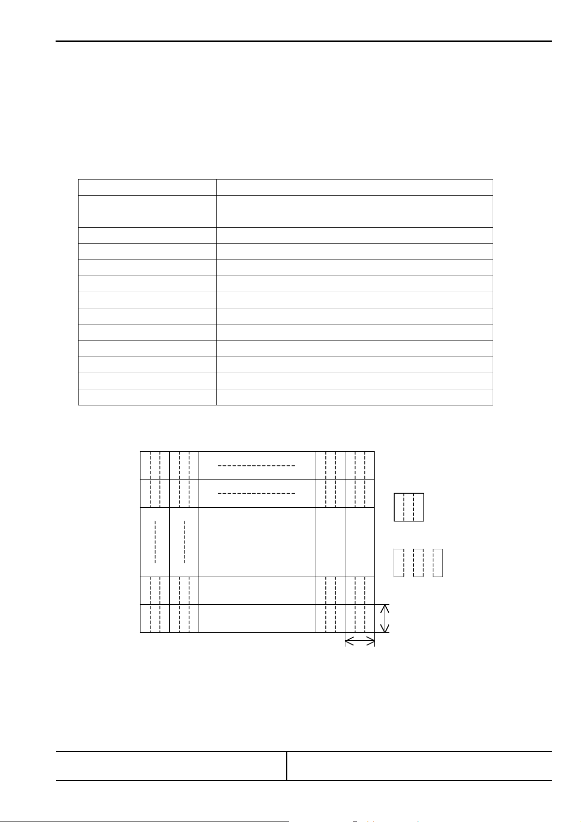
Pixel Arrangement RGB vertical stripes 1)
Surface Treatment Low Reflection & Anti-glare hard coat on LCD surface
Backlight 4 cold-cathode fluorescent lamps (L-Type)
Note 1) Display area address is as follows.
R G B
R G B
R G B
R G B
R G B
R G B
R G B
R G B
1
2
479
480
C-MOS 8Bit × RGB
385 (W) × 303 (H) × 17.5 (D) (mm)
343.68 (W) × 261.60 (H) (mm)
349 (W) × 267 (H) (mm)
640 (W) × 480 (H) 1)
0.545 (W) × 0.537 (H) (mm) 1)
R G B
R G B
R G B
R G B
R G B
R G B
R G B
R G B
R G B
R
0.446mm
0.446mm
: pixel
: Sub-pixel
Sheet 10
Toshiba Matsushita Display Technology Co.,Ltd
Date: 2003-06-18
Date: - -
New No. LTA170C07RF-01
Old
←# Special ←& Addition ← Change
No.
Page 12

Specification No. TENTATIVE
Sheet 11
2.2 Absolute Maximum Ratings 1)
Item Symbol Min. Max. Unit Checked Terminal 4)
Supply Voltage VDD -0.3 +6.0 V VDD - GND
Input Voltage of Signals VIN -0.3 VDD+0.3 V
FL Driving Voltage VFL 0 2.0 kV(rms)
FL Driving Frequency fFL 0 100 kHz
Operating Ambient Temperature 2) TOP 0 +50
Operating Ambient Humidity 2) HOP 10 90 %(RH)
Storage Temperature 2) T
Storage Humidity 2) H
Operating Temperature for Panel 3) - 0 +60
Note 1) Do not exceed the maximum rating values under the worst probable conditions taking into account the supply voltage
variation, input voltage variation, variation in part constants, and ambient temperature and so on. Otherwise the module
may be damaged.
2) Wet bulb temperature should be 39°C (Max), and no condensation of water. See figure below.
3) The surface temperature caused by self heat radiation of cell itself is specified on this item.
4) Refer to 2.4.5
-20 +60
STG
10 90 %(RH)
STG
°C
°C
°C
80%90%
60%
40%
Wet Bulb
Temperature [ C]
-20
10
0
0
10 20 30 40 50 60 70 80
Dry Bulb Temperature [ C]
30
20
40
50
20%
10%
]
)
H
R
(
%
[
y
t
i
d
i
m
u
H
Storage
Operation
2.3 Mechanical Specifications
2.3.1 Weight
2000 ± 100g
Toshiba Matsushita Display Technology Co.,Ltd
Date: 2003-06-18
Date: - -
←# Special ←& Addition ← Change
New No. LTA170C07RF-01
Old
No.
Page 13

Specification No. TENTATIVE
Sheet 12
2.3.2 Dimensional Outline Unit: mm
(Front figure) Standard Tolerance: 0.5
Toshiba Matsushita Display Technology Co.,Ltd
Date: 2003-06-18
Date: - -
←# Special ←& Addition ← Change
New No. LTA170C07RF-01
Old
No.
Page 14

Specification No. TENTATIVE
Sheet 13
(Back figure) Unit: mm
Standard Tolerance: 0.5
Toshiba Matsushita Display Technology Co.,Ltd
Date: 2003-06-18
Date: - -
←# Special ←& Addition ← Change
New No. LTA170C07RF-01
Old
No.
Page 15

nce of Power Supplies and Signals
Unit
CN5
I/F Connector
Panel
Driver
Driver
CN3
CN2
CN4
CCFL
Input signal
Specification No. TENTATIVE
2.4 Electrical Specifications
2.4.1 Circuit Diagram
CN1
DC/DC
Converter
Controller
Liquid Crystal Panel
640 x 480 pixels
Y-
2.4.2 Seque
Note (1): OFF time (<=0.5V) should be maintained more than 150ms.
300 ms (Min)
50 ms (Max)
VDD
V
DD
0 ms (Min)
30 ms (Max)
0.5V
16 ms (Min)
4.5V
TON=460 us
X-Diver
Backlight
0 ms (Min)
Y-
300 ms (Min)
Note (1)
0 ms (Min)
30 ms (Max)
Sheet 14
Toshiba Matsushita Display Technology Co.,Ltd
Date: 2003-06-18
Date: - -
←# Special ←& Addition ← Change
New No. LTA170C07RF-01
Old
No.
Page 16

Hs
2.4.3 Timing Chart
Specification No. TENTATIVE
TV
Sheet 15
Vs
Vs
Hs
Vs
Tvp
Thp
Tvb
Thb
TH
Tvd
Thd
VIH
VIL
Tvf
Thf
Hs
RGB-Data
Clk
Tvpd
Tds
Ths
Tdh
Thh
VIH
VIL
Tch
VIH
VIL
VIH
VIL
Tcl
Toshiba Matsushita Display Technology Co.,Ltd
Date: 2003-06-18
Date: - -
←# Special ←& Addition ← Change
New No. LTA170C07RF-01
Old
No.
Page 17

Specification No. TENTATIVE
Sheet 16
2.4.4 Timing Specifications
1) 2) 3) 4)
Item Symbol Min. Typ. Max. Unit Remarks
Clock
(Clk)
Horizontal
(Hs)
Vertical
(Vs)
Frequency Fck 17 28.6 31.5 MHz
High time Tch 10 - - nsec
Low time Tcl 10 - - nsec
Setup time Tds 6 - - nsec DATA
Hold time Tdh 7 - - nsec
Polarity - Negative -
Setup time Ths 6 - - nsec
Hold time Thh 7 - - nsec
TH
including Blanking
Pulse width Thp 1 69 Note 1 Fck
Back porch Thb 12 104 Note 1 Fck
Display term Thd 640 Fck
Front porch Thf 1 46 - Fck
Polarity - Negative -
Phase shift Tvpd -1 0 1 Fck
TV
including Blanking
Pulse width Tvp 1 6 Note 1 TH
Back porch Tvb 2 46 Note 1 TH
Front porch Tvf 1 29 - TH
Display term Tvd 480 TH
720 910 1620 Fck Total Period
28.8 31.8 -
485 525 720 TH Frame Period
- 16.7 20.0 msec
µsec
Note 1) Thp + Thb<254, Tvp + Tvb<254
Note 2) If Hs and Vs signal is fixed to "H" or "L" level for certain period while Clock is supplied, the panel displays black with some
flicker.
Note 3) If Clock is fixed to "H" or "L" level for certain period while Hs and Vs is supplied, the panel may be damaged.
Note 4) Please adjust LCD operating signal timing and FL driving frequency, to optimize the display quality.
There is a possibility that flicker is observed by the interference of LCD operating signal timing and FL driving condition
(especially driving frequency), even if the condition satisfies above timing specifications and recommended operating
conditions shown in 3.
Note5) Do not make TH and TV fluctuate.
If TH and TV are fluctuate, the panel displays error.
Note6) In case of using the long frame period, the deterioration of display quality, noise etc. may be occurred.
Note7) Clock count of each Horizontal Scanning Time should be always the same.
V-Blanking period should be “n” X “Horizontal Scanning Time”. (n: integer)
Frame period should be always the same.
Toshiba Matsushita Display Technology Co.,Ltd
Date: 2003-06-18
Date: - -
←# Special ←& Addition ← Change
New No. LTA170C07RF-01
Old
No.
Page 18

Specification No. TENTATIVE
2.4.5 Interface Connector
CN1 INPUT SIGNAL
Connector : IL-FHR-BF50S-HF / JAE
Mating Connector : TBD / JAE
Terminal No. Symbol Function
1 GND
2 Clk Clock
3 GND
4 Vs Vertical Sync.
5 Hs Horizontal Sync.
6 1) NC
7 GND
8 R0 Red Display Data 0 (LSB)
9 R1 Red Display Data 1
10 R2 Red Display Data 2
11 R3 Red Display Data 3
12 GND
13 R4 Red Display Data 4
14 R5 Red Display Data 5
15 R6 Red Display Data 6
16 R7 Red Display Data 7 (MSB)
17 GND
18 G0 Green Display Data 0 (LSB)
19 G1 Green Display Data 1
20 G2 Green Display Data 2
21 G3 Green Display Data 3
22 GND
23 G4 Green Display Data 4
24 G5 Green Display Data 5
25 G6 Green Display Data 6
26 G7 Green Display Data 7 (MSB)
27 GND
28 B0 Blue Display Data 0 (LSB)
29 B1 Blue Display Data 1
30 B2 Blue Display Data 2
31 B3 Blue Display Data 3
32 GND
33 B4 Blue Display Data 4
34 B5 Blue Display Data 5
35 B6 Blue Display Data 6
36 B7 Blue Display Data 7 (MSB)
37 GND
38 GND
39 REGEN After I2C data input, it is supplied to 2nd register at internal V-latch signal
by “H”-level of this pin input during 1Vs period.
40 2) INV Input Data Inversion Control: GND: normal, VDD: Data Inversion
41 2) GND
42 2) SCL I2C Clock
43 2) SDA I2C Data
44 VDD Power Supply : +5.0V
45 VDD Power Supply : +5.0V
46 VDD Power Supply : +5.0V
47 VDD Power Supply : +5.0V
48 1) NC
49 1) NC
50 GND
Note 1) NC terminal should be open.
Note 2) In case of using 6bit input data, please use higher 6bit (bit7-bit2).
In this case, it is recommended to fix bit0 and bit1 on GND.
Sheet 17
Toshiba Matsushita Display Technology Co.,Ltd
Date: 2003-06-18
Date: - -
←# Special ←& Addition ← Change
New No. LTA170C07RF-01
Old
No.
Page 19

Specification No. TENTATIVE
CN2, 3, 4, 5 CCFL POWER SOURCE
Connector: BHSR-02VS-1 / JAPAN SOLDERLESS TERMINAL MFG CO., LTD.
Mating Connector: SM02B-BHSS-1 / JAPAN SOLDERLESS TERMINAL MFG CO., LTD.
Terminal No. Symbol Function
1 V
2 V
CCFL Power Supply (high voltage)
FLH
CCFL Power Supply (low voltage)
FLL
Sheet 18
Toshiba Matsushita Display Technology Co.,Ltd
Date: 2003-06-18
Date: - -
←# Special ←& Addition ← Change
New No. LTA170C07RF-01
Old
No.
Page 20

1
STV ADDRESS (7:0)
Black Line FRC Level: Black line level control by
t Position adjustment
for internal patter (setup X 64)
internal patter (setup X 64)
nal pattern, and
2.4.6 I2C Register Map
Address
0 00 STH ADDRESS (7:0) Horizontal start position spec. (CLK) 10110101 10111100
2 02
3 03 CTL Width (7:0)
4 04
5 05 R INTEND (7:0)
6 06
7 07 For Black Belt CTL Width (7:0)
8 08 STOP Signal Control (7:0)
9 09
12 0C
13 0D
14 0E
15 0F SIG LEVEL
16 10 DIN 0p (7:0)
17 11 DIN 32p (7:0)
18 12 DIN 64p (7:0)
19 13 DIN 96p (7:0)
20 14 DIN 128p (7:0)
21 15 DIN 160p (7:0)
22 16 DIN 192p (7:0)
23 17 DIN 224p (7:0)
24 18 DIN 256p (7:0)
25 19
26 1A DIN 0p (7:0)
27 1B DIN 32p (7:0)
28 1C DIN 64p (7:0)
29 1D DIN 96p (7:0)
30 1E DIN 128p (7:0)
31 1F DIN 160p (7:0) Gamma GEF setup (160, G) 10110110
32 20 DIN 192p (7:0) Gamma GEF setup (192, G) 11000111
33 21 DIN 224p (7:0) Gamma GEF setup (224, G) 11011000
34 22 DIN 256p (7:0) Gamma GEF setup (256, G) (LSB7Bit:validity) 01110011
35 23 G_Gm_th: G_Gamma Through 0: Through, 1:ON
36 24
b7 b6 b5 b4 b3 b2 b1 b0
01
CTL Setup all (7:4) OEV Hold (3:0)
OEV Setup (7:4) CKV Setup (3:0)
H Start Position H: End Position
V: Start Position V: End Position
R ON G ON B ON
R_Gm
th
G_Gm
th
TVD
SEL
Black Line
FRC Level
Data Initial Value Sub
CENT
DIN 0p (7:0)
Inite
State
ON
OFF
Black Line Level
Win
ON
R_Gm Offset (6:0)
G_Gm Offset (6:0)
SIG SEL (3:0)
Specification No. TENTATIVE
Vertical start position spec. (Hs) 00110010 00101000
CTL Setup all: CTL ON Phase setup
OEV Hold: Gate ON Width setup
CTL Width: CTL ON Width setup 00110101 00110010
OEV Setup: Gate ON Phase setup
CKV Setup: Gate ON Clock Phase setup
R INTEND: Souce scan Interval setup 00010111 00110011
DI OFF: DI stop 0: DI=ON, 1: DI=OFF
DI
OFF
UD LR
UD: Up/Down Reversal 0:Up, 1: Reversal
LR: Right/Left Reversal 0:Right, 1: Reversal
Inite State OFF: 0:normal, 1: Inite State OFF
Sausce signal output time in centering mode 00110101
Timing control for V Blancking’s gate voltage 11010110
1/256 Gray scale setp
Black Line Level: control of center Gray Scale
H Start Position: Horizontal star
for internal patter (setup X 64)
H end Position: Horizontal end Position adjustment
for internal patter (setup X 64)
V Start Position: Vertical start Position adjustment
V end Position: Vertical end Position adjustment for
R_ON: R signal control 0:R=L, 1: R=input value
G_ON: G signal control 0:G=L, 1: G=input value
B_ON: B signal control 0:B=L, 1: B=input value
Win_ON: Display window control for internal pattern
0: No-window, 1: Window
SIG_SEL: Internal patten select
Gray scale level control for inter
Black level contorol
Gamma REF setup (0, R) 00000000
Gamma REF setup (32, R) 00110011
Gamma REF setup (64, R) 01100000
Gamma REF setup (96, R) 10000100
Gamma REF setup (128, R) 10100000
Gamma REF setup (160, R) 10110110
Gamma REF setup (192, R) 11000111
Gamma REF setup (224, R) 11011000
Gamma REF setup (256, R) (LSB7Bit:validity) 01110011
R_Gm_th: R_Gamma Through 0: Through, 1:ON
R_Gm_Offset: R_Gamma offset setup
Gamma GEF setup (0, G) 00000000
Gamma GEF setup (32, G) 00110011
Gamma GEF setup (64, G) 01100000
Gamma GEF setup (96, G) 10000100
Gamma GEF setup (128, G) 10100000
G_Gm_Offset: G_Gamma offset setup
Gamma BEF setup (0, B) 00000000
Sheet 19
Contents
normal wide
00101100 00101001
01100110
00000000
00000000
00100100
00100100
11100000
10000000
10000000
10000000
Toshiba Matsushita Display Technology Co.,Ltd
Date: 2003-06-18
Date: - -
←# Special ←& Addition ← Change
New No. LTA170C07RF-01
Old
No.
Page 21

Specification No. TENTATIVE
37 25
38 26
39 27
40 28
41 29 DIN 160p (7:0) Gamma BEF setup (160, B) 10110110
42 2A DIN 192p (7:0) Gamma BEF setup (192, B) 11000111
43 2B DIN 224p (7:0) Gamma BEF setup (224, B) 11011000
44 2C DIN 256p (7:0) Gamma BEF setup (256, B) (LSB7Bit:validity) 01110011
45 2D B_Gm_th: B_Gamma Through 0: Through, 1:ON
46 2E Rdc: EMI Function On/Off (Reduce) 0: OFF, 1: ON
8Bit/6Bit: FRC Function On/Off 0: OFF, 1: ON
Rdm: Noise shape random setup 0: Random, 1: Fix
NS_DZ: FRC Mode setup 0: NS, 1:4Frame dither
47 2F
B_Gm
th
Rdc 8Bit
6Bit
DIN 32p (7:0)
DIN 64p (7:0)
DIN 96p (7:0)
DIN 128p (7:0)
B_Gm Offset (6:0)
Rdm NS DZ Sig
VREF_Offset (7:0)
Gamma BEF setup (32, B) 00110011
Gamma BEF setup (64, B) 01100000
Gamma BEF setup (96, B) 10000100
Gamma BEF setup (128, B) 10100000
B_Gm_Offset: B_Gamma offset setup
SEL
ON
Sig SEL ON: Input signal select 0: Imput, 1: Internal
Reference input for Gamma-Test 00000000
Sheet 20
10000000
11000000
Toshiba Matsushita Display Technology Co.,Ltd
Date: 2003-06-18
Date: - -
←# Special ←& Addition ← Change
New No. LTA170C07RF-01
Old
No.
Page 22

2.4.7 Colors Combination Table
Display
Basic
Color
Black
Blue
Green
Light Blue
Red
Purple
Yellow
White
Gray
Scale
of Red
Black
Dark
↑
↓
Light
Red
Gray
Scale
of
Green
Black
Dark
↑
↓
Light
Green
Gray
Scale
of
Blue
Black
Dark
↑
↓
Light
Blue
Gray
Scale
of
White
&
Black
Dark
↑
↓
Light
Black
White
Note1 L: Low level voltage, H: High level voltage
R7R6R5R4R3R2R1R0 G7 G6 G5 G4 G3 G2 G1 G0
LLLLLLLL LLLLLLLL LLLLLLLL
LLLLLLLL LLLLLLLL HHHHHHHH
LLLLLLLL HHHHHHHH LLLLLLLL
LLLLLLLL HHHHHHHH HHHHHHHH
HHHHHHHH LLLLLLLL LLLLLLLL
HHHHHHHH LLLLLLLL HHHHHHHH
HHHHHHHH HHHHHHHH LLLLLLLL
HHHHHHHH HHHHHHHH HHHHHHHH
LLLLLLLL LLLLLLLL LLLLLLLL
LLLLLLLH LLLLLLLL LLLLLLLL
LLLLLLHL LLLLLLLL LLLLLLLL
LLLLLLHH LLLLLLLL LLLLLLLL
LLLLLHLL LLLLLLLL LLLLLLLL
HHHHHHLH LLLLLLLL LLLLLLLL
HHHHHHHL LLLLLLLL LLLLLLLL
HHHHHHHH LLLLLLLL LLLLLLLL
LLLLLLLL LLLLLLLL LLLLLLLL
LLLLLLLL LLLLLLLH LLLLLLLL
LLLLLLLL LLLLLLHL LLLLLLLL
LLLLLLLL LLLLLLHH LLLLLLLL
LLLLLLLL LLLLLHLL LLLLLLLL
LLLLLLLL HHHHHHLH LLLLLLLL
LLLLLLLL HHHHHHHL LLLLLLLL
LLLLLLLL HHHHHHHH LLLLLLLL
LLLLLLLL LLLLLLLL LLLLLLLL
LLLLLLLL LLLLLLLL LLLLLLLH
LLLLLLLL LLLLLLLL LLLLLLHL
LLLLLLLL LLLLLLLL LLLLLLHH
LLLLLLLL LLLLLLLL LLLLLHLL
LLLLLLLL LLLLLLLL HHHHHHLH
LLLLLLLL LLLLLLLL HHHHHHHL
LLLLLLLL LLLLLLLL HHHHHHHH
LLLLLLLL LLLLLLLL LLLLLLLL
LLLLLLLH LLLLLLLH LLLLLLLH
LLLLLLHL LLLLLLHL LLLLLLHL
LLLLLLHH LLLLLLHH LLLLLLHH
LLLLLHLL LLLLLHLL LLLLLHLL
HHHHHHLH HHHHHHLH HHHHHHLH
HHHHHHHL HHHHHHHL HHHHHHHL
HHHHHHHH HHHHHHHH HHHHHHHH
Specification No. TENTATIVE
B7 B6 B5 B4 B3 B2 B1 B0
Sheet 21
Gray Scale
Level
-
-
-
-
-
-
-
L 0
L 0
L 0
L 0
L 4
:
:
:
:
:
:
L5…
L252
L253
L254
Red L255
L 0
L 0
L 0
L 0
L 4
:
:
:
:
:
:
L5…
L252
L253
L254
Green L255
L 0
L 0
L 0
L 0
L 4
:
:
:
:
:
:
L5…
L252
L243
L254
Blue L255
L 0
L 0
L 0
L 0
L 4
:
:
:
:
:
:
L5…
L252
L253
L254
White L255
Toshiba Matsushita Display Technology Co.,Ltd
Date: 2003-06-18
Date: - -
←# Special ←& Addition ← Change
New No. LTA170C07RF-01
Old
No.
Page 23

V
: Low Voltage Line
: AC Ampere Meter
FL Inverter
A
A
Specification No. TENTATIVE
Sheet 22
3. Recommended Operating Conditions
1) 5) 6)
Item Min. Typ. Max. Unit Remarks
Supply Voltage VDD 4.75 5.0 5.25 V
Current Consumption I
Inrush current I
*2
- 190 270 mA(rms)
DD
*3
- - 2100 mA(peak)
RS
Allowable Ripple Voltage VRP - - 100 mV(p-p)
FL Driving Voltage VFL 909 1010 1111 V(rms) IFL=(6.0)mA(rms)
FL Start Voltage - - 2150 V(rms)
FL Driving Frequency fFL 30 - 70 kHz
FL Input Current per Lamp IFL 5.5 6.1 8.0 mA(rms) Per a Lamp
Input Low Level VIL 0 --- 0.7 V
2)
Ta=0 °C
9)
3) 4)
7) 8) 9)12)
9)
9)11)
Input High Level VIH 2.2 VDD V
IIL -100 - IIH - - 100
µA
µA
VIL =0V Input leakage current
VIH = VDD
Note 1) The module should be always operated within these ranges. The "Typ." shows the recommendable value.
Note 2) Checked Pin Terminal: V
, GND (GND : Vss = 0V )
DD
Note 3) Checked Pin Terminal : R0-R7 and G0-G7 and B0-B7,GND (0V),
Note 7) Checked Pin Terminal: V
FLH1-VFLL1
, V
FLH2-VFLL2
, V
FLH3-VFLL3
, V
FLH4-VFLL4
Note 8) If FL input current is higher than typical value, then FL lifetime become shorter.
Note 9) Measuring Method of IFL :
This TFT-LCD module uses twin FL lamps.
So the measuring value of AC ampere meter is FL input currents of two lamps.
TFT Module
FLL
VFLH
: High Voltage Line
Note 10) Please adjust LCD operating signal timing and FL driving frequency, to optimize the display quality.
There is a possibility that flicker is observed by the interference of LCD operating signal timing and FL driving
frequency, even if the condition satisfies above recommended operating condition and timing specification shown in 2.4.4
Note 11) Input FL starting voltage (V
) should not be less than one second.
SFL
If it were less than one second, it may cause unstable operation of FL.
Note 12) If FL input current is higher than typical value, the deterioration of display quality may be occurred.
Note 13) Inverter should be designed to meet the follow conditions:
(1) The positive and negative waveforms of lamp current and voltage should be symmetric.
The symmetric ratio should be larger than 90%. And the waveform should be approached a sine-curve.
(2) It is recommended to using push/pull type”-inverter. Because the backlight unit of t his LCD-Panel is designed for
“push/pull type”-inverter.
(3) Please set the all input voltages (CN2, CN3, CN4, CN5) synchronization.
Toshiba Matsushita Display Technology Co.,Ltd
Date: 2003-06-18
Date: - -
←# Special ←& Addition ← Change
New No. LTA170C07RF-01
Old
No.
Page 24

1. White
3 2 4 5 6 7 8
Specification No. TENTATIVE
4. Electrical Characteristics
4.1 Test Conditions
Ambient Temperature : Ta 25±3°C
Ambient Humidity : Ha 55±15%(RH)
Supply Voltage : VDD 5.0 V
Input Signal : “Typ”-value of timing specification shown in 2.4.4
FL Inverter : HIU-473 for LTA140C060F (Harison Toshiba Lighting corp. )
FL Input Current : IFL 6.0mA(rms) / Lamp
FL Driving Frequency : fFL 50kHz
4.2 Specifications
Item Symbol Min. Typ. Max. Unit Remark
Sheet 23
Current Consumption
Note 1) The value of IDD is measured in the following pattern.
IDD
- 190 270 mA
1
2. Yellow
3. Purple
4. Red
5. Light Blue
6. Green
7. Blue
8. Black
VDD Terminal Current
Toshiba Matsushita Display Technology Co.,Ltd
Date: 2003-06-18
Date: - -
←# Special ←& Addition ← Change
New No. LTA170C07RF-01
Old
No.
Page 25

Specification No. TENTATIVE
Sheet 24
5. Optical Characteristics
5.1 Test Conditions
It is same as 4.1
The measuring method is shown in 11.
5.2 Optical Specifications
Specifications Item Symbol Conditions
Min. Typ Max.
Viewing Angle
Contrast Ratio CR
Luminance L
Chromaticity
White
Note 1): Refer to "11. Measuring Method".
Note 2) Photometer : BM-5A TOPCON (Aperture 2°)
Note 3): The above test limit must be applied for initial use. Characteristics will be shifted by long period operation,
but it is not irregular phenomena. Theoretically brightness characteristics will be decreased due to CCFL
degradation and color shift due to optical components change.
θ
t r - 4 10 ms Response Time
t f
xR - 0.640 - - Red
yR
xG - 0.300 - - Green
yG
xB - 0.138 - - Blue
yB
xW 0.220 0.280 0.340 -
yW
CR>=10
θ=0°, φ=0°
θ=0°, φ=0°
θ=0°, φ=0° Gray Scale
Level=L255 (White)
Gray Scale Level:L255
θ=0°, φ=0° - 0.330 - Ditto
Ditto
Ditto
φ= 180°
φ= 0°
φ= 90°
φ= -90°
50 80 - °
50 80 - °
50 80 - °
50 80 - °
300 400 - -
- 12 20 ms
350 450 - cd/m2
- 0.600 - -
- 0.060 - -
0.220 0.280 0.340 -
Unit Remark
Toshiba Matsushita Display Technology Co.,Ltd
Date: 2003-06-18
Date: - -
←# Special ←& Addition ← Change
New No. LTA170C07RF-01
Old
No.
Page 26

Specification No. TENTATIVE
6.Quality
6.1 Inspection AQL
Total of Major Defects : AQL 0.65 %
Total of Minor Defects : AQL 1.5 %
Sampling Method : ANSI/ASQC Z1.4 (Level 2)
6.2 Test Conditions
1) Ambient Temperature : 25±5°C
2) Ambient Humidity : 65±20% (RH)
3) Illumination : Approximately 500 lx under the fluorescent lamp
4) Viewing Distance : Approximately 30cm by the eyes of the inspector from the module
5) Inspection Angle : θ=0°, φ=0°
6.3 Dimensional Outline
The products shall conform to the dimensions specified in 2.3.2.
Definition of Major and Minor defects are as follows.
Item Description Class
Important Dimensions Dimensional outline, Dimensional between
the mounting holes.
Others Dimensions specified in this specifications Minor
Sheet 25
Major
Toshiba Matsushita Display Technology Co.,Ltd
Date: 2003-06-18
Date: - -
←# Special ←& Addition ← Change
New No. LTA170C07RF-01
Old
No.
Page 27

Specification No. TENTATIVE
6.4 Appearance Test
6.4.1 Test Conditions
1) Condition: Non-operating : PCB Appearance, Soldering, Bezel, Plastic Frame, Connectors
Same as 6.2
2) Condition: Non-operating and operating : Black and White Spots/Lines
Same as 6.2
6.4.2 Specifications
Item Description Class
Pattern peeling snapping, electrically short Major PCB Appearance
Repair portion on PCB is not covered by epoxy resign Minor
Soldering Cold solder joint, lead move when pulled Major
Bezel, Frame,
Connectors
Spots/Lines
Note 1) Inspection area should be within viewing area.
Note 2) Dusts which are bigger not less than 0.10mm (0.1 ≤ W) shall be judged by "Average Diameter".
1)2)
Average Diameter D = (a+b) /2 (mm)
Distinct stain, rust or scratch Minor
(Bright Line)
Line width (mm) Length (mm) Acceptable count
W ≤ 0.01
0.01< W ≤ 0.10 N ≤ 2
0.10< W
(Bright Spot)
Average diameter (mm) Acceptable count/side
D ≤ 0.10
0.10 < D ≤ 0.3 N ≤ 2
0.3 < D
(Non-Bright Line)
Line width (mm) Length (mm) Acceptable count
W ≤ 0.01
0.01< W ≤ 0.10 N ≤ 3
0.10< W
Non-Bright Spot
Average diameter (mm) Acceptable count/side
D ≤ 0.10
0.10 < D ≤ 0.3 N ≤ 3
0.3 < D
(Total Spots and Lines): N ≤ 5
- Neglect
0.3 ≤ L ≤ 1.0
0
- Neglect
0.3 ≤ L ≤ 1.0
0
Neglect
Neglect
2)
2)
Minor
a
b
Sheet 26
Toshiba Matsushita Display Technology Co.,Ltd
Date: 2003-06-18
Date: - -
←# Special ←& Addition ← Change
New No. LTA170C07RF-01
Old
No.
Page 28

Specification No. TENTATIVE
Sheet 27
6.5 Display Quality
6.5.1 Test Conditions
1) Inspection Area : Within viewing area
2) Condition : Same as test conditions shown in 4.1 and 6.2
3) Test Pattern : White display pattern (gray scale level L255) , Black display pattern (gray scale level L0)
Red display pattern (gray scale level L255), Green display pattern (gray scale level L255)
Blue display pattern (gray scale level L255)
6.5.2 Specifications
Item Description / Specifications Class
Function No display, Malfunction Major
Display Quality
1)2)3)
Missing line Major
Missing Sub-Pixels
1) Bright defects : 5 pcs. maximum
2) Dark defects : 10 pcs maximum 2)
3) Total sub-pixel defects : 10 pcs maximum
Minor
2)3)
Various uniformity (mura) : neglect
Inconspicuous flicker, crosstalk, Newton's ring and other defects :
neglect
Black and White
Spots/line
Backlight Missing (Non-operating) Major
Note 1) Defects of both color filter and black matrix are counted as bright or dark defects.
Inspection area should be within the active area.
Note 2) Bright defect means a bright spot (sub-pixel) on the display pattern of gray scale L0.
Dark defect means a dark spot (sub-pixel) on the display pattern of gray scale L255.
Note 3) Bright spot which can not be found by using 5%ND-Filter shall not be counted as a defect.
Note 4) Test pattern : White and black 1dot-checker display pattern (gray scale level L255 and L0),
Note 5) Test Pattern : White display pattern (gray scale level L127), Black display pattern (gray scale level L0)
Same as 6.4.2 5) Minor
4)5)
-
Toshiba Matsushita Display Technology Co.,Ltd
Date: 2003-06-18
Date: - -
←# Special ←& Addition ← Change
New No. LTA170C07RF-01
Old
No.
Page 29

Specification No. TENTATIVE
Sheet 28
6.6 Reliability Test
6.6.1 Test Conditions
1) The module should be driven and inspected under normal test conditions.
2) The module should not have condensation of water (moisture) on the module.
3) The module should be inspected after two or more hours storage in normal conditions (15 - 35°C,45 - 65%(RH)).
4) A module shall be used only for one test.
6.6.2 Specifications
The module shall have no failure in the following reliability test items.
Test Item Test Conditions Result
High Temperature Operation 1) 50°C 192 h OK 3p/3p
High Temperature Storage 2) 60°C 192 h OK 3p/3p
High Temperature
High Humidity operation 1)
Low Temperature Operation 1) 0°C 192 h OK 3p/3p
Low Temperature Storage 2) -20°C 192 h OK 3p/3p
Temperature Shock 2) -20°C ⇔ 60°C
Mechanical Vibration 2) 10 - 57Hz half-sine pulse 0.075mm,
Mechanical Shock 2) 50×9.8m/s2 , 11ms,
Note 1) Operating
Note 2) Non-Operating
Definitions of failure for judgment shall be as follows:
1) Function of the module should be maintained.
2) Current consumption should be smaller than the specified value.
3) Appearance and display quality should not have distinguished degradation.
4) Luminance should be larger than 50% of the minimum value. (Refer to 5.2 Optical Specifications)
40°C 90% 192 h OK 3p/3p
OK 3p/3p
1.0h 1.0 h
5 cycles
OK 3p/3p
57-500Hz, 1.0×9.8m/s2 , 11min/cycles
once for X.Y.Z each directions, 0.5h each
OK 3p/3p
±X, ±Y, ±Z direction,
one time each directions
Toshiba Matsushita Display Technology Co.,Ltd
Date: 2003-06-18
Date: - -
←# Special ←& Addition ← Change
New No. LTA170C07RF-01
Old
No.
Page 30

LTA170C07RF
( 21) 6
100
9
Specification No. TENTATIVE
Sheet 29
6.7 Labels
(1) Product Label
Serial number : 3A 0 00001
• ‚ ƒ „ …
• : Module type code
‚ : Manufacturing code
ƒ : Lot code 3 A
(1) (2)
(1):Year code-end of the A. D.
(2):Month code-alphabet
àJan. : A - Dec. : L
„ : Revision No.
… : Serial code decimal, 5 figures
Toshiba Matsushita Display Technology Co., Ltd.
MADE IN JAPAN
* ∆ ∆ G 3 A 0 0 0 0 0 1 *
(78)
unit: mm
(2) Caution Labels
Ÿ High Voltage Ÿ Disposal of CCFL
HIGH VOLTAGE
CAUTION
RISK OF ELECTRIC SHOCK. DISCONNECT
THE ELECTRIC POWER BEFORE SERVICING.
35
9
(3) Label Locations
TBD
Toshiba Matsushita Display Technology Co.,Ltd
A: Product Label
B: Caution Label (High Voltage)
C: Caution Label (Disposal of CCFL)
Date: 2003-06-18
Date: - -
←# Special ←& Addition ← Change
New No. LTA170C07RF-01
Old
No.
Page 31

Specification No. TENTATIVE
7. Lifetime
7.1 Module (except lamp)
MTTF (Mean Time To Failure) : 50,000 h
(This value is not assurance time but inference value by following conditions.)
Conditions : Ambient temperature : 25±5°C (No wind)
Ambient humidity : 65%(RH)
7.2 Lamp
7.2.1 Test Conditions
Ambient temperature : 25±5°C (No wind)
Lamp current : 6.0mA(rms)/Lamp
Lighting condition : continuous lighting
Driving frequency : 50kHz
7.2.2 Specifications
MTBF : 50,000 h
Definitions of failure for judgment shall be as follows.
1) LCD luminance becomes half of the minimum value specified in 5.2.
2) Lamp doesn't light normally.
Sheet 30
Toshiba Matsushita Display Technology Co.,Ltd
Date: 2003-06-18
Date: - -
←# Special ←& Addition ← Change
New No. LTA170C07RF-01
Old
No.
Page 32

8. Packaging
8.1 Carton (internal package)
(1) Packaging Form
Corrugated cardboard box
TENTATIVE
Specification No. TENTATIVE
Sheet 31
(2) Packaging Method
1) 2) :
Note 1) : Total weight : (Approx.) 12.7kg
Note 2) : Acceptable number of piling : 12sets
(3) Packaging Material :
Number Quantity Description
•
‚
ƒ
„
…
†
Toshiba Matsushita Display Technology Co.,Ltd
5
1 set
1
3
1 set
Static electricity
Protective sack
Holder (inner box)
Static electric
Protective square bag
Silicagel (100g×3)
Carton
Plastics adhesive tape
520 mm
420 mm
271 mm
Date: 2003-06-18
Date: - -
New No. LTA170C07RF-01
Old
No.
←# Special ←& Addition ← Change
Page 33

Upper Side
Left Side
( =-90 )
Lower Side
( =0 )
Y
( =0 )
( =0 )
LCD Module
Specification No. TENTATIVE
Sheet 32
9. Warranty
Finish of warranty term is until arrival at your factory. (except defect which is clearly responsible for Toshiba
Matsushita Display Technology Co., Ltd.)
10. Measuring Method
10.1 Measuring System
X-Y Stage
Photometer
Screen Center
500 mm
LCD Module Driving Circuit
Stage Controller
Light Shielded Room
(1) The measurement point is the center of the active area except the measurement of Luminance Uniformity.
(2) Photometer : BM-7/BM-5A TOPCON (Aperture 2°)
(3) Definition of and :
Measurement
Direction
( =180 )
X
Right Side
( =90 )
Toshiba Matsushita Display Technology Co.,Ltd
Date: 2003-06-18
Date: - -
←# Special ←& Addition ← Change
New No. LTA170C07RF-01
Old
No.
Page 34

Specification No. TENTATIVE
Sheet 33
10.2 Measuring Methods
(1) Luminance:
The luminance of the center on a white raster (gray scale level L255) shall be measured.
Measurement shall be executed 30 minutes after the lamp is lit up.
(2) Contrast Ratio:
The contrast ratio can be calculated by the following expression.
Contrast Ratio (CR) = L255 / L0
L255 : Luminance on the white raster (gray scale level L255)
L 0 : Luminance on the black raster (gray scale level L0)
(3) Viewing Angle
Viewing angle is defined as the angles(θ,φ), in which specified contrast ratio can be obtained.
(Refer to 11.1(3) for the axes.)
Note) Measuring system for Viewing Angle
(a) The measurement point is the center of the active area except the measurement of Luminance Uniformity.
(b) Photometer: Ez Contrast 160R (ELDIM)
(4) Chromaticity :
The values (x,y) of chromaticity coordinates should be measured for the White, Red, Green and Blue Raster(gray scale
level L255) each with a photometer.
(5) Response Time :
The response time is measured using a photo detector (photodiode) which measures the light intensity of the pixels.
Input Signal : All High All Low All High
(White Display) (Black Display) (White Display)
(bright)
Light intensity
(dark)
t f : Fall time is the time for the light intensity of the pixels to go from 10% of its maximum to 90% of its maximum.
t r : Raise time is the time for the light intensity of the pixels to go from 90% of its maximum to 10% of its maximum.
Photodiode : S1223-01 HAMAMATSU PHOTONICS K.K.
White Display : White Raster (gray scale level L255)
Black Display : Black Raster (gray scale level L0)
t r t f
90%
10% 10%
90%
Toshiba Matsushita Display Technology Co.,Ltd
Date: 2003-06-18
Date: - -
New No. LTA170C07RF-01
Old
No.
←# Special ←& Addition ← Change
 Loading...