

Page 1

PRODUCT DATA SHEET
Stationary Ultrasonic Flowmeter
LF810
TOSHIBA INTERNATIONAL CORPORATION
0
Page 2
1.
O
s
u
a
m
r
s
s
f
r
a
m
f
g
h
e
p
u
n
m
e
n
m
a
u
o
h
m
a
e
o
e
a
a
t
t
t
u
s
o
a
n
m
d
h
u
q
r
s
n
s
o
e
s
o
o
m
u
o
r
S
h
d
m
a
t
o
e
a
e
a
q
u
c
d
i
t
f
l
n
e
e
c
d
utline
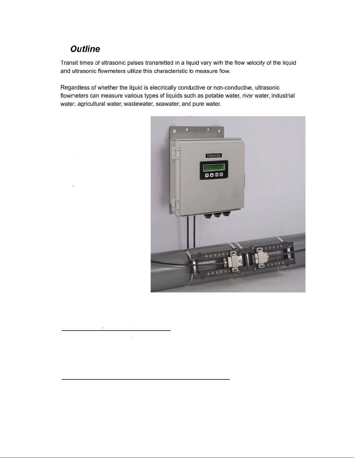
1) Tran
and
2) Reg
flow
wate
3)
Tran
the o
nece
flow
no p
4) Flow
over
+30
5) Econ
flow
(24”)
6) Easy
confi
grap
simpl
input
it times of
ltrasonic fl
rdless of w
eters can
, agricultur
ducers are
utside of th
sary to cut
or installati
essure loss
measurem
wide rang
/s.
omical mea
rom 25mm
can be obt
Operation
uration sof
ical user in
e and usef
all data.
ltrasonic p
wmeters ut
ether the li
easure va
l water, wa
clamped o
pipe so it i
pipes or st
n and ther
.
nts are po
e, -30m/s t
surements
(1”) to 600
ined.
hrough PC
ware. Thro
erface, it is
l for everyo
lses trans
ilize this ch
uid is elec
ious types
tewater, s
to
not
p
is
sible
f
m
gh
very
ne to
itted in a li
racteristic t
rically cond
f liquids su
awater, an
uid vary wi
o measure
ctive or no
h as potab
pure water
h the flow v
low.
n-conductiv
e water, riv
.
elocity of th
e, ultrasoni
r water, in
liquid
ustrial
2.
F
ature
1) Gra
Mou
para
2) Em
auto
A Tot
Thro
1 mi
hical PC c
gh EZ-wiz
ting positio
eters auto
rgency Re
ute interval
atically wit
l of 64000
nfigurati
rd, all requi
of transduc
atically.
undancy
for 1-mont
all events
points data
n ‘’EZ-wiz
ed paramet
ers will be c
ystem (Au
of data will
ata.
logging cap
rd’’
rs can be in
lculated by
tomatic Lo
be logged
ability.
put.
input
gging Syst
nternally a
em)
d
1
Page 3
3) Echo-wave monitor
Receiving echo will be indicated on the PC configuration software.
This feature helps to identify ideal mounting positions of transducers.
4) Variety I/O port
Analog output (Std.), Totalizing output (Std.), Digital port (Std.),
and Digital port / RS-485 MODBUS (Option) are available.
5) Extra A-IN available
By using optional card, 1 port for passive analog input (option)
can be available.
This information will be stored as internal logged data automatically.
6) Site Check mode
Any Error will be indicated on the LCD without PC or any software.
7) EZ-Translation
Any languages are configurable on the PC locally.
3. Configuration
Flowmeter components
Component Model Quantity Description
1. Main unit LF810 1 pc Flowmeter main unit
2. Tra ns duc e rs
3. Coaxial cables (*) RG-223/U 2 pcs
1MHz T r a ns d ucer
for 1” – 24” Pipe
2 pcs
Ultrasonic transmit and receiving
transducers and pipe-mounting fixtures
for transducer
Connection cable between converter
and transducers (includes 33ft.of cable)
(max. cable length: 30m)
2
Page 4
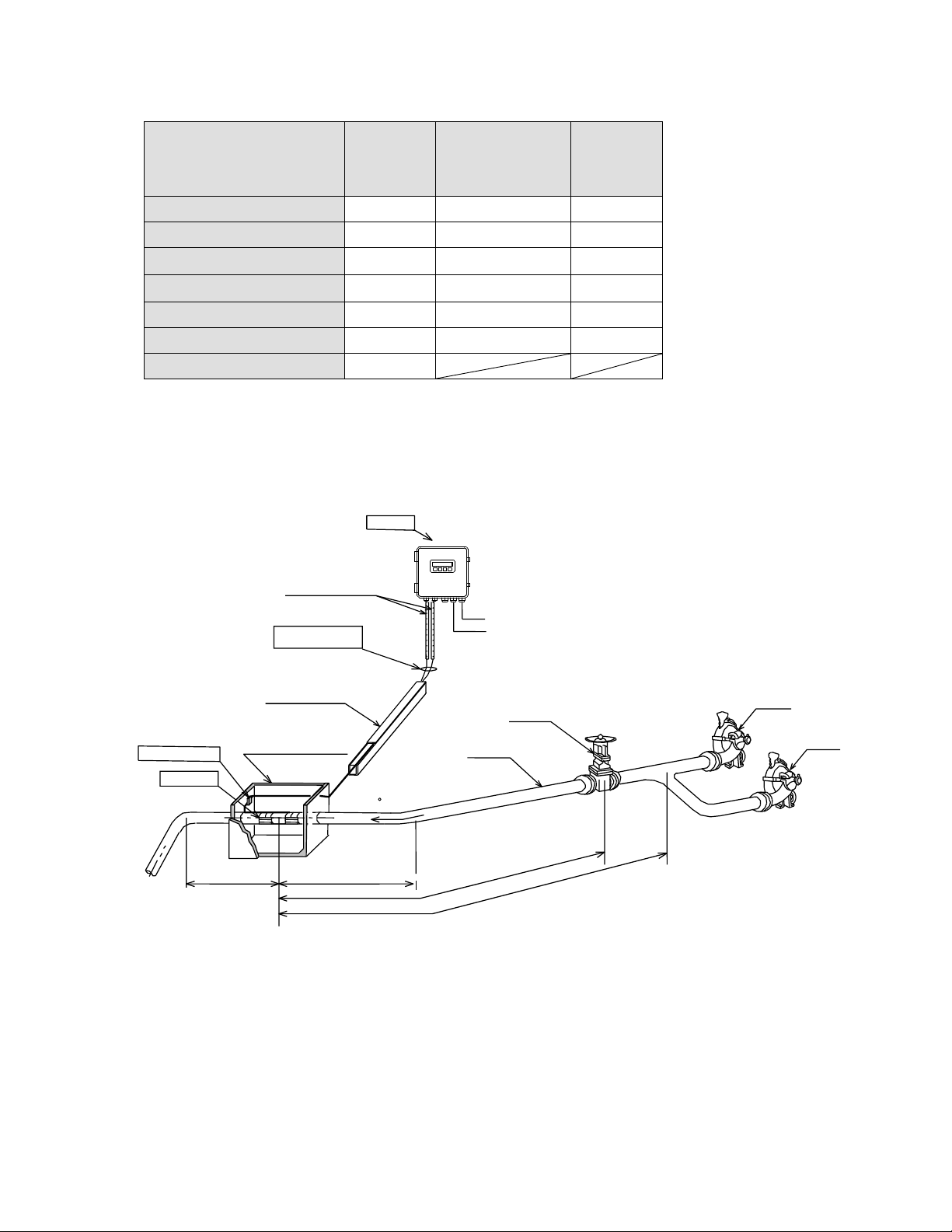
1MHz transducer components are as follows.
r
Components
Quantity
Material
Weight
(approx.)
1. Transducer 1pair (2pcs) Case : PBT (Plastic) 180g / 2pcs
2. Holder 2pcs PBT (Plastic) 160g / pc
3. Fastening Fixture 10pcs SUS304 20g / pc
4. Stainless Band 15 m SUS430 24g / m
5. Clamp 2sets SUS304 55g / set
6. Thumb Screw (for Z-method) 4pcs SUS303 16g / pc
7. Installation Outfit 1set
Main unit
Conduit pipe (
size
22)
Cable connection
Transduce
Flowmeter cabinet (Pit)
5D or more
Coaxial cable
(30m or less)
Cable trough
(90 bend
Flow
Enough length for fully developed
rotationally symmetrical flow profile required.
)
Power source
Output si gnal
Pipe
(inner diameter = D)
(Note)
Valv e
Pump outlet
(Note)
Note: Contact the manufacturer if a pump, valve, pipe with gradual width
increment, or merger pipe is installed at either the upstream or
downstream side.
Pump
Pump
3
Page 5
4. Specifications
4-1. Overall Specifications
Measurement Fluids Homogeneous and ultrasonically conductive fluids
(Clean water, waste water, industrial water, river water, sea
water, pure water, etc.)
Temperature range -4 to 140°F (-20 to 60°C)
Note:
1) above also applicable to ambient temperature
2) For main unit, 14 to 122°F (-10 to 50°C)
Turbidity 10000 mg/L or less
Note) No air bubbles
Pipes
Measurement
range
Number of
measurement
paths
Measurement
cycle
Measurement
Performance
Measurement
method
European
compliance
(CE marking)
Material Pipes made of materials that allow stable transmission of
ultrasonic waves, such as steel, stainless steel, cast iron,
ductile cast iron, PVC, FRPM, etc.
Note) Applicable pipe bores may vary depending on the pipe material
and condition.
Diameters 1” – 24” (DN25mm to DN600mm)
Lining None, tar epoxy, mortar, etc.
Note) Linings must be closely adhered to the base pipe.
Converted to flow velocity: -30 m/s to +30 m/s
1 measurement path
1 s
1”-1.75”
(DN 25 ~ 40mm)
2” – 3.5”
(DN 50 ~ 90mm)
4” – 10”
(DN 100 ~ 250mm)
12” – 24”
(DN 300 ~ 600mm)
Repeatability
±2.5%(*) of reading, however ±0.025(*) m/s for flow
velocities less than 1 m/s
(*) Depending on calibration
±2.0% of reading, however ±0.020 m/s for flow velocities
less than 1 m/s
±1.5% of reading, however ±0.015 m/s for flow velocities
less than 1 m/s
±1.0% of reading, however ±0.010 m/s for flow velocities
less than 1 m/s
±0.5%
Range ability 1 : 300
Note:
1) For volumetric flow rate.
2) Fully developed and rotationally symmetrical flow profile required.
3) Verified by manufacturer's conditions.
Ultrasonic pulse transit time difference method
Safety: IEC61010-1 2nd Edition
EMC: EN61326-1:2006 + EN61326-2-3:2006
4
Page 6
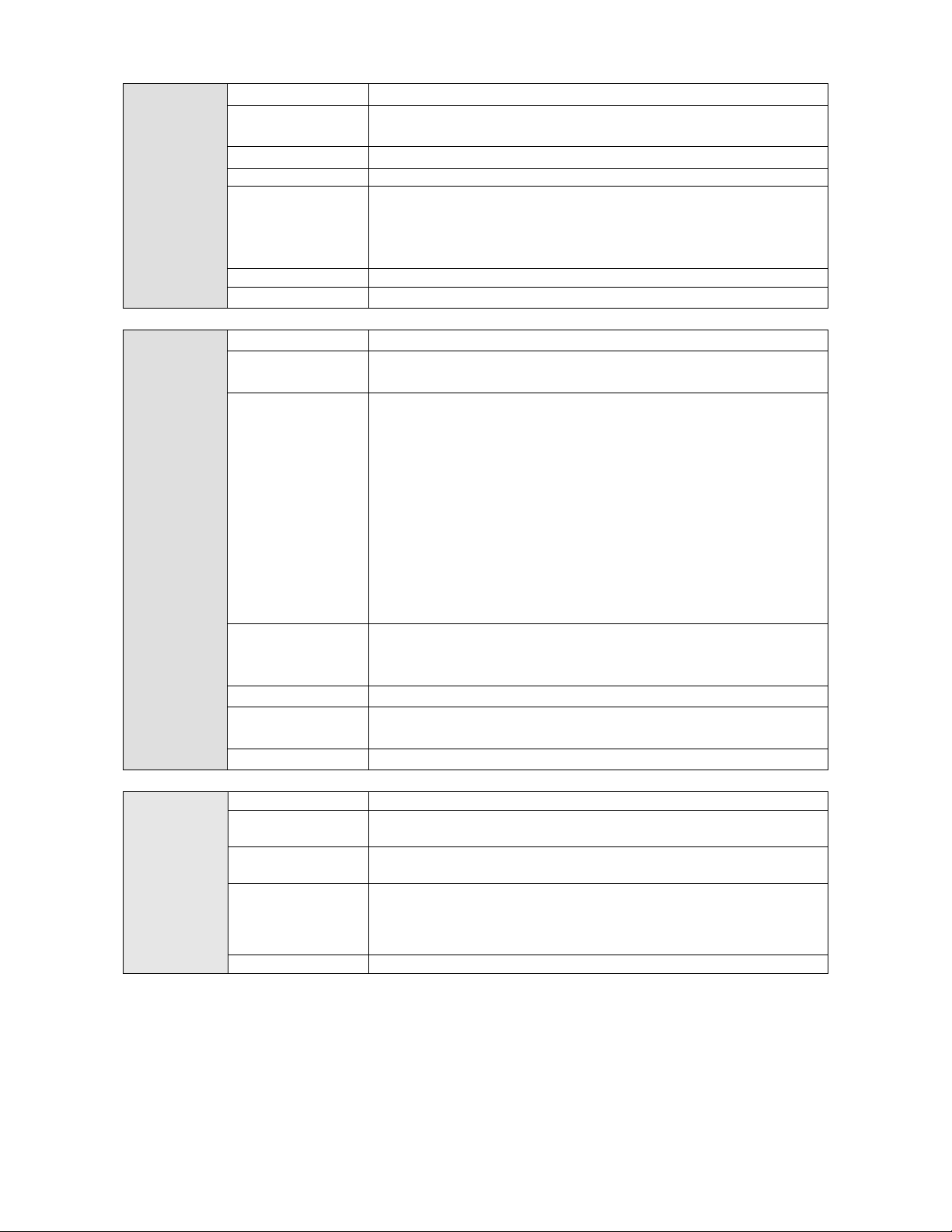
4-2. Main Unit
Analog
output
Contact
point output
USB
communication
Std / Option Standard
Number of
channels
1
Output contents Instantaneous flow rate
Output pattern Single system
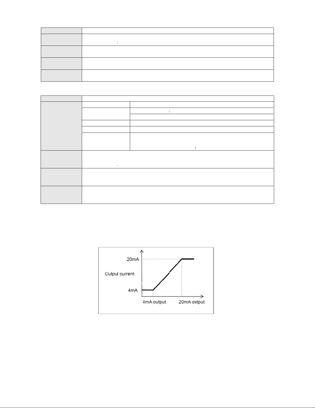
4 – 20mA, Burnout 20.8mA (when “no echo received” or during
Output format
“failure warning” output available)
Max. allowable load resistance 600ohm
Insulated outputs, 10-bit equivalent accuracy
Update cycle 125ms (8Hz)
Terminal panel Screw less Terminal (0.08~2.5mm2 cable applicable)
Std / Option Standard
Number of
channels
1
Selectable from:
1. Forward flow totalized pulse
2. Backward flow totalized pulse
3. No echo received warning (ROFF)
4. Equipment failure warning
Output
5. No echo received warning or Equipment failure
6. Hi-Limit alarm
7. Lo-Limit alarm
8. Forward flow identification
9. Always open
10. Always closed
Pulse width of contact is selectable from 1000,500,100 or 20ms.
Pulse Width
Note:
1) But not for both forward and backward.
Output format Photo coupler (insulated)
Contact point
capacity
DC48V, 0.4A
Terminal panel Screw less Terminal (0.08~2.5mm2 cable applicable)
Std / Option Standard
Number of
channels
USB Cable
length
1
Up to 3m
Flowmeter programming, measurement value display, received
Functions
signal waveform display, and log data readout using dedicated
software*1
*1 Compatible with Windows 7, Vista and XP
Connector USB-B terminal, hot plug possible
5
Page 7
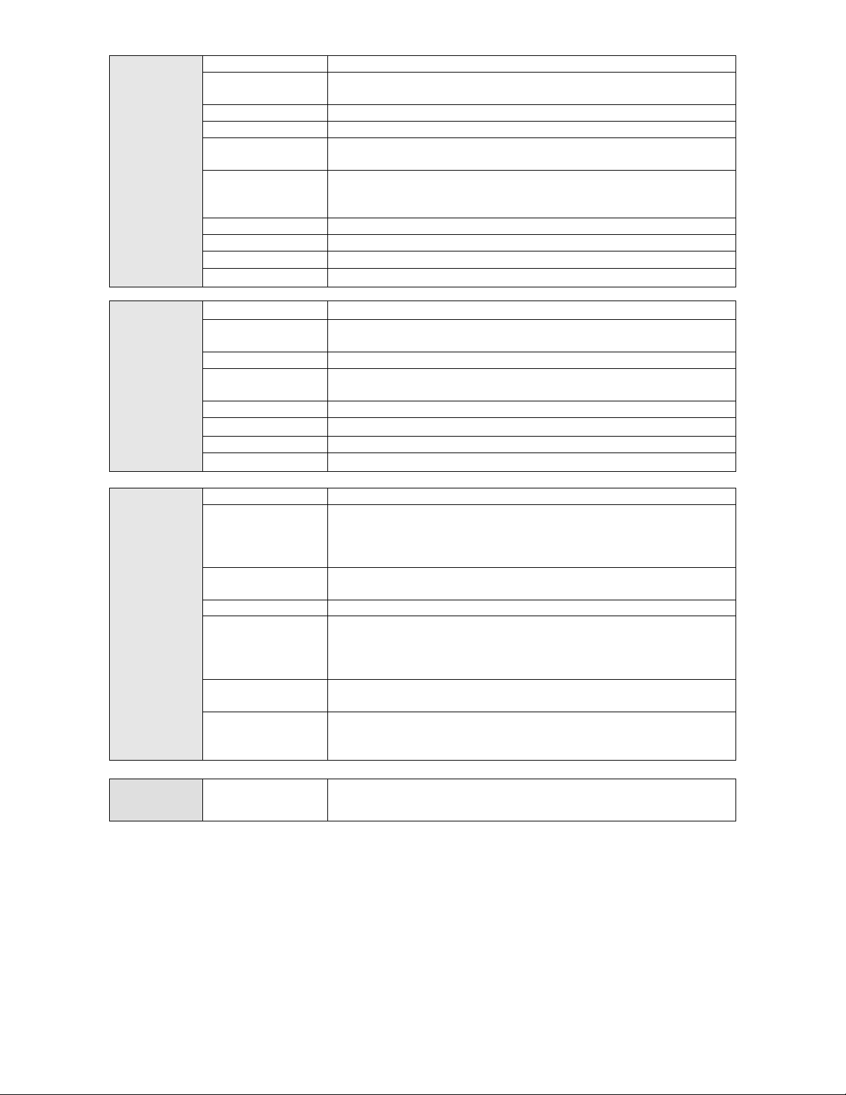
RS-485
*1
communication
Std / Option Option
Number of
channels
1
Output format RS-485 (insulated type)
Protocol MODBUS-RTU compatible
Transmission
Length
Up to 1km (depending on cable and communication speed)
Forward flow totalized value, backward flow totalized value,
Data
instantaneous flow rate, instantaneous flow velocity, equipment
status, etc.
Baud rate 4800, 9600, 19200, 38400 bps (Selectable)
Parity None, Even, Odd (Selectable)
Data bit length 8 bit /1 stop bit
Terminal panel
Screw less Terminal (0.08~2.5mm²)
Analog input Std / Option Option
Number of
channels
1
Output format Insulated inputs, passive method
Input range
4-20mA
Input resistance 300 Ohm or less
Accuracy 8-bit equivalent
Sampling cycle 1 s
Input contents Selectable from current ratio (%) or current value (mA)
Terminal panel
Screw less Terminal (0.08~2.5mm²)
Log function Std / Option Standard
Log contents: Date and time, instantaneous flow rate,
Contents
instantaneous flow velocity, forward flow totalized value,
backward flow totalized value, analog input value, measurement
status, error status
Number of
log entries
68000 entries
Log method Ring buffer method
Initial value: 60 s, setting range: 0 to 3600 s
Log cycle
1.5 months or more at a 60 s cycle (60 entries x 24 hours x 45
days = 64800 data)
1 year or more at a 600 s cycle
Data retrieval
USB communication using dedicated software “UFW Config”
or MODBUS communication (option)
Data is held for approximately 5 years in the power OFF status.
Data retention
The battery can be replaced.
*1 When the internal lithium battery is fully charged.
Data setting
Setting method
LCD 4-keys entry or USB communication setting through PC
with dedicated software “UFW Config”
6
Page 8
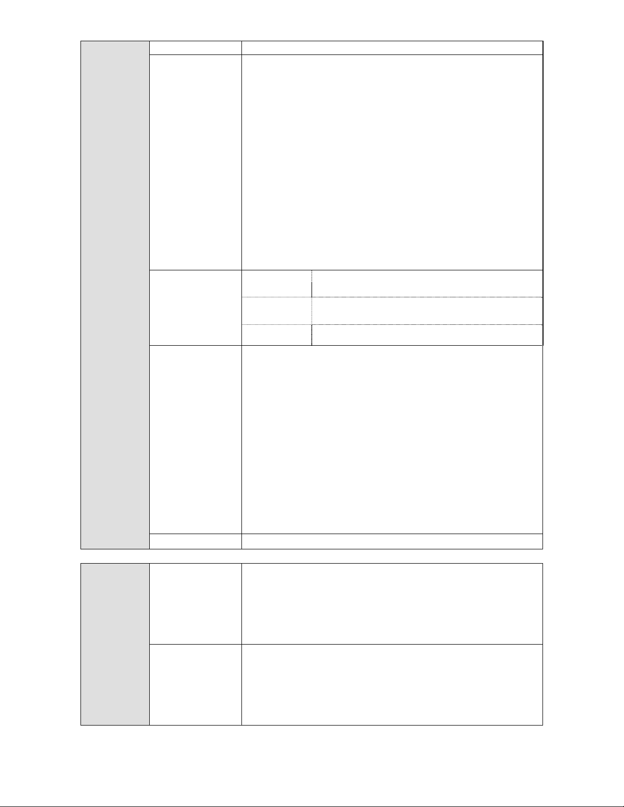
Display Display method LCD (16 character x 2 lines), with backlight
The following items displayed in the upper and lower lines on LCD
can be selected.
• Instantaneous flow rate and units
• Instantaneous flow velocity value and units
• Forward flow totalized value and units
• Backward flow totalized value and units
• Error code
Display content
• Status (Out of full scale, No receiving echo warning, Disturbance
detected, Signal Saturation, Check mode and
Low battery)
• Analog input value (*Option)
• ROFF counter value
• DIS. counter value
• Upside gain amplitude
• Downside gain amplitude
• Date & Time
Display digits
Instantaneous
flow rate :
Instantaneous
flow velocity :
Totalized flow : Totalized flow 8 digits including decimal point
Max. 7 digits including sign and decimal point
sign section 1 digit, integer section 2 digits
and decimal fraction 3 digits fixed
Units
Symbols are displayed at the right side of the LCD.
• “R”: No echo signal received. (upper line of the LCD)
• “D”: Disturbance detected. (upper line of the LCD)
• “S”: Receiving echo signal saturated. (upper line of the LCD)
• “C”: CHECK function is active. (upper line of the LCD)
• “B”: Low voltage of coin battery (lower line of the LCD)
Warnings
• “E”: Error occurred by equipment failure. (upper line of the LCD)
• “F.S.”: Full Scale (Upper line of the LCD)
(During exceeding the maximum flow rate of measurement range,
indication would be alternated flickering “the maximum value of
measurement range” and “F.S." symbol at the upper & left side of LCD.)
Note:
1) The priority between the above symbols (indicated at the same position) as follows.
E > C > R > D > S
Error code “ERR-01” to “ERR-63” displayed during equipment failure.
• Multiplier
-6
), m (x10-3), x1, k (x103), M (x106)
3
L/, m
/, g/, t/, ft3/, bbl/, gal/, acf/
Flow rate units
u (x10
• Flow volume units
• Flow time units
/s, /min, /h, /D
• Multiplier
-6
), m (x10-3), x1, k (x103), M (x106)
Totalizing units
u (x10
• Decimal point position
******* (x1), ******.* (x0.1), *****.** (x0.01)
• Units
3
L, m
, g, t, ft3, bbl, gal, acf
7
Page 9
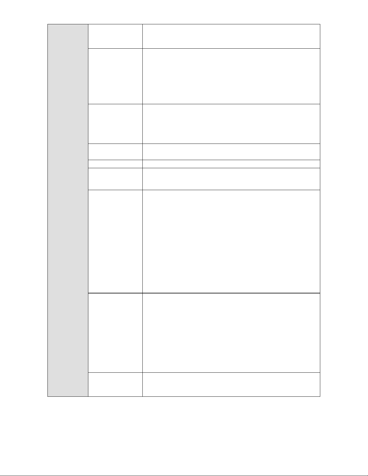
Function
Cuts (Zeros) flow when flow falls below prescribed instantaneous
Low flow cut
flow rate. Used in order to avoid output of flow values other than 0
when measurement value during still flow becomes irratic.
If measurement cannot be made when no echo is received
No Echo receiving
warning
continuously over the setting time
changed to
- Display "R" on LCD.
- Selected output operation (Analog & LCD)
(determined transition time), status is
- Contact output of warning if set.
- Count up as history on ROFF counter
Check whether processing values are measured properly or not
Disturbance
detection
and if determined to be disturbed conditions then measuring
values are eliminated.
- Display ”D” on the display
- Count up as history on DIS. counter
Zero point
correction
Zero point can be independently compensated (shifted) for flow
rate.
Span correction Slope of span line can be corrected for flow rate.
Rapid flow rate changes would be smoother by this filter.
Output Filter
Note: This value is meaning the time until measuring flow rate reaches 90%
by step-up increment.
If failure is diagnosed on following items, transitions to be
selected status.
Diagnostic checks:
1) Transmitting and receiving circuit
2) CPU
Self-diagnostics
and
failure processing
3) DSP
4) Internal clock
5) Memory Area (for setting parameter)
6) Parameters
- Selected analog output transition status as follows.
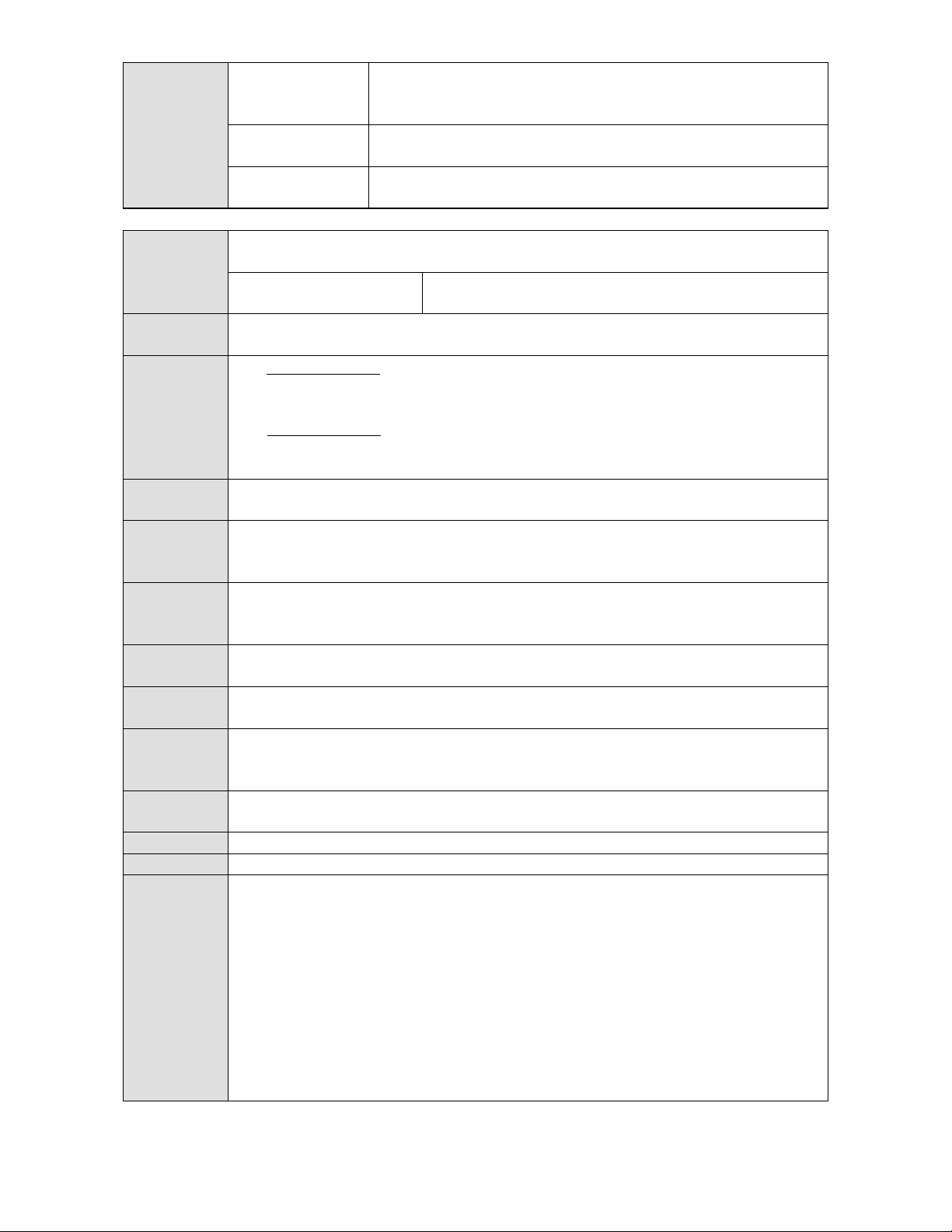
0% (4mA), hold, 100% (20mA), burnout (20.8mA)
- Display "ERR-**" on LCD. (** is error number.)
- Contact output of warning if set.
Totalized flow values and all setting parameters are retained in
memory with lithium battery even if power failure.
Note:
Data retention
1) Setting Parameters are retained in nonvolatile memory.
2) Totalized flow value, Logged data and ROFF/DIS. counters are retained in
memory which held by the battery.
3) Data retained in memory which held by the battery clears if battery
removed without power supply.
4) 5 year life at room temperature.
5) No battery recharging function.
- Simulated flow check mode
Check Function
- Analog output check mode
- Totalized pulse output check mode
8
Page 10
Function
(cont.)
Automatic gain
control
(AGC Function)
Totalized value
preset
Error historic
counter
Receiver gain is automatically adjusted to the optimum level in
response to changes in receiver sensitivity during measurement.
Totalized values can be freely preset.
Preset Range: 0 to 99999999
Count "No Echo receiving warning" & "Disturbance detection"
when it occurred.
Power
supply
Power
consumption
AC100 to 230V +/-10% (50/60 Hz ±2Hz)
Option: DC24V±20% (This option must be pre-selected.)
Momentary outage
AC input: 20ms
DC input: 0ms
AC100V: 19VA / AC200V: 23VA
DC24V: 9W (Option)
Fuse AC: IEC 60127-2 SS5
Cartridge fuse-links, φ5.2x20 mm, Rating 2A/250V, Time-lag
and High Breaking Capacity (1500A)
DC: IEC 60127-2 SS5
Cartridge fuse-links, φ5.2x20 mm, Rating 4A/250V, Time-lag
and High Breaking Capacity (1500A)
Rush
Current
Less than 15A at AC100V / Less than 25A at AC200V
Less than 15A at DC24V (Option)
Operating
temperature
14 to 122°F (-10 to +50°C)
range
Storage
temperature
-4 to 140°F (-20 to +60°C)
range
Operating
humidity range
Main unit
construction
Wiring
Connection
port
Case
material
Less than 90% RH, non-condensation
Protection Degree IP65 (IEC 60529)
I/O and power ports: PG13.5 x 3, applicable cable diameter 7 to 12.5 mm
Sensor ports: PG9 x 2, applicable cable diameter 4.5 to 8 mm
Other: USB-B female type for USB communication x 1
ABS (Color: White gray)
Weight Approximately 5 lbs. (2.1 kg)
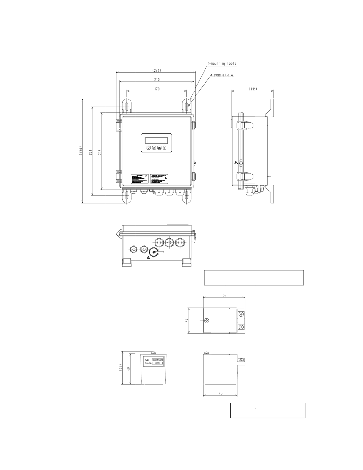
Dimensions 210mm (W) x 210mm (H) x 100mm (D), not including protrusions
EMC Directive 2004/108/EC
Harmonized Standard / EN61326-1:2006 + EN 61326-2-3:2006
Separation into group / Group I
Division into classes / Class A
European
Compliance
(CE marking)
Location intended for use / In industrial locations
Low Voltage Directive 2006/95/EC
Harmonized Standard / EN61010-1 2nd Edition
Over voltage category II
Pollution degree II
Altitude up to 2000m
9
Page 11
4-3. Tran
s
e
u
n
o
c
b
n
2
n
2
c
s
l
t
6IP6
G
s
s
r
t
rCon
a
g
e
c
p
0
t
e
n
n
4
m
f
n
i
w
a
L
-
P
nAWG
d
n
s
c
U
C
a
t
t
c
c
n
t
m
o
w
e
r
w
m
o
F
o
t
Transduc
Te mp e ra t
range
Protectio
class
Compatib
cable
Maximum
length
4-4. Opti
IP67 dete
Power ca
(*1)
Mounting
Expansio
board
AIN-10 (*
Expansio
board
485-20 (*
(*1)Power
(*2)Expan
ducers
SE
re
-4
IP
le
R
cable
30
nal part
tor Shi
le St'
Mo
Pa
Ma
De
plate Fo
Mo
)
)
able is sp
ion boards
An
Di
Ins
104720T
o 140°F (-2
5 (When fill
7 as an opt
-223/U
m
pped from t
/option
del name
t number
nufacturer
ails
wall moun
sist of:
unting plat
log input: I
ital commu
ulated RScified to co
an be mou
to 60°C)
ed with resi
ion (Resin-f
he factory
Prep
OLF
multi
1006
LAP
3 co
Nom
ing or stan
, U bolt, Wi
sulated pa
ication fun
85, MODB
ply with E
nted simult
by the ins
lled produc
ith a 30 m
red by use
EX Classi
conductor,
0
KABEL
ductors
16, 1.5 mm
nal outer di
ard pipe (D
g nut, Spri
sive input
tions
S-RTU co
directive.
neously.
aller)
, shipped
able conn
100
flexible po
2
ameter 8.1
N50mm) m
g washer,
ype
patible
ith cable c
cted
er and con
m
unting (Fig
lat washer,
nnected)
rol cable
. 1-2-3-3)
screw M4.
5. Ana
10
og out
ut pro
iles
Fl
w Rate
Page 12
6. Transducer installation
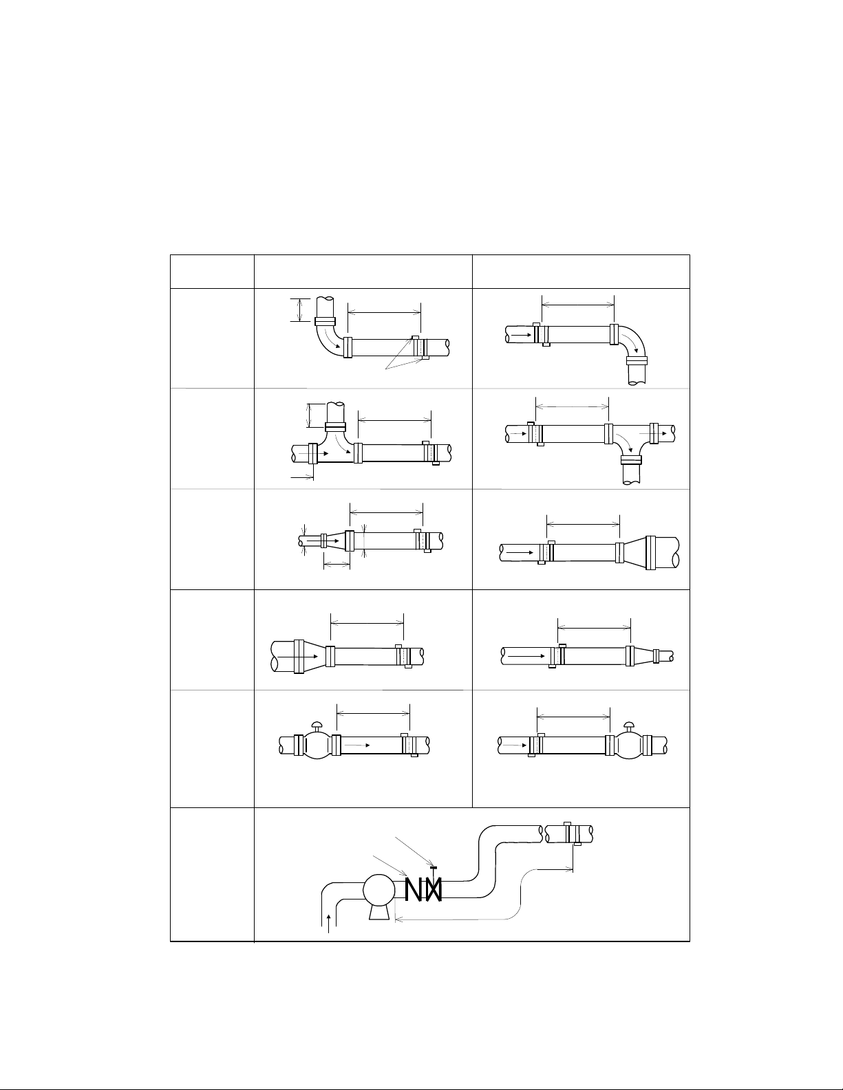
- To minimize measurement errors arising from flow profile, a straight pipe run is necessary for
transducer installation.
- Liquid should fill the pipes completely and transducers should be installed in locations which
have no air bubbles.
- For measurements in underground piping, the usual means is to locate the flowmeter in a pit to
facilitate transducer installation, maintenance, and testing.
Structural
condition
90°bend
T shape joint
Increasing
Diameter
Reducing
Diameter
Control
Valves
Pump
Upstream straight pipe length Downstream straight pipe length
10D
or
more
10D
or more
10D
0.5D
1.5D
Flow Control at upper side
Checkvalve
L≧10D
Probe
L
L ≧30D
D
≧10D
L
L≧30D
Stop Valve
P
≧50D
[Refer to JEMIS 032-1987 ]
L≧5D
L ≧ 10D
L ≧ 5D
L ≧ 5D
≧ 10D
L
Flow Control at lower side
≧ 50D
L
11
D : Pipe Diameter
Page 13
m
M
D
T
7.Di
ensions
12
ain Unit
imension
ransducer
Page 14
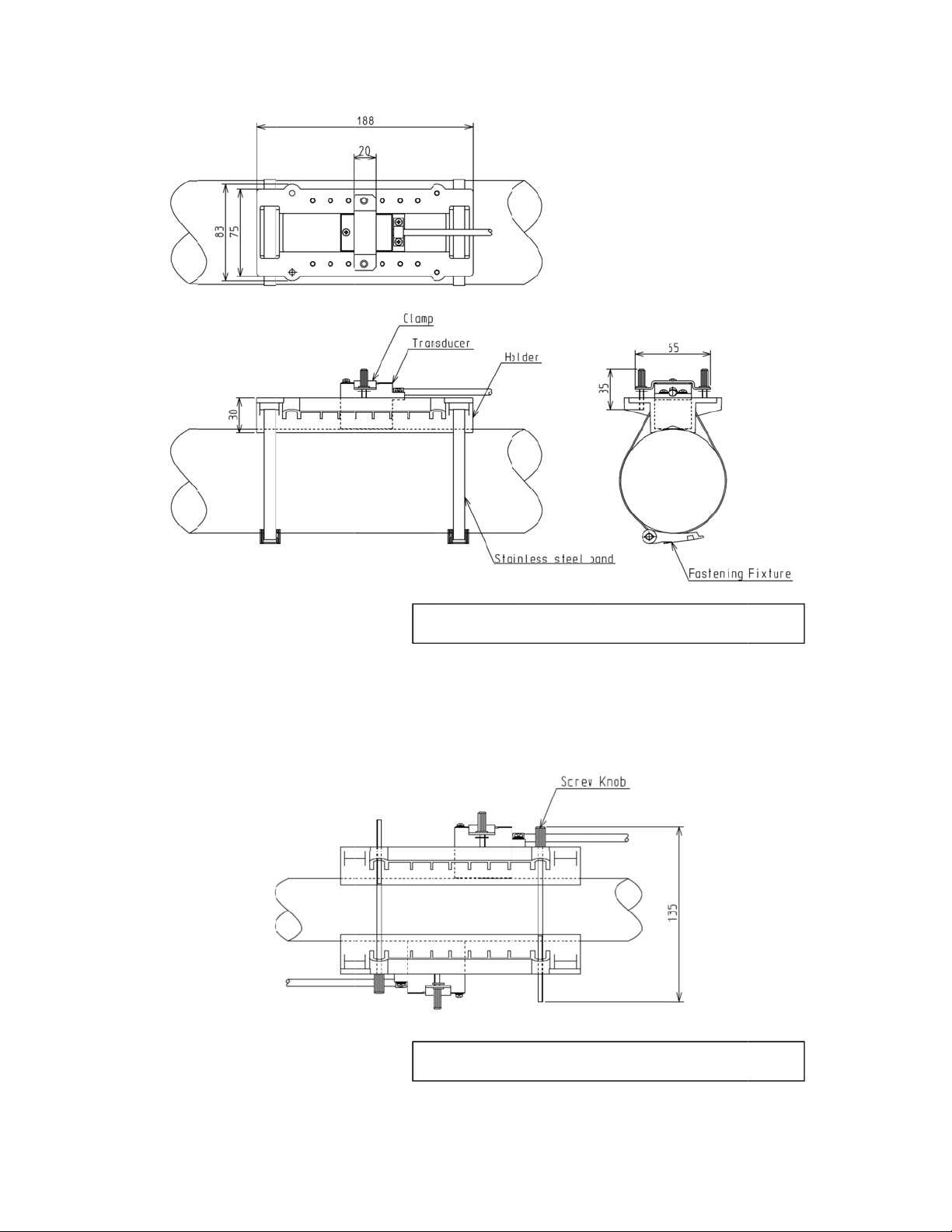
u
g
r
a
Mo
Mountin
nting Fixt
Fixture fo
ure for Tr
Transduc
nsducer
er (Z method)
13
Page 15
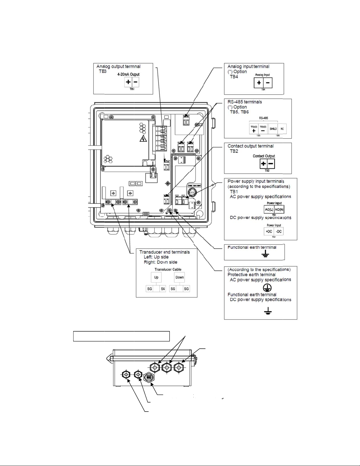
i
t
b
o
c
o
i
o
e
a
b
C
c
(
d
j
p
c
p
8. W
8-1. Ou
8-2. Ca
ring C
put conne
le entry p
Bottom v
nnecti
tion
rt
ew of main n unit cas
C
Ca
USB-B
ble gland
le gland
able glan
Cab
onnector
Down-sid
Up-side tr
s (I/O)
le gland (
ack
e transdu
ansducer)
ower sup
er)
ly)
14
Page 16
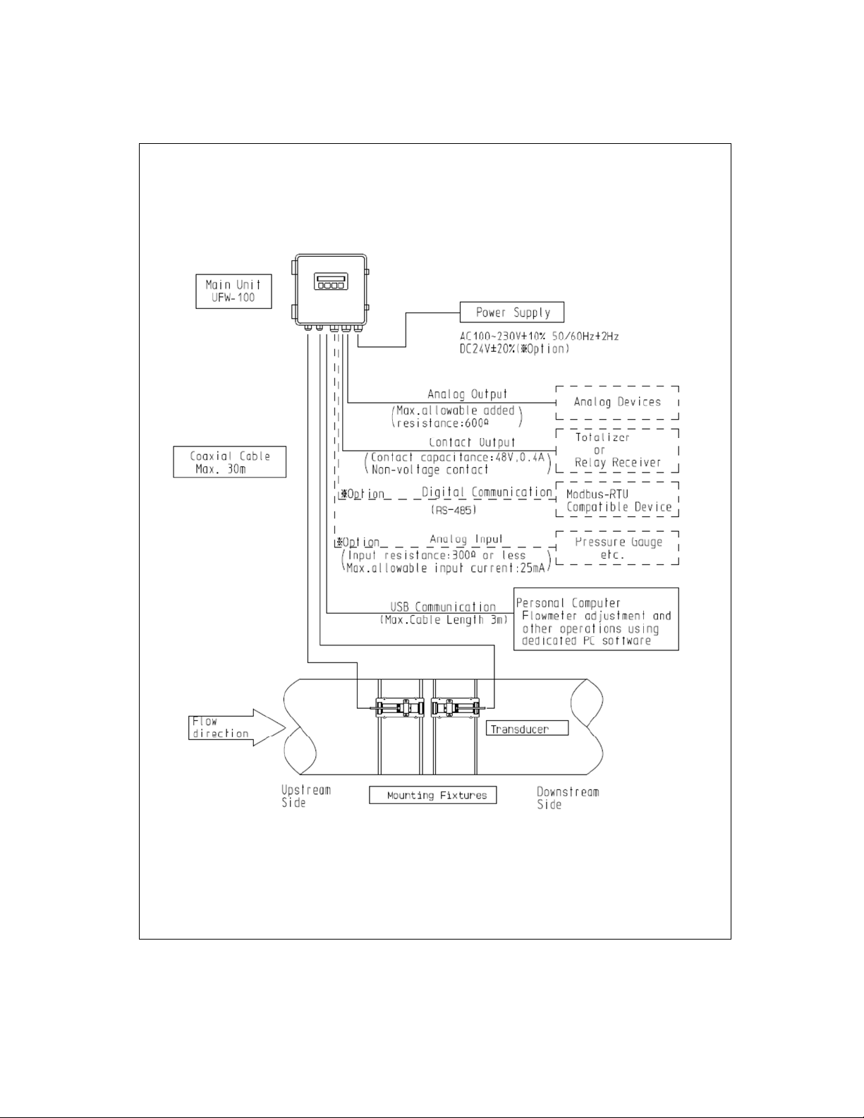
9. System Wiring Connection
15
Page 17
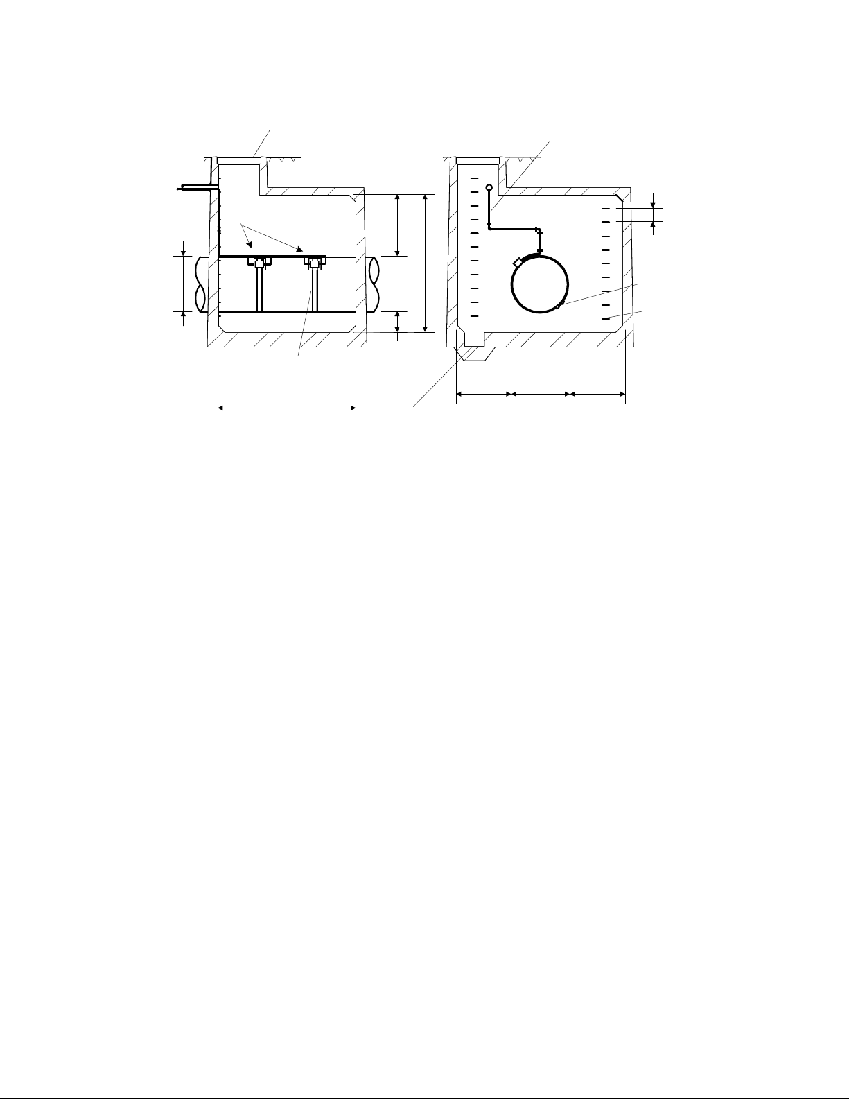
10. Building a flowmeter pit
Manhole
G.L. G.L.
Coaxial cable
Flowmeter Pit
300mm
Fastening
Fixture
Foot St ep
Pipe Dia (d)>600mm >600mm
Transducer
s
>300mm
>2000mm
Pipe Dia. (d)
Stain less Steel Band
V path method: d+1200mm
Z path method: d/2+1200mm
>300mm
Water drainage 500×500×d300
- In principle, when measurement is of underground pipe, it is suggested to prepare dedicated
flowmeter pit.
- It is not necessary to prepare a flowmeter pit in the case of indoor or outdoor piping, but proper footing
should be planned for transducer mounting and equipment adjustments where the pipe is located
high off the floor or when pipe diameter is large.
Building a flowmeter pit
1. Select pit site (taking into consideration the following points)
1) Straight section of pipe is required for installation of transducers as explained under Part 5.
2) Consult manufacturer if an adjustable valve or pump is used.
3) To prevent noise interference or signal attenuation, coaxial cable used transducers and main
unit should be less than 30m.
2. Size and construction of flowmeter pit
1) Using above schematic as reference, determine size of flowmeter pit based on actual piping
position and conditions. Height of pit should allow person to stand while working.
2) Implement countermeasures for floods such as drainage gutters, etc. (Install water pump where
water is liable to accumulate or flood.)
3) Consult Manufacturer for other specific conditions. (Above dimensions are ideal and not the
minimum required.)
Transducer installation
1. Strip paint/coating from piping surfaces at transducer mounting locations and fix transducers
on piping using the accessory mounting fixtures. When mounting transducers according to the
“V” method, the distance separating the transducers should be about the diameter of the pipe.
If the “Z” method is used, the distance should be one half of the diameter.
2. After installing and adjusting the transducers, remove transducer mountings, and coat pipe
surface with anti-rust paint.
16
Page 18
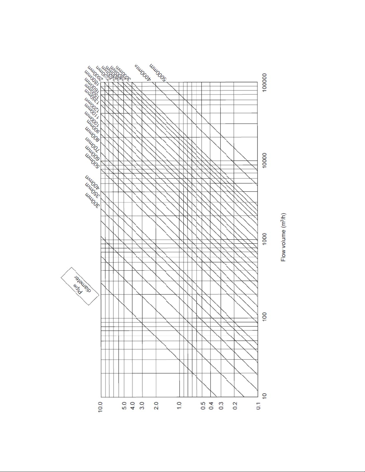
p
w
x
n
11. A
Flo
pendi
Volume a
d Average Flow Velocity
Average Flow Velocity (m/s)
17
Page 19
r
f
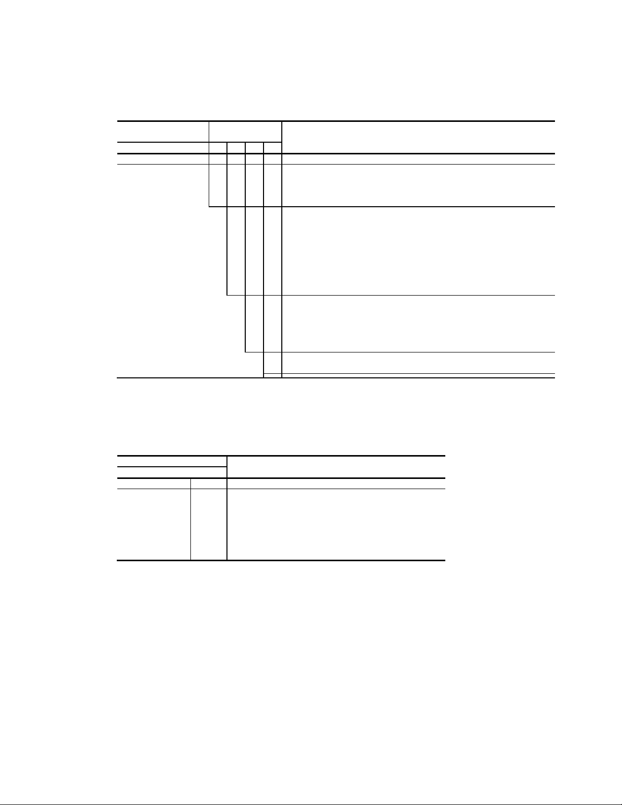
Specification Code
Model number table
Model number
1 2 3 4 5 6 7 8 9
L F 8 1 0
Specification
code
A
D
A
B
Contents
ULTRASONIC FLOWMETER
supply
Powe
100-230Vac,50/60Hz
24Vdc±20%
Transducers Type
Standard (requires connecting to cables)
Factory epoxy potting (Meets IP67, includes connecting cables
to transducers only)
Note:
・Coaxial cables
※
1 All Meters are shipped from the factory with two (2) 10 m cables.
All I/O options must be selected at time of ordering.
All units come with stainless steel mounting plate.
Code
1 2 3
C C L
4 5 6
0
0
0
0
5
1
0
1
5
2
0
2
5
3
0
0
1
2
3
Length ※1
Without cable
5m
10m
15m
20m
25m
30m
I/O card
No need
Rs-485 Modbus Communication Card
Analog Input Card(1ch)
Both of RS-485 Modbus and Analog Input
Mounting
Mounting plate (wall, surface or stand pipe)
B
or Main unit
Contents
18
Page 20

INDUSTRIAL DIVISION
13131 WEST LITTLE YORK ROAD HOUSTON, TX 77041
PHONE: (713) 466-0277 (800) 231-1412
FACSIMILE: (713)896-5225
19
 Loading...