

Toshiba LF600F User Manual

TOSHIBA
,6,F.8A0,8.6,9,
ELECTROMAGNETIC FLOWMETER
MODEL LF600F and LF602F
INSTRUCTION MANUAL
TOSHIBA CORPORATION
NOTES
Before using the equipment, please read this manual carefully and understand the con
tents, and then use the equipment correctly.
• NEVER attempt to operate the equipment in any ways that are not described in this
instruction manual.
• After reading this manual, store it with care in a place where it can be referred to
whenever needed.
• Please be sure that this manual is delivered to the personnel who will use this product.

TOSHIBA
We thank you very much for your purchase of our LF600F series electromagnetic flow
meter converter.
Integral type converter LF600F
Separate type converter LF602F
This instruction manual describes the notes on using an electromagnetic flowmeter con
verter, installation, configuration and maintenance. It is intended for the personnel in charge
of installation, operation and maintenance.
To use this product properly and safely, read this manual (6F8A0869) carefully before using
this product. After reading this manual, store it in a place where it can be referred to
whenever needed.
About a PROFIBUS communication function, please read instruction manual 6F8A0873.
This manual uses the following markers to identify the integral type or separate type when it
describes items specific to the integrated type or separate type. Items without this marker are
common items to the integral type and separate type.
6F8A0869
NOTICE
Integral type converter LF600F:
Separate type converter LF602F:
Toshiba LF60*F electromagnetic flowmeter converters can be used in combination with vari
ous types of electromagnetic flowmeter detectors (LF414, LF434 and LF494).
For the notes on usage, piping, installation, configuration and maintenance of the com
bined detector, check the model number of the combined detector and read the instruc
tion manual of the relevant detector.
About Safety Precautions
Read the Safety Precautions described at the front carefully and understand the contents
before using this product.
The “Safely symbols” used in the “Safety Precautions” are shown in a location such as
in the margin to the left of the corresponding commentary in the main text.
NOTES
1. The reproduction of the contents of this Manual in any form, whether wholly or in
part, is not permitted without explicit prior consent and approval.
2. The information contained in this Manual is subject to change or review without
prior notice.
3. Be sure to follow all safety, operating and handling precautions described in this
Manual and the regulations in force in the country in which this product is to be
used.
LF600F
□
LF602F
_____________
10th Edition
First Edition
June, 2007
September, 2005
- 1 -

TOSHIBA
SAFETY PRECAUTIONS
Safety signs and labels affixed to the product and/or described in this manual give important
information for using the product safely. They help prevent damage to property and obviate
hazards for persons using the product.
Make yourself familiar with signal words and symbols used for safety signs and labels. Then
read the safety precautions that follow to prevent an accident involving personal injury, death or
damage to property.
Explanation of signal words
The signal word or words are used to designate a degree or level of hazard seriousness.
Indicates a potentially hazardous situation, which, if not avoided,
A WARNING
A CAUTION
Notes:
1 “Series injury” refers to an injury such as loss of sight, physical damage, burns (high
could result in death or serious injury.
Indicates a potentially hazardous situation, which, if not avoided,
may result in minor to moderate injuries or in property damage.
¡6jFi8|A0|8|6j9j
temperature or low temperature) electric shock, bone fracture and poisoning and the
after effect of the injury remains or the injury requires hospitalization or long periods
of outpatient treatment.
2 “Minor to moderate injuries” refers to burns, electric shocks, and so on, that do not oblige
the injured person to be hospitalized or go to a hospital for a long period of time for
medical treatment. “Property damage” includes all kinds of damage to property,
equipment or materials.
Safety symbols
The following symbols are used in safety signs and labels affixed to a product and/or in the
Indicates an action that is prohibited. Simply DON’T do this action.
0
•
A
The prohibited action is indicated by a picture or text inside or next to the circle
Indicates an action that is mandatory. DO this action.
The mandatory action is indicated by a picture or text inside or next to the circle.
Indicates a potential hazard. The potentially hazardous situation is
indicated by a picture or text inside or next to the triangle.
Color explanation
WARNING A Background color: Yellow and Red, Border: Black, Picture display: Black
CAUTION A Background color: Yellow, Border: Black, Picture display: Black
- 2 -

TOSHIBA
SAFETY PRECAUTIONS (continued)
Safety Precautions for Hazardous Locations
A WARNING
Do not disconnect while circuit is live unless location is known to be nonhazardous.
,6,F,8,A0,8,6,9,
0
DON’T
Do not modify or disassemble the enclosure.
DON’T
Do not use parts of other products.
0
DON’T
Do not live circuits While assembly of all components is not over.
0
DON’T
Install per the National Electrical Code for the US (NEC, ANSI/NEPA 70) and the
Canadian Electrical code for Canada (CEC, CAN/CSA-C22.1) and the drawing
3S8A2532y3S8A2533 (Refer to Appendix 2.).
Live part of electric circuit or a high temperature department can cause explosion.
Strength degradation and defects of enclosure can cause explosion.
Protective performance degradation for hazardous location can cause explosion.
Protective performance degradation for hazardous location can cause explosion.
O
DO
Unsuitable conduit connections for hazardous location can cause explosion.
- 3 -

TOSHIBA
SAFETY PRECAUTIONS (continued)
Safety Precautions for Installation and Wiring
A CAUTION
■ Install a switch and fuse to isolate the
LF600F and LF602F from mains power.
Power supply from mains power
can cause electric shock or
PQ circuit break-down.
■ Use an appropriate device to carry and install
the LF600F and LF602F.
^E^P injury, or malfunction of or damage
00 to the product, can be caused.
6iF,8iA0i8i6,9i
If this product falls to the ground,
■ Turn off mains power before
conducting wiring work.
Wiring while power is applied
can cause electric shock.
DO
■ Turn off mains power before working on
pipes.
Working on pipes while power
^E^P is applied can cause
00 electric shock.
■ Do not conduct wiring work with bare
hands.
Remaining electric charge
i even if power is turned off can
Vi—^ still cause electric shock.
DON’T
■ Do not work on piping and wiring with wet
hands.
Wet hands may result in
1 electric shock.
■ Do not modify or disassemble the LF600F and
LF602F unnecessarily.
Modifying or disassembling this
V IX/ product can cause
electric shock, malfunction of or
DON T damage to this product.
■ Ground the LF600F and LF602F independently
from power equipment.
(100 ohm or less ground resistance)
Operating this product
without grounding can cause
00 electric shock or malfunction.
Use crimped terminal lugs for the terminal
board and GND terminal.
Loose connections can cause
^E^P electric shock, fire from
excessive current or system
malfunction.
DON’T
j. The label shown left is placed near the terminal board for
AV power supply on the converter.
/H \ (A black border and symbol on yellow triangle)
Be alert to electric shock.
- 4 -

TOSHIBA
SAFETY PRECAUTIONS (continued)
Safety Precautions for Maintenance and Inspection
A CAUTION
6,F,8,A0i8,6,9,
■ Do not conduct wiring work with wet hands.
Wet hands may result in
electric shock.
DON’T
■ Do not use a fuse other than the one
specifled.
Using a fuse other than the one
specified can cause system
DON’T failure, damage or malfunction.
Use a rated fuse as follows:
Fuse rating:
®0.8A(T)/250V for 100 to 240Vac or 1 lOVdc
02A/15OV for24Vdc
Dimensions: Diameter 5 mm x 20 mm
Melting time characteristic: ©Time Lag
(2)Medium-Arcing (Normal blow)
Usage limitation
■ Do not conduct wiring work when power is
applied.
Wiring while power is applied can
cause electric shock.
DON’T
■ Do not touch the LF600F main body when
high temperature fluid is being measured.
The fluid raises the main body
1 temperature and can cause burns
DON’T when touched.
The label shown left is placed near
the terminal board for power input.
/U\ (A black border and symbol on
i \ yellow triangle)
Be alert to electric shock.
This product is not manufactured for applying to a system requiring safety directly involved
human life as follows. Please contact you're nearest Toshiba reprehensive if there is a possibility
of using this product for such use.
- Main control systems of nuclear power plants, safety protection systems in nuclear
facilities or other important systems requiring safety
- Medical control systems relating to life support
Warranty and Limitation of Liability
Toshiba does not accept liability for any damage or loss, material or personal, caused as a direct
or indirect result of the operation of this product in connection with, or due to, the occurrence of
any event of force majored (including fire or earthquake) or the misuse of this product, whether
intentional or accidental.
- 5 -

TOSHIBA i6|F|8|A;0|8i6i9i
Handling Precautions
To obtain the optimum performance from the LF600F and LF602F converter for years
continuous operation, observe the following precautions._______________________________
(1) Do not store or install the flowmeter in:
• places where there is direct sunlight.
• places where there is snow and ice
Infrared switches may not function correctly.
• places where excessive vibration or mechanical shock occurs.
• places where high temperature or high humidity conditions obtain.
• places where corrosive atmospheres obtain.
• places submerged under water.
• place where there is slop floor. To put the flowmeter temporarily on the floor, place it
carefully with something, such as stopper, to support it so that the flowmeter will
not topple over.
• Places where there is following factors.
♦ Factors to impede infrared switch to operate properly
• Intense light such as direct sunlight and reflected sunlight by window glass or metal plate
• Place where brightness changes always such as ON/OFF of lighting
• Dense smoke or steam near the control panel
• Those attached on the control panel such as rain (dew drop), snow, ice, mud and oil, and
haze due to their attachment
• Light reflecting object near the control panel, or reflecting object such as metal plate placed
opposing to the control panel
When any of above factors is considered, take a measure for the proper operation of
infrared switch such as to place a cover or to secure a space for at least a person to stand in
front of the control panel.
of
When unable to avoid above factors, operate the EMF converter removing the factor by
covering the control panel by hand so that light does not shine on it, by cleaning those
attached on the control panel, or by standing in-between the reflecting object and the
control panel to block the light.
(2) Wire cables correctly and securely.
Be sure to ground at the converter side (grounding resistance 100П or less).
Avoid a common ground used with other equipment where earth current may flow. An
independent ground is preferable
(3) Select cable paths away from electrical equipment (motors, transformers, or radio
transmitters), which causes electromagnetic or electrostatic interference.
(4) The cable glands is not provided in the conduit port of this apparatus.
Because I/2-14NPT screw holes are processed to this place, please prepare yourself for the
cable glands which could be used in Division2 hazardous locations.
The cable lead-in section must be tightened securely to keep air tightness.
- 6 -

TOSHIBA
Handling Precautions (continued)
(5) If the inside of the converter or cable terminals are wetted or humidified, it may cause
insulation deterioration, which can result in fault or noise occurrence. So do not conduct
wiring in the open air on rainy days.
Also, be careful not to wet down the converter even in the case of indoor wiring, and
complete wiring work in a short period of time.
(6) Observe the following precautions when you open the converter housing cover:
• Do not open the cover in the open air unprotected against rain or wind. This can
cause electric shock or cause damage to the flowmeter electronics.
• Do not open the cover under high ambient temperature or high humidity
conditions or in corrosive atmospheres. This can cause deterioration of system
accuracy or cause damage to the flowmeter electronics.
(7) Since a varistor is built in converter, do not conduct a withstand voltage test for the
converter.
In addition, the voltage for checking the insulation of the converter must be 250VDC
or lower.
,6,F,8,A0,8|6|9i
(8) This product may cause interference to radio and television sets if they are used near
the installation site. Use metal conduits etc. for cables to prevent this interference.
(9) Radio transmitters such as transceivers or cellular phones may cause interference to the
flowmeter if they are used near the installation site. Observe the following precautions
when using them:
• Close a transmitter cover before using a transceiver.
• Do not use a transceiver whose output power is more than 5 W.
• Move the antenna of a transceiver or a cellular phone at least 50 cm away from the
flowmeter and signal cables when using it.
• Do not use a radio transmitter or a cellular phone near the flowmeter while it is
operating online. The transmitter or cellular phone’s output impulse noise may interfere
with the flowmeter.
• Do not install a radio transmitter antenna near the flowmeter and signal cables.
(10) For reasons of flowmeter failure, inappropriate parameters, unsuitable cable
connections or poor installation conditions, the flowmeter may not operate properly.
To prevent any of these problems causing a system failure, it is recommended that
you have preventive measures designed and installed on the flowmeter signal
receiving side.
(11) For piping and installation of the combined detector, check the model number of
detector and read the instruction manual of the relevant detector.
We assume no responsibility for nonconformity caused by violation of precautions described
in this manual or used in violation of the installation method and the operation method
stipulated in a relevant ordinance or other regulations.
- 7 -

TOSHIBA
,6,F,8,A;0|8,6,9,
Table of Contents
1. Product Inspection and Storage........................................................................................................................11
1.1 Product Inspection................................................................................................................................... 11
1.2 Storage.......................................................................................................................................................11
2. Overview............................................................................................................................................................. 12
3. Names of Parts.................................................................................................................................................... 13
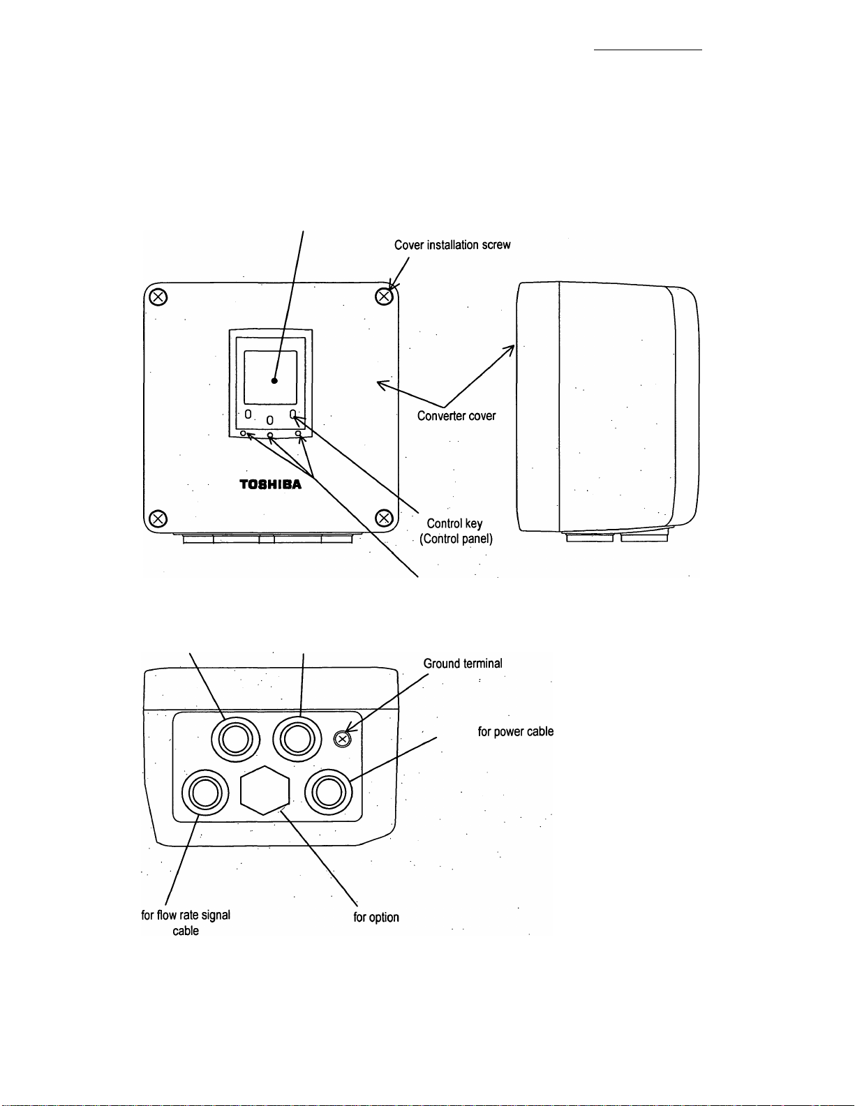
3.1 Appearance................................................................................................................................................13
3.1.1 Appearance of LF600F Type.......................................................................................................13
3.1.2 Appearance of LF602F Type.......................................................................................................14
3.2 Construction of the terminal blocks........................................................................................................15
3.2.1 Terminal Block Construction of LF600F Type..........................................................................15
3.2.2 Terminal Bock Construction of LF602F Type...........................................................................16
4. Installation............................................................................................................................................................17
4.1 Notes on Selecting the Installation Location..........................................................................................18
4.2 How to Install.............................................................................................................................................19
4.2.1 LF600FType................................................................................................................................. 19
4.2.2 LF602F Type................................................................................................................................ 19
5. Wiring................................................................................................................................................................. 21
5.1 Cables.........................................................................................................................................................22
5.2 External Device Connections and Grounding....................................................................................... 23
5.2.1 LF600F Type................................................................................................................................ 23
5.2.1 LF602F Type................................................................................................................................ 24
5.3 Notes on Wiring.........................................................................................................................................25
5.3.1 Notes on Instrumentation-Converter Wiring
5.3.2 Notes on Wiring of the LF602F Type.........................................................................................25
5.4 Wiring.........................................................................................................................................................26
5.4.1 Grounding....................................................................................................................................26
5.4.2 Terminal Treatment of Cables................................................................................................... 28
5.4.3 Cable Connection....................................................................................................................... 30
5.5 Digital I/C Connections............................................................................................................................ 31
6. Cperation..............................................................................................................................................................32
6.1 Preparatory check.................................................................................................................................... 32
6.2 Zero Adjustment........................................................................................................................................33
7. LCD Display and Controls..................................................................................................................................34
7.1 Name and Function of Each Part of LCD Display
7.2 Display Format......................................................................................................................................... 36
7.3 Basic operations....................................................................................................................................... 42
7.3.1 Mode Change...............................................................................................................................42
7.3.2 Setting and Calibration...............................................................................................................46
7.4 Configuration Items Selection Table.......................................................................................................50
7.5 Password input..........................................................................................................................................52
............................................................................
..................................................................................
25
34
- 8 -

TOSHIBA
8. Configuration Parameter Setting....................................................................................................................... 53
8.1 Configuration Items.................................................................................................................................. 53
8.2 Check/Change of Parameters.................................................................................................................. 54
8.2.1 Menu Configuration Selection Screen.......................................................................................54
8.2.2 Exciting Current Value................................................................................................................55
8.2.3 Meter Size.....................................................................................................................................57
8.2.4 Exciting Frequency..................................................................................................................... 59
8.2.5 Flow Direction Setting................................................................................................................61
8.2.6 Password Setting....................................................................................................................... 63
8.2.7 Address Setting.......................................................................................................................... 65
8.2.8 Indicating Unit............................................................................................................................. 65
8.2.9 Custom Coefficient Setting........................................................................................................ 69
8.2.10 Custom Unit Setting..................................................................................................................70
8.2.11 LCD Density Adjustment.......................................................................................................... 72
8.2.12 Switch Position Setting............................................................................................................ 73
8.2.13 Span (range).............................................................................................................................. 76
8.2.14 Damping Constant.................................................................................................................... 83
8.2.15 Low Cutoff..................................................................................................................................84
8.2.16 Current Output Setting Used When an Alarm Occurs............................................................85
8.2.17 Display Low Cut Setting.............................................................................................................86
8.2.18 Output Low Limit Setting..........................................................................................................88
8.2.19 Still Water Zero Adjustment..................................................................................................... 89
8.2.20 Digital I/O................................................................................................................................... 90
8.2.21 Count Rate (Pulse Rate), Pulse Width Setting Mode, Pulse Width........................................93
8.2.22 Preset Count Value................................................................................................................... 96
8.2.23 Preset Point Output Function.................................................................................................. 97
8.2.24 Flow Rate High, Low, High-High and Low-Low limit Alarm Setting
8.2.25 Empty Alarm Setting...............................................................................................................100
8.2.26 Self-diagnosis ON/OFF Setting
8.2.27 Alarm Output Preset Function Setting..................................................................................102
8.2.28 Rate-Of-Change Limit and Control Limit Time
8.2.29 Fixed-Value Output................................................................................................................. 105
8.2.30 Zero Offset Adjustment...........................................................................................................108
8.2.31 Parameter initial settings list..................................................................................................110
.............................................................................................
............
.....................................................
i6,F,8,A0,8,6,9,
.........
.............................98
101
103
9. Calibration......................................................................................................................................................... 111
9.1 Calibration Items.....................................................................................................................................111
9.2 Calibration Using Converter Signal Source..........................................................................................112
9.2.1 0 % Flow Rate Calibration (zero point calibration)..................................................................112
9.2.2 50 % Flow Rate Calibration...................................................................................................... 113
9.2.3 100 % Flow Rate (Span) Calibration........................................................................................113
9.2.4 Checking the Excitation Current Value...................................................................................113
10. Digital I/O Functions....................................................................................................................................... 114
10.1 Digital I/O Specifications......................................................................................................................115
10.2 Totalizer and Pulse Output...................................................................................................................116
10.3 Multi-range Functions...........................................................................................................................120
10.4 High/Low, High-high or Low-low Limit Alarm
10.5 Preset Count Output.............................................................................................................................127
10.6 Remote Zero Adjustment......................................................................................................................130
....................................................................................
125
9 -

TOSHIBA_______________________________,6,F,8.A:0,8,6,9,
10.7 Remote Selection of Fixed Value Output.............................................................................................131
10.8 Converter Failure Alarm....................................................................................................................... 132
10.9 Multiple range high/low limit alarm function (option).........................................................................133
11. Communications Function.............................................................................................................................135
11.1 Connections with the HHT Terminal....................................................................................................136
11.2 Procedures for Communication with HHT...........................................................................................137
11.3 Cautionary Notes on Communications............................................................................................... 138
12. Self-Diagnostics and Alarms..........................................................................................................................139
12.1 Self^diagnostics....................................................................................................................................139
12.2 Output Status for Errors and Alarms.................................................................................................. 142
13. Maintenance and Troubleshooting................................................................................................................143
13.1 Maintenance...........................................................................................................................................144
13.2 Troubleshooting....................................................................................................................................145
13.2.1 Flow rate is not indicated....................................................................................................... 145
13.2.2 Flow rate indication is not correct..........................................................................................146
13.2.3 Flow rate indication is not stable.......................................................................................... 147
13.2.4 When switch operation is unable...........................................................................................148
14. Principle of Operation.....................................................................................................................................149
15. Specifications..................................................................................................................................................150
15.1 Specifications....................................................................................................................................... 150
15.2 Model Number Table............................................................................................................................. 150
16. Outline Drawing...............................................................................................................................................153
16.1 LF600FType........................................................................................................................................... 153
16.2 LF602F Type.......................................................................................................................................... 154
Appendix 1 (Factory default standard value table)...............................................................................................155
Appendix 2...............................................................................................................................................................157
2-1 A system block diagram for LF600F..................................................................................................... 157
2-2 A system block diagram for LF602F......................................................................................................158
Appendix 3 (Electromagnetic Compatibility and Low Voltage Safety)...............................................................159
- 10 -

TOSHIBA ^6,F,8,A0i8i6,9,
1. Product Inspection and Storage
1.1 Product Inspection
LF60*F series electromagnetic flowmeter is shipped in a cardboard container filled with
shock-absorbing materials. Open the package carefully and check as follows:
■ Make sure the following items are included in the package.
For the integral type (when a converter and detector are united)
■1 unitElectromagnetic flowmeter main unit
LF600F
Instruction manual
-------------------------
---------------------------------------One each for the converter and detector
For the separate type (when a converter and detector are separated)
LF602F
Electromagnetic flowmeter converter
Electromagnetic flowmeter detector------------------------------------------------1 unit
Instruction manual
------------------------
----------------------------------------------
Once each for the converter and detector
1 unit
For a converter unit only
LF602F
Electromagnetic flowmeter converterinstruction manual
-----------------------
----------------One for the converter
One unit
Inspect the flowmeter for indications of damage that may have occurred during shipment.
Make sure the type and specifications of the flowmeter are in accordance with the ordered
specifications.
If you cannot find the items listed above or any problem exists, contact you're nearest Toshiba
representative.
1.2 Storage
To store the electromagnetic flowmeter after opening the package, select a storing place as
follows and keep it under the conditions described below:
Æ CAUTION
(1) Avoid places where there is direct sunlight, rain or wind.
(2) Store the product in a well-ventilated place. Avoid places of extremely high humidity or
extremely high or low temperature. The following environment is recommended:
• Humidity range: 10 to 90% RH (no condensation)
• Storage temperature: -25 to +65° C
(3) Avoid places where vibrations or mechanical shock occur.
(4) If it leaves the cover of converter open while being stored, gradual deterioration of circuit
isolation can be caused. And then don’t open the cover until it is connected with wires.
(5) To put the flowmeter temporarily on the floor, place it carefully with something, such as
stopper, to support it so that the flowmeter will not topple over.
- 11 -

TOSHIBA
2. Overview
The LF600F and LF602F electromagnetic flowmeter converter can be use in the following
hazardous (classified) locations.
This product is a converter used for electric flowmeters that measure the volumetric flow rate of
conductive fluid using Faraday's law of electromagnetic induction.
You can bring out the functions of the converter when you place it in the converter housing you
prepare and use it in combination with a fluid rate measurement detector.
The converter sends out a signal to drive the detector exciting coil, which generates a magnetic
field inside the detector. The converter receives the signal electromotive force obtained by the
detector, as signal electromotive force in proportion to the generated flow rate in the fluid using
Faraday's law of electromagnetic induction. After carrying out operation, the converter converts
the signal electromotive force to an analog signal instrumentation unified signal output and
displays the status, as a flow rate value.
i6,F,8,A0i8,6,9,
Class I, Division 2, Groups A, B, C and D,
Class n, Division 2, Groups E, F and G
Classin
Features
With a linear relationship between the flow rate and output signal, the electromagnetic flowmeter
is featured as an easy-to-read indicator. In addition to this feature, it has the following outstanding
features:
(1) Wide flow velocity range setting, such as a flow velocity range of 0-0.1 and 0~10m/s, is
achieved.
(2) The unique noise filter-out circuit and arithmetic operation processor enables you to obtain
stable output.
(3) Full graphic LCD that enables display of a large amount of information
• With a large amount of a maximum of 14 characters x 8 lines, you can easily check various
displays including bar graphs and alarm indications.
• The backlight allows you to read the indicator easily.
(4) Use of infrared switches
• Use of infrared switches allows you to perform various operations, without opening the
converter housing cover.
(5) Intelligent functions
• The widely used HART protocol communications system is used as a standard feature.
• This product supports PROFIBUS*^ communication by option.
* 1 HART protocol: “HART” stands for Highway Addressable Remote Transducer and is a
communication protocol recommended by HCF (HART communication
Foundation) for industrial sensors.
* 2 PROFIBUS: PROFIBUS, which stands for PROCESS FIELDBUS, is a kind of field bus
that is approved by international standard IEC61158. The electromagnetic
flowmeter supports PRFIBUS PA for process automation.
- 12 -

TOSHIBA
¡6iFi8|A;0j8|6j9[
3. Names of Parts
IMPORTANT
The cable glands is not provided in the conduit port of this apparatus.
Please prepare yourself for the cable glands, which could be used in Division2 hazardous locations.
3.1 Appearance
3.1.1 Appearance of LF600F Type
G)
LF600F
Figure 3.1.1 Appearance of LF600F
- 13 -
TOSHIBA
3.1.2 Appearance of LF602F Type
□
LF602F
Display section
6,F,8,A0i8,6|9.
for excitation cable
Raised portion
for output cable
Figure 3.1.2 Appearance of LF602F
- 14 -
TOSHIBA
3.2 Construction of the terminal blocks
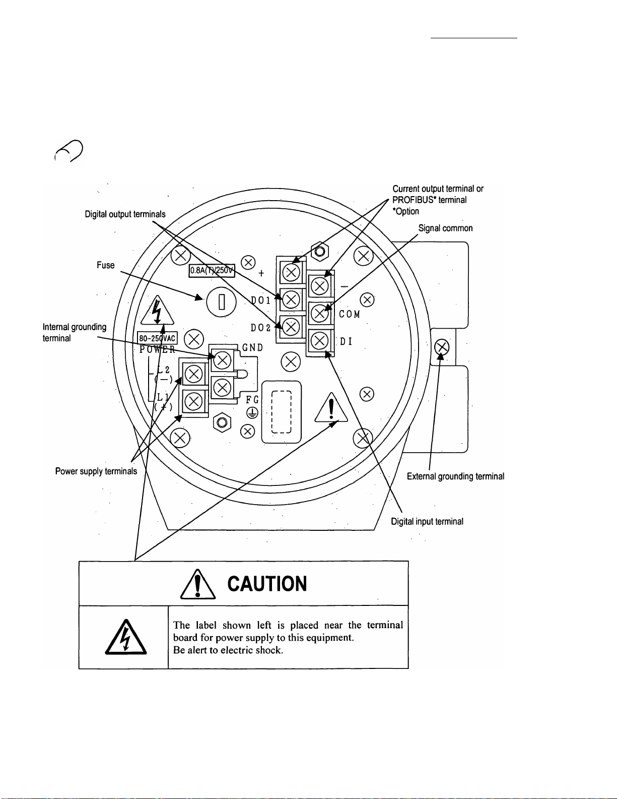
3.2.1 Terminal Block Construction of LF600F Type
When you remove the terminal block cover shown in the figure "Appearance of LF600F Type", you
can see the converter terminal block as shown below.
igj
LF600F
6,F,8,A0,8,6,9,
Figure 3.2.1 Terminal Block Construction of LF600F
- 15 -
TOSHIBA
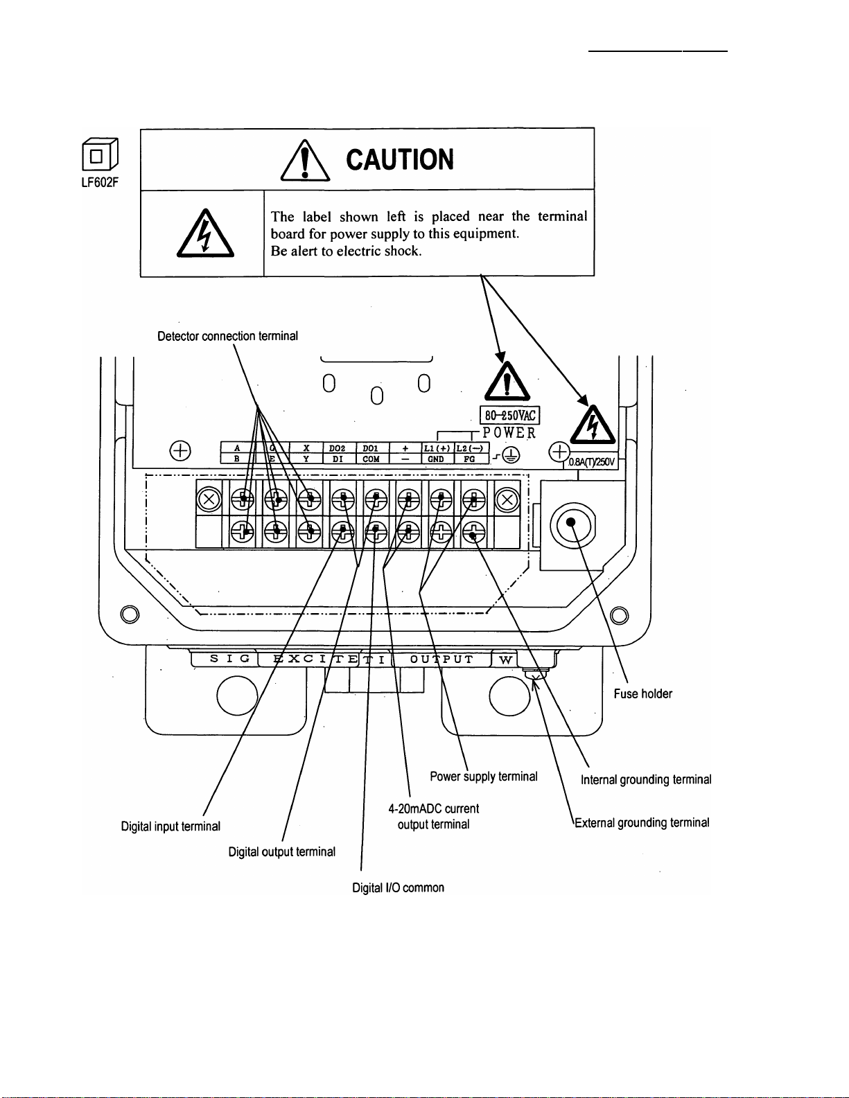
3.2.2 Terminal Bock Construction of LF602F Type
6, F, 8, A 0,8,6,9,
Figure 3.2.2 Terminal Block Construction of LF602F
- 16 -

TOSHIBA
4. Installation
Safety Precautions for Installation
Do not live circuits under environment of explosive atmospheres.
,6,F,8,A0,8,6.9,
A WARNING
0
DON’T
Do not use parts of other products.
0
DON’T
■ Do not live circuits While assembly of all components is not over.
0
DON’T
Install per the National Electrical Code for the US (NEC, ANSI/NFPA 70) and the
Canadian Electrical code for Canada (CEC, CAN/CSA-C22.1) and the drawing
3S8A2532,3S8A2533 (Refer to Appendix 2.).
O
DO
Live part of electric circuit or a high temperature department can cause explosion.
Protective performance degradation for hazardous location can cause explosion.
Protective performance degradation for hazardous location can cause explosion.
Unsuitable conduit connections for hazardous location can cause explosion.
A CAUTION
■ Ground the LF600F and LF602F
independently from power equipment.
(100 ohm or less ground resistance)
A A Operating this product without
grounding can cause electric
QQ shock or malfunction.
■ Install a switch and fuse to isolate the
LF600FF and LF602FF from mains power.
Power supply from mains
power can cause electric
shock or circuit break-down.
DO
■ Do not work on piping and wiring with
wet hands.
Wet hands may result in
V^y electric shock
DON’T
■ Use an appropriate device to carry and install
the LF600F and LF602F.
If his product falls to the ground,
injury, or malfunction of or damage to
the product, can be caused.
DO
■ Do not modify or disassemble the LF600F and
LF602F unnecessarily.
Modifying or disassembling this product
yly can cause electric shock, malfunction
or damage to this product.
DON’T
^ The label shown left is placed
near the terminal board for power
supply to the converter.
Be alert to electric shock
- 17 -

TOSHIBA
4.1 Notes on Selecting the Installation Location
This product is designed for the following environment.
• Indoor and outdoor installation • Ambient temperature: —20 to +60°C
• Altitude: Up to 2000m • Humidity range: 10 to 90%(no condensation)
• Regulation of power voltage: ± 10%
• Pollution degree 2 • Structure: IP67 (NEMA 4X)
Do not store or install the flowmeter in :
1. Places within the immediate proximity of equipment producing electrical interference (such as
motors, transformers, radio transmitters, electrolytic cells, or other equipment causing
electromagnetic or electrostatic interference).
2. Places where there is direct sunlight.
3. Places where excessive vibration or mechanical shock occurs.
4. Places where high temperature or high humidity conditions obtain.
5. Places where corrosive atmospheres obtain.
i6,F,8,A0,8,6,9,
6. Places submerged under water.
7. Place where there is slop floor. To put the flowmeter temporarily on the floor, place it
carefully with something, such as stopper, to support it so that the flowmeter will not
topple over.
8. Places of too great an elevation or constricted areas where clearance for installation or
maintenance work is not provided.
9. The standard length of the cable that connects the detector and converter is 30m. Select the
□
LF602F 30m.
converter installation location so that the distance of the detector and converter will not exceed
10. Places where there is following factors.
♦ Factors to impede infrared switch to operate properly
• Intense light such as direct sunlight and reflected sunlight by window glass or metal plate
• Place where brightness changes always such as ON/OFF of lighting
• Dense smoke or steam near the control panel
• Those attached on the control panel such as rain (dew drop), snow, ice, mud and oil, and haze due
to their attachment
• Light reflecting object near the control panel, or reflecting object such as metal plate placed
opposing to the control panel
When any of above factors is considered, take a measure for the proper operation of infrared switch
such as to place a cover or to secure a space for at least a person to stand in front of the control
panel.
When unable to avoid above factors, operate the EMF converter removing the factor by covering
the control panel by hand so that light does not shine on it, by cleaning those attached on the control
panel, or by standing in-between the reflecting object and the control panel to block the light.
- 18 -
TOSHIBA
^6,F|8iA0i8|6,9,
4.2 How to Install
4.2.1 LF600F Type
The LF600F type converter is used as one united body. The LF600F type is not installed by itself.
(S)/^ For how to install the LF600F type converter and a detector, check the type of the combined
LF600F detector and follow the instruction manual of the relevant detector.
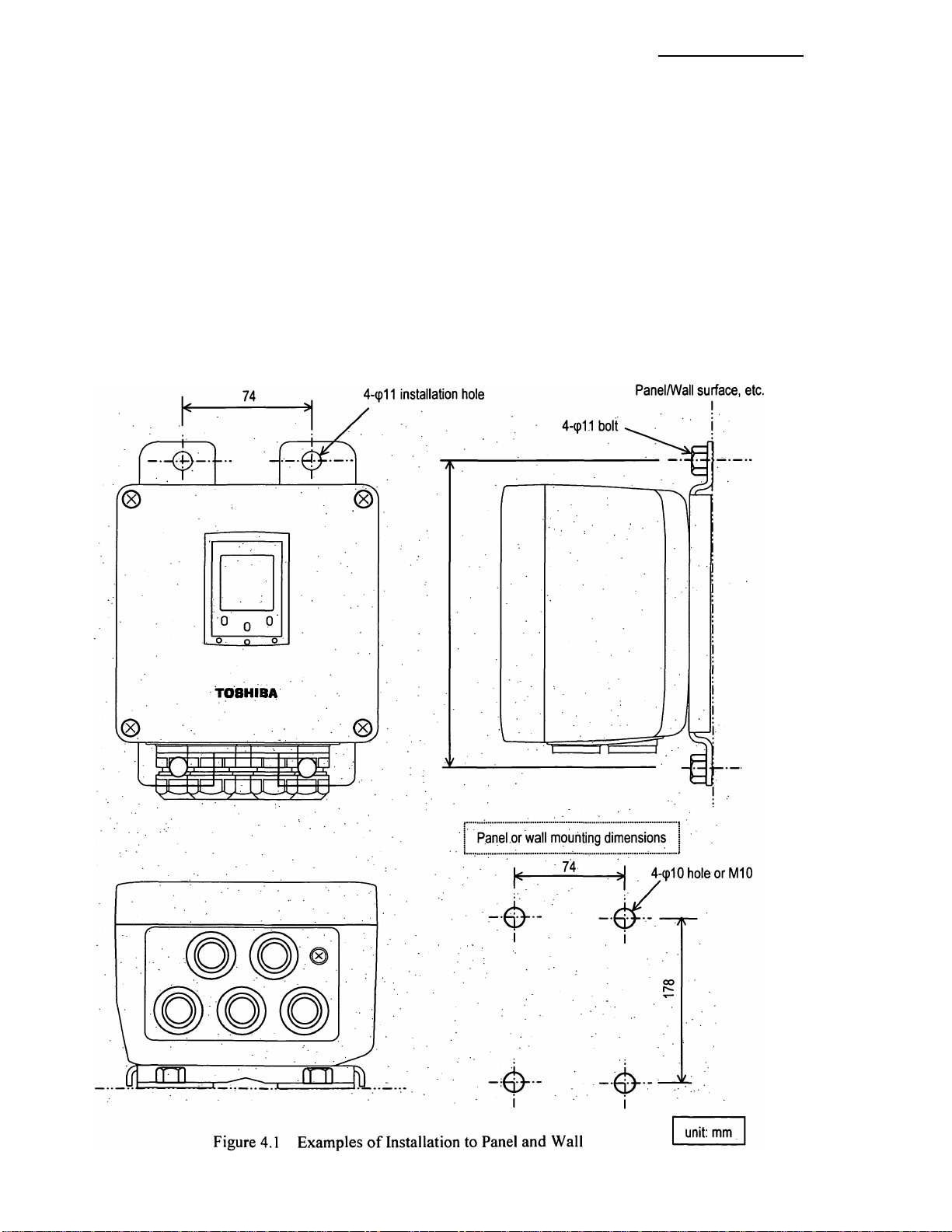
4.2.2 LF602F Type
The LF602F type can be installed on a wall or to a pipe stand. Install the converter so that the
□
LF602F opening of the converter will face the bottom.
front of the cover is positioned on the vertical plane. Be sure to install it so that the conduit
Figure 4.1 shows examples of installation to a panel and wall. Figure 4.2 shows an example of
installation to a pipe stand.
- 19 -

TOSHIBA
6|F,8iA0,8|6,9
Figure 4.2 Example of Pipestand Mounting
- 20 -

TOSHIBA
5. Wiring
DO NOT DISCONNECT WHILE CIRCUIT IS LIVE UNLESS LOCATION IS KNOWN
TO BE NONHAZARDOUS.
,6,F,8,A0,8,6,9,
/h WARNING
0
DON’T
Do not live circuits While assembly of all components is not over.
0
DON’T
Install per the National Electrical Code for the US (NEC, ANSI/NFPA 70) and the
Canadian Electrical code for Canada (CEC, CAN/CSA-C22.1) and the drawing
3S8A25323S8A2533 (Refer to Appendix 2.).
O
DO
Live part of electric circuit or a high temperature department can cause explosion.
Protective performance degradation for hazardous location can cause explosion.
Unsuitable conduit connections for hazardous location can cause explosion.
A CAUTION
■ Install a switch and fuse to isolate the
LF600F and LF602F from mains power.
Power supply from mains power
can cause electric shock or circuit
QQ break-down.
■ Do not work on piping and wiring with
wet hands.
Wet hands may result in electric
shock
DON’T
■ Do not conduct wiring work with bare
hands.
/ON Remaining electric charge even if
power is turned off can still cause
electric shock.
DON’T
Do not modify or disassemble the LF600F
and LF602F unnecessarily.
i^N Modifying or disassembling this
( product can cause electric shock,
N—X malfunction of or damage to this
DON’T product.
■ Turn off mains power before conducting wiring
work.
Wiring while power is applied can cause
electric shock.
DO
■ Ground the LF600F independently from power
equipment. (100 ohm or less ground resistance)
Operating this product without grounding
can cause electric shock or malfunction.
DO
■ For the power supply wiring and grounding wiring,
use crimping terminals with insulated sleeve.
There is a risk of electric shock due to
drop-off or loosing, and a risk of fire and
equipment trouble due to heat generation.
yy The label shown left is placed near
/jf\ the power supply terminal on the
\ converter.
■ Be alert to electric shock.
Flowmeter accuracy may be affected by the way wiring is executed. Proceed with correct
wiring taldng the precautions in following pages.
- 21 -

TOSHIBA
Notes on wiring
A CAUTION
Select the cable runs away from electrical equipment (motors, transformers, or radio
(1)
transmitters) which causes electromagnetic or electrostatic interference.
Deterioration of flowmeter circuit insulation occurs if the converter interior or cable ends get
(2)
wet or humidified. This in turn causes malfunction of flowmeter or noise problems. Avoid a
rainy day if the flowmeter is to be installed outdoors. Even indoors, prevent water from
splashing over the flowmeter. Try to finish the wiring as quickly as possible
The converter has an arrestor installed inside. Therefore, do not conduct a withstand voltage
(3)
test for the converter. To check the insulation of the converter, use a voltage of 250Vdc or
less.
After wiring, be sure to install the terminal block protection cover.
(4)
Because the excitation cable and flow rate signal cable transmit very delicate signals, pass each
(5)
□
LF602F
of them separately through a thick steel conduit tube, keep them away from the large current
wiring as far as possible, and do not install them in parallel.
,6,F,8iA0,8,6,9,
5.1 Cables
Use the kind of cables shown in Table 5.1 to wire the converter.
Table 5.1 Installation Cables
Cable name
□
LF602F
□
LF602F
Name
Power cable
Output signal
cable
Flow rate
signal cable
Excitation
cable
3-core vinyl sheathed cable or
2-core vinyl sheathed cable
The number of conductors the cable contains differs depending on
the specification of the output signal cable.
Use a shielded cable of finished outer diameter 11 to 13mm and
nominal cross-sectional area 1.25mm2.
2-core shielded chloroprene
cabtyre cable
3-core shielded chloroprene
cabtypre cable
Nominal
cross-sectional
area
2 mm^ 11~13mm
0.75 mm2
2 mm2
1.25 m2
Finished
outer
diameter
11~13m
m
11~13m
m
Description
CW-JISC3401,
IEC60695,
IEC60754,
IEC60227,
IEC60245
or equivalent
CW-SJIS-258-C
or equivalent
2PNCT-S
JIS C 3327
or equivalent
2PNCT
JIS C 3327
or equivalent
- 22 -
TOSHIBA
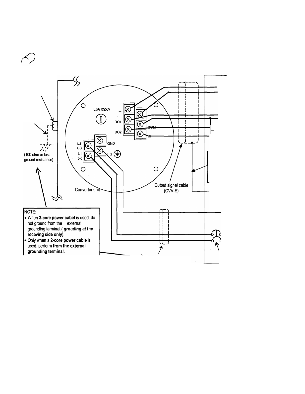
5.2 External Device Connections and Grounding
5.2.1 LF600F Type
The terminal board connections of an integral type converter LF600F are shown in Figure 5.1.
&
LF600F
Proceed with wiring as described in Section 5.4, “Wiring Procedure.”
6,F,8.A0|8|6,9,
[Instrumentation panel: Customer]
(Receiving side)
Ground terminal
IV wire
5.5mm^ or more
Current output
(4-20mAdc)
or PROFIBUS
Digital output 1
Common for DI/DO
— Digital output 2
“ Digital input
(20to30Vdc)
NOTE:
To avoid 2-point grounding,
ground the shield of the output
cable basically at the receiving
side.
IW
(100 ohm or less
ground resistance)
(100 ohm or less
ground resistance)
Power supply
Wiring breaker
Power cable (CW)
* For a 2-core cable, L1
and L2 only.
(double-pole/single-throw)
Figure 5.1 External Wiring Schematic Diagram
* Use a heavy copper braid or wire (cross-sectional area 5.5 mm^ minimum) to ground the
terminal and make it as short as possible as shown in Figure 5.1 for grounding.
Also, Avoid a common ground where earth current may flow. (An independent ground is
preferable.)
* The converter has no power switch. Install the power switch at the system side. Be sure to use a
double-pole/single-throw (both disconnection) wiring breaker.
- 23 -
TOSHIBA
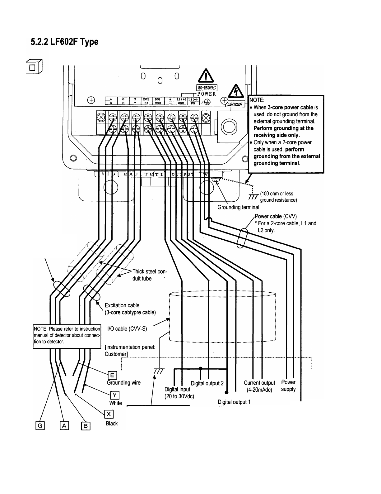
The terminal board connections of separate type converter LF602F are shown in Figure 5.1.
Proceed with wiring as described in Section 5.4, “Wiring Procedure.”
LF602F
6F8A0869
Signal cable
(2-core shielded
cabtypre cable)
Shielded wire Black White
NOTE: To avoid 2-point
grounding, ground the shield of
the output cable basically at
the receiving side.
77T
(100 ohm or less
ground resistance)
Connected detector
Figure 5.2 External Wiring Schematic Diagram
- 24 -

TOSHIBA
j6iFi8iA0|8|6|9|
5.3 Notes on Wiring
5.3.1 Notes on Instrumentation-Converter Wiring
• To avoid 2-point grounding, ground the shield of output cable basically at the receiving side.
• Use a grounding wire of IV wire 5.5mm^ or more. The size of the external grounding terminal screws is
M4. Do not share a grounding wire with other instruments where grounding current may flow. (An
independent grounding is preferable.)
• Power cable
When a 3-core cable is used: Ground with the FG terminal.
When a 2-core cable is used: Use an external grounding terminal and make the cable as short as possible.
Note that, for a replacement from the Toshiba electromagnetic flowmeter converter LF220 type, the
cable grounding position differs.
m
LF602F
5.3.2 Notes on Wiring of the LF602F Type
• The detector is shipped with a flow rate signal cable and excitation cable. Be sure to use those cables
coming with the detector.
Note: When the cable length exceeds 30m, cables may not be supplied. Check whether the
cable is supplied with the specs.
• The allowable cable length between the detector and converter varies depending on the conductivity of
the operating fluid. Refer to the instruction manual of the combined detector.
• When connecting with the detector, wire the cables in the order of the excitation cable and flow rate
signal cable.
• Because the input cables transmit very delicate signals, pass the excitation cable and input signal cable
separately through a thick steel conduit tube , keep them away from the large current wiring as
far as possible, and do not install them in parallel.
• When replacing the flow rate signal cable and excitation cable, also refer to the instruction manual of the
relevant detector. Order the detector terminal box cover packing from Toshiba or a Toshiba distributor.
- 25 -
TOSHIBA
5.4 Wiring
IMPORTANT
The cable glands is not provided in the conduit port of this apparatus.
Please prepare yourself for the cable glands which could be used in Division2 hazardous locations.
■ Do not wire cables and replace parts when
power is supplied.
Wiring work and
1 replacing parts in the
power-on state may cause
DON’T electric shock.
5.4.1 Grounding
¡6|F|8iA;0|8i6|9j
A CAUTION
■ Do not work on piping and wiring with wet
hands.
Wet hands may result in electric
1 shock.
DON’T
LF600F
(1) Grounding the LF600F type
Ground as shown in Figure 5.3. Make the grounding wire as short as possible. Use grounding wire
material of IV wire 5.5mm^ or more. Do not share a grounding wire with other instruments
where grounding current may flow. (An independent grounding is preferable.)
piping flange.
Figure 5.3 Grounding the LF600F Type
- 26 -
TOSHIBA
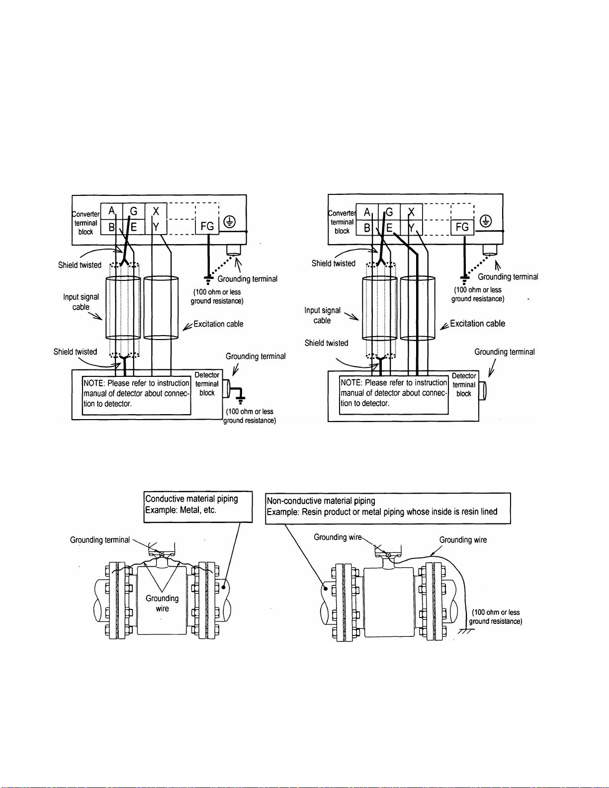
(2) Grounding the LF602F type
□
LF602F
Ground the external grounding terminal of the detector and the FG terminal of the converter (or ex
ternal grounding terminal of the converter) securely (grounding resistance 100 Q or lower). Use
grounding wire material of IV wire 5.5mm^ or more. Do not share a grounding wire with other
instruments where grounding current may flow. (An independent grounding is preferable.)
If it is difficult to perform grounding work at the detector side because of a pit installation or other
reasons, use a 3-core cable for the excitation cable and connect the E terminal of the detector to the E
terminal of the converter. (The E terminal of the converter is internally connected with the FG termi
nal and the converter case.)
6F8A0869
Figure 5.4 (a)
Wiring between Detector and Converter (For
grounding the detector, see Figure 5.5 below.)
If the piping material is conductive, connect the
grounding wires to the both ends of the piping flange.
Figure 5.5 Grounding the Separate Type Detector
Figure 5.4 (b)
Wiring between Detector and Converter
(when grounidng of the detector is difficut)
If the piping material is non-conductive, perform grounding
resistance 100Q or less.
- 27 -
TOSHIBA
^6|F,8iA0i8,6,9,
5.4.2 Terminal Treatment of Cables
Follow the procedures below to treat the terminals (at the converter side) of various cables and install
the cables to the terminal block. Use appropriate cables based on the description in Section 5.1
"Cables." Crimp a round type insulated crimp-type terminal to the end of the cables.
(1) Power cable, current output cable, digital I/O cables
The necessary cables should be ordered from the person responsible for the installation. Strip the
sheath of each conductor as shown in Figure 5.6 and attach a crimping terminal with insulated
sleeve to it. The size of the crimping terminal is as follows:
Integral type LF600F: M4
Separate type LF602F: M3.5
• Connect the power cable to terminal blocks LI and L2.
• Connect the current output cable to terminal blocks + and -.
• Connect the digital I/O cable to terminal blocks Dl, DOl, D02 and COM, as required.
Xrimping terminal-f
^ ^ 1LF602F type: M3.5
□
LF602F
Figure 5.6 Terminal Treatment of Power Cable, Current Output Cable
and Digital I/O cable
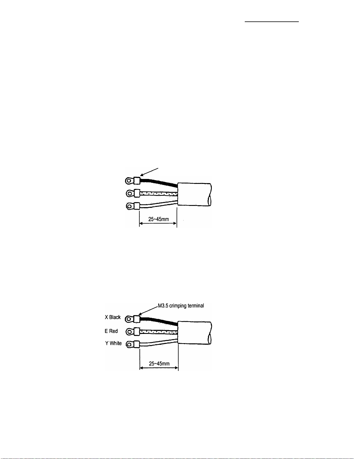
(2) Excitation cable
Strip the sheath from the end of each conductor as shown in Figure 5.7, attach an M3.5 crimping
terminal with insulated sleeve, and connect it to the terminal blocks X and Y. Connect the red
conductor to terminal block E.
Figure 5.7 Terminal Treatment of Excitation Cable
- 28 -
TOSHIBA
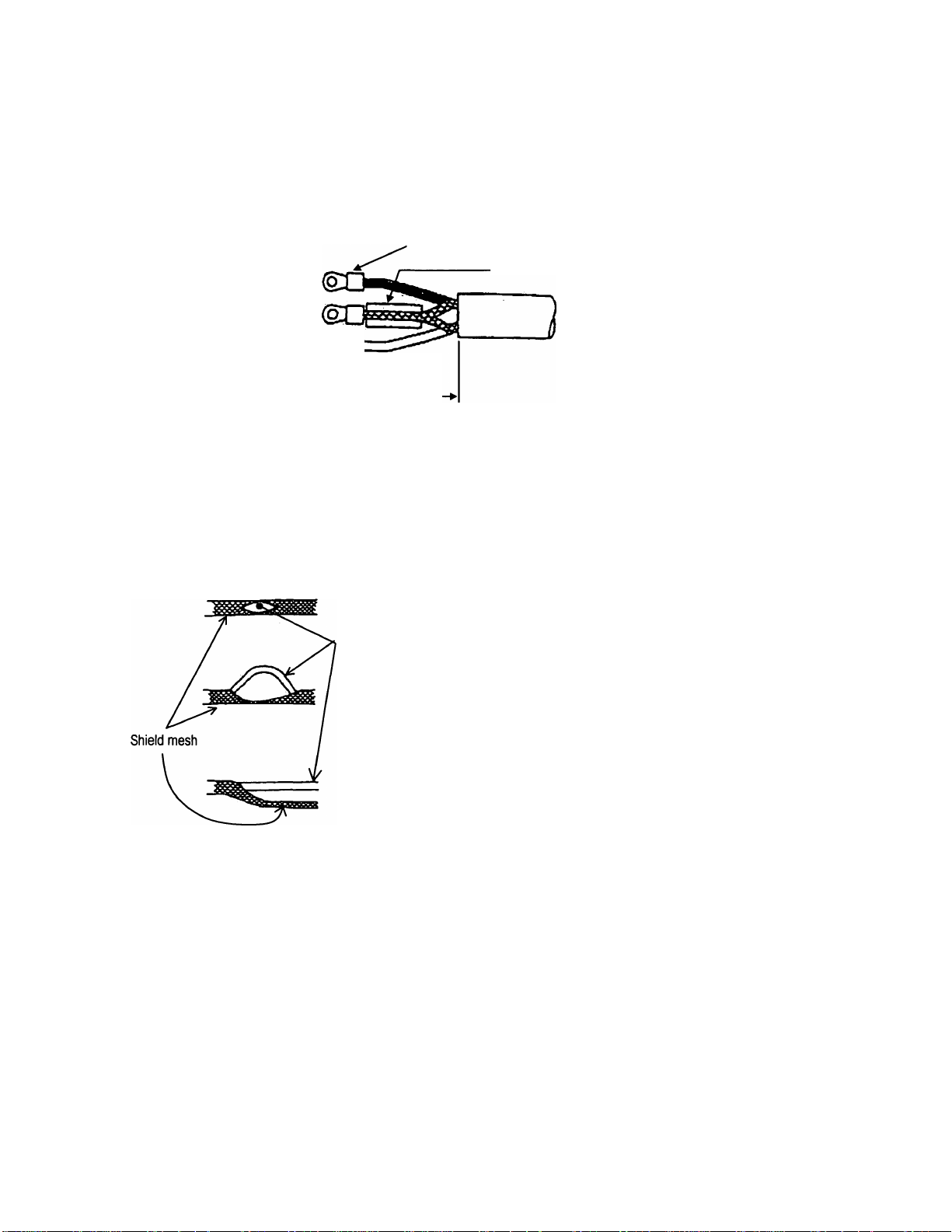
(3) Connecting the input signal cable:
Strip the sheath from the end of each conductor of a 2-core individually shielded cable as shown in
LF602F
Figure 5.9. Twist those shields and cover them with a thermal contraction tube or vinyl tube not to
make contact with the case or core wires. Then attach an M3.5 crimping terminal with insulated
sleeve as shown in Figure 5.8. Connect a crimping terminal to the A and B terminals on the terminal
block and connect to each G terminal of the detector and converter.
i6,F,8,A0,8,6,9,
,M3.5 crimping terminal
A Black
G Shield
B White (q^
25~45mm
.Thermal contraction tube or vinyl tube
Figure 5.8 Terminal Treatment of Flow Rate Signal Cable
Notes on signal cable shield processing work
When stripping an external sheath, intermediate and insulated sheath, be careful not to scratch or
cut the internal conductors and shield mesh. Do not disjoint the shield mesh but treat it as shown in
Figure 5.9.
a. Open the shield mesh with a pincette or the like.
Coated wire
b. Pull out the internal coated wires from the hole of the
shielded mesh.
c. Pull out all internal coated wires and extend the shield mesh wire.
Figure 5.9 Treating the Signal Cable Shield Mesh
- 29 -
 Loading...