

Page 1
F-IN -D Series
Electromagnetic Flowmeter for
Partially-filled Pipes
Introduction
The LF502 electr oma gnetic flowmeter uses Faraday’s
Law of electromagnetic induction in the same way as
conventional electromagnetic flowmeters to measure
the flow rate. Position of electrodes in the LF502 is so
designed that it can be used even in a partially-filled
pipe to measure the flow rate.
Improved functional magnetic field distribution technique enables a high-precision flow measurement continually from low-level to fully-filled flow conditions.
This
eliminates unnecessary piping work such as lifting
the downstream pipe section to fill the detector pipe.
Compared with flowmeters measuring the flow rate by
means of flow level, the obstructionless LF502 flowmeter does not usually allow mud, sands and other
solid sediment stay at the bottom of the detector pipe
is
and
unaffected by wave or floating solids on the fluid
surface.
The
AF100 hand-held terminal or the Model 275 HART
communicator can be used to communicate with the
flowmeter
munications protocol. See the communications output
specifications for details about the HART protocol.
from remote places using the HART com-
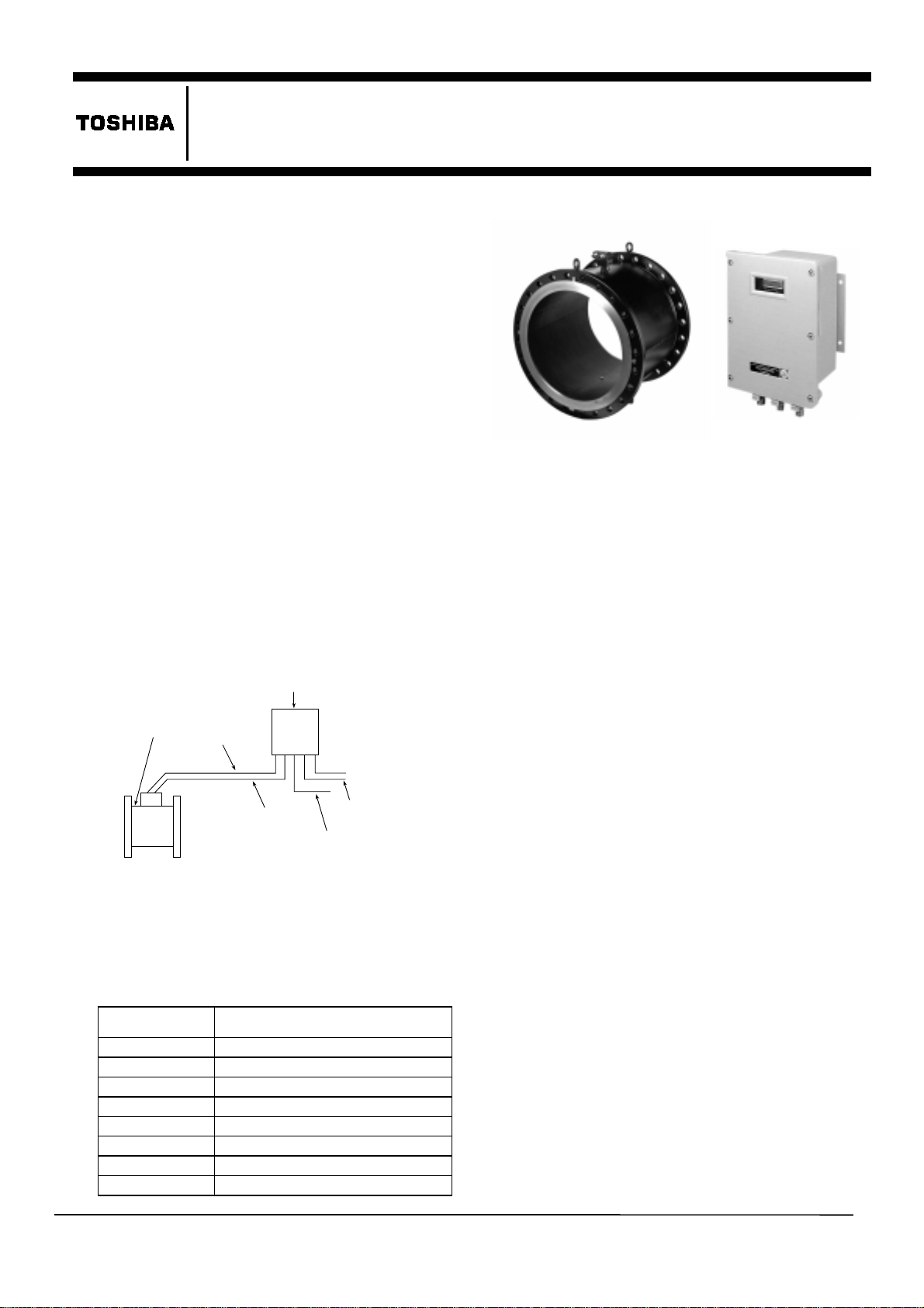
Converter
Detector
Signal cable
Excitation
cable
Power supply
4-20 mA dc
Digital I/O
LF502
150
to
(
”
to
6
Fi gu r e 2. LF502 El ec t r o m ag n et i c F l owme t e r
for Partially-filled Pip es
Fluid-level range:
x
30 mm (1 1/4”) to fully-filled condition for Meter
sizes 150 mm (6”) to 300 mm (12”)
of
x
10%
inside tube diameter to fully-filled condition
for Meter sizes 350 mm (14”) to 600 mm(24”)
Accuracy:
±2 % FS (when measurement range is
standard)
The accuracy is measured under standard
Note:
operating
conditions at Toshiba's calibration facility.
Required straight pipe length:
minimum on upstream side and
10D
5D minimum on downstream side
D is a nominal meter size.
Note:
Fluid conductivity:
Fluid temperature:
Ambient temperature:
100µS/cm minimum
0 to 55 °C (32 to 131 °F)
–10 to 50 °C (14 to 122 °F)
600
24
mm
)
”
Figure 1. LF502 Configuration
Specifications
„
Overall Specifications
Measurement range:
Meter size
in mm (inch)
150 mm (6”)
200 mm (8”)
250 mm (10”)
300 mm (12”)
350 mm (14”)
400 mm (16”)
500 mm (20”)
600 mm (24”)
Measurement range
0 –
60 m3/h (std) to 0 – 300m3/h
0 – 110 m
0 – 175 m
0 – 250 m
0 – 350 m
0 – 450 m
0 – 710 m
0 –1000 m
3
3
3
3
3
3
/h (std) to 0 – 550m3/h
/h (std) to 0 – 875m3/h
/h (std) to 0 –1250m3/h
/h (std) to 0 –1750m3/h
/h (std) to 0 –2250m3/h
/h (std) to 0 –3550m3/h
3
/h (std) to 0 –5000m3/h
„
Detector Specifications
Meter sizes:
150 mm (6”), 200 mm (8”), 250 mm
(10”), 300 mm (12”), 350 mm (14”), 400 mm
(16”), 500 mm (20”), and 600 mm (24”)
0
Fluid pressure:
to 2.0 MPa under fully-filled fluid
condition for flange-connected flowmeters
Connection flange standards:
ANSI 150, BS 16,
DIN PN16 and others.
Structure:
NEMA 4 (IP 67) Watertight (standard),
NEMA 6 (IP 68) Submersible (option)
Coating:
Phthalic acid resin coating, pearl-gray colored
(standard for watertight type) or black tar epoxy
(option for watertight type and specified
exclusively for submersible type)
EJL- 064A
Page 2

LF502
2
Principal materials:
— carbon steel
Case
Linings
— The following are the standards:
Teflon PFA for Meter sizes 150 mm (6”) to 400
mm (16”), chloroprene rubber for Meter sizes
500 mm (20”) and 600 mm(24”)
Electrodes
Grounding rings
See Table 1 for optional materials and other
— 316L stainless steel (standard)
— 316 stainless steel (standard)
related information.
„
Converter Specifications
Input signals
Analog input:
voltage signal from detector and is
proportional to process flow rate
Digital input (DI)
Voltage signal: High level 20 to 30 V
Low level 2 V
Input resistance: 2.7 k:
Number of inputs: one point
DI function
— One of the following functions can
be assigned to DI signal:
• Unidirectional 2-range switching signal
(lower range with high DI voltage level)
• Bidirectional 2-range switching signal
(lower range with high DI voltage level)
• Totalizer start/stop
— Starts and stops the
built-in totalizer. (Totalizer starts with high DI
voltage level and stops with low DI voltage
level.)
• Zero adjustment
— Starts zero adjustment (on-
stream at zero flow rate) when DI voltage level
low after remaining high for 10 to 20 seconds.
goes
• Fixed-value outputs
— Outputs fixed values
for current output (and pulse output if used).
Outputs fixed values when DI voltage is high.
Output signals
Analog output:
4–20 mA
dc;
Load resistance 0 to 1 k:
Digital outputs:
— 2 points (D1 and D2)
Output type: Solidstate relay contact outputs
(non polarity)
Capacity: 150 V
150 V
dc, 150 mA maximum or
ac, 100 mA maximum (peak)
Number of outputs: Two points
D1 and D2 functions
— Two of the following
functions can be assigned to D1 and D2.
•
Pulse output (available only for D1)
Pulse rate: 3.6 to 360000 pulses/hour
Pulse width: 5 to 100 ms (but less than half of
the period for 100 % flow rate)
• Multi-range selection outputs
(1) One point (D1 or D2) output
Unidirectional 2-range automatic selection
signal or bidirectional 2-range automatic
selection signal
dc or less
dc
(2) Two point (D1 and D2) outputs
Unidirectional 4-range automatic selection
signal or bidirectional 4-range automatic
selection signal
•
High and/or low limit alarm outputs
Outputs an alarm signal if the flow rate output
goes above high limit value or below low limit
value
Setting range: –10 to 110 % of range
Output
•
Empty pipe alarm output
status: Contact ON when alarm occurs.
Outputs an alarm signal if the detector pipe is
emptied.
Output
•
Preset point output
status: Contact ON when alarm occurs
Outputs a signal when the built-in totalizer
count reaches the preset point.
Setting range: 1 to 999999 counts
Output
•
Converter failure alarm output
status: Contact ON when alarm occurs
Outputs an alarm signal if the converter detects
an erroneous condition other than high/low
limit or empty pipe alarm conditions.
Communications output
superimposed on 4–20 mA
— A digital signal is
dc current signal
(conforms to the HART protocol).
1
Load resistance: 240 : to
k:
Load capacitance: 0.22 µF maximum
HART (Highway Addressable Remote
Note:
Transducer) protocol is a communications
protocol for industrial sensors recommended by
HCF (HART Communication Foundation).
Output display:
2-line,16-character LCD display
(backlit) shows flow rate and total flow in various
engineering units. Up to two set of data can be
displayed.
Damping:
Parameter settings:
5 to 600 s
Configuration parameters can
be set using the control keys on the LCD display.
Zero and span calibration:
Built-in calibration signal source allows converter
unit check.
Zero adjustment:
Zero point adjustment can be
started by pressing a combination of control keys
on the LCD display.
Conditions when power fails:
The output and display will remain as follows
when power fails. Parameter setting values are
stored in non-volatile memory and the values will
be re-stored
when the power returns to normal
condition.
• Current output: 0 mA
dc
• LCD display: No display
Digital output: OFF
•
Page 3

LF502
Power supply:
One of the following power supply
specifications can be selected:
• 100 to 120 V
ac (90 to 132 V ac), 50/60 Hz
• 200 to 240 V ac (180 to 264 V ac), 50/60 Hz
(option)
• 24 V dc (22 to 27 V
Power consumption:
Surge protection:
the
power supply and current signal output circuit.
Cast aluminum
Case:
Coating:
Painting color:
Structure:
Melamine resin
Light gray (munsell N7)
NEMA 4 (IP 67) Watertight
Cable connection port:
dc) (option)
approximately 24 VA
Surge protectors are installed in
Rc(PT) 3/4 male screw
Vibration resistance:
No resonance to the following levels of vibration:
• 5 to 33 Hz with acceleration of 9.8 m/s
Avoid
Note:
using the flowmeter in an environment
with constant vibration.
Installation
„
Dimensions
2
Unit: mm
JIS 10K flange dimensions:
Meter
size (mm)L1(mm)L2(mm)L3(mm)
150
200
„
Dimensions
266 245 385 8 approx. 35
300 271 436 8 approx. 80
Roll-prevention base
No. of
bolts
Mass
(kg)
Unit: mm
Figure 4. Detector Dimensions for Meter Sizes
250 mm (10”) to 600 mm (24”)
See the following tables for dimensions of L1, L2 and
L3 in Figure 4 above, and the number of bolts required
for each flange.
Figure 3. Detector Dimensions for Meter Sizes
150 mm (6”) and 200 mm (8”)
See the following tables for dimensions of L1, L2 and
L3 in Figure 3 above, and the number of bolts required
for each flange.
BS16 and DIN PN16 flange dimensions:
Meter
size (mm)L1(mm)L2(mm)L3(mm)
150
200
266 245 388 8 approx. 35
300 271 441 12 approx. 80
No. of
bolts
Mass
(kg)
ANSI class 150 flange dimensions:
Meter
size (inch)L1(inch)L2(inch)L3(inch
6
10 1/2 9 5/8 15 1/8 8 approx. 78
8
11 3/4 10 5/8 17 1/2 8 approx. 178
No. of
bolts
Mass
(lb)
BS16 and DIN PN16 flange dimensions:
Meter
size (mm)L1(mm)
250
300
350
400
500
600
350 306 509 12 approx. 110
400 329 559 12 approx. 120
450 351 611 16 approx. 130
500 386 676 16 approx. 180
600 401 758 20 approx. 190
600 452 872 20 approx. 250
L2
(mm)L3(mm)
No. of
bolts
ANSI class 150 flange dimensions:
Meter
size (i nch)L1(inch)L2(inch)L3(inch)
10
13 3/4 12 20 1/8 12 approx. 244
12
15 3/4 13 22 3/4 12 approx. 267
14
17 3/4 13 7/8 24 7/8 12 approx. 289
16
19 5/8 15 1/4 27 3/8 16 approx. 400
20
23 5/8 15 3/4 30 3/8 20 approx. 422
24
23 5/8 17 3/4 34 5/8 20 approx. 556
No. of
bolts
JIS 10K flange dimensions:
Meter
size (mm)L1(mm)
250
300
350
400
500
600
350 306 506 12 approx. 110
400 329 551 12 approx. 120
450 351 596 16 approx. 130
500 386 666 16 approx. 180
600 401 738 16 approx. 190
600 452 849 24 approx. 250
L2
(mm)L3(mm)
No. of
bolts
Mass
(kg)
Mass
(lb)
Mass
(kg)
3
Page 4

LF502
4
„
Dimensions (Converter)
Flow regulation
valve etc1
Observation window
Detector
Unit: mm
Mass: approx. 18 kg
(including mounting bracket)
Four-Dia. 12 holes
Figure 5. Converter Dimensions
Piping Precautions
„
(1) Flange connection
The flowmeter has upstream and downstream
flanges on the ends of detector pipe. Connect
these flanges with the flanges on both sides of
pipeline bore using connection bolts after
inserting a packing between them. See Figure 6.
Tighten the bolts in even increments diagonally
across.
Observation
window
Upstream
flange
Downstream flange
Observation window
10D minimum
The length of reducers, if used, can be
Note:
5D minimum
counted as a part of straight pipe length.
Figure 7. Required Straight Pipe Length on
Upstream and Downstream Sides
External Connections
„
Signal cable
(2-wire shielded
sheathed cable)
Excitation cable
(3-wire sheathed cable)
Digital I/O cable
(multi-wire
shielded cable)
Current output cable
(2-wire shielded cable)
Power cable
(2-wire cable)
Figure 8. Converter Terminal Connections
Signal cable (2-wire shielded s heathed cable)
Thick walled steel conduits
Excitation cable (3-wire sheath ed cable)
Grounding
terminal
(M6 screw)
Intermediate
voltage (IV)
wire, 5.5 mm
minimum
100 • or less
ground resistance
2
Packing
Flow direction
Figure 9. Detector Terminal Connections
Detector
Figure 6. Flange Connection
„
(2) Required straight pipe length
The straight pipe length is required to prevent
uneven flow velocity and a disturbance on the
fluid surface in the detector pipe. The required
straight pipe length should be as follows:
• Downstream side: L = 5D minimum
• Upstream side: L = 10D minimum
where,
L = straight pipe length (straight pipeline length
+ half length of detector pipe length)
Wiring Precautions
(1) Be sure to use thick walled steel conduit (22
mm) for signal and excitation cable wiring
between the detector and converter. The
conduit screw is R(PT)1/2. Use flexible
conduits at the cable outlets of the detector as
needed.
(2) Make the grounding wire as short as possible.
Do not use a common ground shared with other
equipment where earth current may flow.
independent
earth ground is recommended.
An
Page 5

LF502
)
)
)
)
)
Q
)
)
)
(
)
(
(
)
p
(
)
)
)
p
)
p
)
p
g
poxy
poxy
poxy
)
Ordering Information
1. When ordering the LF502 flowmeter, refer to
Table 1 and 2 (Type Specification Codes). An
entry must be made for each of the columns in
each of these tables.
2. Fluid characteristics:
(1) Type of fluid to be measured and its
characteristics
(2) Fluid temperature
(3) Fluid pressure
(4) Electrical conductivity of the fluid
3. Measuring range
4. Digital I/O specifications
5. Ordering scope:
(1) Actual flow calibration data:
6. Other items
Specifications other than standard items
(required or not)
Table 1. Type Specification Code
( Model LF502 Flowmeter)
Model Specification Code
K 150 mm (6"
L 200 mm (8"
M 250 mm (10"
N 300 mm (12"
P 350 mm (14"
R 500 mm (20"
S 600 mm (24"
C ANSI 150
F BS16
H DIN PN16
J JIS 10K
Z other
B SUS316L+SUS316
C SUS316L+SUS316L
D Ti
E Hastelloy C+Hastelloy C
F SUS316L+SUS304
Z other
T Teflon PFA
C Chloro
Z other
A 100 to 120 V ac, 50/60 Hz
B 24 V dc
C 200 to 240 V ac, 50/60 Hz
Z other
A Panel, wall mount (carbon steel SS400
B Panel, wall mount (304 stainless steel
C Pi
D Pi
Z other
A not provided
Z other
B 30 m
C other len
B Phthalic acid resin
C Black tar e
D Black tar e
E Black tar e
Z other
Description
LF502 Electromagnetic Flowmeter
Meter size
400 mm (16"
Connection flange standard
Electrode and Grounding Ring Material
titanium)+Ti
Lining Material
rene rubber
Power Supply
Converter Mounting Bolts and Nuts
e mount (carbon steel SS400
e mount (304 stainless steel
Detector Connection Bolts, Nuts and
Packings
Dedicated Preformed Cable
rovided
ths, provided
Coating of detector
(for submersible type
standard.
titanium
standard
resin 0.3 mm
resin 0.5 mm
resin 0.5 mm
Size
AB
Size groups.
A: 150 mm (6”) to 400 mm (16”)
B: 500 mm (20”) and 600 mm (24”)
Size code explanati on:
Standard
Option
Not available
–
5
Page 6

Year 2000 Com plianc e:
„
This equipment does not have any clock in itself. Thus, there is no problem in the
year 2000 com pliance .
Misuse of this product can result in damage to property or human injury.
Read related manuals carefully before using this product.
Specifications are subject to change without notice
Printed in Japan 11/98 (TDOC)
© TOSHIBA Corporation 1998
All Rights Reserved.
EJL- 064A
 Loading...