

Page 1

TOSHIBA
6F8A0774
ELECTROMAGNETIC FLOWMETER
MODEL LF494 / LF404
INSTRUCTION MANUAL
TOSHIBA CORPORATION
Page 2

TOSHIBA
NOTICK
This Manual is designed to assist in installing, operating, and maintaining the
LF494/LIH04 electromagnetic: flowmeter, i’or safely reasons, and to obtain the opti
mum performance from the flowmeter, read this Manual thoroughly before working
with the product. Keep the Manual within easy reach fcjr reference whenever needed.
The flowmeter to which this Manual refers is NOT designed for applications m which
the functioning of this product is critical to human safety, such as:
♦ Main cejntro! syaicms of nuclear power plants; safely systems in nuclear facilities
• Control systems of medical equipment, including life support machines.
6F8A0774
or other ciilical control lines directly affecting human safety.
NOTES
L The reproduction of the contents of this Manual in any form, whether wholly or in part, is
not permitted without explicit prior consent and approval.
2. 1’hc information contained in this Manual is subject to change or review without prior
notice.
3. Be .sure to follow all safety, operating and handling precautions described in this Manual
and ihe regulations in force in the country in which this product is to be used.
HART is a registered trademark of ihe HART Ccrnmunication Foundation,
Teflon is a rcgislcrcd trademark of the DuPont Company.
Forth F.dition
October. 2000
€> Copyright 1999, 2000 hy To.shiha Corporation. All rights reserved.
- 1 -
Page 3

TOSHIBA
SAFETY PRECAUTIONS
Safety signs and labels affixed to the product and/or described in this manual give important
information for using the product safely. They help prevent datnagu lo property and obviate
hazards for persons using the product,
Make yourself familiar with signal words and symbols used for safely signs and labcJs, Then
read the safety precautions that follow to prevent an accident involving personal injury,
death or damage to property.
Explanation of signal words
The signal word or words arc used to designate a degree or level of hazard seriousness.
The ssignal words used for the product described in this manual arc WARNING and
CAUTION.
A WARNING
6F8A0774
Indicates a potentially hazardous situation
which, if not avoided, could result in death or
i^erious injury.
Safety .symbols
Indicates a potentially hazardous situation
A CAUTION
rhe following symbols are used in safety signs and labels affixed to a product and/or in the
manual for giving safety instructions.
Indicates an action that is prohibited. Simply DON'T do this action.
The prohibited action is indicated by a picture or text inside or next to
0
•
Л
the circle
Indicates an action that is mandatory, DO this action,
1 he mandatory action is indicated by a picture or text inside or next to
the circle.
Indicates a potential hazard. The potentially hazardous situation is
indicated by a picture or text inside or next to the triangle.
w hich, if not avoided, may result in minor lo
moderate injuries or in property damage.
- г -
Page 4

TOSHIBA
SAFETY PRECAUTIONS
Safety Precautions for Installation and Wiring
A WARNING
Do not diNCOTinecl while circuit h live unless k>cntion is known lo be nonhuzardous.
6,F8A0 7 7 4.
0
DONT
I Oo not modify or disassemble the enclosure,
xdiy Strength dcgtadsition and defects of enclosure can cause explosion.
DONT
Do not use parts of other products.
0
DONT
Do not live circuits While assembly of all components is not over.
0
DONT
Install per the National Electrlciil Code for the LS (NEC, ANSI/NFPA 70)
and the Canadian Electrical code for Canada (CEC, CAN/CSA>C22J).
О
DO
Live pari of electric circuit ora high temperature department can cause
explosion.
Protective performance degradation for hazardous location can cause
explosion.
Protective performance degradation for hazardous location can cause
explosion.
Unsuitable conduit connections for hazardous location can cause ex
plosion.
A CAUTION
■ Turn off mains power before working
on pipes.
Working on pipes while
power is applied can cause
QQ electric shock.
■ Install a switch and fuse to isolate the
LF494/LF404 from mains power.
Power supply from mains
power can cause electric
□ 0 shock or circuit breakdown.
■ Use an appnipriate device to carry
and install the LF494/LF4Q4.
If this product falls to the
ground, injury, or malfunction
of or damage to the product,
can be caused.
■ Du not modify or disassemble the
LF494/LF404 unnecessarily,
Modifyingordisasscinhling
( this product cart cause electric
shuck, malfunction uf or
DON T damage to this product.
- 3 -
Page 5

TOSHIBA
SAFETY PRECAUTIONS (continued)
Safety Precautions for Maintenance and Inspection
CAUTION
■ Turn off mains power before
conducting wiring work.
Wiring while power is applied can cause electric shock,
DO
■ Do not condnet wiring work with bare
hands.
Remaining electric charge
■ Ground the LF494/LF404 indepen
dently from power equipment,
^^9 grounding can cause electric
■ Use compression terminal lugs with
insulation sleeve for the termmul
block and GND terminal.
I even if power is turned off
DON’T
■ Do not work on piping and wiring w ith
wet hands.
f J electric shock.
DON’T
can still cause electric shock.
Wet hands may result in
^|\ pow'cr input.
/ J \ (A black border and symbol on
6F,8A0 774
Operating this product without
shock or mal fu net ion.
Loose connections can cause
electric shock, fire from
excessive current or system
malfunction.
The label shown left is placed
near the terminal board for
yellow triangle)
Be alert to electric shock.
■ Do not touch the flowmeter main
body when high temperature fluid is
being measured.
The fluid raises the main y^“V Wiring while power is applied
i body temperature and can
cause burns when toucheil.
DON’T
■ Do not conduct wiring work with wet
hands. yy neaj ihe icrininal board for
1 Wet hands may result in
electric shock.
DON’T
■ Do not use a fuse other than the one Use a rated fu.se as follow^]
¡»pvcifled.
Using a fuse other than the
\ one specified can cause
V, ;V system failure, damage or
mal ft! action.
DON’T
■ Do not conduct wiring work when
power is applied.
i can cause electric shock.
DON’T
The label shown left is placed
/w\^ power input.
/ (A black border and symbol on
yellow triangle)
Be alert to eleciric shock.
Fuse rating:
* 1 A;250V for 100 to 24t)Vacor llOVdc
• 2A^250V for 24 V dc
Dimensions:
Diameter 5.2 inm x 20 mm
Melting time characteristic:
Normal blow |
Disclaimer
Toshiba does noi 9ccep[ liitbility for any dsimagc or loss, msuerial or personal, caused its a
direct or indirect result of the operation of this product in connection with, or due to, the
occurrence of any event of force majeurc (including fire or earthquake) or the misuse of
this product, whether iutcntiounl or aeddentaJ.
- 4 -
Page 6

TOSHIBA
Handling Precautions
■ To obiairi the opiimutn pcrforiimnce from the LJ"494/LF4C4 flowmeter for yeiirs of
coHtinuou!» operation, observe Ihc following preciiutions.
(1) Do not store or instiiJl the flowmeter in:
(2) Exccjlc wiring securely and correctly,
6F8A0774
• places where there is direct sunlight. If this is unavoidable, use an appropriate
sSunshade,
• places where excessive vibration or mechanical shock occurs,
• places where high i строга lure or high humidity conditions obtain,
■ places where corrosive atmospheres obtain,
• places submerged under water,
To put the flowmeter temporarily on the floor, place ¡t carefully with something to
support it so that the tlowmcicr will not topple over,
Ground the flowmeter whth 1Ш ohm or less ground resistance* * Avoid a common
ground used with other equipment where earth current may flow. Ал independent
ground is preferable
(3) Seal the cable thoroughly at ths cable gland so that the cable is kept airtight. The
apparatus should not be provided with the cable gland. Please prepare yourself lor
the cable glands which could he used in Division 2 hazardous locations.
(4) Make sure the fluid to be measured will not freeze in the detector pipe. This can
cause damage to the detector pipe.
{5) Select appropriate wetted materials suited for the process fluid to be measured.
Otherwise, fluid leakage due to corrosion can be caused,
(6) The converter housing covers ¿re lightened securely at the time of shipment. Do
not remove these covers or glands unless it is necessary to wire new cables or re
place old ones. Otherwise, gradual deterioration of circuit isolation or damage !o
this product can be caused. Tighten the covers securely again if they have hcca re
moved.
- 5 -
Page 7

TOSHIBA
Handling Precautions (continued)
(7) Observe the lollowing precautions when you open the converter housing cover:
• Do not open the cover in the open air unprotected ugainsi rain or wind, I'his
can cause eieciiic shock cr cause damage to the flowmeter electronics,
* Do not open the cover under high ambient teraperaitire or high humidity
conditions or in corrosive atmospheres. This can cause deterioration of
system accuracy or cause damage to the flowmeter electronics,
(8) ThisS product may cause interference to radio and television sets if they are
used near the installation site. Use meta! conduits etc, for cables to prevent
this interference.
(9) Radio transmitters such as transceivers or cellular phones may cause interference
to the flowmeter if they are used near the installation site . Observe the following
precautions when using them;
• Do not use a radio transmitter while the cover of flowmeter converter is open.
» Do not use a transceiver whose output power is more than 5 W.
• Move the antenna of a radio transmitter at least 50 cm away from the ilowtneter
and signal cables when using it,
• Do not use a radio transmitter near the flowmeter while it is operating online.
The transmitter’s output impulse noise may interfere with the flowinder.
• Do not install a radio transmitter antenna near the flowmeter converter and
signal cables,
6F8A0774
(10) For reasons of flowmeter failure, inappropriate parameters, unsuitable cable con
nections or poor jnstallaiion conditions, the flowmeter may not operate properly.
To prevent any of these problems causing a system failure, it is recommended that
you have preventive measures designed and installed on the flowmeter sigttal re*
ceiving side.
- 6 -
Page 8

TOSHIBA
TabJe of Contents
6F8A0774
SAFETY PRECAUTIONS
Hiliidling Precautions .....................................
1, Product Inspection and Storage ''
1.1 Product Inspection
L2 Storage
...............................................
...........................
2* Overview .....................................................
3- Names of Parts
4, Installation
4.1 Location
..............................................
...................................
...........................................
4.2 Mounting Procedure..........................
4.3 Piping Connections
5h Wiring
...........................................
..........................
5.1 Cables ...............................................
5.2 External Device Connections and Grounding
5.3 Digital I/O Connections
5.4 Wiring Procedure
6. Operation ■ •
........
........................................
...................
.............................
6.1 Preparatory Check ............................
G.2 Zero Adjustment
7* LCD Display and Controls
...............................
.....................
7.1 Outline ..............................................
7.2 Display Formal .................................
7.3 Basic Operations
..............................
7.4 Configuration Items Scleclion Tabic
7.5 Password Input
8. Configuration Parameter Setting
.................................
8.1 Configuration items .........................................
8.2 Checking or Changing Parameters
9* Calibration ..................................................
..................
’ 2
■ ■ 5
. . . 9
9
. 9
- 10
■ ■ II
■ 14
15
' 16
■ ■ 18
■ ‘ 23
■ ■ 25
25
■ ■ 27
■ ‘ 28
30
- 30
■ 31
■ ‘ 32
■ ■ 32
34
36
■ ' 42
43
' 44
- 44
‘ 44
101
9.1 Calibration Items .............................................
9.2 Calibration Using Converter Signal Source
- 7
101
102
Page 9

TOSHIBA
6F8A0774
10. Digital I/O Functions
10.1 Digital I/O SpecificaiiOQS
.........................................
...................................
10.2 Totalizer and Pulse Output ....................................
10.3 Multi-range Functions ...........................................
1G.4 High and Low Limit Alarms
10.5 Empty Pipe Alarm
10k6 Preset Point Output
..............................................
..............................................
10 J Remote Zero Adjustment
................................
......................................
10.8 Remote Selection of FiTfccl Value Output
10.9 Converter Failure Alarms
IL Communkatinns Function
.....................................
.....................................
11.1 Communications with llic AFIOO Terminal
11.2 Communications Procedure
1L3 Cautionary Notes on Communications ..................
12, Self-Diagnostics and Alarms .................................
12.1 Self-Diagnostics ....................................... ............
12.2 Output Status for Errors and Alarms
13, Maintenance and Troubleshooting
13H Maintenance
13.2 Troubleshooting
14, Principle of Operation ......................................
.......................
....................................................
......................
...................................
....................
-
.
15, Specifications ..................................................................
15.1 Flowmeter Specifications ■ ■ —
..........................
15.2 Type Specification Code .......................................
16, Outline Dimensions .
Appendix 1 . Electromagnetic Compatibility and Low Voltage
Electromagnetic Compatibility
......................................................
................................................
Low Voltage Safety.......................................................* - . . -
Safety
106
107
108
113
118
120
121
125
126
127
128
J28
129
130
131
131
134
135
136
139
142
143
143
148
151
152
152
153
- 8 -
Page 10

TOSHIBA
Ь Product Inspection and Storage
upon iirrival of the produt;i packiigc» open Ihc package and check the items contained inside.
If you do not intend ю install the product soon after opening the package, store Ihc product
and other related items in a place such as described in 1,2 below,
LI Product Inspection
The LF494/LF404 electromagnetic flowmeter is shipped in a cardboard container filled with
shock-absorbing materials. Open the package carefully and check as follows:
■ Make sure the following items arc included in the package.
(1) Model LF494/LK404 Electromagnetic Flowmeter*...,* i
(2) Instruction Manual
■ Inspect the flowmeter for indications of damage that may have occurred during shipment.
■ Make sure the type and specifications of the flowmeter are in accordance with (he
ordered spccillcations.
If you cannot find the items listed above or any problem exists, contact your nearest
Toshiba representative.
6F8A0774
..................................................... |
1.2 Storage
To store the I.r494/LF404 flowmeter after opening the package, select a
storing place as follows and keep it under the conditions described below:
(1) Avoid places where there is direct sunlight, rain or wind.
(2) Store the product in a weli-vemilaicd place. Avoid places of extremely high
humidity or extremely higher low temperature. The following environment is
recommended:
* Humidity range: 10 to 90% RH (no condensation)
• LStoruge temperature: -15 to +65* C
(3) Avoid places where vibratioiis or mechanical shock occur.
(4) Uo not leave the converter housing cover open . Open the cover only w'hen
you actually start wiring cables. I.eaving the cover open can cause gradual
deterioration of circuit isolation.
(i) To put the flowmieter temporarily on the floor, place it carefully wi\U something
to support ii so that the flowmeter will not topple over
- 9 -
Page 11

TOSHIBA
2, Overview
6F8A0774
The LP494/LF404 ciectromagiiclic flowmeter can be use in the following hai;ardous (clas
sified) locations,
(1) FM Approval
Class I , Division 2» Groups B, C and D,
Class n , Division 2, Groups K and G
Class IIE
(2) CSA Certification
Gass I , Division 2, Groups B, C and D,
Class U, Division 2, Groups E, F and G
Class in
The device measures the volumetric flow rates of electrically conductive materiaU on
the basis of Faraday's J.aw of electromagnetic induction.
The device consists of two unit.s; the detector» through which the fluid to be measured
flows, and the converter, which receives the electromorive force signals from the
delector, then converts the signals into the 4—20 mA dc signal.
Model LF494/LF404 is a sanitary elcctromagneiic flowmeter designed for applications
handling food and beverages. Sani'.ary flowmeters must be sinictured in such a way dial
operation and handling is simple, easy and thorough for the purpose of sanitary control
such as cleaning, sterilizing and drying, llic flow-meter has no obstacles in the flow
stream and it is designed to provide indispensable conditions for sanitary control and is
fit for flowrate measurcjncnt for food and beverages.
Features
Model LF494/LF404 sanitary flowmeter has Ihe following features:
(J) Fluid flow is not obstructed and pressure loss is negligible.
Toshiba's original noisc-suppression circuit with signal processing capabilities ensures
(2)
a stable oulpul.
Has no moving parts and flow indication is quick with high accuracy even under low'
(3)
flowrate measurement conditions.
Equipped with a ferrule, compatible with ISO clamp connection, at both ends of the
(4)
detector. They can be mounted or dismounted easily and securely.
No obstacles in the flow stream and nowhere remains the fluid along the detector pipe.
(5)
Thus deterioration or corrosion of fluid does not <xxmr.
High accuracy, ±0,5% of rale is possible for 0.3-10 m's velocity range.
(fi)
0,1 lo 0.3 m^s range is available oplionaljy.
The flowmeter has various flow measurement output and control functions as standard
(7)
specifications and the optional LCD display for convenient parameter settings.
• 'I’hcse functions can be selected with control keys on the panel.
Intelligent functions
(S)
* The widely used HART protocol comm uri real ions system is used as a standard
feature, HART (Highw'ay Addressable Remote Transducer) is a communications
protocol for industrial sensors recommended by HCF (HART Communication
Foundaiion).
.An easy-io-rcad LCD display (2-line x 16-character display) (optional)
(У)
• The backlit LCD display can be read even under poor lighting conditions.
- 10
Page 12
TOSHIBA
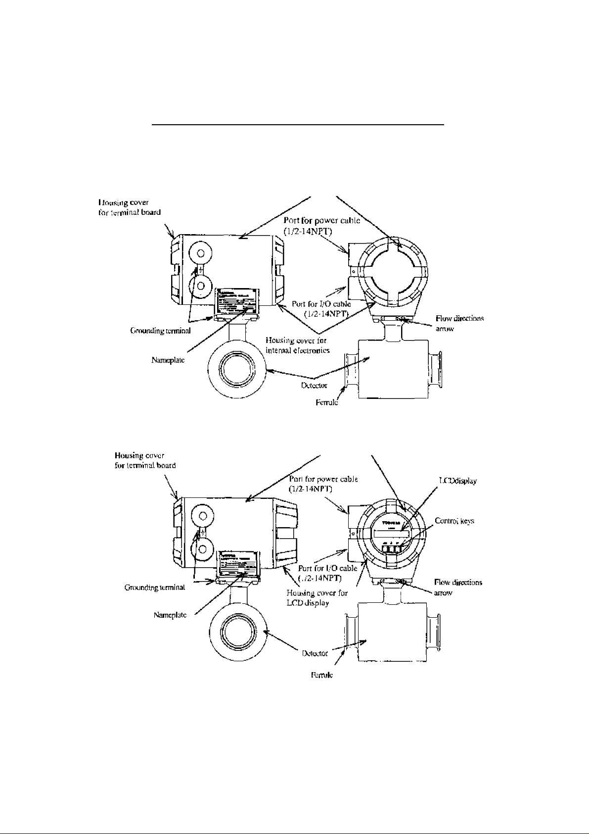
3. Names of Parts
The oulline drawing of the LF4y4/LF404 flowmeter is shown in Figure 3.1 and (lie in*
_____________
IMPORTANT
The apparatus should not be provided with the cable glands^
Please prepare yourself for the cable glands which could be used in Division2 hazardous locations.
icrnal views of tJie I.F404 converter arc shown in Fifinres 3.2 and 3,3,
____________
6F8A0774
Outline ]>ra>i^ing
Converter
LF494/LF404 withaiit LCDdispliiy(standarcl)
Convcrlcr
LF494/I J*'404with IXD display (optiimal)
Figure 3,1 OutliDe drawing of LF494/LF404 Flowmeter
- II -
Page 13

TOSHIBA
Tennina] Board of O^'404 Converter
6F8A07.74
Power supply LcrmijjLils
Digital output (DOl) D02)
tcrminalu
Internal grounding terminal
External groondini*
^ terminal
Digital input (Ur) terminal
Common for Dl, DOl and 1X)2
Figure 3*2 Teminnl Bt>ard of LF404 Converter
Current output terminal
- »2 -
Page 14

TOSHIBA
Contrri switch or kej's of LF404 Converter
6F8A0774
LF404 without LCD Dtsplay
Figure 3J Control switch or keys of LF404 Converter
-
13
-
Page 15

TOSHIBA
4. Installntion
Safety Precautions For Installation
I
Do not live ciremts under envTonmcni of explosive atmospheres.
6F8A0 7 7.4
A WARNING
(S)
DONT
M Do not use parts of other products.
O
DOMT
f Do not live circuits While assembly of all components is not over.
0
DONT
I Install per the National Electrical Code for the US (NEC, ANSI/NFPA 70)
and the Canadian Electrical code for Canada (CEC, CAN/CSA-C22J)«
O
DO
Live part of electric circuit or a high temperature department can
cause explosion.
Protective performance degradation for hazardous location can
cause explosion.
Protective performance degradation for hazardous location can
cause explosion.
Unsuitable conduit connections for hazardous iocation can cause
explosion.
A CAUTION
■ install a switch and fuse to isolate
the LF494/L.F404 from main power.
Power supply from main
power can cause electric
shuck or circuit
QQ breakdown.
■ Use an appropriate device to carry and
install the LF494/LF404.
If his product falls to the
grou nd, i nj u ry, or
malfiincrioji of or damage (o
[jQ the product, can he caused.
■ Do m>t modify or disassemble the
LF494/LF404 unnecessarily,
Modifying or
disassembling this product
vHy cause electric shock
m a If un ction or d am age to
DON’T product
■ Do not work on piping and wiring
with wet hands.
Wet hands may result in
electric shock
DONT
-
14
■ Ground the LF494/LF4(M
Independently from power equipment.
Operating this product without
grounding can cause electric
Q0 shock or malfunction.
The label shown left is placed
near the terminal hoard for
power input,
/ J \ (A black border and symbol on
yellow triangle)
Re alcri to electric shock.
-
Page 16

TOSHIBA
4A Location
6F8A0774
To Kcicct the inslaUatioii site, follow the prccaations described below:
■ Avoid places where fluid runs in a pulsating torm,
■ Avoid plaees wiihjji the immediate proximiiy of equipment producing electrical
interference (such as motors, transformers, radio transmitters, electrolytic cells, or
oiher equipment causing electromagnetic or electrostatic interference),
■ Avoid places where excessive pipe vibration occurs,
■ Avoid places where there is direct sunlight. If this is unavoidable, use an appropriate
shade
■ Avoid places w'here corrosive atmospheres or Jiigh humidity conditions obtain,
■ Avoid places of loo great an elevation or constricted areas where clearance
for installation or maintenance work is not provided,
■ Design piping so that the detector pipe is always filled with fluid, whether the fluid is
flowing or not,
■ The LF494 detector has no adjustable piping mechanism, Insiall an adjustable short
pipe where needed.
■ Chemical injections should be conducted on the dow-nstream side of the flowmeter
15
-
Page 17

TOSHIBA
4.2 Mounting Procedure
6F8A0774
A CAUTION
■ Use an appropriate device to eatry
and inistall the LF494/LF404. working on pipes.
If his product falls lo the
A B ground, injury, of power is applied can
malfunciioit of or damage
DO to the product, can be
caused.
4.2.1 Pipe checks
Before insiaJling pipes, check for iiny leaning ns illustrated in Figure 4.1. An attempt to
unreasonably connecting pipes that arc inclined may lead to a detector breakdown or
tlnid leakage. Connecting pipes in an eccentric state may also cause local wears and leans
of linings, as well as measurement errors.
Before installing pipes, make sure lo flash the iiiierior of the pipes to remove deposited
matters.
■ Turnoff mains power before
Working on pipes while
V_y cause electric shock.
DON’T
- 16 -
Page 18
TOSHIBA
4,2,2 Installation Procedure
6F8A0774
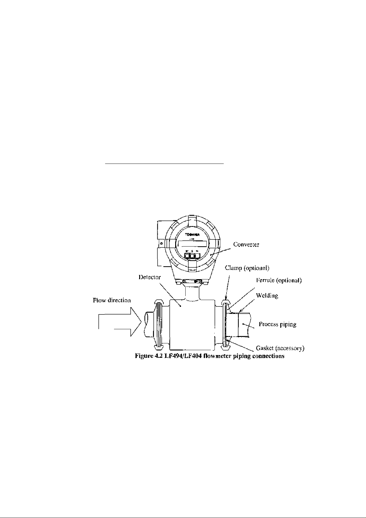
The LF4y4/LF404 adopis the ISO ^^^52 ditmp connection mcihcnJTo mount the 1.F494/LF404, see Figure 4.2 and follow the procedure below;
1. Weld a ferrule of the detector to the proces.s pipe on both upstream and downstream
sides.
2. Install the LJ’494/LI-404 between the two tcrrulcs w'hicli were welded to the pnjcess
pipes above.
3. InstaU a gasket betw^een ;he grooves of theferruJeon the detector side and lhal of the
ferrule on the process pipe for both upstream and dow^nslream sides, 1 iicn place a
clamp over the joined ferrules as shown in I’igure 4,2 and tigliien with the screw' for
both upstream and downstream process pipes.
IMPORTANT
When high-temperature fluid is being nieasuredj radiant heal from ihe detector pipe surface and
adjoining pipes may cause the ambient temperature of the converter to go above 60 °C. If the
ambient tempera lure goes above 60^ C, (ry to lower the temperature by measures such as wrap
ping hcal-insulating materials over the detector pipe and adjoining pipes.
_______________________________
- 17 -
Page 19
TOSHIBA
4J Piping Connections
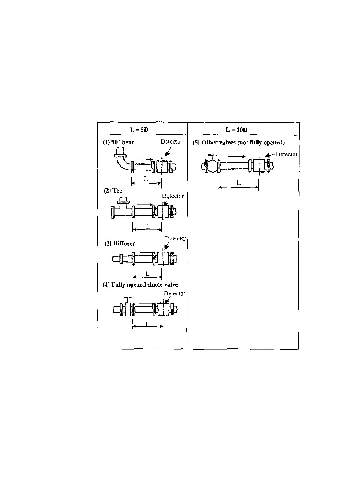
(1) Required Pipe Length
6F8A0774
If various jaintsS ¡irc used upiitream of the cleiector oullot, the straight pipe length us
shown in Table 4J is required.
Table 4.1 Required straight pipe length on the upstream side
L: Required straight pipe ietiglh—straight pipe length plus half length of the detector.
D: Nominal bore size (diameter)
NOTES
1. The length of a reducer* if connected, can be counted as a part of the straight pipe
length.
2. No straight pipe letiglh is needed on the downstream side, if a butterfly valve is
installed downstream of the detector, do not let the valve plate protrude into the
pipe of the detector
- U -
Page 20

TOSHtBA
6F8A0774
C2) PipÊ Orientation
The detector may be installed in horizontal, vertical or sloping pipe runs as shown in
Figure 4,3, However, cxccpl for horizontal installation, llmd should flow from lower to
upper directions. See Figure 4.3.
r~
Fldw direction
I
I^Cb)
(a) Horizontal pipe instailation
(h) Vertical pipe installation
(c) Sloping pipe insialiation
Ground sgriace
Figure 43 Detector Piping Orientation
The electrodes should be positioned horizontally against the ground surface in any piping
installation. See Figure 4.4.
(Jmss-scdiiin A - A
Figure 4.4 Installation position of the detector
-
19
-
Ground surface
Page 21

TOSHIBA
6F8A0774
(3) Flow Direction
Install the delector in accordance with the flow direction arrow on the detector. See I’ignre 4,5.
If the actual flow runs opposite to the specified flow direction, the following display and
output appears.. (For bidirectional multi-range measurement, sec 103^ “Mulli-rangc
Functions/’).
* LCD display (optional)« Instantaneous How rate—indicates negative values»
Totalized flow—no a>unts added,
* Output:Current output—4.0 mA output; Pulse output—No pulses
For bidirectional range measuremenu the flow in opposite direction results in a positive
output value. See 10.3» “Multi-range Functions/’
(4) Preventing sin Empty Pipe Condition
Design an upright pipe run (Figure 4.6) or sufficicjit head pressure (Fig, 4.7) at the
downstream detector oullet if there is a possibility of the detector pipe becoming emptied.
Upright pipe run
Figure 4«6 Detector with 3n upright pipe run at dow'ustream outlet
Detector
Z
Figure 4.7 Detector with sufficient head pressure at downstream outlet
- 20 -
Page 22
TOSHIBA
6.F8A0774
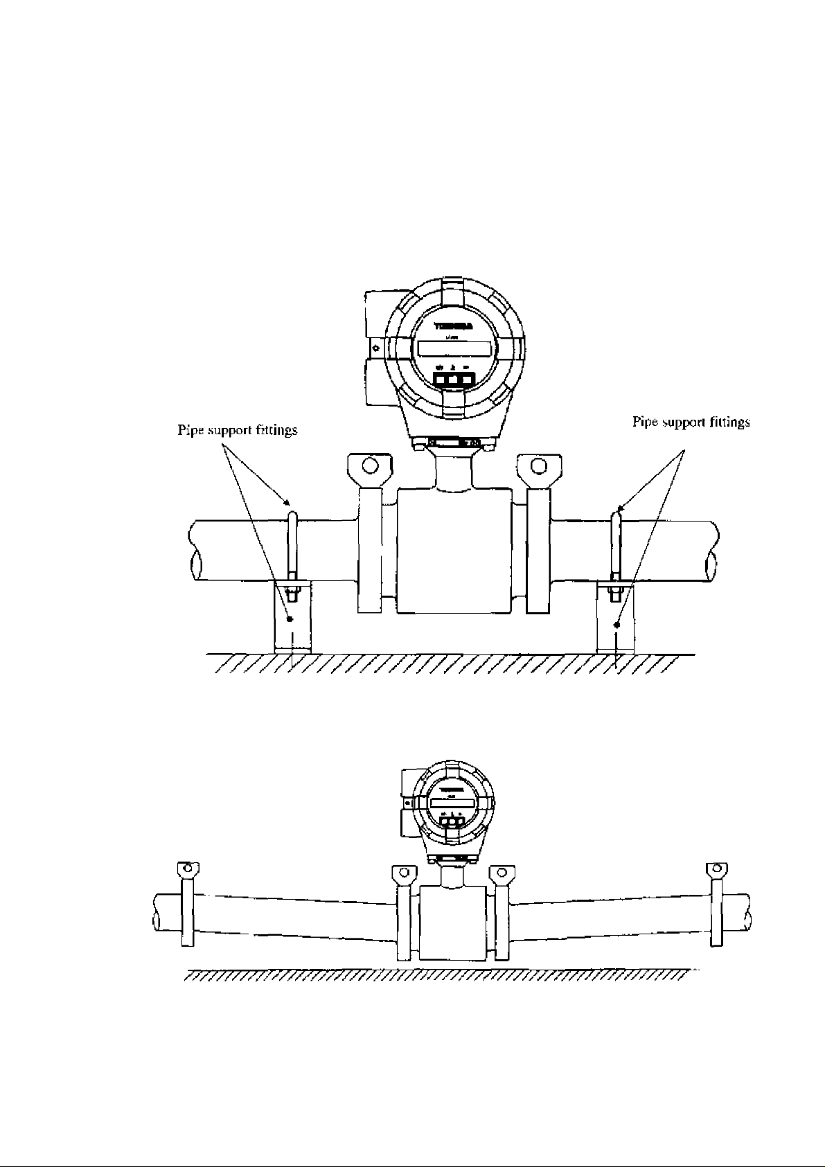
(5) Supporting Pipe
Fix Ihc relevant pipes installed on both sides of the detector by attach fittings, etc. to support
the pipe. Y iy supporting the pipes, not only the pipe vibration is reduced but also the damage
to the pipes by the electromagnetic flowmeter's weight and the fluid mass. And it protect
from fluid leakage at flange face (see Figures 4.^ and 4.9).
Figure 4,8 Example of Pipe Fixing Procedure
Figure 4,9 Model Diagram of L'nsupported Pipes
- 21 -
Page 23

TOSHIBA
6F8A07.74
(6)Groiindirif<
The grounding terminal of the LF494/LK404 Qo’ameter should be grounded with lOUohm
or less ground resistance. Use a heavy copper braid or wire (cross-sectional area 5,5 nun"
minimum) to ground the lerminal and make it as short as possible. The terminal is M4 siiic
and an M4-siiie crimped ring fug should be used to connect the wire to the terminal. Avoid a
common ground where earth currcni may fliw. An independent ground is preferable, See
Figure 4.1(1.
To prevent a iwo-poini grounding, ground the shielded cable on the receiving instrument
side,
Figure 4.10 Grounding Procedure
- 22 -
Page 24

TOSHIBA
5, Wiring
6F8A0774
Ж WARNING
DO NOT DISCONNECT WHILE CIRCLIT LS LIVE UNLESS
LOCATION IS KNOWN TO BE NONHAZARDOUS*
(S)
DON’T
Do not live circuits While assembly of all components is not over.
0
DON’T
I Install p«r the National Electrical Code for the US (NEC, ANSl/NFPA 70)
and the Canadian Electrical code for Canada (CEC, CAN/CSA-C22J)*
О
DO
Live part of electric circuit or ^ high temperature department cun
cause explosion.
Protective performance degradation for ha2ardou,s location can
cause explosion.
Unsuitable conduit connections for hazardous location ctm cause
explosion.
Ж CAUTION
■ Do not work on piping and wiring
with wet hands.
Wei hands can cause system
failure,
DON’T
■ Do nut modify or disassemble the
LF494/LF404 unnecessarily.
Modifying or disassembling
1 jj^ this product can cause elcc-
trie shock, malfunction of or
DON’T damage to this produci.
■ Use the proper cables for wiring of
power and I/O .
Using a cable other :han the
уЛ one specified may c^usc sys-
/ J \ tern failure or damage and
may break watcrproul.
Ш Ground the IvF494/LF404 properly*
Operating this product without
a grounding can cau^e system
malfunction.
DO
■ Prepare yourself for the cable glands
which could be used in Division 2
hazardous Incation.s*
The apparatus should not be
provided with the cable glands.
DO
* The label shown left is placed
Л\ near the terminal board for
/ power input.
" * Be alert to electric shock.
- 23 -
Page 25

TOSHIBA
6F8A0774
I'lowmeter acuumcy may be affccieJ by the way wiring is executed. Proceed with wiring
taking ihc foJIowiJig prccauiions:
(1) Select the cable runs away from electrical equipment (motors, transformers, or
nidio transmitters) which causes electromagnetic or electrostatic interference.
(2) Deteriorarion of fJowmetcr circuit insulation occurs if the converter interior or
cable ends gel w^et or humidified. 'I’his in turn causes malfunction of flowmeter
or noise problems, Avoid a rainy day if the flowmeter is to be installed outdoors,
l-ven indoors, prevent w^ater from splashing over the flowmeter. Try to finish the
W'iring as quickly as possibJe
(3) The converter has a surge-ai>sorbing barrier installed inside. Therefore, do not
conduct a wdthsiand voltage test for Ihe converter. To check ihe insulation of the
converter, use a voltage of 250 V dc or le.ss.
-
24
-
Page 26

TOSHIBA
5.1 Cables
Use the kind of cables shown in Table 5.1 to vsdre the converter.
Nnme
Power cable
I/O cable The number of wires for the output cable depends on the
Notei Use a four-wire cable if the arresters are to be used. See Figure 5.1 below.
5*2 EtKlernal Device Connections and Grounding
The terminal board comieciion;s of ihe 1T494/LF404 flowmeter are shown in Figure 5.1.
Proceed with wiring as described in Section 5.4, “Wiring Procedure."’
Cable type
Three-wire sheathed
cable (Note)
system specifications. Use a shielded cable with nominaJ
cross-sectional area of 1.25 mm^ and overall diameter of
11 to 15 mm.
Table 5*1 Cables
Nominal
cross-sectional
area
2 mm^
6F8A0774
Overall diameter
11 to 15 mm
If power supply is specified as DC, use LI ds positive (+) and L2 as negative (-) terminals.
Instrument Panel:
ordered separately
Currentoulput (4-20mAde)
Flowmeter
(■*■) Hs)
I LI I l^|FGt|l3tc|[cq*4 rn|noa|DQl| " f ^ I
T
______
^
..................
_____________________
I - ground resistant’^
! ***^ Grounded with 1 OOtior less
. V L>jgita] Output 1
: > ragiu^ O^rtput 2
‘ > Digital Input (20 lo 30 V dc)
1 -
IV wire
5,5mnr
or more
I/O cable
■7:^
W >wcr cable
^ '
' \
Power Switch
*1 To use the arresters, ground the GNI) terminal using the wire shown in broken line.
*2 Locale an cxiernal double-pole power switch on the powder line near the flow'meicr and within easy
operation. Mark one the switch as the disconnecting device for the flowmeter,
Use an appropriate swiicli of the rating shown below:
Recommended sw'ilch rating; Rating 250 V ac, fiA or more
Inrush current 15 A or more
— > pQWCï Supply
Figure 5*1 Terminal Block Connections
-
25
-
Page 27

TOSHIBA
6F8A07 74
IMPORTANT
(1) The grounding terminal of the LF494/UH04 flo^mEtcr should be grounded with
100 ohm or less ground resiiilance. Use a heavy copper braid or wire
(cross-seciioniil area 5 .5 mn:" minimum) to ground the terminal and make it as
short as possible. The icnninal is M4 size and an M4-sizc crimped ring lug should
be used lo connect the wire to the tenninaU Avoid a common ground where earth
current may flow . An independent ground is preferable^ See Figure
conductive pipeline grounding and noii-conducrive pipeline grounding procedures.
(2) To prevent a wo-poinl grounding, ground the shielded cable on the receiving
inshiimenl side.
5.2 . for a
I If connection pipe is conductive:
Connect between the grounding terminal
and both ends of the mating flanges with
a heavy copper braid or wire
(cross-section 5.5 min‘ minimum).
If connection pipe is non-conductive:
Use a heavy copper braid or wire
(cross-scciiiin 5.5 mm^ minimum) to
ground he terminal with UK) ohm or
less ground resistance*
Figure 5.2 Grounding Procedure
- 26 -
Page 28
TOSHIBA
53 Digital I/O Connections
Digital I/O icrmmEils cottsiM ol conlact oulpul lerniiiials (jilatidard DOl Eind optional
D02), voJlage signal input terminal (Dl, opcioiial), and signal common terminal {COM).
Hach terminal (DOl, D02 and DI) is isolated from internal circuits. Terminal (COM) is
the signal common for the other three terminals {DOl, DOl and DI).
Functions can be assigned for each xnninal with Ihe LCD control keys (option). See
Chapter 10, ‘‘Digital I/O Functions/
To connect an electromagnetic relay ot counter lo the contact output tcrrtiinal (DOl or 1>02)^
put a surge-absorbing diode into the input circuil of the relay or counter. See Figure 5.3 for
an example of electromagnetic counter connection,
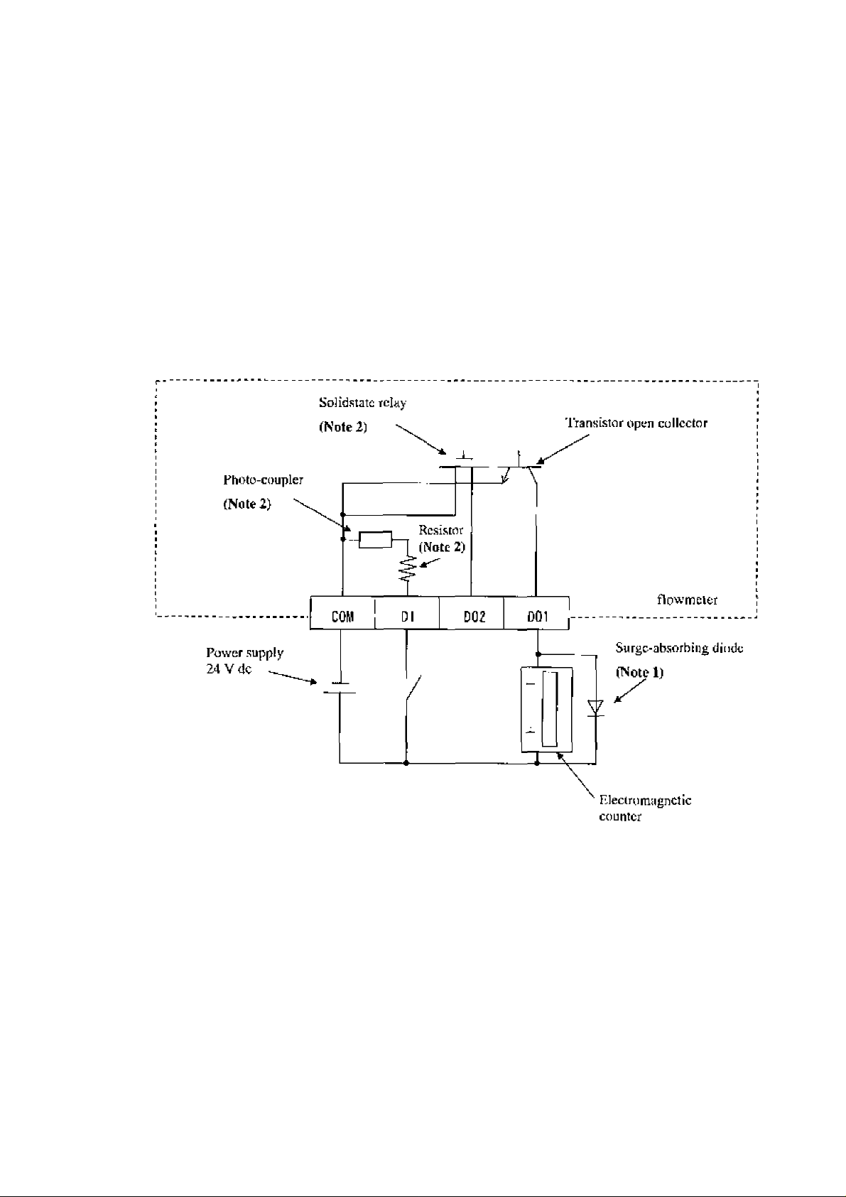
6F8A0774
Note I: Use a surge-absorbing diode of the rating: current rating lAand voltage rating
200 V minimum.
Note 2: The Solidstaie relay, photo-coupler and resistor are not provided for the standard
model (the one whth no digital I/O specifications). l.eavc the terminals for D02 and
Dl open.
Figure 5.3 Electromagnetic Counter Connection Exntnple
- 27 -
Page 29
TOSHIBA
S.4 Wiring Procedure
5A1 Cable Terminationi
6F8A0774
Cable termination and cable connections are described below.
A CAUTION
■ Ho not con d net w i ri n g work wt e n ■ Eto not w'ork on piping and wiring
power is applied.
Wiring while power is ap-
1 plied can cause clccinc 1 electric shock.
shock.
DONT DONT
IMPORTANT
Ttic apparatus should not be provided with the cable glands.
Please prepare yourself for the cable glands which could be used in Division2 hazardous
locations.
with wet hands.
Wet hands may result in
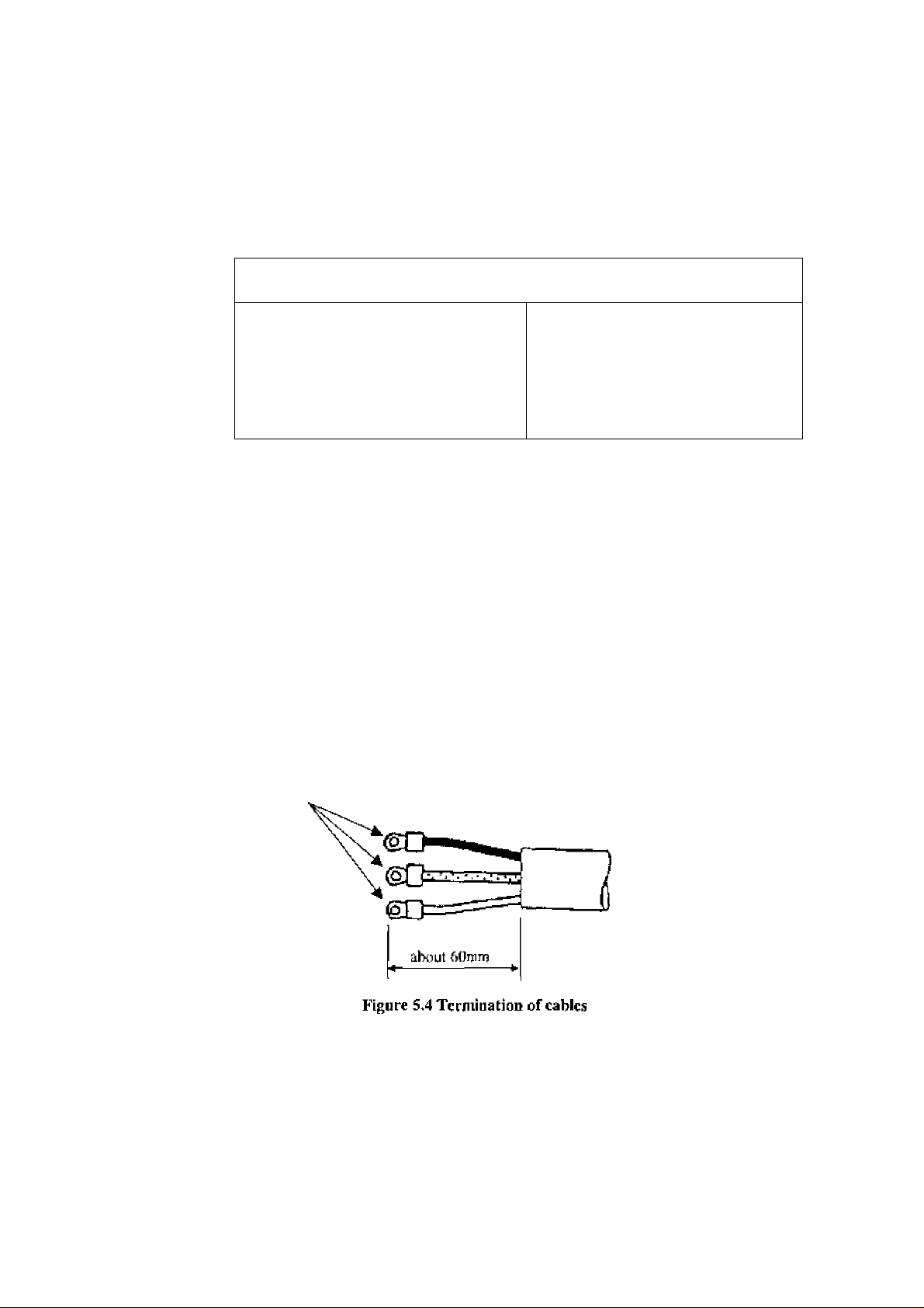
Use cables as specified in Table 5.1 ^ First, Remove the cable sheath about 70 mm from the
end to expose the coated wires and then strip the wires about 10 [nm. Then attach an
M4-sis:e compression terminal lug to the end of each wire using a compression tool. The
compression terminal should be of Ihe kind with insulated sleeve to prevent shorts between
adjacent terminals. The overall length oi thc wire with the terminal attached should be about
6(.) nmi. Sec Figure .‘5,4 below,
M4-sizc compression terminal lug
- 28 -
Page 30
TOSHIBA
5A2 Cable Connections
6F8A0774
Connect the term incited cable wires to the terminal board as described below.
IMPORTANT
Connect the wires securely to :hc terminal board. A loose connection may result in
unsaiisfacLory flowmeter performance. Make sure the wires arc securely connected.
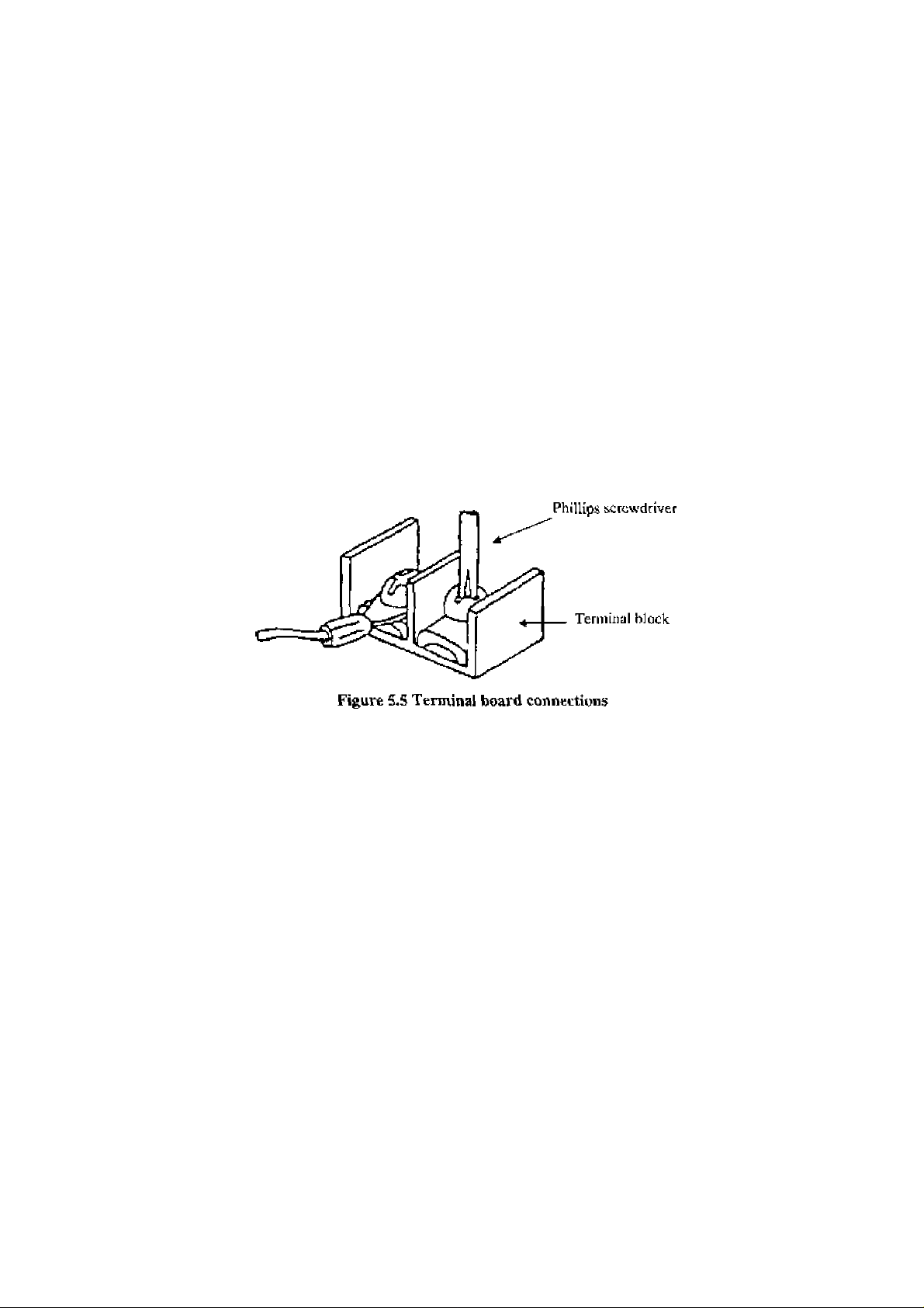
(J) Remove the housing cover for the terminal board shown in Figure 3.1. The terminal board
is located inside the converter as shown in Figure 3,2. Connect the crimped terminal of
each wire to the specified pin of the terminal board . See Figure 5.1 for the terminal board
configuration, Tighten each crimped terminal to the terminal board wiih a screw using a
l*hil!ips screwdriver as shown in Figure 5.6. Loose connection may result in unsatisfactory
flowmeter performance. Make sure the wire is securely connected.
NOTE
ITic appropriate torque for tightening the terminal board screws is J .2 Ntn (12 kgf- cm).
(2) After the terminal block connecriorij pull the cable a little so that the cable runs straight
from (he terminal block without unnecessary winding.
(3) Attach the terminal cover and screw the housing cover for the terminal block. To keep the
housing seal, lighten securely the cover using a tool fitting with the groove on the cover
- 2& -
Page 31

TOSHIBA
6. Operation
6F8A0774
A CAUTION
Do not touch the LF494/LF404 main body when
high temperature fluid i.s beii^ measured.
Thc fluid raises the main
Q
DONT
6*1 Preparatory cheek
Follow the procedure described below to prepare before starting the (low tneasurerrienl.
System Check
Check the wiring between the converter and related instruments.
Make sure all Ihc bolts of connection flanges on which the flowmeter is mounted
securdy tightened.
body tempera lure and can
cause burns when touched.
Make sure the direction of flow arrow is in accordance with actual flow.
Make sure the flowmeter is grounded with IDO ohm or less ground resistance.
Make sure the converter housing covers are securely tightened.
Placing System On-Stream
l.ct the fluid go through the delector pipe. When the detector is filled with the
fluid, stop the fluid and keep it still in Ihc detector pipe.
Supplying Electric Power
Make sure the powder supply is as specified.
Checking Converter Parameters
Check the configuration parameter settings, Refer to Chapter 7, "LCD Display
and Controls,” Chapter 8, “Configuration Parameter Selling/’ and Chapter 11,
“Communications Function/'
Zero Adjustment
Wail for 30 minutes to warm up the flowmeter, 1 hen making sure the fluid holds
still in the detector pipe, starts the zero adjustment.
Refer to 6,2, “Zero Adjustment.’"
On line measurement
After checking the items and conducting the ze ro adjustment as listed above, let the fluid go
through the detector pipe. Output (4-20 mA dc) directly proportional to the flow rale can be
obtained.
30 -
Page 32

TOSHIBA
6F8A0774.
62 Zero Adjustment
To conduct zero adjustment of the flowmeter, the fluid in ihc detector pipe must be held stilL
There are three different ways to start the ^ero adjusimeni:
(1) I^essingthe zero adjustment switch for the model without IX^D display
(2) Pressing a combination of control keys for the model with LCD display
(sec 8.2.8, ‘Zero Adjustment ’)
(2) Sending a command signal from a HAR'l’ communications device
(such as the AFIOO hand-held terminal).
The follow'ing is the procedure for starting the zero adjustment for the model without LCD
display.
■ J’ress the zero adjustment switch for more than 3 seconds.
(Note [hat once the zero adjustment is started, there is no way to caitceJ the zero
adjuslmem sequence.)
Then the LHD indicator lights and [he zero adjustment sequence will start. 1 he zero
adjustment sequence lasts about 3 to 6 seconds. (Zero adjusimcrit duration depends on
the excitation current frequency. Jl lakes about 3 seconds for 24 Hz setting and about 6
seconds for 12 Hz and 6 Hz settings.)
When the zero adjustment sequence ends, the LliD indicator goes off.
To conduct the zero adjustment, it is necessary to open the converter housing cover for
inicmaJ electronics and press the switch. Observe the following precautions when you
open the hou.sittg cover:
(1) Do not open the cover in the open air unprotected against rain or wind.
It you adjvist the ilowiucier in the rain, this can cau^e electric shock or damage to the
flowmeicr electronics. If wind blows against the internal circuitry of the converter, output
may fluctuate and fail to indicate correct measuring values.
(2) l>o not conduct the zero adjustment when the amhieni humidity is high, By opening the
cover in high humidity conditions, the measuring accuracy may he reduced or damage
caused to the flowmeter electronics.
- 31
Page 33

TOSHIBA
1, LCD Display and Controls (option)
You can select the operation modCj change the configuration pariinictcrs or cxeculc
operation-specific functions using the control keys on the panel. How to operate these
keys is described in this chapter.
7.1 Outline
The LF404 Converter has an optional LCD display. The LCD display can be used to set and
indicate various configuration parameters, Figure 7.1 shows the front view of LCD display.
(1) Do not open the housing cover for LCD display in the open air unprotected against rain or
wind. If you open the housing cover for LCD display in the rain, ii can cause electric
shock or damage to the flowmeter electronics. If wind blows against ihc internal circuitry
of the converter, the output may fluctuate and fails to indicate correct measuring values.
(2) Du not open the housing cover for LCD display w'hen the ambient humidity is higli.
I3y opening The cover in high huraidity conditions, the measuring accuracy may be re
duced or damage caused to the flewmeiei electronics,
6F8A0774
Housing cover for
'^LCD display
Figure 7.1 LF404 Converter with LCD display
LCD display
A 2-linc X 16-character liquid crystal display. 1 he backlit display enables an easy-to-read
indication even under poor lighting conditions. Instantaneous flow rates or totalized How in
the measurement mode, or configuration parameters in the setling mode can be displayed.
- 32 -
Page 34

TOSHIBA
6F8A0774
■ Control Keys
Changing the operation mode, checking or changing parameters can be done with these keys.
To operate these keys, you have to open the converter housing cover. Observe the following
precautions when you open the housing cover:
rnnetions of each control key when pressed are shown in the table l>clow.
Control keys
SET
□
Basic functions of control keys
Oocs into the iteins sdeetion aeijucTice.
K, 00 n/s
lit). 0 Ï
Ones into the dct^Mcel-ltcni specifying sequence for each selcctetl iicin in
measarement, setting or calihralion modes.
Al :£i, CJRR.
1—\
'
-------
Al'.EX. CUftR
/
.selection sequence
A1:EX. CURB,
0
selection sequence
Stores the sclcct2:<j Juta in the setting mode.
Bl:UfllT 1
%
status of chairging the data
Changes itenrs (alphabet letter and number) in the items selection sequence,
and changes parameters (numbers andi'or units) in the detailed-item specifying
sequence in measurcnient« selling nr calibration nnodes.
C2:RA^G£ 1
02. 000 in/s
r—N
date;[J,2UUOm/s
Starts and stops the totali/er in the incasurement mode.
F lOCO
100.0 %
step the totali/cr
Changes digits (alphabet letter and number) in the items selection sequence,
and starts the detailed-item specifying sequence by indicating the left-most
digit with the cursor
D1: DAMPING
_______
,
-----
w
\
00 s s
setting mode siaitjs of finish changing
Moves the cursor frocn Ictl Iti right (from the right end reverts to the left end) in
measurement mode
B1 :UNIT 1
%
Status of finish changing
C?:RANGE 1
03. OOO ñ/%
darctoOOOm/s
(Note)
F
tool ID' C
1ÛR. 0 %
start the totalizer
D1 : DAHPINO
00. 5 S
►
□
Resets the iotaligcr in the measurenient cnodc. (Nutgl
Note: To operate the totalizer, it is preterabk U> set the indicating unit (UNIT I and/or UNIT 2)
to one of the units appropriate for totalization just to make sure it is operating eorreclly.
See 10.2, "Totalizer and Pulse Output/'
Gl : COUNT RATE
1. 23£-4
Indicate cursor un^er ‘ I ’
F '000 C
00. 0 1£
start the tiitaiizer
- 33 -
1—A
*
—/
1
----
1—/
Cl: COUNT SATE
[. 23E-4 m’
Indicate cursor under
0 m*
F
\
TOO 0 X
reset the totalizer
c
Page 35

TOSHIBA
7.2 Display Format
6 F8 AO 7 7.4
In ihe me-isurcment mode» measured data are displayed in UNIT 1 (primary indioaling unit)
and UNIT 2 (secondary indicating unit). As to indicating units, see 8.2,4, ‘"Indicating Unit '’
Display Format
DisSplayed in UNIT 1 indicating unit.
I— *‘C ' indicated when lotfd tlow is cc>unted.
IF 10 0 0 0 0
10 0.0 %
____________-¿L.
M Measured Value Display Format
(1) Flow rate
_
___
Upper 4 digits maximum arc cTfcctive (for the selected span).
r
")
“ C ’’ is indicated when
communication is in progress.
I b t
I C
L _ - .
Displayed in UNIT 2 indicating unit.
'The unit of time
-The unit of flow
‘7 digits (9999999) maximum including decimal
point
'Flow direction: Forward “ (blank space);
Reverse “
-
34
-
Page 36

TOSHIBA
(2) Totiìlizer
F 9 9 9 9 9 9 9 S C
I I I I- ..............................................................
(3) Volumetric flow
F 9 9 9 . 9 9 ml
I J I.......................................
.....
I
LJ
6F8A0774
L- “C” is indtcaietj when (oial tlow in counted
Increments per cnunling rale, Refer (o
8.2.10, '"Counting Rate/’
Wrapfi iirounci after 99yy9y99.
“F’ for forward and “R" for reverac direction ilow
will be displayed
Displays down [o the smallest digit of counting rale.
J_
^ "'C” is indicated when volumetric flow is counted.
— The unit of flow
N) % display
-10 0.0 %
..................................................
.....
1 1 J
-
--------
8 digits (999^9^99) maximum including decimal
point
If (he flow count exceeds 999 99 9 99 , wraps around.
"F" for forward and “R” for reverse direciion
flow will displayed.
Displayed dowm to i).l %.
Displays up to 125.0 %.
— Plow direction: Fomard " “ (blank space);
Reverse
- 3i
Page 37

TOSHIBA
6F8A0774
13 Itasic operations
How measurement in the mcasuicinent mode, checking or changing configuration
parameters in the setting mode and a converter unit check in the calibration mode arc
the basic operations of the LF404 converter
7J,1 Mode Change
The Lr404 converter has three operation modes: measurement, setting and calibration.
The system stays in the measurement mode after the power is turned on. To change the
mode to the selling or calibration mode, press [SET] and select the desired item using
( ► ] and [ A. ] keys. To return to the measurement mode, scJect “tP (MliASURH
MODE) for the number column of configuration items (such as AO or BO), Sec 7.4,
“Configuration Items Selection Table.”
■ Measurement mode
: measures the process flow and displays and outputs the measured process values, The
flowmeter can measure the flow velocity, flow rates, or totalised How, The flowmeter
first goes into this mode when power is turned on.
Setting mode
r used Lo check or change various configuration parameters used in the measurement
mode. These parameter values are displayed while checking or changing these values
hut the flowmeter outputs the measured process values as in the measurement mode.
See 7.4, "Configuration items Selection Table” and S.2, “Checking or Changing
Parameters” for details. Configuration items are from A1, A2, A3 to Ml.
Cnlibration mode
: used to check the converter internal circuits. The intemally generated simulation signal
is used to check the measurin| span and excitation current value. The current output of
the flowmeter changes in accordance with the simulation signal. The status of each
digital output is held to the value just before the .system moved into the calibration
mode. See 7,4, ^'Configuration Items Selection Table” and Chapter 9, “Calibration” for
details. Configuration items are from M lo N4,
-
36
-
Page 38

TOSHIBA
Change mode flow
SET A ^
□ □□ arc sJiown tQ control keys, anti LF404 display is changed lo
6F8A0774
------------
Measurement mode
^ indicaied.
-
37
-
Page 39

TOSHIBA
6F8A0.7.7 4
7.3.2 ConflguriitioTi Parameter Selecticin in Setting and Calibration Modes
Process as follows lo select the desired items, to chock or change the item setting value,
■ To selticts the desired item :
Key operation
SET
□
▲
□
►
□
□□
Display example Description
10. 00 rci/s
Measure value displays.(Mcasurcmcnto mode)
100. 0 %
Al: EX. CURR,
Bl; UNIT!
Bl; UNIT!
C2; RANGE 1
Pressing [SILT], the system changes to the items
selection sequence. (Note)
And the cursor appears under alphabet (A),
Change the alphabet to ''E” by pressing [ ^ ].
* If cursor is tile number, the number is increased
by pressing [a ].
Then move the cursor (o the number by pressing
[ ► ]
* If cursor is the number, the cursor is
changed to the alphabet by pressing f ► ],
Selects the desired item (indicated by an
alphabet letter and a number) first by selecting
llie digit (alphabet or number) with [ ► ] and
then changing the value with ( a ].
The example shows “C2: RANGE V’
Note: In case of that the convrtcr is type for special specifications and seitcd password^
changing measurement mode to items selection sequence, password-input mode appears.
See 7,5"Password Ltput ‘for details about Password-input mode
Sec 7,3.3 ’’Converter for Special spccifications”for to differentiate the converter for
special specifications and normal.
- 33 -
Page 40

TOSHIBA
6F8A0774
To change the setting value:
Key operation
^ ►
□ □
SKY
□
□
: □
►
□
Display example Description
Items selection sequence displays.
C?: RAWGE 1
Selects the desired item (indicated by an
alphabet letter and a number) first by selecting the
digit (alphabet or number) with [ ► ] and then
changing the value w'ith [▲ j.The example shows
“C2:RANGE 1 '
Press [SET] to vSelect the desired item setting
C2; RANGE 1
02. 000 n/s
value. And the cursor disappears and the item
setting value displays.
You can check it.
C2: RANGE 1
02. 000 m/s
C2; RANGE 1
¡2. 000 m/s
C2: RANGE 1
12. 000 m/s
Pressing [ ► ), the cursor appears.
Parameter changing sequence
Change the value by pressing ].
Then move the cursor to another digit by pressing
[ ► 1-
Change the value by pressing Then move
□ □
▲ ►
C2: RANGE 1
05. 000 m/s
the CLirsor to another digit by pressing [ ► j and
change the value.
In This example repeal (his prercess tmiil the
display shows "'05. ODOm/s
5ET
C2: RANGE 1
05. 000 m/s
▲
C2: RANGE 1
02. OOO m/s
i
S\:y
C2: RANGE 1
05. 000 m/s
□
Бу pressig [SET], flickers the selected value to
confirm changes made for the selected item.
By pressing [-^1» to return to the parameter
changing sequence.
By pressing [SE'l 1, stores the indicated value and
Slop flickering of data.
-
39
-
Page 41

TOSHIBA
6F8A0774
To return the measurement value:
Key operation Display exampJe Description
SET
□
i
►
□
▲
□
□ □
C2: RANGE 1
0. 5000 m/s
C2: RANGE 1
C2; RANGE 1
C3: RANGE 1
CO . MEAS. MODE
Checking the setting value or after setted the
value.
By pressing [Sii.T], return to the items selection
sequence.
Items selection sequence displays.
Then move Ihe cursor to the number bv pressing
[ ► ]
* If cursor is the number, the number is changed
to the alphabet by pressing [ ► ].
Change the alphabet to ‘‘B” by pressing [ a ].
** If cursor is the number, the number is
increased by pressing [ ^ ].
By pressing [ ► ] and [ A ], select
-0:MEAS, MODE"
Ttie example shows “CO: HEAS MODE'’
SET
□
10. 00 m/s
TOO. 0 %
- 40 -
Pressing [SE'r], returns to measurement mode.
Page 42

TOSHIBA
6F8A0774
7<3<3 Converter for Speciii) pacifications
The converter for special specifications is added some setting parameters. To
differentiate the converter for special specifications and normal, remove housing
cover for the tcrminii] txiard shown in Figure7.2. The converter marked as shown
in Figure 7.2 is for special specificationsj and non^marked is normal.
The added setting parameters are following items.
(1) Password input/scuing
(2) 4-20mA alarm out setting
(3) DI detective level setting
(4) Preset function
See 8.2, “Checking or Changing Parameters’' for details.
Hxample; F400 0113
Figure 7.2 LF404 Cotiveiter for special specifications
- 41 -
Page 43

TOSHIBA
7.4 Configuration Items (Selection Table
6F8A0774
In the setting and calibration modess configuration items can be selected as shown beJow. For
exampie, the excitation current can be selected by the item AJ, To change the parameters for
the selected items, see the following chapters. To return to the measurement mode, select "‘0”
for the number (such as AÜ).
Setting mode items (Al, A2, A3 to Ml): See Chapter 8, “Configuration Parameter Set ling. ’
Calibration mode item (N1 to N4): See Chapter 9, ^'Calibration.”
A n
B *1
c n
D M
E *1
F n
G
If
1
0
1
Kxeitatiun Cur*
rent *2
Indicating
Unit 1
Range T ype
*2
Damping
Constant
Zem
Adjust me 111
DOl Function
*2
Couniing Rale
*1
*2
PfCSCl Count
*2
High Alarm Set *2High Alarm
2
Meter Size
Indicating
Unit 2
Range ]
Low Cutoff
D02 Function
Pulse Widlh
Preset Punct
Value *2
*■2
3 4
Excitatioc Fre
quency *2
Range 2
"2
4-20 mA Aim.
Output '‘2
D[ Funciien
*2
•2
Low' A lam Set “2Low Alarm
"2
Password
Range 3
DOl Alarm
Active Set *2
Value *2
*2
5
Range 4
D02 Alarm
Active Set *2
*2
6
Range
Hysteresis *2
DI Det. Level
^2
J
K
L n
M n
N *1
Empty Pipe
*1
Alarm
*l
Rtite-ofehangc Limit
Fixed‘Value
Output *2
Zero Offset
Adjustment
Flow Rate
Cal *1
Control
Limit I’ime
Fixcd-currcnl
Output *2
Flow Rate
S\g5i)% "2
Fixed-pulse
Output *^2
Flow Rate
Cal H)n% ^2
Exciting
Current Check
*1: Returns to Ihe measurement mode.
"*2:Password-pro(ecied parameter
Note: “A4:Password”, ”n3:4-20Alm.Ou(\ "1’6:D[ Dcl,[x;vel \ and "H2:Freset Fund” are added
parameters in the converter for special specifications.
-
42
-
Page 44

TOSHfBA
7.5 Password Input
6F8A0774
Password input is ^ddcd parameters in the cenverier for special specifications {refer to
733 “Converter for Special specifieauons”). Only in case of the converter for special
specifications, read thisS section.
The converter for special specifications have the password ,That protects from calibrating and
changing part of parameter that influences mea.surement,.
Sec 7.4 ’Configuration Items Sclecticn Table’" for details of password-protected parameter.
See W.2,17 "'Password” for password selling.
^Setting 4IU0’ to [he password or Ihe normal ainverter (see 7.3.3 "Converter for Special
specifications"), password input mode does not appear and all configuration parameter
and calibrate can be changed,
■ To input password:
The following example shows how to input password ,123.
Key operatiort
Displsiy example
De$(cription
SET
□
▲
□
□ □
SET
SET
□
lO. 00 jn/s
IDO. 0 %
PASSWORD INPUT
DOO
PASSWORD INPUT
100
PASSWORD INPUT
m
120
123
PASSWORD INPUT
123
A1: EJ{. CURR.
Measure value displays.(Measuremento mode)
Pres^iing [SET], password input mode and the
cursor Eippears,
Change the value by pressing [ a. ],
Move the cursor to another digit by prc.ssing
f ► ] and change the value by premising [ a j.
In this example repeat this process until the dis
play shows "T23h"
Pressing [SET], the cursor disappears and the
changed display flickers. Press [SET] again to
input the value.
Whether input password agrees or dose not agree ,
the items selection sequence, "AT :EX. CURR” ap
pears.
Eui if input password docs not agree, you can not
change setting parameter and calibrate.
See 7.4 ’’Configuration Hems Selection Table” for
details.
- 43 -
Page 45

TOSHIBA
8. Configuratiim Parameter Setting
8»1 Configuration Items
To check or change parameters, first sdcci the desired configuration item as described in
7,3,2. The configuration items are Jisted below, Sec each section for detailed procedure.
6F8A0774
Section Configuration item
8.2.1
S.2 .2 Meter Size
8.2.3
8,2.4
8.2.5
8.2.6
8.2.7 Low Cutoff
8.2,8
8,2,9 Digital I/O
Excitation Current
Excitation Frequency
Indicating unit
Range Type
Span (range)
Hysteresis
Damping Constant
Zero Adiustment
8.2.tt> Couniing Rate
Pulse Width
8,2.11 Preset Count
8,2,12
8.2,13
8.2,14
8.2.15
8.2.16
8.2.17
8.2.18
8.2.19
8,2,20
High/Low Alarm
Alarm Limit Value
Empty Pipe Alarm
Ratc-of ehange Limit
Control Limit Time
Fixed‘Value OiKpul
Zero Offset Adjustment
Password *
4-20inA Alarm Output '*
DT detective Level
Preset Function *
Display example
Al: EX. CURR.
A2: meter SIZE
A3: EX. FREQ.
Bl: UNIT 1
Cl: RANGE TYPE
C2: RANGE 1
C
6; RANGE HYST
D1: DAMPING 05.0 s
D2: LOW CUT
El; ZERO ADJUST. 0. 1 %
FI; DOl FUNCT, 1: H ALM
Gl; COUNT RATE
G2: PLS. INIDTH
HI; PRESET COUNT
11: H. ALARM SET
12: H. ALARM VAL
Jl; EMPTY ALM
K1; LIMIT RATE
KZ: LIMIT TIME
Li: FIXED OUT
Ml: MANUAL ZERO -000 1 %
A4: PASSWORD 123
D3; 4-20 ALM. OUT 1 ;4. 0mA
F6; Dl DET LEVEL
H2: PRESET FUMCT
0. 2100 A
LSINGLE
01, 000 m/s
05. 0 %
05. 0 %
G. OOE-U
020 ms
00009000
flOO. Q %
0;OFF
05. 5 %
1 : H LEVEL
0:H0LD
50 m
24 Hz
ON
01 s
OFF
m/s
Page
45
47
49
51
55
63
65
67
68
71
74
76
79
82
85
89
91
95
97
99
"A4:Password^ ”D3:4-30ALM.OL T6;DI DP'rLEVHL", and ■H2:PRtiSHT
FUNCT'' arc added parameters in the converter for special specifications (refer to
7,3.3 ‘"Converter for Special specifications’'). The normal converter does not have
these selling parameters.
-
44
-
Page 46

TOSHIBA
8.2 Checking or Changing Parameters
6F8A0774
8.2.1 Excitation Current
Proceed üs follows to check or change ibe excitation current setting value.
■ To check the exciting current setting value:
Key operation
SET
□
SET
□
Display example
A1: EX. CURR.
0. ?100A
A1; EX. CURR.
Description
Press [SFT] first to start the items selection sequence
and select Air EX. CURR from among the
configuration items asing [ ► ] and [ a. ] keys.
Then press [SET] again to display the exciting
current setting value.
Pressing [SET], the system returns lo the items
selection sequence.
- 45 -
Page 47

TOSHIBA
IMPORTANT
The exciting currenl value h factory iset when shipped. Do nol change the value unless the value
dilTers from that wriiieii on tlie nameplate of the fiowmeter,
6F8A0774
■ To chitrige the excitation current iictting value:
I’he following example shows how' ro change the excitation current setting value
from 0.1900AIO 0.2150A,
Key openïlJun
SET
□
□
□□
SET
□
SET
□
Display example
A1: EX. CURH.
D. TgOOA
A1: EX. сияя.
0. 19Û0A
AT: EX. CURH,
0. 2900A
0. 2iOOA
0. 2150A
AT; £X. CURR,
0. 2T5DA
Al: EX. CURR.
Description
Press [SET] first to start the itemsS selection
sequence and select Al: EX. CDRR from among
the configuration items using [ ► ]and[A]keys.
Then press [SET] again to display the excitation
current setting value (0.1900 A in this example).
Pressing [ ► ], the cursor appears. 'I'hen press [ ► )
as many times as necessary' to move the cursor to the
digit to be changed.
Change the value by pressing [ a J, I’hcn move the
cursor to another digit by pressing [ ► ] and change
the value, In this example repeat this process until the
display shows “0.215ÜA.” (Note)
Pressing ]SET], the cursor disappears and the
changed display flickers. Press [SET] again to save
the value.
Pressing [SET], the system returns to the item.s
■¡election sequence.
Note: The valid range is from O.OfiOOA to 0.2300A. If you try to set the value altove
(].24tlOAj the error messsage * H. OVER SPhC appears. Set the value within the valid
range.
—
45
—
Page 48

TOSHIBA
6F8A0774
8.2,2 Meter Si^e
Proceed as folJows lo check or change the meter si7e of ihc cictecior.
■ To check Che meter size:
Key operation Display exjimple
SET
A2: METER SIZE
□
SET
A2: HETER SEZE
50 m
□
Description
Press [SET] first to start the items selection sequence
and select A2: METER SIZE from among the
cojifiguralitm items using [ ► ] and [ a ] keys Then
press [SET] again to display the current meter size.
Pressing [SET], the system returns to the iiems
selection sequence.
- A 7 -
Page 49

TOSHIBA
6F8A0774,
To change the meter ssize:
IMPORTANT
Meter sii^e iii 1 actory set when shipped. Do not change the meter size unless it differs
from the specified value.
The following example shows how lo change The meter size from 5f) mm to 100 mm.
Key operation
SET
□
□
▲
□
SET
□
SET
n
Display example
A2; METER SIZE
50 nur
M: METER SIZE
50 nut
AZ: METER SIZE
100 inin
KZ\ METER SIZE
100 mm
AZ: METER SIZE
Description
Press [SET| first to start the uems selection
sequence and select A2: METERSIZE from among
the configuration items using [ ► ]and[A]keys.
Press [SET] again to display the current meter size
fSO mm ill this e.xample).
Pressing [ ► ], the cursor apijcars.
Select "‘100 mm” by pressing [ a ] as many times
as necessary. (Note)
Pressing [SET], the cursor disappears and the changed
display flickers. Press [SET] again to save the value.
Pressing [SET], the system relurns to the items
selection sequence.
Note: The meter size is changed as shown below by pressing [ a ],
2.5 mm 15 mm “► 100 iiiin f^iXl mm —►0.1 in 0,5 in^4 in • 24 in
c:
Tf the meter size has been changed, other setting values (such as span and counting rate)
will be affected depending on the measuring unit u.sed. therefore, check those setting
values if you have changed the meter size,
- 43
□
Page 50

TOSHIBA
6F8A0774
8.2.3 Excitation Frequency
Proceed aii follows lo check or change the excitation frequency.
■ To check the excitation frequencyr
Key operation
SET
□
SET
n
t
___
1
Display example Description
Press [SEl’l first to start the items selection
A3: EX. FREQ.
24 Hz
A3: EX. FREQ.
sequence and select A3: EX. FREQ, from among
the coniigutation items using [ ► ] and [ ^ ]
keys. Then press [SET] again to display the
current excitation frequency.
Pressing [SET], the system returns to the items
selection sequence.
- 49 -
Page 51

TOSHIBA
6F8A0774
To change the excitation frequency:
The excitation frequency can be selected from f>, 12 and 24 Hz- T he characteristics of
the ilÜWmeter change in accordance with the seiected frequency as shown below. 24 J lx
is the défailli setting when shipped from the factory.
Kxcitation frequency
Zero point stability Good
Response time
Fluid noise resistant
i’he following example show's how to change the excitation frequency from 24 ll2 to 12 Hz,
Key operation
SHT
►
Display example Description
A3: EX. FREg.
A3: EX. FREQ.
□
24 Hz
24 Hz
12 Hz
Press [SE'J ] First to start the items selection sequence
and select A3: EX* FREQ, from among the
configuration items using [ ► ] and [ a ] keys. Press
[SET] again to display the current excitation frequency
f24 JIz in this example).
Pressing [ ► ], the cursor appears.
24 Hz
▲
n
SET
□
SET
□
A3: EX. FREQ.
12 Hz
A3: EX. FREQ.
12 Hz
A3: EX. FREQ.
Select "T2 Hz'' by pressing [a j twice. The
excitation frequency changes as follows:
6 Hz 12 Hz -►24 Hz —1
Pressing [SFTJj the cursor disappears and the changed
display flickers, Press [SET] again to save the value.
Pressing [SET], [he syslem returns to the items
selection sequence,
- 5D -
Page 52

TOSHIBA
S.2.4 Indic^tting Unit
6F8A0774
You can select one of the 29 engineering units lisled below as an indicating unil,
• Flow velocity: m/s, (ft/sj
• Flow rate: m-Vs, mVmin, mVd
l/s> 1/min, i/h, 1/d
mf/s» ml/minT ml/h, ml/d
(bbi/s), (hbJ/min), (bbl/h), (bbl/d)
(gal/s), (gal/min), (gdl/Ji), (gitl/d)
• Volumetric ilowi m^ I, ml, (gal)
(totalized flow)
• Other units: %> COL'NT (lotdlized flow wiihoul a unit), RANGE (1 to 4)
(• Code of volumetric
flow direction: F(fixcd forw ard flow)> R(fixcd reverse flow),
n(automa(ic selection bi-directional flow) )
Notes
L Units in parentheses, such as ‘W’, ‘"gal” and “ft” are shown only when the meter size is
selected in inches. They are nof sliown when the mcler size is selected in mm.
2. If COUNT or RANGE is selected, the display is shown as followii:
COUNT: displays totalized How counts (8 digits) without a unit.
RANGE: displays the range njmbcr(l to 4).
3. Only in case of the converter for special specifications (refer to 7,3,3 “Converter for
Special specifications”),
•Time units /d, and flow rate uni is bbl/s, bbl/min, bbUh. bbl/d, bb( can be ,selected*
•Code of volutuctric flow direction F(fixed forward flow)^ R(fixed reverse flow),
ll(autoinaiic selection bi-dircctional flow) can be selected,
Two indicating unils (primary unit: UNIT 1, secondary unit: UNIT 2) can l?e selected.
Proceed as follows to check or change these two indicating units.
- 51 -
Page 53

TOSHIBA
6F8A0774,
To check the indicating units:
Key operation
SEI
□
SET’
n
1__1
Primary indicating unii and secondary indJcaling unit can be sdecied by ihe following
configurailon items:
01: UNIT 1 primary indicating uni:
B2; UNIT 2 secondary indicating unit
Display example
B1: UNIT 1
%
B1: UNIT 1
Description
Press [SET] first to siarl the items selection
sequence and select Bl: UNIT 1 from among the
configuration items using [ ► ] and [a ] keys.
Then press fSHT] again to display the current
primary indicatiriii uniL
Pressing [SUT], the system returns to the items
selection sequence.
- 52 -
Page 54

TOSHIBA
6F8A0774
■ Ti) change the mdicating unit 11):
The following exiimple shows how to change the primary indicating unit from % to ml/s.
Key operation
SET
□
►
□
▲
1
---
1
U
► Bl: UNIT 1
□
▲
1—1
Display example
Bl: UNIT 1
\
ei: UNIT 1
%
Bl; UNIT 1
n( B
ml _ B
Bl: UNIT 1
nl/s
Description
Press [St'l] first to Stan the items selection sequence
to select Bl: UMT1 from among the conllguration
items using [ ► ] and [ a. ] keys Then press [SF.TJ
again to display the current primary indicatingunit {%
in this example).
Pressing [ ► j, the cursor appears,
Select ‘‘mi” as the first unit of primary indicating unit
by pressing 1 J as many limes as necessary. (Notcl)
Pressing [ ► ], the cursor moves to the second unit
(lime unit) of primary indicating unit.
Select *‘s” as the second unit (time un it) of primary
indicating unit by pressing f ^ ] as many times as
necessary. (Note 2)
SET
□
SET
n
Notes: l.The first unit (volumetric units etc.) changes us shown; below;
Bl: UNIT 1
n!/s
Bl: UNIT 1
I
------
► %
---------
I
----
‘ RANGH^^
Units in parentheses, sSuch as "bhr\ “gal’ and “ft” ate shown only when the
meter size is seiccicd in inches. They are not shown when the meter sii:c is
sciccteci in mm.
E^ressing (SET’], the cursor disappears and the changed
display flickers. Press [SET] again to save the unit.
Pressing [SET], the system returns to the item
selection sequence.
► in^
------
► i-------—► ml
----
COUNT*— (ft/s)^
---------
---------
m/s+
--------
2. rhe second unit (time unit) changes as shown below;
—► /s------► /min
-----
^/h
-----------
/d
------------- ---------------
► (bbJ)—
(gal>i-
- 53 -
Page 55

TOSHIBA
6F8A0774,
I To chiingo the mdiciitiag unit (2):
Only in case of the convcacc lor special specifications (refer to 7,33 ^‘Converter for
Special specificaiions’'), Code of vciumctric flow direction F(fi>ced forward flow),
R(fixed reverse flow'), B(auiomatic selection bi-directional flow) can be selected,
In case of normal converter* the code of volumetric flow direction does not appear.
The following example shows how to change the primary indicating unit from F to K,
Key operation
Sb'l
□
□
►
I
_ _
1
►
□
▲
□
Display example
Bl: UNIT 1
Bl: UNIT 1
m* F
Bl: UNIT 1
m’ _ F
Bl: UNIT 1
Bl: UNIT 1
m' R
HI r
Description
Press [SET] first to start the items selection sequence
to select Bl: UNIT I from among the configuration
F
r
items using ( ► ] and [ a ] keys 1 hen press [Sbri ]
again to display the current primary indicating unit (ni^
F in this example).
Pressing [ ► ], the cursor appears.
Pressing [ ► ], the cursor moves to the second unit
(time unit) of primary indicating unit.
Pressing 1 ► ], the cursor moves to the third unit
(code of volumetric flow direction) of primary
indicating unit.
Select “R’' as the third unit (code of volumetric flow
direction) of primary indicating unit by pressing [,^)
as many times as necessary', (Note 1)
SE'T
Bl ■ UNIT 1
□
SCI'
Bl: UNIT 1
n* R
□
Notes. I’ho third unit (code of volumetric flow direction) changes a^s shown below':
13
-----
Pressing ÍSE T), the cursor disappears and the changed
display dickers. Press [SE%T ] again to save the unit.
Pressing |SET], the system returns to the item
s-election sequence.
*■ F
--------
-
54
-
► K
------
Page 56

TOSHIBA
6F8A0774
8.2*5 Span (range)
You CiUi set ihc followingconstaiUsin this setting item:
(1) , Range type
(2) . Span
(3) , Unit of span (can he changed only in range 1)
(4) . Hysteresis
(I) Range type
You can select a single range or mu.tiple ranges. 4Select one from five types shown below.
Ranee type
1. SINGLE
2. 4F-0R
3. 2F-2R
4. EXT. 2F-0R
5. EXT. 2F-2R
Description
Single range
Unidirectionaj flow» automatic selection ol muilipJe ranges
IJidirectional flows» automatic selection of multiple ranges
L'nidirectional flow, multiple ranges selected by external signal
Bidirectional Hows, multiple ranges selected by external signal
- 55 ’
Page 57

TOSHIBA
6F8A0774
(2) Span (riinf>e)
■ Span can be set and dLsplayed as follows for flow velocity and flow' rates:
• Flow velocity: 01,0DD nVs (three digits after the decimal point)
• flow' rales: 2.83E-I-3 m^H (three digits and exponential)
■ Valid range of span is 0.1 m/s to 10 ra^s in Unns of flow velocity.
If yon try to set the span outside of this range, one of the following messages appears:
* H, OVER SPEC, (if the set value exceeds 10 nVs)
* L. OVER SPEC, (if the set value is less than 0.1 m/s)
Try again to set the span within the specified range.
■ When multiple ranges are used, the following must be observed;
• Range 1 > Range 2 > Range 3 > Range 4 (unidirectional flow-, multiple ranges)
• Range 1 > Range 2, Range 3 > Range 4 (bidirectional flows^ multiple ranges)
If you try to set the ranges not conforming to I he above, the following message
appears;
t MULTI RNG ERR
Try again to set the ranges as specified above.
■ Totalization counting rale
If you have changed the span while the couniing rale is set for totalization^ the
counting rate for 100% output may have exceeded the maximum couniing capacity.
[n this kind of evenu the following message appears and the system goes to the
counting rate setting sequence.
i K OVER C RATE or L. OVER C RATE
Set the counting rale (See 8.2.1 O^Counting Ratc"’)for the newly set span.
- 5& -
Page 58

TOSHIBA
6F8A0774
P) Unît ofsp^m
Onü of the following engineering units as a unit for the span can be selected. The unit is set
for the range I and the same unit applies automatically to other ranges—range 2, range 3
and range 4,
• Flow velocity: m/s, (IVs)
• Flow rate: mVs, mVmin, m^/h, mVd
Us, l/minj :/h, l/d
tnl/s, inly'niin» mUh, ml/d
(bbi/s), (bhl/min), (bbl/h), (ЬЫ/d)
(gal/s), (gal/min), (gal/h), (gal/d)
Units in parentheses, such as "‘bbl”, “gal’’ and ‘Tt” arc shown only when the meter si?:c is
selected in inches. They are not shown when the meter size is selected in mm.
If you change the unit, the new span based on the newly set unit will be automatically
displayed.
Only in case of the converter for special specification,s {refer to 7.3.3 “Converter for Special
specifications "), Time units /d> and flow' rate units bbl/s, bbl/jnin, bbl/h, bbl/d^ bbl can be
selected.
- 57 -
Page 59

TOSHIBA
6F8A0774
(4) Hysteresis
Tlic hysteresis is the dead band used when multiple ranges arc switched, The hysteresis can
be set from 0 to 25% in increments of 0.1%, The hysteresis setting is needed only when
automatic selection of multiple ranges is used.
['Hie setting sequence]
The following is the ssetting sequence of span (range).
if multtpk range is selected, compulsory range 1 to range 4 ami hysteresis settings are
displayed.
- 58 -
Page 60

TOSHIBA
6F8A0774
Proceed as follows lo cheek or change each conslant,
> To check each constant:
Key operation Display example
Sl:r
□
SKI
C2: RANGE 1
02. 000 jb/s
CZ: RANGE 1
□
Range type. Span. Hysteresis can be selected by tJie corifigaration items as follows;
Range type Cl; RANGE ПРЕ
Spart of Range 1 C2: RANGE 1
Span of Range 2 C3: RANGE 2
Span of Range. 3 C4; RANGE 3
Span of Range 4 C5; RANGE 4
Hysteresis СБ ; RANGE HYST
Description
Press [SET] first to start the items selection
sequence ami select C2; RANGE 1 from among the
configuration items using [ ► ] and [ ^ ] keys.
Then press [SET] again to display the current
span for Range 1.
Pressing [SET], the system returns to the items
selection sequence.
- 59 -
Page 61

TOSHIBA
6F8A0774
I'o change the range type:
Range type shimid tx; changed before changing the span.
1'he following example 5hows how' '0 change ihc range type from ! to 3.
Key operation
sn
□
►
▲
□
SET
□
SET
□
Display eTiample
Cl: RANGE TYPE
1:SJNGLE
Cl: RANGE ТУРЕ
i:S)NCLE
Cl: RANGE TYPE
3:2F-ZR
Cl: RANGE TYPE
3:2F‘2H
Cl: RANGE TYPE
Description
Press [SET] first lo stan the items selection sequence
and select Cl: RAKGETYPEfrom among the
configuration items using [ ► J and [ a ] keys. Then
press fSET| again lo display the current range type.
Pressing [ ► j, the cursor appears.
Select Range type 3 (3: 2F-2R) by pressing [ a ] twice.
Pressing [SET], the cursor disappears and the
changed display flickers. Press [SET] again to store
the changed type.
Pressing [SET], the system returns to the items
selection sequence.
- 60 -
Page 62

TOSHIBA
6F8A0774
To change the span (range):
The following example shows how to change the span of Range I from 2,0 m/s to 100 i/miii-
Key operation
SET
□
►
□
▲
□
►
□
Display example
C2: RANGE 1
02. QOO и/s
C2: RANGE 1
02, 000 m/s
CZ: RANGE 1
3, 93Ei-0 i/s
2. 36E+2 l/min
C2; RANGE 1
2. 36E+2 l/nin
Description
Press [SHTj first to start the items selection sequence
and seicct C2: ItWCE 1 from among the
configuration items using [ ► ] and [ a. ] keys. Then
press [SET) again to display the current span of Range
1 (2.0 m/s in this example),
Pressing [ ► the cursor appears. Then press [ ► ]
as many times as necessary to move llie cursor to the
position for the measuring unit.
Select‘"i” as the first unit of the measuring unit by
pressing 1 as many times as necessary. (Motel)
Similarly, pressing [ ► ] to move the cursor to the
second unit (lime unit), select “min." (Note 2)
(The displayed span automatically changes in
accordance with the newly selected unit.)
Pre,ss [ ► 1 as many times as necessary to move the
cursor to Ihc digit of span to be dtanged.
□
SH'l’
□
SET
C2: RANGE 1
L 3GE+Z J/tBin
TDOE+2 l/min
C2: RANGE 1
l.OOE+Z l/nin
C2: RANGE 1
Change the value by pressing [ a. j. Then move the
cursor to another digit by preissing [ ► ] and change the
value. Ir\ this example repeat this process until the
display shows “t ,f>0K+2’"(=l00) 1/m.
Pressing [SET), the cursor disappears and the changed
display flickers. Press [SET] again to store the changed
span and unit.
Pressing [SE'l’], the sysicm returns to the items selec
tion sequence.
□
Notes 1» The first utiii of the measuring unit changes as shown below:
-> J
Units in parentheses (bbl, ft and gal) are shown only when the meter size is seiccieci in
inches.
2. The second unit of the measuring unit changes as show n below-
Is ■
---------
How'ever, the following first and second unit combinations cannot be selected: in/mim
m/h, m/d, fl'miii, fi/h, f!/d.
► /min
(ft)
-► ml-
----------
(ЬЫ^
*■ /h—-—► ,/d—I
- e '
Page 63

TOSHIBA
6F8.A0774
To change the hysteresis:
The hysteresis is seL ai 3% (deiauJl) when shipped from the factory.
The foil owing example shows how to change the hysteresis from 3% to 5% .
Key operation
SCT
□
►
□
►
□
▲
□
SET
□
Display example
C6; RANGE HYST
03. 0
%
C6: RANGE HYST
03.0
%
C6: RANGE HYST
03-0
%
C6: RANGE HYST
05.0
%
C6. RANGE HYST
05.0
%
Description
Press [SHTj first to start ihe items selection sequence
and selccl C6: RANGE HYiil from among the
configuration items using [ ► ] and [ a ] keys. Then
press [SET] again to display the current hysteresis
(3.0% in this exampleV
Pressing [ ► |, the cursor appears*
Press [ ► j to move the cursor to the desired digit to
change.
Change the value to “5" by pressing [ ^ J twice,
(if necessary, move the cursor to another digit and
change the value).(Note)
Pressing [SET]» the cursor disappears and the
changed display flickers. Press [SET] again to store
the changed hysteresis.
SLT
□
Note: If you try to set the hysteresis !itx)ve 25.0 an error messageH, OVER SPEC.’
C6; RANGE HYST
appears. Try again to set the value within the specified range.
Pressing [SET], the system returns to the item seleclion sequence.
- 62 -
Page 64

TOSHIBA
S2.6 Damping; Consitaiit
6F8A0774
The damping consiant is used to mcderiiie oulpul fluetuatjons. (fhe larger the damping
constant, (he more the output is dve^aged, Bui tJie response to an input change will be
slower,) The damping coitstant can be set as follows;
0.0 sec, 0.5 sec and I to 60 sec (in increinents of 1 second)
Note; 0.0 see setting will w'ork as equal to 0,1 sec damping constant.
Setting value exceeding 60 sec will be automatically sei to 60 sec.
Proceed as follows to check or change the damping constant.
■ To check the damping constant:
Key operation
SET
□
SFT
j
--------------------
Display example
D1: DAMPING
02. 0 s
D1: DAMPING
Description
Press [SliT] first to start the items selection se
quence and select Dl; DAMPING from among the
configuration items using [ ► ] and [ ^ ] keys.
Then press [SET] again to display the current
damping; constant.
Pressing [SK'l'], the system reuirns to the items
selection .sequence.
-
63
-
Page 65

TOSHIBA
6F8A0 7 7.4.
I To chan{^e the damping constant:
The foil owing example shows how' ro change the damping consiani from 0.5 sec to 10 sec.
Key operation
SET
□
►
□
□
SET
□
SET
□
Display example
D1: DAMPING
00. 5 s
D1: DAMPING
OQ. 5 s
D1: DAMPING
10. 5 s
10,0 s
01; DAMPING
10. 0 s
D1: DAMPING Pressing [SET], the system returns to the items se
Description
Press [SEP) Urst to start the items selection se
quence and select Dl: DAMPING from among the
configuration items using [ ► ] and [ a ] keys,
Then press [SET] again to display the current
damping constant (0.5 S).
Pressing [ ► ], the cursor appears.
(If necessary, press ( ► | to move the cursor to the
digit to be changed,)
Change the value to “T" by pressing [ a ], Then move
the cursor to atioilicr digit by pressing [ ► ] and
change the value. In this example repeat this process
until the display shows '"10.0 s.'' (Note)
Pressing [SET], the cursor disappears and Ihe
changed display flickers. Press [SET] again to store
[his data.
lection sequence.
-
64
-
Page 66

TOSHIBA
K.e> operation Display example Description
6F8A0774
Low Cu(off
The low culoff is Lhc value sei jusl above 0% flow' rate. Flow' rates below' this level are
treated as and subsequent outputs as 0% current outptit. I'hc low cutoff can be set from
0 to 10% of the span and in incrementii of 0.1 %,
Proceed as follow's to check or change the low' cutoff value,
■ To check the low cutoff value:
SRT
□
[)2: LO* CUT
Ok 0 %
Press [SliT] first to start the items selection sequence
to select D2: LOW CUT from among the configuration
items using [ ► ] and [ A ] keys. Press [SETj again to
display the current low cutoff value.
Stir
□
U2: LOi CLT
Pressing [SET], the system returns to the items
selection sequence.
-
65
-
Page 67

TOSHIBA
6F8A0.774
Ta change the Jow cutoff value:
The following example shows how to change the low cutoff value from 1.0 to 3,0 %.
Key operation
SET
□
►
□
▲
□
ST-r
□
SET
□
Di$play example Deiicriptlon
Press [SETj first to start the items Hclcction sequence
Dl: LOW CUT
01.0 %
D2: LOW CUT
01.0 51
D2: LOW CUT
03. 0 %
DZ: LOW CUT
03.0 %
02: LOW CUT
jnd select D2: LOW CUT from among the
configuration items using [ ► ] and [ ^ | keys. Press
[SET] again to display the current low cutoff value
iT,0% in this example).
Pressing [ ► ], the cursor appears. T hen press [ ► ] to
move the cursor to the digit to be changed.
Change the value to *‘3” by pressing [ a ] twice* (Note)
(If necessary* move the cursor to another digit by
pressing [ ► ] and change the value.)
Pressing [SET], the cursor disappears and the changed
display nickers. Press [SET] again to store the value.
Pressing [SETj* the system returns to the ilems
selection sequence.
Note: If you try to set the low' cutoff value above 10 % of ihe span, an error message
i H, OVER SPEC appears. Set the value w'ithin the specified range.
- 66 -
Page 68

TOSHIBA
S.2.8 Zet4> Adjustment
6F8A0774,
To conduct ihc zero adjustmcitt of ihe tlowmetcr, the fluid in ihe detector pipe must be
held KtilL (if the Quid cannot be stilled by any means, see 8.2.16, "'Zero Offset
Adjusiment ”)
I f) start the /его adjustment, follow the procedure described below.
I he zero adjustment for models without LCD display can be conducted with the switch in
the converter. See 6.2, "Zero Adjustment"’ for details.
Key operation Display example
SET
□
►
□
SET
El: ZERO DJQST
OLO
ADJUST HEADY
OL 1
* ZERO ADJUST
□
El: ZERO ADJUST
00. 0
SET
El: ZERO ADJUST
□
Deiscriptifm
Press [SET] first to start the items selection
ieq u e nee an d чеке 1E1: ZERO ADJUi> Г f rom am ong
Ihe configuration items using [ ► ] and [ a. ] keys.
X
Then press [SET] again lo display the current flow
rate (1.0 % in this example).
Pressing! ► I/'ADJUST READY” appears as shown
left and the system is ready for zero adjustmenl,
%
[Note 1)
Pressing [SET], ZERO ADJUST' appears as
shown left and the system starts the zero adjustment.
The zero adjustment Lakes about 3 to 6 seconds,
[Note 2)
Newly adjusted zero point appears.
%
Pressing [SET], The sy.stem return.s to the items
selection sequence.
Notes
J. I f) cancel (he zero adjustment, press [ ^ ]. The system returns to Ihe poini
where zero point is displayed,
2. Zero adjustment duration depends on the excitation frequency
(24 Hz; 3 see, ] 2 Hz and 6 Hz: rt sec).
-
67
-
Page 69

TOSHIBA
8.2.9 Digital I/O
6F8A0774
You can selcci the various digital J/0 lunctions shown below. See Chapter 10 ,'’Digital
I/O Functions.’' for details.
■ Digital Output Functions (DOl is standard and D02 is optional)
DOlt D02 items Digital output functions
C: NO JSE Not used
1: H ALU High limit alarm output
2: L ALU Low limit alarm output
EMPTr ALU Lmpiy pipe alarm output
4: RNG SIG I Multi-rnngc output No, 1
B: RNG SIG 2
6: PRESET Preset point output
T: CONV. ALH Converter failure alarm output
fl: PULSE OUT Pulse oulput (aulomatic selection bi-directional flow) (Note 1)
9; PULSE OUT FRD.
A: PULSE OUT REV. Pulse oulput (fixed reverse flow') (Note 1)
Note 1: Pulse output Cim be chosen only for D01{8:PLil^E OUT).
In case of the converter for special specifications (refer to 133 “Converter for
Special specifications ’), not only R:PULSE OUT. but also 9:PULSE OUT FRD.
and A:PULSE OUT REV can be selected.
Multi-range output No, 2
Pulse (Hirput (fixed forward flow)
(Note 1)
Digital Input Function (optional)
1)1 TuRCtiuit
0^ HQ USE Not used
1 : C STA/STP 'i’oialixcr Start/Stop
Digital Input funetton
Z: C RES/STA T otal izer Resc(/S( art
1: RANGE SN Remole seleetitm of muíti-Tange
A: ZERO ADJ. Zero acjusimciit .start
S: FIXED OUT Fixed-value output control
- 68 -
Page 70

TOSHIBA
6F8A0774
Digital Output Active Status { Only tor Alarm outputs )
DOL D02 Items
0: NORyAL CLOSE Norma.; contact dose, Alarm out; contact open ( Note 2)
1r NORMAL OPEN Nornui; contact open, Alarm out; contact close (Mute 2)
Note 2: The coirtacis of Digital outputs are open while the power supply to the cofivericr is off.
Digital Input Detective Level ( Only for Counter Control)
In case cf the couverier for special specifications (refer to 7.3,3 “Converter lor Special
specifications”). Digital Input Detective Level (Only for Counter Control) can be selected.
For deiiiil, see 8.2.19 “Digital Input Detective Level”.
Proceed as follows to check or change the digital I/O functions.
To chock the digital I/O functions:
Key operation Display example
SET
□
SET
FI: DÛT FUNCT.
1;H ALM
FI: 001 FUNCT.
□
Output Action
Description
Press [Sin’] first to start the items selection
sequence and select FI: DOl FUNCT. from among
the configuration items using [ ^ ] and [ ^ ] keys.
'Then press [SET] again to display the current 1)01
function.
Pressing [SET], the system returns to the items
selection sequence.
Digital Output 1 (DOl), digital output 2 (D02) and digital input (DI) can be selected by the
configuration items as follows;
Digital output 1 (DOl)
Digital output 2 (D02)
Digital inpul (Dl)
Active status of DO 1
Active status of DÜ2
The active staius of Digital output cm be selected from Normal Open and Normal Close
for Alarm outputs which are the Convcricr alarm, the lligb/l.ow limit alarm and the Empty
alarm, Tf the function except those ahums is selected as DOl or D02 function, the active
status is ignored.
- 69 -
FL DOl FUNCT.
F2; D02 FUWCT,
F3: DI FUNCT.
F4; DOl ALM ACT.
F5: D02 ALM ACT.
Page 71

TOSHIBA
6F8A0774
To change the digital I/O functions:
The following example shows how lo change the DOl function from No* 1 to No. 3.
Key operation
SEl
□
►
▲
□
SFT
□
SLT
□
Display example
Fl: DOl FUNCT.
1:H ALM
FI: DOl FUNCT.
1:H ALH
FI: DOl FUNCT.
3:EMPTY ALU
FI: DOl FUNCT.
3:EMPTY ALH
M: DOl FUNCT.
Description
Press [SETj first to start the items selection sequence
and select FI: DOl FUNCT. from among the
configuration items using [ ► ] and [ a ] keys, Then
press [SET] again to display the current DOl funcuon
[i: H ALM in this exampleV
Pressing [ ► ], the cursor appears.
Change ihe value to “3'" by presisitig [ a ] twice.
Pressing [SET], the cursor disappears and the new DOl
function display flickers. Press [SET] again to save the
new function.
Pressing [SET], the system returns to the items
selection sequence.
- 70 -
Page 72

TOSHIBA
6F8A0774
Counting Rate (pulse rate)
When ;hc tuliilizer is us&d for toial flow measurement, per-couut (pulse) value is the
couiUing rate. Pulse output is also available for external totalization. In this ilcrn, the
counting rate and the pulse width for pulse output can be checked or changed. The
counting rate is set using three digits and exponential quotient.
For example, 0.123 -> 1.23^-1
(3,23>i 10'' m-)
Proceed as follows to check or change the counting rate.
■ To check the counting rate and pulse width:
Key operation Display example
SliT
□
SET
Gl: COUNT RATE
I. 00E-2m’
Gl: COUNT RATE
□
Counting rate and pulse width can be selecicd by the configuration items as follows:
Counting rate d ^ COUNT RATE
Pulse width G2: PLS. WIDTH
NOTKS
1, The counting rale should be set so that its rale for 100?^ flow rate output is
within the range from to 36U()()(K) pulseIf you try to set the counting rale
outside of this range, an error message ^ H. OVER SPEC or i L. OVER SPEC
appears.
Set the counting rate within the specified range,
Description
Press [SET] first to start the items selection sequence
and se 1 ect Cl: COUNT RATE from a mong t he
configuration items using [ ► ] and [
press iSE’1’1 asain to display the current counting rate.
Prcsssing [SETj, the system returns to the items
selection sequence.
a.
] keys. Then
Example
Case Range :36tl0m’^/h (ImVs)
Counting rate(pulse rate)
Min.: 36OO(m‘Vh)/36UOOOD(pulses/h)=^0, 001 j
Max.: 3fiiH)(m^/h) / 3.6(pulses/h) =1000
- 71 -
Page 73

TOSHIBA
6F8A0774
2, The pulse widlh can be from 0-5mii to MIOtm, The pulse width should be set
to less than half of the pvJse rate for 100% flow rate output. Hven if the value
over 500ms is inputted, the pulse width is set to 500ms.
When the pulse width is set to 0 (zero), it will be automatically set to half of the
pulse rate for 100% flow rate output. If this calculated value is over lOOms, the
pulse width is set to lOOins.
I'.xa in pic I
Case Range
Counting rate(pulse rate)
the pulse ratc for 100% flow rate
: 360f{mVh)/O.D[)l(m') =3fj00000pulses/h=l000pulsefi/p
the pulse ratc= Ims
*the pulse wi dth(Max.) = lns / 2 = 0. 5n»s
l£xamplc2
Case Range
Counting rate(pulsc ratc)
:36UUm^7h (ImVs)
:0,U01m^
:36ÜümVh (ImVs)
:Ш(Ют^
the pulse rale for 100% flow ratc
: ЗШ:<пг/Ь) / l()ÍHJ(m") =3.6pulses/h=0.(HJlpulses/p
the pulse rate= lOtHJÜÜOms
the pulse width(Max.) = lÜÜÜÜUÜms / 2 = 500000ms
bul, the pulse width is 500ms Max,
* the pulse width(Hax.) = 500ms
Examples
Casse Range
:3fl00m^al (Im^/s)
Counting rate(pulse rale) :lm^
Setting pulse width :0Tns (autotnaiically set)
the pulse ratc for 100% flow rate
1 350C<mVh)/ l(m') =S600pulscs/h=lpulses/p
the pulse rate= 10(Юms
the pulse widih(Max.) = 1000ms ! 2 = 500ms
but, the pulse width that auiomatically set is iDOms Max,
* t he p ulse wid th ( Max. ) - 100n s
3, To operate the totalizer, i( is preferable to set the indicating unit (UNITI and/or
UNIT 2) to one of the units appropriate for totalization just to make sure it is
operating correctly.
-
72
-
Page 74

TOSHIBA
6F8A0774
To chjinge the counting rate:
The following cxiimple shows how to change the counting rate from 0.t)l ni^ to 0,9 1.
Key operation
SET
□
►
□
▲
□
SbT
□
SEl’
□
Display example Description
Press [SET] first 10 start the items selection sequence
G1: COUNT RATE
and select Cl: COUNT RATE from among the
configuration items using [ ► ] and [ a ] keys, Then
1. 00E^2ra^
press [SET] again to display the current counting rale
(l .i)nh-2m' = O.Ot m^).
Pressing [ ► ], the cursor appears. Then press [ ► ] as
G1: COUNT RATE
1- OOE^Ziii'
Gl: COUNT RATE
1. OOE-Zl
9. OOE-ll
Gl: COUNT RATE
9. DOE-11
Gl: COUNT RATE
many limes as necessary to move the cursor to of
measuring unit.
Select "1” as the measuring unit by pressing [ a j.
(Note)
T hen inovc the cursor to the desired digit by pressing
[ ► ] and change the value. In this example repeat this
process until the display shows ""9,OOE—IL''
Pressing [SET], the cursor disappears and the new
counting rate display flickers, Press [SETj again to
store the new counting rate.
Pressing [SET], the system returns to the items
selection sequence.
Notet The mill changes as show'n below by pressing [ ^
m3—►!
In case of the converter for special specil'ications (refer to 7.3.J? "Convener for
Special specifications”), “bbl” can be selected.
The unit in parentheses (bbl), (gal) is shown only when the meter size is selected in
inches.
----
►ml
----
►(bbl)~+(gal) —
-
73
-
Page 75

TOSHIBA
8^2Л1 Preset Count Value
6F8A0774
The preset count vaUie is used lo preset the lotaJi7er. I’he presei count value can be set from
Oto 9999У9У9.
NOTE
Totalizer counting is effective only for the specified direction flow.
To operate the totalizer, it is preferable to set the indicating unit (UNIT 1 and/or UNIT 2) to
one of the units appropriate for totalization just to make sure it is operating correctly.
In case of the converter for special specifications {refer to l.?>3 ^'Converter for Special
specifications'’), you can select Preset Function. For detail, sec 8.2.20 “Preset Function”.
Proceed as follows to check or change the preset count value.
I To check the preset count value:
Key operation
SET
□
SET
□
Display example Description
Press [SET] first to start the items selection
HI; PRESET
000003DO
HI; PRESET
sequence and select HI: PRESETfrom among the
configuration items using [ ► ] and [ a ] keys.
Then press [SET] again to display the preset
count value.
Pressing [SETl, the system returns to the items
selection sequence.
-
74
-
Page 76

TOSHIBA
Key Operation Display example Description
,6F8A0 7 7,4
To change the preset count value
I’lic following exarnple shows how to change the preset count value from 500 to 1000,
Press [SET] first to start the items selection
SLT
□
►
□
▲
□
HI: PRESET
OQ000500
HI: PRESET
00000500
HI: PRESET
00001500
0000100
G
sequence and select HI: PRESET from amung the
configuration items using ( ► j and [ -a. ] keys.
Then press [SPri') again to display the preset count
value Í500 in this example).
Pressing [ ► J, the cursor appears. Then press [ ► ] as
many times as necessary to move the cursor to the
desired digit to be changed,
Change the value by pressing 1 ^ ]. Then move the
cursor to another digit by pressing [ ► ] and change the
value. In this example repeat this process until the
display shows
SET
□
SET
□
HI: PRESET
0000100G
HI: PRESET
Pressing ISET], the cursor disappears and the new
preset count value display flickers. Press [SET] again to
save the new preset count value.
Pressing fSET], the system returns to the items
selection sequence.
-
75
-
Page 77

TOSHIBA
8*2Л2 High and Low Limit Alarms
6F8A07 7 4.
The high and low limit alarms can bj set to output an alarm signal when the flow rale ex
ceeds the high or low limit set value, When this alarm occurs, a H. ALARM orL. ALARM
message appears. This high and low limit alarm function can each be enabled or disabled in
this item. The high and low limit values can.be set from -10% to 110% of the span of the
range (Range 1) in ijicremcms of
Proceed as follows to check or change the higJt and low limit values.
To check the high and low limit values:
Key operation Display example
sriT
□
SET
M: H. ALARM SET
ON
11: H. ALARM SET
□
High/low limit alarm enablc/disablc status and high/Jow limit value cun be selected by the
configuration items as follows:
High limit alarm enable/disable status II: H. ALARM SET
High limit value I
Low limit alarm cnabJey'disuble status 13: L
Low limit value I
Description
Press [SET] first to start the items selection sequence
and select It: H ALARM SET from among the
configuration items using [ ► ] and [ a ] keys. Then
press [SET] again to display the high limit alarm
enablc/disable status.
Pressing [SET], the system returns to the items
selection sequence.
H. ALARMSET
H. ALARMVAL
L. ALARMSET
L. ALARMVAL
-
76
-
Page 78

TOSHIBA
Key
6F8A0774
To change the high/low limit alarm status and its alarm limit value:
The following example shows how to change the high limit alarm enable/disable status
from OFF io ON and change the high limit value from +100 % to +105
operation Display example Description
Press [SE'l’j first to start tlie items selection sequence
Sh'l
□
►
11: H. ALARM SET
OFF
11: H. ALARM SET
OFF
and select 11; H* ALARM SET from among the
configuration items using
press [SET] again to display the liigh limit alarm
enable/disuble status (OFF at this point).
Pressing [
► ],
Ihc cursor appears.
[ ►
j and
[
a.
]
keys. Then
▲
n
SKF
□
►
□
▲
□
SFT
□
SFT
□
11: R ALARM SET
ON
12: H. ALARM VAL
+100. oi
12: H. ALARM VAL
+ 100. Q%
12: H. ALARM VAL
+ 105. 0%
12: H. ALARM VAL
+ 105. OX
12: H. ALARM VAL
Change the status by pressing
Prc.ssing [SET], the cursor disappears and the
changed status flickers. Press [SET] again to save
the status. Then the system goes to the item
12: IF ALARM VAL, and displays the current high
limit value (+10(1.0%).
Move the cursor to the digit to be changed.
Change the value to "5” by pressing
(Note 2)
(If necessary, move the cursor to auollicr digit by
pressing f
Pressing [SET], the cursor disappears and the changed
high limit value display flickers. Press [SET] again lo
save the value.
Pressing [SET], the system returns to the items
selection sequence.
►
1 and change the value,)
[.^ ].
{Note 1)
[ ^ ]
five times.
Notes:
1,
2,
If the high limit alarm cnahie/disable status is set lo OFF, the subsequent high
limit value setting sequence will not come out.
If yo u ir>' to set ih e va I u e above +110% or be low' -10 % of the span, tlie e rror
messages *H. OVER SPEC or +L OVER SPEC, respectively, appear. Set the high or
low limit value whthin the specified range.
- 1 7 -
Page 79

TOSHIBA
6F,8A,0774
To change the high/low limit value:
'fhe following example showii how to change the high limit value from +10:^ % to +103
Key operation Display example
SET
□
►
□
▲
□
SET
□
SET
1^ H. ALARM VAL
+ 105. 0%
\1: K
ALARM VAl
+ 105. 0%
12: H, ALARM VAL
+ 101 OS
12: H, ALARM VAL
+101 OS
12: K ALARM VAL
□
Desciiption
Press [SET] first to start the items selection sequence
and select 12:
figuration items using [ ► ] and \ a ] keys. Then
pre,ss [SET] again to display the current high limit
value f+105.0% in this example).
Pressing [ ► ], the cursor appears. Then press [ ► ] as
many times as necessary to move the cursor to the digit
to be changed.
Change the value to '‘3" by pressing [ -^ ] as many times
as nccc,<isaг^^ (Note)
(If necessary, move the cursor to another digit by
pressing [ ► 1 and change the value,)
Pressing [SET], the cursor disappears and the changed
high limit value display flickers. Press [SET] again to
save the value.
Pressing [SET], the system returns to the items selec
tion sequence.
11.
Af ARM V^ALlVom among the con
Note: If you Iry lo set Ihc value above +110% or below -10% of the span, the error mes
sages *H. OVER SPEC or *L. OVER SPEC, respecOvely appear. Set the high iimii
value whthin the specified range,
- 78 -
Page 80

TOSHIBA
8,2ЛЗ Empty Pipe AJarm
6F8A0774
The empty pipe alarm is used to notify that the detector pipe is not filled with fluid, [f ни
empty pipe condition occurs, a message ♦ EMPTY appears. You Ciiii enable or disable this
function here.
In case of the converter for special specifications (refer to 7.3.^ "Converter for Special
specifications”), you can select Empty Pipe Alarm setting OFE, ONLEVELl, ON LHVBL2>
or ON LEVEL3.
Empty Pipe Alarm Functions
Empty pipe
alarm
0: OFF
1: ON LEVEL!
2: ON LEVELZ
3: ON LEVELS
NOTE: Setting enable empty pipe alarm, normally select ‘"1:0N LEVEL 1”.
In case of difficult condition to detect empty pipe alarm, select
-2 ON LEVEL2^'or”3:ON LEVELS '.
Proceed as follows to check or change the empty pipe alarm enablc/disablc status.
To check the empty pipe alarm enable/disable status:
Key operation Display example Description
SKI
J1: EMPTY ALM
ON
□
Function
Disable empty pipe alarm
Enable empty pipe alarm (detective level high)
Enable empty pipe alarm (detective level middle)
Enable cmply pipe alarm (detective level low)
Press [SET] first to ,star£ the items selection sequence
and select Jl: EMPTY ALM from among the
configuration items using [ ► ] and [ a. ] keys. TTien
pre,ss [SET] again to display the current empty pipe
Hlann enable/disable status.
SET
□
___
Jl: EMPTY ALM
_____
Pressing [SET], the system returns to the items selec
tion sequence.
- 79 -
Page 81

TOSHIBA
6F8A0774
To change the cmptv pipe alarm enable/disable status
(NormaJ Converter)!
The following example shows how to change the cmpiy pipe alarm enable status.
! i I
Key operation
SL"1'
□
►
□
▲
□
SHI
□
SFT
□
Display example
J1: EMPTY ALU
ON
J1; EMPTY ALM
ON
J1: EMPTY ALH
OFF
Jl: EMPTY ALM
OFF
Jl: EMPTY ALM
Description
Press [SET] first to stare the items selection sequence
and select Jl: E.\tPTY AIM froni among tJie
configuration items using [ ► ] and [ a ] keys. Then
press [SKT] again to display the current empty pipe
alarm cnahlc/clisablc status, (In this example ON wnll be
displayed-)
Pressing [ ► ]»the cursor appears.
Select "'OFF” by pressing [ a ].
Pressing [SKT], the cursor disappears and the selected
status display flickers. Press [SET] again to save the
status.
Pressing [SET], the system returns to the iicins seJec*
lion sequence.
- 80 -
Page 82

TOSHIBA
6F8A0774
■ To change the empty pipe alarm enable/disable status
(Converter for Special specifications):
The following excunple shows how (o change empty alarm from NOJ to N0,0.
Key operation
SET
□
►
□
▲
□
SRT
SKJ’
□
Display example
Jt: EMPTY ALM
1:0N LEVEL!
Jl: EMPTY ALH
1:0N LEVEL!
Jl: EMPTY ALM
0:OFF
Jl: EMPTY ALH
0:OFF
Jl: EMPTY ALH
Description
Press [SET] first to start the items selection sequence
and select Jl: EMPTY ALM from among the
configuration items using \ ► ] and [-^] keys. Then
press [SET] again to display the current empiy pipe
alarm enable/clisable status. (In this example ON
LEVELl will be displayed,)
Pressing [ ► j. the cursor appears.
Select ‘'0:OFF” by pressing [ a ].
Pressing [SET], the cursor disappears and the selected
status display flickers. Press [SET] again to save the
Status.
Pressing [SET], the system returns to the items
selection sequence.
- 81 -
Page 83

TOSHIBA
8.2.14 Kate-Of-Change Limit
6F8A0774
The ratc-of-changc limit is used lo diminaie high ekclrical noise contained in the process
flow signal.
To check electrical noise, two parameters are defined: rate-of-uhange limit (set in percent
value of the span) and control limit :ime (set in units of seconds). Normally the flowmeter
produces the analog output signal by sampling the How rate signal at 1/24 (or 1/12) of a
second sampling rate, H the sampled value exceeds the set rate-ol-changc limit value based
on the averaged flow rale value up vniil the sampled time, the system will reject that
sampled value and instead the averaged value including the raie-of*change limit value in
place of the rejected sampled value will be output. However, if the limlr-cxceeding sampled
value continues for the same flow direction for more than the preset control limit time, that
diïta will be used as the output signal. The setting ranges for these two parameters are as
follows;
• Rate-of-change limit
0 lo 20 %/sampling rate (in incremenis of 0,5 %)
Where the sampling rate is either ly'24, 1/12 or 1/6 of a second depending on the
excitation frequency as shown below:
Excitât ion freq ucncy Samplingrate
24 11/. 1/24 sec
12 Hz or 6 Hz L/12 sec
• Control limit timet 0 to 20 sec {in increments of 1 second)
NOTE
If “iT is set in cither of these parameters, the rate-of-changc limit function is disabled.
Proceed as follov-'s to cheek or change the ralc-of-change limit value and the control limit
time.
- 82 -
Page 84

TOSHIBA
6F8A0774
To check the rate-af-change limit value and the control limit time:
Key operation Display example
SET’
□
SFiT
K1: LIMIT RATE
08. 0 %
K1: LIMIT RATE
□
Riiifi-of-change limit value and control limit time can be selected by the configuration items
as follows:
Rate-of'Changc limit value K1: H. UNIT RATE
Control limit time K2; K LIMIT TIME
Description
Press [SRI'] first to start the items selection
sequence and select Kl: LIMIT RATE from among
the configuration items using [ ► j and [ a. ] keys.
Then press |SET] again to display the current
ratc^of-change limit time.
Pressing [SET], the system returns to the items
selection sequence.
-
83
-
Page 85

TOSHIBA
6F8A0774.
To change the ratc-of'Change Hmit value:
The following example shows how lo change the rate-of-change Jimil value from JiU) % to
15.0 %.
Key operation
SET
□
□
▲
SET
□
SET
Display example
K1: LIMIT RATE
10. 0 %
K1: LIMIT RATE
10. 0 *
K1: LIMIT RATE
15,0 %
K1: LIMIT RATE
15. a %
K1: LIMIT RATE
Description
Press [SE'F] first to start the items selection sequence
and select Kl: LIMIT RATE from among the con
figuration items using [ ► ] and [ ^ ) keys. Then
pre.ss [SET] again to display the current
rate-of“change Jimit value (10.0 % in this exumpJe).
Pressing [ ► ], the cursor appears, Then press [ ► ] as
many times as necessary ro move the cursor ю the digit
to be changed.
Change the value to "5’" by pressing [ ж ] five times.
(Note)
(U‘necessary, move the cursor to the next digit to be
changed by pressing [ ► ], and change the value.).
Pressing [SET], the cursor disappears and changed
rate-of-change limit value display flickers. Press [SET]
again io save the value.
Pressing [SET], the system returns to the itetns selec
tion sequence.
Note: If you try to set the value oat&ide the valid range» an error message * H. OVHR SPEC
appears. Set the value withir. the specified range.
To change the control limit time, se[;ct the item K2 : LIMIT TIME,
-
84
-
Page 86

TOSHIBA
8,2*15 Fixed-Value Output
6F8A0774
The fixcd-v^ilue output is used to output y fixed current and u fixed pulse output indepcndenl
of the flow rate signal, (The fixed pulse output is available only when DOl is used for
PUUSE: OUT function.) The fixed-value output can be set in the ranges described below^
(Current output and pulse output can be set and output at the same time.)
• Fixed ciMTent output: 3 to 24 mA (in increments of 0.1 mA)
• Fixed pulse output: 0 to 1(1 GO pps (in increments of 1 pps)
If you have disabled this function (set to OFF), you do not have to set the subsequent
current and pulse output values.
When this function is enabled (set to ON), I he measured data is displayed with the primary
indicating unit only on the first line of the display and the fixed current output is displayed
on the second line otThe display. Other data output and display conditions are as follows;
• Current output: User-set current output
• pulse output: Pulse ou-put with a user-set counting rate
• Digital output(s): Previous status is retained (excluding pulse output).
• Data Display: Instantaneous flow rates and flow velocity (no totalization)
Display example;
'Primary indicating unit
1.000 n/s -
^ riX* OUT ¿0* 0 itiA
Fixed current output value
display
This fixed-value output function does not work in the calibration mode.
Proceed as follows to check or change the enable/disable status of the fixed-value output
and its output values.
-
85
”
Page 87

TOSHIBA
6F8A07.74
To check the €rmble/di!>able stutuii of the fixed - value output and its output valuer:
Key operation
SKT
□
SbT
□
Fixed-value oulpul enable/disable status, fixed current output and fixed pulse outpiil can be
selected by Iheconf^uration items ¿s follows:
Display example Description
Press [SHT] firsi to start the items selection sequence
LI: FIXED OUT
ON
LI: FIXED OUT
Fixed-value enable/disablc status
Fixed current output L2; FIX. CURR.
Fixed pulse output L3: FIX, PULSE
and select LI: FIXED OUr from among the
configuration ilems using [ ► j and [ a ] keys. J’hen
press [SET] again to display the fixed-value output
enable/disable status.
Pressing [SET], the system returns to the items
selection sequence.
LI: FIXED
1 OUT
- 86 -
Page 88

TOSHIBA
6F8A0774
I
To change the enable/disable of the fixed'value output and it$ output values:
The tblJowing example shows how to enable the fixed-valtic output function aitd to set Us
fixed current output to 20 mA DC.
Key operada n
SET
i
►
□
▲
□
SET
□
►
□
▲
□
SET
□
SET
□
SET
□
Display exampie Description
Press [SETj first to start the items selection sequence
L1: FIXED 0UT
0FF
L1: FIXED 0UT
DFF
L1: F1XED 0UT
DN
12: FIX, CURR.
10. 0 ida
12: FIX, CURR.
tO. 0 nA
L2: FIX. CURR.
20. 0 niA
L3: FIX. PULSE
IDO PPS
L3: FIX, PULSE
100 PPS
L3: FIX. PULSE
and select LI: FIXED OUT from among the
conliguTation item.s using [ ► ] and [ a ] keys. TTien
press [SET] again to display the current fixed-output
eiiable/disable status (OFF in this example).
Pressing 1 ► 1» the cursor appears
Select “ON"’ by pressing [ a ].
Pre.ssing [SET]j the selected status (ON) flickers. Press
[SET] again to save the status. Then the system goes lo
the fixed current value setting sequence*
Move the cursor to the digit to be changed.
Change the value lo *‘2'' by pressing [ a ] twice,
[if necessary, move the cursor to another digit by
pressing 1 ► 1 and change the value.) (Note 1)
Pressing [SET], the cursor disappears and the changed
value display flickers. Press [SET] again to save the
value. Then the system goes to the fixed pulse output
setting sequence. (Note 2)
Pressing [SK rjj the cursor disappears and the fixed
pulse output value flickers. Press [SET] again to save
[he value.
Pressing [SET], the system returns to the item.s
selection sequence.
Notes:
1. If you try lo set the fixed-value output above the aJJowable range^ an error message
^ H OVER SPEC appears. J’ry to set the value within the specified range.
2, if PLl.SE OUT is not selected for digital output, the subsequent pulse output setting
sequence wiJl not be displayed.
- 87
Page 89

TOSHIBA
6F8A0774
To change the fixed pulse output value:
The following example showii how' lo change the fixed pulse output value from 50 pps to
100 pps.
Key operation
SET
□
►
□
▲
□
SET
SET
□
Dí,spla.v example
L3t FIX. PULSE
050 PPS
L3: FiX. PULSE
050 PPS
L3: FIX, PULSE
150 PPS
100 PPS
L3; FIX. PULSE
100 PPS
L3: FIX, PULSÉ
Description
Pret^s [SE1] first lo start Ibe itenvs selection sequence
and select L3: FIX. PULSE from among the
configuration items using [ ► ] and [ a ] keys. 'Fhen
press [SET] again to display the eurrent fixed pulse
output value (."iO pps in this example).
Pressing [ ► the cursor appears,
(if necessary, move the cursor hy pressing [ ► ] to the
digit to be changed.)
Change the value to “1” by pressing [ a ]. Then move
the cursor to another digit to change and change the
value. Li this example repeat this process until the
display shows ‘*1(JU pps.”
Pressing [SET], the cursor disappears and the changed
value display flickers. Press [SRT] again to save the
value.
Pressing [SET], Ihe system returns to the items
selection sequence.
1
Fixed current output value can be changed by selecting the configuration item L2; FIX,
CURR.
- 83 '
Page 90

TOSHIBA
8^2,16 Zero Offset Adjustment
6F8.A077 4
Zero offset can be applied lo make the flowmeter ouipiits comparable lo process values
measured by other instruments. If the ¿его adjustment described in 6.2 requiring a zero
flow rate condition can he performed, diis zero offset adjustment is not needed. When the
zero adjustment is completed, zero offset will be automaiically cleared to zero.
Zero offset can be set in the range dciicribed below:
Zero oiiset: ±0,125 m/s (±1.25 7c of 10 m/s—maximum range) maximum
IVocecd as follows to check or change the zero offset value.
■ I'o check the zero oHiset value:
Key operation
SKI
□
SET
□
I To change the zero offset value:
Calculate the zero offset value with the following equation:
Zero offset value (%) = {{actual flow rate) - (LF404 measured value)}
The zero offset value should be c:dculated in percent value for Range 1. See the following
example.
Display example Description
Press [SET] first to start the items selection sequence
U1: MANUAL ZERO
tOG2. 5 %
Ml: MANUAL ZERO
and select Ml: MANUAL ZERO from among the
configuration items using [ ► ] and [ a ] keys. Then
press fSET] ufiain to display the current zero offset value
Pressing [SETj, the system returns to the items selection
sequence.
(Example)
Measured condition
Actual flow' rate obtained
from other insirumem,
LP4U4 measured value
Zero offset
If zero offset is set lo -2.5 %, the LF404 converter will output 50,0 %
llnvr' rate instead of.52,5%,
Flow rate
% in measurinf! span
10,0 m-V'min 50 %
10.5 m Vmin
52.5 %
-2.5 %
- аэ -
Page 91

TOSHIBA
6F8A07.74
The following example shows how to change the zero offset value from +lXi% to -2.5%^
: Key ope nit Inn
'
SFI’
□
►
□
▲
□
SET
Display example
Ml: MANUAL ZERO
+001.
Q %
HI: MANUAL ZERO
+001. DSi
HI: MANUAL ZERO
lOOKO*
-002. 03C
-002. 5*
M1: MANUAL ZERO
-002. 5)i
Ml : MANUAL ZERO
Description
PreiiS (SET] first to start the items selection sequence
atid select Ml: MANUAL ZERO from among llie
configuration items using [ ► ] and [ a ] keys. Then
press [SET] again to display the current zero offset
value.
Pressing [ ► ]»the cursor appears.
(If necessary^ press [ ► ] as many times as
necessary to move the cursor to the desired digit to
change.)
Change the sign code (“+" to by pressing [ a ].
Then move the cursor to another digit by pressing [ ► ]
and change the value, In this example repeat this process
until the display shows “-(XI2.5 (Note)
Pressing [SET], the cursor disappears and the changed
value display flickers. Press [SET] again to save the
value.
Pressing [SET], the system returns to the setting
items selection sequence.
Note: [f you iry to set tite value above +0.125 m/s or below -(1,125 m/s, the error messages
t H. OVER SPEC or* L OVER SPEC, respectively, appears.
Sei the value within ±0,125 m's.
- S O -
Page 92

TOSHIBA
*Note
8,2.17 Passivord
6F8A0774
Only in Cities of the converter for special specificHtion (refer to 7.3,3 “Converter for
Special specificalions")^ read from R.2.17 io8,2.2il,
rhe normal converter dose not have these parameters, and these parameters do not appear
in the items selection sequence,
The converter for special specifications have password that protects from calibrating and
changing pEirt of parameter that influences mepsoremenL
Proceed as follows to check or chEmge the password,
11 To check the password:
Key operation
SET
□
SET
□
Note: In case of inputting wrong password in the password input mode
Key operation
SET
□
SET
Display eTtampk Description
Press [SET] first to start the items selection
A4: PA^SWORP
nz
A4: PASSWORD
Display example
A4: PASSWORD
A4: PASSWORD
sequence and select A4x PASSWORD from among the
configuration items using [ ► ] and [ a. ] keys Then
press ¡SH'n again to display the current
password(123).
Pressing [SET], the system returns to the items
selection sequence.
Description
Press [SET] first to start the items seJcclion
,scquence and scJcci A4: PASSWORD from among the
configuration items using [ ► ] and [ a J keys Then
pre,ss [SET] again to display .
Pressing [SET], the system returns to the items
selection sequence,
□
-
91
'
Page 93

TOSHIBA
Key operalJott Display example Description
6.F8A0774,
■ To change the password;
The following example shows how (o change the password from 123 mm to 453 mm.
Press [SH f] first to start the items selection
sequence and select A4: PASSWORD from among the
SHI
□
►
□
A4; PASSWORD
123
A4: PASSVORD
123
configuration ilcms using [ ► ] and [ a. ] keys. Press
[SET] again lo display the current password (123 in
ihííj example).
Case of inputting wrong password in Ihc
password input mode, the current password
doesn't appear, but “***” appears.
Pressing [ ► ], the cursor appears. Then press [ ► ]
as many times as necessary to move the cursor to digit
to be changed.
A ►
SET
SET
□
Note;
<Notice>
The method of PASSWORD MA^AGLMH^”1’ including its lifting or reading out requires
to be controlled hy our system's ow^n ri^jk.
A4: PASSWORD
423
453
A4: PASSWORD
456
M; PASSWORD
1. Setting ‘‘iXXJ"’ [o the password, passwmd input mode doesn’t appear and ei11
configuration parameter and calibrate can be changed.
2, If passsword is set, do not forget the password. In case of forgetting password,
refer to next page, readoul the password, But the administrEttion, including
the way to readout password,
Change the value by pressing [ a. ], Then move the
cursor lo another digit by pressing [ ► ] and change
the value. In this example repeat this process uniiJ the
display shows *‘453’’ (Note)
Pressing [SET], the cursor disappears and the changed
display flickers. Press [SRT] again lo save the value.
Pressing [SET], the system returns to the items sclecUoji sequence.
- 92 -
Page 94

TOSHIBA
*In case of forgetting password (reading out password)
Proceed as folJows tcj unly readout password in case of forgetting password. In the other
cascj do not do it.
<Notiee>
The meihod of PASSWORD MAJMAGEMENT including its lifting or reading out requires
to be controlled by system's own risk.
■ Readout the password;
I'he following example shows how' to readout the password .
Key operation Display example Description
Befor lurning 01] power, орел the housing cover for
LCD display, and short-drcuil between TT-RST and
TT-G that is back of the operation panel with the
dip-type cable (refer to f igure 8.1)
After that, turning on power, LCD back-light bright,
in the operation panel
Open the dip-type cable.
10.00 m/s
100. 0 %
LCD displays "SIGNAL CHECKS and after that
displays measured daia,(measureTncni mode)
6F8A0774
SET
□
^ ►
□ □
SET
SET
□
□
SKI’
□
PASSWORD INPUT
m
PASSWORD INPUT
m
m
m
PASSWORD INPUT
123
Al: EX. CLRR.
A4; PASSWORD
A4: PASSWORD
123
Pressing [SET], password input mode and the cursor
appears.
Change the value by pressing [ a J.and [ ► ].
Pressing [SET], the cursor disappears and the changed
display flickers. Pre.ss [SET] again to input the value.
Whether input password agrees or dose not agree , the
items selection sequence, “Al: EX, CURR’' appears.
Select A4: PASSWORD from among the configuration
items using [ ► j and [ a ] keys ,
Press [SET] again to display the current
password(l23).
-
93
-
Page 95

TOSHIBA
6F8A.0 7 7 4.
dip-iypc ciiblc
Figure 8.1
-
94
-
Page 96

TOSHtBA
8,2»18 4-20niA Alarm Output
6F8A0774
The 4-20mA Aiarm output i,s the vulue of current output hi converter nlarms us empty pipe
iilarm or self-diagnostics aJurms.
You can select the various current output value nt converter alarms shown below-
4-20mA Alarm output Functions
4-20 ALM< Out items
0; LINDER 3.0mA
i; 4.0niA
2; HOLD
3i OVER 24.0mA
Proceed as follows to check or change the burn out.
■ I'o check the 4-20mA Alarm output functions:
Key operation
SET
□
SET
Display example Description
D3; 4-20 ALH- OUT
V.4. OnA
D3: 4-ZD ALH. OUT
□
Current Output Value at Converter Alarms
Under 3.0mA output
4*0mA output
Measured data hold
Over 24.0mA oulput
Press [SET] first to start the items seJeclion sequence
and select D3: 4-20 ALM*OLT from among the
configuration items using [ ► ] and [ a ] keys, i’hen
press [SE T] again to display the 4-2U ALM.OUT
function.
Pressing [SET], the system returns to the items
selection sequence.
-
95
-
Page 97

TOSHIBA
6F8A077.4.
To change the 4'20niA Alarm output functions:
Tlic following example shows how to change the 4-20mA Alarm output fimciioa from No. 1
lo No. 3.
Key operation
SET
□
►
□
▲
SET
SET
□
Display example
D3: 4-ZO ALM. OUT
1:4. 0mA
D3; A-20 ALM. OUT
1:4. 0mA
D3: 4-20 ALH. OUT
3:24. OiA
D3: 4-20 ALW, OUT
3:24. 0mA
03: 4-20 ALH. OUT
Description
Press [SET] firsi io start the items selection sequence
and select D3 4-20 ALM.OLT from among the
configuration ileins using [ ► ] and [a. ] keys. Then
press [SET] again to display the current burn out
function (1: 4.0mA in this example).
Pressing [ ► ], the cursor appears,
Change the value lo “3’"' by pressing [ a ] twice.
Pressing [SET], the cursor disappears and the new
burn out fuiiciion display flickers. Press [SET] again to
save ihe new function.
Pressing [SET], the system returns to the items
selection sequence.
- 96 -
Page 98

TOSHIBA
8*2,19 DI detective Level
6F8A,07 7 4
In ciisc of coumer (pulse output) control is selected Af> DU you can sci detective level ,H
level or L level.
■ DI detective Level (only case counter control is selected as DI ):
DI DET.LEVEI.
Items
0: L LEVEL
1: H LEVEL DI 1 : C STA/S'lT H Ic vd signal input ; COUN I’RR STA R'l’
Digital input function
DniC STVSTP
(Totalizer Siart/Stop)
DI 2:C RES/STA
{Totalizer Reset/Start)
{Totalizer Start/Stop) L levd iiigjia] input: COUNTER STO?
DI 2:C RES/STA
(Totalizer Keset/Start)
The detective level of DI can be selected from H level and I, level for Counter control
which arc the totalizer Surl/Stop the lotuliz-cr Reset/Siari, If the funeckm except these
counter control is selected as Dl function, the detective level is ignored.
I^roceed as follows to check or change (he DI detective level.
B To check the DI detective level;
Key operation Display example Description
Counter control signal
H level signal inpul: COUNTER STOP
L level signal input: COUN'J’ER START
H level signal iiipul: COUNTER STARI’
L level signal input; COUNTER RESET
H level Sig nal input; COUN J ER RESET
I, level signal input: COUNTER START
SET
□
SET
□
F6:D| DEL LEVEL
l:H LEVEL
FG:DI DEL LEVEL
"
Press [SEl'f ] first to start the items selection sequence
and select F6i DI DET* LEVEL from among the
configuration items using [ ► ] and [ ^ ] keys. Then
press iSET] again lo display ihe DI detective level.
Pressing [SET], the system returns to the items
selection iiequence.
97
-
Page 99

TOSHIBA
6F8A0774
■ T(» change the DI detective level:
The foliowing exampk shows how (o change the Dl detective level from H level to 1. level,
Key operation
SET
□
►
□
▲
□
SET
□
SET
□
Display example Description
Press [SET] firsl to start the items sdeclinn sequence
Ffi'DI DET LEVEL
1:H LEVEL
F6:DI GET. LEVEL
1:H LEVEL
F6:DI GET. LEVEL
Q:L LEVEL
F6:01 GET LEVEL
0:L LEVEL
F6:DI GET. LEVEL Pressing [SET], the system returns to the items
and select F6: DIDET* LEVEL from atnong the
configuration items using [ ] and f a. ] keys. Then
press [SE I’l again to display the current preset level
function fl: 111.EVEL in this example).
Pressing [ ► ], the cursor appears.
Change the value ш LEVEL” by pressing [ ^ ] .
Pressing [SET], the cursor disappears and the new
preset level function display flickers, Pre,ss [SET] again
to save the new function.
selection sequence.
-
93
-
Page 100

TOSHIBA
8 »2 »20 Preset Function
6F8A0774
The various preset point output functions shown i>clow can be selected.
■ Preset Point Output Functions
DI function
0: HOLD
1: 50ns PULSE
2: SOOis PJLSE
Proceed as follows to check or choiigc the preset point output functions.
■ To check the preset functions:
Key operation
SET
□
SET
Display example
H2: PRESET FUNCT
0:HOLD
H2 PRESET FUNCT
□
Pi-eset poiut mitpui level function
Output status level hold
Pulse out (pulse width iOms)
J^ulsc out (pulse width 5[)Diris)
Description
Press [SET] first to start the items seleciJon sequence
and .select H2: PRESET FUNCT from among the
configuration items using [ ► ) and [ a. j keys. Then
press [SET] again to display the current preset level
function
Pressing [SET], the system returns to the items selec
tion sequence.
- 99 -
 Loading...