

Page 1
e
t
r
Field Intelligent Device Series
Introduction
The electromagnetic flowmeter uses Faraday’s Law of
electromagnetic induction to measure the process flow.
The device consists of two units: a detector, through
the fluid to be measured flows and in which
which
low-level signals proportional to flow rates are obtained;
and a converter, which supplies excitation current to the
detector, and amplifies the signals from the detector and
then processes and converts the signals into the 4–20
mA dc current signal. The LF470 is a small meter size
detector designed to measure a small amount of fluids
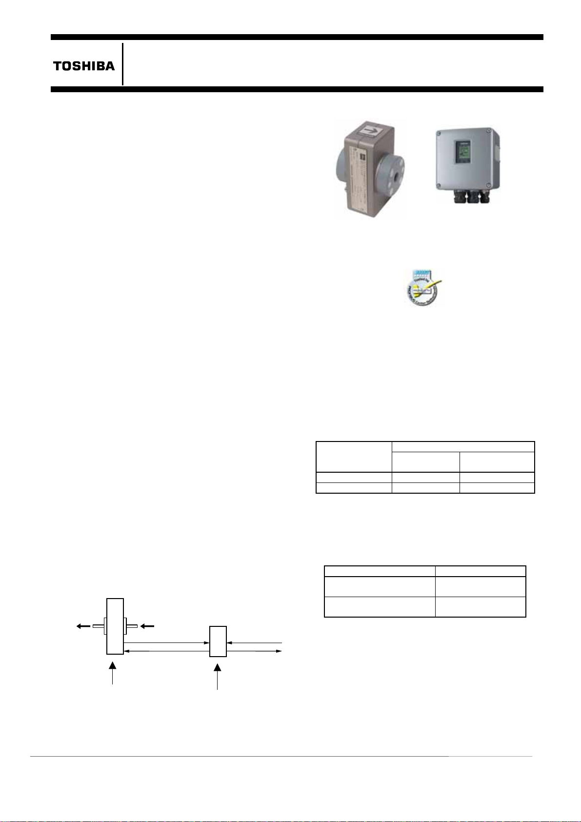
Electromagnetic Flowmeter
containing substances such as chemicals.
The wetted materials for the LF470 are corrosion
resistant ceramic and platinum electrods and are
applicable to almost any kind of fluids. The LF470 is a
lightweight palm-sized detector.Combined with
multi-functional converter LF612 (separate type) and
LF232*
1
(separate type) equipped with its patented
Noise-Sentry original noise-suppression circuit and
advanced algorithms. The LF470 is highly resistant to
noise and provides a stable output even for fluids
containing slurries. IR (Infrared) switches enable
Specifications
Overall Specifications
parameter setting of the converter without removing the
cover. Flow direction can be set in either way, and its
unique 128 x 128 dot matrix LCD display allows the
LCD to be rotated electronically to be rotated to 90, 180
and 270 degrees without opening the cover
The AF900 hand-held terminal (HART*
can be used to communicate with the flowmeter from a
remote place. PROFIBUS-PA*
3
interface is available
2
communicator)
as an option.
*1: Please refer to the document ”TIC-LF232”.
*2: HART protocol (Highway Addressable Remote
Transducer) is a communication protocol for industrial
sensors recommended by the HCF
Foundation).
*3: PROFIBUS is the communication protocol for factory
and process automation that the PROFIBUS Organization
recommends. Instead of analog control with a
conventional analog signal (4-20mA), it is the fieldbus
which digitizes all signals. Flowmeters support
PROFIBUS-PA.
Fluid to b
measured
Signal cable
Excitation cable
LF470
Detector
(HART Communication
Power supply
4-20mA dc outpu
and pulse output
LF612 or LF232
Converte
Figure 1. Configuration Diagram
LF470/LF612
1/10",1/6”,1/4" (2.5,4,6mm )
LF470
Figure 2. Electromagnetic Flowmeter
LF470/LF612
Certification number
Z01207
Measurement range in terms of flow velocity:
0–1.0ft/s to 0–32.8ft/s (0–0.3 m/s to 0–10 m/s )
Accuracy: The overall accuracy combined with the
LF612 or LF232 converter is shown in the
following table.
percent of range
50〜100%
0〜50%
Note: The accuracy is measured under standard
operating conditions at Toshiba's calibration facility.
1.0-3.3ft/s
(0.3-1.0m/s )
0.8% of FS
±
0.8% of FS
±
Fluid conductivity: 50µS/cm minimum
Fluid temperature:
Pipe connection material Fluid temperature
Stainless steel and other metals 14 to 248 °F
Polyvinyl chloride
(shock-resistant)
Ambient temperature: 14 to 140 °F (–10 to +60 °C )
Structure: IP67
Power consumption:
・When combined with the LF612 converter:
approximately 12W (20VA)
・When combined with the LF232 converter:
approximately 14W (25VA)
LF612
Accuracy Flow rate as a
(−10
(−10
3.3-32.8ft/s
(1.0-10m/s )
0.8% of rate
±
0.4% of FS
±
120℃)
℃〜+
14 to 140 °F
℃〜+60℃
)
TIC-LF470B
Page 2

TIC-LF470B
2
Model LF470 Detectors
Fluid pressure:
-
15 to 150 psi, or -1.0 to 10 bar
(-0.1 to 1 MPa)
Principal materials:
Measurement tube – Alumina ceramics
Electrodes – Platinum
Pipe connection port:
Standard – 316 stainless steel
Option – Ti (titanium),
Polyvinyl chloride (shock-resistant)+
Ta (Tantalum) for grounding plate,
Polyvinyl chloride (shock-resistant)+
Pt-Ir grounding plate,
Hastelloy C (Equivalent)
Dedicated preformed cables:
・Signal cable
– 2-wire shielded chloroprene
sheathed cable
Overall length: 0.28 inch (7mm)
Length: 0.20 inch (5m)
・Excitation cable – 3-wiren chloroprene sheathed
cable
Overall length: 0.28 inch (7mm)
Length:
0.20 inch (5m)
Coating: phthalic acid resin coating pearl-gray
colored
Weight: approximately 2.2 lb (1.0 kg)
(for each size excluding cables)
Model LF612 converters
Input signals
Analog signal — the voltage signal from detector,
proportional to process flow rate (for LF612
separate type converter).
Digital input DI (opt.)
Signal type: 20 to 30Vdc voltage signal
Input resistance: 2.7kΩ
Number of inputs: one point
DI function — One of the following functions can be
assigned to the optional DI signal.
Range switching — Selects either the higher or lower
range in the unidirectional or bidirectional 2-range
setting.
Totalizer control — Starts and stops the built-in
totalizer.
Fixed-value outputs —Outputs fixed-values for
current and pulse outputs.
Zero adjustment — Executes zero adjustment
(on-stream at zero flow rate).
Output signals
Current output:
4–20mAdc (load resistance 0 to 750Ω)
Note: The current output cannot be used with the
PROFIBUS-PA communication.
Digital outputs — One point (std.) and one more
point is optionally available as follows.
Digital output DO1 (std.):
Output type: Transistor open collector
Number of outputs: One point
Output capacity: 30Vdc, 200mA maximum
Digital output DO2 (opt.):
Output type:
Solid-state relay output (non polarity)
Number of outputs: One point
Output capacity: 150Vdc, 150mA maximum
or 150Vac (peak to peak), 100mA maximum
DO1 and DO2 functions — One of the following
functions can be assigned to DO1 (std.) and/or
DO2 (opt.)
• Pulse output (available only for DO1, DO2)
Pulse rate: 3.6 to 36,000,000 pulses/hr (DO1)
3.6 to 360,000 pulses/hr (DO2)
(Over 3,600,000 pulses/hr, auto-setting)
Pulse width: 0.5 to 500ms (but less than half of
the period for 100% flow rate)
Note: The same and simultaneous pulse is not
available between DO1 and DO2.)
• Multi-range selection outputs (Note 1)
• High, High high, Low, and/or Low low alarm
outputs (Note 2)
• Empty pipe alarm output
• Digital Output Active Status (DO1 and DO2)
(Note 2)
• Preset count output
• Converter failure alarm output
Note 1: Two outputs (DO1 and DO2) are needed for
4-range switching and forward/reverse 2-range
switching.
Note 2:Normal Open (default set) or Normal Close is
selected for alarm outputs when programming.
When power failure occurs, unit will be fault to
Normal Open.
Page 3

TIC-LF470B
Communications output :
• HART (std.) — Digital signal is superimposed on
4–20mAdc current signal as follows:
Conforms to HART protocol
Load resistance: 240 to 750Ω
Load capacitance: 0.25µF maximum
Load inductance: 4mH maximum
• PROFIBUS(opt.)
Protocol: PROFIBUS-PA
Baud rate: 31.25kbps
Bus voltage: 9-30VDC
Consumption electric current of bus: less than 16mA
Manufacture Ident-No.: 093B
Standard Ident-No.: 9740
HEX
HEX
Slave address: 0-126 (Default address is 126)
Profile: Profile Ver.3.01 for Process Control
Devices
Function blocks: AI(Flow)×1 , Totalizer×1
LCD display:
Full dot-matrix 128×128 dot LCD display
(back–light provided)
The data on the LCD inside the converter can rotate
to 90, 180, and 270 degrees by a software, without
rotating the indicator itself. (Combined type only)
Parameter settings — Parameters can be set as
follows:
• IR Switches: Three key switches are provided to
set configuration parameters.
• Digital communication: The AF900 hand-held
terminal or PROFIBUS is needed to set
parameters.
• Zero adjustment: Zero point adjustment can be
started by pressing the switch in the converter.
• Damping: 0.5 to 60 seconds (selectable in one
second increments)
“Field re-verification”
Mag-Prover – Toshiba’s
Zero span calibration tool allows unit to be
re-calibrated and verified using an internal software
program. (For more information contact Toshiba
International Corp.)
Conditions when power fails:
Parameter setting values are stored in non–volatile
memory and the values will be restored when the
power returns to normal condition. The outputs and
display will remain as follows when power fails.
• Current output: 0mAdc
• Digital output: OFF
• LCD display: No display
• PROFIBUS: No communication
Power supply:
One of the following can be selected:
• 100 to 240Vac, 50/60Hz (std.)
(allowable voltage 80 to 264Vac)
• 24Vdc (allowable voltage 18 to 36Vdc)
• 110Vdc (allowable voltage 90 to 130Vdc)
Surge protection:
Arresters are installed in the power supply and a
current signal output circuit to help protect the meter
from lightning and improve personnel safety.
Case: Aluminum alloy (equal to IP 67)
Coating: Acrylic resin-baked coating, pearl–gray
colored
Cable connection port:
Cable glands —
Provided as standard, OD of 11 to 13mm
Material Nylon 66
G (PF) 1/2 male screws
Applicable diameter —
0.433 to 0.512 inch (11 to 13mm)
Note: When PROFIBUS option is specified, cable gland size is φ
6~8mm for signal cable, φ11~13mm for power cable
Vibration resistance:
No resonance to the following levels of vibration:
• 10 to 150Hz with acceleration of 9.8m/s
2
• Vibration of 30Hz with 29.4 m/s2 in 4h in each
direction will not cause any defect to unit.
Note: Avoid using the flowmeter in an environment with
constant vibration.
Dimensions :
See Figure 5
MTBF:
Converter: 220,000 hours (25 years) at 77 °F (25 °C)
based on strict military specification
MIL-HDBK-217F
Detector: 350,000 hours (40 years) at 77 °F (25 °C)
based on strict military specification
MIL-HDBK-217F
3
Page 4

TIC-LF470B
4
(
)
–
φ
(
)
7.87(
00 )
(
)
)
l
N
N
N
Installation
Dimensions
2.20( 56)
4 .02 ( 1 02 )
Excitation ca ble
0.28(φ7)
Figure3. LF470 Dimensions
5.94(151)
2. 91(74 )
74 ±0.3
Sign al cabl e
φ0.28 (φ7)
151
Unit : inch (mm)
φ1.93(φ4 9)
1.46 (37)
.76(70)
*
This length becomes 78mm if the pipe
*
co nn ection p ort t hread is Rc(PT)1 /2
an d Rc (PT )3/4.
1.18( 30)
2-M4
(Mo u nt in g sc re w h o les )
4-φ11
4
0. 43(φ11)
Attachment
取付金具
LCD display
LCD 表示器
15 1
151
5.94
IR S wi tc h
赤外線スイッチ
Cable ground
ote: 1 inch = 25.4mm
178
178
7.01
2
200
1.42(36)
156
6.14
(36) 156
Figure 5. Separate type converter LF612
Unit : inch (mm)
.39(86)
2.95(7 5)
1.18(30)
**
1.18( 30 )
1.57(40)
* *
**
Mounting screws
Detector mounting plate
(4mm thick)
2- φ0.24(φ6 ) hole
4-φ0.20(φ5) hole
ote: 1 inch = 25.4mm
If a mounting plate is needed for the LF470, fix the plate (a)
above to the bottom of the LF470. Depending on which pair of
screw holes used, the mounting angle changes by 90°.
Figure4. LF470 Mounting Board
25
0.98(25) 3.23(82)
82
0.5 1(13
13
Excitation cable ground
励磁ケーブルグランド
Signal cable ground
信号ケーブル
グランド
Blind screw
矢視 A
Unit : inch (mm)
I/O cable ground
電流出力ケーブルグランド
Po wer s upp ly cab le g round
電源ケーブルグランド
封止栓
ote: 1 inch = 25.4mm
Gr ound termin a
接地端子
(M4)
(M4)
取付金具
Page 5

0
Ω
0
Ω
Separate type LF470/LF612 flowmeter
Terminal board
Thick walled steel conduit
IV wire
2
or more
5.5 mm
Grounded with 100Ω or less
ground resistance
Power switch
(External double-pole power switch )
[Instrument panel : ordered separately]
TIC-LF470B
Signal cable
(2-wire shielded hard-rubber
sheathed cable)
(3-wire shielded hard-rubber cable)
Figure 6. Separate type LF470/LF612 flowmeters wiring Diagram
Grounded with 10
ground resistance
Power supply
Current output (4~20mAdc)
or PROFIBUS
Digital output 1
Connected detector
Excitation cable
Power cable
(CVV)
Digital input cable
(CVV-S)
Signal common for DI and DO
Digital output 2
Digital input
(20~30Vdc)
Grounded with 10
ground resistance
Table 1. LF612 Converters Signal Table
Symbol Description Cable
L1 (+)
L2 (-)
GND Ground (for arrester)
FG Frame ground
DI Digital Input (20~30Vdc)
DO1 Digital Output 1
DO2 Digital Output 2
COM Signal Common for DI, DO1, DO2
+
-
X
Y Excitation Output
E
A
B Signal Input
G
Power supply Power cable (CVV)
Current Output (4~20mAdc)
or PROFIBUS
I/O cable (CVV-S)
Excitation cable
Signal cable
or less
or less
5
Page 6

TIC-LF470B
6
Wiring Precautions
(1) Connect the following two cables correctly:
1) signal cable (on the right facing the LF470)
2) excitation cable (on the left facing the LF470)
(2) Do not bend apply excessive force to these cables.
Piping Precautions
(1) Connect the fluid pipe to the pipe connection port
using a joint that matches the Rc (PT) female screw.
Use seal tapes when connecting the pipe to the port
to prevent a fluid leakage. Do not tighten the
connection screw too much.
(2) Design piping so that the detector’s pipe is always
filled with the fluid to be measured, whether the
fluid is flowing or not.
(3) The fluid to be measured must be held still in the
pipe when the LF470 is being adjusted. If the fluid
can not be stopped after the LF470 installation,
install a bypass pipe in parallel with the LF470
flowmeter.
Meter size
To select the meter size:
See Table 3 to 4 and find meter sizes within the
velocity of 0.3 to 32.8 ft/s (0.1 to 10m/s) for a
specified full-scale (measuring range high limit)
flow. Select one that has its full-scale velocity
between 3.0 and 10 ft/s (1 and 3m/s).
Note: Make sure the full-scale flow rate used for the final
planning stage stays within 32.8 ft/s (10m/s) in
terms of flow velocity.
Table 2. Meter size and Flow Velocity (SI unit)
Unit:gal/min
Meter size
(inch)
1/10” 0.02334 0.07115 0.2372 0.7781
1/6” 0.05975 0.1821 0.6071 1.992
1/4” 0.1344 0.4098 1.3660 4.482
0.98 ft/s 3 ft/s 10 ft/s 32.8 ft/s
Table 3. Meter size and Flow Velocity(US unit)
Unit:L/min
Meter size
(mm)
2.5 0.08835 0.2945 0.884 2.945
4 0.2262 0.7540 2.262 7.540
6 0.5088 1.6967 5.090 16.967
0.3m/s 1m/s 3m/s 10m/s
About establishment environment
Do not store or install the flowmeter:
• Where there is direct sunlight.
• Where excessive vibration or mechanical shock
occurs.
• Where high temperature or high humidity conditions
exist.
• Where corrosive atmospheres exist.
• Places that can be submerged under water.
• Where there is a sloped floor. To put the flowmeter
temporarily on the floor, place it carefully with
something, such as a block, to support it so that the
flowmeter will not topple over.
In areas like the following, there may be the case that
infrared switches do not function correctly. (If these are
unavoidable, use an appropriate cover.)
(1) Where unit (operation panel) is exposed to direct
sunlight, reflection of light onto window pane and
diffused light reflection.
(2) Where smoke and steam may occur.
(3) Where exposed to direct snow, ice or mud.
Ordering Information
1. When ordering the LF470 flowmeters, refer to
Tables 4 to 5 (Specification Code).
An entry must be made for each of the columns in
each of these tables.
2. Fluid characteristics:
(1) Type of fluid to be measured and its characteristics
(2) Fluid temperature
(3) Fluid pressure
(4) Electrical conductivity of the fluid
3. Measuring range
4. I/O function setting
5. Ordering scope:
Flow calibration data: (required or not)
6. Other items
Specifications other than standard items
Consult a Toshiba representative before ordering when
choosing materials of the wetted parts such as lining,
electrodes, and grounding rings.
.
Page 7

TIC-LF470B
Table 4. Specification Code ( LF470 Detector )
Model Specification Code
1 2 3 4 5 6 7 8 9 10 11 12 13 14
L F 4 7 0 LF470 Flowmeter
Meter size
2 1/10" (2.5 mm )
4 1/6" (4 mm )
6 1/4" (6 mm )
Converter ( Separate type ) combined
D LF612
E LF232 (Note 1)
Pipe connection port (adapter)
A Rc (PT) 1/4 female screw (standard)
B Rc (PT) 1/8 female screw
C Rc (PT) 3/4 female screw
D
Pipe connection material
A 316 stainless steel (standard)
D Ti (titanium)
E Polyvinyl chloride (shock-resistance)+
F Polyvinyl chloride (shock-resistance)+
H Hastelloy C (Equivalent)
Packing used between main body and pipe
C Acid-resistant ceramic
D Alkali-resistant ceramic
G Ammonia-resistance
Mounting
A Not provided
B Provided, 304 stainless steel
Flow and calibration velocity range
A 1.0 to 32.8 ft/s (standard range calibration)
B 1.0 to 32.8 ft/s (specified range calibration)
Cable length
A 5m (cable dia.7mm)
1 10m (cable dia.7mm)
2 15m (cable dia.7mm)
3 20m (cable dia.7mm)
4 25m (cable dia.7mm)
5 30m (cable dia.7mm)
B 5m or more
Coating
A Phthalic acid resin coating pearl-gray colored (standard)
Z Other
Rc (PT) 1/2 female screw
E
F
G
NPT1/4 female screw
NPT3/8 female screw
NPT1/8 female screw
Ta (Tantalum) for grounding plate
Pt-Ir for grounding plate
connection adapter
(extension dia. 12mm+Scotch cast connection)
Description
Note 1: Please refer to document number “TIC-LF232” about converter LF232.
7
Page 8

TIC-LF470B
/
Model Specification Code
1 2 3 4 5 6 7 8 9 10 11 12 13 14
L F 6 1 Electromagnetic flowmeter converter
2 Separate (Remote) type
B Shape
E Instruction manual
Code explanation: : Standard : Option
Table 5. Specification Code for converters
A
Converter mounting fitting
A
C
E
1
2
1
2
1
2
3
Contents
Purpose
Standard
Separate type with case
None
Panel, Accessory for wall mounting (BNP material: SUS304)
Accessory for pipe installation (BNP material: SUS304)
Digital input/output
Digital output points 1 (DO1)
Digital output points 2 (DO1+DO2) +Digital input point 1 (DI)
Current output and Communication function
Current output + HART communication
PROFIBUS communication (Current output is not usable)
Power supply
100Vac-240Vac, 50/60Hz
24Vdc
110Vdc
English
LF612
type
ISO9001 and ISO14001 are certified.
Misuse of this product can result in damage to property or human injury.
Read related manuals carefully before using this product.
TIC-LF470B
Specifications are subject to change without notice.
Printed in Japan 2008-5 (TDOC)
© TOSHIBA Corporation 2008
All Rights Reserved.
http://www.toshiba.com/ind
 Loading...