

Page 1

TOSHIBA
6F8A07.70
ELECTROMAGNETIC FLOWMETER
MODEL LF434/LF404
INSTRUCTION MANUAL
-TOSHIBA COHRORATION
Page 2

TOSHIBA
NOTICE
Tills M^iuiol is desigiisci to assist in installing, operating, and inainLaining the
LF434/lT4()4dt:clromagneric flowmeter- For safety reasons, and to obtain the opti
mum pcrtormancc from Ihe flowmeter, read this Manual thoroughly before w'orking
with the product. Keep the Manual within easy reach for reference whenever needed.
The flowmeter to which this Manual refers is NOT designed for applications in which
the functioning of this product is critical to human safety, such as:
♦ Main control systems of nuclear power plants; safety systems in nuclear facilities
• Control systems of medical equipment, including life support machines.
6F8.A077 0
or other critical control lines directly affecting human safely.
NOTES
1. The reproduction of Ihe contents of this Manual in any form» w'hether wholly or in part» is
not permitted without explicit prior consent and approval,
2. The information contained in this Manual is subject to change or review' without prior
notice.
3. Re sure to follow all ,safeiy, operating and handling precautions described in this Manual
and the regulations in force in the country in which this product is to be used,
HART is a registered trademark of the llAR'l’ C’omniumcatioii Foundation.
Teflon is a registered trademark of the DuPont Company.
I’hird Edition
October.
© Copyright 1999» 2000 by Toshiba Corporation, All rights rc,scrved.
2im
Page 3

TOSHIBA
SAFETY PRECAUTIONS
Siifeiy signs and InhcJs affixed to Ihc product iUid/ur dcscribetl in Ihis manual give imporLaiU
inibrmation for using the produci saldy. I’hcy help prevent damage lo property and obviate
hazards for persons using the product.
Make yourself familiar with signal words and symbols used for safety signs and lab els/Then
read the safely precautions that follow to prevent an accident involving personal injuiy>
death or damage to [>ropcrty,
IvxplaDation of signal words
'flic signal word or words are used to designate a degree or level of hazard seriousness,
I’he sigrial words used for the product described in this manual arc WARNING and
CAUTION,
A WARNING
6F8A0770
Indicates a potentially ha/ardous situation
which, if not avoided, could result in death or
‘icrious injury,
Safety symbols
Indicates n potentially iiazardous silualion
A CAUTION
The following symbols arc used in safely signs and labels affixed to a product and/or in the
manual for giving safely inslniciioiiM.
Indicates an action that is prohibilud. Simply [DON’T do this action,
The prohibited action is indicated by a picture or text inside or next to
0
•
A
the circk
Indicates an action that is mandatory, DO this action.
The mandatory action is indicated by a picture or text inside or next lo
the circle.
Indicarcs a poieniial hazard, The potentially hazardous situation is
indicated by a picture or text inside or next to (he triangle.
which, if not avoided, may result in minor to
moderate injuries or in properly damage.
- 2 -
Page 4

TOSHIBA
SAFETY PRECAUTIONS
Safety Precautions for Installation and Wiring
Zh WARNING
Do not disconnect while circuit \s iive onlcss locution is known to be nonhazardous.
6F8A0770,
0
DONT
I Do not modify or disassemble the enclosure.
DONT
Do not use parts of other products.
0
DONT
Do not live circuits While assembly of all components is not over.
0
DONT
Install per the National Electrical Code for the UгS (NEC, ANSI/NFPA 70)
and the Canadian Electrical code for Canada (CEC, CAN/C5A-C22.1).
O
DO
Live part of electric circuit ot a high temperature department can cause
explosion.
Strength degradEilion and defects of enclosure can cause explosion,
Protective pcrformiincc degradation for hazardous location can cause
explosion.
Protective performance degradation for hazardous location can cause
explosion.
Unsuitable conduit connections for hazardous location can cause ex
plosion.
A CAUTION
■ Turn off maius power before working
on pipes«
A Working on pipes vvhiJc
power is applied can cause
QQ electric shock.
■ Install a switch and fuse to isolate the
LF434/LF404 from mains power.
A A Power supply from mains
power can cause electric
DO t>reakdow n.
■ Use an appropriate device to carry
and install the LF434/LF404.
If this product falls to the
ground^ injury, or malfunction
of or damage to the product,
can be caused.
■ Do not modify or disassemble the
LF434/LF404 unnecessarily.
Modifying or disassembling
( jy [his product can cause electric
nOisf’T
- 3 “
shock, malfunction of or
’ damage to this product. |
Page 5

TOSHIBA
SAFETY PRECAUTIONS (contiaued)
Safety Precautions for Maintenance and Inspection
âs CAUTION
■ Turn off mains power before
conducting wiring work.
Wiring while power is applied can cause electric shock,
DO
■ Do not conduct wiring work with bare
hands.
Rcma i n i n g cJ cetr ic charge
( even if pov-'cr is turned off
^ can still cause electric shock.
DONT
■ Do not work on piping and wiring with
wet hands.
Wet hands may result in
f electric shock,
DON'T
■ Do not touch the flowmeter main
body when high temperature fluid is
being measured.
The fluid raises the main
i body temperature and can
^ cause bums when touched.
DON’T
■ Do not conduct wiring work with wet
hands.
1^0 Wet hands may result in
elccrric shock.
DONT
■ Do not use a fuse other than the one
specified.
Using a fuse other than the
j one specified can cause
j/ system failure, damage or
malfunction,
DONT
■ Ground (he LF434/LF404 indepen
dently from power equipment.
PQ shock or malfunction.
■ Use compression terminal lugs with
insulation sleeve for the terminal
block and GND terminal.
/ i \ (A black border and symbol on
■ Do not conduct wiring work when
power is applied.
I can cause electric shock,
DONT
* near the terminal board for
Use a rated fuse as follows:
Fuse rating:
^ lA/^.'inV for lilt) to 240Vac or 1 liiVdc
* 2A/2.^0V for 24 Vdc
Dimensions:
Diameter
Melting time characteristic:
6F8A07 7 0:
Operating this product without
grounding can cause electric
1.0QSC connections can cause
electric shock, fire from
excessive current or system
malfunction.
The label shown left is placed
near the terminal board for
power input.
yellow triangle)
Be alert to electric shock.
Wiring while power is applied
1 be label shown left is placed
power inp ut.
\ (A black border and symbol on
yellow triangle)
Be alert to electric shock.
5.2
mm x 20 mm
Normal blow j
Disclaimer
Toshiba does not accept liability for jny damage or loss, material or personal, caused as a
direct or indirect result of the operation of this product jii connection with, or duo to, llie
occurrence of any event of force majenre (including fire or earthquake) or the misuse of
this product, whether inicnclonal or accidentaL
- 4 -
Page 6

TOSHIBA
Handling Precautions
■ Jo obtain the oplimum performance from the LF434/LF404 flowmeter for years of
coniinLous operation, observe the following precautions.
(1) Do not store or instafi the flowmeter in:
(2) Execute wiring securely and correctly.
.6.F8A0 770
• places w here there is direct sunlight. If this is unavoidable, use ait appropriate
sunshade.
• places where excessive vibration or mechanical shock occurs,
• places where high temperature or high humidity conditions obtain.
• places where corrosive atmospheres obtain.
• places submerged under water,
To put the flowmeter temporarily on the floor, place it carefully wnth something to
support it so that the flowmeter will not topple over.
Ground the flowmeter with 100 ohm or less ground resistance. Avoid a common
ground used with other equipment where earth current may How. An independent
ground is preferable
(3) Seal the cable thoroughly at the cable gland so that the cable is kept airtiglit. 1 he
apparatus should not be provided with the cable gland. Please prepare yourself for
the cable glands w'hicb could be used in Division 2 hazardous locations.
(4) Make sure the fluid to be measured will not freeze in the detector pipe. This can
cause damage to the detector pipe.
(5) Select apprupriate welted materials suited for the process fluid to he measured.
Otherwise, fluid leakage due to corrosion can be caused.
(6) The converter housing covers are tightened securely at the time of shipment. Do
not remove these awers or glands unless it is necessary to wire new cables or re
place old ones. Otherwise, gradual deterioration of circuit isolation or damage to
this product can be caused. Tighten the covers securely again if they have been re[iioved.
L
“
5
-
Page 7

TOSHIBA
Handling Precautions (continued)
j (7) Observe the following preenulions when you open the converter housing cover:
• Do not open the cover in .he open air unprotected ngninst rain or wind, J his
cun cause electric shock or cause damage to the ilowmetcr elccironics.
* Do not open the cover under high ambient temperature or high humidity
conditions or in corrosive atmospheres^ This can cause deterioration of
system accuracy or cause damage to the flowmeter dec ironies,
(B) This product may cause interference to radio and television sets If they are
used near the installation site. Use metal conduits etc, for cables to prevent
thi.s interference.
(9) Radio Iransmiilers such as tran.sceivers or cellular phones may cause interference
to the ñowmcter if they are used near the installation site. Observe the following
precautions when using them:
• Do not use a radio transmitter while the cover of flowmeter converter is open.
• Do not use a tran.scciver whose output power is more than 5 W.
• Move the antenna of a ratio transmitter at least 50 cm away from the flowmeter
and signal cables when using it.
• Do not use a radio traiismitler near the ñowmeler while it is operating online.
The transmitter's output impulse noise may interfere with the flowmeter.
• Do not install a radio transmitter antenna near the flow'meier converter and
signal cables.
,6F8A0770
(10) For reasons of flowmeter failure, inappropriate parameters, unsuitable cable con
nections or pCHjr installation conditions, the flowmeter may not operate properly.
To prevent any of these problems causing a system failure, it is recommended that
you have preventive measures designed and iitstallcd on the flowmeter signal re
ceiving side.
- 6 “
Page 8

TOSHIBA
Table of Contents
678A0770
SAFETY PRECAETfONS
Handimg Precautions ........................................................
1, Product Inspection and Storage ...............................
1.1 Product Inspection ...................................................
1.2 Storage .....................................................................
2, Overvie>v ....................................................................
3, Names of Parts
...........................................................
4, Installation ..................................................................
4.1 Location ...................................................................
4.2 Mounting Procedure.................................................
4.3 Piping Connections
.................................................
5, Wiring .........................................................................
5A
Cables
5.2 External Device Conncc.ions and Grounding
5.3 Digital I/O Connections
5.4 Wiring Procedure ......................... ‘ '
.....................................................................
......................
6, Operation ................................................
6.1 Preparatory Check
6.2 Zero Adjustment
7, LCD Display and Controls
7.1 Outline
7.2 Display Formal
7.3 Basic Operations .................................................
7.4 Configuralion Items Selection Table ' ■
7.5 Password Input
................................................
8» Configuration Parameter Setting
8.1 Configuration Items ............................................
8.2 Checking or Changing Parameters
..............................
.................................
...................
...................................................
...................................................
..........................
.....................
9. Calibration .............................................................
9.1 Calibration Items
9.2 Calibration Using Converter Signal Source
................................................
■ 2
-■5
■
9
10
11
14
15
' 16
' 20
‘ 25
■ 27
■ 27
29
’ 30
■ 32
' 32
33
‘ 34
34
■ 36
■ 38
‘ 44
■ 45
^ 46
■ 46
■ 46
103
103
104
9
g
-
7
-
Page 9
TOSHIBA
6F8A0 7 7 0.
10, Digital I/O Functions
10.1 Digilai I'O Spccjficaiians '
L0,2 Totalizer and Pulse Output
10.3 Multi-range Functions ■ ■ ’
10.4 High and Lou Limit Alarms
10.5 Empty Pipe Alarm
10.6 Preset Point Output
10.7 Remote Zero Adjustment
10.8 Remote Selection of Fixed Value Output
10.9 Converter Failure Alarms ................................
tl. Communications Function
11.1 Communications with the AFIOO Terminal
11.2 Communications Procedure
1 L3 Cautionary Notes on Communications ‘ '
12, Self-Diagnostics and Alarms
12J Self-Diagnostics
12.2 Output Status for Errors and Alarms
13, Maintenance and Troubleshooting
13.1 Maintenance
...................
.....................
.................................
...................................
..............
........................................................
.........................
................................
...........
.............
...................
13.2 Troubleshooting
14, Principle of Operation
...................
....................
15, Specifications ..............................
15.1 Flowmeter Specifications
15.2 Type Specification Code
16, Outline Dimensions .
.................
Appendi\ 1. Electromagnetic Compatibility and Low Voltage Safety ’
Electromagnetic Compatibility
Low Voltage Safety ^ ^ ■ ■ ■ ■ ►
- 8 -
Page 10

TOSHIBA
1, Product Inspection and Storage
i;pon arrival of The product piickfige» open [lie package and check the items contained inside,
If you do not intend to install the product soon after opening llie package, store the product
and other related items in a place such as described in 1.2 below,
IJ Product Inspection
The LE^34/LF404 electromagnetic flowmeter is shipped in a cardboard cnniaincr filled with
shock-ahsorbing materials. Open the package carefully and check as follows:
■ Make sure the following items are included in the package.
(1) Model LF434/LF404 Electromagnetic Flowmeter,.,.,, i
(2) Instruction Miitiual ..............................................................
■ Inspect the flowmeter for indications of damage that may have occurred during shipment.
■ Make sure the type and spedficalions of the flowiiieter arc in accordance with the
ordered specifications,
If you cannot find the items listed above or any problem e?(ists, contact your nearest
I’oshiba representative,
6F8A0770
j
1,2 Storage
To store the LF434/LF404 flowmeter after opening the package, select a
storing place as follows and keep it under the conditions described below;
(1) Avoid places where there is direct sunlight, rain or wind.
(2) Store the product in a wcll-veniilated place. Avoid places of extremely high
humidity or extremely high or low temperature. The following cnvlroiitucnt is
recommended;
« Humidity range: 10 to 9i)% RH [no candensation)
• Storage temperature: -15 to +65* C
(2) Avoid places where vihralions or mechanical shock occur.
(4) Do not leave the converter housing cover open . Open the cover only w-hen
you actually start wiring cables. Leaving the cover open catt cause gradual
dctcrioraiion of circuit isolation,
(3) To pm the flowmeter temporarily on the floor, place it carefully with something
to support it so that the flowmeter will not topple over
- 9 -
Page 11

TOSHIBA
2. Overview
6F8A0770
The LF434/1P4U4 elecLromagnetic flowmeter can be use in the following hai:afdoLis (clas
sified) loc;iLions.
(1) FM Approval
Gass I j Division 2, Groups A, C, C and D,
Class II, Division 2, Groups P and G
Class in
(2) eSA Ccrtifieation
Class I , Division 2, Groups A. B, C and D,
Class n , Division 2, Groups R, i- and G
GassU
rhe device measures the volumetric flow rates of electrically conductive materials on
the basis of Faraday's Law of electromagnetic induction.
The device consists of two units: Ue detector, through which the fluid to be measured
flows, and Ihe converter, which receives the elcciromotivc force signals from tiie
detector, then converts the signals into the 4—20 mAdc signal.
Features
Model 1F434/LF404 flowmeter has the following features:
(1) Fluid flow is not obstructed and pressure loss is negligible.
(2) Toshiba’s original noise-suppression circuit with signal processing
Ccipcibililics ensures a stable outpul.
(3) lias no moving parts and How indication is quick with high accuracy even under low
flowrate measurement conditions,
(4) No obstacles in the flow stream ami nowhere remains the fluid along the detector
pipe. Thus deterioration or corrosion of fluid does not occur,
(5) High accuracy, ±0.5% of rale is possible for 0,3-10 rrv’s velocity range. (). I to 0.3
m/s range is available optionally.
(6) 'I'he flowmeter has various How measurement outpul and control functions as
standard specifications and the optional IXD display for convenient parameter
settings.
' These funciions can he selected with control keys on the panel.
(8) Intelligent functions
* The widely used HART [protocol communications system is used as a standard
feature. HART (Highway Addressable Remote Transducer) is a commtmications
protocol for industrial sensors recommended bvHCF (HART Communication
Foundalion).
(9) An casy-to-rcad LCD display (2-iine x 16-character display) (optional)
* The backlit LCD display can be read even under poor lighting conditions.
- 1 0 -
Page 12
TOSHIBA
3. Names of Parts
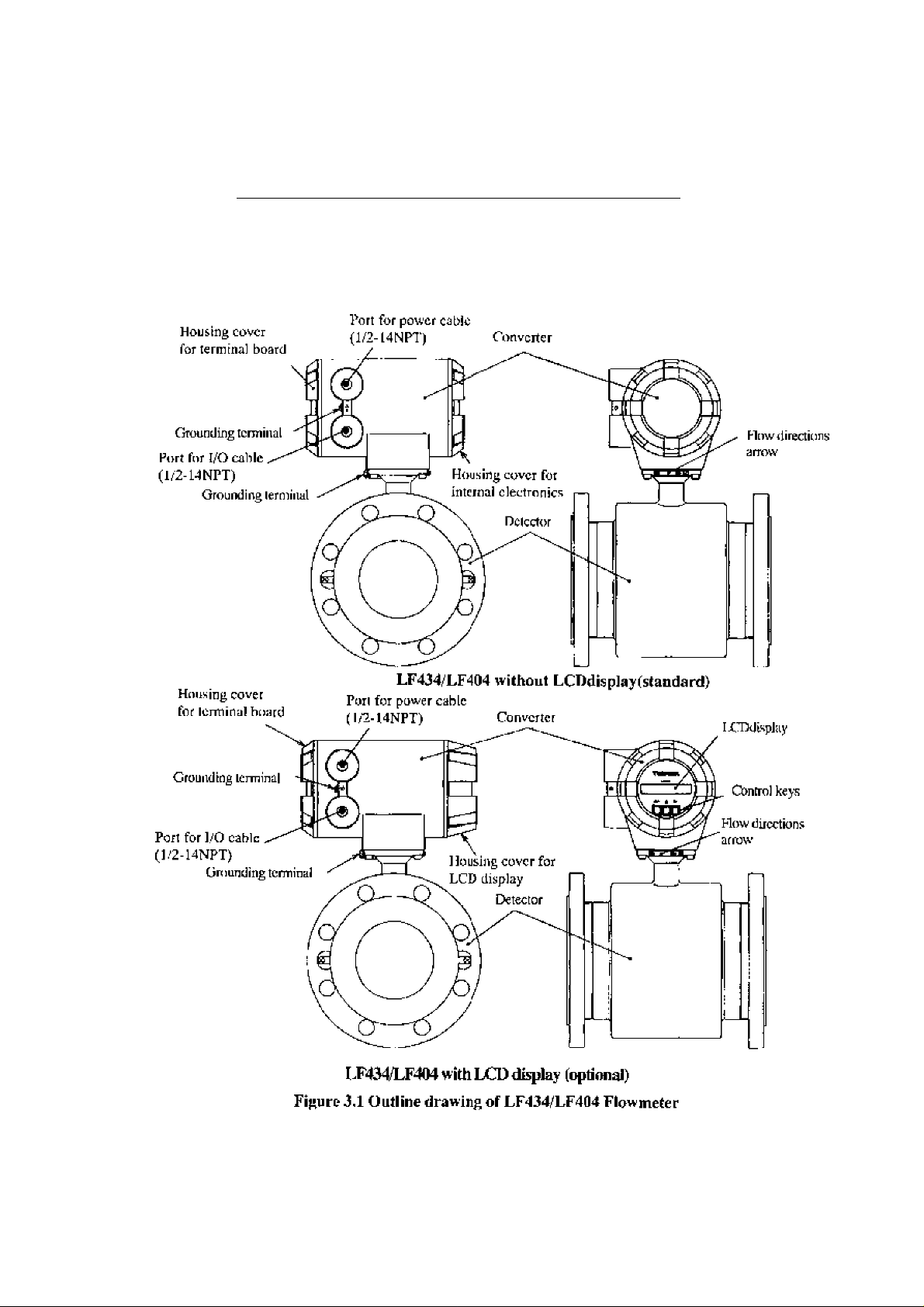
Tht: oulliEie drawing of ihe LF434/LF404 ilowm&ter is shown in Figure 3,1 and the in-
______________
IMPORTANT
The apparatus should not be provided with the cab'c glands.
Please prepare yourself for the cable glands which could be used in Division2 hazardous locations.
tcrnal views of the LF4[14 converter are shown in 1 ifiiires 3,2 and 3.3,
Outline Drawing
_______________
6F8A0770
- M -
Page 13
TOSHIBA
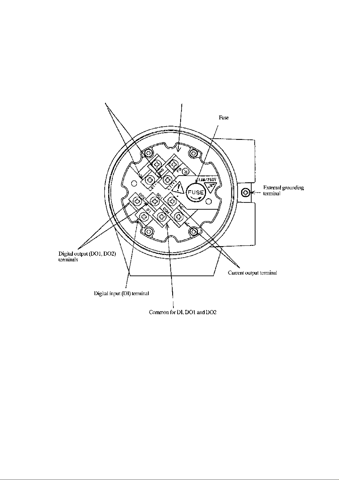
Terminal Board ol'LF404 Converter
.6F8A07 7 0
Power supply lerminal:^
interna] gi\>uniJing terminal
Figure 3.2 Terminal Board of LF404 Converter
- 1 2 -
Page 14
TOSHIBA
Control switch or keys of LF404 Converter
6F8A0770
LF4M v^ithout LCD Display
LF4(W wilh TXD Display
LCD display
Control keys
Figure 33 Control switch or keys of LF404 Converter
-
13
-
Page 15

TOSHIBA
4. Installation
Safety Precautions for Installation
Do not live circuits under environmeiu of explosive aimosphcrcs.
6F8A0770
A WARNING
0
DON’T
Do not use parts of other products.
0
DON’T
l>o not Jive circuits While assembly of all components is not over.
0
DON’T
Install per the National r.lectricnl Code for the US (NEC, AN\SJ/NFPA 70)
and the Canadian Electrical code for Canada (CEC» CAN/CSA-C22»!).
O
DO
Live part of electric circuit or a high tompcralure department can
cause explosion.
Protective performance degradation for hazardous locatinn can
cause explosion.
Protective performAnce degradation for haijardous location can
cause explosion.
Unsuitable conduit connections for hazardous location can cause
explosion.
A CAUTION
■ Install a switch and fuse to isolate
the LF434/LF404 from main power.
Power supply from main
power can cause electric
shock or ci rcu It
DO breakdown.
■ Use an appropriate device to carry and
install the LF434/LF404.
If his product falls to the
ground, injury, or
malfunction of or damage to
PQ the product, can he caused.
■ Do not modify or disassemble the
LF434/LF404 unnecessarily.
Modifying or
disassembling this product
1 jjw can cause electric shock,
malfunction or damage to
DON’T this product.
■ Do not work on piping and wiring
with wet hands.
Wet hands may result in
V Jy electric shock
DON’T
- 14 -
■ Ground the LF434/LF4M
independently from power equipment.
Operaliiig this product without
grounding can cause electric
0 Q sh ock or m a Ifu notion.
1 he label shown left is placed
near tile terminal board for
power input.
/ J \ (A black border and .symbol on
yellow triangle)
be alert to dcctric shock.
Page 16

TOSHIBA
4.1 Location
6F8A077.0
['ey
fielect the inslallatioi] site, follow the precautions described below:
■ Avoid places where fluid runs in a pulsating form.
■ Avoid places within the immediaic proximity of equipment producing declricul
inleгf^^rencc (such as motors, transformers, radio irunsmittcrs, electrolytic ceils, or
other equipment causing electromagitclic or electrostatic interference),
■ Avoid places where excessive pipe vibration occurs.
■ Avoid places where there is direct sunlight. !f this is unavoidable, use an appropriate
shade
■ Avoid places where corrosive atmospheres or high humidity conditions obtain,
■ Avoid places of too great an elevation or constricted areas where clearance
for installation or maintenance work is not provided,
■ Design piping so that the dcicetor pipe is always filled with fluid, whether the Quid is
flowing or not,
■ The LF434 detector has no adjustable piping mechanism. Install an adjustable short
pipe w'here needed.
■ Chemical injections should be conducted on the downstream side of the flowmeter.
- 15 -
Page 17
TOSHIBA
4*2 Mounting Procedure
6F8A0770
A CAUTION
■ Use ati approprìate devìce lo carry
and instali thè LF434/LP404*
_ If his product fallii to thè
A & g round, i nj u ry, of
malfuiiction of or damage
DO lo thè produci, can be
caused.
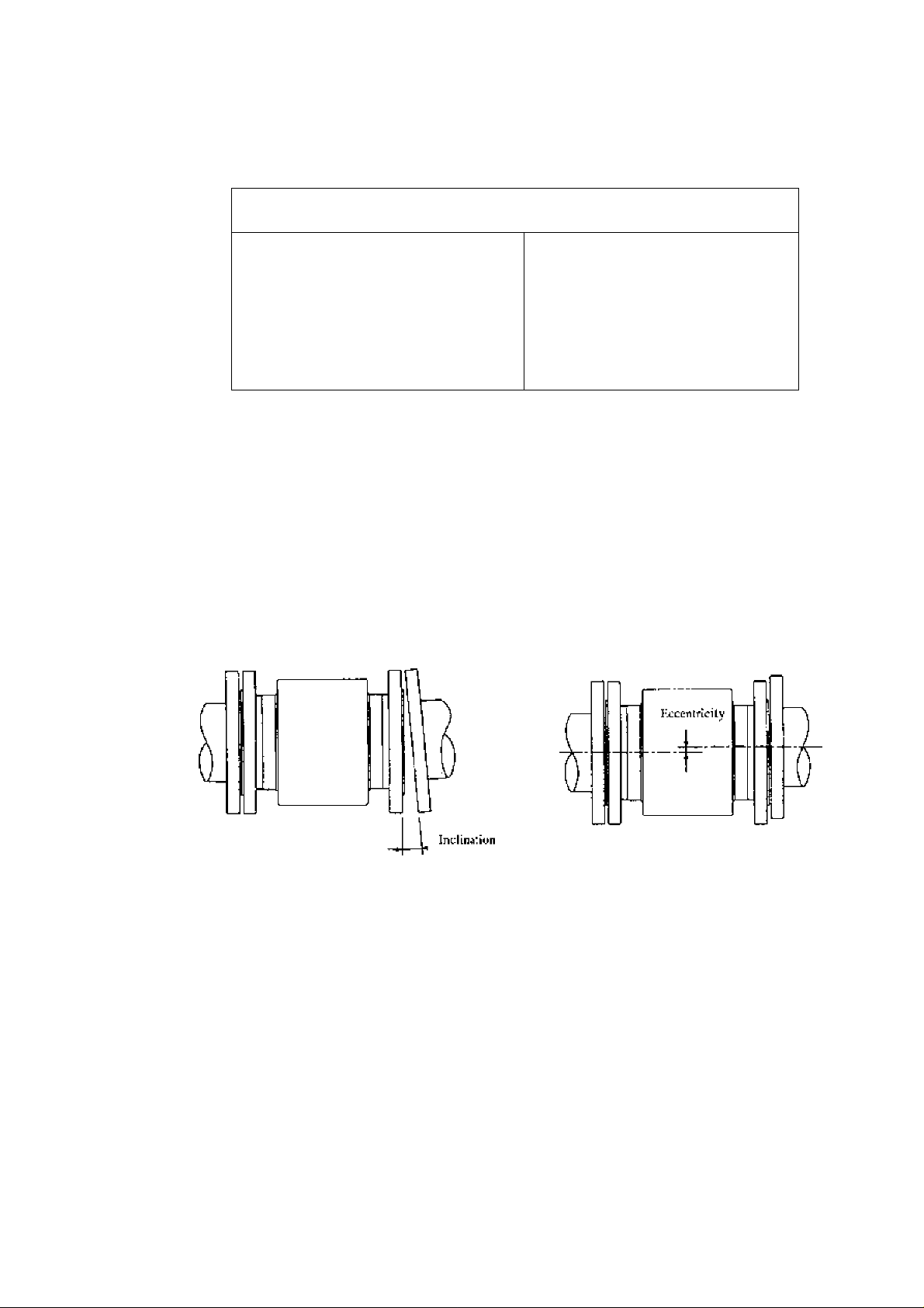
4*2,t Pipe checks
Before installing pipes, cheek for iuiy leanitig or misplacement (or eccentricity) as
iJlusitratcd in Figure 4.1. An attempt to unreasonably connecting pipes that are inclined
may lead to a detector breakdown or fluid leakage. Connecting pipes in an eccentric state
may also cause local wears and tears of linings and grounding rings, as well as
measurement errors.
Before installing pipes* make sure to flash the interior of the pipes to remove deposited
matters.
■ Tum off mains power before
working on pipes.
Working on pipes while
power is applied can
cause
electric shock*
DONT
(a) Pipe leaning (b) Pipe axis misplacement (or eccentricity)
Figure 4.1 Pipe leaning and axis misplacement
- 1 6 -
Page 18
TOSHIBA
4.2.2 Installation Procedure
IMPORTANr
When high-temperuiure fluid is being measured, radiant heal from the detector pipe surface
and adjoining pipes may cause the ambient temperature of the converter to go above 6t)
If the ambient lemperature goes above 60° C, try to lower the temperature by measures such
as wrapping heat-insulating materials over the detector pipe and adjoining pipes.
6F8A0770
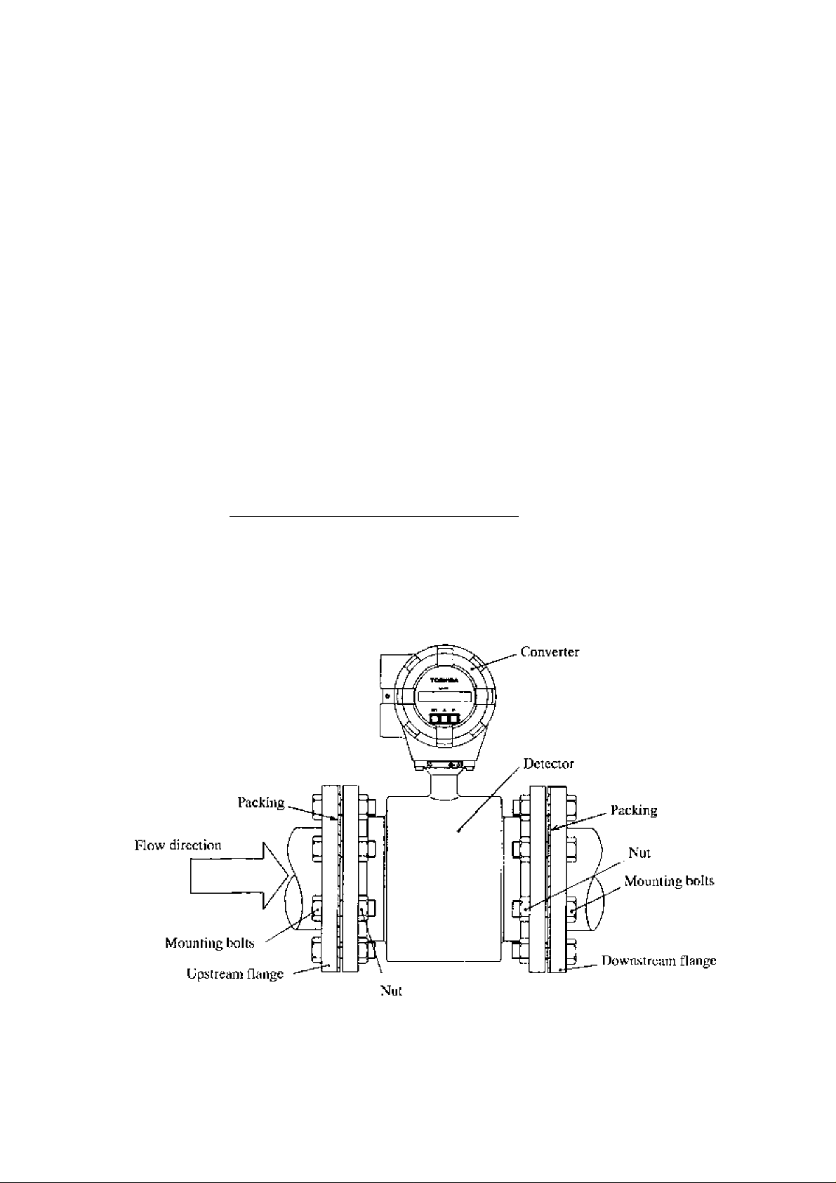
To mouiu thu LF434/J.F404, plai:c il between Itic upstream and downstream pipe flanges
and tighten it with flange holts and nuts. See f igure 4,2 t Tablc4,1 and follow ihe
procedure below:
1. Place one of the flange packing next to the upstream (or downstream) pipe llattge. Altgi^
the holes of the packing with those of the flange so that the holes arc not obstructed.
2, Insert the Lh’434 detector in pipeline in accordance with the flow direction arrow on the
detector.
3, Insert the bolts, one at a time, through the hole in the upstream (or downstream) pipe
flange and packing, and then through the hole of the detector flange. Then thread nuts,
one at a time, on each end of the bolts, finger-tighten. This will help support the detector
on one side.
4, Insert the downstream (or upstream) packing between the detector flange and the down
stream (or upstream) pipe flange. Align the holes of the packing with those of tlie flanges
so that the holes are not obstructed.
5. Inert the bolts, one at a time, through the hole in the downstream (or upstream) pipe
flange and packing, and tJien through the hole of the detector flange. Then thread nuts,
one at a time, on each end of the holts, finger-tighten. This will help support the detector.
6. While centering Ihe detector with ihe longitudinal axis of the pipeline, tighten the bolts
with a wrench diagonally across in even increrr^nis
______________________________
Figure 4,2 LF434/LF4Ü4 flowmeter piping connectinns
- 17 -
Page 19
TOSHIBA
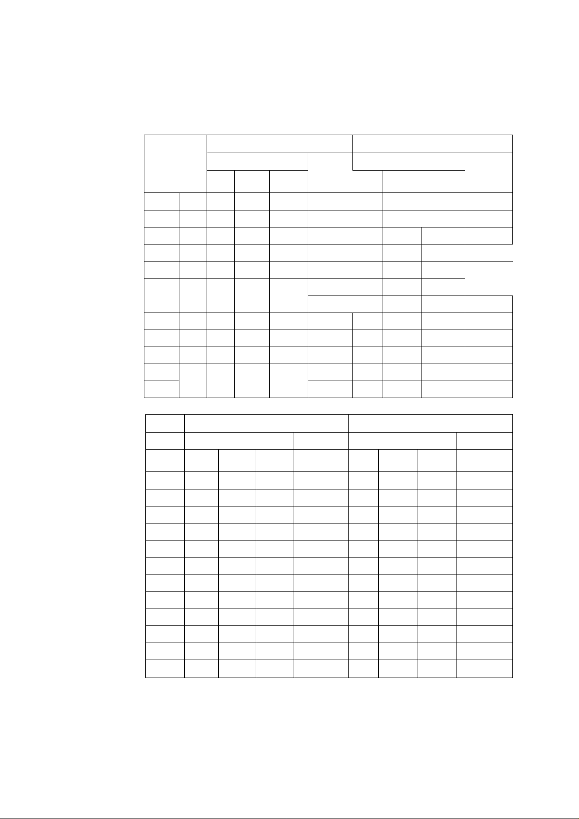
6F8A07 7.0
Table 4.1 Bolt length and Nut tightening torque
ANSI class 150
3”
4”
Clamping
lorque
[N-m]
10 to 13
33 to 41
20 O’o 25
67 10 S3
73(0 91 16 1 i.^S" 5.7” 70 to 88
Clamping
lorque
[NmJ
P.C.S
4
4 3/4”
8
S
16
Jiexagon head boll.s
P.C.S
Mc(cr size
15mm 1;2”
25irim 1" 4 1/2” 2.25”
40mm 1 L'2"
50mm r 4 5/K” 2.75” 26 to 32 8 5/8“ 2.8” 13 to 16
80mm T 4
lOOmm 4"
15Cmm 6" S 3/4” 3.25” 46 to 57 12 3/4“ 4.1“ 30 to 38
20f)mm 8" 8 3/4” 3.5" 6010 75 12 4.7“
25Umm 10’' 12 7/S” 3.^"
500mm 12” 12 7/8”
350mm 14” 12 1” 4.5' 105(0 131 20 1 1.'8“ 5.9” 71 to 89
400mm Ifi” 16 1” 4.5" 98 10 123 20 1 i/4”
Meier
size
P.C.S
Machine Bolts
Diame
P.CS
4
4
8
Hotagon head bolts
ter
1/2” 2” 5 to 7 4 1/2“ 2” 5 hi 7
1/2” 2.5’ 15 to 18
5/8”
5/8” .3”
DIN.'BS 1(1
Diurne-
ler
I,cngih
finml
Length
linch]
ANSI class 300
Machine Bolts
Diame
ter
5.''8” 2.5’' 13 lo 16
3/4“ 3.4”
3/4” 3.7” 24 to 30
1”
Diame
ter
Length
finchl
2,8" 22 to 28
5.4” 57 to 71
6 3”
I31N/BS 16
Lengih
Imml
c:iamping
20tn25
47 to
9810 123
Clamping
torque
[NmJ
ttjrquc
f^‘m|
15mm 4 M12 55 5 to 7 4 M12 .55 5 10 7
25mm 4 M12 60 12 to J8 4 M12
40mm
SOmrri 4 M16 65 26 to 33 4 M16
80mm 8 M16 70 17 to 21 8 M16
100mm 8 M16 75 20 lo25 8 M16 7.5 20 to 25
150mm 8 M20 80 48 to 60 8 M20
200mm 8 M20 85
250mm 12 M20 90 60 to 75 12 M24
300mm 12 M20
35 Omm 16
4{)0inm 16 M24 105 93 to 116 16 M27 115
4 M16
M20
65
95 62 to 78
19 to 23
63 to 79 12 M20 90 42 to 53
65 to 82
4
M16 65 19 to 23
12
16 M24
M24
60 12 to 18
65
70 17 to 21
80 48 to 60
95 72 to 90
lOO 78 to 98
lit) 74 to 93
26 to 33
105 to !31
- 1 8 -
Page 20
TOSHIBA
6F8A0770
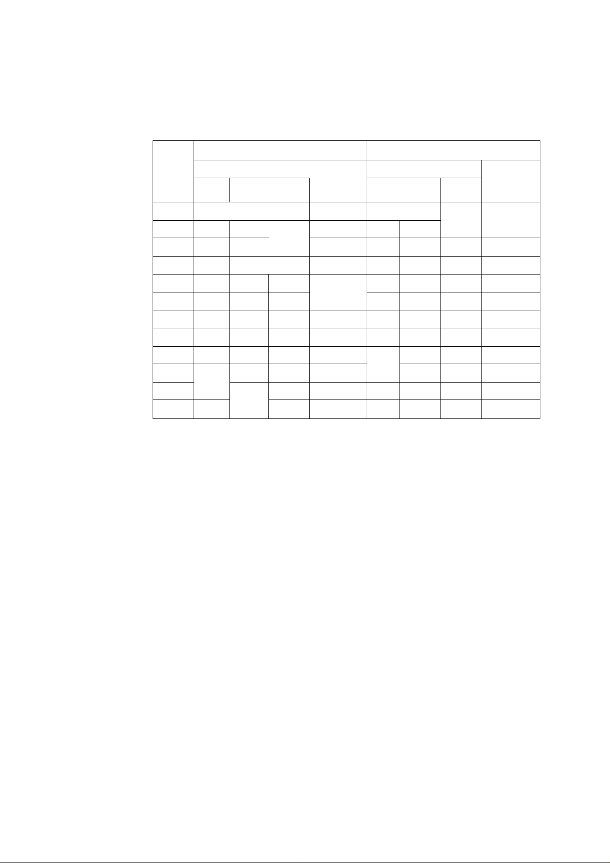
Table 4«1 Bolt length and Nut tightening torque(contjnued)
JIS lOK
M«ler
iSmtn 4 M12 50
Zinmi 4 M16 55 13 to 16
40mm
50mm
K{)inm K M16 65 17 to 21 8
lOOmm S M16 70 20 to 25 8 M20 SO 25 to 32
150mm K M20
2№mm 12 M20 SO
250mm 12 M22 S5
300mm 16
350mm 16
4(J0mm 16 M24 95
[Icxaeon head ht>Us
P.C.S
Diamc-
icr
A
4 M)6 60 26 to 33 8 VI !6 65 13 to 16
M16
M22 85 54 to 67 16
M22 68 to 85 16 M30 125 93 to 116
length
fmml
60 19 to 23
SO 4S to 60 12 M22 9i) 35 to 44
Clamping
torque
[N^m]
5 to 7
42 to 53
66 to H2
93 to ] 16
Hcxagoit head bolts
Djantc-
P.C.S
4
4 M16 60 13 to 16
4
12 M22 95 46 to 58
12
16 M30 140 116 to 145
JiS 20K
Clamping
Length
tcr
M12 55 5 to 7
M16 65
M2U 75 21 to 26
M24 110 72 lo<X)
M24
[mini
110
torque
[NiuJ
] 9 to 23
59 to 74
-
19
-
Page 21
TOSHIBA
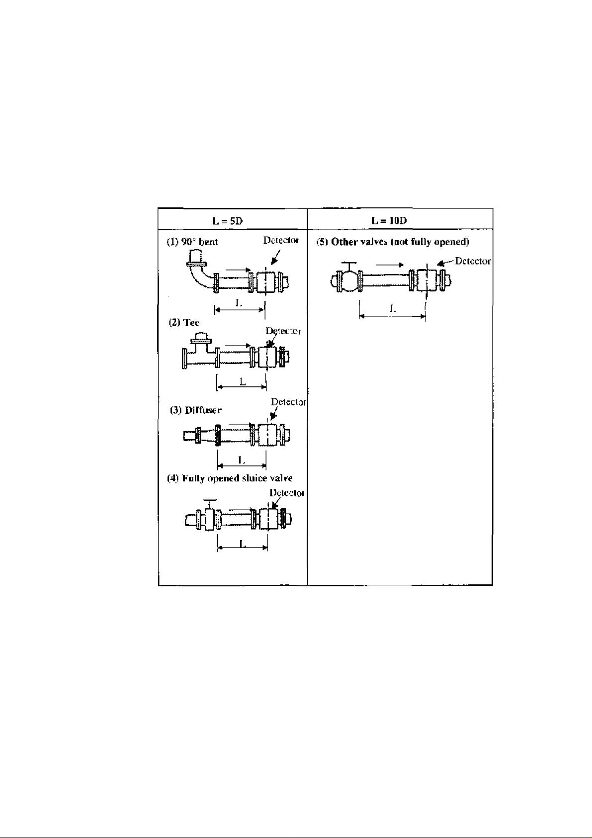
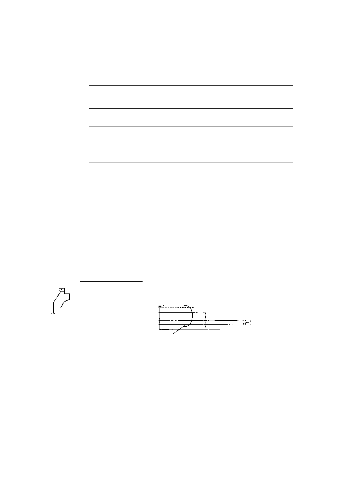
4.3 Piping Connections (t) Required Pipe Length
6F8A0770
[f various; joints are used upstream of Itie deiecior outlet^ llie straight pipe length
shown in TiibJe 4,2 is required.
I'able 4.2 Required straight pipe length on the upslreinn side
L: Required straight pipe length—straight pipe leiiglh pius half length of the detector.
D: Nominal hore size (diameter)
NOTES
1. The length of a reducer, if connected, can he counted as a part of the straight pipe
length.
2.
No straight pipe length is needed on the downstream side, If a butterfly valve is
installed dowiLStream of the detector, do not let the valve plate protrude into the
pipe of the detector
- 20 -
Page 22
TOSHIBA
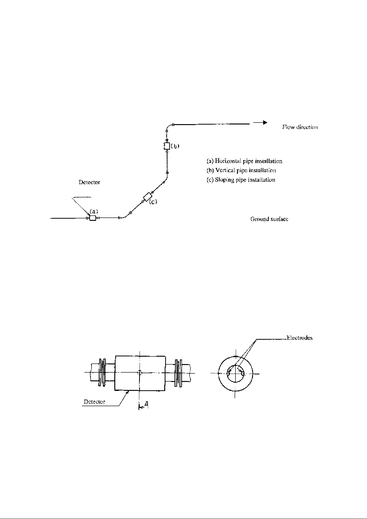
(2) Pipe Orientatir>n
6F8A0770
The delector may
Figure However, except forhorizonlal iiislallatiuii, Quid should flow from lower lo
upper directions- See Figure 4.3.
be
installed in hori/ontal, vertical or sloping pipe runs as shown in
Figure 4.3 Detector Piping Orientation
I hc cJccirodcs should be posilioned horizonlaJly against the ground surface in any piping
installation. See Figure 4.4.
Cmss-scction A - A
Ground surface
Figure 4.4 [nstallatioti position of the detector
- 21 -
Page 23
TOSHIBA
(3) Flow Direction
6F8A0770
Inculi the detector in accord<i!tcowilli (he flow directi on arre won the detector. See Figure 4.ò.
] 11 he act u iit l fi ow mn s opposi te to t h e specif i eci flow d i ree lio it, t ho follo win g d ì spi ay i\lìd
output appears., (For bidirectional multhrange moasurorrient, see 10,3/‘Mulii-rarige
Functions,’*).
' LCD display (optional)i Instantaneous flow rate—indicates negativo values,
Totalized flow—no counts added.
■ Output:Current output— 4.0 mA output; Pulse output^—^No pulses
I'or bidirectional range measurement, the flow in opposite direction results in a positive
output value. Sec 10.3, ‘"Multi-range Functions.*’
Flow direction arrow
Figure 45 Flow direction arrow on the detector
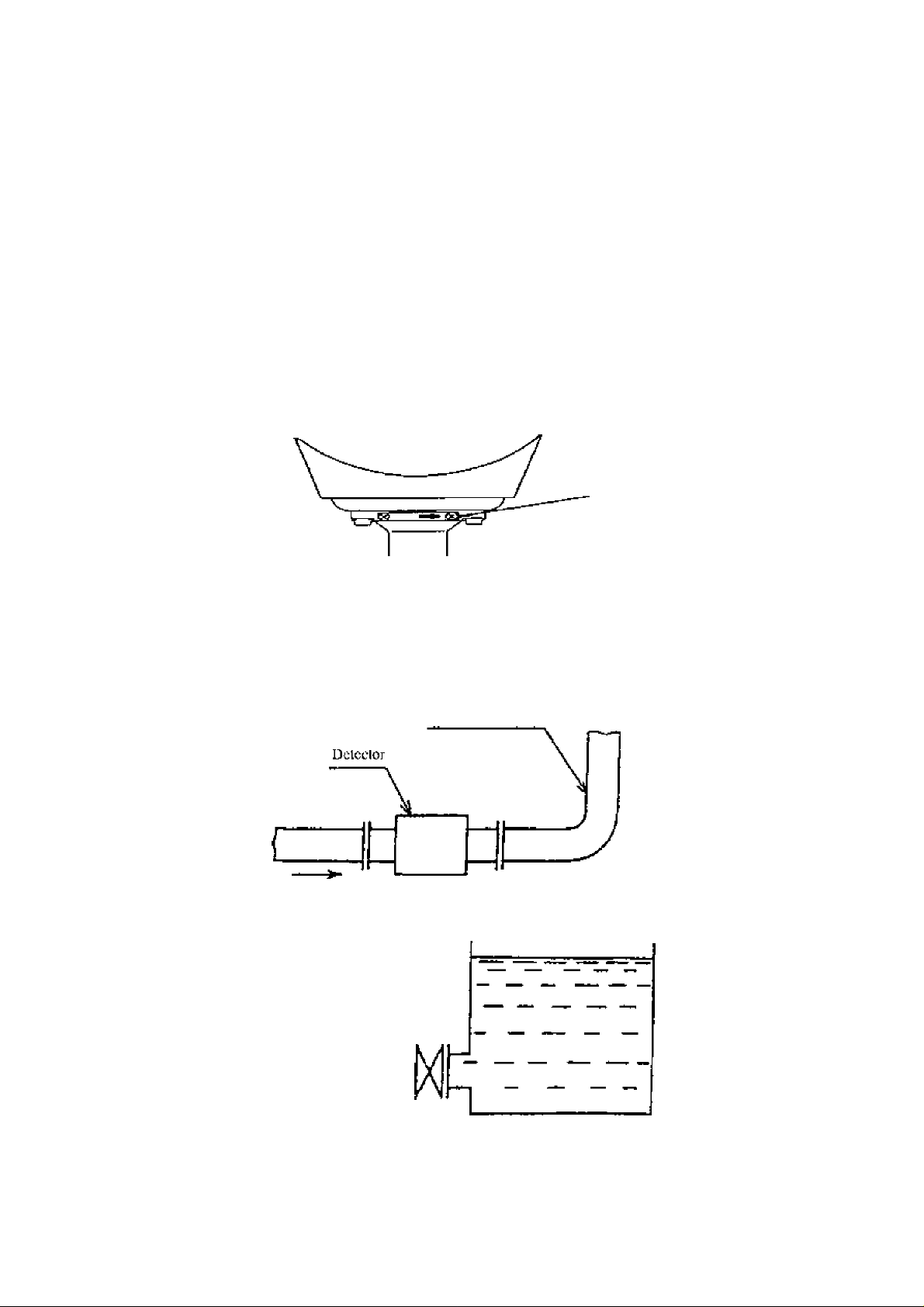
(4) Preventing an Empty Pipe Condition
Design an upright pipe run (Figure 4.6) or sufficicni head pressure (Fig. 4,7) at the
downstream detector outlet if there is a possibiiity of the detector pipe becoming emptied*
Upright pipe run
Figure 4.6 Detector with an upright pipe run at downstream outlet
Detector
CH
Figure 4.7 Detector with suftldecit head pressure at downstream outlet
~ 22 -
Page 24
TOSHIBA
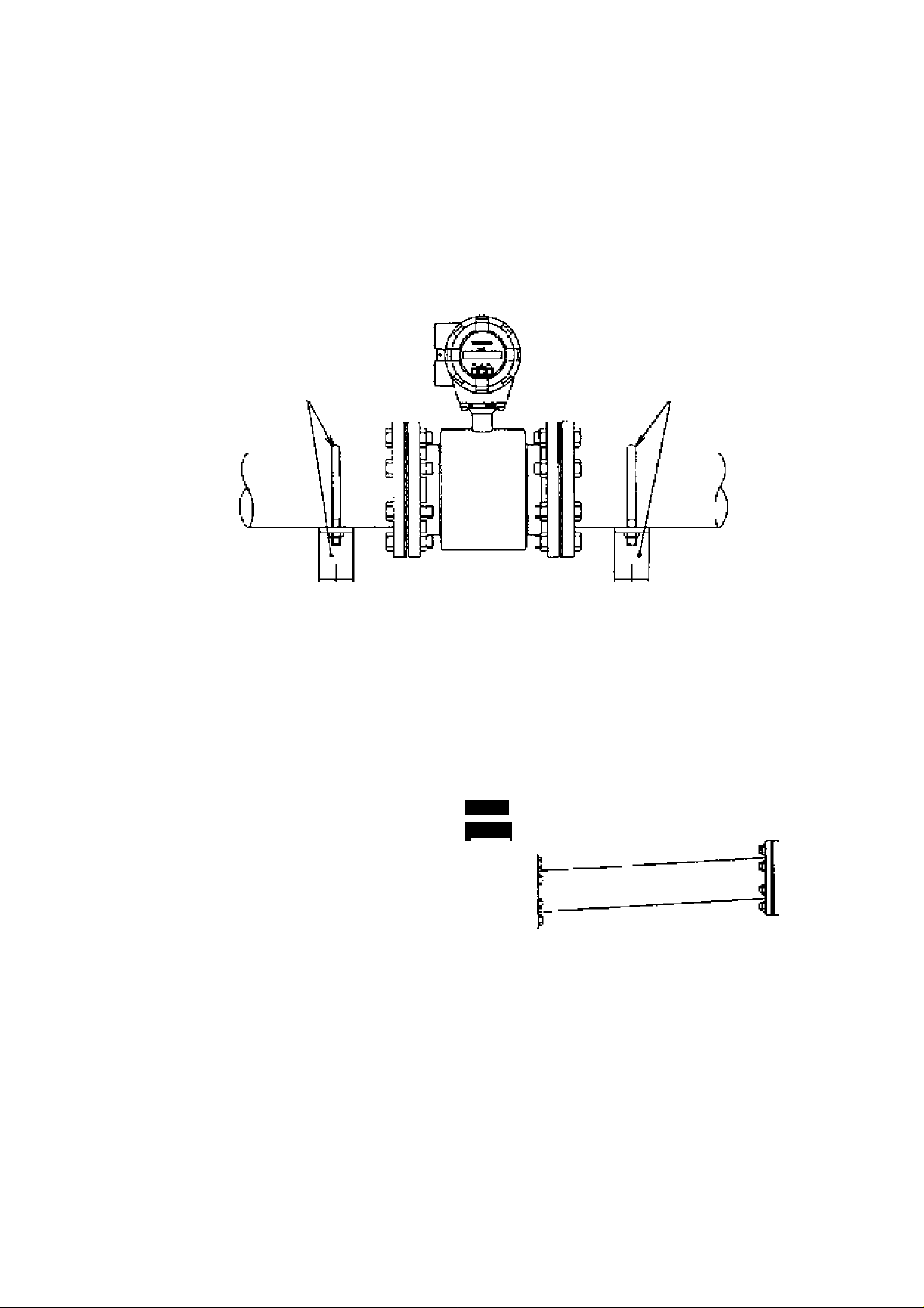
(5) Supporting Pipe
6.F8A0.770
Fix the relevant pipes Installed on both sides; of the detector by attach fittings, etc. to support
the pipe,
to the pipes by the dectmmagnctic flow'metcr’s weight and the fluid ma5;s. And it protect
from fluid leakage at flange face (sec Figures 4.8 and 4.9),
By
supporting the pipes, not only the pipe vibration is reduced but also the damage
Pipe support fittings
/////^//////////////////////////
Pipe support fittings
Figure Example of Hpe Fixing Procedure
K'5-5!
t
-flii
7777////7/777777777777777777777777777777777777777777777777777777~
Figure 4,9 Moclel Diagram of Unsuppuried Pipes
- 23 -
Page 25
TOSHIBA
6F8A.07 7 0
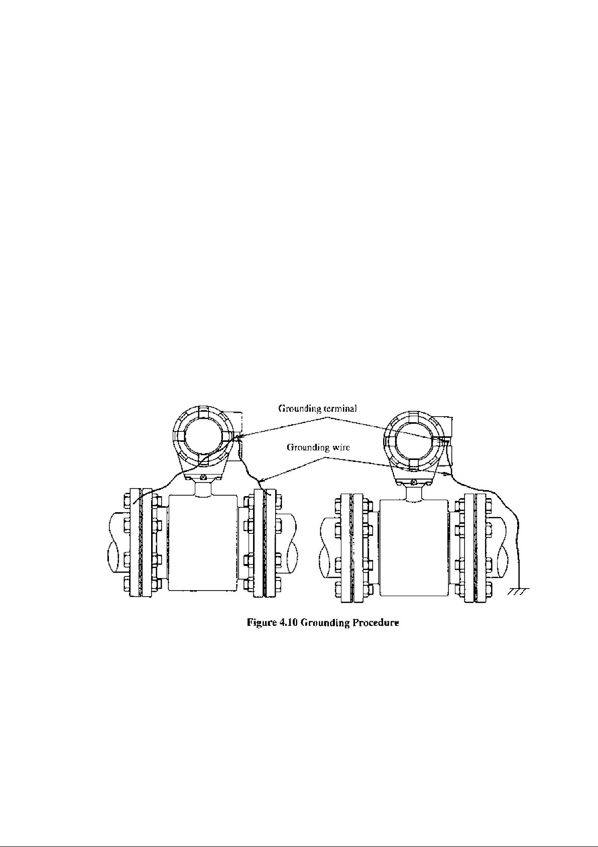
(6)Gruunding
The grounding [ermin^l of ihc Ll'434/Lh4t)4 flowmeter ithould be grounded with 100 ohm
or less ground resistance. Use a heavy copper braid or wire (cross-sectional area mm"
minimum) to ground the terminal anJ make it as shon as possible. The terminal is M4 size
and an M4‘sizc crimped ring lug should be used to connect the wire to the terminal. Avoid a
common ground where earth current may flow, An independent ground is preferable. Sec
Figure 4,li), for a conductive pipeline grounding and non-cjondactive pipeline grounding
procedures.
To prevent a two-poinl grounding, ground the shielded cable on the receiving instrument
side.
I If connection pipe is conductive:
Connect between the grounding terminal
and both ends of the mating flanges with
a heavy copper braid or wire
(cross-section 5,5 mm" minimum).
If connection pipe is non-conductive;
L’se H heavy copper braid or w ire
(cross-scction 5.5 minimum) to
ground he terminal w'jth 100 ohm or
less ground resistance.
- 24 -
Page 26

TOSHIBA
5. Wiring
A WARNING
DO NOT DiSCONNfXT WHILE CIRCUIT IS LIVE UNLESS
LOCATION IS KNOWN TO BE NONHAZARDOUS*
Live pari of eleciric circuit or a high tempeniiure deparimciit can
0
DONT
Do not live circuits While assembly of all componems not over.
cause explosion.
6F8A0770
0
DON’T
I
Jnstail per the National Electrical Code for Che US (NEC, ANSI/NFPA 70)
and the Canadian Electrical code for Canada (CEC, CAN/C5A-C22,1)<
O
DO
Protective performance degradalioii fur haiiarduus lucalion can
cause explosion.
Unsuiiable conduit connections for hazardous location can cause
explosion.
A CAUTION
■ Do not work OR piping and >viring
with wet hands.
Wet hands can cause system
0
DON’T
■ Do not modify or disassemble the
LF434/LK4fl4 unnecessarily»
t this product can cause elec-
DON’T damage TO ihis product»
■ Use the proper cables for wiring of
power and I/O <
/ J \ tern failure or damage and
failure.
Modifying or disassembling
trie shock, malfunction of or
Using a cable other lhan the
one specified may cause sys-
mav break, waterproof.
■ Ground the LF434/LF404 properly.
Operating this product wilhoul
o
DO
■ Prepare yourself for the cable glands
which could l>e used in Division 2
hazardous locations»
DO
A
a grounding can cause system
malfunction.
Tite apparatus should not be
provided with the cable glands.
The label shown left is placed
near the terminal board for
power input.
Be alert to electric shock.
- 25 -
Page 27

TOSHIBA
6F8A0770
Howmeter accuracy mfiy be affected by the way wiring isS executed. Proceed witii w-iring
taking the following precautions:
(1) Select the cable runs away from electrical equipment (motors, transformers, or
radio transmitters) which causes eleciromagnciic or dcctrosiatic interference.
(2) Deterioration of llow^meter drcuil insulation occurs if the converter interior or
cable ends get wet or Ituniidilied. This in turn causes malfunction of flowmeter
or noise problems. Avoid a rainy day if the flow meter is to be installed outdoors.
Even indoors^ prevent water from splashing over ihc flowmeter. Try to finish the
wiring as quickly as possible
(3) The converter has a surge-absoit>ing barrier installed inside. Therefore, do not
conduct a withstand voltage test for the converter. J o check the insulation of the
converter, use a voltage of 250 V dc or less.
- 28 -
Page 28
TOSHIBA
5Л Cables
Use the kind of ciibles shown in Tahle lo wire the converler.
Table 5.1 Cables
Name Cable type
Power cable
1/0 cable I'he number of wires for the output cable depends on Ihc
Notei Use a four-wire cable if the arresters are to be used. See Figure 5.1 below,
5.2 External Device Connections and Grounding
The terminal board connections of the LF434/LF404 flowmeter arc shown in Figure 5.1.
Proceed with wiring as described in Section 5.4, '‘Wiring Procedure.”
Three-wire sheathed
cable (Note)
system spccificiirions. Use a shielded cable with nominal
cross-scctional area of 1.25 inrii^ and overall diameter of
n to 13 mm.
Nominal
cross-.sectional
area
2
mm^
6.F.8A07 7 0
Overall diameter
11 to 13 mm
If power supply is specified as DC, use M as positive (+) and 1.2 as negative (-) terminals.
Instrument Panel:
ordered separately
■; Cument output (4—20 mA dc)
Plown-fceler
[C1 |~1^Трс|51с|[сОы[ ni|oQ^noi| -
’ ■ \
IV wire
5.5тзп"
or more
*^1 To use the arresters, ground the ON 13 terminal using the wire shown in broken line.
*2 Locate an external double-pole power switch on the power line near the flowmeter and within easy
operation. Mark one the switch as the tlisconnecting device for the flow^meler.
Use an appropriate switch of the rating shown below:
1/0 cable
R>wer cable
Recommended sw'itch rating; Rating 25D V ac, 6A or more
Inrush current 15 Лог more
- Digital Output I
; ■; r>igilai 2
: Digjiit! Input (20 to 30 V de)
*1
Cixrourided with 1 (X)Q or less
..........
! ground resistance.
— > Power Supply
It “"2 ^
Power Switch
Figci re 5.1 Term in a t В lock Connection s
- 27 -
Page 29
TOSHIBA
6F8A0770
IMPORTANT
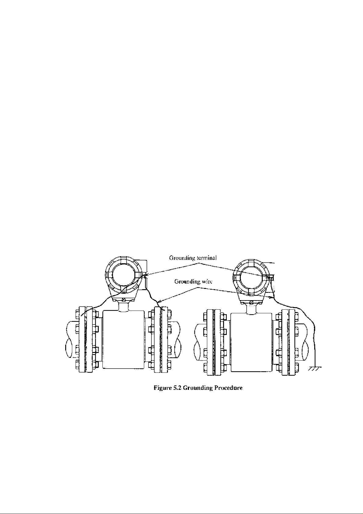
(1) The grounding terminal of the LF434/Lr404 ilowmeter should be grounded with
100 ohm or less ground resistance. Use a heavy copper braid or wire
(cross-sectional area .S..'? inm' minimLim) to ground the icrminaJ and make it as
short as possible, ITie terminal is M4 size and an M4-size crimped ring lug should
be used to connect the wire to the lermina!. Avoid a comirion ground where earth
current may flow'. An independent ground is preferable. See Figure 5,2. fora
conductive pipeline grounding and non-conductive pipeline grounding procedures.
(2) To prevent a tw'o-point grounding, ground the shielded cable on the receiving
instrument side.
I If conneetton pipe is conductive:
Conned between the grounding terminal
and both ends of the mating flanges with
a heavy copper braid or wire
{cross-section 5,5 mm" minimum).
If connection pipe is non-conductive:
Use u heavy copper braid or wdre
(cross-section 5.5 mm^ minimum) to
ground he terminal with 100 ohm or
Jess ground resistance.
- 28 -
Page 30
TOSHIBA
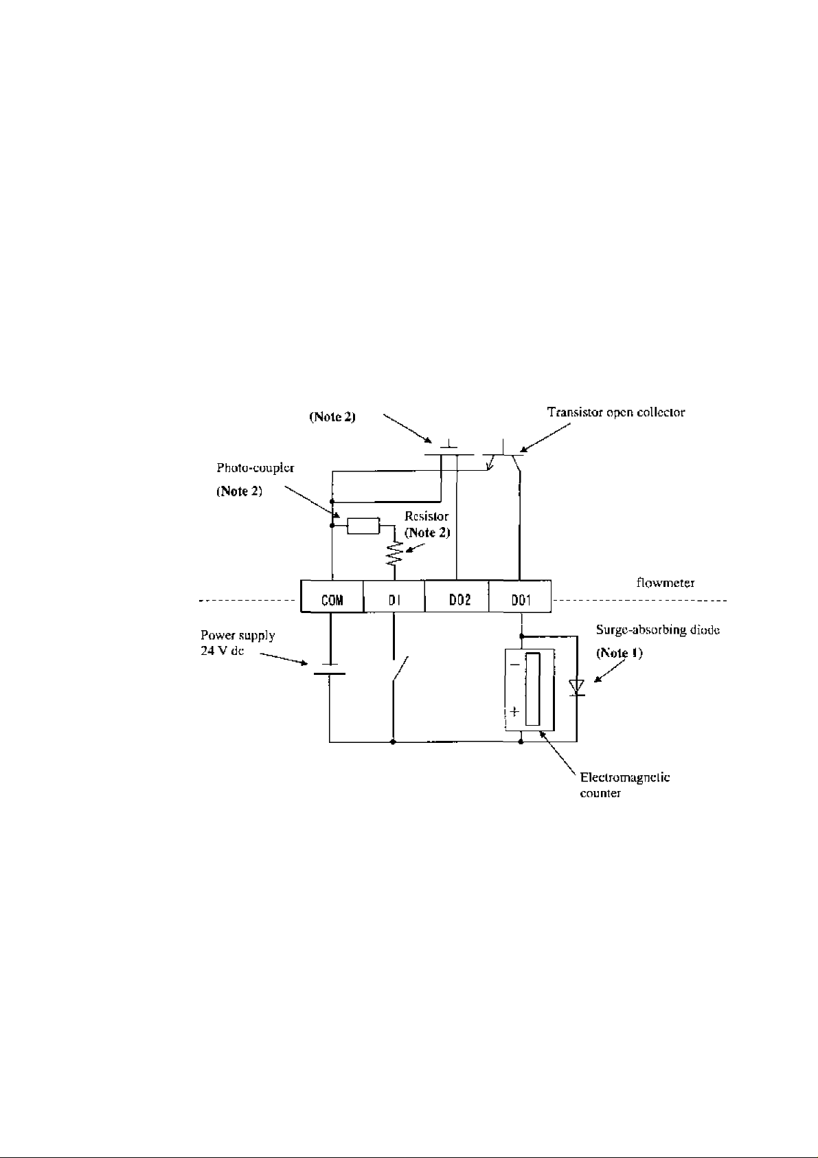
53 Digital I/O ConnecUons
Pigiial li O terminals consist of conti.ct output terminals (standard DOl and optional
D02), voltage signal input terminal (1)1, optional), and signal common terminal (COM),
Each terminal (DOl, D02 and Dl) is isolated from internal circuits, Terminal (COM) is
the signal common for the other three terminals (PC I, D02 and DI).
Functions can he assigned for each terminal with the LCD control keys (option). See
Chapter 10, “Digital t/0 Functions.’"
To ciinnect an electromagnetic relay or counter to the contact output terminal (DOl Or D02),
put a surge^absorbing diode into the input circuit of the relay or counter. See Figure 5,3 for
an example of electromagnetic counter connection.
6F8A0770
Solidbtate rchiy
Note 1; Use a surge-absorbing diode of the rating: current rating lA and voltage rating
200 V minimum.
Note 2; The Solidstaic relay, photo-coupler and resistor are not provided fiir the standard
model (the one with no digital I/O specifications), Leave the terminals for D02 and
Di open.
Figure 53 Electromagnetic Counter Connoction Example
- 2 9 -
Page 31

TOSHIBA
SA Wiring Procedure
5,4.1 Cable Termination
6F8AÛ770
Cable terminaLion Eind cabJe connections are described below.
âs CAUTION
■ Do not conduct w'iriitg work w hen
power is applied.
Wiring while power is ap-
( plied can cause eledric
shuck.
DON^T
■ Do not work on piping and w^nring
with wet hands.
Wet hands may result in
electric shock.
0
DON’T
IMPORTANT
The apparatus should not be provided wilh the cable glands,
Please prepare yourself for the cable glands which could be used in Division2 hazardous
locations.
Use cables as specified in Table 5,1. First. Remove the cable sheath about 70 mm from the
end to expose the coated wires and then strip the wires about 10 mm. Then attach an
M4’size compression terminal lug to the end of each wire using a compression looL The
compression terminal should be of Ihe kind with insulated sleeve to prevent shorts betw^een
adjacent terminals. The overall length of the wire with the terminal attached should be about
60 mm. See Figure 5.4 bdow'.
M4-sizc compression terminal lug
- 30 -
Page 32

TOSHIBA
5A2 Cable Connections
(1) Remove the housing cover for the terminal board shown in Figure 3.1. The lerminal board
6F8A0770
Connect rtie terminaled cable wires
IMPORTANT
Connect the wires securely to the lerminal board. A loose connection may result in
unsatisfactory ilowmelcr perform a nee. Make sure the wires are securely connected,
is located inside the converter as shown in Figure 3.2, Connect the crimped terminal of
each wire to the specified pin of the terminal board . Sec Figure 5,1 for the terminal board
configuration. Tighten each crimped terminal to the terminal board with a screw using a
Phillips screw-driver asshow-n in Figure Loose connection may result in unsatisfactory
flowmeter performance. Make sure the wire is securely connected.
i:y
ihe terminal board as described below.
(2) After the terminal block connection, pull the cable a little so that the cable runs .straight
from the terminal block without unnecessary w-inding.
(3) Attach the terminal cover and screw the housing cover for the terminal block. To keep Ihe
housing seal, tigliten securely Ihe cover using a tool fitting with the groove on the cover.
-
31
-
Page 33

TOSHIBA
6, Operation
6,1 Preparatory check
6F8A0770
A CAUTION
n Do not touch the LF434/LF404 maio body when
high temperature fluid h being measured«
The fluid raises the main
0
DON’T
hollow the proceclurc described bdo^v to prepare before starling the flow measuremem.
System Check
Check the wiring bciween the converter and related instruments,
Make sure all the boils of connection flanges on which the flowmeter is mounted
securely tightened.
Make sure the direction of flow arrow is in accordance with actual flow.
Make sure the flowmeter is grounded with ICO ohm or less ground resisiance.
Make sure the converter housing covers arc securely tightened.
body leinperaturc and can
cause burns when touched.
Placing System On-Stream
Let the fluid go through the detector pipe. When the detector is filled with the
fluid, stop the fluid and keep
Supplying Electric Power
Make sure the power supply is as specified.
Checking Converter Parameters
Check the configurntion paramcicr settings. Refer to Chapter 7, "‘LCD Display
and Controls,” Chapter 8, ‘"Configuration Parameter Setting,and Chapter 11,
“Commiinications Eunclioii,”
Zero Adjustment
Wail for 30 minutes to warm up the flov-mieter. Then making sure the fluid holds
still in the detector pipe, starts the zero adjustment.
Refer 10
On-line measurement
Alter checking the items and conducting the zero adjustment as listed above, let the fluid go
through the detector pipe. Output (4-20 iriA dc) directly proportional to the flow' rate can be
obtained.
62 ,
“Zero Adjustment.”
it s ti ll ¡n
the detector pipe.
- 32 -
Page 34

TOSHIBA
6,2 Zero Adjustment
6F8A0770
To conduct /oro adjustJiieitl of the flowmeter, iho fluid in the delector pipe must be held still.
There arc three different ways to slatl the zero adjustment:
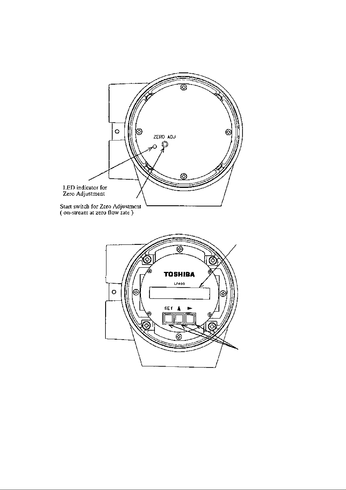
(1) Pressing the zero adjustment switch for the model without LCD display
(2) Pressing a combination of control keys for the model with LCD display
(see 8,2-ii, "Zero Adjust men I'')
(3) Sending a command signal from a HART communications device
(such as the AFIOO hand-held terminal),
The following is the procedure for starting the zero adjustment for the model without LCD
display,
■ Press the zero adjustment switch for more than 3 seconds.
(Note that once the 7ero adjustment is started, there is no way to cancel the zero
adjustment sequence.)
Then the Li3D indicator lights and the zero adjustment sequence will start. The zero
adjustment sequence lasts about 3 to 6 seconds, (Zero adjustment duration depends on
the excitation current frequency. It lakes about 3 seconds for 24 Hz selling and about 6
seconds for 12 Hz and 6 Hz settings.)
When the zero adjustment sequence ends, the LED indicator goes off.
I’o conduct the zero adjustment, it is necessary to open the cojtverter housing cover for
internal electronics and press the switch. Observe the following precautions w'hcn you
open the housing cover:
(1) Do not open the cover in the open air unprotected against rain or wind.
If yon adjust the flowmeter in ihe rain, this can cause electric shock or damage to the
llow'meler electronics. If wind blow's against the internal circuitry of the converter, output
may flticttiate and fail to indicate correct measuring values.
(2) Do not conduct the zero adjustment when the ambient humidity is higli. By opening the
cover in high humidity conditions, the measuring accuracy may be reduced or damage
caused to the flowmeter electronics.
- 33 -
Page 35

TOSHIBA
7. LCD Display and Controls (option)
You can select the operation mode, change the configuration parameters or execute
operation-specific functions using the control keys on the panel. How to operate these
keys is described in this chapter.
7,1 Outline
The LF404 Converter lias an optional LCD display. The LCD display can be used to set and
jrdicare various configuration parameters. Figure 7.1 shows the front view of LCD display.
(1) Do not open the housing cover for LCD display in the open air unprotected against ruin or
wind. If you open the housing cover for LCD display in the rain, it can cause electric
shock or damage to the flowmeter electronics. If wind blow-s against the internal circuitry
of the converter, the output may fluctuate and fails to indicate correct measuring values.
(2) Do not open the housing cover for LCD display when the ambient humidity is high*
liy opening the cover in high humidity conditions, the measuring accuracy may be re
duced or damage caused to the flowmeter electronics.
6F8.A077 0
Housing cover for
^LCD display
Figure 7.1 LF404 Converter with LCD display
LCD display
A 2-linc X 1 h-characier liquid crystal display. The backlit display enables an easy4o-rcud
indication even under poor lighting conditions. Instantaneous flow rates or totalized flow in
the measurement mode, or configuration parameters in the setting mode can be displayed.
- 34 -
Page 36

TOSHIBA
■ Control Keys
Functions of each control key when pressed are shown in the table below.
6F8A0770
Changing the opefiition mode, checking or changing parameters can be done with thej^e keys,
To operate these keys, yon have to open the converter hotising cuver. Observe the following
precautions when you open the housing cover:
Control kevs
SE T
□
▲
□
Basic Functions of control keys
(jocs inii> the items selection scqucnec.
10.00 (iv/s Л1:ЕХ. CdRR
100.0 %
Goes into the detailed-item specifying sequence for each selected ¡tent in
A1:EX CURR.
bcicctioa iiequcncc
Stores ihe sclccteLl tljita in the setting mode.
B1:UNIT 1
%
status tif changing the data status of iinish changing
Changes items (alphabet letter and iminherj in the items selection sequence,
and change.«, parameters (iiuniltcrs and.^'or units) in the detailed-ilem specifying
OZiRAUGE 1
02. DOO i/s
datc:0.2f)Q0m/s
Starts and stops t:ie totalizer in the mcasufcmccit mode. (Note)
F '000 ri''
00. 0 %
stop the totalizer Stan The totalizer
Changes digits {alphabet letter iind number) in the items seleclioir .scqiience,
and slarls the detniled'itcni S[>ecifying sequence by indicating the left-most
'
------
/
’—/
,—к
1—
1
----
\
1
-----
\
1—/
sckclion scqaciicc '
A1:EX. CURR.
0. гюоА
Bl:UK!T 1
%
C2:fiANGE 1
03, 000 ffl/s
F IODI C
100. 0 \
------
/
D1: DAMPING
00. 5 S
Cl ; COUNT RATE
1. 2JE-'^ iD^
Indicate cursor under '2'
0
100. 0 %
reset the totalizer
Dl: OA^PIPIG
OQ. 5 S
setting mode status of finish changing
Moves the cursor from kf( to right (from the right end reverts to the left end) in
►
□
Note: To opcrsrtc ihe totalizer, it is prefern bJe to set the indicating unit (UNIT 1 tmd.'br UN IT 2)
to one of the units appropriate for totalization just to make sure it is operating correctly.
See 1(1.2, ‘^Totalizer and Pulse Output,”
ihc above sc<uicrux.
Gl: CCUNT RATE
1. Z2Ì-A n-
[ndicalD ourstjr umler ‘ I ’
Rescis the lotjlly.cr in Ihe measurement mode. {Note)
F lODO
-
_________
100. 0
%
sfnrt the totalizer
35
-
1—\
'
Page 37

TOSHIBA
12 Display Format
6F8A0770
In Ihc mcdAurcment mode> measured dala are displayed in UNH’ I (primary indicating uniO
and UNIT 2 (secondary indicating unit). As to indicating units, see 8,2.4, '"Indicating Unit
Display Format
Displayed in UNIT I indicating unii.
I— “C is indicated when lota) flow is counted.
i
___________________________
10 0,0
_______________
%
Measured Value Display Format
(1) Flow rate
____
Upper 4 digits ma^iimum arc effective (for the selected span).
r
yr:F 1 0 0 0 0 0
.. .. J
___
[ he unit of time
■The unit of flow
7 digits (9999999) maximum including decimal
I c
*
(
_____
..
Displayed in UNIT 2 indicating unit
C is indicated when
communication is in progress.
- 36 -
point
Flow direction: Forward “ (blank space);
Reverse
Page 38

TOSHIBA
6F8A077.0
(2) Totiìlìzer
I 1 l_L
9 9 9 9 9 9 9 9 C
........................
....
.......................
(3) Volumetric flow
F 9 9 9.9 9 n I C
.......................
....
I I , I I I I 1 I I
^ LJ
- “C’ is indi cateti wben total llow is counted.
Jnerements per counting rate. Refer to
H.2 10, “Counting Rate/"
Wraps around after 999^999?.
for forward and "R"' for reverse direction flow
will be displayed
Displays down to the smallest digit of courting rate,
•- ' C" is indicated when volumetric flow is counted.
— The unit of flow
8
digits (99999999) maxinium including decimal
point
If tjtc flow count exceeds 99999999, wraps around.
(4) % display
"10 0,0 15
.
............................
Ill
“F" forfonvard and “R'* for rcvcr.se direction
flow will displayed.
Displayed down to 0,1
Displays tip to 125,0 %.
i'low'direction: Forw'ard “ (blank space);
% .
Reverse
-
37
-
Page 39

TOSHIBA
7 J Basic operations
6F8A0770
Flow mea^surcjncni in Ihe measurement mode, checking or changing configuration
parameters in ihe setting mode and a converter unit check in the calibration mode are
the basic operations of the LF404 converter*
7*3*1 Müde Change
The 1.F4(I4 converter has three operation modes: measurement* setting and calibration.
The system slays in the measurement mode after the power is turned on* To change (he
mode to the setting or calibration mode, press [SRT] and select the desired item using
[ ► ] and [ A ] keys. To return to the measurement mode, select “0" {MEASURE
MODE) for the number column of configuration items (such as AU or B[)). See 7.4*
“Configuration Items Selection Table,"
■ Measurement mode
: measures ttic process flow and displays and outputs the measured process values. The
flowmeter can measure the flow velocity, flow rates* or totalized flow. I’he flowmeter
first goes into this mode when power is turned on.
Setting mode
: used to check or change various configuration parameters used in the measurement
mode. These parameter values are displayed while checking or changing ihe.se values
but the flowmeter outputs the Tieasured process values as in the measurement mode.
See 7,4, “Configuration Items Selection Table" and 8.2, “Checking or Changing
Parameters" for details. Configuration items are from Al, A2, A3 to Ml.
Calibrtttion mode
: used to check the converter iniernal circuits. The internally generated simulation signal
is used to check the measuring span and excitation current value. The current output of
the flowmeter changes in acoŒtlance with the simulation signal. The stains of each
digital output is held to the value just before the system moved into the calibration
mode. Sec 7.4, “Configuration Items Selection t able" and Chapter 9, “Calibration" for
details. Configuration items are from N1 to N4,
- 38 -
Page 40

TOSHIBA
Change mode flow
SHT ^ ►
□ □□ are shown lo conirol keys, and LF4f)4 display is changed to
Measureineni mode
-------------
6F8A0770
^ indicEited.
- 39 -
Page 41

TOSHIBA
Key o)>erntion Display example Description
6F8A0770
7.3.2 Configuration Parameter Selection in Setting and Calibration Modes
Process as follows to select the desired items, to check or change the item setting value.
B Tu selects the desired item ;
SFT
□
▲
□
►
□
□ □
10. 00 m/s
100.0 S¡
Al; EX. CURR.
B1: UNITl
Bl; UNITl
C2; RANGE 1
Measure value displays .(Me a suremento mode)
l*ressing [Sti'fJj the system changes to the items
selection sequence. (Note)
And the cursor appears under alphabet (A).
Change the alphabet to “B” by pre.ssing [ -^ ],
* If cursor is the number, the number is increased
by pressing [-^ ],
Then move the cursor to the number by pressing
[ ► 1
* If cursor is the number, Ihc cursor is
changed to the alphabet by pressing
Selects the desired item (indicated by an
alphabet letter and a number) first by selecting
the digit (alphabet or number) with [
then changing the value w^lth [ ^ ].
The example shows “C2: RANGE 1
\ > ] .
> ]
and
Note: In case of that the convrter is type for special specifications and serted password,
changing measurement mode lo items selection sequence, password-input mode appears.
Sec 7.5’Tassword Inpul'Tor details about Password-input mode
See 7.3.3 '^Converter for Special specifications'Tor to differentiate the converter for
special specifications and normal.
-
40
Page 42

TOSHIBA
6F8A0770
To change the setting value:
Key operation
□ □
SET
□
►
□
Ж .
i □
►
□
Dhplay example Description
items selection sequence displays.
C2: RANGE 1
C2: RANGE 1
02. 000 m/s
C2; RANGE 1
02. 000 m/s
C2: RANGE 1
n.
000 m/s
C2; RANGE 1
12. 000 m/a
Selects the desired item (indicated by an
alphabet letter and a number) first by selecting the
digit (alphabet or number) with [ ► ] and then
changing the value with [a. ].The example shows
“C2:RANGT 1’^
Press [SET] to select the desired item setting
value. And the cursor disappears and the item
setting value displays.
You can check it.
Pressing [ ► ], the cursor appears.
Parameter changing sequence
Change the value by pressing [ a ].
rhen move the cursor to another digii by pressing
i ► ]■
□ □
1 ó
▲ ►
SLT
□
SET
□
C2: RANGE 1
05. 000 m/s
C2: RANGE 1
05. 000 m/s
C2; RANGE 1
02. 000 m/s
02 :
RANGE 1
05. 000 m/s
Change the value by pressing [-^j, ITicn move
the cursor to another digit by pressing [ ► ] and
change the value.
In this example repeat this process until the
display shows “05. OOOm/s
By pressig [SET], flickers the selected value tu
confirm changes made for the selected item.
By pressing [-^j, In return to the parameter
changing sequence.
By pressing [SET], stores the indicated value and
Slop flickering of data.
-
41
-
Page 43

TOSHIBA
Key 0 pera É ion Display example Description
6.F8A0770
To ri^turn th£ meu^urement value:
1 □
□ □
SET
n
►
□
▲
A ►
C2: RANGE 1
0. SQOO m/s
C2: RANGE 1
C2: RANGE 1
C3: RANGE
CO; MEAS, MODE
2
Checking Ihe selling vuloe or after seiteci the
value.
By
pressing [SET], return to the items sdectioii
sequence.
Items selection sequence displays.
Then move the cursor to the number by pressing
[ ► ]
* [f cursor is the number, the number is changed
to the alphabet by pressing [ ► j,
Change the alphabet to *‘B'’ by pressing [ a j.
* If cursor is the number, the number is
increased by pressing [ a j,
By pressing [ ► ] and [ a j, select
‘^0;MEAS. MODE’’
The example shows "'C0;NEAS. MODE’’
SE T
□
10, DO m/s
100. 0
%
- 42 -
Pressing [SET], returns to mcasuremeiu mode.
Page 44

TOSHIBA
6F8A0770
7.3.3 Converter for Special spedtlcalions
The converter for special specifications is added some setting parameters. To
differentiate the converter for special specifications and normal, remove housing
cover for the terminal board shown in Figure?,2. The converter marked as shown
in Figure 7.2 is for special specifications, and nor-marked is normal.
The added setting parameters are following items.
{!) Password input/setting
(2) 4-20mA alarm out setting
(3) Dl detective level setting
{4) Preset function
See 8.2, “Checking or Changing Parameters'’ for details.
Example: F400 0И2
Figure 7.2 LF4D4 Converter for special specifications
- 43 -
Page 45

TOSHIBA
lA
Configuration Items Selection Table
6F8A0770
In the selling and calibrEilion modes, configuration items can be selected as shown below, For
example, the excitation current can be selected by the item AL To change ihe parameters for
ibe selected items, see the following chapters, To return to the measurement mode, select‘‘0’'
for the number (such as AO),
Setting mode items (Al, A2, A3 to Ml): Sec Chapter S, ‘‘Configuration Parameter Setting,"
Calibration mode item (N1 to N4): See Chapter 9, “Calibration.”
0 1
A
n
*1
B
C *1
D *1
"1
£
^1
F
^1
G
H *1
I *1
*1
J
*1
K
L *1
*1
M
*1
N
Escilaiioti Cur
rent *2
Indicating
Unii 1
Range I’ype Range 1
Daniping
Constant
Zero
Meter Size
Incl ¡eating
Unit 2
Ijdw Cutoff 4-20 inA Alin.
2
"2
*2
3
Excitation Fre
quency
*2
Range 2
Ouiput
*2
Adjustment
DQl Function *2D02 Fuiictio]] *2DI Function
C.^ounling Kate
Preset Count
High AloTin Set
Empty Pipe
Alarm
Rutc^tj^
change Lindt
Fixed-value
Output
*2
" 2
*2
*2
False Width
Presel Fuiict
*2
High Alarm
Value *2
Control
Limit Time
Fixed-currem
Outpu! ’2
^2
Low AJam Set *2Low Alarm
Fixed-pulse
Outpal *2
Zero Offset
Adjustment
*2
J’low Rate
Sig 50% ^2
Flow Rate
Cal 100% *2
Flow Rale
Cal [}%
Passwoni
Range 3
*2
DOI Alarm
Active Set ^2
*2
Value
Fxciling
CTurrcnt Check
4 S 5
"2
Range 4
"2
D02 Alarm
Active Set
*2
**2
*2
Range
Hysteresis *2
Dl Dct.lxivd
*2
*1: Returns lo the measurement mode.
®2:Passw'ord-protected parameter
Note: “A4:Password’, ' rB:4‘20Alm.OutT6:D1 Dot.Level ^ and ”H2;Presc( Funct” are added
parajneiers in the converter for special specifications.
- 44 -
Page 46

TOSHIBA
7*5 Password input
■ Т» input password:
Key operation
6F8A0770
l*as$word input is added parameters in the converter for special specifications (refer to
7.3.3 “Converter for Special specifications”). Only in case of the converter for special
specificationsT read this seciion,
The converter for special specifications have the password .That protects from calibrating and
changing part of parameter that influences measurement..
See 7,4 "Configuration Items Selection Table ” for details of password-protected parameter.
* See S 3.17 ‘‘Password” for password setting,
^Setting ‘000' to the password or the normal converter (sec 7.3,3 "Converter for Special
specifications"), password input mode does not appear and all configuration paraEuetcr
and calibrate can be changed.
The following example shows how \o input password ,123.
Display example
Description
SET
□
□
□ □
SET
SET
□
10. 00 m/s
100. 0
%
PASSWORD 1NPUT
000
PASSWORD INPJT
m
PASSWORD INPUT
100
120
123
PASSWORD INPUT
123
Al: EX CURR.
Measure value dispJays.fMcasureniCTUo mode)
Pressing [SHT], password input mode and the
cursor appears.
Change the value by pressing [ ^ j.
Move the cursor to another digit by pressing
[ ► ] and change the value by pressing [ a ].
in this example repeat this process until the dis
play shows “123,"
Pressing [SET], the cursor disappears and the
changed display flickers. Press [SET) again to
input the value.
Whether input password agrees or dose not agree ,
the items selection sequence, “Al :EX. CURR“ ap
pears.
But if input password does not agree, you can not
change setting parameter and calibrate.
Sec 7.4 "Configuration Items Selection Table” for
details.
- 45 -
Page 47

TOSHIBA
8, Configuration Parameter Setting
8.1 Configuration Items
To check or change parameters, first select the desired configuration item as described in
7,3,2. The configuration items arc listed bdow. See each section for detailed procedure.
6F8A0770
Section
8.2.1
8.2,2
8.2.3
8.2.4
8.2.5 Range I’ype
Configurr^Cion item
ExcUmion Current
Meter Size
li:xcitalion Freiiuency
Indicating unit
Span (range)
Hysteresis
8.2.6
8.2.7
8.2.S
8.2.9
8.2.10
Damping Constarli
Low Cutoff
Zero Adiustmenl
Digital I/O
Counting Rate
Pulse Width
8.2.11
8.2,12
Preset Count
lligh/low Alarm
Alarm Limit Value
8.2,13
8.2,14
Empty Pipe Alarm
Rate-of-change Limit
Control LiiTiil Time
8.2,15
8.2,16
; 8.2.17
8,2,18
8.2.19
8.2.20
Fixed-value Output
Zero Offset Adiustmeiit
Password *
4-2ymA Alarm Output
D1 detective Jjivel *
Preset Function *
^ A4: Password”D3'4-2(}AJ.M,OUT’Tfi'DI DETJd^VFi;\ and ’H2;PRbSb'I
Display example Page
Al; EX, CURR. 0. ZlOO A
A2: METER SIZE
A3: EX, FREQ.
Bl: UNIT 1
Cl: RANGE TYPE
C2: RANGE 1
C6: RANGE HYST
Dl: DAMPING
D2: LOW CUT 05, Û
El; ZERO ADJUST.
FI: DOl FUNCT. 1 : H ALM
GI: COUNT RATE
G2: PLS, WIDTH
HI : PRESET COUNT 00009000
11: H, ALARM SET
12 : H. ALARM VAL
Jl: EMPTY ALM
K1: LIMIT RATE
K2: LIMIT TIME
LI; FIXED OUT OFF
Ml: MANUAL ZERO
A4: PASSWORD
D3; 4-20 ALM OUT
F6: Dl OET, LEVEL
HZ: PRESET FUNCT D:H0LD
50 nun
24
H;
1 :SINGLE
01. 000 m/s
05, 0
%
05. 0 s
%
0. 1
%
6. OOE-ll
020 ms
+ 100.0
%
0;0FF
05. 5
%
01 s
-000, 1 %
123
1:4. OmA
1: H LEVEL
n/s
ON
73
76
78
81
84
87
91
93
97
99
101
47
49
51
.53
57
65
67
69
70
FUNCl" arc added parameters in the converter for special specifications (refer to
7.3.3 “Converter for Special specifications'’). The normal converter docs not have
these selling parameters.
’ 46 -
Page 48

TOSHIBA
8.2 Checking or Changing Paramctm
6F8A0770
8.2.1 Excktalion Current
Proceed iiii follows ui check or change the cxcilution curreju setting value.
■ To check the exciting current setting value;
Key operation
SET
□
SET
□
Dispiay example Description
Press ISHT] first to start the items selection sequence
A1: EX. CURR.
0. 21QDA
A1: EX. CURR.
and select Al; EX, CURR froiri arnung the
configuration items using [ ] and [ ▲ ] keys.
'[’hen press [SEP] again to dispiay the exciting
current setting value.
Pressing [SE'F), the system returns to the items
iselection sequence.
- 47 "
Page 49

TOSHIBA
IMPORTANr
The exciling current vitlue h faclory set when shipped. Do not change the value unless the value
differs from that writien on the nameplate of the fiowmeter
6F8A0770
'J\) change the excitation current setting value«
The following example shows how lo change ihc excitation current setiing value
fromC.l900AtoO,2150A,
Key operation
SET
□
►
□
^ ►
n
SET
□
SET
□
Display example Description
Press [SET] first to start the items selection
Al: EX. CURB,
0. 19D0A
Al: EX. CURB.
g. 1900A
Al: EX. CLRR.
0, Z90QA
Q. 2100A
0. 2150A
Al : EX. CURR.
0, 2150A
Al: EX. CURR.
sequence and select Al: EX, CURR from among
(he configuration items using [ ► ] and [ a ] keys.
Then press [SET] again to display the excitation
current setting value fO.1900 A in this example).
Pressing [ ► ], the cursor appears. Then press [ ► ]
as many times as necessary to move the cursor to the
digit to be changed.
Change The value by pressi ng [ a ]. TTien move the
cursor to another digit by pressing [ ► ] and change
the value. In this example repeat this process until the
display shows “0.2l.i0A.'' (Note)
Pressing [SET], the cursor disappears and the
changed display flickeri. Press [SET] again to save
the value.
Pressing [SET], the system returns to the items
jielection sequence.
Note: The valid range is from 0.0500A to 0,2300A, Tf you try to set the value above
0.2400A, the error message * H. OVEK SPEC appears. Set the value w'ithin the valid
range.
- 48 -
Page 50

TOSHIBA
8*2*2 Meter Si/e
Key operation Display example Description
6F8A0770
Proceed as iollow's to check or change the meter size of the detector.
■ To check the meter size:
SET
□
SHT
□
AZ: METER SIZE
50 min
METER SIZE
Press [SET] first [0 start the items selection sequence
and select A2: METER SIZE from among the
configuration items using [ ► j and [ ^ ] keys Then
press [SET] again to display the current meter size.
Pressing [SET], the system returns to the items
selection sequence.
- 49 -
Page 51

TOSHIBA
IMPORTANT
Meter size is factory set when shipped. Do not chfnigc the meter sii^e unless it differs
fram the specified value.
6F8A0770
To change the meter size:
The following example shows how to change the meter size from 50 mm to 100 mm.
Key operation
SET
□
►
□
□
SE T
□
SET
□
Display example DeiiCription
Press [SET] first to start the items selection
AZ: METER SIZE
SO mu
A2: METER SIZE
SO nn
AZ: METER SIZE
100 mm
A2: METER SIZE
100 itn
A2: METER SIZE
sequence and select A2: MEITUISIZE from among
(he configuration items using [ ► ] and [-a. ] keys.
Press [iiHT’J again to display the current meter size
Í50 mm in this example).
Pressing [ ► j, the cursor appears.
Select "T(X) nun” by pressing [ a ] as many times
as necessary. (Note)
Pressing [SE T], the cursor disappears and the changed
display flickers, Press [SE TJ again to save the value.
Pressing [SET], the system returns to the items
selection sequence.
Nole: The meter size is changed as shown below by pressing [ ^ ].
-► 2,5 mm 15mm-^LUi)mm 6fH)mm^0.1in 0,5 in ^4 in- ■ 24 in
If the meter si/e has been changed, other setting values (such as span and counting rale)
will be affected depending on the measuring unit used. Therefore, check those setting
values if you have changed the mctci size.
- 5D -
□
Page 52

TOSHIBA
8<2,3 Excitation Frequency
Key operation Display example Description
6F8A0770,
Proceed «s follows to check or change the excitation frequency.
■ To check the excitation frequency:
sr/r
□
SET
□
A3: EX, FREQ,
A3; EX. FREQ.
24 Hz
Press [SET] first to start the items selection,
sequence and select A3: EX. FREQ, from among
the configuration items using [ ► ] and [ a. ]
keys. Then press [SET] again to display the
current excitation frequency.
Pressing [SET], ihe system returns to the items
sdcolion sequence.
- 51 '
Page 53

TOSHIBA
6F8A0.770
To change the excitatLon frequency:
The excitalion frequency ciin be belecled from 6,12 and 24 Hz. The charaderistics of
tile flowmeier chnnge in accordance wiih the selected frequency as shown beJow', 24 Hz
is The default setting w 'he n shipped from the factory.
Excitation frequency
Zero point stability Good
Response lime
Fluid noise resistant
The following example shows how to change the excitation frequency from 24 Hz lo 12 Hz.
Key operation
SET
►
Display example
A3: EX. FREQ.
A3: EX. FREQ.
□
6 Hz 12 Hz 24 Hz
Description
Press [SET] first to start the items selection sequence
and select A3; EX. FREQ, from among the
configuration items using [ ► ] and [ a ] keys. Pre.ss
24 Hz
[SET) again to display the current excitation frequency
(24 Hz in this example).
Pressing [ ► ], the cursor appears.
24 Hz
▲
□
SET
□
SHT
A3: EX. FREEI.
12 Hz
A3: EX. FREÍ.
12 Hz
A3: EX. FREQ.
Select “12 Hz” by pressing [ * ] twice. The
excitation frequency changes as follows:
p d Hz -► 12 Hz -►24 Hz ^
Pressing fSE'I’j, the cursor disappears and the changed
display flickers. Press [SET] again to save the value.
Pressing [SET), the system returns to the items
selcdicm sequence.
- 52 -
Page 54

TOSHIBA
S.2.4 Indicating Unit
6F8A0770
You can seleci one ot Ihe 29 engineering units Jisted below as mt indicating unit.
• Now velocity: m/s, (fl/s)
• Flow rate: mVs» mVirrin, mVh, mVd
l/s, 1/min, 111, 1. d
ml/s, ml/min, ml/h, ml/d
(bbl/y), (bbl/min), (bbl/h), (bbl/d)
(gal/s), {gal/inin), (gai/h), (gat/d)
• Volumetric flow: 1, ml, (gai)
(totalized flow)
• Other units: COUNT (totalized flow without a unit), RANGE (1 to 4)
Code of volumetric
flow direction: F(fixed forward How), R(fixed reverse flow),
Bfautomatic selection bi-directional flow) )
Notes
1. Units in parentheses, such as '‘bbl”, and '■‘ft'’ arc show^n only when the meter si/c is
selected in inches. They arc not shown when the meter size is selected in mm.
2.
If COUNT or liANGE is selected, the display is shown as follows:
COUNT: displays totalized flew counts (8 digits) without a unit,
RANGE: displays the range number (1 to 4),
3. Only in case of the converter for special specifications (refer to
Special specifications”),
‘Time units /d, and flow rate units bbl/s, bbl/min, bb]/h, bbl/d, bbl can he selected,
‘Code of volumetric flow' direction F(fixcd forward flow'), R(fixcd reverse flow),
B(automaiic selection bi-directional flow) can be selected.
13 3
"‘Converter for
Two indicating units (primary unit: UNIT 1, secondary unit: UNIT 2) can be seJeaed.
Proceed as follow^s to check or change these tw'o indicating units.
- 53 -
Page 55

TOSHIBA
6F8A0.7 7 0
To check Ihe indicating unitui:
Key operation Display example
Sin'
B1 : UNIT 1
□
SET
□
Primary indicating unit and secondary indicating unit can be selected by the following
configuration items;
B1; UNIT 1 primary indicating unit
B2 : UNIT 2 secondary indicating unit
B1: UNIT 1
%
Description
Press [SE'T] first to start the items selection
sequence and select Bit UNIT 1 from among the
configuration items using [ ► ] and [ a | keys.
Then press [SET] again to display the current
primary indicating unit.
Pressing [SEl’l, the system returns to the items
selection sequence.
- 54 -
Page 56

TOSHIBA
6F8A0770
■ To chfinge the indicating unit (1):
The tbilowing example t^hows how lo change the primary indicating unit from % to iril/s.
Key operation
SET
□
□
A.
□
►
□
▲
□
Display example
Bl: UNIT 1
%
61: UNIT 1
%
Bl: UNIT 1
ml B
Bl: UNIT 1
il _ B
Bf: UNIT 1
mlA
Desciiption
Press [Sb'n first to start the items selection sequence
to select lih LiyiT 1 from among the configuration
items usirag [ ► ] and [ a ] keys Then press [SET]
again to display the current primary indicating unit
in this example).
Pressing [ ► j, the cursor appears.
Select “ml” as the first unit of primary indicating unit
by pressing [ ^ ] as many times as necessary. (Notel)
Pressing [ ► ], the cursor moves to the second unil
(time unit) of primary indicating unit.
Select "‘s” as the second unit (lime unit) of primary
indicating unit by pressing [ ▲ ] as many times as
necessary. (Note 2)
SET
□
SHI
□
Notes;! ,The first unit (volumetric unils etc,) changes as shown below:
Bl: UNIT 1
nl/s
Bl: UNIT 1
I
------
► ^ ]
RANGE-^
Units in parentheses, such as "bbr, ‘‘gaf’ and “ft'" are shown only when the
meter size is selected in inches. 'J hey are not show'ii when the meter size is
selected in mm.
2. The second unit (time unit) changes as shown below:
-► /s—/min
Pressing [SET|, the cursor disappears and the changed
display flickers. l*ress [SET] again to save Ihc unit,
Pressing [SE'l ], the system returns to the item
selection sequence.
---------
COU^T^ (ft/s)^
-------
►/li
---------
► ml
-------
/(! ----------
-> (hbl)'
----------------
-
55
-
Page 57

TOSHIBA
6F8A0770
I To chimge the indicating unit (2):
Only in case of ihc converter for special specifications (refer to 7J.3 "Converter for
Special spedfications"). Code of volumetric flow direction h’(fixcd forward flow),
R(fixed reverse flow), H(automatic selection bi-directional flow) can be selected.
In ease of normal converter, the code of volumetric flow direction does not appear.
The following example shows how' to change the primary indicating unit from F to R.
Key operation
SET
□
►
□
►
□
►
□
▲
□
Display example IJe.scription
Press [SET] first to start the items selection sec|uencc
Bl: UNIT 1
n' F
Bit JNIT 1
F
B1: JNIT 1
m* F
B1 : UNIT 1
n' F
Bl: UNIT 1
R
:o select Bl: UNIT 1 from among the configuration
items using [ ► ] and [ a. j keys Then press [SET]
again to display the current primary indicating unit (m^
F in this example).
Pressirtg [ ► ], the cursor appears.
Pressing [ ► ], the cursor moves to the second unit
dime unit) of primary indicating unit.
Pressing [ ► ], the cursor moves to the third unit
(code of volumetric flow direction) of primary
Liidicaiing unit.
Select *‘R” as the third unit (code of volumetric flow
direction) of primary indicating unit by pressing [ a ]
as many limes as necessary. (Note 1)
SET
Б1: UNIT 1
□
SET
Bl: UNIT 1
It' R
□
Notes. The third unit (code of volimetric flow direction) changes as shown below:
B
-------
Pressing [SET], the cursor disappears and the changed
display flickers. Press [SliT'J again to save the miit.
Pressing [SET], the system returns to the item
selection .sequence.
► F
---------
- 56 -
► R
-------
Page 58

TOSHIBA
8,2,5 Span (range)
(1) Rung« type
6F8A0770
You can set iLc following constanls in this setting item:
(1) , Range type
(2) . Spiin
(:!?)* Unit of span (can be changed only in range 1)
(4), Hysteresis
You can select a single range or multiple ranges. Select one from five types shown below:
Range type
1. SINGLE
2.
4F-0R
3. 2F-?R
4, EXT. 2F-0R
5. EXT. 2F-2R
Description
Single range
Unidirectional flow, automatic selection of multipk ranges
Bidirectional flows, automatic selection of multiple ranges
Unidirectional flow, multiple ranges selected by external signal
Bidirectional flows, multiple ranges selected by external signal
- 57 -
Page 59

TOSHIBA
(2) Span (range)
6F8A0770
■ SpHii can be set and displayed as follows for flow vdociiy and flow rales:
• blow velocity: OI .OOG m/s (three digits after the decimal point)
• Flow rales: 2.83E+3 mVU (three digits and exponential)
■ Valid range of span is U.l m/s to 10 rill's in terms of flow velocity,
If you try to set ihc span outside of this range, one of the following messages appears:
* K OVER SPEC- (it the set value exceeds 10 nv's)
* L OVER SPEC, (if the set value is less than 0,1 ni^s)
fry again to set the span within the specified range.
■ When multiple ranges arc used, tbc following must be observed;
* Range 1 > Range 2 > Range 3 > Range 4 (unidirectional flow, multiple ranges)
* Range 1 > Range 2, Range 3 > Range 4 (bidirectional flows, multiple ranges)
If you try to SCI the ranges not conforming to the above, the following message
appears:
♦ MULTI RNC ERR
Try again to set the ranges as .specified above.
■ 'I'ota I izat i on count i ng ra le
If you have changed the span while the counting rate is set for totalization, the
counting rale for 1(X)% output may have exceeded the maximum counting capacity.
In this kind of event, the following message appears and the sy.siem goes to the
counting rale setting sequence.
♦ H. OVER : RATE or L. OVER C RATE
Set the counting rate (See S.2.1 (/"Counting Rale’')for the newly set span*
- 58 -
Page 60

TOSHIBA
(3) Unit of spurt
6F.8A0770.
One of the following engineering units as a unit for the span can he selected. The unit is sci
for the range 1 and the same unit applies autoinaiiealiy to other ranges—range 2, range 3
and range 4,
* Flow veloeUy: lo/s, (ft/s)
* Flow rate: rnVs, mVmin, mVh, mVd
1/s, 1/min, L'li, 1/d
nifi's, rnl/min, ml/Jt, ml/d
(hbl/s), (bbJ/min), (bbJ/h), (bbl/d)
(gal/min), (gal/h), (gal/d)
Units in parentheses, such as "bbr, "gal” and “ft'’ arc shown only when the meter si/e is
selected in inches. They are not shown when the meter size is scJecied in mm,
if you change the unit, the new span based on the newly set unit will be automatically
displayed,
fJnly in case of the converter for special specifications (refer to 7,3.3 ' Converter for Special
specifications”), l ime units /d, and flow rate units bbl/s, bhl/miii, bbl/h, bbl/d, bbl can be
selected.
59 -
Page 61

TOSHIBA
{4) Hysteresis
6F8A0770
TTie hysteresis is the dead band used when multiple ranges are switched. The hysteresis can
be set from 0 to
automatic selection of multiple ranges is used.
[The setting sequence]
'The following is the setting sequence of span (range),
25 %
in increments cf 0J%. The hysteresis setting is needed only when
If multiple range is selected, compulsory range I to range 4 and hysteresis settings are
displayed.
- 60 -
Page 62

TOSHIBA
Key operation Display exarnple Description
Proceed as follows to check or chfingc each cansLaitl,
I To check each constant:
Press [SET] first to start the ilcms selection
SET
□
C2: RANGE 1
02. 000
Ш /&
sequence and select C2: RAN(iE 1 from among the
configuration items using [ ► ] and [ ^ ] keys.
Then press [SET] again to display the current
span for Range 1.
6F8A0770
SET
□
Range type. Span. Hysteresis can be selected by the configuration items as follows:
C2: RANGE t
Range type Cl: RANGE ТУРЕ
Span of Range 1 C2 : RANGE 1
Span of Range 2 C3 : RANGE
Span of Range 3 Cd: RANGE 3
Span of Range 4 CS: RANGE d
Hvsieresis C6: RANGE HVST
Pressing [SET], the system returns to the items
selection sci|uence,
2
- 61 -
Page 63

TOSHIBA
6F8A0770
To change the range type:
Range type shoulc] be changed before d^anging the span.
The following example shows how Ij change the range type from 1 to 3.
Key operation
sm’
►
□
▲
□
SRT
□
SHT
□
Display example
Cl: RANGE TYPE
1:SINGLE
Cl: RANGE TYPE
i:SINGLE
Cl; RANGE TYPE
3:2F-2R
Ct: RANGE TYPE
3:2F-2R
Cl; RANGE TYPE
Description
Press [SET J first to start the items selection sequence
and select Cl: RANGETYPEfrom among the
configuration items using [ ► ] and [ a ] keys. Then
Dress fSETl again to displav the current range type,
Pressirig [ ► ], the cursor appears.
Select Range lype 3 {3; 2F-2R) by pressing [ a ] twice,
Pressing [SET ], the cursor disappears and the
changed display flickers. Press [SET] again to store
[he changed type.
Pressing fSE'J), the system returns to Ihe items
selection sequence.
- 62 -
Page 64

TOSHIBA
6F.8A07 70
To change the span (range):
The foJlowing example shows how to change ihc span of Range j from
Key operation
SHT
□
►
□
▲
□
►
□
Display example Description
Press [SI2T] first to start the items selection sequence
C2: RANGE 1
QZ. 000 m/s
CZ: RANGE 1
OZ. 000 i/s
C2: RANGE 1
3. 93E+0 1/s
2. 36E+2 l/win
C2t RANGE 1
2. 3BEf2 l/min
and select C2: RAjNGE 1 from among the
cojifigtiration items using [ ► J and [ ^ ] keys. Then
press [SRT] again to display the current span of Range
1 (2.0 tn/s in this example).
Pressing [ ► ], the cursor appears, Then press [ ► ]
as many times as necessary to move the cursor to the
position for the measuring unit.
Select "‘1’’as the first unit of the measuring unit by
pressing 1 ] os many times as necessary. (Notcl)
Similarly, pressing | ► ] lo move the cursor to the
second unit (time unit), select “min.” (Note 2)
(The displayed span automatically changes in
accordance with the newlv selected unit.)
l^esfi [ ► ] as many times as necessary to move the
cursor to the digit of span to be changed.
2.1 )
m/s to 100 J/min.
▲
SFT
□
SFT
C2: RANGE 1
T36E+2 1/jnin
ийЙЕ+2 l/nin
C2: RANGE 1
1. OOE+2 l/min
C2: RANGE 1
Change the value by pressing [ -a. ], Then move the
cursor to another digit by pressing [ ► j and change Ihc
value. In this example repeat this process until the
display shows “1.{K)E+2”(=100) l/m.
?ressing (SETJ, the cursor disappears and the changed
display ñickers. Press [SET] again to store the changed
span and unit.
Pressing [SET], the system returns to the items selec
tion sequence.
□
N'utes 1. The first iniil of the measuring unit changes as shown helow;
I
----
► —► I
I
------
—
Units in parenlheses (bbl, ft anti gal) are shown only when Ihe meter size is sciected in
inches,
2. 'The second unit of the measuring unit changes as shown below:
/s
---------
L
However, the follow-ing first and second unit combinations cannot be selected: nx'min,
паФ, n\''d, ft/'miti, ft/h, fi'd.
---------
- (ft)^<
► /min
► ml——► (bhl>
----------
----------
(gal)
► /U-------
► /d—I
- 63 -
Page 65

TOSHIBA
To change the hysteresis:
The hysteresis is set ai /!% (default) when shipped from the factory.
The following example shows how' to change the hysteresis from
1> %
6F8A0770
to 5%.
Key operation Display example
^ET
□
►
►
□
▲
□
SET
Ci: RANGE HY$T
03. 0 %
CG: RANGE HYST
03, 0 %
C6: RANGE HYST
oa. 0 %
CG: RANGE HYST
05. 0 %
CG: RANGE HYST
05. D %
Dciscription
Press [SETj first to siart the items selection sequence
iind sd eel C6i RANGE HYST fro m a mo ng the
configuration items using [ ► J and [ a j keys. Then
press [SET] again to display the current hysteresis
(3 .0 %
Press [ ► ] to move the cursor to the desired digit to
change.
Change the value to “5” by pressing [
(if necessary, move the cursor to another digit and
change the value).(Note)
Pressing fSET], the cursor disappears and the
changed display flickers. Press [SE'll again to store
the changed iwsteresis.
in this example).
Pressing [ ► ]* the cursor appears.
^ ]
twice.
SET
□
Note: if you try to set the hysteresis above 25.0 %,an error message H. OVER SPEC.'
CG: RANGE HYST
appears. Try again to set the value within the specified range.
Pressing [SET], the system returns to the item selec
tion sequence.
- 64 -
Page 66

TOSHIBA
.6F8A0770
Dampin}; Constant
The damping const an l is used to moderate output i1uct nations. (The larger the damping
constam> the more tiic output is averaged. But the response to an input change will be
slower.) The damping constant can be set as follows:
0.0 sec, 0.5 sec and 1 to 60 sec (in incremeots of 1 second)
Note: C.O see setting will ’i^'ork as equal to 0.1 see damping constant.
Setting value exceeding 60 sec will be automatically set to 60 see.
Proceed as follows to check or change the damping constant.
■ To check the dninping constant:
Key o]>cration Display example
SF.T
Dl: DAMPING
□
SET
Dl : DAMPING
OZ. 0 s
□
DescriptioD
Press [SET] first to start the ileins selection se
quence and select Dl: DAMPING from among the
configuration items using [ > ] and [
Then press [SLTj again to display the current
damping constant.
Pressing [SET], the system returns to the items
selection sequence.
a.
] keys.
-
65
-
Page 67

TOSHIBA
Ke y
6 F8,AO 7 7 0
■ Tq change the damping conijtiint;
The following example shows how to change ihe damping constant from 0,5 sec to 10 sec.
operation
SLl’
□
►
Display example Description
Press [SET] first to start the items selection se
D1: DAMPING
00. 5
D1: DAMPING
OQ. S s
s
quence and select Dl: DAMPING from among the
configuration items using [ ► ] and [
Then press [SET] again to display the current
damping constant (0.5 s).
Pressing [ ► ]t thecursornppears.
ilf necessary, press [ ► ] to move the cursor to the
digit to be changed.)
a.
] keys,
□
A
n
SRT
□
SFT’
□
D1: DAMPING
10 5 s
10.0 s
Dl: DAMPING
10.0 s
D1: DAMPING
Change the value to "‘T’ by pressing [ a ], Then move
[he cursor to another digit by pressing [ ► j and
change the value. In this example repeat this process
unlit the display shows '' 10.0 s."' {Note)
Pressing [SETji the cursor disappears and the
changed display flickers. Press [SET] again to store
this data.
Pressing [SE'1% the system returns to the items se-
Jection sequence.
^ 65 —
Page 68

TOSHIBA
8.2*7 Lovt Cutoff
■ To check the low cutoff value:
Key operation Display example Description
6F8A0770
The low cuioff is Ihc value set just alxjvc 0% flow rale. Flow rates below this level are
treated asO% and subsequent outpuLs as
0 to
10 %
of the span and in in ere meats of 0,1%.
Proceed as follows to check or change the low cutoff value.
{)%
ojirent output. The low cutoff Ciin be set from
SRT
□
SET
□
D2; LOW CUT
01.
Dl :
LOW CUT
Ù %
Press [SET] first to start the items selection sequence
10 select D2: LOW CUT from among the configuration
items using [ ► ] and [ a ] keys. Press [SET] again to
display the current low cutoff value.
Pressing [SET], the system returns to the items
^election sequence.
- 67 -
Page 69

TOSHIBA
6F8A077a
Tu change the low cutoff value:
The following cxpmpic show-s how lo dinnge the low cutolT vplue from 1,0 % to 3.0
Key operation Display example
SE T
k
D2: LOW CUT
OEO
D2: LOW CUT
OED
%
%
Description
Press [SET] first to start the items s elect ion sequence
and select D2: LOW CUT from among the
configuration items using [ ► ] and f a ] keys. Press
SET] again to display the current low cutoff value
(1.0% in this example).
Pressing [ ► ]»the cursor appears. Then press [ ► ] tCf
move ihe cursor to the digit to be changed.
□
Change the value to "‘3” by pressing [ a ] twice. (Note)
▲
□
SET
□
D2: LOW CUT
03.0
D2 :
LOW CUT
03.0 SI
(If necessary, move the cursor to another digit by
X
pressing [ ► ] and change the value.)
Pressing [SET], the cursor disappears and the changed
display flickers. Press [SET] again to store the value.
% .
SET
□
Note: If you try to set the low cutoff value above 10 of the span, an error mcii^sagc
D2: LOW CUT
i R OVER SPEC appears. Set tlie value within the specified range,
Pressing [SET], the system returns to the items
selection sequence.
- 68 -
Page 70

TOSHIBA
8.2.B Zero Adjustment
6F8A0770
To cond^ict Ihe zero adjustment of :he flowmeter, ihe fluid in the detector pipe must be
held stilL (if the fluid cannot be stilled by any means, sec 8,2.16, ‘‘Zero Offset
Adjustment/")
To Stan the zero adjustment, follow the procedure described below.
The zero adjustment for models wiihoui l.CD display can he conducted with the switch in
the converter. See 6.2, “Zero Adjustmcni" for details.
Key operation
SET
►
SE'l
□
SET
□
Display example Description
Press [SET] first to start the items selection
El: ZERO DJUST
OE 0
ADJUST READY
ai. 1 %
4 ZERO ADJUST
El: ZERO ADJUST
00. 0
El: ZERO ADJUST
%
%
¡sequence and select El: ZEROADJUifr from among
the configuration items using [ ► ] and [a j keys.
Then press [SEl ] again to display the current flow
rale (1,0% in this example).
Pressing [ ► ], “AllJUSl'READY” appears ajj shown
:cfl and the system is ready for zero adjustment.
(Note 1)
Pressing [SET], ZERO ADJUST’’ appears as
shown left and the system starts the zero adjustment.
The zero adjustment takes about 3 to 6 seconds,
(Note 2)
Newly adjusted zero point Eippears.
Pressing [SET], the system returns to the items
selection sequence*
Notes
1.
To cancel the zero adjustment, press [ a ]. The system returns to the point
w^here zero point is displavüd.
2.
Zero adjustment duration depends on the excitation frequency
(24 I
Iz:
3 sec, 12 Hz and 6 Hz: 6 sec).
- 69 -
Page 71

TOSHIBA
8.2.9 Digital I/O
6F8A0770
You can select the vorious digital fuitciions shown below. See Chapter 10 ,"Digital
I/O Functions,'* for details.
■ Digitjtl Output Functions (DO 1 is stundurd and D02 is optional)
DOt, D02 items Digital output functions
0: N0 USE Nol used
1: H ALU High limit alarm output
Z: L ALU
1: EMPTY ALM Empty pipe alarm oulpul
A: RliG SIG 1 Multi-rmgc output No. 1
5: RMG SIG 2 Multi-range output No. 2
6: PRESET Preset point output
T: GGNV. ALM
S: PULSE OUT Pulse output (automatic selection bi-directional How){Note 1)
9: PULSE OUT FRD. Pulse output (llxcd forward How)
A: PULSE OUT REV. Pulse output (fixed reverse flow) (Note 1)
Note li Pulse output can be choser only for D01(8;PULSE OUT).
In case of the converter for special specifications (refer lo 7.3.3 "Converter for
Special specifications"’), not only 8;PUl.SR OUT, but also 9:PULSU OUT FRD.
and AiPULSE OUT REV can be selected.
Low linit alarm output
CXmvcrtcr failure alarm output
(Note U
Digital Input Function (optional)
Dl function DigitaJ input function
0 N0 USE Ntrt used
1 C STA/STP Totalizer Start,'Slop
Z C RES/STA Total izijr RcscU'Start
3 RANGE SR Remote selection of mulli-range
4 ZERO ADJ.
Zero adjustment start
5 FIXED OUT Fixe d- va lue O ut pu t c on tro l
- 70 -
Page 72

TOSHIBA
6F8A0770
Digital Output Active Status ( Only for Alarm outputs )
DOl, D02 Items
0: NORUAL CLOSE
1 : NORMAL OPEN NoTtual; contaci open, Alarm out; contact cloi^c (Note 2)
Note 2: The coniacts of Digital outputs are open while the power supply to the converter is oil
Digital Input Detective Level ( Only for Counter Control )
In case of the converter for special specifications (refer to 7.3.3 ‘'Converter for Special
specifications”). Digital Input Detective Level (Only for Counter Control) can he scleciecl.
FordeiaiL see 8.2.19 “Digital Input Detective J.ever\
Proceed as follows to check or change the digital I/O functions,
To chock the digital I/O functions:
Key operation
SET
□
SET
Display example Description
FI: DOl FUNCT.
1:H ALH
FI: DOl FUNCT.
□
Output Action
Normal; contaci close, Alarm oul; cunljict tipen { Note 2)
Press [SET] first to start Ihe items selection
sequence and select FI: DOl FTJNCT. from among
the configuration items using [ ► ] and [ a J keys.
Then press [SET] again to display the current DOl
function.
Prcs.sing [SET], the system returns to the items
selection sequence.
Digital output 1 (DOl), digital output 2 (D02) and digital input (DI) can be selected by the
configuration items as foJlow'S:
Digital output 1 (DOl)
Digital output 2 (D02)
Digital input (DI)
Active status of DOl F4: DÜ1
Active status of D02
The active status of Digital output can he selected from Normal Open and Normal Close
for Alarm outputs which are the Converter alarm, (he High/Low limit alarm and the Lmpty
alarm, lithe function except these alarnls is selected as DO I or D02 function, the active
Status is ignored.
- 71 -
FI: DOl FUNCT,
F2: D02 FUNCT.
F3: DI 1FUNCT.
ALU ACT.
F5: DOZ ALU ACL
Page 73

TOSHIBA
6F8A0770
To change the digital I/O functions:
The following example shows how Lo chiinge the DOl function from No- I to No, 3,
Key operation
SET
□
►
▲
□
SET
□
SET
□
Display example
FI: DOl FUNCT.
1:H ALM
FI: DOl FUNCT
1:H ALM
FI: DOl FUNCT
3:EMPTY ALM
FI: DOl FUNCT
3:EMPTY ALM
FI: DOl FUNCT
Description
Press [SET] first to start the items selection sequence
,ind select FI: DOl FUNCT. from among the
:onfiguration items using [ ► j and [ a j keys- Ehen
press [SET] again to display the current DOl function
[1: H ALM in this example).
[dressing [ ► ]♦ the cursor appears.
Change the value lo by pressing [ a ] twice.
Pressing [SET]t the cursor disappears and the new DOl
function display flickers. Press fSET] again to save the
new function-
Pressing [SET], the system returns to the items
selection sequence,
- 72 -
Page 74

TOSHIBA
8.2,1Э Counting Rate (pulse rate)
6F8A0770.
When the tolali/er is used Jor lolul ñow mea^urcmeni, per-count (pulse) value is (he
counting me, PuJsje output is also available forCTiiernal total ization. Jn this item, the
counting rate and the pulse width for pulse output can be checked or changed. I’hc
couniing rate is set using three digits and exponential quotient,
bor example, 0.123 m'' 1.23b-l
Proceed as follows to check or change the counting rate.
■ To check Ihe counting rate and pulse width:
Key operation
SET
Display example Description
Cl: COUNT RATE
□
SET
Gl: COUNT RATE
□
Counting rate and pulse width can be selected by the configuration items as follows:
Counting rate
Pulse
NOi’KS
1. rhe counting rate should be set so that its rale for 100% flow rate output is
within the range from 3.6 to 3600000 pulses/h. If you try to set rhe counting rare
outside
appears.
Set the counting rate w'ithin the specified range.
(1.23 X 11)^ m')
1. 00E-2in*
width G2:
of
this range,
Press [SET’) first to start the items selection sequence
an d s c lect GI: COUNT RATE from amo ng the
configuration items using [ ► ] and [ j keys. Then
press [SET] again to display the current counting rate,
Pressing [SET], ihc system returns to the ilcms
selection sequence.
Cl: COUNT
RATE
PL3.
WIDTH
an
error message
H. OVER SPEC
or *
L OVER SPEC
lixampk
Case Range: 3 Ы )0m'/h (1 m '/s)
Counting rate(pulse rate)
Min.: ЗбОП(т^Ъ) / 360000U(pulses..''h) ^0. 001 jn^^l I
Max.: ЗбШ(т^/Ь) / 3.6(pulses. h) “1000
- 73 -
Page 75

TOSHIBA
6F.8A0 7 7 0.
2. The paiic width cim be set from 0,5ms to 500ms, The puhe width should be set
to less than half of the pulse rale for 1009?) flow Title output. Even if the value
over 500ms is inputted, the pulse width is set to 500ms,
When the pulse width is set to 0 (zero)» it will be autontatically set to half of the
pulse rate for 100% flow rate output. If this calculated value is over lOOms, the
pulse width is set to 100ms.
Example 1
Case Range :36U0m^/h
Counting ratc(pulsc rate) ;Ü.0Ü1 nr^
the pulse rate for 100% flow rate
: 3600(in‘Vh)/0.001 (m^) =5600000pute/h^l000pulscs,p
ihe pulse rate= Ims
*lhe pulse ffidlh(Hax.) = Ims / 2 = 0. 5ms
ExampleZ
Case Range
Counting ralc(pulse rate)
:5600m Vh (Im'/s)
:1000m^
(Im Vs)
lhe puise rate for 100% flow rate
: 35t>Ü(m‘Vh)/ lOÜÜ(m^) ^3.6pu!ses/h=0.Ü01pulscs/p
lhe puise rate= lOOOOdOms
Ihc puise widlli(Max.) = lOOOOOOriis / 2 = SODOOOms
but, lhe puise wJdth is 500ms Max.
* the puise widthCMax. ) = SODtiis
RxampJe3
Case Range
Counting ratc(pulsc rate) :1m
Setting pulse width :0ms (automatically set)
the pulse rate for 100% flow rate
: 360n(m^/h)/ l(m^) =3600pulseK/h-lpuJses/p
the pulse rates lOOOms
the pulse widlh(Max.) = lUOOms / 2 = 500ms
but, Ihc pulse width that automatically set is lOOnis Max.
i
the pulse width (Max,) = 100ms
3. To operate the totalizer, i: is preferable to set the indicating unit (UNO 1 and/or
UNIT 2) to one of the units appropriate for totalization jus! lo make sure il is
opera ling correctly.
:3fi00m7h (ImVs)
“ 74 -
Page 76

TOSHIBA
6F8A0770
To change the counting rate:
The following example shows how lo change the couriling rale from 0,01 Lo 0.9 I,
Key operation
SEl'
□
►
□
▲
□
SET
□
SET
Display example
Gl: COUNT RATE
1. OOE-Zm*
Gl: COUNT RATE
1
OOE-Zm'
Gl: COUNT RATE
1. OOE-Zl
fl. OOE-il
G1: COUNT RATE
9. DDE-1 ]
Gl: COUNT RATE
Description
Press [SET] first to start the ilems selection sequence
and select Gl: COUNT RATE froni among the
configuration items using [ ► ] and [a. ] keys. Then
press [SET] again to display the current counting rate
U.Ü0E-2m-^Ü.Ol m^).
Pressing [ ► ], the cursor appears. Then press [ ► ] as
many times as necessary lo Enove the cursor to of
measuring unit.
Select ‘‘1” as the measuring unit by pressing [ a j.
(Note)
Then move the cursor to (he desired digit by pressing
[ ► J and change the value. In this example repeat this
process until the display shows “9.()0l\-11,”
Pressing [SET], The cursor disappears and the new
counting rate display flickers, Press [SET] again to
store the new counting rate.
Pressing [SUfj, the system returns to the items
selection sequence.
Note: The unit changes as shown below by pressing [ ^ ],
] —► ml
In case of the converter for special specifications (refer to 7.3.3 '^Converter for
Special specifications"), *'bbl" can be selected.
The unit in paremhcscs (bbl), (gal) is shown only when the meter siJte is selected in
inches.
-----
►
ihh \ )
- 75 -
--
► (gal)
-----
Page 77

TOSHIBA
8.2»11 Preset Count Value
6F8A0770
The preseL coiini value is used to preset Ihe toiali/er. The preset count value can be set from
0 to 99999999.
NOTE
Totalizer counting is effective only for the specified direction tlow.
To operate the totalizer, it is preferable to set the indicating unit (UMT 1 and/or UNIT 2) to
one of the units appropriate for total nation just to make sure it is operating correctly*
Tn case of the converter for special specifications (refer to 7.3.3 “Converter for Special
specifications '), you can select Preset Function, l-’or detail, see 8.2.20 “Preset Function”,
Proceed as follows to check or change the preset count value.
I Ti> check Ihe preset count vijlue:
Key operation Display example Description
Press [SET] first to start the items selection
ShT
SF.T
HI: PRESET
00000300
HI: PRESET
sequence and select HI: PRESET frotn among the
configuration items using [ > ] and [ ▲ ] keys.
Then press [SET] again to display the preset
count value.
Pressing [SHT], the system returns to the items
nelcccion sequence.
□
- 76 -
Page 78

TOSHIBA
Key operation Display example De.^riptinn
6F8A.0770
To change the preset count value:
The following cxdTnplc shows how to chiingc the preset count viilue from 500 to U)D0,
Press [SET] first to start the items selection
SET
□
►
□
▲
□
HI; PRESET
00000500
HI; PRESET
00000500
HI: PRESET
00001500
00001^0
sequence and select HI: PRfiSiJl' from among the
configuration iiems using [ ► ] and [a j keys.
Then press [SET] again to display the preset count
value fSOO in I his example).
Pres.sijig [ ► ], the cursor appears. Then press [ ► ] as
many times as necessary to move the cursor to the
desired digit to be changed.
Change the value by pressing [ a. ]. Then move the
cursor to another digit by pressing [ ► ] and change the
value. In this example repeal this process until the
display shows "TUOU.”
SET
SET
□
HI: PRESET
00001000
HI; PRESET
Pressing [SET]j the cursor disappears and the new
preset count value display flickers. Press [SE'i ] again to
save the new preset count value.
Pressing [SETjj [he sysiem returns lo the iiems
selection sequence.
-IT -
Page 79

TOSHIBA
S.2.12 High andlx)w Limit Alarms
6F8A0770
The high and Jow Ihnil alarms can be sci to output an alarm signal when the flow rate ex
ceeds the high or low limit set value. When this alarm occurs, a H, ALARM or L. /VLARM
message appears. This high and low limit alarm function can each be enabled or disabled in
this item, J’he high and low limit vabes can be set from -1U% to 110% of the span of the
range (Range
Proceed as follows to check or change the Jiigli and low limit values.
To check the high and low limit values:
Ke y
operation [>isplsiy example
SET
□
SFT
□
]Iigh/low limit alarm cnable/disabk status and high/low limit value can be selected by Ihe
configuration items as follows:
1) in increments of 0.5%,
Description
Press [SET] first to start the items selection sequence
M: H. ALARM SET
ON
11: H. ALARM SET
High limit alarm enable/disable status
High limit value
Low limit alarm cnablc/disahle status
Low limit value
and select Hi H ALARM SET from among the
ciinfiguration items using [ > ] and [ a ] keys. Then
press [SET] again to display the high limit alarm
enable/disable status,
Pressing [SET]» the system returns to the items
selection sequence.
11: H, ALARM SET
\1: R ALARM VAL
J3: L. ALARM SET
14: L ALARM VAL
- 78 -
Page 80

TOSHIBA
Key operation Display example Description
6F8A0770
To change the high/Jow limit alarm status and its alarm limit value:
The following example shows how' to change (he high limit alarm enable/disable status
from OKPto ON and change the high limit value from +10(J % to +105 %.
Press [SET] first to start the items selection sequence
SHT
□
►
□
11: H. ALARM SET
OFF
11: H. ALARM SET
OFF
and select II: H* ALARM SET from among the
configuration items using [ ► j and [ ^ ) keys. Then
press [SET] again to display the high limit alarm
enable/disable status (OEF at this point).
Pressing [ ► ], the cursor appears.
▲
□
SET
□
►
□
▲
□
SET
□
SET
□
M: H, ALARM SET
ON
\2: H.
12: H. ALARM VAL
12: H. ALARM VAL
±2: H. ALARM VAL
12 : H .
ALARM VAL
±100. 0!li
ALARM VAL
+ 100. OX
+ 105.
Q%
+ 105. OS
Change the status by pressing [ a. ], (Note 1)
Pressing [SET], the cursor disappears and the
changed status flickers. Press [SET] again to save
'he status. 1 hen the system goes to the item
12: H. ALARM VAL, and displays the current high
:imit value (+100.0%),
Move the cursor to the digit to be changed,
Change the value to ‘"5” by pressing [ a ] five time.s.
(Note 2)
(if necessary, move the cursor to another digit by
pressing [ ► 1 and change the value.)
Pressing [SET], the cursor disappears and (he changed
high limit value display flickers, Press [SET] again to
save the value.
Pressing [SET], the system returns to the items
selection sequence.
Nolest
if the high limit alarm cnahle/'disablc status is set to OPF:^ (he subsequeitt high
1.
limit value setting sequence will not come out.
If you try to set the viilue iibovc +1
messages OVER SPEC or +L. OVER SPEC, respectively, appear, Set the high or
low' limit value within the specified range.
- 79
10 %
or hdow' -10% of the span, the error
Page 81

TOSHIBA
Key u pera cion Uisplity example Description
6F8A0770
To change the high/lo>v [imit value:
The following example shows how to change the high limit value from +1U5 % lo -t-103
Press [SETj first ro start the items selection sequence
SET
□
►
□
□
SET
□
[2; K ALARM VAL
+105. 0ÍÍ
[2; H. ALARM VAL
+105.
Q%
12: K ALARM VAL
+ 103.
Ú%
12: H. ALARM VAL
+ 103.
Ü%
ind select
figuration items using [ ► J and [-a. j keys. Then
press [Sl'/f] again to display the current high limit
value (+105.0% in this example).
Pressing [ ► ], the cursor appears. Then press [ ^ 1
many times as necessary to move the cursor to the digit
:o lx: changed.
Change the value lo “3” by pressing [ ^ 1 as many limes
as necessary. (Note)
(If necessary, move the cursor to another digit bypressing \ ► ] and change Ihe value.)
Pressing [SH I ], the cursor disappears and the changed
high limit value display flickers, Press fSE'I'] again to
save the value,
\2:
ALARM VALfrom among the con
SET
□
Note: If you try to Ihe value above +110% or below -10% of the span, the error mes
12: H. ALARM VAL
sages *H OVER SPEC or *L OVER SPEC, respectively appear. Set the high limit
value within the specified range.
Pressing [SET], the system returns to ihe items selcclion sequence.
- 80 -
Page 82

TOSHIBA
8.2.13 Empty Pipe Alarm
6F8A0.77.0
The cinpLy pipe iilarm is used to notify that the detector pipe is not filled with fluid. If yn
empty pipe condition occurs, a messige * EMPTY appears. You can enable or disable this
function here.
In case of the converter for special specifications (refer to 7,3,3 "‘Converter for Special
specifications”), you can select limply ripe Alarm setting OFF, ONl.HVRFL ON T.T1VRI2^
or ON LEVEJJ.
Empty Pipe Alarm Functions
Empty pipe
alarm
0 OFF Disable empty pipe alarm
1 ON LEVEL1
2
ON LEVELZ Enable empty pipe alarm (detective level middle)
3: ON LEVEL3 Enable empty pipe alarm (detective level low)
NOTE: Setting enable empty pipe alarm, normally select “ 1: ON LEVEL! ”,
In case of difficult condition to detect empty pipe aiarm, select
'^2: ON LEVELS” or “3: ON LEVEL3”.
Proceed as follows to cheek or change the empty pipe alarm enable/disable status,
Tu check the empty pipe alarm enable/disable status:
Key operation Display example Description
SET'
J1: EMPTY ALH
ON
□
Function
Enable empty pipe alarm (detective level high)
Press [SET] first to start the items selection sequence
and select Jl: EMPTY ALM from among the
configuration items using [ ► ) and [ ▲ ] keys. Then
press [SET’J again to display the current empty pipe
alarm cnable/disable slates.
SET’
□
JE EMPTY ALH
Prcs.sing [Sli'f), the system returns to the hems
selection sequence.
- 81 -
Page 83

TOSHIBA
6F8A0770
Ti> chan{;e the emptv pipe ^larm enable/disable status
iNormal Converter);
Tlic following example shows how to change the empLy pipe alarm enable status.
Key operation
ShT
□
□
SFT
SET
□
Dis play example
J1: EMPTY ALH
Dh
Jl: EMPTY ALM
ON
Jl: EMPTY ALH
OFF
Jl: EMPTY ALH
OFF
Jl : EMPTY ALH
Description
Press [SET] first to start the items selection sequence
and select Jl: EMPTY ALM from among the
configuration items using [ ► ] and [ a | keys. Then
press [$H'r] again to display the current empty pipe
alarm enabic/disahle status. (In this example ON will be
displayed.) ______________________________________
Pressing ( ► ], the cursor appears,
Select “OFF'" by pressi ng [ a J.
Pressing [SET]j (he cursor disappears and the selected
status display flickers. Press [SET] again to save the
status.
Pressing [SET]» the sysiem returns to the items
selection sequence.
- 82 -
Page 84

TOSHIBA
6F8A.077 0
I I'q change the empty pipe alarm enable/d¡sable status
(Converter for Special speciiicatiuns)'
rhc following example show'ii how to change empty alarm from NO. I to NO.U,
Key operation Display example
SET
□
►
□
▲
SET
□
SET
Jf: EMPTY ALH
1:0N LEVEL!
Jt: EMPTY ALW
1:QN LEVELl
Jl: EMPTY ALW
p:0FF
Jl: EMPTY ALM
D:0FF
J1: EMPTY ALM
□
HeNcription
Press [SET] first to start the items Ficlection sequence
and select Jl: EMPTY ALM from among the
configuration items using \ ► ] and [ a ] kew. Then
press [SET] again to display the current empty pipe
alarm enable/disable status, (in this example OX
l-FVELl will be displayed,)
Pressing [ ► j, ihe cursor appears.
Select *‘G:OFF” by pressing
Pressing [SFT], the cursor disappears and the selected
status display flickers, Press [SET] again to save the
status.
Pressing [SET], the system returns to the items
idcctioii sequence.
[a
j.
- 83 -
Page 85

TOSHIBA
S2A4 Rate*Of-Change Limit
6F8A0770
The riite-of-changc limit is used to eliminate high dectricftl noise contained in the process
flow i^ignal.
To check electrical noise, two parameters arc defined: rate-of-change limit (set in percent
value of the span) and control limit rime (set in units of seconds). Normally ihe flowmeter
produces the analog output signal by sampling the flow rale signal at 1/24 (or 1/12) of a
second sampling rate. If the sampled value exceeds the set rate-of-ehange limit value based
on the averaged flow rate value up until Ihc sampled lime, the system will reject that
sampled value and instead the averaged value including Ihe ratc-of-changc limit value in
place of the rejected sampled value will be output. However, if the limit-exceeding sampled
value cominues for the same flow direction for more than the preset control limit lime, that
data will be used as the oulpul signal The setting ranges for these two parameters are as
follows:
* Rate-of-chtmge limit
0 to 30 %/sampling rale (in increments of 0.3 %)
Where the sampling rate is either 1/24,1/12 or 1/6 of a second depending on the
excitation frequency as shown below:
Excitation frequency Sampling rale
24 Hz 1/24 sec
12IIzor6Hz 1/12 sec
- Control limit time: Ü to 20 sec (in increments of 1 second)
NOTE
If ‘*0’’ is sel in either of these parameters, the rate-of-change limit function is disabled.
Proceed as follows to check or change the raie-of-change limit value and the control limit
lime.
- 84 -
Page 86

TOSHIBA
Key operation Display example Description
To chéck the ratc-'of-chanj;«: limit value and the control limit time:
Press [SKT] first to start the items Selection
sf:t
□
Kl: UNIT RATE
05.0
%
icqueitce and select Kli LJMTrRATE from among
ihc con figurai ionite m^s u,s in g f ► ] and [ a ] Leys.
Then press [SET] again to display the current
rate-of-change limit time^
6F8A0770
SET
□
Ratc-of-change limit value and coiUrol limit time can be selected by the conliguraiion items
as follows:
Kl: UNIT RATE
Riite-of-change limit value K1: K LIMIT RATE
Control limit time
Pressing [SE'J’j, the system returns to the items
selection sequence.
K2: R LIMIT TIME
-
85
-
Page 87

TOSHIBA
6F8A0.7 7 0
To change the rate-of-change limit value:
The following example shows how lo change Ihe raie-of-changc limit value from 10,0 % to
15,0%.
Key operation
SET
□
1
---
1
U
▲
□
SLl
□
SET
□
Display example Desoriptirm
Press [SET] first to start the items selection sequence
K1: LIMIT RATE
10, 0
%
K1: LIMIT RATE
10, 0 %
K1: LIMIT RATE
15, 0
%
K1: LIMIT RATE
15, 0
%
Kt: LIMIT RATE
and select Kl: LIMIT RATE from among the con
figuration items using [ ► ] and [ ^ ] keys. Then
press [SET] again to display the current
•ate-of-chanfic limit value flO.O % in this example).
Pressing [ ► ], the cursor appears. Then press [ ► ] as
many times as necessary^ to move the cursor to the digit
10 be changed.
Change the value to ‘LV’ by pressing [
ilf necessary, move the cursor to the next digit to be
changed by pressing [ ► ], and change the value,).
Pressing [SHT], the cursor disappears and changed
ratc-of-change limit value display flickers. Press [SET]
again to save the value.
Pressing [SBT], the system returns to the items selection sequence.
^ ]
five times.
<Note)
Notei If you try to set the value outside the valid range, an error message ^ K OVER SPEC
appears. Set the value within (he specified range.
To chiinge the control limit time, select the item K2: LIMIT TIME.
- 86 -
Page 88

TOSHIBA
8.2.15 Fixed-Value Output
6F8A0770
Tfie fixed-valLc outpuL is used lo output a fixed current and a fixed pulse output independent
of the flow rate signal, (Tlie fixed pulse output available only when DOl is used for
PULSE OUT functiotL) The fixcd-value output eaii be set in the ranges described below.
(Current output and pulse output can be set and output at the same time,)
• Fixed current output: 3 to 24 inA (in increments of 0.1 mA)
• Fixed pulse output: 0 to KXK) pps (in increments of 1 pps)
If you have disabled this function (set to OFF), you do not have to set the subsequem
current and pulse output values.
When this function is enabled (set to ON), the measured data is displayed with the primary
indicating unit only on the first line of the display and the fixed current output is displayed
on the second line of the display. Other data output and display conditions arc as follows;
• Current output: User-set current output
• Pulse output: Pulse output with a user-set counting rale
• Digital output(s): Previous status is retained (excluding pulse output),
• Data Display: Instantaneous flow rales and flow velocity (no totalization)
Display example:
"Primary indicating unit
1. 000 m/i
* FIX. OUT 20.0 mA
This fixed-value output function docs not work in the calibration mode.
I^roceed as lollows lo check or change the enablc/disablc status of the fixed-value output
and its output values.
Fixed current output value
display
- 67 -
Page 89

TOSHIBA
6.F8A07 70
To check the enable/disable status of the fixed>value output and its output values:
Key operation Display example
SHT
□
SET
LI: FIXED OUT
ON
LI: FIXED OUT
□
bixcd-value output enable/disablc status, fixed current output and fixed pulse output can
selected by the configuration items as follows:
Fixed-value enable/disable status
Fixed current output
Fixed pulse output
Description
Press [SET] first to start the iterns selection sequence
and select LI: FIXED 0171’ from among I lie
configuration items using [ ► 1 and | a ] keys. Then
press [SET] again to display the fixed-value outpul
enable/disSable status*
Pressing [SET[, the system returns to the items
setcction sequence.
LI: FIIXEP OUT
L2: FIIX,
L3: FI
сияр.
IX. PULSE
Ы
Page 90

TOSHIBA
6F8A077.0
■ To change the enable/d[sable status of the tlxcd-value output and its output values:
The following example shows how to cnabk the fixcd^value oulput fonction and to set its
lixed current oulput to 20 mA DC,
Key operation ; Display example
SET
L1: FIXED 0UT
□
►
L1: FIXE0 0UT
□
▲
L1: FIXED 0UT
□
SET
►
□
▲
□
SET
SET
□
SET
11 :
FIX. CIJRR.
10, 0 líA
LZ: FIX. CURR.
10, 0 IBA
L2: FIX. CURR.
20, 0 JiA
L3: FIX. PULSE
100 PPS
L3: FIX. PULSE
100 PPS
L3; FIX, PULSE
□
0FF
0FF
0N
Description
Press [SET] first To start the items selection sequence
and select LI: FIXED OUT from among the
configimitiori hems using [ ► ] and [ a. j keys, Then
press fSH'n again to display the current fixed-output
enable, disable status (OFF inthls example).
Pressing [ ► ], the cursor appears
Select by pressing [ a. ].
Pressing [SET), the selected status (ON) flickers. Press
[SETj again to save the status. Then the system goes to
the fixed current value setting sequence.
Move the cursor to the digit to be changed.
Change the value to ''2'’ by pressing [ a ] twice.
(If necessary, move the cursor to another digit by
pressing f ► 1 and change the value.) (Note 1)
Pressing [SET], the cursor disappears and the changed
value display flickers. Press [SEl] again to save the
value. Then The .system goes to the fixed pulse oulput
>cning sequence. (Note 2)
Pressing [SE l ], the cursor disappears and the fixed
pulse output value flickers. Press [SET] again to save
ihe value.
Pressing [SET], Ihe system returns to the items
selection sequence.
Notes:
L If you try to set the fixed-vaJue output above the allowable range, iui error message
t
H. OVER SPEC appears. Try to set the value within the specified range,
2, if PUL^l' OUT is not selected for digital output, the subsequent pulse output selling
sequence w'ill not be displayed.
- 89 -
Page 91

TOSHIBA
Ke y
6F8A0770
To change the fixed pulse output value:
The following example show-s how to change the fixed puliie oulput value from 50 pps to
100 pps.
operation Display example Description
Press [SET] first to start the items selection sequence
SET
□
►
L3; FIX. PULSE
050 PPS
L3: FIX. PULSE
050 PPS
md select L3: FIX, PULSE from among the
configuration items using [ ► ] and [ a j keys. Then
press [SUT| again to display the current fixed pulse
output value (50 pps in this example).
Pressing [ ► ], the cursor appears.
necessary, move the cursor by pressing [ ► ] to the
digit to be changed,)
▲
SET
SFT
L3t FIX. PULSE
150 PPS
100 PPS
L3: FIX. PULSE
IGO PPS
L3: FIX. PULSE
□
i'ixed current output value can be chiuiged by selecting the configuration item L2: FIX,
CURR,
Change the value to ’ by pressing [ a. j. 'fhen move
:he cursor to another digit to change and change the
value. In this example repeat this process until the
display shows “lOOpps,”
Pressing [SET], the cursor disappears and the changed
value display flickers. Press [SET] again lo save the
value.
Pressing [SET], the system returns to the items
selection sequence.
- 90 -
Page 92

TOSHIBA
К,2Л6 Zero Offset Adjustment
6F8A0770
Zero offset can be ¿ipplied lo make the flowmcior outpuls comparable (o process values
mcasureil by other instruments. If the ?ero adjustment described in 6.2 requiring a zero
flow rate condition can be performed, this zero offset adjustment is aot needed. When the
zero adjustment is completed, zero offset will be automatically cleared to zero.
Ze ro
offset can be ,set in the range described below:
Zero ulTsel: ±0.125 m/s {±1,25 % of 10 m/s—maximum range) maximum
Proceed as follows to check or change the zero offset value,
■ To cheek the zero offset value:
Key operation
SET
SET
□
■ To change the zero offset value:
Calculate the zero offset value with (he following equation:
Zero offset value {%] = {(actual flow rdte) - (LF404 measured value)}
The zero offset value should be calculated in percent value for Range 1, Sec the following
example.
Display example Description
Press [SPL'n first to start the item.s selection sequence
Ml; MANUAL ZERO
^002. 5 X
Ml: MANUAL ZERO
and select Ml:MANUALZERO from among the
configuration hems using [ ► ] and [ a ] keys. Then
:>ress rSKTl again to display the current zero offset value
Pressing [SET], the system returns to (he items selection
sequence.
(Example)
Measured condition
Actual flow rate obtained
from other instrument.
LF401 measured value
Zero offset
If zero offset is set to -2.5 %, the LI’404 convener will output .-^0.0
flow rale instead nl'52.5^^.
Flow rate
KJ.O m-Mnin 50
l().5 m Vmin
% in measuring span
- 91 -
52.5 ii:
-2.5
%
%
Page 93

TOSHIBA
6F8A0770
The i'oJlowing exiimpJe shows; how lo chiinge the 3:ero offset value from +1.0% lo
Key operation
SET
□
►
□
▲
SET
□
Display example
Ml: MANUAL ZERO
tool. 0\
Ml: MANUAL ZERO
fOOl.
Q\
Ml: MANUAL ZERO
-001. OK
-002. OK
-002. 5K
Ml: MANUAL ZERO
-002. SK
Description
Press [SET] first to start the items selection sequence
and select Ml: MANUAL ZERO from among iJie
configuration items using [ ► ] and [ a ] keys. Then
press [SHl ] again to display lire current zero offset
value.
Pressing [ ► the cursor appears.
(If necessary, press [ ► ] as many times as
necessary to move the cursor to ihe desired digit to
chanee*)
Change the si^ code (“+*^ lo by pressing [ a J.
Then move the cursor to another digit by pressing [ ► ]
and change the value. In this example repeat this process
until the display shows “-(102,5 (Note)
Pressing [SE'rji the cursor disappears and the changed
value display flickers. Press [SETj again to .save the
value.
-2 .5 % .
SET
Ml: MANUAL ZERO
□
Note: If you try to set the value above +0.125 m/s or below -0.125 m/s, the error messages
♦ K OVER SPEC or* L. OVER SPEC, respectively, appears.
Set the value within i0.125
Pressing [SET], the system returns Lo the setting
items selection sequence.
-
92
-
Page 94

TOSHIBA
*Note
fi.2.17 Password
,6F8,A07 7 0
Only in case of the converter For special specificaiion (refer to 7,3.3 “Converter for
Special specifications ’), read from M.2.17 loM.2.20,
The norinal converter dose not have these parameters, and these parameters do not appear
in ihe items selection sequence.
The converter for s]?ecial specifications have password that protects from caJibnUirtg and
changing part of parameter that influences measurement.
Proceed as follows to check or change the password.
■ To check the password:
Key operation
SET
□
SET
Display example
A4: PASSWORD
123
A4: PASSWORD
□
Note: in case of inputting wrong password in the password input mode
Key operation
SEl’
Display example Description
A4: PASSWORD
***
□
SEE
A4; PASSWORD
Description
Press [SET] first to start the items selection
sequence and select A4: PASSWORD from among the
configuration items using [ ► ] and [ J keys Then
press [SET] again to display tiic current
passwordfl23).
Pressing [SET], the system returns to the items
selection sequence.
Press [SET] first to start the items selection
sequence and select A4i PASSWORD fro in among the
configuration items using [ ► J and [ a ] keys Then
press [SET] again to display the + ,
Pressing [SET], Ihe system returns to the items
lielection sequence.
□
- 93 -
Page 95

TOSHIBA
6F8A0770
■ To ch^nye the password:
The foJlowing example shows how to change the passw'ord from 123 mm lo 453 mm.
Key operation
SET
□
►
□
▲ ►
stn
□
Display example Description
Press [Sh'r] first to start the items selection
sequence and select A4: PASSWORD from among the
configuralion items using [ ► \ and [ a ] keys. Press
A4: PASSWORD
123
A4: PASSWORD
iZ3
A4: PASSWORD
423
453
A4: PASSWORD
456
[SET] again to display the current password (123 in
thLs example).
Case of inputting wrong password in the
password input inode, the current password
doesn’t appear, but “***•* appears.
Pressing [ ► ], the cursor appears. Then press [ ► ]
as many limes as necessary to move the cursor to digit
to be changed.
Change the value by pressing [a ]. Then move the
cursor lo another digit by pressing [ ► j and change
the value, lu this example repeat this process until the
display shows "‘453'’ (Note)
Pressing [SET], the cursor disappears and the changed
display flickers. Press [SET] again to save the value,
SET
□
Note:
<Notice>
Pressing [SET], the system returns to the items se
M: PASSWORD
1. Setting ‘‘OOir lo the password, password input mode doe,sn’l appear and all
configuration parameter and calibrate can be changed,
2. It password is set, do not forget the passw^ord. In case of forgetting passw'ord,
refer to next page, readout the password, But I he administration, including
the w'ay to readout password,
The method of PASSWORD MANAGTMEiNT including iis lifting or reading out requires
lobe controlled by our system's own risk.
lection sequence.
- 9 4 -
Page 96

TOSHIBA
*In case of foi^etting password (reading out password)
Proceed as follows lo only rciidout password in case of iorgeuing password. In the other
c^se, do not do it,
<Notice>
The incihod of PASSWORD MANAGl£MENT' including its lifting or reading out requires
to be controlled bv system’s own risk.
■ Readout the password:
The following example show's how- to readout the password .
Key operation Display example Description
Befor turning on pow'cr, open the housing cover for
LCrD display, atid short-circuit between Tl’-RST and
TT-G that is back of the operation panel w'ith the
clip-type cablc.(refer to Figure 8,1)
After that, turning on power, LCD back-light bright,
in the operation panel
Open the dip-type cable,
10. 00 iti/s
100. 0
%
LCD displays ''SIGNAL CHECK”, and after that
displays measured dala.(measufemein mode)
6F8A0770
SET
□
□ □
SET
□
SEP
□
^
►
□ □
SET
□
PASSWORD INPUT
000
PASSWORD INPUT
lOD
m
123
PASSWORD INPUT
123
Al: EX. CURR.
A4: PASSWORD
A4: PASSWORD
123
Pressing [SET), password input mode and the cursor
appears.
Chiinge the value by pressing [ A j.and [ ► ),
Prcfssing [SET], the cursor disappears and the changed
display flickers. Press [SET] again to input the value.
Whether input password agrees or dose not agree , the
items selection sequence, "A1; EX. CURR” appears,
Select A4: PASSWORD from among the configuration
items using [ ► ] and [ a ] keys ,
Press [SET] again to display the current
passw'orri(123).
“
95
-
Page 97

TOSHIBA
6F8A0770
clip-tj'pe Ciible
FisureS.!
- 96 -
Page 98

TOSHIBA
8,2.18 4-20mA AJarni Output
.6F8A0 7 70
'I he 4'2t)mA Aliirm output is ihe^ value of current output ai converter alarms as empty pipe
alarm or seU-diagnosiics alarms^
You can select the various current output value at converter alarms shown below,
4'20mA Alarm output Functions
4-20 ALM. Out items Current Output Value at Converter Alarms
0: UNDER 3.0mA Under 3.0mA output
1: 4,0mA 4.0mA output
2: HOLD
3: OVER 240mA Over 24.0mA output
Proceed as follows to check or change the burn out.
■ To check the 4-20niA Alarm output functions:
Key operation
SET
□
SET
Display example Description
D3 ; 4-20 ALM. OUT
1:4. DnA
D3: 4-20 ALM. OUT
□
Measured data hold
Press [SETT first to start the items selection sequence
and select D3: 4-20 ALM^OLTf from among the
conUguration items using [ ► ] and [
press [SET] again to display the 4-20 ALM.OU'J
function.
PrCsSsing [SHT], the system returns to the items
selection sequence,
^ ]
keys. Then
- 9 7 -
Page 99

TOSHIBA
6F8A0770
To change the 4-2()mA Alarm output functions:
1 he following ex;imple shows how to change the 4-20mA AUirm output function from No, 1
to No. 3.
Key operation
SET
□
►
□
A
SEl
□
SFT
□
Display example
D3: 4-20 ALM. OUT
1 OntA
D3: 4-20 ALM. OUT
1:4. OmA
D3: 4-20 ALM. OUT
3:24. GriA
D3: 4-20 ALM. OUT
3:24. GnA
D3: 4-20 ALM. OUT
Description
Press [SET] first to sturt the items selection sequence
and .select 1)34-20 ALM*OLTfrom nmong the
configuration items using [ ► ] and [ a ) keys. Then
press [SET] again to display the current hum out
luiLCtion fl: 4.0mA in this example).
Pressing 1 ► j, the cursor appears.
Grange the value to “3” by pressing [ a ] twice.
Pressing [SET], the cursor disappears and the new
burn out function display Dickers, Press [SET] again to
save the new function.
Pressing [SET], the system returns to the items
selection sequence.
- 98
Page 100

TOSHIBA
S,2.t9 DJ detective Level
■ [)[ detective Level (only cdse counler control is selected a,s D1 ):
6F8A0770
In cajiO of counter (pulse output) coniroJ is selected as DI, you can set detective level ,11
level or L level,
[H DKJ’.LEVLL
Items
(J; 1. t.KVFX
1: H LEVEL
The detective level of D1 can be selected from H level and L level for Conmer control
which are the totalizer Start^Stop the totalizer Reset/Slart. If the function except these
counter control is selected as D1 function, the detective level is ignored.
Proceed ai follows to check or change the Di detective level,
■ To check the DI detective level;
Key operation
SET
□
Display example
Ffi:DI DET. LEVEL
l:H LEVEL
Digital input function ' Counter control signal
DI 1:C STA/STP H level signal input; COUNTER STOP
n'otali /С г Start/Slo p} 1 ^ leve I s i gns 1 i n put; COUNTER ST АКТ
DI 2:C RES/STA H level signal input; COUN4 KR S I’ART
tTofalizer Reset/Start) : L level signal input; COUNTER RESET
Dll: C ST ASTI* ; 11 level signal input: COUNTER STA RT
(TotaLizer Start/Stop) ; IJcvel signal input; COUNTER STOP
DI 2: C RE S'STA H level signal input: COUNTER RESET
tTotaii/.er Rcsei/Stan) | L level signal input: COUNTER START
Description
Presii [SET] first to start the items selection sequence
and select F6: DI DET. LEVEL froni among the
configuration items using [ ► | and [ a ] keys. Then
oress fSET’l again, to display the DI detective level.
sj:i’
□
F6:DI DET. LEVEL
- 99 -
Pressing [SET ], the system returns to the items
selection sequence.
 Loading...