

Page 1
Electromagnetic Flowmeter for
Introduction
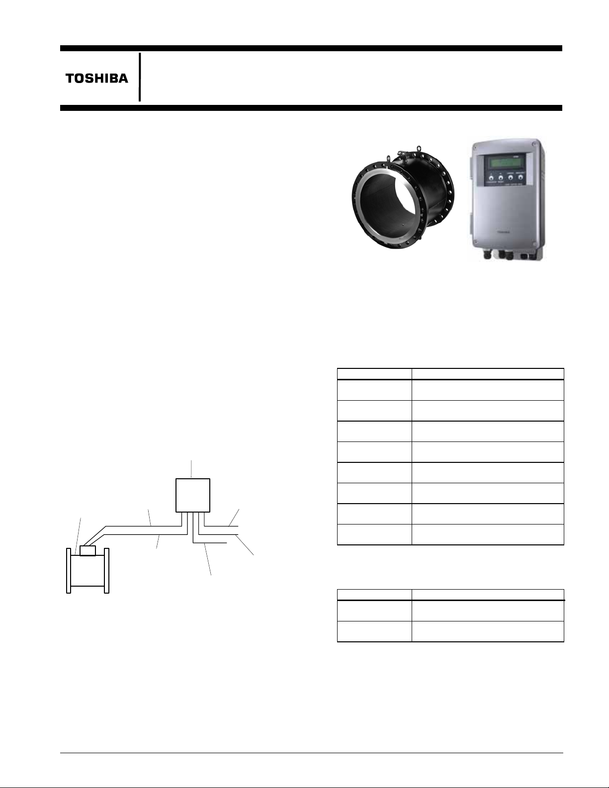
The LF502 electromagnetic flowmeter uses Faraday’s
Law of electromagnetic induction in the same way as
conventional electromagnetic flowmeters to measure
the flow rate. Position of electrodes in the LF502 is so
designed that it can be used even in a partially-filled
pipe to measure the flow rate.
Improved functional magnetic field distribution
technique enables a high-precision flow measurement
continually from low-level to fully-filled flow
conditions. This
such as lifting the downstream pipe section to fill the
detector pipe.
Compared with flowmeters measuring the flow rate by
means of flow level, the obstruction less LF502
flowmeter does not usually allow mud, sands and other
solid sediment stay at the bottom of the detector pipe
is unaffected by wave or floating solids on the fluid
and
surface.
The AF900 hand-held terminal (HART*
communicator) can be used to communicate with the
flowmeter from a remote place.
*1: HART protocol (Highway Addressable Remote
Transducer) is a communication protocol for industrial
sensors recommended by the HCF
Communication Foundation).
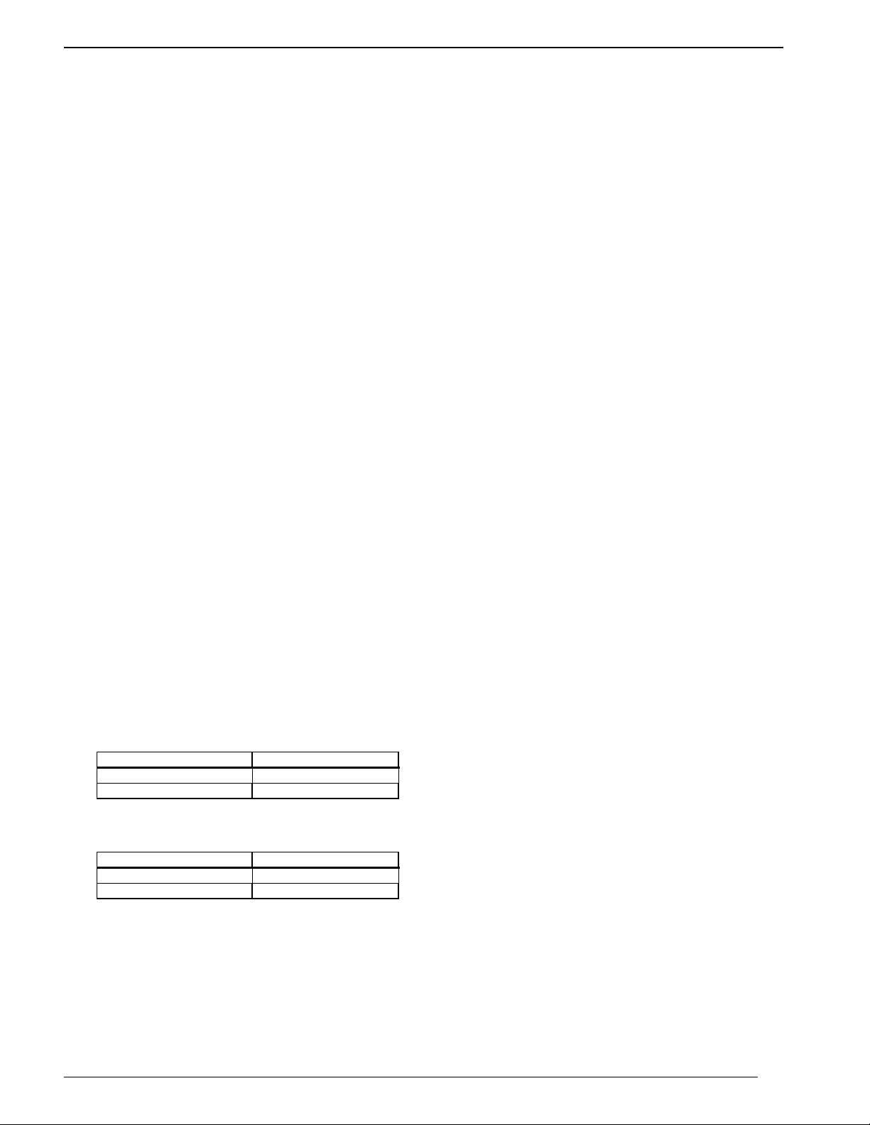
Signal cable
Detector
Excitation cable
Partially-filled Pipes
eliminates unnecessary piping work
1
(HART
Converter
Power supply
4-20 mAdc
LF502/LF232*F
6” to 24”
(150 to 600 mm )
LF502
Figure 2. LF502 Electromagnetic Flowmeter
for Partially-filled Pipes
LF232*F
Specifications
■
Overall Specifications
Measurement range:
Meter size Measurement range
6” (150mm)
8” (200mm )
10” (250mm )
12” (300mm )
14” (350mm )
16” (400mm )
20” (500mm )
24” (600mm )
Note: Above flow rate is almost 0 – 3.28 ft/s (std) to 0 –
16.4 ft/s (0 – 1 m/s to 0 – 5 m/s ) flow velocity.
0 – 264 GPM(std) to 0 – 1320 GPM
(0 – 60 m3/h to 0 – 300 m3/h )
0 – 484 GPM(std) to 0 – 2420 GPM
(0 – 110 m
0 – 770 GPM(std) to 0 – 3850 GPM
(0 – 175 m
0 – 1100 GPM(std) to 0 – 5500 GPM
(0 – 250 m3/h to 0 – 1250 m3/h )
0 – 1540 GPM(std) to 0 – 7700 GPM
(0 – 350 m3/h to 0 – 1750 m3/h )
0 – 1980 GPM(std) to 0 – 9900 GPM
(0 – 450 m
0 – 3124 GPM(std) to 0 – 15620 GPM
(0 – 710 m3/h to 0 – 3550 m3/h )
0 – 4400 GPM(std) to 0 – 22000 GPM
(0 – 1000 m
3
/h to 0 – 550 m3/h )
3
/h to 0 – 875 m3/h )
3
/h to 0 – 2250 m3/h )
3
/h to 0 – 5000 m3/h )
Digital I/O
Figure 1. LF502/LF232*F Configuration
Fluid-level range:
Meter size Specification
6” to 12” m
(150 to 300m )
14” to 24”
(350 to 600mm )
Note: The fully-filled condition means a 100% of inside
tube diameter.
1-1/4”(30mm ) to fully-filled condition.
10% of inside tube diameter to
fully-filled condition.
Accuracy: ±2% FS (when measurement range is
standard)
Note: The accuracy is measured under standard
operating
facility.
conditions at Toshiba's calibration
TIC-LF502A
Page 2
TIC-LF502A
Required straight pipe length:
10D minimum on upstream side and
5D minimum on downstream side
Note: D is a nominal meter size.
Fluid conductivity: 100µS/cm minimum
Fluid temperature: 32 to 131 °F (0 to 55 °C )
Ambient temperature: 14 to 122 °F (-10 to 50 °C )
Dimensions and Weights: See figures 3 to 5.
Power supply:
100 to 120 Vac (80 to 132 Vac), 50/60Hz
Power consumption: 50VA (30W) or less
■
Model LF502 Detector
Meter sizes: 6” (150 mm ), 8” (200 mm ), 10” (250
mm ), 12” (300 mm ), 14” (350 mm ), 16” (400
mm ), 20” (500 mm ), 24”(600 mm )
Fluid pressure:
0 psi or 0 bar (0 MPa) to the pressure limited by
flange standard
(fully-filled condition)
Connection flange standards:
ANSI 150, JIS 10K
Structure:
IP67 and NEMA 4X Watertight (std. )
IP68 and NEMA 6P Submersible (opt.)
Coating: Phthalic acid resin coating, pearl-gray
colored (standard for watertight type) or black tar
epoxy (option for watertight type and specified
exclusively for submersible type)
Principal materials:
Case — carbon steel
Measuring pipe — 304 stainless steel
Linings — The following are the standards:
Meter size Standard specification
6” to 16” (150 to 400mm ) EPDM rubber
20” & 24” (500 & 600mm ) Chloroprene rubber
Electrodes — 316L stainless steel (std.)
Grounding rings — The following are the
standards.
Meter size Standard specification
6” to 16” (150 to 400mm ) 316 stainless steel
20” & 24” (500 & 600mm ) 304 stainless steel
See Table 1 for optional materials and other
related information.
Coating: phthalic acid resin coating (std.),
Pearl-gray colored
Cable connection port:
Cable glands: Provided as standard, R(PT) 1/2
male screw.
Applicable diameter: 0.433 to 0.512 inch (11
to 13mm )
2
■
Model LF232*F converter
Input signals
Analog signal — the voltage signal from detector,
proportional to process flow rate.
Digital input DI (opt.)
(added when 9
th
digit of specification code is ”3”)
Voltage level: High level 20 to 30 V dc
Low level 2 V dc or less
Input resistance: 2.7 kΩ
Number of inputs: 2 points (DI1 and DI2)
DI functions:
For digital input function, either of the following
functions can be selected.
• Range switching
One Digital Input is used: switching between large
and small ranges of forward/reverse, 2-range
measurement.
Two Digital Inputs are used: switching between
ranges of single direction, 4-range measurement.
• Totalizer control input
Totalizer Start/Stop control or Reset/Start
•Output hold input
Fixed with set value for current output and pulse
output (loop check)
• Zero adjustment
Starts zero adjustment (on-stream at zero flow rate)
when DI voltage level goes low after remaining
high for 10 to 20 seconds.
Output signals
Current output:
4–20mAdc (load resistance 0 to 1KΩ)
Digital output (DO) — One point (std.) and three
more point is optionally available as follows.
Digital output DO1 (std.):
Output type: Transistor open collector
Number of outputs: One point
Output capacity : 30Vdc, 200mA maximum
Digital output DO2~DO4 (opt.)
(Added when 9
th
digit of specification code is “3”)
Out put type: Solidstate relay output (non polarity)
Number of outputs: 3 points
Output capacity: 150Vdc, 150mA maximum or
150Vac (peak to peak),
100mA maximum
DO functions—Four digital output function, either of
the following functions can be selected.
• Totalizer pulse output
DO1 or DO2 can be selected (Forward direction
pulse and reverse direction pulse can be assigned
Page 3

TIC-LF502A
independently)
In the case of DO1
Pulse rate: 3.6 to 3,600,000 pulses/h
Pulse width:Settable within the range of 0.3 to
500ms
In the case of DO2
Pulse rate: 3.6 to 360,000 pulses/h
Pulse width: Settable within the range of 4 to
500ms
• Rage switching output
One Digital Output (DO) is used
・Single direction, 2-range switching signal
・Forward/reverse direction switching signal
Two Digital Outputs (DO) are used
・Single direction, 4-range switching signals
・Forward/reverse 2-range switching signals
• High/low limit alarm output
An alarm is output when flow rate goes above or
below the set-point value
Setting range : -10 to 110% of the settable
maximum range
High limit 2 points, low limit 2 points can be set
At the time of alarm output, Normally Open or
Normally Closed contact can be selected
• Preset point output
Contact ON when totalizer count exceeds the set
value
Setting range: 1 to 99999999 count
• Converter error alarm
An alarm is output when an operation error is
detected by self-diagnosis.
At the time of alarm output, Normally Open or
Normally Closed contact can be selected
Communications signal:
A digital communications (HART protocol) signal is
superimposed on 4 to 20 mA dc analog output signal.
Load resistance: 240 Ω to 1 kΩ
Load capacitance: 0.25 µF or less
Load inductance: 4mH or less
(For maximum cable length, about 2km is a
guideline length when CVV-S 1.25mm
2
is used
under standard installation condition.)
Note: HART (Highway Addressable Remote
Trans-ducer) is a communications protocol for
industrial sensors recommended by the HCF
(HART Commu-nication Foundation).
Output display:
16-character×2-line dot-matrix LCD
(With back light).
2 units can be selected from the flowing units: flow
velocity, instantaneous flow rate, total flow
(forward/reverse/difference flow), total count, %,
custom unit.
Parameter settings—Parameters can be set asfollows
•IR Switches: Various parameters can be set without
opening the converter housing using 4 infrared
switches (password can be set)
•Zero adjustment: Zero point adjustment can be
started by pressing the switch in the converter.
•Digital communication: The AF 900 hand-held
terminal is needed to set parameters.
•Damping: 0.5 to 60 s
(Selectable in one second increments)
“Field re-verification”
Mag-Prover – Toshiba’s
Zero span calibration tool allows unit to be
re-calibrated and verified using an internal
software program. (For more information contact
Toshiba International Corp.)
Conditions when power fails:
Parameter setting values are stored in non-volatile
memory and the values will be restored when the
power returns to normal condition The output and
display will stay as follows when power fails..
Current output: 0 mA
Digital output : OFF (contact open)
LCD display : No display
Surge protection: Surge protectors are installed in the
power supply, excitation circuit, current signal
output and digital I/O circuit.
Terminal block structure:21-pole, screw connection
type (M4 screw)
Housing: Aluminum alloy
Coating: Acrylic resin-baked coating, pearl-gray
colored
Cable connection ports :
A cable gland is provided for each port.
OD of cable φ11 to 13 mm
Material Nylon 66
G(PF) 1/2 male screws.
Structure: IP67 and NEMA 4X Watertight
Vibration resistance:
No resonance to the following levels of vibration:
• 10 to 55Hz with amplitude of 0.07mm,
• Vibration of 30Hz with 29.4 m/s
2
in 4h in each
direction will not cause any defect to unit.
Note:
Avoid using the flowmeter in an environment
with constant vibration.
Dimension and Weights:
See Figure 5
3
Page 4

TIC-LF502A
Installation
■
Dimensions
Separate type LF502 (Meter size 6” and 8”)
3.46 (88)
1.57 (40)
1.42 (36)
Unit: inch (mm)
4.96 (126)
5.63 (143)
Figure 3. Detector Dimensions for Meter Sizes
6” (150 mm) and 8” (200 mm )
See the following tables for dimensions of L1, L2
and L3 in Figure 3 above, and the number of bolts
required for each flange.
ANSI 150 flange dimensions:
Meter
Size (inch)
6 10.47 9.67 15.14 8 Approx.84
8 11.81 10.69 17.42 8 Approx. 194
L1
(inch)
L2
(inch)
L3
(inch)
No. of
bolts
Weight
(lb)
JIS 10K flange dimensions:
Meter
Size (mm)
150 266 246 386 8 Approx. 35
200 300 271 436 12 Approx. 80
L1
(mm)
L2
(mm)
L3
(mm)
No. of
bolts
Weight
(kg)
■
Dimensions
Separate type LF502 (Meter size 10” to 24”)
3.46 (88)
1.57 (40)
11.81(300)
1.42 (36)
Unit: inch (mm)
4.96 (126)
5.63 (143)
Roll-prevention base
Figure 4. Detector Dimensions for Meter Sizes
10” (250 mm) to 24” (600 mm)
See the following tables for dimensions of L1, L2
and L3 in Figure 4 above, and the number of bolts
required for each flange.
ANSI 150 flange dimensions:
Meter
Size (inch)
10 13.78 12.05 20.05 12 263
12 15.75 12.95 22.45 12 318
14 17.72 13.74 24.24 12 359
16 19.69 15.12 26.87 16 476
20 23.62 16.42 30.17 20 527
24 23.62 18.46 34.46 20 701
L1
(inch)
L2
(inch)
L3
(inch)
No. of
bolts
Weight
(lb)
JIS 10K flange dimensions:
Meter
Size (mm)
250 350 306 506 12 Approx. 110
300 400 329 551 16 Approx. 120
350 450 351 596 16 Approx. 130
400 500 386 666 16 Approx. 180
500 600 403 740 20 Approx. 190
600 600 455 852 24 Approx. 250
L1
(mm)
L2
(mm)
L3
(mm)
No. of
Bolts
Weight
(kg)
4
Page 5

■
Dimensions
Signal cable ground
Grounding terminal
Excitation cable ground
9.33 (237)
8.74 (222)
2.91 (74)
2.99 (76)
2.99 (76)
2.99 (76)
4-φ12 hole
Output cable ground
1.57
(40)
2.17(55)
I/O cable ground
Weight : Approximately18 lb (8 kg)
6.10 (155)
15.75 (400)
Power supply cable ground
(including a mounting bracket)
TIC-LF502A
Installation method
据付方法
据付けは、パネル(壁面)取付けか
パイプ取付けで行います。
指定された取付用ボルト・ナットが付
属します。
In the case of 2B pipe installation
2Bパイプ取付けの場合
M10 U ボルト
M10 U bolts
14.57(370)
2B(50mm)パイプ
パネル取付穴加工寸法
2.91 (74)
74
11 to 12 φhole
11~12φ 穴
(4ヵ所)
4 places
370
14.57 (370)
400
15.75 (400)
Figure 5. Separate type converter LF232
*
F
5
Page 6

TIC-LF502A
(
r
■
External Connections
Grounded with 100Ω o
less ground resistance
Thick walled steel conduit
Signal cable
(2-wire shielded hard-rubber sheathed cable)
Terminal box
Ⅳ wire
2
or more
5.5mm
(3-wire hard-rubber sheathed cable)
Detector
Power supply
CVV)
Power supply
Current output (4 to 20mA)
Digital input 2 (opt.)
Digital input 1 (opt.)
(20 to 30 Vdc)
Digital output 4 (opt.)
Digital output 3 (opt.)
Digital output 2 (opt.)
Digital output
Excitation cable
Output cable
(CVV-S)
Digital I/O cable
(CVV-S)
■
Wiring Precautions
Figure 6. LF502/LF232*F flowmeter Wiring Diagram
(1) Be sure to use thick walled steel conduit (22
mm) for signal and excitation cable wiring
between the detector and converter. The
conduit screw is R (PT)1/2. Use flexible
conduits at the cable outlets of the detector as
needed.
(2) Make the grounding wire as short as possible.
Do not use a common ground shared with
other equipment where earth current may flow.
An independent earth ground is recommended.
(3) The meter may affect its accuracy when the
electric potential of measurement fluid is
unstable condition.
• Make the piping of the upstream side and
downstream side the same material.
• When the material of next pipes are conductive
like metal, use a 5.5mm
2
or larger core cable for
grounding of detector and wire it at 2 places as
follows.
• Between Grounding terminal at detector body
and Grounding ring at upstream side.
• Between Grounding terminal at detector body
and Grounding ring at downstream side.
• When the material of next pipes are
2
non-conductive like plastic, use a 5.5mm
or
larger core cable for grounding of detector and
wire 1 place as follows.
• Between Grounding terminal at detector
body and Grounding (100 ohm or less).
(4) DO1 to DO4 and DI1 to DI2 use the same
common terminal (COM). This COM can not
connect to other instruments that have their
own ground terminal (Power supply for
connecting to DI or DO, etc...). Need to wire
separately.
6
Page 7

■
n
e
o
Piping Precautions
(1) Flange connection
The flowmeter has upstream and downstream
flanges on the ends of detector pipe. Connect
these flanges with the flanges on both sides of
pipeline bore using connection bolts after
inserting a gasket between them. See Figure 7.
Tighten the bolts in even increments diagonally
across.
Observation
window
Upstream flange
Downstream flang
Bolt
Observatio
window
Gasket
Flow
directi
Figure 7. Flange Connection
(2) Required straight pipe length
The straight pipe length is required to prevent
uneven flow velocity and a disturbance on the
fluid surface in the detector pipe. The required
straight pipe length should be as follows:
• Downstream side:L = 5D minimum
• Upstream side:L = 10D minimum
where,
L = straight pipe length (straight pipeline length
+ half length of detector pipe length)
Flow regulation
valve etc.
Observation window
Detector
10D minimum
5D minimum
Note: The length of reducers, if used, can be counted as
a part of straight pipe length.
Figure 8. Required Straight Pipe Length on
Upstream and Downstream Sides
TIC-LF502A
■
About establishment environment
Do not store or install the flowmeter:
• Where there is direct sunlight.
• Where excessive vibration or mechanical shock
occurs.
• Where high temperature or high humidity
conditions exist.
• Where corrosive atmospheres exist.
• Places that can be submerged under water.
• Where there is sloped floor. To put the flowmeter
temporarily on the floor, place it carefully with
something, such as stopper, to support it so that the
flowmeter will not topple over.
In areas like the following, there may be the case that
infrared switches do not function correctly. (If these
are unavoidable, use an appropriate cover.)
(1) Where unit (operation panel) is exposed to direct
sunlight, reflection of light onto window pane and
diffused light reflection.
(2) Where smoke and steam may occur.
(3) Where exposed to direct snow, ice or mud.
■
Ordering Information
1. When ordering the LF502 flowmeter, refer to
Table 1 (Type Specification Codes). An entry
must be made for each of the columns in each of
these tables.
2. Fluid characteristics:
(1) Type of fluid to be measured and its
characteristics
(2) Fluid temperature
(3) Fluid pressure
(4) Electrical conductivity of the fluid
3. Measuring range
4. Digital I/O specifications
5. Ordering scope:
Actual flow calibration data:(Required or not)
6. Other items
Specifications other than standard items
7
Page 8

TIC-LF502A
/
Table 1. Specification Code for LF502 detector
Model Specification Code
1 2 3 4 5 6 7 8 9 10 11 12
L F 5 0 2 LF502 Electromagnetic flowmeter
Meter size
K 6" (150mm )
L 8" (200mm )
M 10" (250mm )
N 12" (300mm )
P 14" (350mm )
Q
A Standard
Connection flange standard
C ANSI 150
J JIS 10K
Lining
C Chloroprene rubber
D EPDM rubber
T Teflon PFA
Electrode and Grounding Ring Material
B 316L stainless steel + 316 stainless steel
C Titanium + Titanium
F Hastelloy C + Hastelloy C
H 316L stainless steel + 304 stainless steel
C Black tar epoxy resin , thickness 0.3mm
D Black tar epoxy resin , thickness 0.5mm
R
S
16" (400mm )
20" (500mm )
24" (600mm )
Flow and calibration velocity range
A Standard range calibration
Coating
B Phthalic acid resin
E Black tar epoxy resin , thickness 0.5mm (for submersible type)
Description
Size
A B
-
-
-
-
-
-
-
-
-
-
Code explanation: : Standard : Option –: Not available
Size groups
A : 6” (150mm ) to 16” (400mm )
B : 20” (500mm ) and 24” (600mm )
Model Specification Code
1 2 3 4 5 6 7 8 9 10 11 12
L F 2 3 2
F
1
1
A
A
C
E
Code explanation: : Standard : Option
ISO9001 and ISO14001 certified.
Misuse of this product can result in damages to property or human injury.
Read related manuals carefully before using this product.
Table 2. Specification Code for LF232*F converter
Contents
Separate type converter
1
3
Purpose
Compatible detectors
Mounting nuts and bolts
Digital input/output
Current output
Current output
Communication function
HART communication
Power supply
Standard
Standard
For Partially-filled pipes (Meter size : 150mm(6”) to 600mm(24”) )
Panel, wall mounting (material : 304 stainless steel)
Pipe mounting (material : 304 stainless steel)
+ Digital output points (1 point)
+ Digital output points (4 points) + Digital input points (2 points)
100Vac-120Vac, 50/60Hz
Specifications are subject to change without notice.
LF232
type
Printed in Japan 2008-5 (TDOC)
© TOSHIBA Corporation 2008
All Rights Reserved.
http://www.toshiba.com/ind
TIC-LF502A
 Loading...