

Page 1

User’s Manual
TOSHIBA Satellite L350/Satellite Pro L350/ Satellite L350D/ Satellite Pro L350D series
computers.toshiba-europe.com
Page 2

Copyright
Disclaimer
Satellite L350/Satellite Pro L350/Satellite L350D/Satellite Pro L350D series
© 2009 by TOSHIBA Corporation. All rights reserved. Under the copyright
laws, this manual cannot be reproduced in any form without the prior
written permission of TOSHIBA. No patent liability is assumed, with respect
to the use of the information contained herein.
TOSHIBA Satellite L350/Satellite Pro L350/Satellite L350D/
Satellite Pro L350D series Portable Personal Computer User’s Manual
First edition October 2009
Copyright authority for music, movies, computer programs, data bases and
other intellectual property covered by copyright laws belongs to the author
or to the copyright owner. Copyrighted material can be reproduced only for
personal use or use within the home. Any other use beyond that stipulated
above (including conversion to digital format, alteration, transfer of copied
material and distribution on a network) without the permission of the
copyright owner is a violation of copyright or author’s rights and is subject
to civil damages or criminal action. Please comply with copyright laws in
making any reproduction from this manual.
This manual has been validated and reviewed for accuracy. The
instructions and descriptions it contains are accurate for the TOSHIBA
Satellite L350/Satellite Pro L350/Satellite L350D/
Satellite Pro L350D series Portable Personal Computer at the time of this
manual’s production. However, succeeding computers and manuals are
subject to change without notice. TOSHIBA assumes no liability for
damages incurred directly or indirectly from errors, omissions or
discrepancies between the computer and the manual.
Trademarks
IBM is a registered trademark, and IBM PC and PS/2 are trademarks of
International Business Machines Corporation.
Intel, Intel SpeedStep and Intel Core and Centrino are trademarks or
registered trademarks of Intel Corporation or its subsidiaries in the United
States and other countries/regions.
AMD, the AMD Arrow logo, AMD Athlon, AMD Turion, Radeon, and
combinations thereof, ATI Mobility Radeon™ are trademarks of Advanced
Micro Devices, Inc.
Windows and Microsoft are registered trademarks of Microsoft Corporation.
Photo CD is a trademark of Eastman Kodak.
Memory Stick is a registered trademark of SonyCorporation.
User’s Manual i
Page 3

Satellite L350/Satellite Pro L350/Satellite L350D/Satellite Pro L350D series
Manufactured under license from Digital Theater Systems, Inc. U.S. Pat.
No's. 5,451,942; 5,956,674; 5,974,380; 5,978,762; 6,226,616; 6,487,535
and other U.S. and world-wide patents issued and pending. "DTS" and
"DTS Digital Surround" are registered trademarks of Digital Theater
Systems, Inc. Copyright 1996, 2003 Digital Theater Systems, Inc. All Rights
Reserved.
Other trademarks and registered trademarks not listed above may be used
in this manual.
Macrovision License of Notice
For RTLA(Restricted Technology License Agreement)
This product incorporates copyright protection technology that is protected
by U.S. patents and foreign patents, including patent numbers 5,315,448;
5,583,936; 6,636,549; 7,050,698, and other intellectual property rights.
The use of Macrovision's copy protection technology in the product must
be authorized by Macrovision. Reverse engineering or disassembly is
prohibited. The copyright protection technology availability depends on
the model you purchased.
Safety instructions
Use the following safety guidelines to help to protect yourself and your
computer.
When using your computer
Do not operate your portable computer for an extended period of time with
the base resting directly on your body. With extended operation, heat can
potentially build up in the base. Allowing sustained contact with the skin
could cause discomfort or, eventually, a burn.
■ Do not attempt to service the computer yourself. Always follow
installation instructions closely.
■ Do not carry a battery in your pocket, purse, or other container where
metal objects (such as car keys) could short-circuit the battery
terminals. The resulting excessive current follow can cause extremely
high temperatures and may result in damage from burns.
■ Be sure that nothing rests on your AC adapter’s power cable and that
the cable is not located where it can be tripped over or stepped on.
■ Place the AC adapter in a ventilated area, such as a desk top or on the
floor, when you use it to run the computer or to charge the battery. Do
not cover the AC adapter with papers or other items that will reduce
cooling; also, do not use the AC adapter while it is inside a carrying
case.
User’s Manual ii
Page 4

Satellite L350/Satellite Pro L350/Satellite L350D/Satellite Pro L350D series
■ Use only the AC adapter and batteries that are approved for use with
this computer. Use of another type of battery or AC adapter may risk fire
or explosion.
■ Before you connect the computer to a power source, ensure that the
voltage rating of the AC adapter matches that of the available power
source. 115 V/60 Hz in most of North and South America an d some Far
Eastern countries and regions such as Taiwan. 100 V/50 Hz in eastern
Japan and 100 V/60 Hz in western Japan. 230 V/50 Hz in most of
Europe, the Middle East, and the Far East.
■ If you use an extension cable with your AC adapter , ensu re that the total
ampere rating of the products plugged in to the extension cable does
not exceed the ampere rating of the extension cable.
■ To remo ve po wer from th e com pu ter, turn it off, remov e the ba tte ry, and
disconnect the AC adapter from the electrical outlet.
■ To help avoid the potential hazard of electric shock, do not connect or
disconnect any cable s or perform main tenance or recon figuration of this
product during an electrical stor m.
■ When setting up the computer for work, place it on a level surface.
EU Conformity Statement
This product and - if applicable - the supplied accessories too are marked
with "CE" and comply therefore with the applicable harmonized European
standards listed under the Low Voltage Directive 2006/95/EC, the EMC
Directive 2004/108/EC and/or R&TTE Directive 1999/5/EC.
Responsible for CE-marking is TOSHIBA EUROPE GmbH,
Hammfelddamm 8, D-41460 Neuss, Germany.
Manufacturer is TOSHIBA Corporation, 1-1 Shibaura 1-chome, Minato-ku,
Tokyo, 105-8001, Japan.
The complete official EU CE Declaration can be obtained on following
internet page: http://epps.toshiba-teg.com
CE compliance
This product is labelled with the CE Mark in accordance with the related
European Directives, notably Electromagnetic Compatibility D ire cti ve 2004 /
108/EC for the notebook and the electronic accessories including the
supplied power adapter, the Radio Equipment and Telecommunications
Terminal Equipment Directive 1999/5/EC in case of implemented
telecommunication ac ce ss ories and the Low Voltage Directive 2006/95/EC
for the supplied power adapter.
User’s Manual iii
Page 5

Satellite L350/Satellite Pro L350/Satellite L350D/Satellite Pro L350D series
This product and the original options are designed to observe the related
EMC (Electromagnetic Compatibility) and safety standards. However,
TOSHIBA cannot guarantee that this product still observes these EMC
standards if options or cables not produced by TOSHIBA are connected or
implemented. In this case the persons who have connected / implemented
those options / cables have to provide assurance that the system (PC plus
options / cables) still fulfils the required standards. To avoid general EMC
problems, the following gui dance should be noted:
■ Only CE marked options should be connected / implemented
■ Only best shielded cables should be connected
Working environment
This product was des igned to fulfil th e EMC (Electromag netic Comp atibility)
requirements to be observed for so-called "Residential, commercial and
light industry environments".
TOSHIBA do not approve the use of this product in working environments
other than the above m entioned "Residenti al, commerc ial and lig ht industry
environments".
For example, the following environments are not approved:
■ Industrial Environments (e.g. environments where a mains voltage of
380 V three-phase is used)
■ Medical Environments
■ Automotive Environments
■ Aircraft Environments
Any consequences resulting from the use of this product in working
environments that ar e no t app rov ed are not the res po ns ibi lit y of TOSHIBA.
The consequences of the use of this product in non-approved working
environments may be:
■ Interference with other devices or machines in the near surroundi ng
area.
■ Malfunction of, or data loss from, this product caused by disturbances
generated by other devices or machines in the near surrounding area.
Therefore TOSHIBA strongly recommend that the electromagnetic
compatibility of this product should be suitably tested in all non-approved
working environmen ts befor e use. In the ca se of au tomob iles o r aircraft, the
manufacturer or airline respectively should be asked for permission before
use of this product.
Furthermore, for general safety reasons, the use of this product in
environmen ts with explosive atmospheres is not per m itted.
User’s Manual iv
Page 6

Satellite L350/Satellite Pro L350/Satellite L350D/Satellite Pro L350D series
Modem warning notice
Conformity statement
The equipment has been approved to [Commission Decision "CTR21"] for
pan-European sin gle terminal c onnectio n to the Publi c Switched Telephone
Network (PSTN).
However, due to differences between the individual PSTNs provided in
different countries/regions the approval does not, of itself, give an
unconditional assurance of successful operation on every PSTN network
termination point.
In the event of problems , you shoul d conta ct your equi pment suppli er in the
first instance.
Network compatibility statement
This product is designed to work with, and is compatible with the following
networks. It has been tested to and found to conform with the additional
requirements conditional in EG 201 121.
Germany ATAAB AN005,AN006,AN007,AN009,AN01 0
Greece ATAAB AN005,AN006 and GR01,02,03,04
Portugal ATAAB AN001,005,006,007,011 and
Spain ATAAB AN005,007,012, and ES01
Switzerland ATAAB AN002
All other countries/
regions
Specific switch settings or software setup is required for each network,
please refer to the relevant sections of the user guide for more details.
The hookflash (timed break register recall) function is subject to separate
national type approvals. It has not been tested for conformity to national
type regulations, and no guarantee of successful operation of that specific
function on specific national networks can be given.
and DE03,04,05,08,09,12,14,17
P03,04,08,10
ATAAB AN003,004
User’s Manual v
Page 7
Satellite L350/Satellite Pro L350/Satellite L350D/Satellite Pro L350D series
Following Information Is Only Valid for EU-member States
Disposal of Products
The crossed out wheeled dust bin symbol indicates that products must be
collected and disposed of separately from household waste. Integrated
batteries and accumulators can be disposed of with the product. They will
be separated at the recycling centres.
The black bar indicates that the product was placed on the market after
August 13, 2005.
By participating in separate collection of products and batteries, you will
help to assure the proper disposal of products and batteries and thus help
to prevent potential negati ve co nse qu enc es for the enviro nm ent and
human health.
For more detailed information about the collection and recycling
programmes available in your country, please visit our websit e
(http://eu.computers.toshiba-europe.com) or contact your local city
office or the shop where you purchased the produc t.
Disposal of Batteries and/or Accumulators
The crossed out wheeled dust bin symbol indicates that batteries and/or
accumulators must be collected and disposed of separately from
household waste.
If the battery or accumulator contains more than the specified values of
Pb, Hg,Cd
lead (Pb), mercury (Hg), and/or cadmium (Cd) defined in the Battery
Directive (2006/66/EC), then the chemical symbols for lead (Pb), mercury
(Hg) and/or cadmium (Cd) will appear below the crossed out wheeled dust
bin symbol .
By participating in separate collection of batteries, you will help to assure
the proper disposal of products and batteries and thus help to prevent
potential negative conse quences for the environment and human health.
For more detailed information about the collection and recycling
programmes available in your country, please visit our websit e
(http://eu.computers.toshiba-europe.com) or contact your local city
office or the shop where you purchased the produc t.
This symbol may not be displayed depending on the country and region
where you purchased.
User’s Manual vi
Page 8

ENERGY STAR
Y our computer mo del may be ENERGY STAR
purchased is compliant, it is labeled with the ENERGY STAR
computer and the following information applies.
TOSHIBA is a partner in the En vironmental Protection Agency's (E PA)
ENERGY STAR
latest ENERGY STAR® guidelines for energy efficiency. Your computer
ships with the power man agement o ptions p reset to a configura tion that w ill
provide the most stable operating environment and optimum system
performance for both AC power and battery modes.
To conserve energy, your computer is set to enter the low-power Sleep
mode which shuts down the system and display within 15 minutes of
inactivity in AC power mode. We recomm end that you leave this and other
energy saving features active, so that your computer will operate at its
maximum energy efficiency. You can wake the computer from Sleep mode
by pressing the power button.
According to the EPA, a computer meeting the new ENERGY STAR
specifications will use between 20 % and 50 % less energy depending on
how it is used. If all U.S. household and businesses replaced old
computers with new ENERGY STAR
more than $1.8 billion in energy costs over the next five years and avoid
greenhouse gas emissions equivalent to more than 2.7 million cars.
If every computer purchased by businesses next year met the new
ENERGY STAR
$210 million over the li feti me of thos e mo dels. That is equivalent to lighti ng
120 million square feet of U.S. commercial building space each year.
Visit http://www.energystar.gov or
http://www.energystar.gov/powermanagement
for more information regarding the ENERGY STAR
Satellite L350/Satellite Pro L350/Satellite L350D/Satellite Pro L350D series
®
Program
®
Compliant. If the model you
®
Program and has designed this computer to meet the
®
qualified models, we would save
®
requirements, businesses would save more than
®
Program.
®
logo on the
®
REACH - Compliance Statement
The new European Union (EU) chemical regulation, REACH (Registration,
Evaluation, Authorization and Restriction of Chemicals), entered into force
on 1 June 2007. Toshiba will meet all REACH requirements and is
committed to provide our customers with information about the chemical
substances in our prod ucts ac cording to REAC H regulation. Ple ase consult
the following website http://www.toshiba-europe.com/computers/info/reach
for information abou t the presen ce in our articl es of subs tance s include d on
the candidate list according to article 59(1) of Regulation (EC) No 1907/
2006 ("REACH") in a concentration above 0.1 % weight by weight.
User’s Manual vii
Page 9
Satellite L350/Satellite Pro L350/Satellite L350D/Satellite Pro L350D series
Following information is only for Turkey:
■ Compliant with EEE Regulations: Toshiba meets all requirements of
Turkish regulation 26891 "Restriction of the use of certain hazardous
substances in electrical and electronic equipment".
■ The number of possible pixel failures of your display is defined
according to ISO 13406-2 standards. If the number of pixel failures is
less than this standard, they will not be counted as defect or failure.
■ Battery is a consumption product , since the batte ry time depends on the
usage of your computer. If the battery can not be charged at all, then it
is a defect or failure. The changes in battery time is not a defect or
failure.
GOST
Optical disc drive standards
TOSHIBA SatelliteL350/Satellite Pro L350/Satellite L350D/
Satellite Pro L350D series computer is shipped with one of the following
drives preinstalled: CD-RW/DVD-ROM, DVD Super Multi (±R DL).
The drive has one of the following labels:
CLASS 1 LASER PRODUCT
LASER KLASSE 1
LUOKAN 1 LASERLAITE
APPAREIL A LASER DE CLASSE1
KLASS 1 LASER APPARAT
Before it is shipped, the Clas s 1 Lase r is certifi ed to mee t the United States
Chapter 21 Standards of the Department of Health and Human Services
(DHHS 21 CFR).
For any other country, the drive is certified to meet the Class 1 Laser
standards of IEC825 and EN60825 .
User’s Manual viii
Page 10
Satellite L350/Satellite Pro L350/Satellite L350D/Satellite Pro L350D series
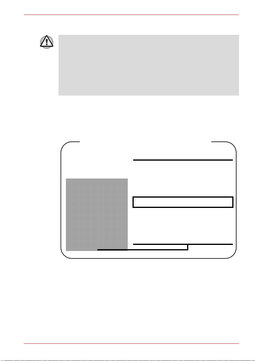
Location of the required label
PRODUCT IS CERTIFIED BY THE
MANUFACTURER TO COMPLY WITH
DHHS RULES 21 CFR SUBCHAPTER
J APPLICABLE AT THE DATE OF
MANUFACTURE.
MANUFACTURED
Toshiba Samsung Strage Tech nology
Korea corporation
416, Maetan-3Dong, Yeongtong-Gu
Suwon City, Gyeonggi-Do, 443-742,
Korea
Optical disc drive safety instructions
■ The drive employs a laser system. To ensure proper use of this
product, please read this instruction manual carefully and retain for
future reference.
Should the unit ever require maintenance, contact an authorized
service location.
■ Use of controls, adjustments or the performance of procedures other
than those specified may result in hazardous radiation exposure
■ To prevent direct exposure to the laser beam, do not try to open the
enclosure.
CD-RW/DVD-ROM drive
Toshiba Samsung TS-L462D/TS-L463A
User’s Manual ix
Page 11
Satellite L350/Satellite Pro L350/Satellite L350D/Satellite Pro L350D series
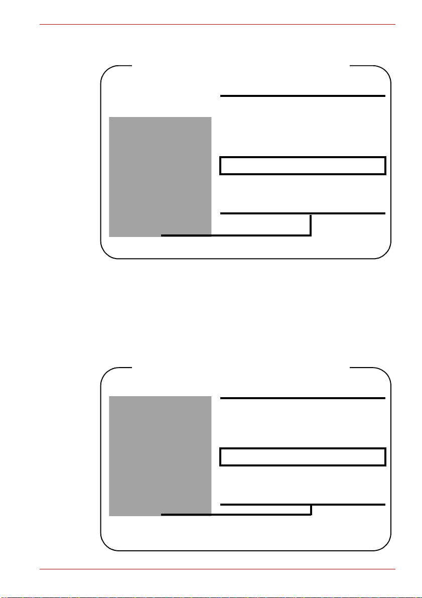
Location of the required label
PRODUCT IS CERTIFIED BY THE
MANUFACTURER TO COMPLY WITH
DHHS RULES 21 CFR SUBCHAPTER
J APPLICABLE AT THE DATE OF
MANUFACTURE.
MANUFACTURED
TEAC CORPORATION
1-47 OCHIAI, TAMA-SHI,
TOKYO, JAPAN
Location of the required label
COMPLIES WITH FDA RADIATION
PERFORMANCE STANDARDS, 21
CFR SUBCHAPTER J.
MANUFACTURED
Panasonic Communications Co., Ltd.
1-62, 4-Chome Minoshima
Hakata-ku F ukuoka, Japan
TEAC DW-224E/DW-224S
DVD Super Multi (±R DL) drive
Panasonic Com m u ni c ations
UJ870AB/UJ870EB
UJ880AD/UJ880ED
UJ890AD/UJ890ED
User’s Manual x
Page 12
Satellite L350/Satellite Pro L350/Satellite L350D/Satellite Pro L350D series
Location of the required label
PRODUCT IS CERTIFIED BY THE
MANUFACTURER TO COMPLY WITH
DHHS RULES 21 CFR CHAPTER 1,
SUBCHAPTER J, APPLICABLE AT
THE DATE OF MANUFACTURE.
MANUFACTURED
Toshiba Samsung Storage Technology
Korea Corporation
14F Digital Empire II, 486 Sin-dong,
Youngtong-gu, Suwon-si, Gyeonggi-Do,
Korea, 443-734
Location of the required label
COMPLIES WITH FDA RADIATION
PERFORMANCE STANDARDS, 21
CFR SUBCHAPTER J.
MANUFACTURED
Hitachi-LG Data Storage, Inc.
22-23, Kaigan 3-chome, Minato-Ku,
Tokyo, 108-0022 Japan
Toshiba Samsung Storage Technology
TS-L633A/TS-L633P
TS-L633C/TS-L633Y
Hitachi-LG Data Storage
GSA-T50F/GSA-T50N
GT20N/GT20F
User’s Manual xi
Page 13

Satellite L350/Satellite Pro L350/Satellite L350D/Satellite Pro L350D series
International precautions
CAUTION: This appliance contains a
laser system and is classified as a
"CLASS 1 LASER PRODUCT" To use
this model properly, read the instruction
manual carefully and kee p this m anual f or
your future reference. In case of any
trouble with this model, please contact
your nearest "AUTHORIZED service
station." To preve nt dire ct ex posur e to th e
laser beam, do not try to open the
enclosure.
VORSICHT: Dieses Gerät enthält ein
Laser-System und ist als
„LASERSCHUTZKLASSE 1 PRODUKT“
klassifiziert. Für den richtigen Gebrauch
dieses Modells lesen Sie bitte die
Bedienungsanlei tung sorgfälti g durch und
bewahren diese bitte als Referenz auf.
Falls Probleme mit diesem Modell
auftreten, benachrichtigen Sie bitte die
nächste „autorisierte Service -Vertretung“.
Um einen direkten Kontakt mit dem
Laserstrahl zu vermeiden darf das Gerät
nicht geöffnet werden.
ADVARSEL: Denne mærking er anbragt
udvendigt på apparatet og indikerer, at
apparatet arbejder med laserstråler af
klasse 1, hviket betyder, at der anvendes
laserstrlier af svageste klasse, og at man
ikke på apparatets yderside kan bilve
udsat for utilladellg kraftig stråling.
APPARATET BOR KUN ÅBNES AF
FAGFOLK MED SÆRLIGT KENDSKAB
TIL APPARATER MED
LASERSTRÅLER!
Indvendigt i apparatet er anbragt den her
gengivne advarselsmækning, som
advarer imod at foretage såda nne indgreb
i apparatet, at man kan komme til at
udsatte sig for laserstråling.
User’s Manual xii
Page 14

Satellite L350/Satellite Pro L350/Satellite L350D/Satellite Pro L350D series
OBS! Apparaten i nnehåller
laserkomponent som avger la serstr åining
överstigande gränsen för laserklass 1.
VAROITUS. Suojakoteloa si saa avata.
Laite sisältää laserdiodin, joka lähetää
näkymätöntä silmilie vaarallista
lasersäteilyä.
CAUTION: USE OF CONTROLS OR
ADJUSTMENTS OR PERFORMANCE
OF PROCEDURES OTHER THAN
THOSE SPECIFIED IN THE OWNER’S
MANUAL MAY RESUL T IN HAZARDOUS
RADIATION EXPOSURE.
VORSICHT: DIE VERWENDUNG VON
ANDEREN STEUERUNGEN ODER
EINSTELLUNGEN ODER DAS
DURCHFÜHREN VON ANDEREN
VORGÄNGEN ALS IN DER
BEDIENUNGSANLEITUNG
BESCHRIEBEN KÖNNEN
GEFÄHRLICHE
STRAHLENEXPOSITIONEN ZUR
FOLGE HABEN.
User’s Manual xiii
Page 15

Satellite L350/Satellite Pro L350/Satellite L350D/Satellite Pro L350D series
Table of Contents
Chapter1 Introduction
Equipment checklist. . . . . . . . . . . . . . . . . . . . . . . . . . . . . . . . . . . . . . . 1-1
Features. . . . . . . . . . . . . . . . . . . . . . . . . . . . . . . . . . . . . . . . . . . . . . . . . 1-3
Special features . . . . . . . . . . . . . . . . . . . . . . . . . . . . . . . . . . . . . . . . . . 1-9
TOSHIBA Value Added Package . . . . . . . . . . . . . . . . . . . . . . . . . . . . 1-10
Utilities and applications. . . . . . . . . . . . . . . . . . . . . . . . . . . . . . . . . . 1-11
Options . . . . . . . . . . . . . . . . . . . . . . . . . . . . . . . . . . . . . . . . . . . . . . . . 1-12
Chapter2 The Grand Tour
Front with the display closed . . . . . . . . . . . . . . . . . . . . . . . . . . . . . . . 2-1
Left side. . . . . . . . . . . . . . . . . . . . . . . . . . . . . . . . . . . . . . . . . . . . . . . . . 2-2
Right side . . . . . . . . . . . . . . . . . . . . . . . . . . . . . . . . . . . . . . . . . . . . . . . 2-4
Back side. . . . . . . . . . . . . . . . . . . . . . . . . . . . . . . . . . . . . . . . . . . . . . . . 2-5
Underside . . . . . . . . . . . . . . . . . . . . . . . . . . . . . . . . . . . . . . . . . . . . . . . 2-5
Front with the display open. . . . . . . . . . . . . . . . . . . . . . . . . . . . . . . . . 2-6
Function Button . . . . . . . . . . . . . . . . . . . . . . . . . . . . . . . . . . . . . . . . . . 2-8
System indicators. . . . . . . . . . . . . . . . . . . . . . . . . . . . . . . . . . . . . . . . . 2-8
Keyboard indicators. . . . . . . . . . . . . . . . . . . . . . . . . . . . . . . . . . . . . . . 2-9
Optical disc drive . . . . . . . . . . . . . . . . . . . . . . . . . . . . . . . . . . . . . . . . 2-10
AC adapter . . . . . . . . . . . . . . . . . . . . . . . . . . . . . . . . . . . . . . . . . . . . . 2-11
Chapter3 Getting Started
Connecting the AC adapter. . . . . . . . . . . . . . . . . . . . . . . . . . . . . . . . . 3-2
Opening the display. . . . . . . . . . . . . . . . . . . . . . . . . . . . . . . . . . . . . . . 3-4
Turning on the power. . . . . . . . . . . . . . . . . . . . . . . . . . . . . . . . . . . . . . 3-5
Starting up for the first time . . . . . . . . . . . . . . . . . . . . . . . . . . . . . . . . 3-5
Turning off the power. . . . . . . . . . . . . . . . . . . . . . . . . . . . . . . . . . . . . . 3-5
Restarting the computer . . . . . . . . . . . . . . . . . . . . . . . . . . . . . . . . . . . 3-8
System recovery options. . . . . . . . . . . . . . . . . . . . . . . . . . . . . . . . . . . 3-9
User’s Manual xiv
Page 16

Satellite L350/Satellite Pro L350/Satellite L350D/Satellite Pro L350D series
Chapter4
Operating Basics
Using the touchpad . . . . . . . . . . . . . . . . . . . . . . . . . . . . . . . . . . . . . . . 4-1
Using optical disc drives. . . . . . . . . . . . . . . . . . . . . . . . . . . . . . . . . . . 4-2
Writing CD/DVDs on DVD Super Multi (±R DL) drive. . . . . . . . . . . . . 4-7
TOSHIBA Disc Creator. . . . . . . . . . . . . . . . . . . . . . . . . . . . . . . . . . . . 4-10
TOSHIBA DVD PLAYER . . . . . . . . . . . . . . . . . . . . . . . . . . . . . . . . . . . 4-12
Media care. . . . . . . . . . . . . . . . . . . . . . . . . . . . . . . . . . . . . . . . . . . . . . 4-13
Using the web camera . . . . . . . . . . . . . . . . . . . . . . . . . . . . . . . . . . . . 4-13
Using the microphone . . . . . . . . . . . . . . . . . . . . . . . . . . . . . . . . . . . . 4-16
Using the TOSHIBA Face Recognition . . . . . . . . . . . . . . . . . . . . . . . 4-16
Modem. . . . . . . . . . . . . . . . . . . . . . . . . . . . . . . . . . . . . . . . . . . . . . . . . 4-19
Wireless communications . . . . . . . . . . . . . . . . . . . . . . . . . . . . . . . . . 4-22
LAN . . . . . . . . . . . . . . . . . . . . . . . . . . . . . . . . . . . . . . . . . . . . . . . . . . . 4-23
Cleaning the computer. . . . . . . . . . . . . . . . . . . . . . . . . . . . . . . . . . . . 4-24
Moving the computer. . . . . . . . . . . . . . . . . . . . . . . . . . . . . . . . . . . . . 4-25
Heat dispersal. . . . . . . . . . . . . . . . . . . . . . . . . . . . . . . . . . . . . . . . . . . 4-25
Chapter5 The Keyboard
Typewriter keys. . . . . . . . . . . . . . . . . . . . . . . . . . . . . . . . . . . . . . . . . . . 5-1
Function keys: F1 … F9. . . . . . . . . . . . . . . . . . . . . . . . . . . . . . . . . . . . 5-1
Soft keys: FN key combinations . . . . . . . . . . . . . . . . . . . . . . . . . . . . . 5-2
Windows special keys . . . . . . . . . . . . . . . . . . . . . . . . . . . . . . . . . . . . . 5-4
Generating ASCII characters. . . . . . . . . . . . . . . . . . . . . . . . . . . . . . . . 5-4
Chapter6 Power and Power-up Modes
Power conditions . . . . . . . . . . . . . . . . . . . . . . . . . . . . . . . . . . . . . . . . . 6-1
Power indicators. . . . . . . . . . . . . . . . . . . . . . . . . . . . . . . . . . . . . . . . . . 6-2
Battery types. . . . . . . . . . . . . . . . . . . . . . . . . . . . . . . . . . . . . . . . . . . . . 6-3
Care and use of the battery pack . . . . . . . . . . . . . . . . . . . . . . . . . . . . 6-5
Replacing the battery pack . . . . . . . . . . . . . . . . . . . . . . . . . . . . . . . . 6-11
Starting the computer by password . . . . . . . . . . . . . . . . . . . . . . . . . 6-13
Power-up modes. . . . . . . . . . . . . . . . . . . . . . . . . . . . . . . . . . . . . . . . . 6-14
Chapter7 HW Setup and Passwords
HW Setup. . . . . . . . . . . . . . . . . . . . . . . . . . . . . . . . . . . . . . . . . . . . . . . . 7-1
Chapter8 Optional Devices
ExpressCard . . . . . . . . . . . . . . . . . . . . . . . . . . . . . . . . . . . . . . . . . . . . . 8-1
Multiple digital media card slot . . . . . . . . . . . . . . . . . . . . . . . . . . . . . . 8-3
Memory expansion . . . . . . . . . . . . . . . . . . . . . . . . . . . . . . . . . . . . . . . . 8-5
Additional battery pack (6 Cell and 9 Cell). . . . . . . . . . . . . . . . . . . . . 8-8
Additional AC adapter . . . . . . . . . . . . . . . . . . . . . . . . . . . . . . . . . . . . . 8-8
USB FDD Kit . . . . . . . . . . . . . . . . . . . . . . . . . . . . . . . . . . . . . . . . . . . . . 8-8
External monitor. . . . . . . . . . . . . . . . . . . . . . . . . . . . . . . . . . . . . . . . . . 8-8
HDMI . . . . . . . . . . . . . . . . . . . . . . . . . . . . . . . . . . . . . . . . . . . . . . . . . . . 8-9
Security lock. . . . . . . . . . . . . . . . . . . . . . . . . . . . . . . . . . . . . . . . . . . . 8-11
User’s Manual xv
Page 17

Satellite L350/Satellite Pro L350/Satellite L350D/Satellite Pro L350D series
Chapter9
Troubleshooting
Problem solving process. . . . . . . . . . . . . . . . . . . . . . . . . . . . . . . . . . . 9-1
Hardware and system checklist . . . . . . . . . . . . . . . . . . . . . . . . . . . . . 9-3
TOSHIBA support. . . . . . . . . . . . . . . . . . . . . . . . . . . . . . . . . . . . . . . . 9-14
Chapter 10 Legal Footnotes
CPU*1. . . . . . . . . . . . . . . . . . . . . . . . . . . . . . . . . . . . . . . . . . . . . . . . . . 10-1
Memory (main system)*2. . . . . . . . . . . . . . . . . . . . . . . . . . . . . . . . . . 10-2
Battery life*3 . . . . . . . . . . . . . . . . . . . . . . . . . . . . . . . . . . . . . . . . . . . . 10-2
HDD Drive Capacity and External HDD Capacity*4 . . . . . . . . . . . . . 10-3
LCD*5. . . . . . . . . . . . . . . . . . . . . . . . . . . . . . . . . . . . . . . . . . . . . . . . . . 10-3
Graphics Processor Unit (GPU)*6. . . . . . . . . . . . . . . . . . . . . . . . . . . 10-3
Wireless LAN*7. . . . . . . . . . . . . . . . . . . . . . . . . . . . . . . . . . . . . . . . . . 10-3
Non-applicable icons . . . . . . . . . . . . . . . . . . . . . . . . . . . . . . . . . . . . . 10-4
Copy protection . . . . . . . . . . . . . . . . . . . . . . . . . . . . . . . . . . . . . . . . . 10-4
Images. . . . . . . . . . . . . . . . . . . . . . . . . . . . . . . . . . . . . . . . . . . . . . . . . 10-4
LCD brightness and eye strain . . . . . . . . . . . . . . . . . . . . . . . . . . . . . 10-4
Appendix A Specifications
Appendix B Display Controller
Appendix C Wireless LAN
Appendix D AC Power Cord and Connectors
Appendix E If your computer is stolen
Glossary
Index
User’s Manual xvi
Page 18

Preface
Congratulations on your purchase of the TOSHIBA SatelliteL350/
Satellite Pro L350/Satellite L350D/Satellite Pro L350D series computer.
This powerful, lightweight notebook computer is designed to provide years
of reliable, high-performance computing.
This manual tells you how to set up and begin using your Satellite L350/
Satellite Pro L350/Satellite L350D/Satellite Pro L350D series computer. It
also provides detailed information on configuring your computer, basic
operations and care, using optional devices and troubleshooting.
If you are a new user of computers or if you’re new to portable computing,
first read over the Introduction and The Grand Tour chapters to familiarize
yourself with the c om puter’s features, co mpo nents and accessory device s.
Then read Getting St a rted for step-by-step instructions on setting up your
computer.
If you are an experienced computer user, please continue reading the
preface to learn how this manual is organized, then become acquainted
with this manual by browsin g through it s pag es. Be sure to rea d the Special
features section of the Introduction, to learn about features that are
uncommon or unique to the computers and carefully read HW Setup and
Passwords, If you are going to install ExpressCards or connect external
devices such as a printer, be sure to read Chapter 8,Optional Devices.
Satellite L350/Satellite Pro L350/Satellite L350D/Satellite Pro L350D series
Manual contents
This manual is compose d of the following chapters, app endixes, a glos sary
and an index.
Chapter 1, Introduction, is an overview of the computer’s features,
capabilities, and options.
Chapter 2, The Grand Tour, identi fie s the co mp one nts of the computer and
briefly explains how they function.
Chapter 3, Getting Started, provides a quick overview of how to begin
operating your computer.
Chapter 4, Operating Basics, includes tips on care of the computer and on
using the touchpad, optical disc drive, external diskette drive, Wireless
LAN, LANs, Audio/Video controls, and internal modem.
Chapter 5, The Keyboard, describes special keyboard functions including
the keypad overlay and hot keys.
User’s Manual xvii
Page 19

Chapter 6, Power and Power-up Modes, gives details on the computer’s
power resources and battery save modes.
Chapter 7, HW Setup and Passwords, explains how to configure the
computer using the HW Setup program. It also tells how to set a password.
Chapter 8, Optional Devices, describes the optional hardw are ava il abl e.
Chapter 9, Troubleshooting, provides helpful inform ation on ho w to p erfor m
some diagnostic tests, and suggests courses of action if the computer
doesn’t seem to be working properly.
Chapter 10 Legal Footnotes, provides Legal Footnotes information related
to your computer.
The Appendixes provide technical information about your computer.
The Glossary defines general computer terminology and includes a list of
acronyms used in the text.
The Index quickly directs you to the information contained in this manual.
Conventions
This manual uses the following formats to describe, identify, and highlight
terms and operating procedures.
Abbreviations
On first appearance, an d whe nev er necessary for clarity , abb rev iati on s are
enclosed in parenthesis following their definition. For example: Read Only
Memory (ROM). Acronyms are also defined in the Glossary .
Satellite L350/Satellite Pro L350/Satellite L350D/Satellite Pro L350D series
Icons
Icons identify ports, dials, and other parts of your computer. The indicator
panel also uses icons to identify the components it is providing information
on.
Keys
The keyboard keys are used in the text to describe many computer
operations. A distinctive typeface identifies the key top symbols as they
appear on the keyboard. For example, ENTER identifies the Enter key.
Key operation
Some operations require you to simultaneously use two or more keys. We
identify su ch operations by the key top symbols separated by a p lus sign
(+). For example, CTRL + C means you must hold down CTRL and at the
same time press C. If three keys are used, hold down the first two and at
the same time press the third.
User’s Manual xviii
Page 20
Satellite L350/Satellite Pro L350/Satellite L350D/Satellite Pro L350D series
ABC When procedures requir e an acti on such as clic king a n icon
or entering text, the icon’s name or the text you are to type
in is represented in the typeface you see to the left.
Display
ABC Names of windows or icons or text generated by the
computer that appea r on its disp lay screen are pres ented in
the typeface you see to the left.
Messages
Messages are used in this manual to bring important information to your
attention. Each type of message is identified as shown below.
Pay attention! A caution informs you that improper use of equipment or
failure to follow instructions may cause data loss or damage your
equipment.
Please read. A note is a hint or advice that helps you make best use of
your equipm ent.
Indicates a potentially hazardous situation, which could result in death or
serious injury if you do not follow instructions.
T erminology
This term is defined in this document as follows:
Start The word "Start" refers to the " " button in
Windows
®
7.
User’s Manual xix
Page 21

Satellite L350/Satellite Pro L350/Satellite L350D/Satellite Pro L350D series
General Precautions
TOSHIBA computers are designed to optimize safety, minimize strain and
withstand the rigors of portability. However, certain precautions should be
observed to further reduce the risk of personal injury or damage to the
computer.
Be certain to read the general precautions below and to note the cautions
included in the text of the manual.
Provide adequate ventilation
■ Always make sure your computer and AC adapter have adequate
ventilation and are protected from overheating when the power is
turned on or when a n AC ad apter is connecte d to a po wer outlet (even if
your computer is in Sleep Mode). In this condi tio n, obs erv e the
following:
■ Never cover your computer or AC adapter with any object.
■ Never place your computer or AC adapter near a heat source, such
as anelectric blanket or heater.
■ Never cover or block the air vents including those located at the
base of the computer.
■ Always operate your computer on a hard flat surface. Using your
computer on a carpet or other soft material can block the vents.
■ Always provide sufficient space around the computer.
■ Overheating your computer or AC adapter could cause system failure,
computer or AC adapter damage or a fire, possibly resulting in serious
injury.
User’s Manual xx
Page 22

Satellite L350/Satellite Pro L350/Satellite L350D/Satellite Pro L350D series
Creating a computer-fr i endly environment
Place the computer on a flat surface that is large enough for the computer
and any other items you are using, such as a printer.
Leave enough space around the computer and other equipment to provide
adequate ventilation. Otherwise, they may overheat.
To keep your computer in prime opera ting condi tion, protec t your work area
from:
■ Dust, moisture, and direct sunlight.
■ Equipment that generates a strong electromagnetic field, such as
stereo speakers(other than speakers that are connected to the
computer) or speakerphones.
■ Rapid changes in temperature or humidity and sources of temperature
change such as air conditioner ven ts or heaters.
■ Extreme heat, cold, or humidity.
■ Liquids and corrosive chemicals.
Stress injury
Carefully read the Instruction Manual for Safety and Comfort. It contains
information on the prevention of stress injuries to your hands and wrists
that can be caused by extensive keyboard use.
Heat injury
■ Avoid prolonged physical contact with the computer. If the computer is
used for long periods, its surface can become very warm. While the
temperature will not feel hot to the touch, if you maintain physical
contact with the computer for a long time, for example if you rest the
computer on your lap or if you keep your hands on the palm rest, your
skin might suffer a low-heat injury.
■ If the computer has been used for a long time, avoid direct contact with
the metal plate supporting the various interface ports as this can
become hot.
■ The surface of the AC adapter can become hot when in use but this
condition does not indicate a malfunction. If you need to transport the
AC adapter, you should disconnect it and let it cool before moving it.
■ Do not lay the AC adapter on a material that is sensitive to heat as the
material could become damaged.
Pressure or impact damage
Do not apply heavy pressure to the computer or subject it to any form of
strong impact as thi s can damage the comput er’s componen ts or othe rwise
cause it to malfunction.
User’s Manual xxi
Page 23

Satellite L350/Satellite Pro L350/Satellite L350D/Satellite Pro L350D series
ExpressCard overheating
Some ExpressCards can become hot during prolonged use which may
result in errors or instability in the operation of the device in question. In
addition, you shoul d also be careful when you rem ove an Express Card that
has been used for a long time.
Mobile phones
Please be aware that the use of mobi le phone s can in terfere w ith the a udio
system. The operation of the computer will not be impaired in any way, but
it is recommended that a minimum distance of 30 cm is maintained
between the computer and a mobile phone that is in use.
Instruction Manual for Safety and Comfort
All important information on the safe and proper use of this computer is
described in the enclose d Instruction Manual for Safety and Comfort. Be
sure to read it before using the computer.
User’s Manual xxii
Page 24

Introduction
This chapter provides an equipment checklist, and it identifies the
computer’s features, options and accessories.
Some of the features desc ribe d in this ma nual ma y not func tion pr operly if
you use an operating system that was not preinstalled by TOSHIBA.
Equipment checklist
Carefully unp ac k y ou r co mpu ter. Save the box and p ac kag in g m ateri al s fo r
future use.
Hardware
Check to make sure you have all the following items:
■ Satellite L350/Satellite Pro L350/Satellite L350D/
Satellite Pro L350D series Portable Personal Computer
■ U niversal AC adapter an d power cord
■ Modular cable (Provided with some models)
■ Cleaning cloth (Provided with some models)
■ The computer includes a cleaning cloth which can be used to wipe
away dust and fingerprints from the keyboard and palm rest area of
your computer.
■ When wiping the keyboard, palm rest and display panel, do so gently
without using excessive pressure.
■ Do not use the cleaning cloth when it is dirty or wet.
■ Do not use the cleaning cloth soake d w ith wate r, detergents or vol ati le
organic solvents.
■ It is recommended to wash the cloth when getting soiled by using a
gentle, mild detergent and rinse it well. Make the cloth air dry
completely before using again on your computer.
Introduction
Chapter 1
User’s Manual 1-1
Page 25

Software
Windows 7
■ The following software is preinstalled:
■ Windows 7
■ Modem Driver (Can be used only for Modem models)
■ Display Drivers for Windows
■ LAN Driv er
■ Pointing Device Driver
■ TOSHIBA Face Recognition(Is preinstalled with some models)
■ Sound Driver for Windows
■ Wireless LAN driver (Can be used only for Wireless LAN models)
■ TOSHIBA Assist
■ TOSHIBA ConfigFree
■ TOSHIBA Disc Creator
■ TOSHIBA DVD PLAYER
■ TOSHIBA User’s Manual
■ TOSHIBA Value Added Package
■ TOSHIBA Bulletin Board
■ TOSHIBA ReelTime
■ TOSHIBA Service Station
Introduction
Document atio n
■ Satellite L350/Satellite Pro L350/Satellite L350D/
Satellite Pro L350D series Portable Personal Computer User’s
Manual
■ Satellite L350/Satellite Pro L350/Satellite L350D/
Satellite Pro L350D series Portable Personal Computer Quickstart
■ Instruction Manual for Safety and Comfort (included in User’s
Manual)
■ Warranty information
If any of the items are missing or damaged, contact your dealer.
User’s Manual 1-2
Page 26

Features
Introduction
This computer incorporates the following features and benefits:
Processor*1
Built-in Your computer is equipped with one processor
and processor type varies depending on model.
To check w hich type of processor is included in
your model, open the TOSHIBA PC Diagnostic
Tool Utility by clic king Start → All Programs →
TOSHIBA → Utilities → PC Diagnostic Tool.
Memory*2
Slots PC2-5300 512 MB, 1 GB or 2 GB memory
PC2-6400 memory module works as PC2-5300 speed on GL40 Express
chipset.
Maximum size of memory that can be installed on Mobile Intel® GL40
Express Chipset models is 4 GB.
modules can be inst alled in the two memory slot s
of all models .
PC2-6400 512 MB, 1 G B, 2 G B or 4 G B m em ory
modules can only be inst all ed i n the two memo ry
slots of below models:
®
■ Mobile Intel
GM45 Express Chipset model
■ Mobile Intel® GL40 Express Chipset model
■ Mobile Intel
®
PM45 Express Chipset model
Maximum system memory size and speed
depend on the model you purchased.
User’s Manual 1-3
Page 27

Video RAM*6 Depending on the model you purchased.
®
Mobile Intel
Mobile Intel
Mobile Intel
GM45 Express Chipset:
®
GL40 Express Chipset:
®
PM45 Express Chipset:
Video RAM capacity shares with main memory,
and the proportion depends on Dynamic Video
Memory Technology.
®
Mobile Intel
Mobile Intel
GM45 Express Chipset model/
®
PM45 Express Chipset model in
graphic chip by ATI Mobility Radeon™ HD4530.
External 256 MB.
®
Mobile Intel
Mobile Intel
GM45 Express Chipset model/
®
PM45 Express Chipset model in
graphic chip by ATI Mobility Radeon™ HD4570.
External 512 MB.
Mobile Intel® GM45 Express Chipset model/
Mobile Intel® PM45 Express Chipset model in
graphic chip by ATI Mobility Radeon™ HD4650.
External 1 GB.
A TI Ra de on™ 310 0 Grap hic s mo del :
A TI Ra de on™ HD 320 0 Grap hic s model :
Video RAM capacity shares with main memory,
and the proportion depends on ATI
HyperMemory™
Introduction
For users of a 32-bit version of Windows: If your computer is configured
with two 2 GB memory modules or more, the memory might be displayed
as approximately 3 GB only (depending on the computer’s hardware
specifications).
This is correct because the operating system usually displays the
available memory instead of the physical memory (RAM) built into the
computer . Various system components (lik e the vi de o ada pter’s GPU an d
PCI devices like Wireless LAN, etc.) require their own memory space.
Since a 32-bit operating system cannot address more than 4 GB of
memory these system resources overlap the physical memory. It is a
technical limitation that the overlapped memory is not available to the
operating system. Even though some tools might display the actual
physical memory built into your computer, the memory available to the
operating system will sti ll be app rox im atel y 3 GB only.
User’s Manual 1-4
Page 28

Disks
Introduction
Hard disk drive
(HDD)*4
The computer has one or two integrated, 2 1/2"
hard disk drive(s) for nonvolatile storage of data
and software(depending on the model you
purchased). It comes in the following sizes.
■ 120 GB
■ 160 GB
■ 200 GB
■ 250 GB
■ 300 GB
■ 320 GB
■ 400 GB
■ 500 GB
Additional hard disk drive sizes may be
introduced.
For more information o n the Disclaimer rega rding
Hard disk drive capacity, please refer to the
Legal Footnotes section in Chapter 10.
User’s Manual 1-5
Page 29

Introduction
DVD Super Multi
(±R DL) drive
Some models are equipped with a full-size DVD
Super Multi (±R DL) d rive mod ule that a llows you
to record data to rewritable CD/DVDs as well as
run CD/DVDs without using an adapter. It reads
DVD-ROMs at maximum 8 speed and CD-ROMs
at maximum 24 s peed. It w rites CD -R at up to 24
speed, CD-RW at up to 16 speed, DVD-R at up
to 8 speed, DVD-RW at up to 6 speed, DVDRAM at up to 5 speed, DVD+R at up to 8 speed,
DVD+RW at up to 8 spee d, DVD+R D L at up to 4
speed and DVD-R DL at up to 4 speed. This
drive supports the following formats:
■ DVD-ROM
■ DVD-Video
■ DVD-R
■ DVD-RW
■ DVD+R
■ DVD+RW
■ DVD-RAM
■ DVD+R DL
■ DVD-R DL
■ CD-DA
■ CD-Text
■ CD-ROM Mode 1, Mode 2
■ CD-ROM XA Mode 2 (Form1, Form2)
■ CD-R
■ CD-RW
■ CD-G (Audio CD only)
■ Photo CD (single/multi-session)
■ Enhanced CD (CD-EXTRA)
■ Addressing Method 2
Keyboard
®
Built-in 104 keys or 105 keys, compatible with IBM
enhanced keyboard, and keys. See
Chapter 5, The Keyboard, for details.
Pointing de vice
Built-in A touchpad and control buttons in the palm rest
User’s Manual 1-6
enable control of the on-screen pointer.
Page 30

Introduction
Power
Battery pack*3 The computer is powered by one recha rgea ble
lithium-ion battery pack.
RTC battery The internal RTC bat tery backs up th e Real T ime
Clock (RTC) and calendar.
AC adapter The universal AC adapter provides power to the
system and recharges the batteries when they
are low. It comes with a detachable power cord.
Because it is universal, it can receive a range of
AC voltage between 100 and 240 volts.
Ports
Headphone Enables connection of a stereo headphone.
Microphone Enables connection of a microphone.
External monitor 15-pin, analog VGA port.
Universal Serial Bus
(USB 2.0)
HDMI This HDMI jack allows you to connect external
Three Universal Seri al Bus (USB) en able a ch ain
connection of USB-equipped devices to your
computer through the ports.
display/audio devices. (Provided with some
models)
Slots
Multiple digital media
card slot
ExpressCard slot ExpressCar d slot allows you to install an
This slot allows you to easily transfer data from
devices, such as digital cameras and Personal
Digital Assistants, that use flash memory (SD/
SDHC/MS/MS Pro/MMC memory cards).
(Provided with some models)
ExpressCard™/34 or Expres Card™/54 to
expand functionality. See Chapter 8, Optional
Devices, for details.
Multimedia
Web camera Record/Send still or video images with this
integrated web camera. (Provided with some
models)
Sound system Windows Sound System compatible sound
User’s Manual 1-7
system provides internal speaker as well as
jacks for an external microphone and
headphone. It also has a volume control dial.
Page 31

Introduction
Communications
LAN The computer is equipped with a LAN card that
supports Ethernet LAN (10 M bit/s , 10BASE-T) or
Fast Ethernet LAN (100 Mbit/s, 100BASE-TX). It
is preinsta lled as a standard device in some
markets.
Wireless LAN*7 A Wireless LAN mini card is equipped with other
LAN systems based on Dire ct Sequence Spread
Spectrum /Orthogonal Frequency Division
Multiplexing radio technology that complies with
the IEEE 802.11 Standard (Revision A, B, G and
draft N).
Roaming over multiple channels.
(Provided with some models)
Modem The internal modem provid es capability for data
and fax communication. It supports V.90 (V.92).
Refer to V.90 section in. The speed of date
transfer and fax depends on analog telephone
line conditions. It has a modem jack for
connecting to a telephone line. It is preinstalled
as a standard device in some markets. Both of
V.90 and V.92 are supported only in USA and
Canada. Only V.90 is available in other regions.
(Provided with some models)
Wireless
communication
switch
This switch turns wireless devices RF
transmission (Wireless LAN) function on and off.
(Provided with some models)
Security
Security lock slot C o nne cts a security lock to anchor the computer
to a desk or other large object.
Software
Operating system Windows
Software section at the front of this chapter.
TOSHIBA Utilities A number of utilities and drivers are prei nstalled
to make your computer more convenient to use.
Refer to the Utilities and applications section in
this chapter.
Plug and Play When you connect an external device to the
computer or when you install a component, Plug
and Play capability enables the system to
recognize the connection and make the
necessary configuratio ns automatically.
User’s Manual 1-8
7 is available. Refer to the preinst all ed
Page 32

Special features
The following features are either unique to TOSHIBA computers or are
advanced features which make the computer more convenient to use. To
access the Power Options, click Start → Control Panel → System an d
Security → Power Options.
Hot keys Key combinations allow y ou to qui ckly mo dify the
Display automatic
power off
HDD automatic power
off
System automatic
Sleep/Hibernation
Power-on password Two levels of password security, supervisor and
Instant security A hot key function blanks the screen and
Intelligent power
supply
Battery save mode This feature allows you to configure the
Panel power on/off This feature turns power to the computer off
Introduction
system configuration directly from the keyboard
without running a system configuration program.
This feature automatically cuts off power to the
internal display when there is no keyboard input
for a time specified. Power is restored when any
key is pressed. This can be specified in the
Power Options.
This feature automatically cuts off power to the
hard disk drive when it is not accessed for a time
specified. Power is restored when the hard disk
is accessed. This can be specified in the Power
Options.
This feature automatically shuts d own the
system in sleep mode or hiberna tio n mode w hen
there is no input or hardware access for a time
specified. This can be specified in the Power
Options.
user, are available to prevent unauthorized
access to your computer.
disables the computer providing data security.
A microprocessor in the computer’s intelligent
power supply detects the battery’s charge and
calculates the remaining battery capacity. It also
protects electronic components from abnormal
conditions, such a s v ol tage overload from an AC
adapter. This can be specified in the Power
Options.
computer in order to save battery power. This
can be specified in the Power Options.
when the display panel is closed and turns it
back on when the panel is opened. This can be
specified in the Power Options.
User’s Manual 1-9
Page 33

Introduction
Low battery automatic
hibernat ion mode
Heat dispersal To protect from overheating, the CPU has an
Hibernation This feature allows you to turn off the power
Sleep If you have to interrupt your work, you can turn
When battery power is exhausted to the point
that computer operatio n cannot be contin ued, the
system automatically enters hibernation and
shuts down. This can be specified in the Power
Options.
internal temperatu re sensor. If the computer’s
internal temperature rises to a certain level, the
cooling fan is turned on or the processing speed
is lowered. This can be specified in the Power
Options.
Maximum
Performance
Battery
Optimized
without exiting from your software. The contents
of main memory are saved to the hard disk,
when you turn on the power again, you can
continue working righ t where you l eft of f. Refe r to
the Turning off the power section in Chapter 3,
Getting Started, for de tails
off the power without exiting from your software.
Data is maintained in the computer’s main
memory. When you turn on the power again, you
can continue working right where you left off.
Turns on fan first, then if
necessary lowers CPU
processing speed.
Lowers the CPU processing
speed first, then if necessary
turns on the fan.
TOSHIBA Value Added Package
This section describes the TOSHIBA Component features prei nstalled on
the computer.
TOSHIBA Power
Option
TOSHIBA Button
Support
User’s Manual 1-10
TOSHIBA Power Option provides you with the
features of more various power supply
managements.
This utility c ontrols the f ollow ing compu ter but ton
functions.
■ Mute button
■ CD/DVD button
The starting application from the button can be
changed.
Page 34

Introduction
TOSHIBA Zooming
Utility
TOSHIBA PC
Diagnostic Tool
TOSHIBA Flash Cards This utility support s the follow i ng func ti ons .
■ When you start or resume your computer, the TOSHIBA Flash Cards
may take a moment to become available and may display several
times before completely activating. The hot key functions will be
available once the TOSHIBA Flash Cards are completely active.
■ If your system is busy and you see a
message, allow TOSHIBA Flash Cards to completely activate before
you continue to use the utility and hot keys.
TOSHIBA
Accessibility
This utility allows you to enlarge or reduce the
icon size on the Windows Desktop, or the zoom
factor associated with specific supported
applications.
The TOSHIBA PC Diagnostic Tool will display
basic system con figurat ion inf ormati on and a llow
the functionality of some of the computer’s
built-in hardware devices to be tested.
■ Hot key function
■ TOSHIBA utility launcher function
[Not Responding]
The TOSHIBA Accessib ili ty util ity provi de s
support to movement impaired users when they
need to use the TOSHIBA hot key functions. In
use, the utility allows you to make the FN key
"sticky", that is you can press it once, release it,
and then press one of the "F" keys in order to
access its specific function. When set, the FN
key will remain active until another key is
pressed.
Utilities and applications
This section describes preinstalled utilities and tells how to start them. For
details on operation, refer to each utility’s online manual, help files or
readme.txt files.
TOSHIBA Assist TOSHIBA Assist is a graphical user in terface that
provides easy access to help and serv ic es .
HW Setup utility To start the utility, click the Windows Start button,
point to All Programs, click TOSHIBA, click
Utilities, and select HWSetup icon.
TOSHIBA DVD
PLAYER
User’s Manual 1-11
This software is provided for playback of DVD
Video.
(This software is preinstalled with CD-RW/
DVD-ROM drive model or DVD Super Multi
(±R DL) drive model.)
Page 35

Introduction
TOSHIBA Disc
Creator
TOSHIBA ConfigFree ConfigFree is a suite of utilities to allow easy
TOSHIBA Face
Recognition
Windows Mobility
Center
You can create CD/DVDs in several formats
including audio CDs that can be played on a
standard stereo CD play er and da ta CD /DVDs to
store the files and fo lders on your h ard dis k drive .
This software can be used on a model with
CD-RW/DVD-ROM drive and DVD Super Multi
(±R DL) drive.
You can boot TOSHIBA Disc Creator from the
menu bar as follows.
Start → All Programs→ TOSHIBA → CD&DVD
Applications → Disc Creator
control of communication devices and network
connections. ConfigFree also allows you to find
communication problems and create profiles for
easy switching between location and
communication networks.
You can boot ConfigFree from the menu bar as
follows.
Start→All Programs→TOSHIBA→ConfigFree
TOSHIBA Face Recognition uses a face
verification library to verify the face data of users
when they log into Windows. If the verification is
successful, user will logged into Windows
automatically, and thus avoid having to enter a
password or the like, which makes the login
process easier.
This section describes the Windows Mobility
Center.
Mobility Center is a utility for accessing several
settings quickly in one window. A default
maximum of seven tiles are provided by the
operating system, a nd the add itional t wo tiles are
added to your Mobility Center.
■ Lock Computer: This can be used to lock
your computer without turning it off. This has
the same function as the Lock button at the
bottom of the right pane in the start menu.
■ TOSHIBA Assist: This can be used to open
TOSHIBA Assist if it is already installed in
your computer.
Options
You can add a number of options to make your computer even more
powerful and convenient to use. The following options are available:
User’s Manual 1-12
Page 36

Introduction
Memory expans ion PC2-5300 512 MB, 1 GB or 2 GB memory
modules can be inst alled in the two memory slot s
of all models .
PC2-6400 512 MB, 1 G B, 2 G B or 4 G B m em ory
modules can only be inst all ed i n the two memo ry
slots of below models:
®
■ Mobile Intel
GM45 Express Chipset model
■ Mobile Intel® GL40 Express Chipset model
■ Mobile Intel
®
PM45 Express Chipset model
Maximum system memory size and speed are
depending on the model you purchased.
Battery Pack An additional battery pack 6 cell Type and 9 cell
Type can be purchased from your TOSHIBA
dealer. The battery pack is identical to the one
that came with your computer. Use it as a spare
or replacement.
AC adapter If you use your computer at more than one site, it
may be conveni ent to purchase an additional AC
adapter for each site so yo u will not have to carry
the adapter with you.
USB FDD The USB floppy disk drive accommodates either
a 1.44 MB or 720 KB floppy disk through
connection to one of the computer’s USB ports.
In use, please be aware that, while you cannot
format 720 KB floppy disks under Windows
7,
you are able to read and write to disks that have
already been formatted.
Security lock A slot is available to att ach a security cab le to the
computer to deter theft.
PC2-6400 memory module works as PC2-5300 speed on GL40 Express
chipset.
User’s Manual 1-13
Page 37

The Grand Tour
Volume control
Headphone jack
Microphone jack
Multiple digital media card slot*
Wireless communication switch*
Front edge logo*
*Depending on the model you pur cha sed
Display Latch
This chapter identifies the various components of your computer. Become
familiar with each component before you operate the computer.
Front with the display closed
Figure below shows th e comp uter’s front with its disp lay pa nel in the closed
position.
The Grand Tour
Chapter 2
Front edge logo Front edge logo indicates the computer series you
User’s Manual 2-1
Wireless
communication
switch
Front of the computer with display closed
bought.
(Depends on the model you purchased.)
Slide this switch toward the right of the computer to
turn on Wireless commun ic ati on. Sl ide it tow a rd the
left of the computer to turn off the functions.
(Provided with some models)
Page 38

The Grand Tour
Fan vent
External monitor port
Express Card slot*
USB ports
LAN jack
*Depending on the model you purchased
HDMI out port*
Set the switch to turn off in airplanes and hospitals. Check the Wireless
communication indicator. It stops glowing when the wireless
communication is terminated.
Left side
Multiple digital
media card slot
This slot allows you to easily transfer data from
devices, such as digital camera and PDA, that use
flash memory (SD/SDHC/MS/MS Pro/MMC
memory cards)
(Provided with some models).
Display latch This latch secures the LCD panel in its closed
position. Slide the latch to open the display.
Microphone jack A standard 3.5 mm mini microphone jack enables
connection of a monaural microphone or other
device for audio input.
Headphone jack A standard 3.5 mm mini headphone jack enables
connection of a stereo headphone (16 ohm
minimum) or other device for audio output. When
you connect headphones, the internal speaker is
automatically disabled.
Volume control Use this dial to adjust the volume of the system
speaker and headphones.
Figure below shows the computer’s left side.
User’s Manual 2-2
The left side of the computer
Page 39

The Grand Tour
External monitor
port
This 15-pin port allows you to connect an external
monitor.
Fan vent Provides air flow for the fan.
Be careful not to block th e fan vent. Also be careful to k eep foreign ob jects
out of the vents. A pin or similar object can damage the computer’s
circuitry.
HDMI out port HDMI out port can connect with Type A connector
HDMI cable. One HDMI ca ble can send and receive
video, audio and control signals.
(Provided with some models)
LAN jack This jack allows you to connect to a LAN. The
adapter has built-in support for Ethernet LAN
(10 Mbit/s, 10BASE-T) or Fast Ethernet LAN
(100 Mbit/s, 100BASE-TX). The LAN has two
indicators. See Chapter 4, Operating Basics, for
details.
Universal serial
bus (USB 2.0) ports
The two universal serial bus (USB) por ts comply
with USB Serial 2.0 standards, which enables data
transfer speeds 40 times faster than the USB 1.1
standards. (The ports also support USB 1.1)
Keep foreign objects out of the USB connectors. A pin or similar object
can damage the computer’s circuitry.
Operation of all functions of all USB devices has not been confirmed.
some functions might not execute properly.
ExpressCard slot The computer provides an Express Card slot on its
left side, which allows you to install an additional
Express card.
(Provided with some models)
Keep foreign objects out of the Express Card slot. A pin or similar object
can damage the computer’s circuitry.
User’s Manual 2-3
Page 40

Right side
Optical disc drive
USB port
Security lock slot
DC IN 19V
The Grand Tour
Figure below shows the computer’s right side.
The right side of the computer
Universal serial
bus (USB 2.0) ports
The one universal serial bus (USB) port complies
with USB Serial 2.0 standards, which enables data
transfer speeds 40 times faster than the USB 1.1
standards. (The port also supports USB 1.1)
Keep foreign objects out of the USB connector. A pin or similar object can
damage the computer’s circuitry.
Operation of all functions of all USB devices has not been confirmed.
some functions might not execute properly.
Optical disc drive A CD-RW/DVD-ROM drive, or a DVD super multi
drive.
DC IN 19V The AC adapter connects to this socket. Use only
the model of AC adapter that comes with the
computer. Using the wrong adapter can damage
your computer.
Security lock slot A security cable attaches to this slot. The optional
security cable anchors your computer to a desk or
other large object to deter theft.
User’s Manual 2-4
Page 41

Back side
Modem jack*
*Dependi ng on the model you purchased
Memory module cove r
Battery pack
Battery pack lock
Battery release Latch
Underside
The Grand Tour
Figure below shows the computer’s back side.
The computer’s back side
Modem jack In areas where an internal modem is installed as
standard equipment, there is a modem jack that
allows you to use a modular cable to connect the
modem directly to a telephone line. The modem is
not supported in some marketing regions.
(Provided with some models)
Figure below shows the unders ide of the comp uter. Make sure the display
is closed before turning over your computer.
User’s Manual 2-5
The underside of the computer
Page 42

The Grand Tour
Power button
Stereo speaker (left)
Touch pad control buttons
Display screen
Stereo speaker (right)
Function button*
Touch pad
Web camera*
*Provided with some models
Web camera led*
Built-in microphone*
System indicators
Battery pack The battery pack powe rs the c ompu ter wh en the AC
adapter is not connected. The Batte ries sect io n in
Chapter 6, Power and Power-up Modes, describes
how to access the battery pack. Additional battery
packs can be purc hased from you r TO SHIBA dea ler
to extend the computer’s battery operating time.
Battery release
latch
Slide this latch to release the battery pack.
This latch moves only when the computer is upside
down.
Battery pack lock Slide the battery pack lock to unlocked position to
free the battery latch.
Memory module
cover
This cover protects two memory module sockets.
One or two modules are preinstalled.
Front with the display open
Figure below shows the front of the computer with the display open. To
open the display, lift the disp lay up and position t he displa y at a com fortable
viewing angle.
User’s Manual 2-6
The front with the display open
Page 43

The Grand Tour
Display screen*5 The full-color LCD displays high-contrast text and
graphics The computer’s LCD is 17" WXGA+,
1440 horizontal × 900 vertical pixels.
The computer has a Thin-Film Transistor (TFT)
display. Refer to Appendix B, Display Controller.
When the computer operates on power through the
AC adapter, the display screen’s image will be
somewhat brighter than w he n it operates on battery
power. The lower brightness level is intended to
save battery power.
Stereo speaker The speaker emits sound generated by your
software as well as audio alarms, such as low
battery condition, generated by the system.
T o uch pad Moves the pointer and se lec t s or activ ate s items on
the screen. Can be set to perform other mouse
functions, such as scrolling, selecting, and doubleclicking.
T o uch pad control
buttons
Function like the left and right buttons on an
external mouse.
System indicators Five LEDs allow you to monitor the DC IN, power
status, main battery, disk and multiple digital media
card. Details are in the system indicators section.
Function button Six buttons allow you to manage audio/video, run
applications and access utilities. Details are in the
Function button section.
(Provided with some models)
Power button Press the power button to turn the computer’s
power on and off. The power button LED indicates
the status.
Web camera Record/Send still or video images with this
integrated web camera.
(Provided with some models)
Web camera LED The web camera indicator glow s bl ue when the w eb
camera software is used.
(Provided with some models)
Built-in microphone Record monaural sounds into your applications.
(Provided with some models)
Please handle your computer carefully to avoid scratching or damaging
the surface.
User’s Manual 2-7
Page 44

Function Button
DC IN
Power
Main battery
hdd/odd
Multiple digital
media card
Six buttons are provided with some models.
Available for use: Mute, CD/DVD, Play/Pause, Stop, Previous, Next.
These buttons allow you to manage audio/video, run applications and
access utilities. Refer to the Function Button section in Chapte r 4 ,
Operating Basics for details.
Mute button Press this button to turn off the sound.
The Grand Tour
CD/DVD button Press this button to launch an application program
Play/Pause button Press this button to begin playing an audio CD, a
Stop Press this button to stop play.
Previous button Press this button to advance to the previous track,
Next button Press this button to advance to the next track,
System indicators
Figure below shows the system indicators, which light when various
computer operations are in progres s.
that allows Windows Media Player / DVD PLAYER.
DVD movie or digital audio files. This button also
acts as a Pause button.
chapter or data.
chapter or data.
System indicators
User’s Manual 2-8
Page 45

The Grand Tour
CAPS LOCK indicator
DC IN The DC IN indicator glows gre en whe n DC power is
supplied from the AC power adapter. If the adapter’s
output voltage is abnormal or if the power supply
malfunctions, this indicator shows no light.
Power The Power indicator glows green when the
computer is on. If y ou turn of f the co mpute r in Sleep
mode, this indicator blinks orange. If the computer
shuts down, this indicator shows no light.
Main battery The Main battery indicator shows the condition of
the charge. Green means fully charged and orange
means being charged. Refer to Chapter 6, Power
and Power-up Modes.
HDD/ODD
The HDD/ODD indicator glows green when the
computer is accessing a Hard Disk Drive or an
Optical Disc Drive.
Multiple digital
media card
Keyboard indicators
The figures below show the position of the CAPS LOCK indicator. When
the CAPS LOCK indicator glows the keyboard is in all-caps mode.
CAPS LOCK This indicator glows green when letter keys are
The Multiple digital media card indicator glows
green when the computer is accessing the multiple
digital media card.
CAPS LOCK indicator
locked into their uppercase format.
User’s Manual 2-9
Page 46

Optical disc drive
A CD-RW/DVD-ROM drive,or a DVD Super Multi (±R DL) drive is confi
ured in your computer. When the computer is accessing a CD/DVD, an
indicator on the drive glows.
Region codes for DVD d r ives and media
Optical disc drive and media are manufactured according to the
specifications of six marketing regions. When you purchase DVD-Video,
make sure it matches your drive, otherwise it will not play properly.
Code Region
1 Canada, United States
2 Japan, Europe, South Africa, Middle East
3 Southeast Asia, East Asia
4 Australia, New Zealand, Pacific Islands, Central America,
South America, Caribbean
5 Russia, Indian Subcontinent, Africa, North Korea,
Mongolia
6 China
Writable discs
This section describes the types of writable CD/DVD discs. Check the
specifications for your drive to for the type of discs it can write. Use
TOSHIBA Disc Creator to write compact discs. Refer to Chapter 4,
Operating Basics.
The Grand Tour
CDs
■ CD-R discs can be written only once. The recorded data cannot be
erased or changed.
■ CD-RW discs can be recorded more than once.
DVDs
■ DVD-R, DVD+R, DVD-R DL and DVD+R DL discs can be written only
once. The recorded data cannot be erased or changed.
■ DVD-RW, DVD+RW and DVD-RAM discs can be recorded more than
once.
User’s Manual 2-10
Page 47

DVD Super Multi (±R DL) drive
The full-size DVD Super Multi drive module allows you to record data to
rewritable CDs as well as run either 12 cm (4.72") or 8 cm (3.15") CD/DVDs
without using an adapter.
The read speed is slower at the centre of a disc and faster at the outer
edge.
DVD write 8 speed (maximum)
DVD-R write 8 speed (maximum)
DVD-RW write 6 speed (maximum)
DVD+R write 8 speed (maximum)
DVD+RW write 8 speed (maximum)
DVD+R DL write 4 speed (maximum)
DVD-R DL write 4 speed (maximum)
DVD-RAM write 5 speed (maximum)
CD read 24 speed (maximum)
CD-R write 24 speed (maximum)
CD-RW write 16 speed (maximum, Ultra-speed media)
AC adapter
The AC adapter converts AC power to DC power and reduces the voltage
supplied to the computer. It can automatically adjust to any voltage from
100 to 240 volt s and to a freq uency of eit her 50 or 60 hertz, enabli ng you to
use the computer in almost any regi on.
To recharge the battery, simply connect the AC adapter to a power source
and the computer. See Chapter 6,
The Grand Tour
Power and Power-up Modes for details.
The AC adapter (2-pin plug)
User’s Manual 2-11
Page 48

The Grand Tour
The AC adapter (3-pin plug)
■ Depending on the model in question, either a 2-pin or 3-pin adapter/
power lead will be bundled with the computer.
■ Do not use a 3-pin to 2-pin conversion plug.
■ The supplied power cord conforms to safety rules and regulations in
the region the produ ct is bought and shoul d not be used out side o f thi s
region. In order to use the adapter/computer in other regions, you
should please buy a power cord that conforms to the safety rules and
regulations in that particular region.
Always use the TOSHIBA AC adapter that was included with your
computer, or use AC adapters specified by TOSHIBA to avoid any risk of
fire or other damage to the computer. Use of an incompatible AC adapter
could cause fire or damage to the computer possibly resulting in serious
injury . T OSH IBA assume s no liab ility for any damage cause d by use of an
incompatible adapter.
User’s Manual 2-12
Page 49

Getting Started
This chapter provides basic information to start using your computer.
It covers the following topics:
Be sure to read the enclosed Instruction Manual for Safety and Comfort
for information on the safe and proper use of this computer. It is intended
to help you be more comfortable and productive while using a notebook
computer. By following the recommendations in it you may reduce your
chance of developing a painful or disabling injury to your hand, arms,
shoulders or neck.
■ Connecting the AC adapter
■ Opening the display
■ Turning on the power
■ Starting up for the first time
■ Turning off the power
■ Restarting the computer
■ System Recovery Options
If you are a new user, follow the steps in each section of this chapt er as you
prepare to operate your computer
All users should be sure to carefully read the sections Windows 7 setup,
which describe actions to take when you turn on the power for the first
time.
■ Use a virus-check program and make sure it is updated regularly.
■ Never format storage media without checking its content - formatting
destroys all stored data.
■ It is a good idea to periodically back up the internal hard disk drive or
other main storage device to external media. General storage media is
not durable or stable over long periods of time and under certain
conditions may result in data loss.
Getting Started
Chapter 3
User’s Manual 3-1
Page 50

Connecting the AC adapter
Attach the AC adapter when you nee d to cha r ge the batte ry or yo u wa nt to
operate from AC power. It is also the fastest way to get started, because
the battery pack will need to be charged before you can operate from
battery power.
The AC adapter can be connected to any power source supplying from
100 to 240 volts and 50 or 60 hertz. For details on using the AC adapter to
charge the battery pack, refer to Chapter 6, Power and Power-up Modes.
■ Always use the TOSHIBA AC adapter that was included with your
computer or use AC adapters specified by TOSHIBA to avoid any risk
of fire or other damage to the computer. Use of an incompatible AC
adapter could cause fire or dam ag e to the computer possibly resulting
in serious injury. TOSHIBA assumes no liability for any damage
caused by use of an incompatible adapter.
■ Never plug the AC adapter into a power source that does not
correspond to both the voltage and the frequency specified on the
regulatory label of the unit. Failure to do so could result in a fire or
electric shock, possibly resulting in serious injury.
■ Always use or purchase power cables that comply with the legal
voltage and frequency specifications and requirements in the country
of use. Failure to do so could result in a fire or electric shock, possibly
resulting in serious injury.
■ The supplied power cord conforms to safety rules and regulations in
the region the product is bought and should not be used outside this
region. For use in other regions, please buy power cords that conform
to safety rules and regulations in the particular region.
■ Do not use a 3-pin to 2-pin conversion plug.
■ When you connect the AC adapter to the computer, always follow the
steps in the exact order as described in the User’s Manual. Conn ecting
the power cable to a live electrical outlet should be the last step
otherwise the adapter DC output plug could hold an electrical charge
and cause an electrical shock or minor bodily injury when touched. As
a general safety precaution, avoid touching any metal parts.
■ Never place your computer or AC adapter on a wooden surface,
furniture, or any other surface that could be marred by exposure to
heat since the computer base and AC adapter's surface increase in
temperature during normal use.
■ Always place your computer or AC adapter on a flat and hard surface
that is resistant to heat damage.
Refer to the enclosed Instruction Manual for Safety and Comfort for
detailed precautions and handling instructions.
Getting Started
User’s Manual 3-2
Page 51

Getting Started
DC IN jack
1. Connect the power cord to the AC adapter.
Connecting the power cord to the AC adapter
2. Connect the AC adapter’s DC ou tput plug to the DC IN 19V j ack on th e
right side of the computer.
Connecting the adapter to the computer
3. Plug the power cord into a live wall outlet - the Battery and DC IN
indicators on the front of the computer should glow.
User’s Manual 3-3
Page 52

Opening the display
The display panel can be rotated in a wide range of angles for optimal
viewing.
To open the display, slide th e latch to the right side and lift the panel up to
the best viewing angle.
When you open the display, be sure to hold the base firmly and lift up the
monitor slowly.
■ When opening the panel, please be careful not to force it beyond the
point where it moves easily.
■ Be careful not to open the dis pl ay panel too far as this could pu t stress
on the displ ay panel’s hinges and cause damage.
■ Do not press or push on the display panel.
■ Do not lift the computer by the display panel.
■ Do not close the display panel with pens or any other objects left in
between the display panel and the keyboard.
■ When opening or closing the display panel, place one hand on the
palm rest to hold the computer in place and use the other hand to
slowly open or close the display panel (Do not use excessive force
when opening or closin g the display panel).
Getting Started
Opening the display panel
User’s Manual 3-4
Page 53

Turning on the power
Power button
This section describes how to turn on the power
After you turn on the power for the first time, do not turn it off until you
have set up the operating system (OS) and the OS has started up.
1. If the external diskette drive is connected, make sure it is empty. If a
diskette is in the drive, press the eject button and remove the diskette.
2. Open the display panel.
3. Press and hold the computer’s power button for two or three seconds.
Getting Started
Tu rning on the power
Starting up for the first time
When you first turn on the power, the computer’s initial screen is the
Windows
Follow the on-screen directions.
7 Startup Screen Logo.
Turning off the power
The power can be turned off in one of three modes:shut down (Boot),
hibernation mode or sleep mode.
Shut down mode (Boot mode)
When you turn off the power in shut down mode, no data is saved and the
computer will boot to the operating system’s main screen.
1. If you have entered data, save it to the hard disk or to a diskette.
2. Make sure all disk(disc) activities are terminated, then remove any CD/
DVDs or diskette.
Make sure the disk’s indicator is off. If you turn off the power while a
disk(disc) is being accessed, you can lose data or damage the disk(disc).
User’s Manual 3-5
Page 54

3. Click Windows Start button, then click Shut down.
4. Turn off the power to any peripheral devices.
Do not turn the computer or devic es bac k on immed iate ly. Wait a moment
to let all capacitors fully discharge.
Hibernation mode
The hibernation feature saves the contents of memory to the hard disk
when the computer is turned off. The next time the computer is turned on,
the previous state is restored. The hibernation feature does not save the
status of peripheral devices.
■ While entering hibernation mode, the computer saves the contents of
memory to the HDD. Data will be lost if you remove the battery or
disconnect the AC adapter before the save is completed. Wait for the
Disk indicator to go out.
■ Do not install or remove a memory module while the computer is in
hibernation mode. Data will be lost.
Getting Started
Benefits of
The hibernation feature provides the following benefits:
■ Saves data to the hard disk when the computer automatically shuts
down because of a low battery.
For the computer to shut down in hibernation mode, the hibernation
feature must be enabled in the Hibernate tab in Power Options.
Otherwise, the computer will shut down in sleep mode. If battery power
becomes depleted, data saved in sleep mode will be lost.
■ You can return to your previous working environment immediately when
you turn on the computer.
■ Saves power by shutting down the system when the comp uter recei ves
no input or hardware access for the duration set by the system
hibernation feature.
■ You can use the panel power off feature.
hibernation
mode
Starting hibernation mode
To enter hibernation mode, follow the steps below.
Windows 7
1. Click Windows Start button.
2. Point to .
3. Select Hibernate.
User’s Manual 3-6
Page 55

Getting Started
Automatic hibernation mode
The computer will enter hibernation mode automatically when you press
the power button or close the lid. First, however, make the appropriate
settings according to the steps below.
1. Open the Control Panel.
2. Open Hardware and Sound and open Power Op tions.
3. Select Choose what the power button does.
4. Enable the desired hibernation settings for When I press the power
button and When I close the lid.
5. Click the Save changes button.
You c an a lso enable hibernation mode by pressing FN + F4 - please refer
to Chapter 5, The Keyboard, for further details.
Data save in hibernation mo de
When you turn off the power in hibernation mode, the computer takes a
moment to save current me mory da ta to the hard disk. Durin g this time , the
Disk indicator will light.
After you turn off the computer and memory is saved to the hard disk, turn
off the power to any peripheral devices.
Do not turn the computer or devic es bac k on immed iate ly. Wait a moment
to let all capacitors fully discharge.
Sleep mode
In sleep mode the power remai ns on, but the CPU and all othe r devices are
in sleep mode.
Turning Off Your Computer where Electronic Devices are Regulated or
Controlled.
When you have to turn off your computer aboard an aircraft or in places
where electronic devices are regulated or controlled, always shut down
the computer completely or put the computer into Hibernation mode
instead of allowing it to go into sleep mode, and turn off any wireless
communication devices, while in sleep mode, the computer operating
system may reactivate itself to run pre-programmed tasks or to preserve
unsaved data, and might interfere with aviation or other sy ste ms , po ss ib ly
causing serious inju ry.
■ Before entering sleep mode, be sure to save your data.
■ Do not install or remove a memory module while the computer is in
sleep mode. The computer or the module could be damaged.
■ Do not remove the battery pack while the computer is in sleep mode
(unless the computer is connected to an AC power source). Data in
memory will be lost.
User’s Manual 3-7
Page 56

Getting Started
Benefits of sleep mode
The sleep feature provides the following benefits:
■ Restores the previous working environment more rapidly than
hibernation feature.
■ Saves power by shutting down the system when the comp uter recei ves
no input or hardware access for the duration set by the system sleep
feature.
■ You can use the panel power off feature.
Executing sleep mode
You can also enable sleep mode by pressing FN + F3. See Chapter 5,
The Keyboard
You can enter sleep mode in one of three ways:
1. Click Windows Start button, point to , and then click Sleep.
2. Close the display panel. This feature must be enabled. Refer to the
Power Options in the Control Panel.
3. Press the power button. This feature must be enabled. Refer to the
Power Option in the Control Panel.
When you turn the power back on, you can continue where you left when
you shut down the computer.
■ When the computer is shut down in sleep mode, the power indicator
glows orange.
■ If you are operating the computer on battery power, you can lengthen
the operating time by shutting down in hibernation mode. Sleep mode
consumes more power.
, for details.
Sleep mode limitatio ns
Sleep mode will not function under the following conditions:
■ Power is turned back on immediately after shutting down.
■ Memory circuits are exposed to static electricity or electrical noise.
Restarting the computer
Certain conditions require that you reset the computer, for example, if:
■ You change certain computer settings.
■ An error occurs and the computer does not respond to your keyboard
commands.
User’s Manual 3-8
Page 57

If you need to restart the computer, there are three ways this can be
achieved:
1. Click Start then click the arrow button ( ) in the power management
buttons ( ) and select Restart from the menu.
2. Press CTRL, ALT and DEL simultaneously (once) to display the menu
window, then click the arrow button in the lower right corner of the
screen, then select Restart.
3. Press the power button and hold it down for five seconds. Once the
computer has turned itself off, wait between ten and fifteen seconds
before turning the power on again by pressing the power button.
System recovery options
A hidden partition is allocated on the hard disk drive for the system
recovery options. This partition stores files wh ich can be used to repair the
system in the event of a problem.
System recovery options
The system recovery options feature is installed on the hard disk when
shipped from the factory. The system recovery options menu includes
some tools to repair startup problems, run diagnostics or restore the
system.
You can see the more information abou t S tartup Repair in Windows Help
and Support content.
The System Recovery Options can also be run manually to repair
problems.
1. Turn off the computer.
2. While holding the F8 key, turn the computer on again.
3. The Advanced Boot Options menu will be displayed. Use the arrow
keys to select Repair Your Computer and press ENTER.
4. Follow the on-screen instructions from this point onward.
Getting Started
Restoring the pre-installed Software
Depending on the model you purchased, different ways for restoring the
pre-installed software are offered:
■ Creating optical Recovery Discs and rest oring the pre-ins talled so ftware
from them
■ Restoring the pre-installed software from the Recovery hard disk drive
■ Ordering Recovery Discs from T OSHIBA a nd res toring the p re-installed
software from them*
* Please note that this service is not free-of-charge
User’s Manual 3-9
Page 58

Getting Started
Create optical recovery media
This section describes how to cre ate Recovery Discs.
■ Be sure to connect the AC adaptor when you create Recovery Discs.
■ Be sure to close all other sof tware pro grams exce pt the Recove ry D isc
Creator.
■ Do not run software such as screen savers which can put a heavy load
on the CPU.
■ Operate the computer at full power.
■ Do not use power-saving features.
■ Do not write to the disc when the vi rus che ck so ftware is running. Wait
for it to finish, then disable virus detection programs including any
software that check s file s auto ma tic al ly in the bac kg round.
■ Do not use utilities, including those intended to enhance hard disk
drive access speed. They may cause unstable operation and damage
data.
■ Do not shut down/log off or Sleep/Hibernate while writing or rewriting
the disc.
■ Set the computer on a level surface and avoid places subjected to
vibrations such as airplanes, trains or cars.
■ Do not place your computer on unstable tables or any other unstable
surfaces.
A recovery image of your comp uter is stored on the hard disk. You may use
this image to create DVD recovery media using the following steps:
1. Select either blank DVDs media.
2. The application will allow you to choose a type of media to create
recovery DVD including: DVD-R, DVD-RW, DVD+R and DVD+RW.
3. Turn on your computer to open Windows 7.
4. Insert the (first) blank media into the tray of the optical disc drive.
5. Double click the Recovery Media Creator icon on the Windows 7
desktop, or select the application from Start menu.
6. After Recovery Media Creator starts, select the type of media and the
title you wish to copy to the media then click the Burn.
Restoring the preinstalled software from the recovery HDD
A portion of the total hard disk drive space is configured as a hidden
recovery partition. This partition stores files which can be used to restore
preinstalled software in the event of a problem.
When re-setting up yo ur hard d isk, do no t ch ange, d elete or add p artitio n in
a manner other than spe cified in the manual . Otherwise, space for softw are
may be destroyed.
In addition, if you use a third-party partitioning program to reconfigure
partitions on your hard disk, it may become impossible to re-setup your
computer.
User’s Manual 3-10
Page 59

Getting Started
■ When you reinstall the Windows operating system, the hard disk will
be reformatted and all data will be lost.
■ Be sure to connect the AC adaptor, otherwise you may run out of
battery during the recovery process.
When the sound mute feature has been activated by pressing the
FN + ESC key, be sure to disable this to allow sounds to be heard before
staring the restore process. Please refer to Chapter 5, T he Keyboard , for
further details.
1. Turn off your computer.
2. Turn on the computer and when the TOSHIBA screen appears
repeatedly press the F8 key.
3. The Advanced Boot Options menu will be displayed.
Use the arrow keys to select Repair Your Computer and press
ENTER.
4. Select your preferred keyboard layout and press Next.
5. To access the recovery process please log on as an enabled user with
sufficent rights.
6. Click TOSHIBA HDD Rec overy on the System Recovery Options
screen.
7. Follow the on-screen instructions on the TOSHIBA HDD Recovery
dialog.
The computer will be restored to its factory state.
Please set your BIOS to default before you recover your computer to the
factory state!
Restoring the preinstalled software from your created
recovery media
If the pre-installed files are damaged, you are able to use the Recovery
Discs you have cre ated to restore the computer to the st ate it was in, when
you originally received it. To perform this restoration, follow the steps
below:
■ When you reinstall the Windows operating system, the hard disk will
be reformatted and all data will be lost.
■ When you reinstall the Windows operating system, the hard disk will
be reformatted and all data will be lost.
■ You can not use System Recovery Option s if rest oring the pre inst alle d
software without System Recovery Options.
User’s Manual 3-11
Page 60

Getting Started
When the sound mute feature has been activated by pressing the
FN + ESC key, be sure to disable this to allow sounds to be heard before
staring the restore process. Please refer to Chapter 5, T he Keyboard , for
further details.
1. Load the Recovery Media in the optional optical disc drive and turn off
the computer's power.
2. Hold down the F12 key and turn on the power. When TOSHIBA logo
screen appears, release the F12 key.
3. Use the cursors key to select DVD in the display menu. For details,
refer to the Boot Priority section in Chapter 7, HW S etup and
Passwords.
4. A menu appears. Follow the on-screen instructions.
Ordering Recovery Discs from TOSHIBA*
You can order Product Recovery discs for your notebook from the
TOSHIBA Europe Backup Media Online Shop.
1. Visit https://backupmedia.toshiba.eu on the Internet.
2. Follow the on-screen instructions.
You will receive your Recovery Discs within two weeks after placing your
order.
User’s Manual 3-12
Page 61

Operating Basics
Touchpad control buttons
Touchpad
This chapter gives information on basic operations including using the
touchpad, optical disc drives, Audio/Video controls, the web camera, the
microphone, the internal modem, wireless communication and LAN. It also
provides tips on caring for your computer, and CD/DVDs.
Using the touchpad
To use the touchpad, simply touch a nd move your finger tip acro ss it in the
direction you want the on-screen pointer to go.
Two buttons below the touchpad ar e used like the buttons on a mouse
pointer.
Press the left bu tton to select a menu i tem or t o mani pulate text o r grap hics
designated by the pointer. Press the right button to display a menu or other
function depending on the software you are using.
You can also tap the touchpad to perform functions similar to those of th e
left button on a standard mouse.
Click: Tap the touchpad once.
Double-click: Tap twice
Drag and drop: Tap to select the material you want to move. Leave
Operating Basics
Chapter 4
your finger on the touchpad after the second tap and
move the material.
Touchpad and touchpad control buttons
User’s Manual 4-1
Page 62

Using optical disc drives
Eject button
Operation is the same for all other disc drives. The full-size drive provides
high-performance execution of CD/DVD-based programs. You can run CD/
DVD without an adapter. When the computer is accessing a CD/DVD, an
indicator on the drive glows.
Use the TOSHIBA DVD PLAYER application to view DVD-Video
discs.(CD-RW/DVD-ROM drive model or DVD Super Multi (±R DL) drive
model)
Please also refer to the Writing CD/DVDs o n DVD Super Multi (±R DL)
drive section for precautions on writing to CD/DVDs.
Loading discs
To load CD/DVDs, follow the steps below and refer to figures.
1. a. When the power is on, press the eject button to open the drawer
slightly.
Operating Basics
Pressing the eject button
User’s Manual 4-2
Page 63

Operating Basics
Eject hole
Diameter 1.0mm
b. Pressing the eject button will not open the d rawer whe n the dri ve’ s
power is off. If the power is off, you can open the drawer by
inserting a slender object (about 15 mm) such as a straightened
paper clip into the eject hole just to the right of the eject button.
Manual release with the eject hole
2. Grasp the drawer gently and pull until it is fully opened.
Pulling the drawer open
User’s Manual 4-3
Page 64

Operating Basics
3. Lay the CD/DVD, label side up, in the drawer.
Inserting a CD/DVD
When the drawer is fully opened, the edge of the computer will extend
slightly over the CD/DVD tray. Therefore, you will need to turn the CD/
DVD at an angle when you place it in the tray. After seating the CD/DVD,
however, make sure it lies flat, as shown in above figure.
■ Do not touch the laser lens. Doing so could cause misalignment.
■ Do not keep foreign matter from entering the drive. Check the back
edge of the tray to make sure it carries no debris before closing the
drive.
4. Press gently at the center of the CD/DVD until you feel it click into
place. The CD/DVD should lie below the top of the spindle, flush with
the spindle base.
5. Push the center of the drawer to clo se it. Press gent ly until it l ocks int o
place.
If the CD/DVD is not seated properly when the drawer is closed, the CD/
DVD might be damaged. Also, the drawer might not open fully when you
press the eject button.
User’s Manual 4-4
Page 65

Closing the drawer
Removing discs
To remove the CD/DVD, follow the steps below and refer to figure below.
Do not press the eject button while the computer is accessing the drive.
Wait for the optical disc drive indicator to go out before you open the
drawer. Also, if the CD/DVD is spinning when you open the drawer, wait
for it to stop before you remove it.
1. To pop the drawer partially open, press the eject button. Gently pull
the drawer out until it is fully opened.
Operating Basics
■ When the drawer pops open slightly, wait a moment to make sure the
CD/DVD has stopped spinning before pulling the drawer fully open.
■ Turn off the power before you use the eject hole. If the CD/DVD is
spinning when you open the drawer, the CD/DVDcould fly off the
spindle and cause injury.
2. The CD/DVD extends slightly over the sides of the dra wer so you can
grasp it. Hold the CD/DVD gently and lift it out.
User’s Manual 4-5
Page 66

3. Push the center of the drawer to clo se it. Press gent ly until it l ocks int o
place.
Function Button
This section describes a button function.
Six buttons are provided with some models.
Operating Basics
Removing a CD/DVD
Function Button
Icon Function
DVD *CD/None
Button
Mute Mute Mute
CD/DVD Launch DVD PLAYER Launch Windows Media
Player
Play/Pause Play/Pause Play/Pause
Stop Stop Stop
Previous Previous chapter Previous tune
Next Next chapter Next tune
*Windows Media Player 12
User’s Manual 4-6
Page 67

Writing CD/DVDs on DVD Super Multi (±R DL) drive
Some models are e qui ppe d w i th a ful l-s iz e DV D Sup er M ul ti (± R DL ) dri ve,
which can be used to write data to either CD-R/-RW or DVD-R/-RW/+R/
+RW/-RAM/+R DL/-R DL discs. The following applications for writing are
supplied: TOSHIBA Disc Creator and Corel DVD MovieFactory for
TOSHIBA, which is a product of Corel Corporations.
Important message (DVD Super Multi (±R DL) drive)
Before you write or rewrite to CD-R/-RW or DVD-R/-R W/+R/+R W/-RAM/+R
DL/-R DL disc, read and follow all setup and operating instructions in this
section.
If you fail to do so, the DVD Super Multi (±R DL) drive may not function
properly, and you may fail to write or rewrite, lose data or incur other
damage.
Before writing or rewriting
■ Based on TOSHIBA’s limited compatibility testing, we suggest the
following manufacturers of CD-R/-RW and DVD-R/+R/-RW/+RW/-RAM/
+R DL/-R DL disc. However, in no event does TOSHIBA guarantee the
operation, quality or performance of any disc. Disc quality can affect
write or rewrite success rates.
.
CD-R:
TAIYO YUDEN CO., LTD.
MITSUBISHI KAGAKU MEDIA CO., LTD
Ricoh Co., Ltd.
CD-RW: (High-Speed, Multi-Speed)
MITSUBISHI KAGAKU MEDIA CO., LTD
CD-RW: (Ultra-Speed )
MITSUBISHI KAGAKU MEDIA CO., LTD
DVD-R:
DVD Specifications for DVD-R Disc for General Version 2.0
Matsushita Elec tric Indus tri al Co., Lt d.
TAIYO YUDEN CO., LTD.
Hitachi Maxell Ltd.
DVD+R:
MITSUBISHI KAGAKU MEDIA CO., LTD
Ricoh Co., Ltd.
Operating Basics
User’s Manual 4-7
Page 68

Operating Basics
DVD-RW:
DVD Specifications for DVD-RW Disc for General Version 1.2
MITSUBISHI KAGAKU MEDIA CO., LTD
Victor Company of Japan, LTD
DVD+RW:
MITSUBISHI KAGAKU MEDIA CO., LTD
DVD-RAM:
DVD Specifications for DVD-RAM Disc for Version 2.0, Version 2.1 or
Version 2 .2
Matsushita Elec tric Indus tri al Co., Lt d.
Hitachi Maxell Ltd.
DVD+R DL:
MITSUBISHI KAGAKU MEDIA CO., LTD.
Ricoh Co., Ltd.
DVD-R DL:
MITSUBISHI KAGAKU MEDIA CO., LTD.
DVD-R for Labelflash™:
FUJIFILM Corporation.
DVD+R for Labelflash™:
FUJIFILM Corporation.
This DVD Super Multi (+-R DL) drive cannot use discs that allow writing
faster than 8x speed (DVD-R, DVD+R and DVD+RW media), 6x speed
(DVD-RW media ), 5x spee d (DVD-RA M media ) and 4x spe ed (DVD-R DL
and DVD+R DL media).
■ If the disc is poor in quality, di rty or dam ag ed, wri ting or rew riti ng erro rs
may occur. Be careful to check the disc for dirt or damage before you
use it.
■ The actual number of rewrites to CD-RW, DVD-RW, DVD+RW or DVD-
RAM is affected by the quality of the disc and the way it is used.
■ There are two types of DVD-R discs: authoring and general use discs.
Do not use authoring discs. Only general use disc s ca n b e wr i tten to by
a computer drive.
■ We can support only format 1 of DVD-R DL. Therefore you can not do
the additional writing. If your data is under DVD-R(SL) capacity, we
suggest to use DVD-R(SL) media.
■ You can use D VD-RA M disc s t hat can be rem oved fr om a ca rtridge and
DVD-RAM discs designed without a cartridge. You cannot use a disc
with a 2.6 GB single-sided capacity or 5.2 GB double-sided capacity.
■ Other DVD-ROM drives for computers or o ther DVD players m ay not be
able to read DVD-R/-R DL/-RW or DVD+R/+R DL/+RW discs.
■ Data written to a CD-R/DVD-R/DVD+R disc cannot be deleted either in
whole or in part.
User’s Manual 4-8
Page 69

Operating Basics
■ Data deleted (erased) from a CD-RW and DVD-RW, DVD+RW and
DVD-RAM disc cannot be recovered. Check the content of the disc
carefully before you delete it. If multiple drives that can write data to
discs are connected, be careful not to delete data from the wrong drive.
■ In writing to a DVD-R/-R DL/-RW, DVD+R/+R DL/+RW or DVD-RAM
disc, some di sc space is required for file management, so you may not
be able to write the full capacity of the disc.
■ Since the disc is based on the DVD stan dard, it w ill be filled with dummy
data if the written data is less than about 1 GB. Even if you write only a
small amount of data, it might take time to fill in the dummy data.
■ DVD-RAM formatted by FAT32 cannot be read in Windows 2000
without DVD-RAM Driver Software.
■ When multiple drives that can write data to discs are connected, be
careful not to write to the wrong drive.
■ Be sure to connect the universal AC ad apter before you write or rewrite.
■ Before you enter sleep/hibernation mode, be sure to finish DVD-RAM
writing. Writing is finished if you can eject DVD-RAM media.
■ Be sure to close all other software programs except the writing
software.
■ Do not run software such as a screen saver, which can put a heavy l oad
on the CPU.
■ Operate the computer in the full-power mode. Do not use powe r-savi ng
features.
■ Do not write while virus check software is running. Wait for it to finish,
and then disable virus detection programs including any software that
checks files automatically in the background.
■ Do not use hard disk utilities, including those intended to enhance HDD
access speed. They may cause unstable operation and data damage.
■ Write from the computer’s HDD to the CD/DVD. Do not try to write from
shared devices such as a LAN server or an y other network device.
■ Writing with software other than TOSHIBA Disc Creator is not
recommended.
When writing or rew r iting
Please observe/consi der the following when you write or rewrite to a CD-R/
-RW, DVD-R/-R DL/-RW/-RAM or DVD+R/+R DL/+RW disc.
■ Do not perform any of the following actions:
■ Change users in the Windows 7 operating system.
■ Operate the computer for any other function, including use of a
mouse or touchpad, closing/opening the LCD panel.
■ Start a communication application such as a modem.
■ A pply impact or vibration t o the PC.
User’s Manual 4-9
Page 70

■ Install, remove or connect external devices, including item s s uc h as
a Secure Digital(SD), Secure Digital High Capacity(SDHC), Memory
Stick(MS), Memory Stick Pro(MS Pro), MultiMediaCard(MMC),
ExpressCard, USB device, externa l monito r, or an optical digital
device.
■ U se the Audio/Video control button to reproduc e music or voice.
■ Open the optical disc drive.
■ Do not use shut down/log off and sleep/hibernation while writing or
rewriting.
■ Make sure writing or rewriting is completed before going into sleep/
hibernation. Writing is completed if you can open the DVD Super Multi
(±R DL) drive tray.
■ Set the computer on a level surface and avoid places subject to
vibration such as airplanes, trains, or cars. Do not use an unstable
surface such as a stand.
■ Keep mobile phones and other wireless communication devices away
from the computer.
■ Always copy data from the HDD to the optical disc. Do not use cut-and-
paste. The original data will be lost if there is a write error.
Disclaimer (DVD Super Multi (±R DL) drive)
TOSHIBA does not bear responsibility for the following:
■ Dama ge to any CD-R/-RW or DVD-R/-R DL/-RW/+R/+R DL/+RW/DVD-
RAM disc that may be caused by writing or rewriting with this product.
■ Any change or loss of the recorded contents of CD-R/-RW or DVD-R/-R
DL/-RW/+R/+R DL/ +RW/DVD-RAM disc that may be caused by writing
or rewriting with this prod uc t, or f or an y b usi ness profit loss or business
interruption that may be caused by the change or loss of the recorded
contents.
■ Damage that may be caused by using third party equipment or
software.
Given the technolog ical l imit atio ns of c urrent op tical disc wri ting dri ves, you
may experience unexp ected writ ing or rewriti ng errors due to di sc quality or
problems with hardware devices. Also, it is a good idea to make two or
more copies of important data, in case of undesired change or loss of the
recorded contents.
Operating Basics
TOSHIBA Disc Creator
Note the following limitations when you use TOSHIBA Disc Creator:
■ DVD-Video cannot be created using TOSHIBA Disc Creator.
■ DVD-Audio cannot be created using TOSHIBA Disc Creator.
■ You cannot use TOSHIBA Disc Creator's 'Audio CD' function to record
music to DVD-R, DVD-R DL,DVD-RW, DVD+R, DVD+R DL,or
DVD+RW media.
User’s Manual 4-10
Page 71

Operating Basics
■ Do not use the 'Disc Backup' function of TOSHIBA Disc Creator in order
to copy DVD Video, or DVD-ROM material that has copyright
protection.
■ DVD-RAM discs cannot be backed up using the 'Disc Backup'
functionof TOSHIBA Disc Creator.
■ You cannot back up CD-ROM, CD-R or CD-RW media to DVD-R, DVD-
R DL,or DVD-RW media using the 'Disc Backup' function of TOSHIBA
Disc Creator.
■ You cannot back up CD-ROM, CD-R or CD-RW media to DVD+R,
DVD+R DL or DVD+RW media using the 'Disc Backup'function of
TOSHIBA Disc Creator.
■ You cannot back up DVD-ROM, DVD Video, DVD-R, DVD-R DL, DVD-
RW , DVD+R, DVD+R DL, or DVD+RW to CD-R or CD-RW media using
the 'Disc Backup' function of TOSHIBA Disc Creator.
■ TOSHIBA Disc Creator cannot record in packet format.
■ You might not be able to use the 'Disc Backup' function of TOSHIBA
Disc Creator to back up a DVD-R, DVD-R DL, DVD-RW, DVD+R,
DVD+R DL, or DVD+RW disc that was made with other software on a
different optical media recorder.
■ If you add data to a DVD-R, DVD-R DL, DVD+R, or DVD+R DLdisc that
you have already recorded to,you might not be able to read the added
data under some circumstances. For example, it cannot be read under
16-bit operating systems, such as Windows 98SE and Windows Me,
while in Windows NT4 you will need Service Pack 6 or later, and in
Windows 2000, you will need Service Pack 2. In addition to this, some
DVD-ROM and DVD-ROM / CD-R/RW drives cannot read this added
data regardless of the operating system.
■ TOSHIBA Disc Creator does not sup port rec ording to DVD -RAM d iscs -
to achieve this you should use Windows Explorer or another similar
utility.
■ When you back up a DVD disc, be sure that the source drive supports
recording to DVD-R, DVD-R DL, DVD-RW, DVD+R, DVD+R DL or
DVD+RW media - if this is not the case then the source disc might not
be backed up correctly.
■ When you back up a DVD-R, DVD-R DL, DVD-RW, DVD+R,DVD+R
DL, or DVD+RW disc, be sure to use the same type of disc.
You cannot partially delete any data written to a CD-RW, DVD-RW,
DVD+RW disc.
User’s Manual 4-11
Page 72

Data verification
To verify that data has been writte n or rewritt en correc tly to a dat a CD/D VD
you should follow the steps below before you begin the write/rewrite
process:
1. Display the setting dialog box by one of the following two steps:
■ Cl ic k the Recording settings button ( ) for writing on the main
toolbar in the Data CD/DVD mode.
■ Select Setting for writing → Data CD/DVD in the Setting menu.
2. Mark the Verify written data check box.
3. Select File Open or Full Compare mode.
4. Click the OK button.
How to learn more about TOSHIBA Disc Creator
Please refer to the Help files for additional TOSHIBA Disc Creator
information.
TOSHIBA DVD PLAYER
Please be aware of the following limitations when you use the TOSHIBA
DVD PLAYER.
Notes on Use
■ Frame dropping, audio skipping or out of synch audio and video may
occur during playback of some DVD Video titles.
■ Close all other applications or carry out any other operations during
DVD Video playback. Playback may stop or not function properly in
some situations.
■ Unfinalized DVDs created on home DVD recorders may not be play able
on the computer.
■ Use DVD-Video discs with a region code which is either “the same as
the factory default setting” or “ALL”.
■ Do not playback DVD discs Video while watc hing or recording television
programs using other applications. Doing so may cause DVD Video
playback or television program recording errors. In addition, if prescheduled recording starts during DVD Video playback it may cause
DVD Video playback or television program recording errors. Please
view DVD Video during times when there is no recording prescheduled.
■ The resume function cannot be use d wi th so me di scs on the “TO SHIBA
DVD PLAYER”.
■ It is recommended the AC adapter be connected when playing
DVD-Video. Pow er saving feature s may interfere wi th smooth playbac k.
When playing DVD-V ideo using batt ery power , set the Power O ptions to
“High performance”.
Operating Basics
User’s Manual 4-12
Page 73

Media care
CD/DVD
Operating Basics
■ Screen savers will not display while playing a movie in the “TOSHIBA
DVD PLAYER”. The computer will also not go into sleep mode,
hibernation mode or shutdown while using “TOSHIBA DVD PLAYER”.
■ Do not configure the Display automatic power off function to run while
the “TOSHIBA DVD PLAYER” is running.
■ Do not switch to hibernation or sleep mode when running the
“TOSHIBA DVD PLAYER”.
Do not lock the computer us ing the Windows logo ( ) + L keys or the
FN + F1 keys when running the "TOSHIBA DVD PLAYER".
This section provides tips on protecting data stored on your CD/DVD.
Handle your media with care. The following simple precautions will
increase the lifetime of your media and protect the data stored on them:
1. Store your CD/D VD in the c on t ainer they came in to protect them and
keep them clean.
2. Do not bend the CD/DVD.
3. Do not write on, apply a sticker to, or otherwise mark the surface of
the CD/DVD that contains data.
4. Hold the CD/DVD by its outside edge or the edge on the center hole.
Fingerprints on the surface can prevent the drive from properly
reading data.
5. Do not expose to direct sunlight, extreme heat or cold. Do not place
heavy objects on your CD/DVD.
6. If your CD/DVDs become dusty or dirty, wipe them with a clean dry
cloth. Wipe from the center out, do not wipe in a circular direction
around the CD /DVD . If ne ces sary, use a cloth dam pened in wa ter o r a
neutral cleaner. Do not use benzine, thinner or similar cleaner
Using the web camera
Built-in web camera is provided with some models. This section describes
the bundled webcam utility, which can capture still and video images. The
web camera will auto-run when Windows starts.
Please unstick the protective plastic-film before using the web camera.
User’s Manual 4-13
Page 74

Web camera
Web camera LED
Web camera lens
Built-in microphone
Operating Basics
User’s Manual 4-14
Page 75

Using TOSHIBA Web Camera Applicatio n
Delete Recorded File
Open/Close Preview Area
Video Recording
Capture Still Image
Camera Resolution
Capture Setting
TOSHIBA Web Camera Appl ication is pre-co nfigured to start when you turn
on Windows
TOSHIBA → Utilities → Web Camera Application.
7; if you need to restart it go to Start → All Programs →
Operating Basics
Using the Software
Delete Recorded File Choose a thumbnall of recorde d file and click thi s
button to delete this file from hard disk.
Open/Close Preview
Area
Click to open Preview Area. One more to close
Preview Area.
Video Recording Click to start recording. One more to stop
recording and see preview of the video in
preview area.
Capture Still Images Click to capture a still iamge, and see a preview
of the captured image in preview area.
Camera Resolution Choose resolution for Preview, Capture and
Record.
Capture Settings Open Capture Settings dialog box.
Chooses from the Basic tab to select photo and
video saving loca tion, select Capt ure Format and
Video Quality.
User’s Manual 4-15
Page 76

Using the microphone
You can use the built-in or an external microphone that connects to the
microphone jack to record monaural sounds into your applications. It can
also be used to issue voice commands to applications that support such
functions.(Built-in microphone is provided with some models)
Since your computer has a microphone and speaker, "feedback" may be
heard under certain conditions. Feedback occurs when sound from the
speaker is picked up in the microphone and amplified back to the speaker,
which amplifies it again to the microphone.
This feedback occurs repeatedly and causes a very loud, high-pitched
noise. It is a common phenomenon that occurs in any sound system when
the microphone input is output to the speaker (throug hput) and the speak er
volume is too loud or too close to the microphone. You can control
throughput by adjusting the volume of your speaker or through the Mute
function in the Master Volume panel. Refer to yo ur Windows docu mentatio n
for details on using the Master Volume panel.
Using the TOSHIBA Face Recognition
TOSHIBA Face Recognition uses a face verification library to verify the
face data of users when they log in to Windows. The user can thus avoid
having to enter a password or the like, which makes the login process
easier. This software is preinstalled with some models.
Operating Basics
Note on Use
■ TOSHIBA Face Recognition does not guarantee the correct
identification of a user. Changes to the likeness of a registrant, such as
hair style changes, wearing a cap, or wearing glasses may effect the
recognition rates when such changes occur after the registrant had
registered.
■ TOSHIBA Face Recognition may incorrectly recognize faces that are
similar to a registrant.
■ For high security purposes, TOSHIBA Face Recognition is not a
suitable substitute for Windows passwords. When security is a high
priority, use your established Windows passwords to log in.
■ Bright background light and/or shadows may prevent a registrant from
being recognized correctly. In that case, log in using your Windows
password. If recognition of a registrant fails repeatedly, refer to your
computer documentation to learn ways to improve recognition
performance.
User’s Manual 4-16
Page 77

Disclaimer
TOSHIBA does not guarantee that the face recognition utility technology
will be completely secure or error-free. TOSHIBA does not guarantee that
the face recognition utility will accurately screen out unauthorized users at
all times. TOSHOBA is not liable for any failure or damage that might arise
out of the us e of the face recognition software or utility.
TOSHIBA, ITS AFFILIATES AND SUPPLIERS SHALL HAVE NO
RESPONSIBILITY FOR DAMAGE TO OR LOSS OF ANY BUSINESS,
PROFITS, PROGRAMS, DATA, NETWORK SYSTEMS OR REMOVABLE
STORAGE MEDIA ARISING OUT OF OR RESULTING FROM THE USE
OF THE PRODUCT, EVEN IF ADVISED OF THE POSSIBILITY
THEREOF.
How to register the Face Recognition Data
Take a picture for faci al v erif ic atio n purp os es , a nd reg is ter the d ata needed
when you log in. To register the data needed when you log in, follow the
steps as described below:
1. To launch this util ity, click Start→All Programs→TOSHIBA→ Utilities
→ Face Recognition.
■ The Registration screen is displayed for a logged-in user whose
face has not been registered.
■ The Management screen is displayed for a logged-in user whose
face has already been registered.
2. Click the Register button in the Management s creen. Th e Registra tion
screen is displayed.
■ If you wish to practice, click on the Next button in the Registration
screen.
■ If you do not wish to practice, click on the Skip button in the
Registration screen.
3. Click the Next button to start the guide.
4. First, take a picture while moving your neck slightly to the left and right.
5. Now take a picture while moving your neck down and up.
■ Cl ic k the Back button to practice the guide once more.
6. Click the Next button to start image-capturing process. Adjust the
position of your face so that it fits within the face-shaped frame.
7. Once your face has been positioned properly, the recording will
commence. Start moving your neck very slightly to the left and right, and
then move your neck down and up.
8. Registration will end after you have repeatedly moved your neck left,
right, down and up. When the register succeeds, belo w messag e will be
displayed on the screen :
Registration successful. Now we’ll do
the verificatin test. Click the Next
button.
Operating Basics
User’s Manual 4-17
Page 78

Click the Next button to perform the verification test.
9. Perform the verification test. Face the screen as you do when you
register.
■ If verification fails, click the Back button and re-registe r . Please refer
to step 8 from step 6.
10.If verification is successful, click the Next button and register an
account.
11. Register the account. Fill in the account registration fields.
■ Fill in the all fields.
When you have finished it, click OK button.
12.The Management screen is displayed. The registered account name
will be dis played. Clicking on it will cause the captured image of your
face to be displayed on the left.
How to Delete the Face Recognition Data
Delete image data, account information, and personal record data created
during registration. To delete the Face Recognition Data, follow the steps
as described below:
1. To launch this util ity, click Start→All Programs→TOSHIBA→ Utilities
→ Face Recognition. The Management screen is displayed.
2. Select a user which is deleted in the Management screen.
3. Click the Delete button.
user data. Would you like to continue?" will be
displayed on the screen
■ If you do not want the data to be deleted, click the No button and
you will then be returned to the Management screen.
■ Clicking on the Yes button will remove the selected user from the
Management screen.
"You are about to delete the
Operating Basics
How to launch the help file
For further information on this utility, please refer to help file.
■ To launch the help file, click Start → All Programs → TOSHIBA →
Utilities → Face Recognition Help.
Windows Logon via TOSHIBA Face Recognition
This section explains how to login to Windows with TOSHIBA Face
Recognition. Two authentication modes are provided.
■ 1:N Mode Login screen: If the face authentication tile is selected by
default, y ou can log in without using the keyboard or mouse.
■ 1:1 Mode Login screen: This mode is essentially the same as 1:N
mode, but the Select Account screen will appear before the Display
Captured Image screen, and you will need to select the user account
to be authenticated in order to start the authentication process.
User’s Manual 4-18
Page 79

Operating Basics
1:N Mode Login screen
1. Turn on the computer.
2. The Select Tiles screen will be displayed.
3. Select Start face re cognition.
4. "Please face the camera" will be displayed
5. Verification will be performed. If the authentication is successful, the
image data taken in step 4 will be faded in and placed over one
another.
■ If an error occurs during authentication, you will be returned to the
Select Tiles screen.
6. Windows Welcome screen will be displayed, and will be logged in
automatically to Windows.
1:1 Mode Login sc reen
1. Turn on the computer.
2. The Select Tiles screen will be displayed.
3. Select Start face re cognition.
4. The Select Account screen will be displayed.
5. Select the account, and click the arrow button.
6. "Please face the camera" will be displayed.
7. Verification will be performed. If the authentication is successful, the
image data taken in step 6 will be faded in and placed over one
another.
■ If an error occurs during authentication, you will be returned to the
Select Tiles screen.
8. Windows Welcome screen will be displayed, and will be logged in
automatically to Windows.
■ If authentication was successful, but an authentication error
subsequently occurred during the login to Windows, you will be
asked to provide your account information.
Modem
The availability of this feature is depending on the model you purchased.
This section describes how to connect and disconnect the internal modem
to and from a telephone jack.
The intern al modem does not support voice functions. All data and fax
functions are supported.
■ In case of a lightning storm, unplug the modem cable from the
telephone jack
■ Do not connect the modem to a digital telep hone line. A digital line will
damage the modem.
User’s Manual 4-19
Page 80

Region selection
Telecommunication regula tions vary from one region to another, so you will
need to make sure the internal modem’s settings are correct for the region
in which it will be used.
To select a region, follow the steps below.
1. In Windows 7, click start, point to All Programs, point to TOSHIBA,
point to Networking and click Modem Region Select.
Do not use the Country/Region Select function in the Modem setup utility
in the Control Panel if the function is available. If you change the Country/
Region in the Control Panel, the change may not take effect.
2. The Region Selection icon will appear in the Windows Task Bar.
The Region Selection icon (Windows 7)
3. Click the icon with the primary mouse button to display a list of
regions that the modem supports. A sub menu for telephony location
information will also be displayed. A check will appear next to the
currently selected region and telephony location.
4. Select a region from the region menu or a teleph ony loc ation from the
submenu.
■ When you click a region it becomes the modem’s region selection,
and the New Location for telephony will be set automatically.
■ When you select a telephony location, the corresponding region is
automatically selected and it becomes the modem’s current region
setting.
Operating Basics
Properties menu
Click the icon with the secondary mouse button to display the following
menu.
The menu list (Windows 7)
User’s Manual 4-20
Page 81

Operating Basics
Telephone jack
Modem jack
Setting
You can enable or disable the following settings:
AutoRun Mode
The Region Select utility starts automatically when you start up the
operating system.
Open the Dialing Properties dialog box after selecting region.
The dialing properties dialog box will be displayed automatically after you
select the region.
Location list for region selection.
A submenu appears displaying location information for telephony.
Open dialog box, if the modem and Telephony Current
Location region code do not match.
A warning dialog box is displayed if current settings for region code and
telephony location are incorre ct.
Modem Selection
If the computer cannot recognize the internal modem, a dialog box is
displayed. Select the COM port for your modem to use.
Dialing Properties
Select this item to display the dialing properties.
If you are using the computer in Japan, the Telecommunications Business
Law requires that you select Japan region mode. It is illegal to use the
modem in Japan with any other selection.
Connecting
To connect the internal modem cable, follow the steps below.
1. Plug one end of the modular cable into the modem jack.
2. Plug the other end of the modular cable into a telephone jack.
Connecting the internal modem
User’s Manual 4-21
Page 82

Do not pull on the cable or move the computer while the cable is
connected.
Disconnecting
To disconnect the internal modem cable, follow the steps below.
1. Pinch the lever on the c onnec tor in the teleph one ja ck a nd pu ll ou t the
connector.
2. Disconnect the cable from the computer in the same manner.
Wireless communications
The computer’s wireless communication function supports Wireless LAN.
Wireless LAN
The Wireless LAN is compatible with other LAN systems based on Direct
Sequence Spread Spectrum/Orthogonal Frequency Division Multiplexing
radio technology that complies with IEEE 802.11 wireless LAN standard
(Revision A, B, G or draft N).
Security
■ Be sure to enable encryption function. Otherwise your computer will
allow the illegal access by out sider through wireless LAN to cause
illegal instruction, eavesdroppi ng, and loss or destruction of stored dat a.
TOSHIBA strongly recommends the customer to enable the encryption
function.
■ TOSHIBA is not liable for the eavesdropping of data due to the use of
Wireless LAN and the damage thereof.
Operating Basics
Wireless communication switch
Y ou c an enabl e or d isable RF transmis sion(Wire less LAN ) functi ons on a nd
off, with this switch (Provided with some models). No transmissions are
sent or received when the switch is off. Slide the switch toward the right of
the computer to turn it on and toward the left of the computer to turn it off.
Set the switch to off in airplanes and hospitals. Check the indicator. It will
stop glowing when the wireless communication function is off.
Turn the computer off when you enter an airplane and check the carrier’s
regulations before you use a computer on board.
User’s Manual 4-22
Page 83

LAN
Operating Basics
Wireless communication Indicator
The wireless communication indicator indicates the status of the wireless
communication functions.
Indicato r status Indication
Indicator off Wireless communication switch is set to off.
Indicator glows Wireless communication switch is on.
Wireless LAN is turned on by an application.
If you used the Task Bar to disable Wireless LAN, restart the computer or
follow the procedures below to enable the system to recognize Wireless
LAN. Click Start → Control Panel → System and Security → System →
Device Manager → Network adapters, and right cl ick the wi rele ss dev ic e
then choose Enable.
It may not be po ssibl e t o make a netw ork c onnec tion t o a sp ecifi ed net work
name using the ad hoc network function.
If this occurs, the new network(*) will have to be configured for all
computers connected to the same network in order to re-enable network
connections.
* Please be sure to use new network name.
The computer has built-in support for Ethernet LAN (10 megabits per
second, 10BASE-T) or Fast Ethernet LAN (100 megabits per second,
100BASE-TX)(depending on model you purchased). This section de scribes
how to connect/disconnect to a LAN.
Do not install or remove an optional memory module while Wake-up on
LAN is enabled.
The Wake-up on LAN function consumes power even when the system is
off. Leave the AC adapter connected while using this feature.
Connecting LAN cable
The computer must be configured properly before connecting to a LAN.
Logging onto a LAN using the comput er’s default setti ngs could cause a
malfunction in LAN operation. Check with your LAN administrator
regarding set-up procedures.
If you are using Fast Ethernet LAN (100 Mbit/s, 100BASE-TX), be sure to
connect with a category 5 cable, CAT5, or higher.
If you are using Ethernet LAN (10 Mbit/s, 10BASE-T), connect with a
category 3 cable, CAT3, or higher.
To connect the LAN cable, follow the steps below.
1. Turn off the power to the computer and to all external devices
connected to the computer.
User’s Manual 4-23
Page 84

2. Plug one end of the cable into the LAN jack. Press gently until you
LAN jack
hear the latch click into place.
Connecting the LAN cable
3. Plug the other end of the cable into a LAN hu b co nne cto r. Check with
your LAN administrator before connecting to a hub.
When the computer is exchanging data with the LAN, the LAN active
indicator glows orange . When the computer is connected to a LAN hub but
is not exchanging dat a, the lin k indicator glows green.
Disconnecting LAN cable
To disconnect the LAN cable, follow the steps below.
Make sure the LAN active indicator (orange LED) is out before you
disconnect the computer from the LAN.
1. Pinch the lever on the connector in the computer’s LAN jack and pull
out the connector.
2. Disconnect the cable from the LAN hub in the same manner. Check
with your LAN administrator before disconnecting from the hub.
Operating Basics
Cleaning the computer
To help ensure long, trouble-fre e op erat ion , ke ep the computer free of dust
and use care with liquids around the computer.
■ Be careful not to spill liquids i nto th e com puter. If the computer does get
wet, turn the power of f imm ediate ly an d let the co mpute r dry c ompl etely
before you turn it on again.
■ Clean the computer using a slightly damp (with water) cloth. You can
use glass cleaner on the display. Spray a small amount of cleaner on a
soft, clean cloth and wipe the screen gently with the cloth.
Never spray cleaner directly onto the computer or let liquid run into any
part of it. Never use harsh or caustic chemical products to clean the
computer.
User’s Manual 4-24
Page 85

Moving the computer
The computer is designed for rugged durability. However, a few simple
precautions taken when moving the computer will help ensure trouble-free
operation.
■ Make sure all disk activities are terminated before moving th e compute r .
Check if the Disk indicator and external device indicator are off.
■ If a CD/DVD is in the drive, remove it. Also make sure the drawer is
securely closed.
■ Turn off the power to the computer.
■ Disconnect the AC adapter and all perip herals before moving the
computer.
■ C lose the dis play. Do not pick up the co mputer by its display panel.
■ Close all port covers.
■ Use the carrying case when transporting the computer.
■ When carrying your computer, be su re to hol d it secu rely so tha t it does
not fall or hit anything.
■ Do not carry your computer by holding protruded portions.
Heat dispersal
T o prote ct from overheatin g, the CPU has an internal tem perature sensor . If
the computer’s internal temperature rises to a certain level, the cooling fan
is turned on or the processing speed is lowered. You can select whether to
control the CPU temperature by turning on the fan first, then if necessary,
lowering the CPU speed. Or, by lowering the CPU speed first, then if
necessary, turning on the fan. These functions are controlled within the
Power Options.
When the CPU temperature falls to a normal range, the fan is turned off
and the CPU operation returns to standard speed.
If the CPU temperature reaches an unacceptably high level with either
setting, the system automatically shuts down to prevent damage. Data in
memory will be lo st.
Operating Basics
User’s Manual 4-25
Page 86

The Keyboard
The number of keys on your keyboard depends on which country/region’s
keyboard layout you r compute r is conf igured with. Keyboards for numero us
languages are available.
There are four types of keys: typewriter keys, function keys, soft keys, and
Windows special ke ys .
Typewriter keys
The typewriter keys, produce the uppercase and lowercase letters,
numbers, punctuation marks, and special symbols that appear on the
screen.
There are some differences, however, between using a typewriter and
using a com puter keybo ard:
■ Letters and numbers produced in computer text vary in width. Spaces,
which are created by a "space character," may also vary depending on
line justification and other factors.
■ The lowercase l (el) and the number 1 (one) a re not i nterch angeab le on
computers as they are on a typewriter.
■ The uppercase O (oh) and the 0 (zero) are not interchangeable.
■ The CAPS LOCK function key locks only the alphabetic characters in
uppercase while the shift lock on a typewriter places all keys in the
shifted position.
■ The SHIFT keys, the TAB key, and the BACK SPACE key perform the
same function as their typewriter counterparts but also have special
computer functions.
The Keyboard
Chapter 5
Function keys: F1 … F9
The function keys, not to be confused with FN, are the 9 keys at the top of
your keyboard. These keys are dark gray, but function differently from the
other dark gray keys.
User’s Manual 5-1
Page 87

F1 through F9 are c all ed func ti on k ey s b eca us e th ey execute programmed
functions when pressed. Used in combination with the FN key, keys
marked with icons execute specific functions on the computer. See the
section, Soft keys: FN key combinations, in this chapter. The function
executed by individual keys depends on the software you are using.
Soft keys: FN key combinations
The FN (function) is unique to Toshiba computers and is used in
combination with other keys to form soft keys. Soft keys are key
combinations that enable, disable or configure specific features.
Some software may disable or interfere with soft-key operations. Soft key
settings are not restored by the Resume feat ure.
Hot keys
Hot keys (pressing FN + a function or ESC key) allow you to enable or
disable certain features of the computer.
Sound mute Pressing FN + ESC in a Windows environment
turns sound on or off. When you press these hot
keys, the current setting will be displayed as an
icon.
Lock Pressing FN + F1 enters "Lock computer" mode. To
restore your desktop, you need to log on again.
The Keyboard
Power plan Pressing FN + F2 changes the power settings
Sleep Pressing FN + F3 switches the system to sleep
mode.
Hibernate Pressing FN + F4 switches the system to
User’s Manual 5-2
hibernation mode.
Page 88

The Keyboard
Output Pressing FN + F5 changes the active display
device.
Brightness down Pressing FN + F6 decreases the computer’s di splay
panel brightness in individual steps.
Brightness up Pressing FN + F7 increases the computer’s display
panel brightness in individual steps.
Wireless Pressing FN + F8 switches the active wireless
devices if the wireless communication switch is
switched on.
If your wireless com muni cation devic e is not installed, a dialog box will not
appear.
Touchpad Pressing FN + F9 enables or disables the touchpad
function.
Zoom Pressing FN + SPACE changes the display
resolution.
TOSHIBA zooming
utility (reduce)
Pressing FN + 1 reduces the icon size on the
desktop or the font sizes within one of the supp orted
application windows.
TOSHIBA zooming
utility (enlarge)
Pressing FN + 2 enlarges the icon size on the
desktop or the font sizes within one of the supp orted
application windows.
User’s Manual 5-3
Page 89

FN sticky key
You can use the Toshiba Accessibi li ty Uti lit y to ma ke the FN key s ticky, that
is, you can press it once, release it, and they press an "F nu mber" key.
To start the Toshiba Accessibil ity Utility, click Start → All Programs →
TOSHIBA → Utilities → Accessibility.
Windows special keys
The keyboard provides two keys that have special functions in Windows:
one activates the Start menu and the other has the same function as the
secondary mouse button.
This key activates the Windows Start menu.
This key has the same function as the secondary
mouse button.
Generating ASCII characters
Not all ASCII characters can be generated using normal keyboard
operation. But, you can gene rate th es e ch arac ters us ing thei r ASCI I codes .
With the overlay on:
1. Hold down ALT.
2. Using the overlay keys, type the ASCII code.
3. Release ALT, and the ASC II ch arac te r appe ars on th e dis pl ay screen .
With the overlay off:
1. Hold ALT + FN.
2. Using the overlay keys, type the ASCII code.
3. Release ALT + FN, and the ASCII character appears on the display
screen.
The Keyboard
User’s Manual 5-4
Page 90

Chapter 6
Power and Power-up Modes
The computer’s power resources include the AC adapter and an internal
battery. This chapter gives details on making the most effective use of
these resources including charging and changing batteries, tips for saving
battery power, and power-up modes.
Power conditions
The computer’s operating capability and battery charge status are affected
by the power conditions: whether an AC adapter is connected, whether a
battery is installed and what the charge level is for the battery.
Power on Power off
AC adapter
connected
Battery fully
charged
Battery partially
charged or no
charge
No battery
installed
• Operates
• LED: Battery Green
• DC IN Green
• Operates
• Quick Charge
• LED: Battery Orange
• DC IN Green
• Operates
• No charge
• LED: Battery off
• DC IN Green
Power and Power-up Modes
(no operation)
• LED: Battery Green
• DC IN Green
• Quick charge
• LED: Battery blinking
orange
• DC IN Green
• No charge
• LED: Battery off
• DC IN Green
User’s Manual 6-1
Page 91

Power and Power-up Modes
AC adapter not
connected
Battery charge is
above low battery
trigger point
Battery charge is
below low battery
trigger point
Battery charge is
exhausted
No battery
installed
Power indicators
The Battery, DC IN and Power indicators on the system indicator panel
alert you to the computer’s operating capability and battery charge status.
Power on Power off
(no operation)
• Operates
• LED: Battery off
• DC IN off
• Operates
• LED: Battery blinking
orange
• DC IN off
Computer goes into
hibernation or shuts down
(depending on th e Toshiba
power Management Util ity
Setting)
• No operation
• LED: Battery off
• DC IN off
Power conditions Table
Battery indicator
Check the Battery indicator to determine the status of the battery pack the following indicator conditions should be noted:
Blinking orange Indicates battery charge is below low battery
Orange Indicates the AC adapter is connected and
Green Indicates the AC adapter is connected and the
No light Under any other conditions, the indic ato r does
If the battery becomes too hot while it is being charged, the charge will
stop and the battery indicator will go out. When the battery’s temperature
falls to a normal range, charge will resume. This event occurs regardless
of whether the power to the computer is on or off.
User’s Manual 6-2
trigger point.
charging the battery.
battery is fully charged.
not light.
Page 92

DC IN indicator
Check the DC IN indicator to determine the power status with the AC
adapter connected.
Green Indicates the AC adapter is connected and
No light Under any other conditions, the indicator does
Power indicator
Check the Power indicator to determine the powe r s t a tus o f the computer the following indicator conditions should be noted:
Green Indicates power is being supplied to the
Blinking orange Indicates the power was turned off while the
No light Under any other conditions, the indicator does
Battery types
The computer has two different types of ba tteries:
■ Battery — 6 cell or 9 cell depending on the models
■ Real Time Clock (RTC) battery
Power and Power-up Modes
supplying proper power to the computer.
not light.
computer and the computer is turned on.
computer was in Sleep mode.
not light.
Battery
When the AC power cord is not connected, the computer’s main power
source is a removable lit hium ion battery pack, also referred to in this
manual as the battery. You can purchase additional battery packs for
extended use of the computer away from an AC power source.
The battery pack is a lithium ion battery, which can explode if not properly
replaced, used, han dled or disp osed of. Dispo se of the batte ry as required
by local ordinances or regulations. Use only batteries recommended by
TOSHIBA as rep lacements.
The battery recharges the R TC batte ries. The batt ery maint ains the st ate of
the computer when you enable hibernation and sleep.
User’s Manual 6-3
Page 93

Power and Power-up Modes
When the comp uter is pow ered off in hi bernat ion an d sl eep m ode, a nd th e
AC adapter is not connected, the battery pack supply power to maintain
data and programs in memory. If the battery pack is completely
discharged, hiberna tion and sleep do not function and the com pu ter loses
all data in memory.
One of the following messages appears when you turn on the power:
The firmware has detected that a CMOS battery fail occurred. <F1> to
contiune.
The firmware has detected that a CMOS battery fail occurred.<F1> to
contiune, <F2 > to setup.
To ensur e that the battery pack maintains its maximum capacity, operate
the computer on battery power at least once a month until the battery pack
is fully discharged. Refer to Extending battery life in this chapter for
procedures. If the computer is continuously operated on AC power, more
than a month, the battery may fail to retain a charge. It may not function
efficiently ove r the exp ected l ife of th e battery and the Battery L ED may no t
indicate a low-battery condition.
Real Time Clock battery
The Real Time Clock (RTC) battery provides power for the internal real
time clock and calendar. It also maintains the system configuration.
If the RTC battery becomes completely discharged, the system loses this
data and the real time clock and calendar stop working. One of the
following messages appears when you turn on the power:
The firmware has detected that a CMOS
battery fail occurred.<F1> contiune
The firmware has detected that a CMOS
battery fail oc curred.<F1> co ntiune, <F2>
to setup
The computer’s RTC battery is a lithium ion battery and should be
replaced only by y our deale r or by a T OSHIBA ser vice repre senta tive. The
battery can explode if not pr operly repl aced, use d, handle d or disposed of.
Dispose of the battery as required by local ordinances or regulations
User’s Manual 6-4
Page 94

Care and use of the battery pack
The battery pa ck is a v ital component of portable co mp uti ng. Taking pro per
care of it will he lp ens ure lo nge r operating time on battery power as w el l as
a longer life for your battery pack. Follow the instructions in this section
carefully to ensure safe operation and maximum performance.
Safety precautions
Mishandling of batteries can cause death, serious injury or property
damage. Carefully observe the following advisories:
Danger: Indicates an immi nently ha zardous s ituati on, Which could res ult in
death or serious injury, if you do not follow instructions.
Warning: In dic ates a potentially hazardous situatio n, Wh ic h could result in
death or serious injury, if you do not follow instructions.
Caution: Indicates a potentially hazardous situation, Which if not avoided,
may result in moderate or minor injury or property damage.
Note: Provides important information.
Danger
1. Never try to dispose of the battery pack by burning or expose it to a
heating device such as a microwave oven. The battery pack could
explode and cause bodily injury.
2. Never try to disassemble, repair or otherwise tamper with a battery
pack. The battery pack will overheat and ignite. Leakage of caustic
alkaline solution or other electr olytic substances will cause fire or
injury, possibly resulting in death or serious injury.
3. Never short-circuit the battery pack by co nt a cti ng the term ina ls with a
metal object. A short-circuit can cause fire or otherwise damage the
battery pack and possibly cause injury. To avoid accidental shortcircuit, always wrap the battery p ack in p lastic and cov er the terminals
with electrical tape when storing or disposing of the battery pack.
4. Never puncture the battery pack with a nail or other sharp object.
Never strike it with a hammer or other object. Never step on it.
5. Never try to change the battery pack in any manner other than that
described in user’s manual. Never connect the battery pack to a plug
socked or to a automobile’s cigarette lighter socket. It may rupture or
ignite.
6. Use only the battery pack supplied with the computer or other device
or an battery pack approved by the computer or device’s
manufacturer. Battery packs have different voltages and terminal
polarities. Use of an improper battery could cause smoke, fire or
rupture of the battery pack.
Power and Power-up Modes
User’s Manual 6-5
Page 95

Power and Power-up Modes
7. Never subject a battery pack to heat, such as storage near a heat
source. Exposure to heat can cause the battery pack to ignite,
explode or leak caustic liquid and cause death or serious injury. It
could also fail or malfunction causing data lose.
8. Never expose the battery pack to abnormal sh ock, vibration or
pressure. The battery pack’s internal protective device will fail,
causing it to overheat, explode, ignite or leak caustic liquids possibly
resulting in death or serious injury.
9. Never let a battery pack become wet. A wet battery pack will
overheat, ignite or rupture possibly resulting in death or serious injury.
Warning
1. Never allow caustic electrolyte fluid leaked from a battery pack to
contact your eyes, skin or clothing. If caustic electrolyte fluid should
contact your eyes, immediately wash your eyes with large amounts of
running water and seek medical attention, to help prevent eye
damage. It electro lyte flui d should cont act yo ur skin im media tely wash
it under running water to prevent rash. If it contacts your clothes,
promptly remove them to prevent the fluid from contacting your skin or
eyes.
2. Immediately turn off the power, disconnect the AC adapter and
remove the battery if any of the following events are observed in the
battery pack: offensive or unusual odor, excessive heat, discoloration
or deformation. Never use the computer again until it has been
checked by a TOSHIBA service provider. It might generate smoke or
fire, or the battery pack might rupture.
3. Make sure the battery is securely installed in the computer before
attempting to charge the battery pack. Improper installation could
generate smoke or fire, or cause the battery pack to rupture.
4. Keep the battery pack out or reach of infants and children. It can
cause injury.
Caution
1. Never continue to use a battery pack after its recharging capacity has
become impaire d, or after the dis play of a warnin g message indicating
that the battery pack’s power is exhaus ted. Continued use of a n
exhausted or impaired battery pack could cause the loss of data.
2. Never dispose of battery packs with normal trash. Bring them to your
TOSHIBA dealer or t o a nother r ecyc ling cent er to save resou rces a nd
prevent en vironmental damage. Cove r the terminals with electrical
tape to prevent short-circuits, which could cause the battery pack to
ignite or rupture.
3. Use only battery packs recommended by TOSHIBA as replacements.
User’s Manual 6-6
Page 96

Power and Power-up Modes
4. Always make sure the battery pack is installed correctly and securely.
Otherwise, a battery pack could fall out and possibly cause injury.
5. Change the battery pack only in an ambient temperature between 5
and 35 degrees Celsius. Otherwise, the electrolyte solution might
leak, battery pack performance might deteriorate and the battery life
might be shortened.
6. Be sure to monitor the remaining battery power. If the battery pack
and real time clock battery discharge completely. Sleep and
hibernation will not fu nctio n and da t a in me mory wil l be los e. Also , the
computer might register an incorrect time and date. In this case,
connect the AC adapter to recharge the batteries.
7. Never install or remove the battery pack without first turning off the
power and disconnecting the AC adapter. Never remove the battery
pack while the computer in hibernate or sleep mode. Data will be lost.
Note
1. Never remove the battery pack while the Wake-up on LAN function is
enabled. Data will be lost. Before you remove a battery pack, disable
the Wake-up on LAN function.
2. To ensure the battery pack maintains maximum capacity, operate the
computer on battery power once a week until the battery pack is fully
discharged. Refer to the section Extending battery life in this chapter
for procedures. If the comp uter is cont inu ously o perated on AC power
for an extended period, more than a month, the battery might fail to
retain a charge. It might not function efficiently over the expected life
of the battery pack and Battery indicator might not indicate a lowbattery condition.
3. After the battery pack is charged, avoid leaving the AC adapter
connected and the comp uter turned of f for m ore than a few hou rs at a
time. Continuing to charge a fully-charged battery pack can damage
the battery.
Charging the batteries
When the power in the battery pack becomes low, the Battery indicator
flashes orange indicating that only a few minutes of battery power remain.
If you continue to use the computer while the Battery indicator flashes, the
computer enables hibernation mode (so you don’t lose data) and
automatically turns off.
The computer enters hibernate mode only if hibernation is enabled in the
Hibernate tab in Power Options.
You must recharge a battery pack when it becom es discharged.
User’s Manual 6-7
Page 97

Power and Power-up Modes
Procedures
To recharge a battery pack while it is in stalled in the computer, co nne ct the
AC adapter to the DC IN socket and plug the other end into a working
outlet.
The Battery indicator glows orange when the battery is being charged.
Use only the computer connected to an AC power source or the optional
TOSHIBA Batteries charger to charge the battery pack. Never attempt to
charge the battery pack with any other charger
Time
The following table shows the approximate time required to fully charge a
discharged battery.
Battery type Power on Power off
Battery pack (6 cell) 8 hours or more 3 hours
Battery pack (9 cell) 8 hours or more 4 hours
RTC battery 24 hours 24 hours
Charging time (hours)
The charging time when the compu ter is on is affe cte d by amb ien t
temperature, the temperature of the computer and how you use the
computer. If you make heavy use of external devices, for example, the
battery might scarcely charge at all during operation. Refer also to the
section Maximizing battery operating time.
Battery chargin g noti ce
The battery may not charge right away under the following conditions:
■ The battery is extremely hot or cold. If the battery is extremely hot, it
might not charge at all. Also, to ensure the battery charges to its full
capacity, charge the battery at room temperature of 10 ° to 30 °C
(50 ° to 86 °F).
■ The battery is nearly completely discharged. Leave the AC adapter
connected for a few minutes and the battery should begin charging.
The Battery indicator may sh ow a rapid decreas e in battery operating time
when you try to charge a battery under the following conditions:
■ The battery has not been used for a long time.
■ The battery has completely discharged and bee n left in the co mputer for
a long time.
■ A cool battery is installed in a warm computer.
In such case, follow the steps below.
1. Fully discharge the battery by leaving it in the computer wi th the
power on until the power automatically shuts off.
2. Plug in the AC adapter.
3. Charge the battery until the Battery indicator glows white.
User’s Manual 6-8
Page 98

Power and Power-up Modes
Repeat the steps two or three times until the battery recovers normal
capacity.
Leaving the AC ada pte r c onn ec ted wil l shorten battery life. At least on ce a
month, run the computer on battery power until the battery is fully
discharged, then recharged the battery.
Monitoring battery capacity
Remaining battery power can be monitored in Power Options.
Wait at least 16 seconds after turning on the computer before trying to
monitor the remaining operating time. The computer needs this time to
check the battery’s remaining capacity and to calculate the remaining
operating time, based on the current power consumption rate and
remaining battery capacity. The actual remaining operating time may differ
slightly from the calculated time.
Maximizing battery operating tim e
A battery’s usefulness depends on how long it can supply power on a
single charge.
How long the charge lasts in a battery depends on:
■ How you configure the computer (for example, whether you enable
battery-power saving options). The computer provides a battery save
mode, which can be set in Power Options, to conserve battery power.
This mode has the following options:
■ CPU Precessing speed
■ Screen brightness
■ Cooling Method
■ S y stem sleep
■ System hibernation
■ Monitor Power off
■ HDD Power off
■ How often and how long you use the hard disk, optical disc drive and
the diskette drive.
■ How much charge the battery contained to begin with.
■ How you use optional devices, such as an ExpressCard, to which the
battery supplies power.
■ Enabling hibernation and sleep mode conserves battery power if you
are frequently turning the computer off and on.
■ Where you store your programs and data.
■ Closing the display when you are not using the keyboard saves power.
■ Operating time decreases at low temperatures.
User’s Manual 6-9
Page 99

Power and Power-up Modes
■ The condition of the battery terminals. Make sure the battery terminals
stay clean by wiping them with a clean dry cloth before installing the
battery pack.
Retaining data with power off
When you turn off your computer with fully charged batteries, the batteries
retain data for the following approximate time periods.
Battery type State and Retention Time
Battery pack (6 cell) about 57 hours (sleep mode)
about 30 days (shutdown mode)
Battery pack (9 cell) about 86 hours (sleep mode)
about 45 days (shutdown mode)
RTC battery about 3 months
Retention Time
Extending battery life
To maximize the life of your battery packs:
■ At least once a month, disconnect the computer from a power source
and operate it on battery power until the battery pack fully discharges.
Before doing so, follow the steps below.
1. Turn off the computer’s power.
2. Disconnect the AC adapter and turn on the computer’s power. If it
does not turn on then go to Step 4.
3. Operate the computer on battery power for five minutes. If the
battery pack has at least five minutes of operating time, continue
operating until the battery pack is fully disch arged. If the battery LED
flashes or there is some other warning to indicate a low battery, go
to step 4
4. Connect the AC adapter to the computer and the power cord to a
power outlet. The DC IN LED should glow green, and the Battery
LED should glow orange to indicate that the battery pack is being
charged. If the DC IN indicator does not glow, power is not being
supplied. Check the con nec ti ons for the AC ada pte r and po we r cord
5. Charge the battery pack until the Battery indicator glows white.
■ If you have extra battery packs, rotate their use.
■ If you will not be using the system for an extended period more than
one month, remove the battery pack.
■ Disconnect the AC adapter when the battery is fully charged.
Overcharging makes the battery hot and shortens life.
■ If you are not going to use the computer for more than eight hours,
disconnect the AC adapter.
■ Store spare battery packs in a cool dry place out of direct sunlight.
User’s Manual 6-10
Page 100

Replacing the battery pack
Battery Pack Lock
When the battery p ac k rea ch es the e nd o f it s op erating life you will need to
install a new one. If the Battery indicator flashes orange shortly after fully
recharging the battery, the battery pack needs to be replaced.
You might also replace a discharged battery pack with a charged spare
when you are operating your computer away from an AC power source.
This section explains how to remove and install battery packs.
Removing the battery pack
To remove a discharged battery, follow the steps as detailed below:
■ When handling battery pack, be careful not to short circuit the
terminals. Also do not drop, hit or otherwise apply impact; do not
scratch or break the casing and do not twist or bend the battery pack.
■ Do not remove the battery pack while the computer is in sleep mode.
Data is stored in RAM, so if the computer loses power it will be lose.
■ In hibernation mode, data will be lose if you remove the battery or
disconnect the AC adapter before the save is completed. Wait for the
Disk indicator, optical disc drive indicator and extern al device indicator
to go out.
1. Save your work.
2. Turn the computer ’s power off. Make sure the Power indicator is off.
3. Remove all cables connected to the c omputer.
4. Turn the computer upside down with the back of the computer facing
you.
5. Slide the battery pack locking latch toward the unlock position
Power and Power-up Modes
.
Slide the locking latch to the unlocked position
User’s Manual 6-11
 Loading...