

Page 1

INSTALLATION &
OPERATING MANUAL
DIGITALRECODER KV-HD01A
POWER DISK A.RECT.REC
REW FWD
MUX
DVR
STOP
PLAY
MONITOR REC
PAUSE/
STEP
Before trying to connect or operate this product, please read this manual complete.
Page 2

Table of Contents
SAFETY PRECAUTIONS............................................................................... 3
IMPORTANT SAFETY INSTRUCTIONS........................................................ 5
DISCLAIMER.................................................................................................. 6
IMPORTANT PRECAUTIONS........................................................................ 7
1. PRODUCT FEATURES .............................................................................. 8
1.1 Product Introduction................................................................................................8
1.2 Product Features......................................................................................................8
2. DESCRIPTION OF THE FRONT/REAR VIEW........................................... 9
2.1 Front View.................................................................................................................9
2.2 Rear View ................................................................................................................11
2.3 Terminal Block........................................................................................................12
3. INSTALLATION ........................................................................................ 13
3.1 Basic Connection ...................................................................................................13
3.2 System Information................................................................................................14
3.3 Updating System Software ....................................................................................15
3.4 Video format (NTSC/PAL) selection ......................................................................16
4. BASIC OPERATIONS .............................................................................. 17
4.1 Configuring Recording Settings ...........................................................................17
4.2 Recording Operations............................................................................................18
4.3 Playback Operations..............................................................................................23
4.4 Search Operations .................................................................................................25
4.5 Data Backup............................................................................................................27
4.6 Key Lock Operation ...............................................................................................29
1
Page 3

5. MAIN MENU ............................................................................................. 30
5.1 TIME/ TITLE.............................................................................................................31
5.2 RECORD TIMER......................................................................................................32
5.3 REC SETTING .........................................................................................................33
5.4 ALARM SETTING ....................................................................................................34
5.5 COMMUNICATION ..................................................................................................36
5.6 DISK SETTING ........................................................................................................37
5.7 SYSTEM ..................................................................................................................38
6. SPECIFICATIONS .................................................................................... 40
APPENDIX 1. -- RS-232 Protocol................................................................ 41
1.Setup ..........................................................................................................................41
2. Communication Protocol: .......................................................................................41
2.1 Keys and signals....................................................................................................42
2.2 COMMAND Types ...................................................................................................42
APPENDIX 2. -- System Default ................................................................. 44
APPENDIX 3. -- O.S.D Message ................................................................. 46
APENDIX 4. -- NETWORK VIEWING........................................................... 47
1. Install the browsing software to your PC ...............................................................48
2. Open Network Viewer ..............................................................................................48
3. Open the Image Viewer............................................................................................53
LIMITED WARRANTY.................................................................................. 55
2
Page 4
SAFETY PRECAUTIONS
The lightening flash with arrowhead
symbol, within an equilateral triangle,
is intended to alert the user to the
presence of uninsulated “dangerous
voltage” within the product’s enclosure
that may be of sufficient magnitude to
constitute a risk of electric shock to
persons.
The exclamation point within an
equilateral triangle is intended to alert
the user to the presence of important
operating and maintenance (servicing)
instructions in the literature
accompanying the appliance.
WARNING: TO REDUCE A RISK OF FIRE OR ELECTRIC SHOCK, DO NOT EXPOSE THIS
PRODUCT TO RAIN OR MOISTURE. DANGEROUS HIGH VOLTAGES ARE PRESENT
INSIDE THE ENCLOSURE. DO NOT OPEN THE CABINET. REFER SERVICING TO
QUALIFIED PERSONNEL ONLY.
FCC NOTICE: This equipment has been tested and found to comply with the limits for a Class A digital
device, pursuant to part 15 of the FCC Rules. These limits are designed to provide
reason-able protection against harmful interference when the equipment is operated in a
commercial environment.
This equipment generates, uses, and can radiate radio frequency energy and, if not
in-stalled and used in accordance with the instruction manual, may cause harmful
interference to radio communications. Operation of this equipment in a residential area is
likely to cause harmful interference in which case the user will be required to correct the
interference at their own expense.
WARNING: Your authority to operate this FCC verified equipment could be voided if you make changes
or modifications not expressly approved by the party responsible for compliance to Part 15
of the FCC rules.
This Class A digital apparatus complies with Canadian ICES-003.
Cet appareil numérique de la classe A est conforme à la norme NMB-003 du Canada.
UL This product is Classified by the Underwriters Laboratories Inc. Representative samples of
this product have been evaluated by UL and meet the applicable UL Standards and
requirements.
3
Page 5

CAUTION: Danger of explosion if battery is incorrectly replaced. Replace only with the same or
equivalent type recommended by the manufacturer. Dispose of used batteries according to
the manufacturer’s instruction.
In the spaces provided below, record the Model and Serial No. located on the rear panel of your Digital Video
Recorder.
Model No. ______________________ Serial No.______________________________________
Purchase Date: __________ Dealer/Address/Phone: ___________________________________
Retain this information for future reference.
4
Page 6
IMPORTANT SAFETY INSTRUCTIONS
Read the following safety precautions carefully before using the product. These instructions contain valuable
information on safe and proper use that will prevent harm and damage to the operator and other persons.
Make sure that you fully understand the following details (indications, graphic symbols) before proceeding to
the main descriptions in this manual.
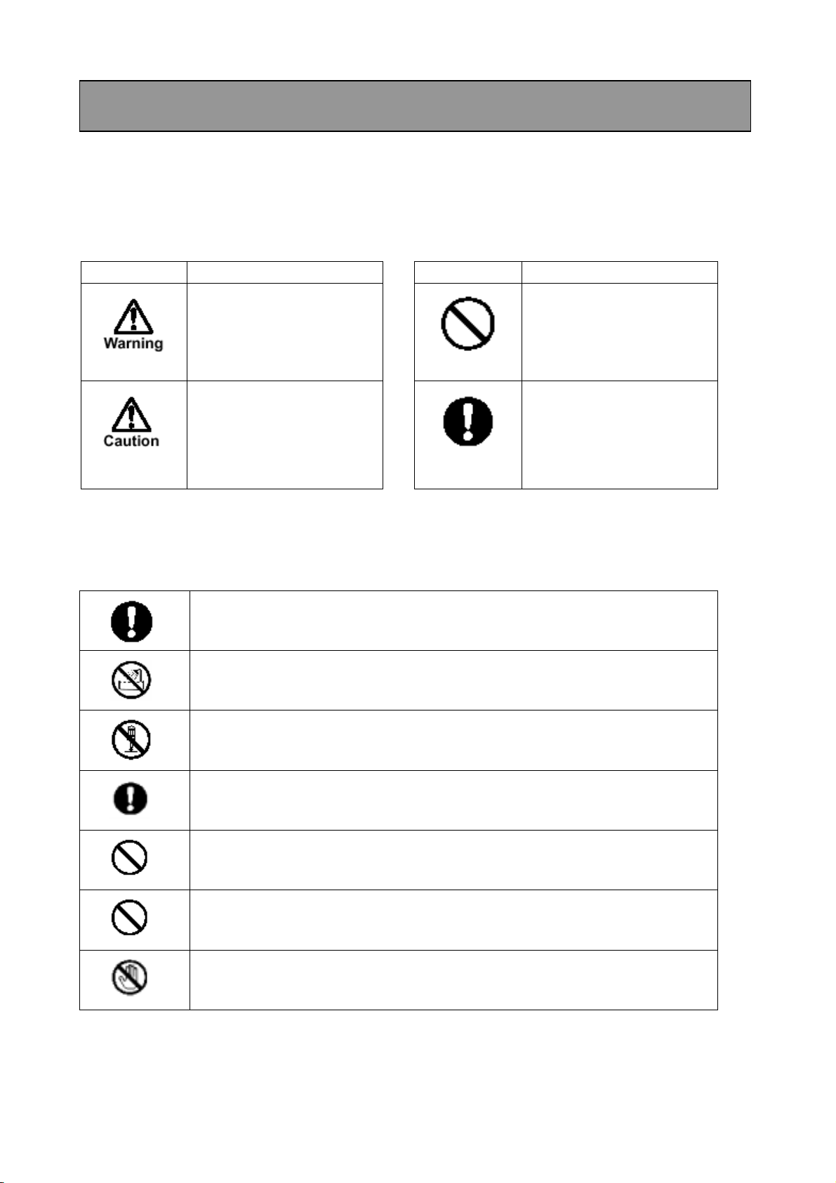
Indication definitions Graphic symbol definitions
Indication Meaning Symbol Meaning
This indicates that ignoring
this label and/or
misoperation of the product
may cause serious personal
injury or even death.
This indicates that ignoring
this label and/or
misoperation of the product
may cause personal injury
and/or material damage.
*1
*2
*1: Bodily injury means injuries, burns, and electric
shock which does not require hospitalization or
prolonged treatment.
*2: Physical damage means extended harm to home,
household effects.
• Do not use the product when abnormality occurs.
The use in the abnormality status such as emitting smoke from the product, smelling burning, being
damaged by drop, invasion of foreign objects inside the product, etc., may cause fire and/or electric
shock. Be always sure to remove the AC adapter at once and contact your dealer.
Indicates a prohibited action
that must not be carried out.
The actual prohibited action
is indicated in the symbol or
nearby graphically or
described in text.
Indicates a mandatory action
that must be carried out
surely. The actual mandatory
action is indicated in the
symbol or nearby graphically
or described in text.
• Do not install the product near water – for example, near a bathtub, kitchen sink, laundry tub,
wet basement, swimming pool, etc.
This may cause fire and/or electric shock.
• Do not repair, disassemble and/or modify yourself.
Do not attempt to service this product yourself as opening or removing covers may expose you to
dangerous voltage or other hazards. Refer all servicing to qualified service personnel.
• Use the AC adapter only with the indicated power supply voltage.
This product should be operated only from the type of power source indicated on the marking label. If
you are not sure of the type of power supply to your location, consult your product dealer.
• Do not put a vessel(s) filled with a liquid (flower vase, etc.).
If a liquid enters the product, a fire and/or electric shock may occur.
• Do not put the product in an unstable, slanting and/or vibrated place.
Drop and/or fail of the product may cause injury.
• Do not touch power or TV antenna cords during a thunderstorm.
This might cause electric shock.
5
Page 7
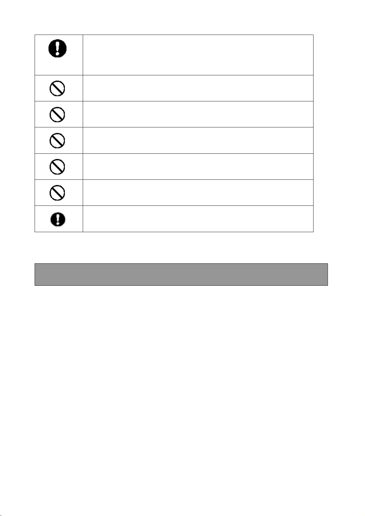
• Observe the following when installing.
• Do not put the product on an inflammable material such as carpet or blanket.
• Do not put the product in a narrow space, since the heat generated from the product may be difficult
to emanate.
• Do not put an inflammable material on the product.
If you do not follow above, the heat generated by the product may cause fire.
• Do not put the product in direct sunshine and/or high temperature.
The temperature rise inside the product may cause fire.
• Do not put the product in a moist or dusty place such as a bathroom, a place close to a
humidifier, etc.
This may cause fire and/or electric shock.
• Do not put the product in a moist, soot and/or dusty place such as a kitchen, etc.
Do not put the product where a soot and steam may occur, such as a kitchen, etc., or in a dusty place.
This may cause fire and/or electric shock.
• Do not allow children to play with the packaging boxes, packaging bags, or other materials.
Failing to do so may result in injury or suffocation.
• Do not stand on the equipment.
Doing so could cause it to crack, break, or could result in injury.
• Ask your dealer to perform a periodical check and internal cleaning.
Dust inside the product may cause fire and/or trouble. For check and cleaning cost, please consult your
dealer.
DISCLAIMER
We disclaim any responsibility and shall be held harmless for any damages or losses incurred by the
user in any of the following cases:
1. Fire, earthquake or any other act of God; acts by third parties; misuse by the user, whether
intentional or accidental; use under extreme operating conditions.
2. Malfunction of non-function resulting in indirect, additional or consequential damages, including but
not limited to loss of expected income and suspension of business activities.
3. Incorrect use not in compliance with instructions in this instruction manual.
4. Malfunctions resulting from misconnection to other equipment.
5. Repairs or modifications made by the user or caused to be made by the user and carried out by a
unauthorized third party
6. Notwithstanding the foregoing, Toshiba’s liabilities shall not, in any circumstances, exceed the
purchase price of the product.
6
Page 8

IMPORTANT PRECAUTIONS
COPYRIGHTS
Using surveillance cameras to record certain images, and the subsequent publication, distribution or
exhibition of such images, including, but not limited to, items in art exhibits, performing arts,
photographs and printed materials, may require the permission of the owners of the rights to said
images, subject to copyright law or other applicable laws.
Save Original Packing Materials
The original shipping carton and packing materials will come in handy if you ever have to ship your
DVR. For maximum protection, repack the set as it was originally packed at the factory.
Daily or weekly Maintenance
Please sometimes check a recorded content.
Hard disks and Fans
In order to maintain recorded content and machine itself, and to prevent troubles, replacement of hard
disks and fans in 3 years is the recommendation but not guarantee.
7
Page 9

1. PRODUCT FEATURES
1.1 Product Introduction
This DVR uses hard disk drives instead of VCR tapes to store digital video images. It enables you to
enjoy the extreme flexibility of digital image archiving instead of clumsy tape management, and is
absolutely compatible with most multiplexers in the market. Equipped with a wide range of
comprehensive features, such as playback picture-by-picture, quick access video recording by time and
event, the upgradeable software, the expandable capacities of the hard-disk drive, and much more, the
DVR will make your applications far more flexible and effective than ever before. For everyone, this
DVR is going to prove the timely substitute for Time-lapse VCR.
1.2 Product Features
Stores video on hard disks instead of VCR tapes.
Maximum 3 Hard Disks capability. (One removable)
Hard disk hot-swapping capability
Pre-alarm image recording
Capable of working with various known multiplexers.
Time-lapse and real-time recording.
Refresh rate up to 60 FPS (50 FPS for PAL).
Image quality selectable at 3 different levels for recording.
Schedule/Manual/Alarm/Continuous recording mode.
Quick search by time, alarm, event, and recording list.
Fast and slow playback of recorded video at various speeds.
Single-frame playback.
On-screen main menu, title and system timer
Password protection.
Critical image archiving through 1.44 MB floppy drive.
Disk-full warning and operation status LEDs.
RS-232 communication port.
Power interruption recovery.
Operation-status record log.
8
Page 10
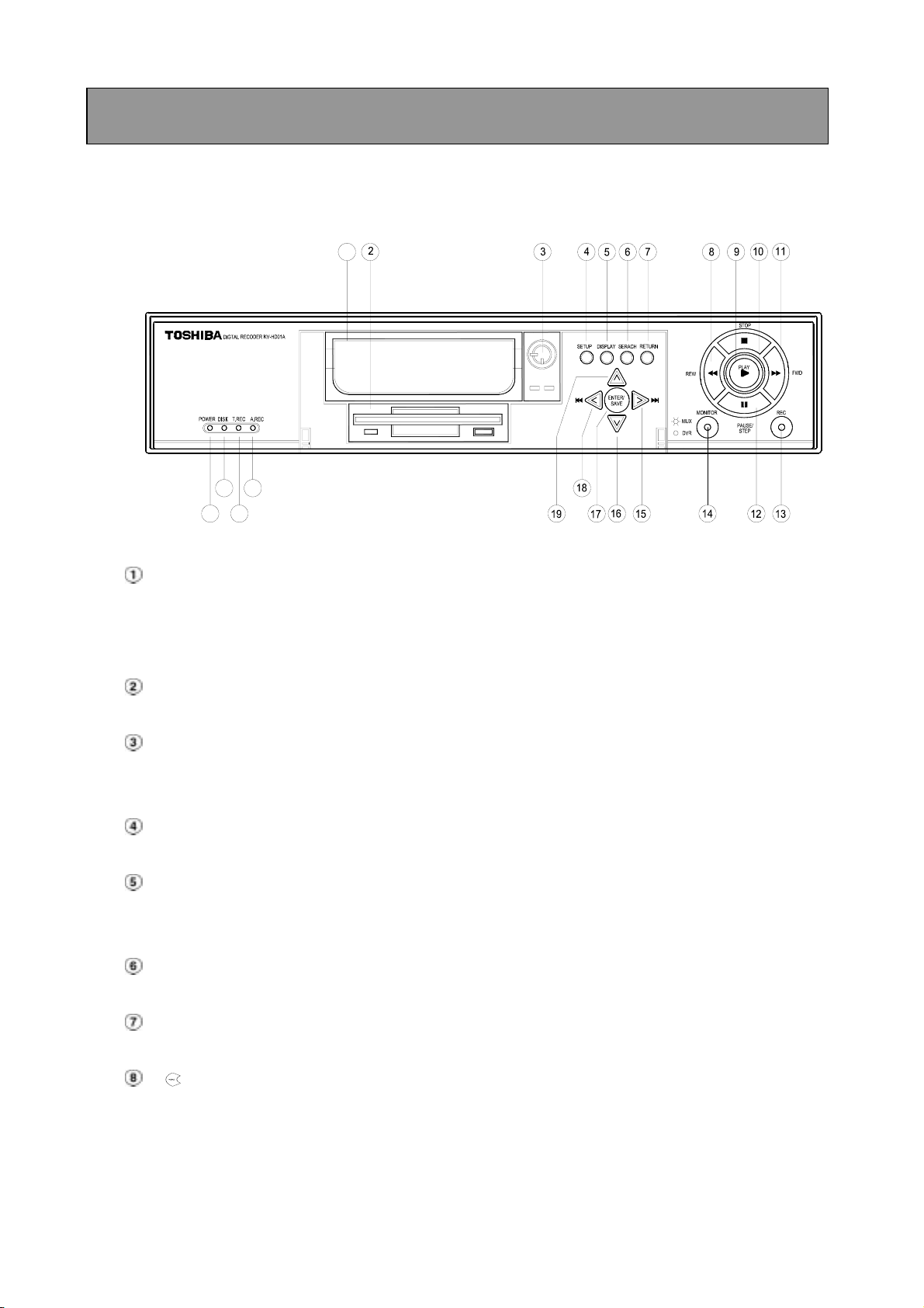
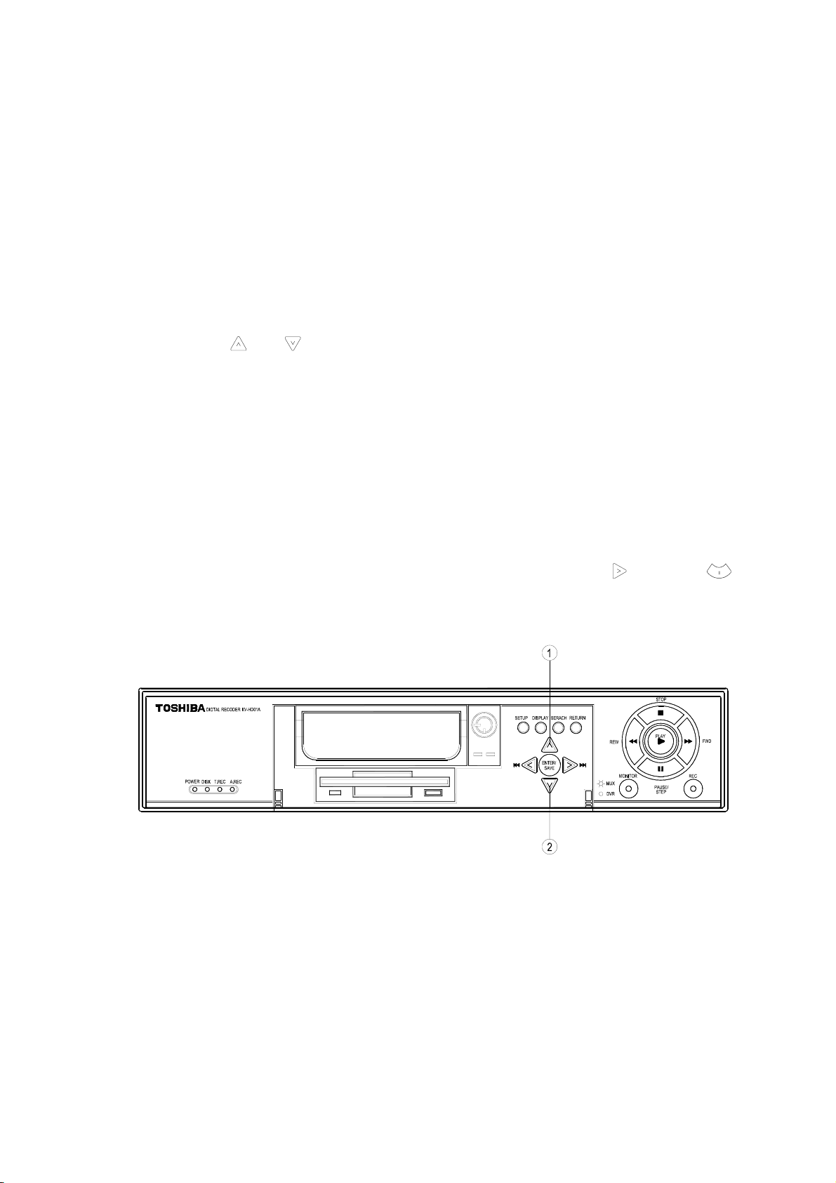
2. DESCRIPTION OF THE FRONT/REAR VIEW
2.1 Front View
1
22
20
23
21
Hard-disk drive compartment.
This compartment allows you to install a drive for backup purposes or additional storage. Make
sure the drive is well secured with the mounting screws in the mobile rack before you put the rack
into the compartment. And remember to turn on the power of the compartment by locking it.
1.44 floppy disk drive. This 1.44 floppy disk slot is used for the system software updating and
critical images archiving.
Hard disk compartment lock:
To secure a hard disk in place. Unlock this compartment before you remove the hard disk from
the slot without turning off the device.
SETUP button:
Press this to enter the main menu. Press again to exit the setup mode.
DISPLAY button:
Push this to show the system operation status on the screen. (Please refer to section 3.3 for
details)
SEARCH button:
Press this to enter the search mode for accessing recorded video.
RETURN button:
Press to leave the current setup page and return to the previous page.
REV button:
Press this to play a video in the reverse direction at faster or slower speeds than the recorded
speed. Each subsequent press of the REV button increases or slows the rate.
9
Page 11

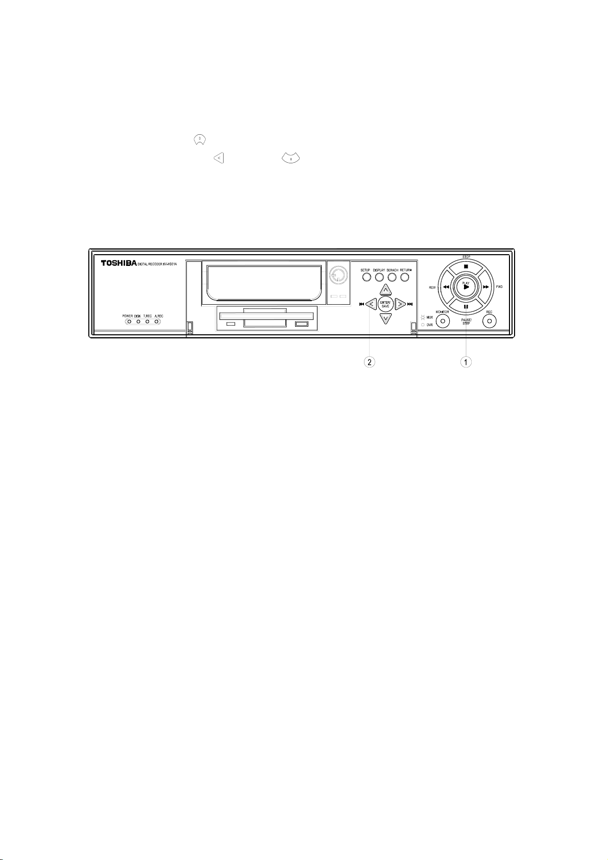
PLAY button:
Press to play back a recorded video from the hard disk. While playing back the recorded video at
faster or slower speeds than the recorded speed, press this button to return to the regular
playback speed.
STOP button:
Press this to stop playing back a recorded video.
FWD button:
Press this to play a recorded video in the forward direction at faster or slower speeds than the
recorded speed. Each subsequent press of the FWD button increases or slows the rate.
PAUSE / STEP button:
In a playback display, press this to freeze the display. During the freeze, press this to display one
frame/field of a picture at a time in the forward direction.
REC button:
Push this to start recording the video into hard disks while in the live display mode.
MUX / DVR button:
When connected to a multiplexer, press the MUX/DVR button to switch between the multiplexer
decoded video and the encoded video to be displayed. When the button light is on it indicates the
DVR is displaying the decoded video (The pictures are not multiplexing). In this mode, the unit
doesn’t display the OSD message of the unit on the screen. However, it doesn’t affect the DVR’s
OSD message that is recorded into hard-disk drive. When the button light is off it indicates the
DVR is displaying encoded video (The picture is switching swiftly).
Right / Left buttons:
Press these two buttons to highlight desired items in the menu setup mode. For Key Lock
operation, simultaneously press these two buttons once to lock the unit; to release Key Lock,
simultaneously press these two buttons again.
Up / Down buttons:
Press these two buttons to select the desired contents for programming in the menu setup mode.
ENTER
/
SAVE
ENTER/SAVE Button:
Press to enter the selected item and save the setting in the menu setup mode. During the
playback of a video, if you wish to save a specific image to a floppy disk, press the PAUSE button
to freeze the picture first and then press this button to save the image to a floppy disk.
Indicator of Alarm Recording Mode:
When the scheduled record setting is on, the indicator will light.
Indicator of Timer Recording Mode:
When the alarm record setting is on, the indicator will light.
Indicator of Hard Disk Status:
Indicates the operation status of the hard-disk drives. Green light indicates the hard-disk drive is
storing or retrieving the data. Red light signals the hard disk is reaching capacity.
Power Indicator:
Indicates the power status of the DVR.
10
Page 12
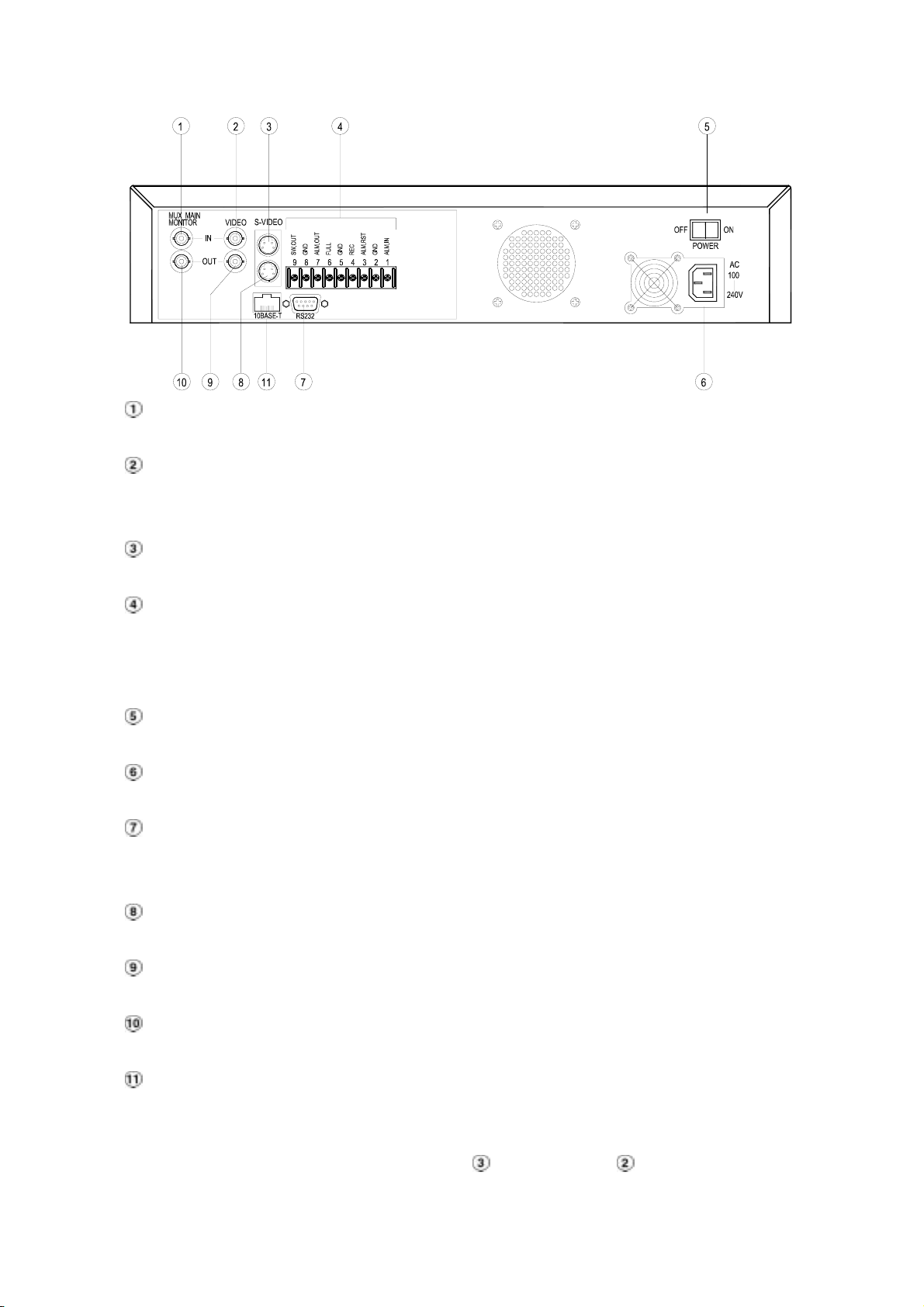
2.2 Rear View
MUX MAIN MONITOR IN Connector:
This BNC connector is used to connect the live video output from a multiplexer to the unit.
VIDEO IN Connector:
This BNC connector is used to connect the video output from a camera or a multiplexer to the
unit.
S-VIDEO IN Connector:
This connector is used to connect the S-video output from a camera or a multiplexer to the unit.
Terminal Block:
There are 9 exposure contacts on this terminal block including SW. Out, GND, ALM. OUT, FULL,
REC, ALM RST, GND, and ALM. IN for connecting with external devices. Please refer to the next
section for details.
Power Switch:
To power the unit on or off.
Plug Outlet:
For connecting with an external power supply.
RS-232 Port:
RS-232 communication port for connecting with an external control device. Please refer to
APPENDIX 1 for more details.
S-VIDEO OUT Connector:
This provides a S-video signal to a multiplexer.
VIDEO OUT Connector:
This provides a composite video signal to a multiplexer.
MONITOR Connector:
This provides a composite video or a multiplexer’s live signal if connected to a display device.
10 BASE-T Connector:
This is a standard RJ-45 connector for 10 Mbps Ethernet networks.
NOTE: The DVR only processes the S-VIDEO IN signal when receiving video signals
simultaneously from both “S-VIDEO IN
” and “VIDEO IN ” connectors.
11
Page 13

2.3 Terminal Block
GND
SW.OUT
ALM.OUT
FULL
GND
REC
ALM.RST
GND
ALM.IN
123456789
1. ALM IN: (INPUT)
This is an alarm input, which can be programmed in the menu system to Normally Open or Normally
Closed. (Active low, 5V)
2. GND:
Ground Contact.
3. ALM RST: (INPUT)
This terminal connects to an alarm-clear device for clearing the alarm. (Active low, 5V)
4. REC: (INPUT)
This terminal connects an external switch to turn the recording function of the DVR on/off. (Active low,
5V)
5. GND:
Ground Contact.
6. FULL: (OUTPUT)
This terminal sends out the full-disk signal. (Active low, 5V)
7. ALM OUT: (OUTPUT)
This is an alarm output relay. Connect this to an external device like buzzers or lights. (Active low,
5V)
8. GND:
Ground Contact.
9. SW OUT: (OUTPUT)
This terminal, sending out the timing signal (falling/negative) to a multiplexer. Connect this terminal
to a multiplexer’s trigger terminal so that the multiplexer can switch to use the same recording speed
as the DVR.
12
Page 14
3. INSTALLATION
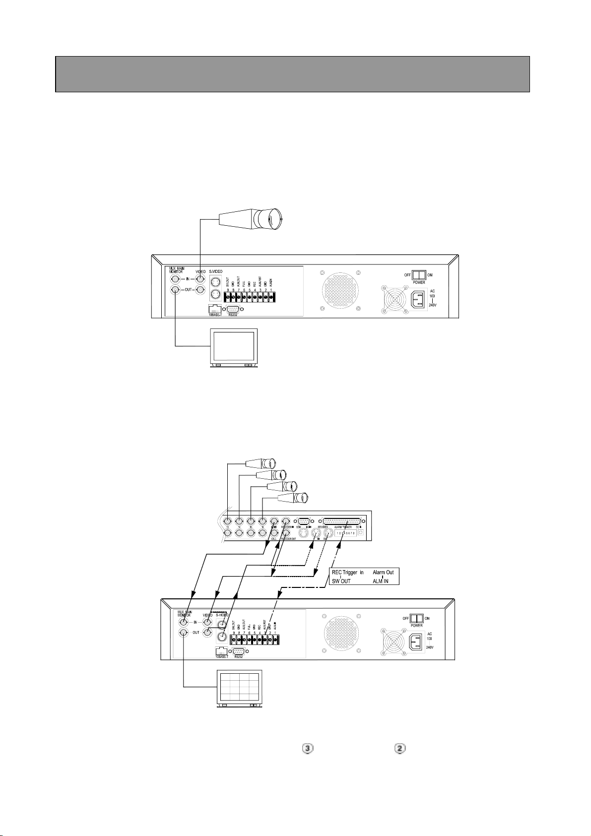
3.1 Basic Connection
CONNECTING WITH A SINGLE CAMERA (OR A QUAD PROCESSOR)
Please set the MULTIPLEXER option to OFF on the REC Setting page in the main menu. (Please
refer to section 5.3 MULTIPLEXER option)
Single Camera
Monitor
CONNECTING WITH A MULTIPLEXER
To match the multiplexer’s recording speed, please set the MULTIPLEXER option to ON on the REC
Setting page in the main menu when the DVR is connected with a multiplexer. (Please refer to section
5.3 MULTIPLEXER option)
Cameras
Monitor
NOTE: The DVR only processes the S-VIDEO IN signal when receiving video signals
simultaneously from both “S-VIDEO IN
” and “VIDEO IN ” connectors.
13
Page 15

3.2 System Information
You can display system settings information as shown on Table 3.2 A below at any time by pressing
the DISPLAY button
. However, when the unit is displaying a decoded image from a multiplexer, you
must first switch the unit to encoded image displaying (The pictures is switching swiftly and the light
of
MUX/ DVR button is off) by pressing the MUX/ DVR button . Each sequential press of the
DISPLAY button displays a different message detailed in the following example. By default, the unit
displays time, date, and an indicating bar of capacity status on a monitor as shown next.
Default display
(Capacity Used) (Capacity Remaining)
09- 05-2001 16:13:02
(Date) (System Time)
Press the DISPLAY button once; the unit will display the following sample message plus the default
display. Press the DISPLAY button again; the unit will not display any OSD message. Press the button
one more time to back to the default display.
Table 3.2 A. Description of Table 3.2 A
HD 1+HD 2: 76G 11.2 HR
(HD1+HD2: 76GB): Total capacity of installed hard disk, 76 GB
QUALITY: HIGH NTSC
RATE: 6 HR 20 F/S
HD P SIZE POS
1 Y 38 G 2.5%R (P)
2 Y 38 G 0%R (P)
3 . .
(11.2 HR):
time available. Actual recording time may be
longer in everyday use.
( ): Timer record activated
): Alarm record activated
(
(QUALITY: HIGH): Record quality setting, HIGH
(NTSC): NTSC system
(RATE: 6 HR): Setting of Record time mode, 6 hours
(20 F/S): Record speed setting, 20 fields/sec
(HD): Hard disk Compartment
(P): Y Hard disk installed; . No hard disk installed
(SIZE 38GB): The capacity of the installed hard disk
POS: Percentage of system; R: Recording; P: Playback
Total 11.2 hour minimum guaranteed recording
14
Page 16
3.3 Updating System Software
If the system software of the unit needs to be upgraded, please take the following steps to safely
update it.
Important: Before carrying out the following procedures, please ensure the floppy disk is working and
the file of system software is intact (The size of the file should be up to 170 K.)
1. Turn off the unit.
2. Insert the floppy disk into the built-in floppy drive of the unit.
3. Hold down the
4. Keep holding down the buttons until the unit sounds a tone and display the message “ SOFTWARE
UPDATE” and an indicating percentage of proceeding against a blue background on the screen.
Now the unit is updating the system software, which will take approximately 90 seconds to process.
5. Restart the unit when the device sounds a tone twice and displays the message “ PLEASE
RESTART”. The process is complete.
(If you have already followed the procedure 1~5, the unit, however, is not being able to power on.
Please first check if the floppy disk you are using is functioning and the file is intact. And then start
the procedure 1 ~ 5 all over again.)
6. Verify the version of system software by entering main menu and then press
buttons at the same time.
and buttons simultaneously, and then turn on the unit.
and pause
Warning: Don’t Interrupt the process while the unit is updating itself and proceed with a floppy
disk containing with no system software of the unit, which would cause the unit hang
on.
15
Page 17
3.4 Video format (NTSC/PAL) selection
If the video format (NTSC/PAL) of the unit needs to be changed, pleases take the following steps.
If the unit is currently set to NTSC;
1, Push stop
2, Hold down the
3, OSD massage "SET PAL, PLS RESTART" appears.
4, Restart the unit. The video format is now set to PAL.
To revert back to NTSC, repeat process.
Note: Video recorded in PAL format will not playback on NTSC setting. Likewise video
recorded in NTSC will not playback on PAL setting. It is recommended to reformat
HDD after changing video format.
button.
and pause buttons simultaneously.
16
Page 18

4. BASIC OPERATIONS
This section shows you how to operate and manage the unit when it gets in the way.
4.1 Configuring Recording Settings
Recording Time settings (Recording Rate and Picture Quality Setting)
Recording time will vary depending on the image size, recording rate, and the capacity of hard-disk
drive. This unit ships with a 80GB hard disk for continuous recording from one to eight weeks under
most recording conditions. The table below shows recording times based on the 80GB hard-disk drive
at certain refresh rates and the corresponding image quality. With one or more hard-disk drives in
operation, please calculate the recording time using the table below in accordance with your
requirements. For a NTSC unit, for example, if the unit is set to record images with HIGH quality at a 60
fps record rate, normally a 80GB hard-disk drive will be filled in 12 hours (See the gray area in the
table). In a 2nd 80GB hard disk drive is added, under the same refresh rate and picture quality, both
drives will be filled in 24 hours.
Set up the REC Time Mode when a multiplexer is connected
For optimum image recording and playback when a Multiplexer is used, the record speed of the
multiplexer must be correctly adjusted to match the unit. Set the MULTIPLEXER option on the main
menu to ON. This can be done one of the two methods detailed below.
(1) If an Toshiba multiplexer is connected for use, you can program the REC time mode of the
multiplexer by referring to the table below (each refresh rate refers to one REC time mode).
(2) For a multiplexer other than Toshiba. Please, connect the SW. OUT terminal on the rear panel of the
DVR to the multiplexer’s trigger contact. The DVR will provide the timing signal (Negative/Falling) to
the multiplexer. Thus, if the DVR changes the recording speed, the multiplexer will automatically
adjust the record to match. The DVR doesn’t provide a 2-hour timing signal in NTSC or 3-hour
timing signal in PAL.
NTSC System
Possible Recording Time HDD=80 Gigabytes
Refresh Rate (Field/Sec) 60 20 10 5 2.5 1.25 0.625 0.25 0.16 0.125
Image
Quality
REC Time Mode 2 hr 6 hr 12 hr 24 hr 48 hr 96 hr 168 hr 480 hr 720 hr 960 hr
REC interval (1/60 sec) 1 3 6 12 24 48 84 240 360 480
HIGH 12 hr 36 hr 72 hr 144 hr 288 hr 576 hr 1008 hr 2880 hr 4320 hr 5760 hr
STANDARD 18 hr 54 hr 108 hr 216 hr 432 hr 864 hr 1512 hr 4320 hr 6480 hr 8640 hr
BASIC 24 hr 72 hr 144 hr 288 hr 576 hr 1152 hr 2016 hr 5760 hr 8640 hr 11520 hr
17
Page 19

PAL System
Possible Recording Time HDD=80 Gigabytes
Refresh Rate (Field/Sec) 50 25 12.5 6.25 3.13 1.56 0.89 0.31 0.21 0.16
HIGH 14 hr 28 hr 54 hr 112 hr 224 hr 448 hr 784 hr 2240 hr 3360 hr 4480 hr
Image
Quality
REC Time Mode 3 hr 6 hr 12 hr 24 hr 48 hr 96 hr 168 hr 480 hr 720 hr 960 hr
REC interval (1/50 sec) 1 2 4 8 17 32 57 161 241 321
STANDARD 22 hr 44 hr 88 hr 176 hr 352 hr 704 hr 1232 hr 3520 hr 5280 hr 7040 hr
BASIC 28 hr 56 hr 112 hr 224 hr 448 hr 896 hr 1568 hr 4480 hr 6720 hr 8960 hr
4.2 Recording Operations
This section details the way to record video into hard-disk drives. Before commencing with the
recording function, please configure the recording setting properly according to your needs.
4.2.1 Manual Recording
When the unit is in the live display mode, take the following steps to start recording:
(1) In live display, press the REC button
corresponding programmed recording settings. The monitor should display a flashing REC message
and the REC button will light up indicating the unit is in the recording status.
(2) Press the
STOP button to stop recording any time.
(3) To access just recorded video, please refer to section 4.4 for more details.
to record video onto a hard disk drive with the
18
Page 20

4.2.2 Timer Recording
Timer recording provides two periods of time each day in a weekly table which programs the DVR to
turn on and off at specified times. This way the DVR will start and stop recording according to the
programmed schedule. Please take the following steps to program the scheduled recording.
(1) Press the SETUP button
(2) Select the RECORD TIMER and press the ENTER/SAVE button
to enter the MAIN MENU.
to enter the TIMER page.
(3) Select the TIMER-SET.
ENTER
/
(4) Press the
(5) Use the
SAVE
ENTER/SAVE button to enter the REC SCHEDULE table.
button and the button to locate the specific day/hour/minute and use the
button and the button to set the day/hour/minute you wish. The time is displayed in
a 24-hour clock format.
ENTER
/
SAVE
(6) After scheduling is completed, press the
ENTER/SAVE button and set OK to save the
setting or select CANCEL to leave the page without saving the settings.
(7) To activate the programmed recording schedule, set the REC ENABLE to ON. As the scheduled
recording is on, the red indicator of the Timer Record will be on as well. To deactivate it, set to OFF.
(8) Press the
continue the scheduled recording, press the REC button
STOP button during the scheduled recording to stop it at any time. If you wish to
to proceed.
NOTE: You can proceed to start the scheduled recording from the current time if it is in the
scheduled interlude as soon as setting is completed. Press the REC button to proceed.
NOTE: If you activate the recording function before the scheduled recording, the unit will
operate recording as showed the diagram below and keep those Image in different files.
03:0 0 06:00 08 :00 12:00 14:00
START END START END
Start Manual
Recording
Timer Manual Timer Manual
19
Page 21

TIME/ TITLE
RECORD TIMER
RECORD
ALARM
COMMUNICATION
DISK
SYSTEM
GO TO TIMER PAGE
MAIN MENU
REC ENABLE
TIMER---------------------------- SET
MAIN PAGE
SET REC TIMER
RECORD TIMER
MAIN MENU
TIME/ TITLE
RECORD TIMER
RECORD
ALARM
COMMUNICATION
DISK
SYSTEM
GO TO TIMER PAGE
RECORD TIMER
REC ENABLE------------------ ON
TIMER
MAIN PAGE
TIMER REC ENABLE
START END START END
S : 00-00:00-00 00:00-00:00
M: 00-00:00-00 00:00-00:00
T : 00-00:00-00 00:00-00:00
W: 00-00:00-00 00:00-00:00
T : 00-00:00-00 00:00-00:00
F : 00-00:00-00 00:00-00:00
S : 00-00:00-00 00:00-00:00
←→ TO MOVE ↑↓ TO CHANGE
REC SCHEDULE
20
Page 22

4.2.3 Alarm Recording
Take the following steps to activate the programmed alarm recording. For ALM REC RATE, ALM REC
QUALITY, ALARM STATUS, ALM DURATION, and PRE-ALARM settings, please refer to section 5.4
for more details.
(1) Press the SETUP button
(2) Select ALARM and press the
to enter the MAIN MENU.
ENTER
/
SAVE
ENTER/SAVE button to enter the ALARM SETTING.
(3) Set the desired REC RATE, REC QUALITY, ALM TYPE, and ALM DURATION for use. If pre-alarm
recording is required, set PRE-ALARM to ON.
(4) To activate the alarm recording, set ALARM OPERATION to ON. To deactivate it, set ALARM
OPERATION to OFF.
MAIN MENU
TIME/ TITLE
RECORD TIMER
RECORD
ALARM
COMMUNICATION
DISK
SYSTEM
GO TO ALARM PAGE
ALARM SETTING
ALM OPERATION : OFF
REC RATE : 60F/S
REC QUALITY : HIGH
ALM TYPE : NO
ALM DURATION : NON STOP
PRE- ALARM : OFF
MAIN PAGE
ALARM REC ENABLE
4.2.4 Externally triggered Recording
You can use an external switch to turn the recording function of the DVR on/off to record video into the
hard-disk drive by connecting the REC exposure contact on the rear panel of the DVR. Please refer to
section 2.3 for more details.
21
Page 23

NOTE: The status of recording operations as showed the diagrams below when an alarm takes
m
place.
Manual or Externally
1
Triggered Recording
Alarm Takes Place
Actual Recording
Speed
Normal Alarm Normal
2
Timer Recording
Alarm Takes Place
Actual Recording
Speed
Normal Alarm Normal
3
Timer Recording
Alarm Takes Place
Actual Recording
Speed
Normal Alarm
4
Timer Recording
Alarm Takes Place
Actual Recording
Speed
Alar
Normal
22
Page 24

4.3 Playback Operations
This section shows you how to operate the fast, slow, and single-picture playback functions, and details
how the unit is to playback a file in different operation status. Please refer to the following paragraphs
specifying the relevant details. When playing a file, the monitor should display a flashing PLAY
message and the
PLAY button will light up indicating that the unit is in the playback status.
Operation Status
A. From REC mode to Playback mode
(In live mode, directly press “PLAY” button to play a latest recorded video)
REC→ [Stop] → [Play] .................................................................... Play the latest recorded file
[Play: to the end of the file] ................ Show the ending message
(Using search function to replay
the file if required)
[Stop] → [Play] ................................. Play the file from the stop position
B. Search to play back a particular recorded video
Search→ [Play] ................................................................................ Play a selected file
[Play to the end of the file] .............................. Show the ending message
(Search again to replay the file if
required)
[Stop] → [Play] .............................................. Play the file from the stop position
C. Play Back From The Oldest Data
[Stop: Press the “STOP” button for three seconds] → [Play] ............. play back the oldest recorded video
4.3.1 Fast Forward/Reverse
There are 5 speeds available for playback: 2x, 4x, 8x, 16x, and 30x.
While playing back recorded video at recorded speed:
Forward: Press the
faster than the recorded speed. Each subsequent press of the
rate.
Reverse: Press the
faster than the recorded speed. Each subsequent press of the
the rate.
Normal: Press the
FWD button to view the recorded video in the forward direction at a speed
FWD button increases the
REV button to view the recorded video in the reverse direction at a speed
REV button increases
PLAY button to return to the normal speed of playback.
23
Page 25

NOTE: The playback speed will be displayed on the screen. However, when playing a recorded
video from a multiplexer, the playback speed only display on encoding (multiplexing)
mode. Press the
mode.
MUX / DVR button to switch between decoding and encoding
4.3.2 Slow Forward/Reverse
There are 4 speeds available for a slow playback: 1/2, 1/4, 1/8, 1/16. Follow the instructions below to
proceed with a slow playback.
While playing back recorded video at the recorded speed:
(1) Press the
(2) Forward: Press the
(3) Reverse: Press the
(4) Normal: Press the
PAUSE/STEP button for the slow playback mode.
FWD button to view the recorded video in the forward direction at a
speed faster than the recorded speed. Each subsequent press of the FWD button slows
the rate.
REV button to view the recorded video in the reverse direction at a
speed faster than the recorded speed. Each subsequent press of the REV button slows
the rate.
PLAY button to return to the normal speed of playback.
4.3.3 Play Back Picture-by-picture
While playing back recorded video at the recorded speed:
(1) Press the
(2) Press the
forward direction. (When playing back recorded video recorded by a multiplexer, each
sequential press of the
(3) Press the
NOTE: A flickering condition of an image occurs while playing back picture-by-picture, please
set the FLICKER REDUCTION option to ON in the SYSTEM page of the main menu.
However, when this function is activated, a slight loss of picture quality may occur.
PAUSE/STEP button for the picture-by-picture mode.
PAUSE/STEP button to display one frame/field of a picture at a time in the
PAUSE/STEP button will display each camera in sequence.)
PLAY button to return to the normal speed of playback.
24
Page 26

4.3.4 Play Back Recorded Video from a HDD of the mobile rack
To play back a recorded video from a HD3, take the following steps:
(1) Press setup button to enter the main menu.
ENTER
/
(2) Select DISK and press the
SAVE
ENTER/SAVE button to enter DISK SETTING page.
(3) Set the HD3 USAGE to REC/PLAY and then exit the main menu.
(4) Use the Search function to access desired recorded video. Specific operation details please refer to
the next section 4.4 Search Operations.
4.4 Search Operations
This section shows you how to access recorded video.
4.4.1 Full List Search
Take the following steps to proceed with the full list search function.
(1) Press the SEARCH button
(2) Select the FULL LIST and press the
to enter the search mode.
ENTER
/
SAVE
ENTER/SAVE button to access the complete list of
recorded video.
(3) Highlight the specific recorded video of your requirement and press the
to display the selected video.
(Key Operation: Press
buttons
to flip over a page.)
Up/Down buttons to select a video; Press Right / Left
SEARECH
FULL LIST
ALARM LIST
TIME SEARCH
HD 1
2001-02-01 12: 20
A 2001-02-01 13:30
2001-03-02 14:20
2001-03-02 14:20
R 2001-03-02 14:20
HD 2
T 2001-02-01 13:30
ENTER
/
SAVE
ENTER/SAVE button
NOTE: T: Timer recording; R: External trigger recording; A: Alarm recording.
25
Page 27

4.4.2 Alarm list Search
Take the following steps to proceed with the alarm list search function.
(1) Press the SEARCH button
(2) Select the ALARM LIST and press the
to enter the search mode.
ENTER
/
SAVE
ENTER/SAVE button to access the complete list of
alarm-event recorded video.
(3) Highlight the specific recorded video of your requirement and press the
to display the selected video.
(Key Operation: Press
buttons
to flip over a page)
Up/Down buttons to select a video; Press Right / Left
SEARCH
FULL LIST
ALARM LIST
TIME SEARCH
A 2001-02-01 12: 20
A 2001-02-01 13:30
A 2001-03-02 14:20
ENTER
/
SAVE
ENTER/SAVE button
4.4.3 Time Search
Take the following steps to proceed with the alarm list search function.
(1) Press the SEARCH button
(2) Select the TIME SEARCH and press the
page.
(3) Set the time period you wish to search for the recorded video.
ENTER
/
(4) Press the
SAVE
ENTER/SAVE button to start searching and displaying the concerned image.
(5) If no video is found, please return to the time setting page and repeat steps (3) and (4) again for
another search.
SEARCH
FULL LIST
ALARM LIST
TIME SEARCH
to enter the search mode.
ENTER
/
SAVE
ENTER/SAVE button to access the time setting
TIME SEARCH
MM DD YEAR HH MM
08 17 2001 00:00
26
Page 28

4.5 Data Backup
4.5.1 Backup Operations
There are three ways available to duplicate the recorded video from HD 1 and HD 2 to HD 3.
Please take the following steps to proceed.
(1) Set HD 3 to BACKUP first. Take the following steps.
Press the SETUP button to enter the setup mode and select the DISK.
ENTER
/
Highlight DISK and press the
Then set HD 3 USAGE to BACKUP.
SAVE
ENTER/SAVE button to enter the DISK SETTING page.
MAIN MENU
TIME/ TITLE
RECORD TIMER
RECORD
ALARM
COMMUNICATION
DISK
SYSTEM
GO TO DISK PAGE
DISK SETTING
REFORMAT HD 1
HD 3 USAGE---------- BACKUP
BACKUP REC/PLAY
MAIN PAGE
SET HD 3 USAGE
(2) FULL: Duplicating all the recorded video from HD1 and HD 2 to HD3.
Stay on the DISK SETTING page.
Use the Up/Down buttons to highlight BACKUP; select FULL, then press the
ENTER/SAVE button
to proceed.
MAIN MENU
TIME/ TITLE
RECORD TIMER
RECORD
ALARM
COMMUNICATION
DISK
SYSTEM
GO TO DISK PAGE
DISK SETTING
REFORMAT
HD 3 USAGE
BACKUP----------------FULL
ALARM
SELECT
MAIN PAGE
BACKUP ALL TO HD 3
ENTER
/
SAVE
27
Page 29

ALARM: Duplicating all the alarm-event recorded video from HD 1 and HD 2 to HD 3.
Stay on the DISK SETTING page.
Use the Up/Down buttons to highlight BACKUP; select ALARM, then press the
ENTER
/
SAVE
ENTER/SAVE button
to proceed.
MAIN MENU
TIME/ TITLE
RECORD TIMER
RECORD
ALARM
COMMUNICATION
DISK
SYSTEM
GO TO DISK PAGE
DISK SETTING
REFORMAT
HD 3 USAGE
BACKUP----------------FULL
ALARM
SELECT
MAIN PAGE
BACKUP ALARM TO HD 3
SELECT: Duplicating a particular recorded video from HD1 and HD 2 to HD3.
Stay on the DISK SETTING page.
Use the Up/Down buttons to highlight BACKUP, select SELECT and then press the
ENTER
/
SAVE
ENTER/SAVE button to list all the recorded video.
Press the Up/Down buttons to select the desired clip and press the SETUP button to
mark it.
ENTER
/
After completing the selection, press the
SAVE
ENTER/SAVE button to proceed.
MAIN MENU
TIME/ TITLE
RECORD TIMER
RECORD
ALARM
COMMUNICATION
DISK
SYSTEM
A 2001-02-01 12:20
2001-02-01 03:30 +
A 2001-03-02 04:20 +
2001-04-01 13:30
DISK SETTING
REFORMAT
HD 3 USAGE
BACKUP----------------FULL
ALARM
SELECT
MAIN PAGE
BACKUP PART TO HD 3
TOTAL: 41 M
READY TO GO
OK CANCEL
NOTE: If the capacity of HD 3 is not sufficient to store all selected video, a warning message
“HD3 SPACE NOT ENOUGH” will be displayed on the screen. Please, insert a larger
capacity of hard disk drive or erase some data from the drive and start the process over
again.
28
Page 30

4.5.2 Archive Clips into Floppy Disk
Please take the following steps to archive a critical image in a floppy disk.
(1) Insert a 1.44 floppy disk into the floppy slot.
(2) Start playing back the recorded video. (When playing back recorded video made by a multiplexer,
you must to get into the multiplexing mode and display picture by picture to be able to select the
desired image for archiving. Press the
under this mode that the light of
(3) Press the
(4) Press the
PAUSE/STEP button to freeze the desired pictures.
ENTER
/
SAVE
ENTER/SAVE button to save the image in the floppy disk.
MUX/ DVR button to get into the multiplexing mode
MUX/ DVR button is off and the pictures is switching swiftly)
(5) A floppy disk can store approximately 50~100 pictures. You can have the saved images printed out
in any computer. The image is stored in the JPEG compressed format. If more than one clip is
stored in a floppy disk, file names will be assigned in sequence as shown below.
SAVE TO J0001.JPG
SAVE TO J0002.JPG
…
SAVE TO J000N.JPG
4.6 Key Lock Operation
The Key lock operation protects the unit against unauthorized use by disabling the entire front
panel control. Simultaneously press these two
the unit; to release Key Lock, simultaneously press these two buttons again.
and buttons (as shown below) once to lock
29
Page 31

5. MAIN MENU
There are 7 submenus to the MAIN MENU to guide you through the setup of the DVR. The following
sections will instruct you step by step now to configure the operation setting and options. Press the
SETUP button
to access the MAIN MENU. Once inside the menu system, the on-screen menu
allows you to set up the key features of the unit. The functions of various buttons within the Main Menu
mode are described in the paragraphs below.
MAIN MENU
TIME/ TITLE
RECORD TIMER
RECORD
ALARM
COMMUNICATION
DISK
SYSTEM
KEY FUNCTIONS
SETUP button
:
Press to enter the main menu. Press again to exit the setup mode.
RETURN button
:
Press to exit the current setup page and return to the previous page.
Right/Left buttons :
Press to select the desired item or entry for the setting.
Up/Down buttons :
Press to highlight the desired option or to select the context for the setting.
ENTER
/
SAVE
ENTER/SAVE button :
Press to enter the selected item and to save the settings.
30
Page 32

5.1 TIME/ TITLE
This device is able to print inerasable system time and title information directly onto images during
recording. This page allows users to set the time and desired title, and to decide if the function is to be
activated. The entries are listed as follows.
MAIN MENU
TIME/ TITLE
RECORD TIMER
RECORD
ALARM
COMMUNICATION
DISK
SYSTEM
GO TO TIME/ TITLE PAGE
TIME/TITLE
TIME STAMP : OFF
TIME SETTING : SET
TITLE STAMP : OFF
TITLE SETTING : SET
MAIN PAGE
REC TIME STAMP
TIME STAMP :
The Time Stamp option is used to stamp the system time onto images during recording process.
The Time Stamp is inerasable.
ON : Enables the device to stamp the time onto images during recording.
OFF : Disables the stamping function.
TIME SETTING :
This option is used to set the system time and date.
TITLE STAMP :
The Title Stamp option is used to stamp the system title onto images during the recording
process. The Title Stamp is inerasable.
ON : Enables the device to stamp programmed title onto images while recording.
OFF : Disables the stamping function.
TITLE SETTING :
This option is used to set the system title. The Title can consist of up to twelve characters with
the letters A-Z, numbers 0-9 or blank spaces.
NOTE: If you wish to have system-time on an archived image in a floppy, the “TIME STAMP”
option must be set to “ON” for recording.
NOTE: No matter whether the “TIME STAMP” option is set to “ON” or “OFF”, the unit will
always encode the system time into the video while recording. So you can always have
system time to be displayed on the screen by pressing the “DISPLAY” button. However,
if two time messages have overlapped on the screen, please press the “DISPLAY”
button to stop decoding time from the video so that the unit will only display the
stamped time only.
31
Page 33

5.2 RECORD TIMER
The unit provides a weekly table, consisting of two periods of time each day for scheduled recording.
This option allows you to set the time each day that the unit will start and stop recording.
MAIN MENU
TIME/ TITLE
RECORD TIMER
RECORD
ALARM
COMMUNICATION
DISK
SYSTEM
GO TO TIMER PAGE
REC ENABLE :
The rec enable option is used to enable / disable the programmed scheduled recording.
ON: Enables the scheduled recording.
OFF: Disables the scheduled recording.
TIMER :
This option is used to set the time that the unit will start and stop recording each day in a weekly
format. There are two time periods each day available for scheduling. The time is displayed in a
RECORD TIMER
REC ENABLE : OFF
TIMER : SET
MAIN PAGE
TIMER REC ENABLE
24-hour clock format. If there is a time overlap between two continual time period settings, the
device will automatically combine the two time-period settings into one combined time period
setting.
REC SCHEDULE
START END START END
S :06:00-16:00 12:00-18:00
REC SCHEDULE
START END START END
S :06:00-18:00 00:00-00:00
32
Page 34

5.3 REC SETTING
This page allows you to set recording rate and recording quality, and to enable you to continue
recording when the disk is full.
MAIN MENU
TIME/ TITLE
RECORD TIMER
RECORD
ALARM
COMMUNICATION
DISK
SYSTEM
GO TO REC PAGE
REC SETTING
REC RATE : 60 F/S
REC QUALITY : HIGH
DISK FULL : REWRITE
MULTIPLEXER : ON
MAIN PAGE
SET REC RATE
REC RATE:
This option is used for adjusting the number of pictures recorded every second into a hard disk.
The recording rate controls the frequency at which the number of video pictures can be recorded.
For a NTSC unit, there are 10 different recording rates you can select from: 60F/S (60 fields per
second), 20F/S, 10F/S, 5F/S, 2.5F/S, 1.25F/S, 0.625F/S, 1 F/4S, 1F/6S, and 1F/8S. For a PAL
unit, there are two different sets of recording rates for use with a camera or a multiplexer,
respectively. Please refer to the table in section 4.1 for details.
REC QUALITY:
This option is used to determine the quality of the image being recorded. There are 3 levels of
image quality you can select from: HIGH, STANDARD, and BASIC. Selecting HIGH image
quality will result in higher-resolution recorded images, and will normally take up more storage
space than a STANDARD or BASIC quality image does.
DISK FULL:
This option is used to determine the way to utilize storage media in the case that the specified
hard disk is full.
REWRITE: When the hard disk drive is full, the device continues recording by displacing the
old data.
STOP: When the hard disk drive is full, the device will stop recording.
MULTIPLEXER:
For optimum image recording please set this option to ON when the unit connected with a
multiplexer for use. Set this option to OFF when only it is connected with a single camera.
33
Page 35

5.4 ALARM SETTING
This menu allows users to program the configuration of alarm recording only when an alarm input is
activated. The device will record as long as the alarm input is activated.
MAIN MENU
TIME/ TITLE
RECORD TIMER
RECORD
ALARM
COMMUNICATION
DISK
SYSTEM
GO TO ALARM PAGE
ALM OPERATION:
The ALM OPERATION option is used to determine whether to activate/deactivate the alarm
recording when it detects an alarm input.
ALARM SETTING
ALM OPERATION : OFF
REC RATE : 60 F/S
REC QUALITY : HIGH
ALM TYPE : NO
ALM DURATION : NON STOP
PRE-ALARM : OFF
MAIN PAGE
ALARM REC ENABLE
ON: The device activates the alarm recording when it detects an alarm input.
OFF: The device ignores the alarm signal when it detects an alarm input.
REC RATE:
The REC RATE option is used for adjusting the number of pictures recorded every second into a
hard disk when an alarm input is activated. For a NTSC unit, there are 5 different record speeds
you can select from: 60F/S (60 fields per second), 20F/S, 10F/S, 5F/S, and REMAIN. And for a
PAL unit, there are 5 different record speeds you can select from: 50F/S (50 fields per second),
25F/S, 10F/S, 6.25F/S and REMAIN. If you select REMAIN for use, the device will record
images at the same speed as set on the REC page.
REC QUALITY:
The REC QUALITY option is used to determine the quality of the image being recorded. There
are 3 levels of image quality you can select from HIGH, STANDARD, and BASIC. Selecting
HIGH image quality will result in higher-resolution recorded images, and will normally take up
more storage space than a STANDARD or BASIC quality image does. The table below shows
the level of image quality with the corresponding compression ratio and image size.
34
Page 36

ALM TYPE:
The ALM TYPE option is used to set a type of alarm input corresponding to the sensor signal in
use.
NO: Normally Open. This is to be used with the type of alarm sensor, whose contact
remains open in normal conditions and closes in case of activation.
NC: Normally Close. This is to be used with the type of alarm sensor, whose contact
remains closed in normal conditions and opens in case of activation.
ALM DURATION:
The ALM DURATION option is used to set the alarm record mode to record for a certain duration
after the alarm has been deactivated. You can select one of the six following options: 0 SEC,
30SEC, 1 MIN, 5 MIN, 10 MIN, and NON-STOP.
Duration
Setting
Alarm recording
PRE- ALARM:
The PRE-ALARM option is used to determine that images prior to an alarm will be recorded into
the hard-disk drive. If the alarm-recording rate is set to 60F/S, when an alarm is being triggered
the device will record the image prior to the alarm for 3 seconds. If one of the other
alarm-recording rates is set, the pre-alarm image recording will be extended to 5 seconds.
Non-Stop
Alarm
activated
Alarm
activated
Alarm
deactivated
Alarm recording
Alarm
deactivated
Duration
Duration
Reset
ON: Enables pre-alarm recording.
OFF: Disables pre-alarm recording.
35
Page 37

5.5 COMMUNICATION
The COMMUNICATION option is used to configure status of the communication port when the
connected with an external device.
MAIN MENU
TIME/ TITLE
RECORD TIMER
RECORD
ALARM
COMMUNICATION
DISK
SYSTEM
GO TO COMM PAGE
RS232:
The RS232 option is used to determine the activation/ deactivation of the RS232 communication
port for externally triggered recording. To record video into the hard-disk drive connect the REC
exposure contact on the rear panel of the DVR to the switch used to activate the alarm.
MASTER: Sets the KV-HD01A as the master device.
COMM SETTING
RS232 : SLAVE
NET ENABLE : OFF
NET SETTING : SET
MAIN PAGE
SET RS232
SLAVE: Sets the KV-HD01A as the slave device.
NET ENABLE is used to allow remote users viewing privileges over a network or IP.
OFF: Ethernet capability is turned off
ON: Ethernet capability is turned on
NET SETTING is used to set the IP, MASK, and GATEWAY address of the KV-HD01A.
SET: Sets the IP,MASK, and GATEWAY addresses of the KV-HD01A
36
Page 38

5.6 DISK SETTING
MAIN MENU
TIME/ TITLE
RECORD TIMER
RECORD
ALARM
COMMUNICATION
DISK
SYSTEM
GO TO DISK PAGE
REFORMAT:
The REFORMAT option is used to clear out all of the data in the hard disk drive. You will be
required to enter the pre-set password before proceeding with clearing out the data. Enter the
standard password “9999” if you don’t set your individual password. To set your individual
password, please refer to section 5.7 PASSWORD option.
DISK SETTING
REFORMAT : HD 1
HD 3 USAGE : BACKUP
BACKUP : FULL
DISK REFORMAT/CLEAR
HD 1 : Deletes all of the data stored in HD 1.
HD 2 : Deletes all of the data stored in HD 2.
HD 3 : Deletes all of the data stored in HD 3.
HD 1 2 : Deletes all of the data stored in HD 1 and HD 2.
HD 1 3 : Deletes all of the data stored in HD 1 and HD 2.
HD 12 3 : Deletes all of the data stored in HD 1, HD 2 and HD 3.
BACKUP HD : Deletes all of the data stored in HD 3, which is set to backup purpose only. (This
function has to be proceeded when the HD 3 USAGE option is set to BACKUP.)
HD 3 USAGE:
The HD 3 USAGE option is used to determine the way to utilize the hard disk drive in the mobile
compartment HD 3.
BACKUP : Used for data backup only, which will not be part of regular recording hard disk
drive.
REC/ PLAY : Used for regular recording hard disk drive.
Note: When you wish to play back a recorded video from HD3, this option must be set to
REC/PLAY.
BACKUP:
The BACKUP option is used to duplicate data from HD 1 and HD 2 to HD 3.
(For operation details, please refer to section 4.5.1)
37
Page 39

5.7 SYSTEM
V
The SYSTEM PAGE is used for accessing the history of operation status, setting the password,
resuming factory default, and determining the menu display background.
MAIN MENU
TIME/ TITLE
RECORD TIMER
RECORD
ALARM
COMMUNICATION
DISK
SYSTEM
GO TO SYSTEM SETTING
LOG :
This log shows the history of the operation status in chronological order. The operation status is
described to the right of the time of each entry. There are seven possible entries as detailed
below.
ON : The device was powered up.
OFF : The device was powered off.
REC : Recording Started.
STOP : Recording stopped.
PLAY : Recorded Video was played back.
PAUSE : The display was paused.
V-IN : Video input was connected.
V-LOSS : Video loss occurred.
SYSTEM PAGE
OPERATION LOG : ENTER
MENU BACKGND : OFF
FLICKER REDUCT : OFF
BUZZER : OFF
PASSWORD : SET
DEFAULT : LOAD
MAIN PAGE
IEW OPERATION LOG
05/15/01 18:19:32 ON
05/15/01 18:19:32 OFF
05/15/01 18:19:32 REC
05/15/01 18:19:32 STOP
05/15/01 18:19:32 PLAY
05/15/01 18:19:32 PAUSE
05/15/01 18:19:32 V-IN
05/15/01 18:19:32 V-LOSS
05/15/01 18:19:32 P-LOSS
P-LOSS : Power interruption occurred.
MENU BACKGND :
The MENU BACKGND option is used for setting the background display of the menus.
ON : Background is blue.
OFF : Background is transparent.
FLICKER REDUCTION :
The FLICKER REDUCTION option is used to eliminate the flickering condition of an image as it
occurs during a playback picture by picture. Slight picture degradation may occur when using
this feature.
ON : FLICKER REDUCTION is enabled.
OFF : FLICKER REDUCTION is disabled.
38
Page 40

BUZZER :
The BUZZER option is used to determine the embedded buzzer sounding a tone to signal the
following situations. A tone lasts about two seconds long.
Situation Status
Alarm Alarm takes place
Video Loss Video loss takes place
Disk Full Disk is full
Load Default Load factory default
Buzzer Buzzer set to ON
Key Lock Enable/disable key lock function
HD3 Power on /off mobile rack HDD
Backup Backup operation complete
Timer Timer activate/deactivate
HDD Recording switching between HDD
ON : BUZZER is enabled.
OFF : BUZZER is disabled.
PASSWORD:
The PASSWORD option is used to set a 4 digit number password to prevent any unauthorized
re-formatting of the hard disk drives and to use the network viewer.
OLD PASSWORD : Enter the pre-set password (or the standard password if this is the initial
setting) to access the password setting system.
NEW PASSWORD : Enter a 4 digit number password of your choosing which will replace the
pre-set password (or the standard password “9999”).
DEFAULT :
The DEFAULT option is used to reload the factory default setting.
39
Page 41

6. SPECIFICATIONS
Image System NTSC PAL
Resolution 720 x 480 pixels 720 x 576 pixels
Video Input BNC x 2, S-Video x 1
Video Output BNC x 2, S-Video x 1
Storage Media UP to 3 IDE Hard Disks (One mobile Rack)
Image Format M-JPEG
Critical Image Archiving 1.44MB FDD
Recording Rate Up to 60 fields/sec Up to 50 fields/sec
Image Compression High/ Standard/ Basic
Recording Mode Schedule/ Manual/Alarm/Continuous
Pre-Alarm Recording Yes
Fast Forward /Reverse: 1x, 2x, 4x, 8x, 16x, 30x,
Playback Speeds
Access To Recording Full List Search, Time Search, and Event Search
Slow Forward/Reverse: 1/2x, 1/4x, 1/8x, 1/16x
Picture By Picture Playback
Title 12 Characters
On Screen Display & Setup Title/ Time/Date/Main Menu
Alarm Input 1 x NO or NC Contact Programmable
Alarm Output Yes (5V / 0V 5mA max.)
Full-Disk Alarm Output Yes
Trigger Output 1
Operation History Log Up to 2016 events
Key Lock Yes
RS-232 port Yes
Software Upgradeable Yes
Password Control Yes
Power Interruption Recovery
Power Input AC 100~240 V Input (50 Hz/60 Hz); 1 A Max
Automatic Restart After Power Interruption /Recording Operation
Resume
Dimensions 374 x 430 x 90 mm
Operation Temperature 5°~45°C (41°~ 113°F)
40
Page 42

APPENDIX 1. -- RS-232 Protocol
1.Setup
1.1 Use Null Modem cable (The standard RS-232 9 Pin Cable with Pin 2 and Pin 3 exchanged, see
pin configuration chart below for details) to connect the COM 1 on the rear panel of the unit to a PC.
RS-232
1
RX
2
TX
3
4
GND
5
6
RTS
7
CTS
8
9
1.2 Set the RS-232 option to SLAVE in the COMMUNICATION page of the main menu.
1.3 Set communication parameters: 9600 bps, No Parity, 8 Data Bits, 1 Stop Bit.
RS-232
1
RX
2
TX
3
4
GND
5
6
RTS
7
CTS
8
9
2. Communication Protocol:
2.0 General Command Format
<Lead Code = 0x41>, <Main category >, <Second category >, {<Number of parameters>,
<Parameter 1>, <Parameter 2> ..,} <End Code= 0x4f>
Lead Code = 0x41
Main Category = 0x01 Keys and Signals
= 0x02 Command
Second Category = 0x01 Handshake
= 0x02 Request Time/Set Time
= 0x05 Request System State
End Code = 0x4f
The different command types and their corresponding parameters are as follows:
41
Page 43

2.1 Keys and signals
PC Send: <0x41>, <0x01>, <Key Value>, <0x4f>
< The value for a specific front panel key >
KEY_PLAY 1
KEY_STOP 3
KEY_PAUSE 4
KEY_POWER 5
KEY_REC 6
KEY_SETUP 7
KEY_ENTER 8
SET_DEFAULT 9 (reserved)
KEY_SEARCH 10
KEY_DISPLAY 11
KEY_UP 13
KEY_DOWN 14
KEY_LEFT 15
KEY_RIGHT 16
KEY_SCAN_F 19
KEY_SCAN_R 20
KEY_RETURN 21
KEY_MONITOR 36
2.2 COMMAND Types
2.2.0 Command (Main Category=0x02)
2.2.1 Handshake (Second Category=0x01)
PC Request: <0x41>, <0x02>, <0x01>, <0x00>, <0x4f>
DVR Response: <0x41>, <0x02>, <0x01>, <0x00>, <0x4f>
2.2.2 Request Time (Second Category=0x02)
PC Request: <0x41>, <0x02>, <0x02>, <0x00>, <0x4f>
DVR Response: <0x41>, <0x02>, <0x02>, <0x07>, <7 Time Value >, <0x4f>
The following case is an illustration of < 7 Time Value>
2001/06/20 17:05:00 = <0xD1>,<0x07>, <0x06>,<0x14>, <0x11>,<0x05>, <0x00>
42
Page 44

2.2.3 Set Time (Second Category=0x02)
PC Request: <0x41>, <0x02>, <0x02>, <0x07>, < 7 Time Value >, <0x4f>
The following case is an illustration of < 7 Time Value>
2001/06/20 17:05:00 = <0xD1>, <0x07>, <0x06>, <0x14>, <0x11>, <0x05>, <0x00>
DVR Act: Changing the time and date.
2.2.4 Set Setup Values (Second Category=0x04)
PC Request: <0x41>, <0x02>, <0x04>, <n+1>, <Location>, < Value 1 >, <Value 2>,...,
< Value n>, <0x4f>
For the descriptions of setup value, please see section 2.2.5.
NOTE: This command must be executed in states other than REC, Playback, and Play
idle mode. (Refer to 2.2.6)
2.2.5 Request State (Second Category=0x05)
PC Request: <0x41>, <0x02>, <0x05>, <0x00>, <0x4f>
DVR Response: <0x41>, <0x02>, <0x05>, <0x01>, <System State = 0..>, <0x4f>
Description of <System State>:
STATE_STOP 0
STATE_REC 1
STATE_PREREC 2
STATE_PLAY 3
STATE_MENU 4
STATE_PLAYIDLE 5
STATE_SETUP 6..16
STATE_SEARCH 7..11
STATE_BACKUP 13..15
STATE_ALARMLIST 17
STATE_LOGLIST 18
STATE_RESTART 21
43
Page 45

APPENDIX 2. -- System Default
MAIN MENU
TIME/ TITLE
RECORD TIMER
RECORD
ALARM
COMMUNICATION
DISK
SYSTEM
GO TO TIME/ TITLE PAGE
TIME/TITLE
TIME STAMP : OFF
TIME SETTING : SET
TITLE STAMP : OFF
TITLE SETTING : SET
MAIN PAGE
REC TIME STAMP
MAIN MENU
TIME/ TITLE
RECORD TIMER
RECORD
ALARM
COMMUNICATION
DISK
SYSTEM
GO TO TIMER PAGE
RECORD TIMER
REC ENABLE :OFF
TIMER :SET
MAIN PAGE
TIMER REC ENABLE
MAIN MENU
TIME/ TITLE
RECORD TIMER
RECORD
ALARM
COMMUNICATION
DISK
SYSTEM
GO TO REC PAGE
MAIN MENU
TIME/ TITLE
RECORD TIMER
RECORD
ALARM
COMMUNICATION
DISK
SYSTEM
GO TO ALARM PAGE
REC SETTING
REC RATE : 60 F/S
REC QUALITY : HIGH
DISK FULL : REWRITE
MULTIPLEXER : ON
MAIN PAGE
SET REC RATE
ALARM SETTING
ALM OPERATION : OFF
REC RATE : 60 F/S
REC QUALITY : HIGH
ALM TYPE : NO
ALM DURATION : NON STOP
PRE-ALARM : OFF
MAIN PAGE
ALARM REC ENABLE
44
Page 46

V
MAIN MENU
TIME/ TITLE
RECORD TIMER
RECORD
ALARM
COMMUNICATION
DISK
SYSTEM
GO TO COMM PAGE
MAIN MENU
TIME/ TITLE
RECORD TIMER
RECORD
ALARM
COMMUNICATION
DISK
SYSTEM
GO TO DISK PAGE
COMM SETTING
RS232 : SLAVE
NET ENABLE : OFF
NET SETTING : SET
MAIN PAGE
SET RS232
DISK SETTING
REFORMAT : HD 1
HD 3 USAGE : BACKUP
BACKUP : FULL
MAIN PAGE
DISK REFORMAT/CLEAR
MAIN MENU
TIME/ TITLE
RECORD TIMER
RECORD
ALARM
COMMUNICATION
DISK
SYSTEM
GO TO SYSTEM SETTING
SYSTEM PAGE
OPERATION LOG : ENTER
MENU BACKGND : OFF
FLICKER REDUCT : OFF
BUZZER : OFF
PASSWORD : SET
DEFAULT : LOAD
MAIN PAGE
IEW OPERATION LOG
45
Page 47

APPENDIX 3. -- O.S.D Message
No. O.S.D Message Meanings
1 NO DISK
No hard disk detected after power on
2 BATTERY LOW
3 LOADING
4 VIDEO LOSS
5 VIDEO IN n
6 KEY LOCKED
7 KEY UNLOCKED
8 BACKUP n1 / n2 NOW
9 BACKUP COMPLETE
10 HD3 SPACE NOT ENOUGH
11 NO ENTRY FOR BACKUP
12 BACKUP INCOMPLETE
13 NOT FOUND
14 END
15 DISK FULL
16 EMPTY
17 SET TO NTSC, PLS RESTART
18 SOFTWARE UPDATE
Suggest user to change battery and set system time
System Boot up
Video loss
Video input source
Key lock function is on
Key lock function is off
During backup operation
Backup complete
HD3 has not enough space for backup
Nothing can be backup
Backup incomplete, since user press STOP key to stop it
In Time Search function, system can not find the corresponding video
Playback of recorded video reached end point
Hard disks are full, it happened only when the DISK FULL item in
main menu was set to STOP
User press PLAY key or use SEARCH function, but no video could be
play.
System has be set to NTSC, please reboot (PAL is similar)
Software update
19 PLEASE RESTART
20 NO DISK
21 DATA NOT CONTINUOUS
22 DISK ATTACHED
23 DISK REMOVED
24 DISK ERROR
25 HDn ERROR AT xxxxx
26 NOT PRESENT
27 SAVE TO DISK
28 SAVE TO Fnnn. JPG
29 SAVE OK
30 ERROR
System should be reboot after software updated
User press save key without putting in a floppy disk, or disk error
System finds data in installed HDs cannot be used contiguously.
Suggest to remove HD2 and HD3 from system.
HD3 was attached
HD3 was removed
HD3 detected error
Hard disk error during recording, where n is hard disk number and
xxxxx is hexadecimal location.
When user try to clear a disk (in main menu) that was not attached
Start saving JPEG file
Save to Fnnn. JPG (where nnn= 0..999)
Save JEPG ok
Floppy is protected or error
46
Page 48

APENDIX 4. -- NETWORK VIEWING
You can access live images or recorded images from any desktop over a TCP/IP networking
environment by supported network viewer of KV-HD01, which is exclusively designed for KV-HD01
users.
System Requirements
The network viewer can be operated in a PC with the following requirements.
Minimum Intel Pentium 233MHz
32MB RAM
Microsoft Window 95, 98, NT, ME
4 MB Video card capable of 24-bit true color display
5 MB Free Hard-Disk space for software installation
10-base T network card for LAN operation or PSTN/ISDN modem for remote dial-up
Connecting KV-HD01 to your network
Before ready to view images from a desktop, you need to have your KV-HD01 networked. You must
obtain a 10 base Ethernet data cable (Standard RJ-45), which the specification is as follows, to connect
the KV-HD01 to your LAN/WAN. And then enter the COMMUNICATION in the MAIN MENU to assign
an IP address for KV-HD01.
KV-HD01A
PC
47
Page 49

RJ-45 PIN configuration for Ethernet Physical specification for Ethernet
PIN NO. PIN Assignment
1.
2.
3.
4.
5.
6.
7.
8.
TX +
TX -
RX +
Not Connected
Not Connected
RX Not Connected
Not Connected
Wire Type
Connector Type
Max. Cable Length
Hub Wiring Configuration
Browsing image over the network
The Network Viewer can perform the following functions.
View live image and still JPEG image.
Play back recorded images.
Cat. 5
RJ-45
30 M
Straight Through
Save JPEG-image locally.
Change regular record, event record, and Timer properties
Please take instructions as follows to install the browsing software and operate it.
1. Install the browsing software to your PC
Insert the CD-R comes with the KV-HD01 and follow the onscreen instructions to install it. The browsing
software contains two programs, the Network Viewer and the Image Viewer.
NOTE: The settings of display area of a local PC must be set at least 800 x 600 and small font.
2. Open Network Viewer
Open the START menu, point to Program, TOSHIBA Network Viewer and click Network Viewer.
The dialog box appears as shown in Picture A. Select Network VIEWER SYSTEM to show the LOGIN
dialog box as shown in Picture B. Type IP of the KV-HD01 and password and click OK button. (The
password is same as the KV-HD01 set. If you don’t set a password for the KV-HD01, the default is
9999)
48
Page 50

Picture A
Picture B
Click to start your Network Viewer.
PROXY ADDRESS: Type the address of
proxy to use when accesses the Internet
using a Proxy sever.
PORT: Type the designated port setting.
Type the IP address of the KV-HD01
Enter the pre-set password of KV-HD01
49
Page 51

Viewing Image
If both the IP and password you entered are correct, the network viewer appears as shown below.
QUIT: Click to exit the program
at any time.
STOP: Click to stop a
playback or
recording.
PLAY: Click to play
back a latest
recorded video
PAUSE: Click to
freeze a play back
image.
REC: Click to activate
recording function of
the KV-HD01
Green Light: KV-HD01 working normally.
Red Light: KV-HD01 is busy.
SAVE: Click to save a
viewing image into
the local computer.
LOGOUT: Click to
exit the browsing
software.
SETUP: Click to enter
the MAIN MENU
(Please refer to next
paragraph)
System status indicators
HDD 1: Accessed HDD of
the KV-HD01
PLAY LIST:
Click on a specific list
of the recorded video
first and click SUMBIT
PgUp & PgUp:
To scroll up and down the
list of recorded Video.
STATUS: Indicating the
KV-HD01 status.
LIVE: Display live image.
REC: Recording
PLAYBACK: Play
back a
recorded video.
TIME SEARCH:
Enter a specific time you
need to search and click
GO tab.
Year/Month/Day
Hour/ Minute
50
Page 52

Changing The Record & Timer properties
The network viewer allows you to change regular record, event record, and Timer settings of the KV-HD01 over
the network.
Changing Record Properties
RATE:
Open the drop-down list to set a desired recording
rate, which will change the current recording speed
of the KV-HD01.
QUALITY:
Open the drop-down list to set desired image
quality, which will change current image
quality of the KV-HD01 for recording.
ALARM
SETTING:
ON: Enable alarm
recording settings.
OFF: Disable alarm
recording setting.
RATE:
Open the drop-down
list to choose the
desired Recording
rate for an alarm
event recording.
QUALITY:
Open the drop-down
list to choose the
desired Recording
rate for an alarm
event recording.
OK: Click to save the settings
CANCEL: Click to resume
pre-settings.
EXIT: Click to leave the current
page.
RECORD
TIMER:
ON: Enable timer
recording settings.
OFF: Disable timer
recording settings.
Click each MODIFY
tab to set the
schedule for
recording of each
day. Please set
Reset Timer to ON
first before you click
on a MODIFY tab.
Please refer to the
next paragraph for
scheduling.
51
Page 53

Change the Timer properties
Set starting
hour
Set starting
minute
Archive Images to the computer
Set ending
hour
NUMBER OF SAVING:
OK: Click to save the settings
CANCEL: Click to resume
pre-settings.
EXIT: Click to leave the current
page.
Set ending
minute
Set a number of images, which
you wish to be saved
automatically. Maximum 256 files
SAVE:
Click to save current
displayed image into
computer.
Indicating box of
saved images file
name.
Indicating box of
accessed drive of the
computer.
Indicating box of
accessed folder of the
computer.
ABORT:
Click to stop saving
images
EXIT:
Click to exit the
program.
Indicating box of
file list kept in the
folder.
52
Page 54

3. Open the Image Viewer
Open the START menu, point to Program, Toshiba Network Viewer and click Toshiba Network Viewer. The dialog
box appears as shown below. Select Single Image View System to start the Image Viewer.
Click to start your Image
Viewer.
53
Page 55

Viewing a still JPEG-image
This is image integrity-protect software. If an image isn’t originally made by a KV-HD01, the Image Viewer will
not display image and a message “ Wrong file, Can’t open it” will appear on the screen which will protect
archived jpeg images from reproduction and interpolation.
QUIT:
Click to exit
the program
PRINT:
Click to print a
selected image
from a
connected
Printer.
AUTODISPLAY:
Click to display
the images in a
selected folder
copied from
KV-HD01.
STOP:
Click to stop
saving an
image into the
computer
Accessed
Drive of the
computer
Images display area
Accessed
Folder of the
computer
File list
54
Page 56

LIMITED WARRANTY
DIGITAL VIDEO RECORDER
Promptly register your product with Toshiba on-line at www.toshiba.com/taisisd. By registering your product you
will be eligible for periodic updates, announcements, and special offers applicable for your product. You will have
access to extended warranty options, upgrades (as applicable), useful tips, on-line troubleshooting, and the ability to
schedule service on-line if necessary. The Imaging Systems Division of Toshiba America Information Systems, Inc.
("ISD") makes the following limited warranties. These limited warranties extend to the Original End-User ("Your[r]").
Limited Two (2) Year Warranty of Labor and Parts
ISD warrants this product and parts against defects in material or workmanship for a period of two years from the date
of original retail purchase by the end-user. During this period, ISD will repair or replace a defective product or part with
a new or refurbished item. The user must deliver the entire product to an ISD authorized service center. The user is
responsible for all transportation and insurance charges for the product to the Service Center. ISD reserves the right to
substitute Factory Refurbished Parts and / or Factory Refurbished Product in place of those in need of repair.
Step-by-step Procedures - How to Obtain Warranty Service
[1] Verify operation of the unit by checking the instruction manual and web site for the latest updates at
www.toshiba.com/taisisd
[2] If there is a defect in material or workmanship, schedule service on-line or contact the Digital Support Center for an
individual Tracking Number and the location of the nearest ISD authorized service center. To contact technical support
call (877) 855-1349.
[3] Arrange for delivery of the product to the ISD authorized service center. Products must be insured and securely
packed, preferably in the original shipping carton. A letter explaining the defect and a copy of the bill of sale or other
proof of purchase must be enclosed with a complete return street address and daytime telephone number. The
Tracking Number should also be indicated on your documents. Charges for transportation and insurance must be
prepaid by the end-user.
Your Responsibility, warranties are subject to the following conditions:
[1] You must retain the bill of sale or provide other proof of purchase.
[2] You must schedule service within thirty days after you discover a defective product or part.
[3] All warranty servicing of this product must be made by an ISD authorized service center.
[4] The warranty extends to defects in material or workmanship as limited above, and not to any products or parts that
have been lost or discarded by user. The warranty does not cover damage caused by misuse, accident, improper
installation, improper maintenance, or use in violation of instructions furnished by ISD. The warranty does not extend to
units which have been altered or modified without authorization of ISD, or to damage to products or parts thereof which
have had the serial number removed, altered defaced or rendered illegible.
ALL WARRANTIES IMPLIED BY STATE LAW, INCLUDING THE IMPLIED WARRANTIES OF MERCHANTABILITY
AND FITNESS FOR A PARTICULAR PURPOSE, ARE EXPRESSLY LIMITED TO THE DURATION OF THE
LIMITED WARRANTIES SET FORTH ABOVE. Some states do not allow limitations on how long an implied
warranty lasts, so the above limitation may not apply. WITH THE EXCEPTION OF ANY WARRANTIES IMPLIED
BY STATE LAW AS HEREBY LIMITED, THE FOREGOING EXPRESS WARRANTY IS EXCLUSIVE AND IN LIEU
OF ALL OTHER WITH RESPECT TO THE REPAIR OR REPLACEMENT OF ANY PRODUCTS OR PARTS. IN NO
EVENT SHALL ISD BE LIABLE FOR CONSEQUENTIAL OR INCIDENTAL DAMAGES. Some states do not allow
the exclusion or limitation of incidental or consequential damages so the above limitation may not apply.
No person, agent, distributor, dealer, service station or company is authorized to change, modify or extend the
terms of these warranties in any manner whatsoever. The time within which an action must be commenced to
enforce any obligation of ISD arising under this warranty or under any statute, or law of the United States or
any state thereof, is hereby limited to one year from the date you discover or should have discovered, the
defect. This limitation does not apply to implied warranties arising under state law. Some states do not permit
limitation of the time within which you may bring an action beyond the limits provided by state law so the
above provision may not apply to user. This warranty gives the user specific legal rights, and user may also
have other rights, which may vary from state to state.
TOSHIBA AMERICA INFORMATION SYSTEMS, INC.
Imaging Systems Division
Copyright © 2002 Toshiba America Information Systems, Inc. All rights reserved.
RMN040200050 Printed in Taiwan
55
 Loading...