

Instruction
Manual
VIRTUAL REAL-TIME &
TIME LAPSE VCR
INTRODUCTION
INTRODUCTION 4
PREPARATION
PREPARATION 11
POWER
HIGH DENSITY
KV-9168A
TIME LAPSE VCR
4Head 168Hour
TAPE REMAIN
COUNTER
ALARM RESETMEMORY
DISPLAY
TIME MODE
SET
SHIFT
+–
TRACKING
LOCATION SELECT
PAUSE/STILL
PLAY
STOP REV FWD
OPERATION
RECORDING
RECORDING
OPERATION 23
PLAYBACK
PLAYBACK
OPERATION
OPERATION 39
NOTICE
NOTICE 44
PLEASE READ
WARNING
RISK OF ELECTRIC SHOCK
DO NOT OPEN.
The lightning flash with arrowhead symbol, within an equilateral triangle,
is intended to alert the user to the presence of uninsulated “dangerous
voltage” within the product’s enclosure that may be of sufficient magnitude to constitute a risk of electric shock to persons.
WARNING: TO REDUCE THE RISK OF ELECTRIC SHOCK, DO NOT REMOVE COVER (OR
BACK). NO USERSERVICEABLE PARTS IN-
INTRODUCTION
SIDE. REFER SERVICING TO QUALIFIED
SERVICE PERSONNEL.
WARNING: TO REDUCE THE RISK OF FIRE OR ELECTRIC SHOCK, DO NOT EXPOSE THIS APPLIANCE TO
CAUTION: TO PREVENT ELECTRIC SHOCK, MATCH WIDE BLADE OF PLUG TO WIDE SLOT, FULLY INSERT.
ATTENTION: POUR ÉVITER LES CHOCS ÉLECTRIQUES, INTRODUIRE LA LAME LA PLUS LARGE DE LA FICHE
USER-INSTALLER CAUTION : YOUR AUTHORITY TO OPERATE THIS FCC VERIFIED EQUIPMENT COULD BE
PREPARATION
OPERATION
RECORDING
VOIDED IF YOU MAKE CHANGES OR MODIFICATIONS NOT EXPRESSLY APPROVED BY THIS PARTY RESPONSIBLE FOR COMPLIANCE TO PART 15 OF THE FCC RULES.
NOTE: This equipment has been tested and found to comply with the limits for Class A digital device,
In the spaces provided below, record the Model and Serial No. located at the rear of your video cassette recorder.
Model No. Serial No.
Retain this information for future reference.
The exclamation point within an equilateral triangle is intended to alert
the user to the presence of important operating and maintenance
(servicing) instructions in the literature accompanying the appliance.
RAIN OR MOISTURE. DANGEROUS HIGH VOLTAGES ARE PRESENT INSIDE THE ENCLOSURE.
DO NOT OPEN THE CABINET. REFER SERVICING TO QUALIFIED PERSONNEL ONLY.
DANS LA BORNE CORRESPONDANTE DE LA PRISE ET POUSSER JUSQU’AU FOND.
pursuant to Part 15 of the FCC Rules. These limits are designed reasonable protection against
harmful interference when the equipment is operated in a commercial environment. This equipment
generates, uses, and can radiate radio frequency energy and, if not installed and used in
accordance with the instruction manual, may cause harmful interference to radio communications.
Operation of this equipment in a residential area is likely to cause harmful interference in which
case the user will be required to correct the interference at his own expense.
IMPORTANT PRECAUTIONS
Only cassettes marked can be used with this VCR. This VCR is not compatible with ordinary VCRs.
Save Original Packing Materials
The original shipping carton and packing materials will come in handy if you ever have to ship your VCR. For maximum protection,
repack the set as it was originally packed at the factory.
PLAYBACK
OPERATION
In order to maintain recorded content and machine itself, and to prevent troubles, the use of high quality video cassette tape is
recommended. Tapes which have been used for long period, used repeatedly, or kept in an unpreferable condition such as high
temperature, high humidity, or strong magnetic field may cause deterioration of picture quality and some troubles. We therefore
recommend use of T-120 video tapes.
Never operate this VCR immediately after moving it from a cold location to a warm location. When the VCR is exposed to such a change
in temperature, dew condensation may occur on the cylinder inside it, one of its most crucial internal parts. The VCR is equipped with
an automatic dew condensation prevention circuit designed to cope with this problem. It takes about TWO HOURS for this circuit to
work with the power cord plugged in. Please do not use the VCR during this time.
NOTICE
Before beginning the day’s operation, rewind the cassette tape recorded on the previous day a few counts and play it back to check
for proper recording.
Copyright: To record video tapes and other material only in the event that third party copyrights and other rights are not
violated.
Cassette Tape
Dew Condensation
Daily Maintenance
1
IMPORTANT SAFETY INSTRUCTIONS
CAUTION: PLEASE READ AND OBSERVE ALL WARNINGS AND INSTRUCTIONS GIVEN IN THIS OWNER’S MANUAL AND
THOSE MARKED ON THE UNIT. RETAIN THIS BOOKLET FOR FUTURE REFERENCE.
This set has been designed and manufactured to assure personal safety. Improper use can result in electric shock or fire hazard.
The safeguards incorporated in this unit will protect you if you observe the following procedures for installation, use and servicing.
This unit is fully transistorized and does not contain any parts that can be repaired by the user.
DO NOT REMOVE THE CABINET COVER, OR YOU MAY BE EXPOSED TO DANGEROUS VOLTAGE. REFER SERVICING TO
QUALIFIED SERVICE PERSONNEL ONLY.
INTRODUCTION
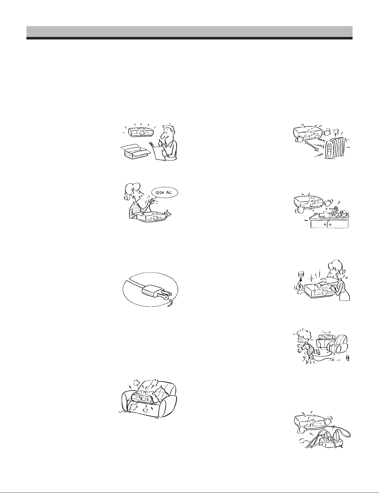
1. Read owner’s manual
After unpacking this product, read
the owner’s manual carefully, and
follow all the operating and other
instructions.
2. Power Sources
This product should be operated
only from the type of power source
indicated on the marking label. If
you are not sure of the type of
power supply to your home, consult your product dealer or local
power company. For products intended to operate from battery power, or other sources, refer
to the operating instructions.
3. Grounding or Polarization
This product may be equipped
with a polarized alternating current line plug (a plug having one
blade wider than the other). This
plug will fit into the power outlet
only one way. This is a safety
feature. If you are unable to insert
the plug fully into the outlet, try reversing the plug. If the plug
should still fail to fit, contact your electrician to replace your
obsolete outlet. Do not defeat the safety purpose of the
polarized plug.
4. Ventilation
Slots and openings in the cabinet
are provided for ventilation and to
ensure reliable operation of the
product and to protect it from overheating, and these openings must
not be blocked or covered. The
openings should never be blocked
by placing the product on a bed,
sofa, rug or other similar surface.
This product should not be placed in a built-in installation
such as a bookcase or rack unless proper ventilation is
provided or the manufacturer’s instructions have been adhered to.
5. Heat
The product should be situated
away from heat sources such as
radiators, heat registers, stoves,
or other products (including amplifiers) that produce heat.
6. Water and Moisture
Do not use this product near water - for example, near a bath tub,
wash bowl, kitchen sink, or laundry tub; in a wet basement; or
near a swimming pool and the
like.
7. Cleaning
Unplug this product from the wall
outlet before cleaning. Do not
use liquid cleaners or aerosol
cleaners. Use a damp cloth for
cleaning.
8. Power-Cord Protection
Power-supply cords should be
routed so that they are not likely
to be walked on or pinched by
items placed upon or against
them, paying particular attention
to cords at plugs, convenience
receptacles, and the point where they exit from the product.
9. Overloading
Do not overload wall outlets; extension cords, or integral
convenience receptacles as this
can result in a risk of fire or electric shock.
PREPARATION
OPERATION
RECORDING
PLAYBACK
OPERATION
NOTICE
2
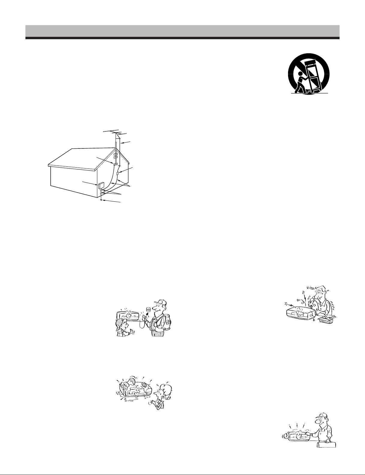
10.Outdoor Antenna Grounding
S3125A
If an outside antenna or cable system is connected to the
product, be sure the antenna or cable system is grounded so
as to provide some protection against voltage surges and
built-up static charges. Article 810 of the National Electrical
Code, ANSI/NFPA 70, provides information with regard to
proper grounding of the mast and supporting structure,
INTRODUCTION
grounding of the lead-in wire to an antenna discharge unit,
size of grounding conductors, location of antenna-discharge
unit, connection to grounding electrodes, and requirements
for the grounding electrode.
EXAMPLE OF ANTENNA GROUNDING AS PER
NATIONAL ELECTRICAL CODE
PREPARATION
S2898A
ELECTRIC
SERVICE
EQUIPMENT
NEC – NATIONAL ELECTRICAL CODE
11.Power Lines
An outside antenna system should not be located in the
vicinity of overhead power lines or other electric light or
OPERATION
RECORDING
power circuits, or where it can fall into such power lines or
circuits. When installing an outside antenna system, extreme care should be taken to keep from touching such
power lines or circuits as contact with them might be fatal.
GROUND
CLAMP
ANTENNA
LEAD IN
WIRE
ANTENNA
DISCHARGE UNIT
(NEC SECTION 810-20)
GROUNDING CONDUCTORS
(NEC SECTION 810-21)
GROUND CLAMPS
POWER SERVICE GROUNDING
ELECTRODE SYSTEM
(NEC ART 250, PART H)
15.Accessories
Do not place this product on an
unstable cart, stand, tripod,
bracket, or table. The product may
fall, causing serious injury to a
child or adult, and serious damage to the product. Use only with
a cart, stand, tripod, bracket, or
table recommended by the manufacturer, or sold with the product. Any mounting of the
product should follow the manufacturer’s instructions, and
should use a mounting accessory recommended by the
manufacturer.
A product and cart combination should be moved with care.
Quick stops, excessive force, and uneven surfaces may
cause the product and cart combination to overturn.
16.Damage Requiring Service
Unplug this product from the wall outlet and refer servicing to
qualified service personnel under the following conditions:
a) When the power-supply cord or plug is damaged.
b) If liquid has been spilled, or objects have fallen into the
product.
c) If the product has been exposed to rain or water.
d) If the product does not operate normally by following the
operating instructions. Adjust only those controls that are
covered by the operating instructions as an improper
adjustment of other controls may result in damage and
will often require extensive work by a qualified technician
to restore the product to its normal operation.
e) If the product has been dropped or damaged in any way.
f) When the product exhibits a distinct change in per-
formance - this indicates a need for service.
12.Lightning
For added protection for this product during storm, or when it is left
unattended and unused for long
periods of time, unplug it from the
wall outlet and disconnect the
antenna or cable system. This
PLAYBACK
OPERATION
will prevent damage to the product due to lightning and power-line surges.
13.Object and Liquid Entry
Never push objects of any kind
into this product through openings as they may touch dangerous
voltage points or short-out parts
that could result in a fire or electric
shock. Never spill liquid of any
NOTICE
kind on the product.
14.Attachments
Do not use attachments not recommended by the product
manufacturer as they may cause hazards.
17.Servicing
Do not attempt to service this
product yourself as opening or
removing covers may expose you
to dangerous voltage or other
hazards. Refer all servicing to
qualified service personnel.
18.Replacement Parts
When replacement parts are required, be sure the service
technician has used replacement parts specified by the
manufacturer or have the same characteristics as the original part. Unauthorized substitutions may result in fire, electric
shock, or other hazards.
19.Safety Check
Upon completion of any service
or repairs to this product, ask the
service technician to perform
safety checks to determine that
the product is in proper operating
condition.
3

INTRODUCTION
FEATURES
ii
i
Various time modes & High Density modes.
ii
With a T-120 tape, it is possible to record over periods ranging from
2 to 168 hours. Of course High Density recording is possible.
The modes are explained in more detail. (See page 21.)
ii
i
Virtual real-time recording is possible.
ii
It is possible to virtual real-time record in EPA18 mode.
(See page 21.)
ii
i
Internal time-date generator.
ii
This VCR includes an internal time-date generator, necessary for
documentation purposes. (See page 15.)
ii
i
On-screen programming.
ii
Menu driven programming simplifies set-up of various functions
including but not limited to the following:
time & date search, timer setting, and alarm recording.
ii
i
Timer recording function.
ii
With timer recording, it is possible to set two programs for each day
of the week as well as one daily program. Up to 15 programs total
are available for timer recording.
(See pages 25 - 28.)
ii
i
Tape remaining function.
ii
With this feature, it is possible to check the time remaining until the
end of tape during the recording process as well as playback
process. (See page 6, note w.)
ii
i
Alarm record function.
ii
With a dry contact closure upon the alarm input terminal, it is
possible to set the VCR into alarm mode. When recording in the
alarm mode, the VCR automatically enters into a mode which
usually is a faster recording mode. This is done so that more
information can be recorded.
ii
i
Auto record function.
ii
While in the timer record or timer standby mode, this unit can
automatically begin recording when a dry contact closure is applied
across the external control input and ground terminals.
ii
i
Alarm memory search function.
ii
This VCR provides an alarm memory function for finding the alarm
event during playback. (See page 43.)
ii
i
Repeat record function.
ii
Repeat record function enables the VCR to automatically rewind
the tape when it reaches the end and restarts the recording
process. (See page 36.)
ii
i
Restart record function.
ii
This function enables the VCR to automatically restart the recording process in the event of a power failure. After power is restored,
the VCR will restart the recording process. (See page 24.)
ii
i
Shuttle function.
ii
With the shuttle dial, a wide variety of playback functions are
available. They include picture search, slow playback, field
advance playback, reverse field advance playback, and still
playback (See pages 40 - 41.)
ii
i
Clean slow and still.
ii
A clean crisp image is crucial and is the main purpose for the
existence of a surveillance recorder. This VCR offers a clean and
noiseless playback, that is essential for surveillance applications.
(Pay attention to page 39.)
ii
i
Time date search function.
ii
With time date search, it is possible to search for a picture recorded
on a certain time and date. (See page 42.)
ii
i
Head cleaning function.
ii
Head cleaning is automatically performed at the end of timer
recording and at tape end in order to prevent head jamming. There
is also head cleaning once every two hours when operating in time
modes of 24 hours or more.
ii
i
Automatic head clog detection.
ii
When recording in time mode SP120 and SP168, video head clog
detection is automatically carried out once for every two hours.
When the video head clog is found, head cleaning is carried out for
approximately 10 times. When cleaning is still not possible, "E-6" is
displayed.
ii
i
Record check function.
ii
By pressing the record check button during recording, the VCR
automatically replays the last few seconds of the recording. (See
page 5, note 2).
ii
i
Wired remote control function (Option)
ii
The wired remote control allows the following VCR functions.
• Fast Forward • Forward picture search
• Rewind • Reverse picture search
• Pause • Still
• Field advance (forward, reverse)
• Play • Stop
• Play back time
INTRODUCTION
PREPARATION
OPERATION
RECORDING
TABLE OF CONTENTS
PLEASE READ ..................................................................................................1
IMPORTANT PRECAUTIONS ...........................................................................1
IMPORTANT SAFETY INSTRUCTIONS ..................................................... 2 ~ 3
INTRODUCTION ....................................................................................... 4 ~ 10
FEATURES................................................................................................. 4
TABLE OF CONTENTS.............................................................................. 4
INSTRUCTIONS IN BRIEF......................................................................... 5
VCR DISPLAY ............................................................................................9
WIRED REMOTE CONTROL (Option) ..................................................... 10
PREPARATION .......................................................................................11 ~ 22
CONNECTIONS .......................................................................................11
CONTENTS OF SCREEN DISPLAY........................................................ 13
SETTING THE CLOCK.............................................................................15
ON-SCREEN FUNCTIONS ......................................................................16
DISPLAY SCREEN ..................................................................................17
COUNTER DISPLAYS ............................................................................. 19
SETTING THE RECORDING/PLAYBACK TIME ..................................... 21
LOADING AND UNLOADING A VIDEO CASSETTE ...............................22
RECORDING OPERATION .....................................................................23 ~ 38
RECORDING ............................................................................................ 23
RESTART RECORDING ..........................................................................24
TIMER RECORDING................................................................................25
ALARM RECORDING .............................................................................. 29
AUTO RECORDING ................................................................................. 32
OPERATION AFTER TAPE END DETECTION .......................................34
HOW TO SET TO AUTO REWIND AT END OF TAPE ......................35
HOW TO SET TO REPEAT RECORD AT END OF TAPE ................ 36
RECORDING WITH THE SEQUENTIAL SWITCHER ............................. 37
PLAYBACK OPERATION ........................................................................ 39 ~ 43
PLAYBACK............................................................................................... 39
PLAYBACK IN VARIOUS MODES........................................................... 41
TIME DATE SEARCH...............................................................................42
ALARM SEARCH ..................................................................................... 43
NOTICE ..................................................................................................44 ~ 50
SIGNAL LEVELS OF INPUT/OUTPUT TERMINALS............................... 44
DAILY AND PERIODIC INSPECTION ..................................................... 45
CAUTIONS DURING USE........................................................................ 47
BEFORE CALLING SERVICE PERSONNEL ..........................................48
SPECIFICATIONS.................................................................................... 50
PLAYBACK
NOTICE
4
OPERATION
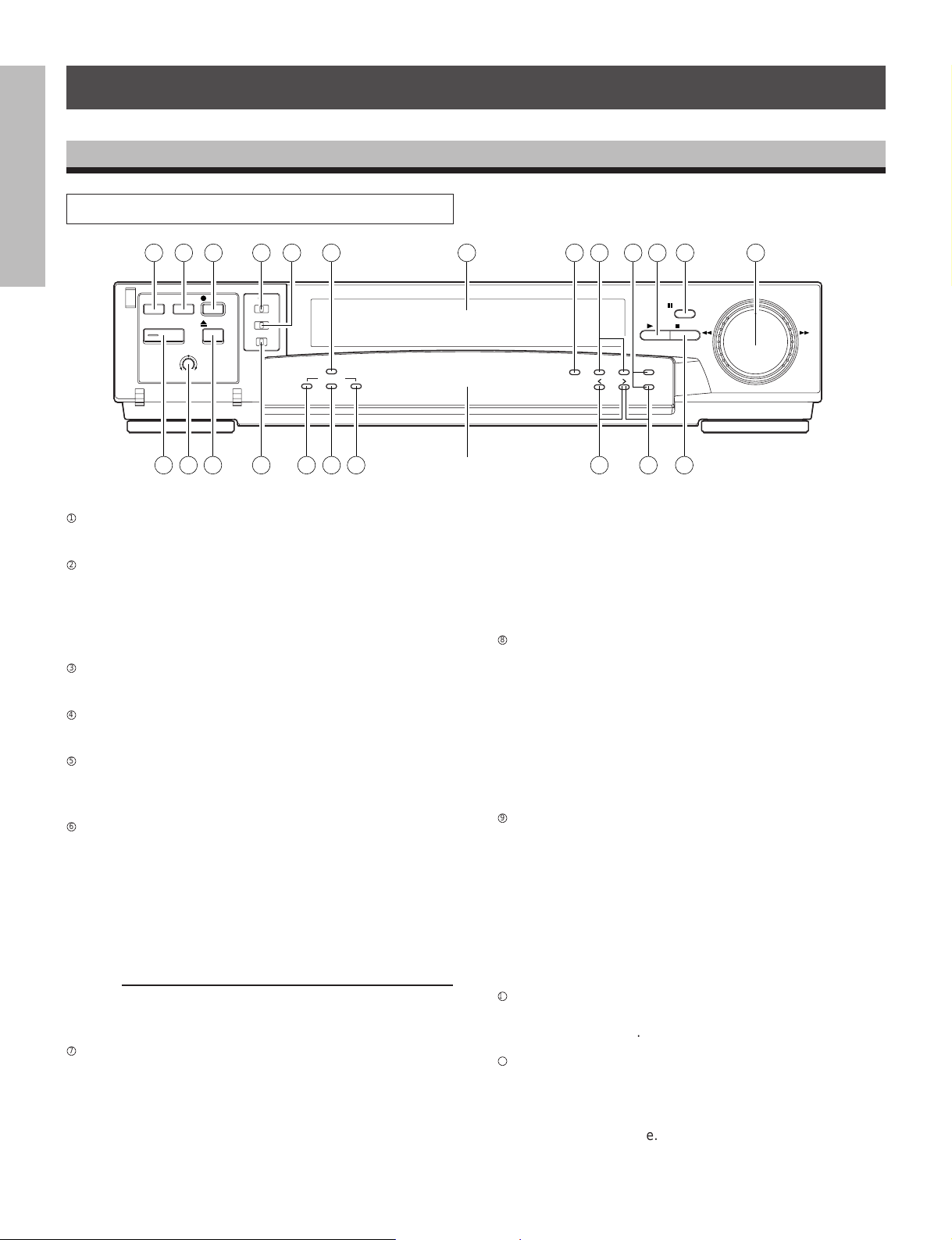
INSTRUCTIONS IN BRIEF
Front Panel
INTRODUCTION
2 3 4
REC CHECK
TIMER
POWER
PICTURE
SOFT
SHARP
REC
EJECT
6 7
VIDEO MODE
COLOR
AUTO B/W
REMOTE
OFF REMOTE OPTION
BUZZER
ON OFF
12 13 14 19 21 2216 18
TIME LAPSE VCR
4Head 168Hour
TAPE REMAIN
COUNTER
ALARM RESETMEMORY
DISPLAY
TIME MODE
–
SET
SHIFT
+
TRACKING
LOCATION SELECT
PAUSE/STILL
PLAY
STOP REV FWD
PREPARATION
POWER button
1
1 5
23
9 10 118
Press to turn the power ON and OFF.
REC CHECK button
2
Press this button while in record mode to check the picture
that was just recorded. After an approximate 2 second
playback the VCR automatically goes back into record
mode.
OPERATION
RECORDING
TIMER button
3
Press this button to set the VCR in timer recording mode.
REC button
4
Press to set the VCR in record mode.
EJECT button
5
Press to eject the cassette automatically from the cassette
compartment.
VIDEO MODE switch
6
In the event of a weak color signal or insufficient S/N ratio,
set this switch to the appropriate setting (color or B/W).
PLAYBACK
OPERATION
AUTO : Automatically switches the circuit according
to the input signal or playback signal.
COLOR : Forcibly switches the circuit to color mode.
B / W : Forcibly switches the circuit to black and
white mode.
Note:
Regardless of what position the VIDEO MODE switch is in,
the EE output signal is the same as the input signal.
REMOTE switch (mode lock)
7
NOTICE
OFF : Set for normal operation.
REMOTE : Set for use with optional module connected
onto rear panel. This will lock the front
panel. Set switch to this position for mode
lock.
VCR DISPLAY
15 17 20
OPTION : Set for external operations when you use an
option module connected onto rear panel.
When switch is set to this position, the front
panel will be operationally limited. (See the
Instruction Manual supplied with the optional
module.)
BUZZER switch
8
This is the on/off switch for the buzzer. The buzzer sounds
continually when dew condensation is detected, when the
VCR starts alarm recording, and when recording reaches
to tape end. The buzzer beeps five times with a recordprotected cassette being inserted when REC button or
TIMER button is pressed.
The buzzer sound may be cancelled by setting this switch
off.
COUNTER MEMORY button
9
• Press once to set “COUNT. M” (counter memory) on the
VCR DISPLAY. The tape stops at a count of “0000” in
fast-forward mode or rewind mode.
• Press twice to set “ALARM M” (alarm memory) on the
VCR DISPLAY. The tape stops automatically at the first
alarm event detected in fast-forward mode or rewind
mode. Then the VCR is set to playback after still mode.
• Press three times to cancel this function.
COUNTER ALARM button
p
Press to display the tape counter or the alarm counter on
the VCR DISPLAY.
COUNTER RESET button
q
• Press to reset the tape counter to “0000” while in the
tape counter mode.
• Press to reset the alarm counter to “A-00” while in the
alarm counter mode.
5

TAPE REMAIN button
w
The approximate time remaining on the tape is displayed
on the counter (in a 2 hour scale using a T-120 tape) while
this button is being pressed.
CASSETTE COMPARTMENT
e
Insert a cassette into this compartment to load the tape.
DISPLAY button
r
Press to display the MENU screen and change the
settings.
SHIFT / button
t
Press to select a desired menu on the screen.
TIME MODE / SET + – buttons
y
• Press either of the buttons to set the recording time
mode and playback time mode.
• Press either the + or the – button to set the mode and
the numerical value for each menu on the screen.
LOCATION SELECT button /
u
Press to change the position of superimposed characters
on the screen.
TRACKING buttons ( / )
i
Adjust to eliminate noise from playback picture.
PLAY button
o
Press to start the playback mode.
STOP button
;
Press to stop tape running.
PAUSE/STILL button
a
• Press during recording to pause recording.
• Press during playback for a still picture.
SHUTTLE dial
s
Turn this dial clockwise and hold:
• To fast forward the tape during the stop mode.
• To operate the forward picture search during the playback.
• To operate the forward slow play during the still mode.
Turn this dial counter clockwise and hold:
• To rewind the tape during the stop mode.
• To operate the reverse picture search during the playback.
• To operate the reverse slow play during the still mode.
PICTURE control
d
Adjust to soften or sharpen the picture during playback.
INTRODUCTION
PREPARATION
OPERATION
RECORDING
PLAYBACK
OPERATION
NOTICE
6
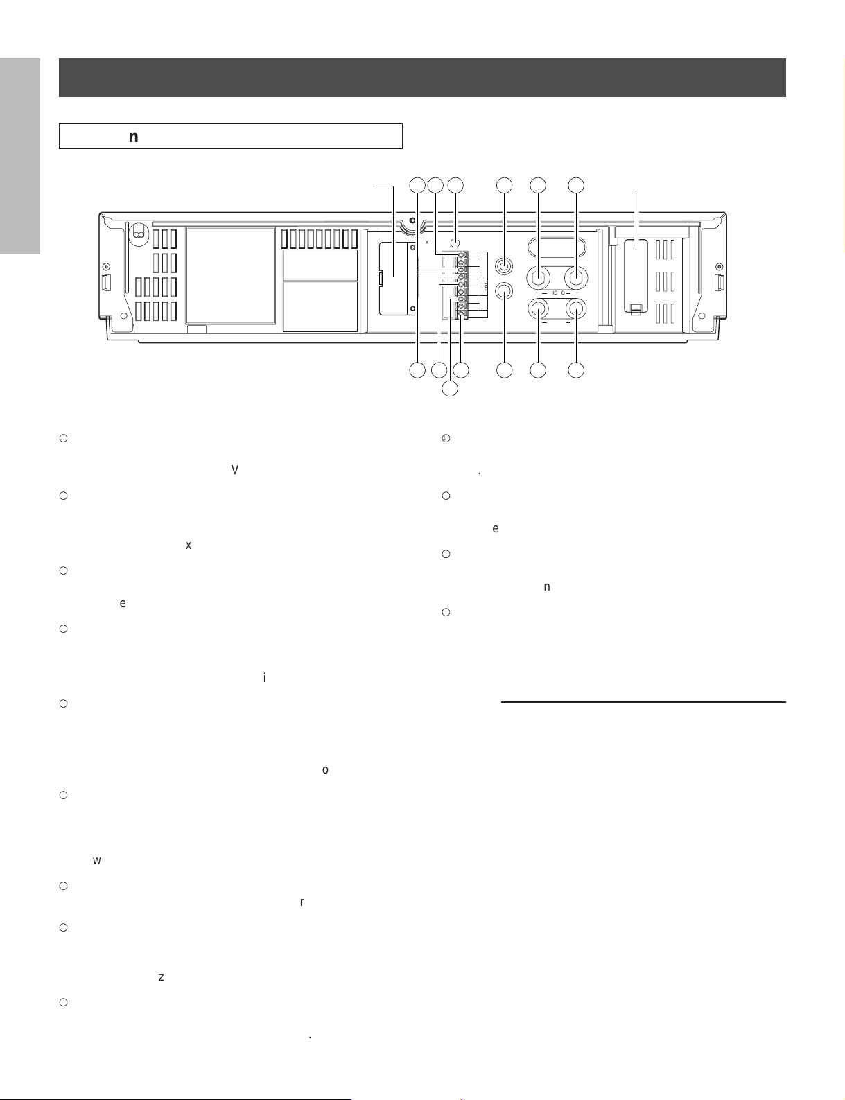
Rear Panel
INTRODUCTION
PREPARATION
TAPE END OUT terminal
1
Signal output terminal to annunciate to other devices that
the tape has run out on the VCR.
REC TRIGGER OUT terminal
2
Signal output terminal to control the switching interval of
the video cameras when connected to a sequential
switcher or multiplexer.
ALARM OUT terminal
3
OPERATION
RECORDING
Output terminal to transmit an alarm signal to peripheral
equipment.
ALARM RESET terminal
4
Input terminal to reset alarm recording.
Alarm recording is reset when this terminal is connected to
the ground terminal during recording.
OPTION BOX cover
SEE MANUAL
109
OUT
VIDEO
IN
OUT
AUDIO
IN
SEE MANUAL
1211
ALL CLEAR
7654 BATTERY cover
REMOTE IN
IN
GND
RESET
ALARM
OUT
MIC IN
IN
GND
EXT
CONT.
OUT
GND
REC
TRIGG.
TAPE END
81133
2
VIDEO OUT connector (BNC)
p
Output connector for video signal. Connect with a monitor
TV.
AUDIO IN jack (RCA type)
q
Input jack for audio signal. Connect with an external audio
source.
AUDIO OUT jack (RCA type)
w
Output jack for audio signal. Connect with an external
audio equipment.
EXTERNAL CONTROL IN terminal
e
Automatic recording is performed when this terminal is
connected to the signal ground while in the timer mode
(timer recording or timer standby).
ALARM IN terminal
5
Input terminal to start alarm recording.
The VCR goes into alarm recording mode when this
terminal is connected to the ground terminal while in the
record mode, record pause mode, or stop mode.
PLAYBACK
OPERATION
ALL CLEAR button
6
Pressing this button will clear the entire time-date, and
timer program memory. The power will be turned off at the
same time. Pressing the POWER button will restore
power.
REMOTE IN jack
7
Input jack for optional wired remote control.
MIC IN jack
8
Input jack for audio signals from a microphone. The RCA
NOTICE
jack input (audio input) is automatically switched off when
this jack is utilized.
VIDEO IN connector (BNC)
9
Input connector for video signal. Connect with an external
video source such as a video camera, etc.
7
Notes:
• ALL CLEAR button
Do not use this function (ALL CLEAR) frequently.
Press this button only when an abnormality (ex. VCR
display does not turn ON.) occurs.
When this button is pressed, the power turns OFF and
each data stored (ex. clock, timer program, etc.) is cleared
and returns to the initial setting status. It will be necessary
to re-program the VCR after turning the unit on again.
• OPTION BOX cover
This VCR provides an optional port for connecting an
optional module to the rear of the unit.
If you would like additional information regarding the
available options for this VCR please consult your dealer.
The installation of the optional module should be performed only by qualified technical personnel.
A Word on the Exclusive 3N-100AAS
Battery Pack
The nickel-cadmium battery pack (3N-100AAS) is used for
power source of the built-in clock and memory circuit.
Charging the Battery Pack
1. Turn on the power of the VCR.
2. The battery pack in the VCR is charged.
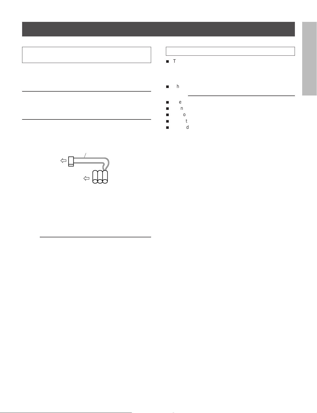
Battery Installation
Removal:
1. Remove the battery cover.
2. Disconnect the connector in the VCR.
Specification of Battery
i
Temperature
For charging : 0°C to 80°C
For operating : –20°C to 80°C
For storing : –30°C to 80°C
i
Charging time : more than 48 hours
Notes:
i
Use only for this VCR.
i
Do not dispose of the batteries into fire.
i
Do not short circuit the terminals.
i
Do not modify or disassemble.
i
Avoid dropping, unnecessary shocks.
INTRODUCTION
RED wire
Connector
Battery pack
Installation:
1. Install the battery pack placing the red wire upside, and
connect the connector on the battery pack to this VCR.
Make sure the polarities (+) and (–) are correct.
2. Close the battery cover.
Note:
If the Battery Pack is removed, the memory data will be
erased. In such a case, perform the setting from the first step.
PREPARATION
OPERATION
RECORDING
PLAYBACK
OPERATION
8
NOTICE
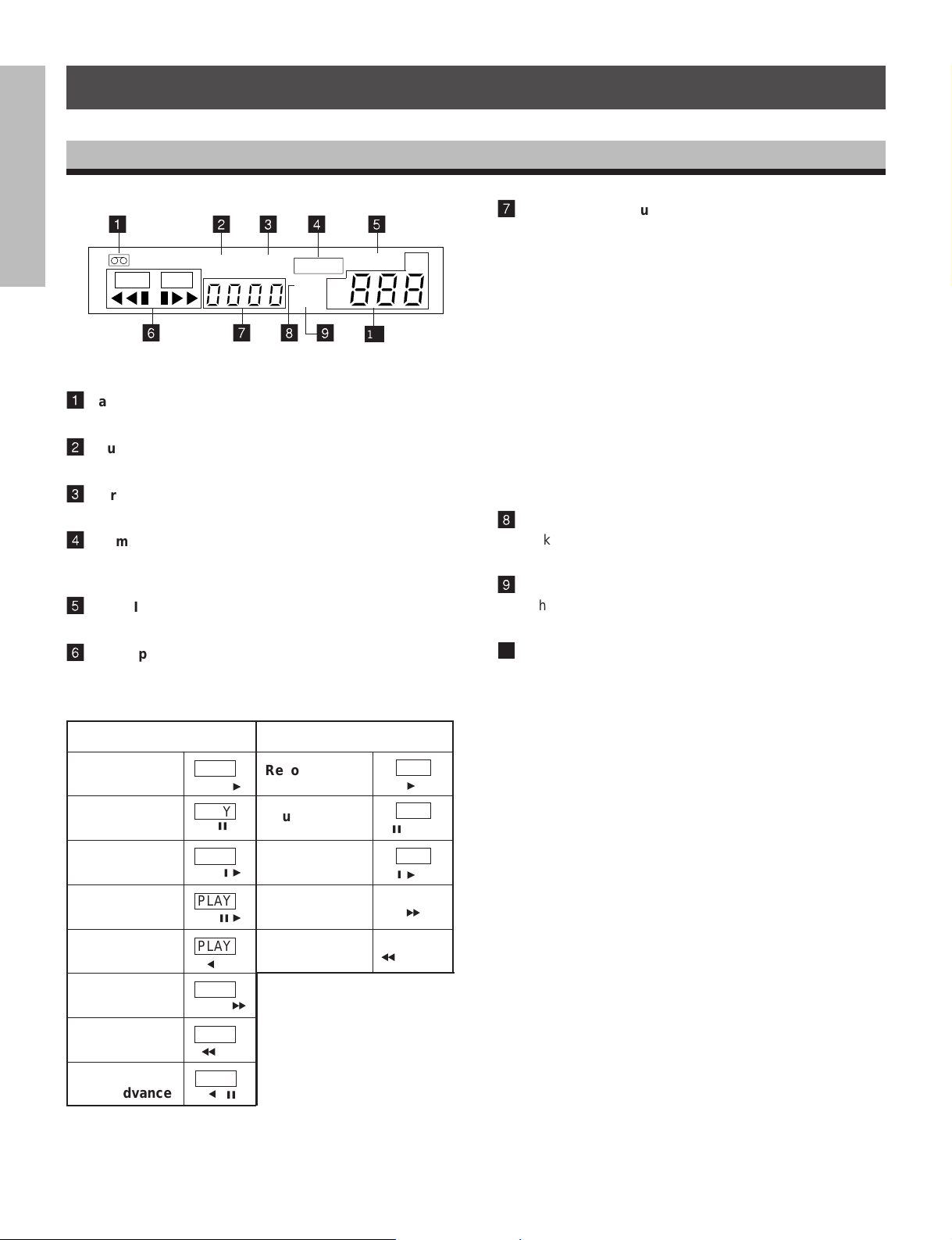
VCR DISPLAY
INTRODUCTION
PREPARATION
OPERATION
RECORDING
1
PLAY REC
1
Cassette indicator
Lights when a tape is inserted.
2
Counter memory indicator
Lights when the counter memory is selected.
3
Alarm Memory indicator
Lights when the alarm memory is selected.
4
Alarm indicator
Lights during alarm recording and blinks after an alarm
recording cycle is completed.
5
PW.FAIL (Power Failure) indicator
Blinks when a power failure occurs.
6
TAPE operation indicator
Displays as shown below, depending on operational
modes.
6
2 3 4 5
COUNT.MALARM
78
ALARM
M
DEW
SP
TIMER
EP
9
PW.FAIL
10
7
Counter/Alarm Counter/Remaining Tape/Error Message indicator
H
• Press the ALARM button to display the alarm counter.
• Press the ALARM button again to return to display the
counter.
• Press the TAPE REMAIN button to display the remaining
tape time.
• When an abnormality occurs during operation, the error
code is displayed.
E-1: Abnormality on reel rotation during tape running.
E-3: Abnormality on cylinder rotation during recording
and playback.
E-4: Abnormality on tape loading mechanism.
E-5: Video tape is cut.
E-6: Head clog.
E-8: Dew condensation.
8
Dew indicator
Blinks when the dew condensation has developed inside
the VCR.
9
Timer indicator
Lights when the timer recording button is pressed and the
VCR has been set in timer record mode.
10
Record/Playback Time indicator
Displays record/playback time mode.
Playback
Still
Slow
PLAYBACK
OPERATION
Field Advance
Reverse
Playback
Forward
Picture Search
Reverse
Picture Search
Reverse
NOTICE
Field Advance
Playback
PLAY
PLAY
j
PLAY
j
PLAY
jy
PLAY
a
PLAY
PLAY
b
PLAY
a
y
y
e
j
Other than playback
Record
Pause
Time-lapse
Fast Forward
Rewind
b
REC
REC
j
REC
j
y
y
e
9
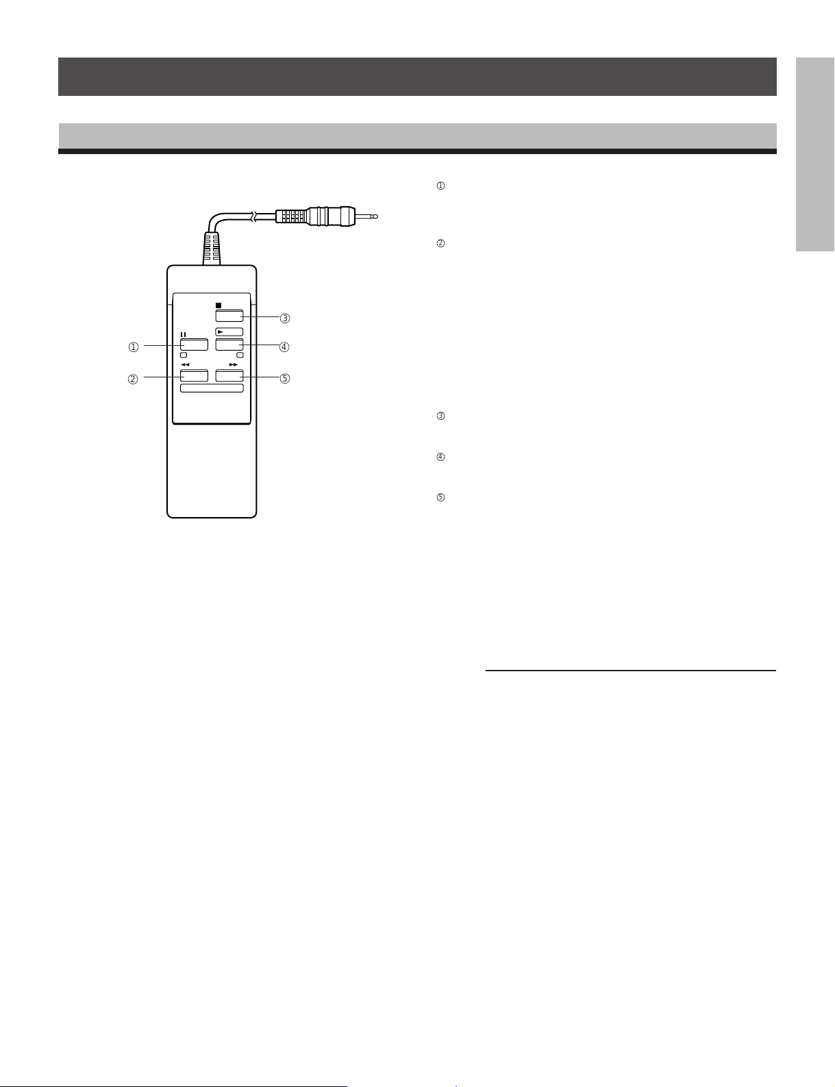
WIRED REMOTE CONTROL (Option)
PAUSE/STILL button
1
• Press during recording to pause the recording.
• Press during playback to play back a still picture.
REW button
2
• Press to rewind the tape.
• Press during playback for reverse picture search.
STOP
2
1
PAUSE/
PLAY
STILL
PICTURE
SEARCH
REW FF
(±) PLAY TIME (+)
3
4
5
• Press the REW button while pressing the PLAY button,
• Each time pressing the REW button during still playback
STOP button
3
Press to stop tape running.
PLAY button
4
Press to start play back.
FF button
5
• Press to fast forward mode.
• Press during playback for forward picture search mode.
• Press the FF button while pressing the PLAY button, the
• Each time pressing the FF button during still playback
To release the reverse picture search mode, press the
PLAY button.
the time mode can be selected.
mode, the Reverse Field Advance playback (one field)
will be carried out.
To release the forward picture search mode, press the
PLAY button.
Time mode can be selected.
mode, the Field Advance playback (one field) will be
carried out.
INTRODUCTION
PREPARATION
OPERATION
RECORDING
Note:
If you wish to obtain the wired remote control, please consult
your dealer.
PLAYBACK
NOTICE
10
OPERATION
PREPARATION
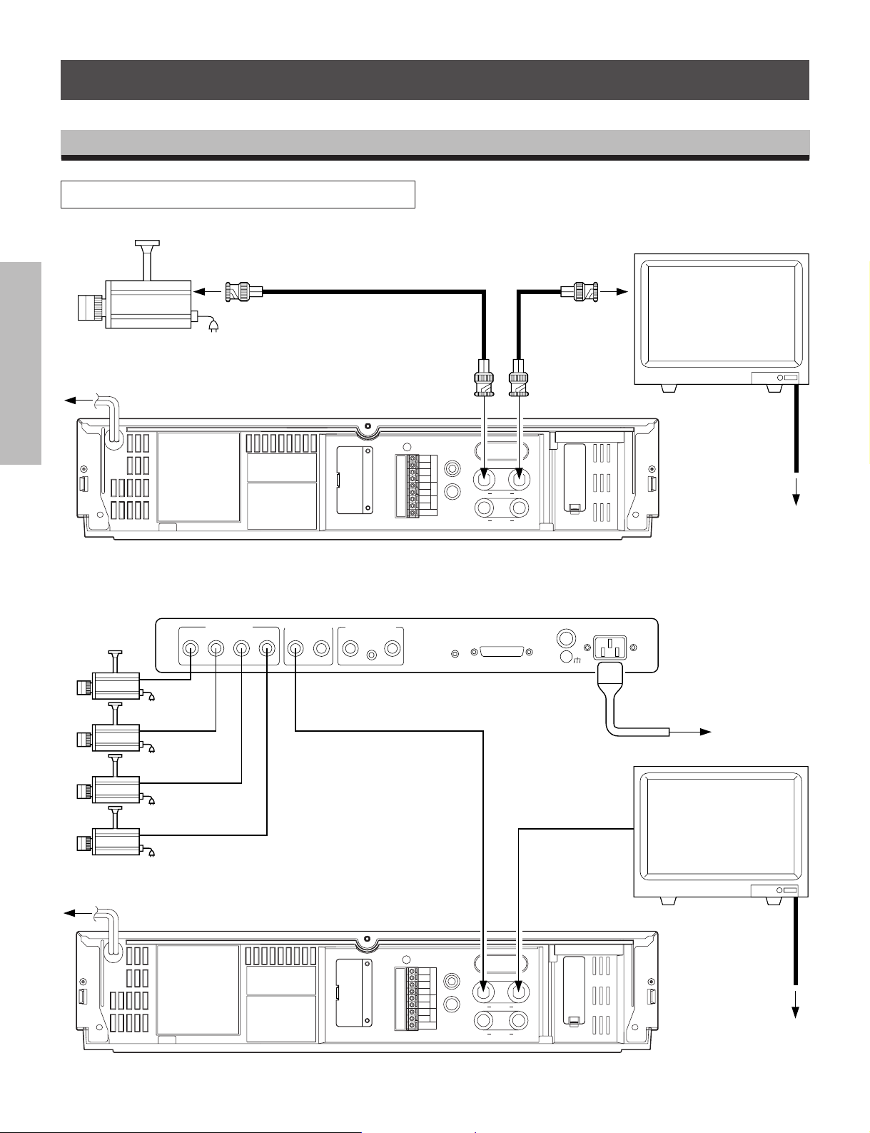
CONNECTIONS
Connection with a Video Camera
INTRODUCTION
To VIDEO OUT (BNC connector)
camera
Monitor TV
To VIDEO IN
(BNC connector)
RG/59u coaxial
cable.
To AC OUTLET
(120V)
PREPARATION
OPERATION
RECORDING
Quadrant picture unit
VIDEO INPUT
1234
SWITCHED
EXT. REF INPUT
IN
VIDEO OUTPUT
QUAD
ONLY
To QUAD. OUT
To VIDEO IN
(BNC connector)
75Ω
ON
OFF
ALL CLEAR
LOOP
THROUGH
IN
GND
RESET
OUT
IN
GND
OUT
GND
TAPE END
ALARM
EXT
REC
REMOTE IN
CONT.
TRIGG.
MIC IN
FRONT
PANEL
DISABLE
ENABLE
IN
IN
VIDEO
AUDIO
REMOTE
To VIDEO OUT
(BNC connector)
OUT
FUSE
1A
125V
SEE MANUALSEE MANUAL
OUT
To AC OUTLET
(120V)
AC IN
To AC OUTLET
(120V)
Monitor TV
PLAYBACK
OPERATION
To AC OUTLET
(120V)
NOTICE
11
To VIDEO IN
To VIDEO IN To VIDEO OUT
ALL CLEAR
IN
GND
RESET
OUT
IN
GND
OUT
GND
TAPE END
ALARM
EXT
REC
REMOTE IN
CONT.
TRIGG.
MIC IN
VIDEO
OUT
IN
OUT
AUDIO
IN
SEE MANUALSEE MANUAL
To AC OUTLET
(120V)
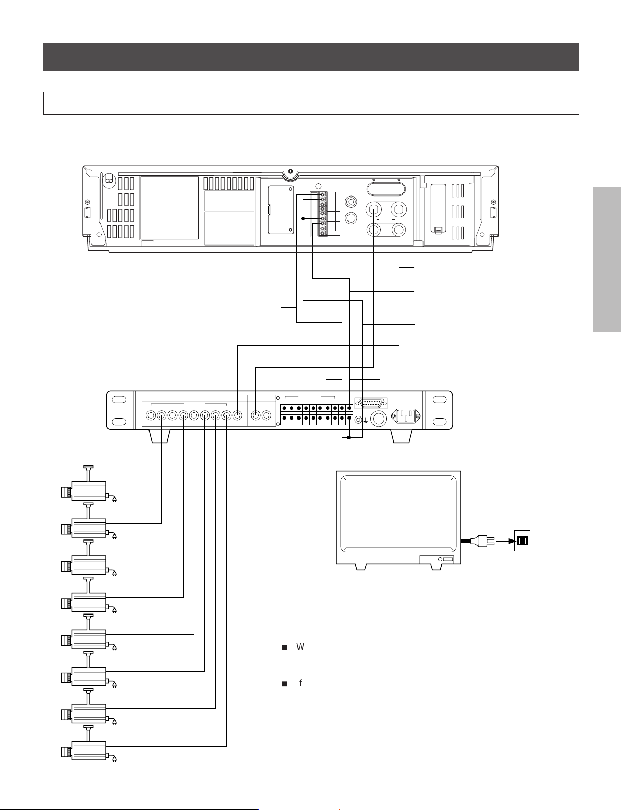
Typical Connection with the Sequential Switcher
When connected with a sequential switcher, set the alarm recording mode to MANUAL by menu screen.
For further details, consult the instruction manuals of the connected devices.
INTRODUCTION
Frame Sequential Switcher
To VCR playback
To VCR REC
VIDEO IN VIDEO OUT
12345
CAMERA
678
To ALARM IN
VCR
VCR
MONITOR
REC
PLAY
ALL CLEAR
SEE MANUAL
To ALARM
OUTPUT
ALARM IN
12345678
REMOTE IN
IN
GND
RESET
ALARM
OUT
MIC IN
IN
EXT
CONT.
GND
OUT
GND
REC
TRIGG.
TAPE END
To
VIDEO IN
ALARM
OUT
VIDEO
OUT
IN
AUDIO
OUT
IN
SEE MANUAL
To VIDEO OUT
To REC TRIGG. OUT
To GND
To REC TRIGGER INPUT
REMOTE
Monitor TV.
PREPARATION
OPERATION
RECORDING
AC120V
To AC outlet
When using the VCR connected to a frame sequential switcher, pay
attention to the following matters.
i
When playing back in the
SPA12, EPA18 or SPA24 mode, mixing of
pictures from other channels may occur. If this occurs, play back in a
mode other than the
i
If the following phenomena occur during playback in a time mode of
SPA12, EPA18 or SPA24 mode.
24 hours or longer, adjust by using the TRACKING button.
1. Mixing of signals from another channel.
Go to slow playback and press the TRACKING button to adjust
until the picture appears from the channel you want to view.
2. Picture waves up and down.
Press the TRACKING button during still picture playback and
adjust the picture until the picture stops waving up and down.
PLAYBACK
NOTICE
12
OPERATION
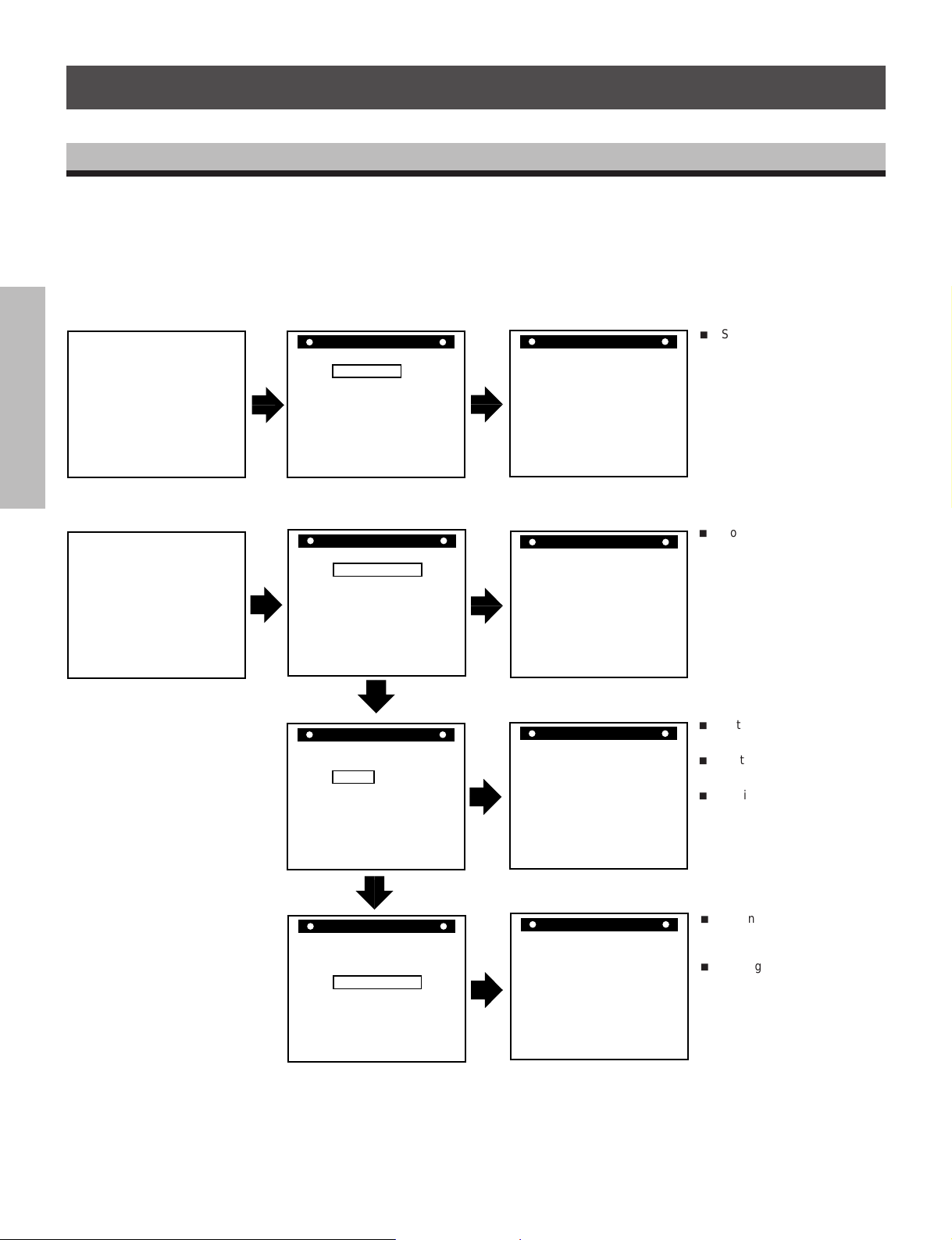
CONTENTS OF SCREEN DISPLAY
RESTART REC OFF
TAPE END MODE STOP
ALARM STOP
S E T U P
ALARM REC TIME 15S
MENU=[DISPLAY]
SPEED A 2
SP
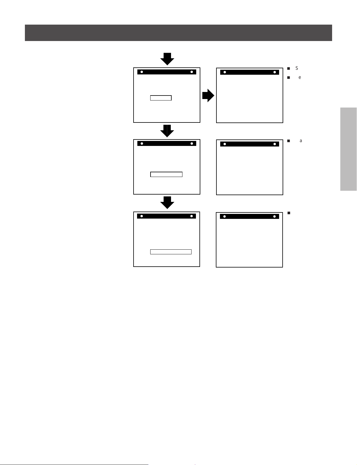
The normal MENU screen provides six menus after the initial screen for clock setting. Each MENU screen is shown below.
Press the DISPLAY button for a MENU screen. The menu is selected by pressing the SHIFT button. Then press the SET button to
INTRODUCTION
proceed to the next screen. Use the SHIFT button and the SET button for settings and adjustments in the same manner. To return
to the initial screen press the DISPLAY button.
Monitor Screen (initial screen)
PREPARATION
Monitor Screen (normal screen)
OPERATION
RECORDING
PLAYBACK
OPERATION
1/ 1/97 WED
0:00:00 A 2
SP
8/28/97 THU
17:30:02 A 2
SP
MENU Screen (initial screen)
M E N U
CLOCK SET
SETUPSETUP
DISPLAY MODE
TIME DATE SEARCH
END=[DISPLAY]
MENU Screen (normal screen)
M E N U
CLOCK ADJUST
SETUPSETUP
DISPLAY MODE
PROGRAM
ALARM RECALL
TIME DATE SEARCH
END=[DISPLAY]
M E N U
CLOCK ADJUST
SETUP
DISPLAY MODE
PROGRAM
ALARM RECALL
TIME DATE SEARCH
END=[DISPLAY]
M E N U
CLOCK ADJUST
SETUPSETUP
DISPLAY MODE
PROGRAM
ALARM RECALL
TIME DATE SEARCH
END=[DISPLAY]
CLOCK SET Screen
CLOCK SET
(DAYLIGHT
SAVING TIME) OUT
(MONTH) (DAY) (YEAR)
1 / 1 / '97
WED
0:00(TIME)
MENU=[DISPLAY]
CLOCK ADJUST Screen
CLOCK ADJUST
(DAYLIGHT
SAVING TIME) IN
(MONTH) (DAY) (YEAR)
8 / 28 / '97
THU
17:30(TIME)
MENU=[DISPLAY]
SETUP Screen
DISPLAY Screen
DISPLAY
(DATE) ON
(DAY OF THE WEEK) ON
(TIME) ON
(SPEED) ON
(VCR) OFF
(ALARM) ON
(12H/24H) 24H
(CHAR.LINES) 6
MENU=[DISPLAY]
Comment
i
Setting of clock.
Unless the date-time is
adjusted, the “PROGRAM”
and “ALARM RECALL” will
not appear on the MENU
screen.
i
Correction of date-time.
i
Setting of alarm recording
mode (recording time,
recording mode)
i
Setting of recording for
restoration of power following
a power failure.
i
Setting of operation after
detection of tape end (tape
end detection mode for tape
end detection during
recording and when an alarm
recording is made).
i
Setting of display screen
(date, day of week, time,
recording time, VCR number,
alarm).
i
Setting of time display (24H,
12H).
NOTICE
13
M E N U
TH2 ON --:-- --:-- 120
WE2 ON --:-- --:-- 120
WE1 ON --:-- --:-- 120
TU2 ON --:-- --:-- 120
TU1 ON --:-- --:-- 120
TH1 ON --:-- --:-- 120
PROGRAM
MO1 ON --:-- --:-- 120
MENU=[DISPLAY]
MO2 ON --:-- --:-- 120
➜
➜
➜
➜
➜
➜
➜
➜
SP
SP
SP
SP
SP
SP
SP
SP
CLOCK ADJUST
SETUPSETUP
DISPLAY MODE
PROGRAM
ALARM RECALL
TIME DATE SEARCH
END=[DISPLAY]
PROGRAM Screen
i
Setting of timer
recording.
i
Setting of auto
recording.
INTRODUCTION
M E N U
CLOCK ADJUST
SETUPSETUP
DISPLAY MODE
PROGRAM
ALARM RECALL
TIME DATE SEARCH
END=[DISPLAY]
M E N U
CLOCK ADJUST
SETUPSETUP
DISPLAY MODE
PROGRAM
ALARM RECALL
TIME DATE SEARCH
END=[DISPLAY]
ALARM RECALL Screen
ALARM RECALL
AL1 --/--/----- --:--:-AL2 --/--/----- --:--:-AL3 --/--/----- --:--:-AL4 --/--/----- --:--:-AL5 --/--/----- --:--:-AL6 --/--/----- --:--:-AL7 --/--/----- --:--:-1ST --/--/----- --:--:--
MENU=[DISPLAY]
TIME DATE SEARCH Screen
TIME DATE SEARCH
DAY 01
HOUR 00
MINUTE 00
SEARCH FORWARD
REVERSE
MENU=[DISPLAY]
i
Alarm recall
display
i
Set the day and
time to be
searched and
searching
direction.
PREPARATION
OPERATION
RECORDING
PLAYBACK
NOTICE
14
OPERATION
DISPLAY
TIME MODE
SET
SHIFT
TRACKING
LOCATION SELECT
+–
SETTING THE CLOCK
M E N U
CLOCK ADJUST
SETUPSETUP
DISPLAY MODE
END=[DISPLAY]
PROGRAM
ALARM RECALL
TIME DATE SEARCH
DISPLAY
TIME MODE
SET
SHIFT
TRACKING
LOCATION SELECT
+–
DISPLAY
TIME MODE
SET
SHIFT
TRACKING
LOCATION SELECT
+–
CLOCK SET
MENU=[DISPLAY]
(MONTH) (DAY) (YEAR)
8 / 28 / '97
THU
1:00(TIME)
(DAYLIGHT
SAVING TIME) IN
CLOCK SET
MENU=[DISPLAY]
(MONTH) (DAY) (YEAR)
8 / 28 / '97
THU
17:00(TIME)
(DAYLIGHT
SAVING TIME) IN
CLOCK SET
MENU=[DISPLAY]
(MONTH) (DAY) (YEAR)
8 / 28 / '97
THU
17:30(TIME) 17
(DAYLIGHT
SAVING TIME) IN
17:30:02 A 2
8/28/97 THU
SP
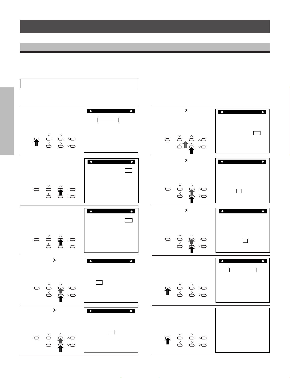
An internal clock generates time and date for superimposing on the monitor screen. Adjust the time from the MENU screen (initial
screen). After the clock is set, the data and time modes are displayed on the monitor screen (live picture).
INTRODUCTION
Operation
In case of setting to 5:30 PM, Thursday, August 28, 1997;
Press the DISPLAY
button.
1
PREPARATION
DISPLAY
Press the + SET button.
2
DISPLAY
OPERATION
RECORDING
Press the + SET button
and set the DAYLIGHT
3
SAVING TIME to IN.
DISPLAY
TIME MODE
SET
SHIFT
TIME MODE
SET
SHIFT
TIME MODE
SET
SHIFT
+–
TRACKING
LOCATION SELECT
+–
TRACKING
LOCATION SELECT
+–
TRACKING
LOCATION SELECT
M E N U
CLOCK SET
SETUPSETUP
DISPLAY MODE
TIME DATE SEARCH
END=[DISPLAY]
CLOCK SET
(DAYLIGHT
SAVING TIME) OUT
(MONTH) (DAY) (YEAR)
1 / 1 / '97
WED
0:00(TIME)
MENU=[DISPLAY]
CLOCK ADJUST
(DAYLIGHT
SAVING TIME) IN
(MONTH) (DAY) (YEAR)
1 / 1 / '97
WED
1:00(TIME)
MENU=[DISPLAY]
Press the SHIFT
button to blink Year and
6
press the + or – SET
button to set to “97”.
Press the SHIFT
button to blink Time in
7
hours and press the +
SET button to set to “17”.
Press the SHIFT
button to blink Time in
8
minutes and press the +
SET button to set to “30”.
DISPLAY
TIME MODE
+–
SET
SHIFT
LOCATION SELECT
TRACKING
4
PLAYBACK
OPERATION
5
NOTICE
15
Press the SHIFT
button to blink Month
and press the + SET
button to set to “8”.
DISPLAY
TIME MODE
SET
SHIFT
LOCATION SELECT
+–
Press the SHIFT
button to blink Day and
press the + SET button
to set to “28”.
TIME MODE
SET
SHIFT
+–
LOCATION SELECT
DISPLAY
TRACKING
TRACKING
CLOCK SET
(DAYLIGHT
SAVING TIME) IN
(MONTH) (DAY) (YEAR)
8 / 1 / '97
FRI
1:00(TIME)
MENU=[DISPLAY]
CLOCK SET
(DAYLIGHT
SAVING TIME) IN
(MONTH) (DAY) (YEAR)
8 / 28 / '97
THU
1:00(TIME)
MENU=[DISPLAY]
Press the DISPLAY
button to start display of
9
the set date and time.
Press the DISPLAY
button to return to the
10
normal screen.
DISPLAY
TIME MODE
SET
SHIFT
LOCATION SELECT
+–
TRACKING

ON-SCREEN FUNCTIONS
When the power is turned ON, the time and date modes are displayed on the monitor screen (live picture). On-screen displays are
not available in the event of no video input signal.
Date-Time Display
VCR display
Date1 Day of the week2
8/28/97 THU
INTRODUCTION
8/28/97 THU
17:30:02 A 2
Monitor screen
Date : Displayed with the month-day-year.
1
Day of the week :Automatically set to the correct day of the week when the date is set.
2
Time : Set to 24-hour cycle at factory.
3
It is possible to modify to 12-hour (AM/PM) cycle display.
Playback/Recording Time : Playback or Recording time display
4
SP
17:30:02 A 2
On-Screen Position
Press the LOCATION SELECT button to adjust the display to desirable position.
The display moves in the direction shown by the arrows.
LOCATION SELECT
However, during the date-time display screen, pay attention to the following when
setting the date and time display positions:
When the display is set to an end of the monitor screen as shown in the figure,
synchronization instability or color flickering may occur in some monitor TVs.
Press this button : To down
Press this button : To right
8/28/97 THU
17:30:02 A 2
17:30:02 A 2
8/28/97 THU
17:30:02 A 2
SP
8/28/97 THU
17:30:02 A 2
8/28/97 THU
17:30:02 A 2
SPSP
SP
SP
SP
Time3
4
Playback/Recording time
SP : SP mode
Nothing : EP mode
PREPARATION
OPERATION
RECORDING
PLAYBACK
OPERATION
16
NOTICE

17:30:02 A 2
8/28/97 THU
SP
DISPLAY SCREEN
Set the MENU screen to DISPLAY screen, and select or set each item.
Before operation, set the MENU screen to DISPLAY screen (See page 13.).
INTRODUCTION
Note:
Press the DISPLAY button twice to return from the display screen to the monitor screen.
Operation Display Screen Monitor Screen
Erasing the date display.
Press the
+ or – SET button to go to OFF.
DISPLAY
PREPARATION
Erasing the day of the week display.
Press the
and press the + or – SET button to go to OFF.
DISPLAY
OPERATION
RECORDING
Erasing the time display.
Press the
+ or – SET button to go to OFF.
DISPLAY
or SHIFT button to blink DATE and press the
TIME MODE
SET
SHIFT
+–
TRACKING
LOCATION SELECT
Changes between OFF and ON
each time the + or – SET button
is pressed.
or SHIFT button to blink DAY OF THE WEEK
TIME MODE
SET
SHIFT
+–
TRACKING
LOCATION SELECT
Changes between OFF and ON
each time the SET button is
pressed.
or SHIFT button to blink TIME and press the
TIME MODE
SET
SHIFT
LOCATION SELECT
+–
TRACKING
Changes between OFF and ON
each time the + or – SET button
is pressed.
(DATE) OFF
DISPLAY
(DAY OF THE WEEK) ON
(TIME) ON
(SPEED) ON
(VCR) OFF
(ALARM) ON
(12H/24H) 24H
(CHAR.LINES) 6
MENU=[DISPLAY]
DISPLAY
(DATE) ON
(DAY OF THE WEEK) OFF
(TIME) ON
(SPEED) ON
(VCR) OFF
(ALARM) ON
(12H/24H) 24H
(CHAR.LINES) 6
MENU=[DISPLAY]
DISPLAY
(DATE) ON
(DAY OF THE WEEK) ON
(TIME) OFF
(SPEED) ON
(VCR) OFF
(ALARM) ON
(12H/24H) 24H
(CHAR.LINES) 6
MENU=[DISPLAY]
8/28/97 THU
17:30:02 A 2
17:30:02 A 2
SP
8/28/97 THU
SP
PLAYBACK
Erasing the speed display.
OPERATION
Press the
the + or – SET button to go to OFF.
DISPLAY
NOTICE
17
or SHIFT button to blink SPEED and press
TIME MODE
SET
SHIFT
+–
TRACKING
LOCATION SELECT
Changes between OFF and ON
each time the + or – SET button
is pressed.
(DATE) ON
DISPLAY
(DAY OF THE WEEK) ON
(TIME) ON
(SPEED) OFF
(VCR) OFF
(ALARM) ON
(12H/24H) 24H
(CHAR.LINES) 6
MENU=[DISPLAY]
8/28/97 THU
17:30:02 A 2
SP

Note:
5:30:02 A 2
8/28/97 THU
PM
SP
Press the DISPLAY button twice to return from the display screen to the monitor screen.
Operation Display Screen Monitor Screen
Displaying the VCR number.
Press the
or SHIFT button to blink VCR and press the
+ or – SET button to set the VCR number.
DISPLAY
TIME MODE
SET
SHIFT
LOCATION SELECT
+–
TRACKING
Changes as shown below each
time the SET button is pressed.
OFF → V01 → V02 → V03 →
V04 → V05 → V06 → V07 →
V08 → OFF
(DATE) ON
(DAY OF THE WEEK) ON
(TIME) ON
(SPEED) ON
(VCR) V01
(ALARM) ON
(12H/24H) 24H
(CHAR.LINES) 6
DISPLAY
MENU=[DISPLAY]
VCR number
8/28/97 THU
17:30:02 A 2 V01
SP
INTRODUCTION
Displaying the number of alarms.
Press the
or SHIFT button to blink ALARM and press
the + or – SET button to go to ON.
DISPLAY
TIME MODE
SET
SHIFT
LOCATION SELECT
+–
TRACKING
Changes between OFF and ON
each time the + or – SET button
is pressed. When an alarm is
input, the day of the week display
changes to the alarm number.
Displaying the hour display.
Press the
or SHIFT button to blink (12H/24H) and press
the + or – SET button to go to 12H.
DISPLAY
TIME MODE
SET
SHIFT
LOCATION SELECT
+–
TRACKING
Changes between 12H and 24H
each time the + or – SET button
is pressed.
This function enables to indicate and record information
from cash register or ATM using a specified option box.
1. Press the
or SHIFT button to blink CHAR.LINES
and the + or – button to go to “6”.
2. Press the + or – button to select the characters of line
number. Each time pressing the + or – SET button, the
display changes as follows.
If you select
[DATE] ON:
[TIME] ON:
[DATE] OFF:
[TIME] OFF:
6→1→2→3→4→5
}
6→7→8→1→2→3→4→5
}
(DATE) ON
DISPLAY
(DAY OF THE WEEK) ON
(TIME) ON
(SPEED) ON
(VCR) OFF
(ALARM) ON
(12H/24H) 24H
(CHAR.LINES) 6
MENU=[DISPLAY]
DISPLAY
(DATE) ON
(DAY OF THE WEEK) ON
(TIME) ON
(SPEED) ON
(VCR) OFF
(ALARM) ON
(12H/24H) 12H
(CHAR.LINES) 6
MENU=[DISPLAY]
DISPLAY
(DATE) ON
(DAY OF THE WEEK) ON
(TIME) ON
(SPEED) ON
(VCR) OFF
(ALARM) ON
(12H/24H) 12H
(CHAR.LINES) 6
MENU=[DISPLAY]
8/28/97 THU
17:30:32 A 2
1 LINE
2 LINE
3 LINE
4 LINE
5 LINE
6 LINE
SP
Alarm number
8/28/97 A01
17:30:13 A 2
SP
PREPARATION
OPERATION
RECORDING
PLAYBACK
OPERATION
NOTICE
18

COUNTER DISPLAYS
COUNT.
M
H
SP
REC
COUNT.
M
H
SP
ALARM
ALARM
M
H
PLAY
SP
Counter Memory
INTRODUCTION
When the counter is set to “0000” at a location that you want to see again during recording and playback, the tape will stop in the
vicinity of “0000” during rewind and fast forward.
When the alarm counter is displayed, press the
ALARM button to set the display to the counter
1
display.
COUNTER
REC
ALARM RESETMEMORY
ALARM
SP
PREPARATION
Press the RESET button at the location you want to
see.
2
REC
COUNTER
ALARM RESETMEMORY
OPERATION
RECORDING
Alarm Memory
When you want to view the location where alarm recording was performed.
Press the STOP button.
SP
Press the COUNTER MEMORY button to make
“COUNT.M” (Counter Memory) to light.
3
H
COUNTER
ALARM RESETMEMORY
Turn the SHUTTLE dial to set rewind or fast forward
after STOP button is pressed.
4
H
REV FWDREV FWDREV FWD
Turn the SHUTTLE dial to set rewind or fast forward.
1
PLAYBACK
OPERATION
2
NOTICE
19
ALARM
M
ALARM
SP
ALARM
SP
REC
PLAY
STOP
Press the COUNTER MEMORY button twice to make
“ALARM. M” to light.
COUNTER
ALARM RESETMEMORY
H
H
3
REV FWDREV FWDREV FWD
Press the PLAY button.
4
PLAY
When the tape reaches the
alarm recorded position, The
VCR automatically enters the
still picture mode.
STOP

Notes:
In the cases shown below, Alarm Memory search may be not carried out.
i
If the alarm recording is not carried out for more than those listed in the following chart then, the alarm may be skipped.
i
If the alarm recording interval is not left for more than those listed in the following chart then, the alarm may be skipped.
i
If there is not enough time between the beginning of the alarm search and the first alarm activation. If the time period is shorter
than those listed in the following chart then, the first alarm may be skipped.
INTRODUCTION
Record
mode
SPA2 or EPA6
SPA12
EPA18
SPA24
Minimum alarm recording
time needed
2 s
15 s
7 s
30 s
Minimum alarm recording
interval needed
7 s
50 s
25 s
95 s
Minimum recording time needed between
start of search and first alarm activations
5 s
35 s
15 s
65 s
Tape Remain
When the TAPE REMAIN button is depressed during recording or playback, the counter display changes to the remaining tape
display. The remaining time is the approximately estimated time in the
REC
H
SP
TAPE REMAIN
• The remaining time is the approximate remaining time.
• Displays the remaining tape time estimated in the
SPA2 mode.
During computation of the remaining time, the following display appears.
REC
SP
H
• When the VCR has been used in the recording mode over a long period, it may take considerable time for computation. When
operating at fast speed in the
SPA2 mode, the computation is faster.
SPA2 mode to tape end.
PREPARATION
OPERATION
RECORDING
Note:
It is possible to compute the remaining time for T-120, T-90, T-60 and T-30 tape. The display will not be correct for other kinds of
tape.
Error Message
When an abnormality occurs during operation, the error code is displayed.
At the same time, the buzzer will sound continuously.
H
SP
• When the error code “E-1” to “E-4” are
displayed, consult with your dealer.
• When the error code “E-5” is displayed,
the tape is cut. Replace with a new tape.
• Regarding the error code “E-6” Display
When recording in time mode
SP120 and SP168 hours, video head clog detection is automatically carried out once for every
two hours. When the video head clog is found, head cleaning is carried out for approximately 10 times. When cleaning is still
not possible, “E-6” is displayed and the HED display blinks on the monitor although recording continues. In such a case,
cleaning of the video heads is required.
Code Number Condition of Abnormality
E-1 Abnormality on reel rotation during tape running.
E-3 Abnormality on cylinder rotation during recording and playback.
E-4 Abnormality on tape loading mechanism.
E-5 Video tape is cut.
E-6 Head clog.
E-8 Dew condensation.
PLAYBACK
NOTICE
20
OPERATION

SETTING THE RECORDING/PLAYBACK TIME
SP
H
i
Before performing playback/recording, it is necessary to set the desired time mode.
INTRODUCTION
REC CHECK
TIMER
POWER
PICTURE
SOFT SHARP
i
Consult the following table to select a correct mode for your purpose.
PREPARATION
OPERATION
RECORDING
PLAYBACK
OPERATION
Mode display
SP
A 2 2 H 2 H 40 M 1/60s 60.0 fields/s Possible Continuous
A 6 6 H 8 H 1/60s 60.0 fields/s Possible Continuous
EP
SP
A12 14 H 18 H 40 M 0.12s 8.57 fields/s Possible Continuous
A18 18 H 24 H 1/20s 20.0 fields/s Possible Continuous
EP
(Virtual Real Time mode)
SP
A24 26 H 34 H 40 M 0.22s 4.62 fields/s Possible Continuous
SP
24 24 H 32 H 0.20s 5.00 fields/s Impossible Intermittent
30
(High Density mode)
EP
SP
48 48 H 64 H 0.40s 2.50 fields/s Impossible Intermittent
48
(High Density mode)
EP
SP
72 72 H 96 H 0.60s 1.67 fields/s Impossible Intermittent
72
(High Density mode)
EP
SP
120 120 H 160 H 1.0s 1.00 fields/s Impossible Intermittent
120
(High Density mode)
EP
SP
168 168 H 224 H 1.4s 0.71 fields/s Impossible Intermittent
168
(High Density mode)
EP
SP
L01 3,600 H 60s 2 fields/1 min (*1) Impossible Intermittent
SP
L02 7,200 H 120s 2 fields/2 min (*1) Impossible Intermittent
SP
L03 10,800 H 180s 2 fields/3 min (*1) Impossible Intermittent
REC
EJECT
VIDEO MODE
COLOR
AUTO B/W
REMOTE
OFF REMOTE OPTION
BUZZER
ON OFF
TIME MODE button: Recording/Playback time
TAPE REMAIN
COUNTER
ALARM RESETMEMORY
TIME LAPSE VCR
4Head 168Hour
DISPLAY
TIME MODE
SHIFT
SET
LOCATION SELECT
PAUSE/STILL
PLAY
STOP REV FWD
+–
TRACKING
VIRTUAL REAL TIME & TIME LAPSE VCR INFORMATION CHART
Record/Play Available Time
(Using T-120) (Using T-160)
Recording
interval
30 H 40 H 0.08s 12.0 fields/s Impossible Intermittent
48 H 64 H 0.13s 7.50 fields/s Impossible Intermittent
72 H 96 H 0.20s 5.00 fields/s Impossible Intermittent
120 H 160 H 0.33s 3.00 fields/s Impossible Intermittent
168 H 224 H 0.47s 2.14 fields/s Impossible Intermittent
(*1)
(*1)
(*1)
(*1)
(*1)
(*1)
Mode display
Recording/Playback time display
Audio recordRecording field
Tape running
(*1): Without an alarm trigger input.
• The possible recording time depends on the type of video tape used.
• Audio recording is possible in the SPA2, EPA6, SPA12, EPA18 and SPA24 modes.
SPL01, SPL02 or SPL03 modes, the VCR is set to recording pause mode. The alarm recording starts by an alarm trigger signal
•In
input, and the VCR is set to recording pause mode again to wait for next alarm trigger input. When recording pause mode continues
for appointed time (
with recording to protect the tape and the video head from damage.
i
HOW TO OPERATE 24 HOUR VIRTUAL REAL TIME MODE
• In order to operate 24 hour virtual real time mode, please use T-160 VHS video tape with EPA18 record mode. EPA18 mode
means that T-120 tape will run 18 hours. However, if you use longer length of video tape which is T-160, it will record up to 24
NOTICE
hours with
EPA18 mode. Also, when you use EPA18 mode for recording, you will get 20 fields of video information per second,
SPA24 mode will be less than 5 fields video information per second. (Refer to the above chart for the details.)
• When using the T-160 tape, it will be necessary to replace the tape with new one and make a cleaning of the mechanical deck of
this VCR more frequently. Because, the thickness of T-160 tape is about 3/4 of T-120 tape, so durability, mechanical strength,
etc. of the tape are inferior to T-120 tape.
21
SPL01: 1 min, SPL02: 2 min, SPL03: 3 min.) without an alarm trigger input, the VCR forwards the tape 2 fields

LOADING AND UNLOADING A VIDEO CASSETTE
TIMER
PICTURE
SOFT SHARP
REC
EJECT
COLOR
AUTO B/W
REMOTE
OFF REMOTE OPTION
BUZZER
ON OFF
TAPE REMAIN
COUNTER
ALARM RESETMEMORY
REC CHECK
POWER
1
2
VIDEO MODE
Loading a cassette
Insert a cassette in the Cassette Compartment.
i
Power goes on automatically and the cassette indicator
lights.
VIDEO MODE
POWER
SOFT SHARP
TIMER
PICTURE
REC
EJECT
COLOR
AUTO B/W
REMOTE
OFF REMOTE OPTION
BUZZER
ON OFF
TAPE REMAIN
COUNTER
ALARM RESETMEMORY
TIME LAPSE VCR
4Head 168Hour
REC CHECK
Cassette compartment
TIME LAPSE VCR
4Head 168Hour
PLAY
TIME MODE
DISPLAY
+–
SET
TRACKING
SHIFT
LOCATION SELECT
PLAY
TIME MODE
DISPLAY
SET
SHIFT
LOCATION SELECT
+–
TRACKING
Unloading a Cassette
Turn the power ON.
1
2
POWER
Press the EJECT button.
EJECT
PAUSE/STILL
STOP REV FWD
INTRODUCTION
PREPARATION
OPERATION
RECORDING
Cassette Indicator
i
Blinks when inserting or removing a cassette.
i
Remains lighted when a cassette is inserted even if the
power is turned OFF.
REC
Cassette indicator
SP
H
Safety Tab
i
A video cassette is equipped with a safety tab to prevent
accidental erasure. When the tab is removed, recording is
not possible.
Screwdriver
i
If you wish to record on a cassette with the tab removed,
use adhesive tape to cover the hole.
Adhesive tape
Safety tab
PLAYBACK
NOTICE
22
OPERATION

RECORDING OPERATION
REC
H
SP
REC
H
SP
TIMER
POWER
EJECT
VIDEO MODE
TAPE REMAIN
TIME LAPSE VCR
4Head 168Hour
DISPLAY
TIME MOD
SET
SHIFT
COUNTER
ALARM RESETMEMORY
AUTO B/W
COLOR
REMOTE
OFF REMOTE OPTION
BUZZER
ON OFF
REC
REC CHECK
–
PICTURE
SOFT SHARP
RECORDING
Turn on the power for this VCR as well as associated
INTRODUCTION
devices of the surveillance system including the video
1
camera and monitor TV.
Adjust the monitor TV so that the picture from the
video camera is displayed properly.
2
PREPARATION
Check that the date time display on the monitor TV is
correctly displayed.
3
OPERATION
RECORDING
Set the various functions such as timer recording,
alarm recording, restart recording, tape end, etc.
4
8/28/97 THU
17:30:05SPA 2
123
123
Insert a video cassette to this VCR.
• Check that the safety tab on the video cassette has
5
not been removed.
Select the recording time mode.
6
TIME MODE
+–
SET
Press the REC button.
7
REC
PLAYBACK
OPERATION
Notes:
i
When the PAUSE button is pressed during recording, the VCR goes to the pause mode. To release, press either the PAUSE
button again or the REC button. If the VCR is in pause mode for longer than 10 minutes the VCR will automatically go into stop
mode to protect the video tape and heads.
i
Repeat recording, restart recording, alarm recording, etc. also operate during recording.
i
When recording is interrupted or the recording time is changed, the pictures may be disturbed at that location.
i
If a power failure should occur, it is possible to resume recording in the same time mode as long as the power is restored within
approximately 10 days.
i
During repeat recording, pay attention to the following points.
• Timer recording and alarm recording is not possible during automatic rewind.
NOTICE
• The buzzer does not sound even at tape end.
• When an operation button is pressed during automatic rewind, the repeat recording function does not operate. Reset to the
i
The time mode button is not accepted during alarm recording or timer recording.
23
i
Make sure to carry out daily check for repeat recording or timer recording.
recording mode.

RESTART RECORDING
Setting the Restart Recording
On the SETUP screen set RESTART REC to ON.
Press the DISPLAY
button. The MENU
1
screen appears on the
monitor screen.
DISPLAY
TIME MODE
Press the or SHIFT
button to blink SETUP
2
and press the + or – SET
button.
DISPLAY
TIME MODE
Press the or SHIFT
button to blink RESTART
3
REC.
DISPLAY
TIME MODE
+–
SET
SHIFT
LOCATION SELECT
+–
SET
SHIFT
LOCATION SELECT
+–
SET
SHIFT
LOCATION SELECT
TRACKING
TRACKING
TRACKING
ALARM REC TIME 15S
SPEED A 2
RESTART REC OFF
TAPE END MODE STOP
ALARM STOP
M E N U
CLOCK ADJUST
SETUPSETUP
DISPLAY MODE
PROGRAM
ALARM RECALL
TIME DATE SEARCH
END=[DISPLAY]
M E N U
CLOCK ADJUST
SETUP
DISPLAY MODE
PROGRAM
ALARM RECALL
TIME DATE SEARCH
END=[DISPLAY]
S E T U P
MENU=[DISPLAY]
INTRODUCTION
PREPARATION
OPERATION
RECORDING
SP
Press the + or – SET
button to go to ON.
4
DISPLAY
TIME MODE
SET
SHIFT
LOCATION SELECT
ALARM REC TIME 15S
+–
TRACKING
SPEED A 2
RESTART REC ON
TAPE END MODE STOP
ALARM STOP
S E T U P
SP
MENU=[DISPLAY]
Note:
i
When a power failure occurs (10 days or less in duration) during recording or timer recording, the VCR resumes automatically to
the same mode when the power is restored regardless of whether “RESTART REC” is ON or OFF.
i
When the power is recovered after more than 10 days have passed, the tape remains at the position where it stopped when the
power failure occurred.
PLAYBACK
NOTICE
24
OPERATION

TIMER RECORDING
EXT ON 120
SU2 ON --:-- --:-- 120
SU1 ON --:-- --:-- 120
SA2 ON --:-- --:-- 120
SA1 ON --:-- --:-- 120
DLY ON --:-- --:-- 120
PROGRAM
FR1 ON --:-- --:-- 120
MENU=[DISPLAY]
FR2 ON --:-- --:-- 120
➜
➜
➜
➜
➜
➜
➜
SP
SP
SP
SP
SP
SP
SP
SP
EXT ON 120
SU2 ON --:-- --:-- 120
SU1 ON --:-- --:-- 120
SA2 ON --:-- --:-- 120
SA1 ON --:-- --:-- 120
DLY ON --:-- --:-- 120
PROGRAM
FR1 ON --:-- --:-- 120
MENU=[DISPLAY]
FR2 ON --:-- --:-- 120
➜
➜
➜
➜
➜
➜
➜
SP
SP
SP
SP
SP
SP
SP
SP
DISPLAY
TIME MODE
SET
SHIFT
TRACKING
LOCATION SELECT
+–
DISPLAY
TIME MODE
SET
SHIFT
TRACKING
LOCATION SELECT
+–
There are two kinds of timer recording. One is daily timer recording, and the other is weekly timer recording.
Once the timer programs are set, the VCR can retain all programmed information in the event of a power failure (10 day maximum
INTRODUCTION
memory storage). Before setting timer programs, make sure that the present time is correct. (See page 15 ~ 16.)
Setting the Timer Program
The timer programs are set on the two pages of PROGRAM screen which provides “on/skip”, start time, end time and recording
time mode for setting.
The blinking position moves to right direction or downward with the SHIFT button, and to opposite direction with SHIFT button.
When the program event is set to SKIP, timer recording will not be carried out even if the start or end time is set.
PROGRAM Screen (1) PROGRAM Screen (2)
PROGRAM
Monday 1
2
Tuesday 1
PREPARATION
Wednesday 1
Thursday 1
2
2
2
ON, SKIP displays
Starting hour display
Daily Timer Recording
MO1 ON --:-- --:-- 120
MO2 ON --:-- --:-- 120
TU1 ON --:-- --:-- 120
TU2 ON --:-- --:-- 120
WE1 ON --:-- --:-- 120
WE2 ON --:-- --:-- 120
TH1 ON --:-- --:-- 120
TH2 ON --:-- --:-- 120
➜
➜
➜
➜
➜
➜
➜
➜
MENU=[DISPLAY]
SP
SP
SP
SP
SP
SP
SP
SP
Ending hour display
Starting minute display
Recording time display
Ending minute display
Friday 1
2
Saturday 1
2
Sunday 1
2
Daily
To record every day for certain period starting at certain time, set daily timer recording.
In case of recording every day from 8:30 to 17:00 in
OPERATION
RECORDING
Press the DISPLAY
button. The MENU
1
screen appears on the
monitor screen.
DISPLAY
Press the or SHIFT
OPERATION
GRAM.
DISPLAY
button to blink PRO-
2
PLAYBACK
Press the + or – SET
button.
3
NOTICE
25
DISPLAY
i
Then ON of MO1 line blinks
on Program Screen (1).
TIME MODE
SET
SHIFT
LOCATION SELECT
TIME MODE
SET
SHIFT
LOCATION SELECT
TIME MODE
SET
SHIFT
LOCATION SELECT
+–
+–
+–
TRACKING
TRACKING
TRACKING
SPA24 mode;
M E N U
CLOCK ADJUST
SETUPSETUP
DISPLAY MODE
PROGRAM
ALARM RECALL
TIME DATE SEARCH
END=[DISPLAY]
M E N U
CLOCK ADJUST
SETUPSETUP
DISPLAY MODE
PROGRAM
ALARM RECALL
TIME DATE SEARCH
END=[DISPLAY]
PROGRAM
MO1 ON --:-- --:-- 120
MO2 ON --:-- --:-- 120
TU1 ON --:-- --:-- 120
TU2 ON --:-- --:-- 120
WE1 ON --:-- --:-- 120
WE2 ON --:-- --:-- 120
TH1 ON --:-- --:-- 120
TH2 ON --:-- --:-- 120
➜
➜
➜
➜
➜
➜
➜
➜
MENU=[DISPLAY]
SP
SP
SP
SP
SP
SP
SP
SP
Press the SHIFT
button to proceed to
4
PROGRAM screen (2).
SP120 of DLY line blinks.
Press the SHIFT
button to blink start time
5
of DLY line, and press
once the + or – SET
button to display the
present time.
PROGRAM
FR1 ON --:-- --:-- 120
FR2 ON --:-- --:-- 120
SA1 ON --:-- --:-- 120
SA2 ON --:-- --:-- 120
SU1 ON --:-- --:-- 120
SU2 ON --:-- --:-- 120
DLY ON --:-- --:-- 120
EXT ON 120
➜
➜
➜
➜
➜
➜
➜
MENU=[DISPLAY]
SP
SP
SP
SP
SP
SP
SP
SP

EXT ON 120
SU2 ON -:--- -:--- 120
SU1 ON -:--- -:--- 120
SA2 ON -:--- -:--- 120
SA1 ON -:--- -:--- 120
DLY ON 8:30 5:00 A24
PROGRAM
FR1 ON -:--- -:--- 120
MENU=[DISPLAY]
FR2 ON -:--- -:--- 120
➜
➜
➜
➜
➜
➜
➜
SP
SP
SP
SP
SP
SP
SP
SP
AM PM
REC
H
EP
TIMER
Press the + or – SET
button and the
6
button to set start time to
8:30.
DISPLAY
TIME MODE
Press the SHIFT
button to blink end time.
7
Set end time to 17:00
with the SET button and
the
SHIFT button in
the same manner as 6.
DISPLAY
TIME MODE
Press the SHIFT
button and the + SET
8
button to set recording
time mode to
DISPLAY
TIME MODE
+–
SET
SHIFT
LOCATION SELECT
+–
SET
SHIFT
LOCATION SELECT
SPA24.
+–
SET
SHIFT
LOCATION SELECT
SHIFT
TRACKING
TRACKING
TRACKING
PROGRAM
FR1 ON --:-- --:-- 120
FR2 ON --:-- --:-- 120
SA1 ON --:-- --:-- 120
SA2 ON --:-- --:-- 120
SU1 ON --:-- --:-- 120
SU2 ON --:-- --:-- 120
DLY ON 8:-- --:-- 120
EXT ON 120
FR1 ON --:-- --:-- 120
FR2 ON --:-- --:-- 120
SA1 ON --:-- --:-- 120
SA2 ON --:-- --:-- 120
SU1 ON --:-- --:-- 120
SU2 ON --:-- --:-- 120
DLY ON 8:30 --:-- 120
EXT ON 120
FR1 ON --:-- --:-- 120
FR2 ON --:-- --:-- 120
SA1 ON --:-- --:-- 120
SA2 ON --:-- --:-- 120
SU1 ON --:-- --:-- 120
SU2 ON --:-- --:-- 120
DLY ON 8:30 17:30 120
EXT ON 120
FR1 ON --:-- --:-- 120
FR2 ON --:-- --:-- 120
SA1 ON --:-- --:-- 120
SA2 ON --:-- --:-- 120
SU1 ON --:-- --:-- 120
SU2 ON --:-- --:-- 120
DLY ON 8:30 17:00 120
EXT ON 120
FR1 ON --:-- --:-- 120
FR2 ON --:-- --:-- 120
SA1 ON --:-- --:-- 120
SA2 ON --:-- --:-- 120
SU1 ON --:-- --:-- 120
SU2 ON --:-- --:-- 120
DLY ON 8:30 17:00 A24
EXT ON 120
➜
➜
➜
➜
➜
➜
➜
MENU=[DISPLAY]
PROGRAM
➜
➜
➜
➜
➜
➜
➜
MENU=[DISPLAY]
PROGRAM
➜
➜
➜
➜
➜
➜
➜
MENU=[DISPLAY]
PROGRAM
➜
➜
➜
➜
➜
➜
➜
MENU=[DISPLAY]
PROGRAM
➜
➜
➜
➜
➜
➜
➜
MENU=[DISPLAY]
SP
SP
SP
SP
SP
SP
SP
SP
SP
SP
SP
SP
SP
SP
SP
SP
SP
SP
SP
SP
SP
SP
SP
SP
SP
SP
SP
SP
SP
SP
SP
SP
SP
SP
SP
SP
SP
SP
SP
SP
i
The TIME MODE button is pressed, the display
changes as follows.
SP120 → 120 → SP168 → 168 → SPL01 → SPL02 →
SPL03 → SPA2 → A6 → SPA12 → A18 → SPA24 → SP24
i
→ 30 →
The
SP48 → 48 → SP72 → 72 → SP120
TIME MODE button is pressed, the display
changes in the reverse direction.
Press the DISPLAY
button twice to erase the
9
MENU screen.
DISPLAY
TIME MODE
SET
SHIFT
LOCATION SELECT
+–
TRACKING
8/28/97 THU
17:30:02 A 2
Press the TIMER button.
10
TIMER
i
The power goes off and the TIMER display lights in the
VCR display.
i
Recording starts at the programmed start time.
Notes:
i
If the TIMER button is pressed at the moment between
start time and end time, recording starts immediately.
i
To cancel the timer recording, press the TIMER button.
i
The timer recording starts 10 seconds before the record
start time.
i
When the end time is set to a time earlier than the start time, the
recording is carried out up to the end time in the next day.
i
The time difference between start time and end time
should be more than 1 minute. If they are same, timer
recording doesn’t work.
i
The accuracy of the time display depends on the conditions of use and the environment. Set clock to the exact
time by daily check.
i
During timer power off mode, alarm recording will not
operate at all.
During the 12 hour display, the display appears as follows.
INTRODUCTION
PREPARATION
SP
OPERATION
RECORDING
PLAYBACK
OPERATION
IF A POWER FAILURE SHOULD OCCUR
i
If a power failure occurs, the PW.FAIL display appears
in the VCR display. To erase this display press one of
the operations buttons.
i
If the power failure is recovered within 10 days, and the
battery is charged continuously for more than 48 hours
in the ambient temperature, the date/time data and
timer recording programs remain in the memory.
NOTICE
26

Weekly Timer Recording
DISPLAY
TIME MODE
SET
SHIFT
TRACKING
LOCATION SELECT
+–
To record every week for certain period on a certain day of the week, set the weekly timer recording.
With the weekly timer recording, 2 programs are possible for each day of the week.
In case of setting EPA18 from 8:00 to 19:00 on all weekdays, and EPA18 from 9:00 to 17:00 on Saturday and Sunday.
INTRODUCTION
Press the DISPLAY
button.
1
DISPLAY
TIME MODE
SET
SHIFT
LOCATION SELECT
M E N U
CLOCK ADJUST
SETUPSETUP
DISPLAY MODE
+–
TRACKING
PROGRAM
ALARM RECALL
TIME DATE SEARCH
END=[DISPLAY]
Press the + SET button
to set the starting hour to
5
8 and press the
button.
DISPLAY
TIME MODE
SET
SHIFT
LOCATION SELECT
+–
SHIFT
TRACKING
MO1 ON 8:15 --:-- 120
MO2 ON --:-- --:-- 120
TU1 ON --:-- --:-- 120
TU2 ON --:-- --:-- 120
WE1 ON --:-- --:-- 120
WE2 ON --:-- --:-- 120
TH1 ON --:-- --:-- 120
TH2 ON --:-- --:-- 120
PROGRAM
➜
➜
➜
➜
➜
➜
➜
➜
MENU=[DISPLAY]
SP
SP
SP
SP
SP
SP
SP
SP
Press the SHIFT
PREPARATION
button to blink PRO-
2
GRAM.
DISPLAY
Press the + SET button.
3
OPERATION
RECORDING
DISPLAY
Press the SHIFT
button to blink the MO1
4
start time.
PLAYBACK
OPERATION
DISPLAY
TIME MODE
SET
SHIFT
TIME MODE
SET
SHIFT
LOCATION SELECT
TIME MODE
SET
SHIFT
+–
TRACKING
LOCATION SELECT
+–
TRACKING
+–
TRACKING
LOCATION SELECT
M E N U
CLOCK ADJUST
SETUPSETUP
DISPLAY MODE
PROGRAM
ALARM RECALL
TIME DATE SEARCH
END=[DISPLAY]
PROGRAM
MO1 ON --:-- --:-- 120
MO2 ON --:-- --:-- 120
TU1 ON --:-- --:-- 120
TU2 ON --:-- --:-- 120
WE1 ON --:-- --:-- 120
WE2 ON --:-- --:-- 120
TH1 ON --:-- --:-- 120
TH2 ON --:-- --:-- 120
MO1 ON --:-- --:-- 120
MO2 ON --:-- --:-- 120
TU1 ON --:-- --:-- 120
TU2 ON --:-- --:-- 120
WE1 ON --:-- --:-- 120
WE2 ON --:-- --:-- 120
TH1 ON --:-- --:-- 120
TH2 ON --:-- --:-- 120
➜
➜
➜
➜
➜
➜
➜
➜
MENU=[DISPLAY]
PROGRAM
➜
➜
➜
➜
➜
➜
➜
➜
MENU=[DISPLAY]
SP
SP
SP
SP
SP
SP
SP
SP
SP
SP
SP
SP
SP
SP
SP
SP
Press the + SET button
to set the starting minute
6
to 00 and press the
SHIFT button.
Press the + SET button
to set the ending hour to
7
19 and press the
SHIFT button.
DISPLAY
Press the + SET button
to set the ending minute
8
to 00 and press the
SHIFT button.
DISPLAY
TIME MODE
SET
SHIFT
LOCATION SELECT
TIME MODE
SET
SHIFT
LOCATION SELECT
PROGRAM
MO1 ON 8:00 --:-- 120
MO2 ON --:-- --:-- 120
TU1 ON --:-- --:-- 120
TU2 ON --:-- --:-- 120
WE1 ON --:-- --:-- 120
WE2 ON --:-- --:-- 120
TH1 ON --:-- --:-- 120
TH2 ON --:-- --:-- 120
MO1 ON 8:00 19:00 120
MO2 ON --:-- --:-- 120
TU1 ON --:-- --:-- 120
TU2 ON --:-- --:-- 120
+–
TRACKING
+–
TRACKING
WE1 ON --:-- --:-- 120
WE2 ON --:-- --:-- 120
TH1 ON --:-- --:-- 120
TH2 ON --:-- --:-- 120
MO1 ON 8:00 19:00 120
MO2 ON --:-- --:-- 120
TU1 ON --:-- --:-- 120
TU2 ON --:-- --:-- 120
WE1 ON --:-- --:-- 120
WE2 ON --:-- --:-- 120
TH1 ON --:-- --:-- 120
TH2 ON --:-- --:-- 120
➜
➜
➜
➜
➜
➜
➜
➜
MENU=[DISPLAY]
PROGRAM
➜
➜
➜
➜
➜
➜
➜
➜
MENU=[DISPLAY]
PROGRAM
➜
➜
➜
➜
➜
➜
➜
➜
MENU=[DISPLAY]
SP
SP
SP
SP
SP
SP
SP
SP
SP
SP
SP
SP
SP
SP
SP
SP
SP
SP
SP
SP
SP
SP
SP
SP
NOTICE
27

DISPLAY
TIME MODE
SET
SHIFT
TRACKING
LOCATION SELECT
+–
Press the + SET button
DISPLAY
TIME MODE
SET
SHIFT
TRACKING
LOCATION SELECT
+–
to set to A18.
9
DISPLAY
TIME MODE
SET
SHIFT
LOCATION SELECT
PROGRAM
MO1 ON 8:00 19:00 A18
MO2 ON --:-- --:-- 120
TU1 ON --:-- --:-- 120
TU2 ON --:-- --:-- 120
+–
TRACKING
WE1 ON --:-- --:-- 120
WE2 ON --:-- --:-- 120
TH1 ON --:-- --:-- 120
TH2 ON --:-- --:-- 120
➜
➜
➜
➜
➜
➜
➜
➜
MENU=[DISPLAY]
SP
SP
SP
SP
SP
SP
SP
13
Following the same
procedures as steps
from 4 to 10, set FR1,
SA1 and SU1.
DISPLAY
TIME MODE
SET
SHIFT
LOCATION SELECT
+–
TRACKING
FR1 ON 8:00 19:00 A18
FR2 ON --:-- --:-- 120
SA1 ON 9:00 17:00 A18
SA2 ON --:-- --:-- 120
SU1 ON 9:00 17:00 A18
SU2 ON --:-- --:-- 120
DLY ON 8:30 17:00 A24
EXT ON 120
PROGRAM
➜
➜
➜
➜
➜
➜
➜
MENU=[DISPLAY]
SP
SP
SP
SP
SP
INTRODUCTION
10
DISPLAY
11
DISPLAY
12
DISPLAY
Press the SHIFT
button twice to blink the
TU1 start time. Repeat
steps from 5 to 9.
TIME MODE
+–
SET
SHIFT
TRACKING
LOCATION SELECT
Set to WE1 and TH1
following the steps from
4 to 10.
TIME MODE
+–
SET
SHIFT
TRACKING
LOCATION SELECT
When TH2 ending
minute blinks, press the
SHIFT button. The
screen changes to the
next screen.
TIME MODE
+–
SET
SHIFT
TRACKING
LOCATION SELECT
PROGRAM
MO1 ON 8:00 19:00 A18
MO2 ON --:-- --:-- 120
TU1 ON --:-- --:-- 120
TU2 ON --:-- --:-- 120
WE1 ON --:-- --:-- 120
WE2 ON --:-- --:-- 120
TH1 ON --:-- --:-- 120
TH2 ON --:-- --:-- 120
MO1 ON 8:00 19:00 A18
MO2 ON --:-- --:-- 120
TU1 ON 8:00 19:00 A18
TU2 ON --:-- --:-- 120
WE1 ON 8:00 19:00 A18
WE2 ON --:-- --:-- 120
TH1 ON 8:00 19:00 A18
TH2 ON --:-- --:-- 120
FR1 ON --:-- --:-- 120
FR2 ON --:-- --:-- 120
SA1 ON --:-- --:-- 120
SA2 ON --:-- --:-- 120
SU1 ON --:-- --:-- 120
SU2 ON --:-- --:-- 120
DLY ON 8:30 17:00 A24
EXT ON 120
➜
➜
➜
➜
➜
➜
➜
➜
MENU=[DISPLAY]
PROGRAM
➜
➜
➜
➜
➜
➜
➜
➜
MENU=[DISPLAY]
PROGRAM
➜
➜
➜
➜
➜
➜
➜
MENU=[DISPLAY]
SP
SP
SP
SP
SP
SP
SP
SP
SP
SP
SP
SP
SP
SP
SP
SP
SP
SP
SP
14
15
16
Press the SHIFT
button to blink the ON of
DLY. Press the + SET
button to set to SKIP if
you don’t need daily
timer recording.
Press the DISPLAY
button twice.
Press the TIMER button.
TIMER
PROGRAM
FR1 ON 8:00 19:00 A18
FR2 ON --:-- --:-- 120
SA1 ON 9:00 17:00 A18
SA2 ON --:-- --:-- 120
SU1 ON 9:00 17:00 A18
SU2 ON --:-- --:-- 120
DLY SKIP8:30 17:00 A24
EXT ON 120
REC
➜
➜
➜
➜
➜
➜
➜
MENU=[DISPLAY]
8/28/97 THU
17:30:02 A 2
EPTIMER
SP
SP
SP
SP
SP
SP
H
PREPARATION
OPERATION
RECORDING
Overlapping Programs
i
When the setting times 1 and 2 for the day of the week and the daily times overlap, recording will be carried out as shown
below.
Example:
FR1
FR2
10:00 17:00
DLY
Recording
contents
i
If the timer recording button is pressed after 10:00, FR1 is recorded and FR2 is not implemented. (The order of priority for
FR1
FR2 DLY
recordings in case of overlapping is FR1, FR2, DLY).
19:008:00
21:00
FR1
PLAYBACK
NOTICE
28
OPERATION

ALARM RECORDING
If an alarm condition arises, the alarm function operates with an alarm input signal.
Operation at Alarm Input
INTRODUCTION
When there is an alarm during recording, recording pause or stop modes, the VCR automatically goes into alarm recording mode.
The VCR can be programmed to record in the following time modes during alarm recording:
Alarm input
SPA2, EPA6, SPA12, EPA18, SPA24.
Recording
Recording pause
Stop
SPA2, EPA6, SPA12,
EPA18, SPA24 mode
Recording
Recording pause
Stop
Alarm Recording
i
When there is an alarm input in the STOP mode, a slight delay will occur in start of the alarm recording.
i
PREPARATION
When the pause mode continues for 10 minutes the VCR goes to the stop mode. This occurs in order to protect the video heads
and tape. While in pause mode, the video head is constantly tracing the same location.
i
Alarm recording will not operate from power off mode and timer standby mode.
Event Recording
If event recording is desired, set the VCR’s recording mode to SPL01, SPL02 or SPL03. In order to accomplish this press the time
mode button until “
If there is no alarm input present when in “
every appointed time (
SPL01”, “SPL02” or “SPL03” is shown.
SPL01”, “SPL02” or “SPL03” mode, the VCR automatically forwards 2 fields with recording
SPL01: 1min, SPL02: 2min, SPL03: 3min.) to protect the tape and the video head from damage.
Warning at Alarm Recording
OPERATION
RECORDING
When an alarm signal is input, the buzzer sounds and the alarm display on the VCR DISPLAY lights.
Alarm display lights and then blinks when alarm recording is finished.
REC
ALARM
SP
Changes to a display of
EPA18 or SPA24.
• Turn off the BUZZER switch to stop the buzzer.
H
SPA2, EPA6, SPA12,
8/28/97 A01
17:30:13 A 2
SP
The day of the week display
changes to the alarm number
during alarm recording.
Changes to a display of
EPA6, SPA12, EPA18 or SPA24.
• To stop the alarm display blinking, press the ALARM button to change the counter display to the alarm counter and then press
the RESET button.
PLAYBACK
OPERATION
Alarm Recall Display
SPA2,
Check the alarm input information on the ALARM RECALL screen.
NOTICE
M E N U
CLOCK ADJUST
SETUPSETUP
DISPLAY MODE
PROGRAM
ALARM RECALL
TIME DATE SEARCH
END=[DISPLAY]
ALARM RECALL
AL1 8/19/97TUE 20:35:09
AL2 8/ 7/97THU 21:35:16
AL3 7/25/97FRI 0:14:12
AL4 7/12/97SAT 19:14:12
AL5 6/20/97FRI 23:14:10
AL6 4/ 1/97TUE 21:07:13
AL7 --/--/----- --:--:-1ST 4/ 1/97TUE 21:07:13
MENU=[DISPLAY]
• At 1ST, the first (oldest) alarm input information is displayed.
• At AL1, the latest alarm input information is displayed.
• When more than seven items are input, the old information is erased and the new information is stored in the memory.
• To erase the alarm recall contents, press the ALARM button to change the counter display to alarm counter and press the
29
RESET button.

Connecting the Alarm Terminals
i
Connecting the ALARM IN/OUT terminals
INTRODUCTION
Alarm switch
To alarm in
To GND
PREPARATION
Warning
Alarm lamp or alarm buzzer
• When the alarm switch is ON, alarm recording starts. It is possible to confirm the warning from outside by connecting the
switching input of external interface devices such as alarm lamp or alarm buzzer to the alarm output. Please do not use the
alarm output for power source to any of external devices.
i
Connecting alarm reset input
Alarm reset switch
To GND
To alarm reset
External
interface
To alarm out
OPERATION
RECORDING
PLAYBACK
OPERATION
• When the alarm switch is ON, alarm recording starts. However, when a closure is applied across the ALARM RESET and
GND terminals, the alarm record condition resets and the VCR returns to the original record mode it was in before the alarm
condition occurred.
Note:
i
When simultaneously connecting alarm input and alarm reset input, be sure to carefully check the voltage levels.
NOTICE
30

Setting the Alarm Recording
RESTART REC OFF
TAPE END MODE STOP
ALARM STOP
S E T U P
ALARM REC TIME 15S
MENU=[DISPLAY]
SPEED A 2
SP
RESTART REC OFF
TAPE END MODE STOP
ALARM STOP
S E T U P
ALARM REC TIME 15S
MENU=[DISPLAY]
SPEED A 2
SP
17:30:02 A 2
8/28/97 THU
SP
DISPLAY
TIME MODE
SET
SHIFT
TRACKING
LOCATION SELECT
+–
INTRODUCTION
Press the DISPLAY
button.
1
DISPLAY
Press the SHIFT
PREPARATION
and press the + SET
button to blink SETUP
2
button.
DISPLAY
Press the + SET button to set the alarm recording
time.
3
OPERATION
RECORDING
DISPLAY
i
Each time the + SET button is pressed, the display
changes as follows.
15S → 30S → 1M00S → 1M30S → 2M00S → 2M30S →
3M00S → 6M00S → CONT. → MANUAL → 5S → 15S
i
Each time the – SET button is pressed, the display
PLAYBACK
OPERATION
changes in the reverse direction.
Display
5S
15S
30S
1M00S
1M30S
2M00S
2M30S
NOTICE
3M00S
6M00S
CONT.
31
MANUAL
Press the SHIFT button to blink SPEED and press
the + SET button to set the recording time mode.
4
DISPLAY
i
Each time the + SET button is pressed, the display
TIME MODE
SET
SHIFT
LOCATION SELECT
+–
TRACKING
changes as follows.
SPA2 → A6 → SPA12 → A18 → SPA24 → SPA2
i
Each time the – SET button is pressed, the display
changes in the reverse order.
TIME MODE
SET
SHIFT
LOCATION SELECT
TIME MODE
SET
SHIFT
LOCATION SELECT
M E N U
CLOCK ADJUST
SETUPSETUP
DISPLAY MODE
+–
TRACKING
+–
TRACKING
PROGRAM
ALARM RECALL
TIME DATE SEARCH
END=[DISPLAY]
M E N U
CLOCK ADJUST
SETUP
DISPLAY MODE
PROGRAM
ALARM RECALL
TIME DATE SEARCH
END=[DISPLAY]
Press the SHIFT button to blink TAPE END ALARM
and press the + SET button to set operation after tape
5
end detection.
DISPLAY
i
Each time the + SET button is pressed, the display
TIME MODE
SET
SHIFT
LOCATION SELECT
+–
TRACKING
TIME MODE
SET
SHIFT
LOCATION SELECT
S E T U P
ALARM REC TIME 15S
SPEED A 2
+–
TRACKING
RESTART REC OFF
TAPE END MODE STOP
ALARM STOP
MENU=[DISPLAY]
SP
changes as follows.
→ STOP → CONT.
Recording time
5 seconds recording
15 seconds recording
30 seconds recording
STOP... Stops at tape end when any alarm condition has
occurred.
CONT .. Performs an operation selected by TAPE END
MODE on MENU SCREEN when tape end is
detected.
1 minute recording
1 minute and 30 seconds recording
2 minutes recording
2 minutes and 30 seconds recording
Press the DISPLAY
button twice to erase the
6
display.
3 minutes recording
6 minutes recording
Recording to tape end
Recording during alarm input

AUTO RECORDING
DISPLAY
TIME MODE
SET
SHIFT
TRACKING
LOCATION SELECT
+–
EXT ON 120
SU2 ON --:-- --:-- 120
SU1 ON --:-- --:-- 120
SA2 ON --:-- --:-- 120
SA1 ON --:-- --:-- 120
DLY ON --:-- --:-- 120
PROGRAM
FR1 ON --:-- --:-- 120
MENU=[DISPLAY]
FR2 ON --:-- --:-- 120
➜
➜
➜
➜
➜
➜
➜
SP
SP
SP
SP
SP
SP
SP
SP
DISPLAY
TIME MODE
SET
SHIFT
TRACKING
LOCATION SELECT
+–
Auto Recording is convenient when it is necessary to activate recording with a trigger input while the unit is in either timer record or
timer standby mode.
When there is a trigger input to the External Control terminal on the rear side, the unit will begin recording in the previously programmed record mode.
Connecting the External control terminal
Auto recording
To external control
INTRODUCTION
Operation of Auto Recording
Press the DISPLAY
button.
1
DISPLAY
Press the or SHIFT
button to blink PRO-
2
GRAM.
DISPLAY
TIME MODE
SET
SHIFT
TIME MODE
SET
SHIFT
LOCATION SELECT
+–
TRACKING
LOCATION SELECT
+–
TRACKING
To GND
Consult with your dealer about the remote control switch.
M E N U
CLOCK ADJUST
SETUPSETUP
DISPLAY MODE
PROGRAM
ALARM RECALL
TIME DATE SEARCH
END=[DISPLAY]
M E N U
CLOCK ADJUST
SETUPSETUP
DISPLAY MODE
PROGRAM
ALARM RECALL
TIME DATE SEARCH
END=[DISPLAY]
Press the + or – SET
button.
3
i
Then ON of MO1 line blinks
on PROGRAM screen (1).
Press the SHIFT
button to proceed to
4
PROGRAM screen (2).
PROGRAM
MO1 ON --:-- --:-- 120
MO2 ON --:-- --:-- 120
TU1 ON --:-- --:-- 120
TU2 ON --:-- --:-- 120
WE1 ON --:-- --:-- 120
WE2 ON --:-- --:-- 120
TH1 ON --:-- --:-- 120
TH2 ON --:-- --:-- 120
➜
➜
➜
➜
➜
➜
➜
➜
MENU=[DISPLAY]
SP
SP
SP
SP
SP
SP
SP
SP
PREPARATION
OPERATION
RECORDING
PLAYBACK
OPERATION
NOTICE
32

Press the + or – SET
INTRODUCTION
button to set the auto
5
recording time mode.
DISPLAY
TIME MODE
SET
SHIFT
LOCATION SELECT
PROGRAM
FR1 ON --:-- --:-- 120
FR2 ON --:-- --:-- 120
SA1 ON --:-- --:-- 120
SA2 ON --:-- --:-- 120
+–
TRACKING
SU1 ON --:-- --:-- 120
SU2 ON --:-- --:-- 120
DLY ON --:-- --:-- 120
EXT ON 24
➜
➜
➜
➜
➜
➜
➜
MENU=[DISPLAY]
SP
SP
SP
SP
SP
SP
SP
SP
Press the TIMER button to set the timer recording or
timer standby mode.
7
Press the DISPLAY
button twice to erase the
6
display.
PREPARATION
DISPLAY
TIME MODE
SET
SHIFT
LOCATION SELECT
+–
TRACKING
How to release Auto Recording
OPERATION
RECORDING
Press TIMER button to release the timer mode.
How to forbid Auto Recording
PROGRAM
MENU=[DISPLAY]
PLAYBACK
OPERATION
FR1 ON --:-- --:-- 120
FR2 ON --:-- --:-- 120
SA1 ON --:-- --:-- 120
SA2 ON --:-- --:-- 120
SU1 ON --:-- --:-- 120
SU2 ON --:-- --:-- 120
DLY ON --:-- --:-- 120
EXT SKIP 120
Turn on the auto recording switch on .
While switch is on, recording is available.
8
ON
To external
control input
8/28/97 THU
17:30:02 A 2
➜
➜
➜
➜
➜
➜
➜
SP
SP
SP
SP
SP
SP
SP
SP
SP
To GND
Notes:
i
i
NOTICE
33
Auto Recording is available only at the timer mode (timer recording, timer standby).
When Timer Recording coincides with Auto Recording, Auto Recording will take priority.

OPERATION AFTER TAPE END DETECTION
RESTART REC OFF
TAPE END MODE STOP
ALARM STOP
S E T U P
ALARM REC TIME 15S
MENU=[DISPLAY]
SPEED A 2
SP
DISPLAY
TIME MODE
SET
SHIFT
TRACKING
LOCATION SELECT
+–
The VCR can be programmed to respond differently when the tape reaches its end. The following describes how to set the different
modes of operation.
How to Set to Stop at End of Tape
INTRODUCTION
Press the DISPLAY
button.
1
DISPLAY
Press the or SHIFT
button to blink SETUP
2
and press the + SET
button.
DISPLAY
Press the or SHIFT
button to blink TAPE
3
END MODE.
DISPLAY
TIME MODE
SET
SHIFT
LOCATION SELECT
TIME MODE
SET
SHIFT
TIME MODE
SET
SHIFT
+–
TRACKING
+–
TRACKING
LOCATION SELECT
+–
TRACKING
LOCATION SELECT
M E N U
CLOCK ADJUST
SETUPSETUP
DISPLAY MODE
PROGRAM
ALARM RECALL
TIME DATE SEARCH
END=[DISPLAY]
M E N U
CLOCK ADJUST
SETUP
DISPLAY MODE
PROGRAM
ALARM RECALL
TIME DATE SEARCH
END=[DISPLAY]
S E T U P
ALARM REC TIME 15S
SPEED A 2
RESTART REC OFF
TAPE END MODE STOP
ALARM STOP
MENU=[DISPLAY]
SP
Press the + or – SET
button to set the opera-
4
tion after tape end
detection.
i
Each time the + SET button is pressed, the display
changes as follows.
STOP → (REW → STOP) → (REW → REC)
i
Each time the – SET button is pressed, the display
changes in the reverse order.
Display
STOP
REW → STOP
REW → REC
Operation after detection of tape end
Stops at tape end.
Rewinds to beginning of tape and stops.
Set to carry out repeat recording.
Rewinds to beginning of tape and records.
PREPARATION
OPERATION
RECORDING
Caution:
If you need Auto Rewind function even for the case that alarm recording starts during recording, please set TAPE END ALARM to
“CONT.” in the MENU SCREEN.
Note:
i
The buzzer, screen display and counter displays operate as follows depending on the setting for operations after tape end
detection.
Setting contents
STOP
REW → STOP
REW → REC
PLAYBACK
OPERATION
Buzzer
Buzzer sounds at tape end
Buzzer sounds at tape top
Screen display
TAPE END blinks
TAPE END blinks
Counter display
Counter display blinks
Counter display blinks
NOTICE
34

The VCR can be programmed to automatically rewind the tape when the tape reaches its end.
DISPLAY
TIME MODE
SET
SHIFT
TRACKING
LOCATION SELECT
+–
RESTART REC OFF
TAPE END MODE REW STOP
ALARM STOP
S E T U P
ALARM REC TIME 15S
MENU=[DISPLAY]
SPEED A 2
➜
SP
How to Set to Auto Rewind at End of Tape
INTRODUCTION
Press the DISPLAY
button.
1
DISPLAY
Press the or SHIFT
button to blink SETUP
2
PREPARATION
and press the + SET
button.
DISPLAY
Press the or SHIFT
button to blink TAPE
3
END MODE.
OPERATION
RECORDING
DISPLAY
TIME MODE
SET
SHIFT
TIME MODE
SET
SHIFT
TIME MODE
SET
SHIFT
+–
TRACKING
LOCATION SELECT
+–
TRACKING
LOCATION SELECT
+–
TRACKING
LOCATION SELECT
M E N U
CLOCK ADJUST
SETUPSETUP
DISPLAY MODE
PROGRAM
ALARM RECALL
TIME DATE SEARCH
END=[DISPLAY]
M E N U
CLOCK ADJUST
SETUP
DISPLAY MODE
PROGRAM
ALARM RECALL
TIME DATE SEARCH
END=[DISPLAY]
S E T U P
ALARM REC TIME 15S
SPEED A 2
RESTART REC OFF
TAPE END MODE STOP
ALARM STOP
MENU=[DISPLAY]
SP
Press the + or – SET
button to select REW →
4
STOP.
Press the DISPLAY
button twice to erase the
5
display.
DISPLAY
i
When tape end is detected during recording, the tape
TIME MODE
SET
SHIFT
LOCATION SELECT
+–
TRACKING
8/28/97 THU
17:30:02 A 2
SP
automatically rewinds and stops at beginning of the tape.
Caution:
If you need the VCR to Auto Rewind even if an alarm condition occurred then set TAPE END ALARM to “CONT.” in the
MENU SCREEN.
Note:
i
Alarm recording does not operate during auto-rewind.
PLAYBACK
OPERATION
NOTICE
35

The VCR can be programmed to automatically restart recording when the tape reaches its end. With this function, the VCR will
RESTART REC OFF
TAPE END MODE REW REC
ALARM STOP
S E T U P
ALARM REC TIME 15S
MENU=[DISPLAY]
SPEED A 2
➜
SP
automatically rewind the tape and begin recording.
How to Set to Repeat Record at End of Tape
Press the DISPLAY
button.
1
DISPLAY
TIME MODE
SET
SHIFT
+–
TRACKING
LOCATION SELECT
M E N U
CLOCK ADJUST
SETUPSETUP
DISPLAY MODE
PROGRAM
ALARM RECALL
TIME DATE SEARCH
END=[DISPLAY]
Press the + or – SET
button to select REW →
4
REC.
DISPLAY
i
Now the Repeat Recording
Setting is completed.
TIME MODE
SET
SHIFT
LOCATION SELECT
+–
TRACKING
INTRODUCTION
Press the or SHIFT
button to blink SETUP
2
and press the + SET
button.
DISPLAY
Press the or SHIFT
button to blink TAPE
3
END MODE.
DISPLAY
TIME MODE
SET
SHIFT
TIME MODE
SET
SHIFT
+–
TRACKING
LOCATION SELECT
+–
TRACKING
LOCATION SELECT
M E N U
CLOCK ADJUST
SETUP
DISPLAY MODE
PROGRAM
ALARM RECALL
TIME DATE SEARCH
END=[DISPLAY]
S E T U P
ALARM REC TIME 15S
SPEED A 2
RESTART REC OFF
TAPE END MODE STOP
ALARM STOP
MENU=[DISPLAY]
SP
Press the DISPLAY
button twice to erase the
5
display.
DISPLAY
i
When tape end is detected during recording, the VCR
automatically rewinds the tape and goes to recording
mode at beginning of the tape.
Caution:
If you need the VCR to repeat record even if an alarm condition occurred then set TAPE END ALARM to “CONT.” in the
MENU SCREEN.
Notes:
i
When the VCR is working in repeat recording, make sure to carry out daily checks.
i
Alarm recording does not operate during auto-rewind.
TIME MODE
SET
SHIFT
LOCATION SELECT
PREPARATION
+–
TRACKING
8/28/97 THU
17:30:02 A 2
SP
OPERATION
RECORDING
PLAYBACK
OPERATION
NOTICE
36

RECORDING WITH THE SEQUENTIAL SWITCHER
This VCR can work with a sequential switcher connected for recording.
INTRODUCTION
Connection with the Sequential Switcher
For detailed operations and connections of the switcher, consult the Instruction Manual of the sequential switcher.
Sequential
PREPARATION
To REC trigg. out
To GND
To trigger input
To trigger grounding
switcher
Timing for Camera Switching
OPERATION
RECORDING
In case of using the sequential switcher for 4 channels (and recording for EPA18 mode);
Video track
ABCDABCD
Vertical synchronization
0.05 s
camera
C
D
PLAYBACK
OPERATION
Notes:
i
i
i
NOTICE
i
0.05 s
camera
Each time a video track is recorded, the video camera is automatically switched by the position of the vertical synchronization signal.
The video camera switching time differs according to the time mode.
Record/playback picture is snowy or noisy when operating with a B/W multiplex or B/W quad, please select the VIDEO
MODE switch to B/W mode. (See page 5.)
In
EPA18 record mode, quick response switcher is necessary.
0.05 s
camera
A
0.05 s
camera
B
37

REC Trigger Output Selection in the Alarm
USAGE TIME TOTAL 0H
HEAD 0H
S E T U P
REC TRIGGER SEL. FIXED
MENU=[DISPLAY]
DISPLAY
TIME MODE
SET
SHIFT
TRACKING
LOCATION SELECT
+–
Recording
REC Trigger output can be selected during the alarm recording.
INTRODUCTION
Press the DISPLAY
button.
1
DISPLAY
Press the SHIFT
button to blink SETUP.
2
DISPLAY
Press the + SET button.
3
DISPLAY
i
Change to SETUP Screen (1).
TIME MODE
SET
SHIFT
TIME MODE
SET
SHIFT
LOCATION SELECT
TIME MODE
SET
SHIFT
+–
TRACKING
LOCATION SELECT
+–
TRACKING
+–
TRACKING
LOCATION SELECT
M E N U
CLOCK ADJUST
SETUPSETUP
DISPLAY MODE
PROGRAM
ALARM RECALL
TIME DATE SEARCH
END=[DISPLAY]
M E N U
CLOCK ADJUST
SETUP
DISPLAY MODE
PROGRAM
ALARM RECALL
TIME DATE SEARCH
END=[DISPLAY]
S E T U P
ALARM REC TIME 15S
SPEED A 2
RESTART REC OFF
TAPE END MODE STOP
ALARM STOP
MENU=[DISPLAY]
SP
Press the SHIFT
button.
4
And press the + SET
button to set the REC
trigger SEL.
i
Each time the + SET button is pressed, the display
changes as follows.
→FIXED → PULSE
Press the DISPLAY
button twice to erase the
5
display.
DISPLAY
TIME MODE
SET
SHIFT
LOCATION SELECT
+–
TRACKING
8/28/97 THU
17:30:02 A 2
SP
PREPARATION
OPERATION
RECORDING
REC TRIGGER SEL.
FIXED
PULSE
PULSE (*1) detail
5V
0V
a
Normal Recording
SPA2, EPA6
LOW (0V)
PULSE (*1)
SPA12 ~ EP168
PULSE (*1)
PULSE (*1)
Alarm Recording
SPA2, EPA6
HIGH (5V)
PULSE (*1)
SPA12 ~ SPA24
HIGH (5V)
PULSE (*1)
PLAYBACK
OPERATION
Record mode
a (ms)
b (ms)
SPA2, EPA6
20
32 ~ 36
SPA12
32
116 ~ 120
EPA18
32
48 ~ 52
SPA24
32
216 ~ 220
SP24
32
180 ~ 220
EP30
32
80 ~ 84
SP48
32
380 ~ 420
Record mode
b
a (ms)
b (ms)
EP48
32
120 ~ 150
SP72
32
580 ~ 620
EP72
32
180 ~ 220
SP120
32
980~1020
EP120
32
320 ~ 350
SP168
32
1380~1420
EP168
32
450 ~ 480
NOTICE
38

H
PLAY
SP
PLAYBACK OPERATION
PLAYBACK
Turn the power ON for the monitor TV.
INTRODUCTION
1
123
3
Insert a tape which has been recorded on.
2
PREPARATION
REC CHECK
POWER
TIMER
PICTURE
SOFT SHARP
REC
EJECT
VIDEO MODE
COLOR
AUTO B/W
REMOTE
OFF REMOTE OPTION
BUZZER
ON OFF
TAPE REMAIN
COUNTER
ALARM RESETMEMORY
TIME LAPSE VCR
4Head 168Hour
DISPLAY
TIME MODE
SHIFT
SET
+–
TRACKING
LOCATION SELECT
PLAY
4
Tracking Adjustment
Use the , TRACKING button to adjust when noise appears on the playback screen.
i
OPERATION
RECORDING
TRACKING
i
Press the PLAY button.
PLAY
STOP
Select the playback time mode.
TIME MODE
+–
SET
Press either or TRACKING button so that a clearer
picture is obtained.
When returning the tracking to a standard adjustment
value, press
and buttons simultaneously.
Notes:
i
When restart record is selected, and a power failure occurs, the VCR will automatically go into record mode when power is restored.
i
When the PAUSE button is pressed during playback, the VCR will go into still mode. To return to playback, press the PAUSE or
PLAY button. If the VCR is in still mode for longer 10 minutes the VCR will automatically resume normal playback.
i
When playing back tapes recorded in various time modes, the picture may be slightly unstable depending on the time mode.
PLAYBACK
OPERATION
i
Reverse playback is released after 1 minute and the VCR returns to normal playback.
i
The time mode cannot be changed during reverse playback (only in SPA2 and EPA6).
i
When playing back a tape that has been recorded in the modes which are excepted for
following points.
• The picture may be somewhat horizontally unstable however, this is not a malfunction of the VCR.
• The upper section of the picture on the monitor screen may be distorted. This is not an abnormality.
i
The picture may be vertically unstable during playback in the modes which are excepted for
i
NOTICE
39
The advance Slow/Still playback images are Clean Slow/Still excepted of the bellow 2 images.
• The picture may be unstable during playback for images at Field Advance Slow/Still in
i
The picture may be unstable during reverse playback, but this is not an abnormality.
i
When returning to normal playback after picture search, the picture may wobble for a short while.
i
The screen will disturb when the tape passes from a SP record area to EP record area, or from an EP record area to SP record
area in one of the following playback modes:
once in the
Recording time mode
SPA2, SPA12, SPA24, SP24, SP48, SP72, SP120, SP168,
SPL01, SPL02, SPL03
EPA6, EPA18, EP30, EP48, EP72, EP120, EP168
SPA2, SPA12, SPA24, SP24, SP48, SP72, SP120, SP168
EPA6, EPA18, EP30, EP48, EP72, EP120, EP168
Time mode for playback
SPA2 and EPA6. This is not an abnormality.
Reverse Field Advance Slow/Reverse Still in EP mode. But those are not abnormality.
SP24 ~ SP168, EP30 ~ EP168 and Field advance slow. If this occurs, playback
SPA2 or EPA6 mode, and then return to the original mode.
SPA2 and EPA6, pay attention to the
SPA2 mode recorded, or for images at

Using the SHUTTLE Dial
You can also activate the picture search and slow playback of various speed by turning the shuttle dial on the VCR.
STOP
SHUTTLE dial
The playback speed changes by turning the dial as shown below:
n
o
i
t
c
e
r
i
d
e
s
r
e
v
e
R
2nd
Step
1st
Step
CENTER
1st
Step
F
2nd
Step
INTRODUCTION
o
r
w
a
r
d
d
i
r
e
c
t
i
o
n
PREPARATION
Turn dial to the Reverse direction
2nd STEP
REW REW REW STOP FF FF FF
Return to
center
1st STEP
REW
Return to
center
Dial CENTER
Reverse
PICTURE
SEARCH
SP: –x 5
PLAY
Reverse
PLAY
(–x 1)
PLAY
PLAY PLAY
EP: –x 15
Reverse
SLOW
PLAY
(–x 1/30)
Reverse
SLOW
PLAY
(–x 1/30)
Reverse
SLOW
PLAY
(–x 1/30)
STILL
STILL
SP:Field advance
EP:Frame advance
Turn dial to the Forward direction
1st STEP
Return to
center
FF
Forward
PICTURE
SEARCH
PLAY
SP: x 5
EP: x 15
Forward
SLOW
PLAY
STILL
(x 1/30)
SP&EP:
Field advance
2nd STEP
Forward
PICTURE
SEARCH
SP: x 5
EP: x 15
Forward
SLOW
PLAY
(x 1/30)
Return to
center
Forward
SLOW
PLAY
(x 1/30)
If you release the dial, it turns to the center position.
Notes:
• As the SHUTTLE dial is turned in the stop mode, the VCR is set to the FF or REW mode and it does not go back to stop mode
until you press the STOP button. Turning the dial back to initial position does not return the VCR to the stop mode.
• The reverse playback mode will be released automatically after 1 minute and the forward playback will start.
• The still picture mode will be released automatically after 10 minutes and forward playback will start.
• The reverse slow mode will be playback up to 255 fields.
OPERATION
RECORDING
PLAYBACK
OPERATION
40
NOTICE

PLAYBACK IN VARIOUS MODES
REV FWDREV FWDREV FWD
REV FWDREV FWDREV FWD
The following operations are possible during playback.
Picture Search
INTRODUCTION
It is possible to carry out fast forward and rewind while
viewing picture and thus quickly locate the section you wish to
view (image played back at speed of 5 times faster than
mode).
Turn the SHUTTLE dial all the way to the left or right during
playback. (See page 40.)
REV FWDREV FWDREV FWD
PREPARATION
To return to playback, release the SHUTTLE dial.
Slow Playback
Used for creating a clear playback in the time-lapse mode of a
RECORDED TAPE.
Press the TIME MODE button during playback to set to one of
the times. (See page 39.)
TIME MODE
+–
SET
OPERATION
RECORDING
To return to normal playback, press the button to set to
or
EPA6.
SPA2
SPA2
Still Playback
Used to take a photograph, for example, of a particular scene.
Press the PAUSE button during playback.
PAUSE/STILL
To return to playback, press either the PAUSE button or the
PLAY button.
i
If still playback continues for ten minutes, the unit automatically returns to playback.
Field Advance Playback
Used when you want to analyze a scene in more details
during playback.
Turn the SHUTTLE dial to the forward direction during still
playback.
To return to still playback, release the SHUTTLE dial. (See
page 40.)
i
If the SHUTTLE dial is turned to end, a field advance
playback is continuously carried out.
To return to still playback, press the PAUSE button.
Reverse Playback
Used to carry out reverse playback of recorded tapes.
Turn the SHUTTLE dial to the reverse direction during
playback. (See page 40.)
PLAYBACK
OPERATION
To return to playback, release the SHUTTLE dial.
i
Notes:
NOTICE
If the screen waves up and down during still playback;
i
41
REV FWDREV FWDREV FWD
When reverse playback continues for one minute, the unit
automatically returns to playback.
Press the TRACKING button in a still playback to adjust
the picture so that the screen waving stops.
TRACKING
Reverse Field Advance Playback
Used when you want to analyze a scene in more detail during
playback.
Turn the SHUTTLE dial to the reverse direction during still
playback.
To return to still playback, release the SHUTTLE dial. (See
page 40.)
i
If the SHUTTLE dial is turned to end, a reverse field
advance playback is continuously carried out.
To return to still playback, press the PAUSE button.
i
The reverse field advance is allowed up to 255 fields.
If noise occurs during slow playback or still playback;
i
Set the slow (field advance) playback mode and press the
TRACKING button to adjust the tracking.
There may still be some residue of noise even after
tracking adjustment.

TIME DATE SEARCH
FORWARD
MINUTE 00
REVERSE
TIME DATE SEARCH
DAY 28
MENU=[DISPLAY]
HOUR 17
FORWARD
MINUTE 30
REVERSE
TIME DATE SEARCH
DAY 28
MENU=[DISPLAY]
HOUR 17
FORWARD
MINUTE 30
REVERSE
TIME DATE SEARCH
DAY 28
MENU=[DISPLAY]
HOUR 17
DISPLAY
TIME MODE
SET
SHIFT
TRACKING
LOCATION SELECT
+–
DISPLAY
TIME MODE
SET
SHIFT
TRACKING
LOCATION SELECT
+–
Searching a picture at a desired day and time is possible by specifying the day and hour on the MENU screen.
The VCR automatically records the current date and time (day/hour/minute). Accordingly, make sure before recording that the date
and time is exactly adjusted.
Search Operation
In case of searching the picture at day of 28, 17:30 minutes in
reverse direction;
INTRODUCTION
Press the DISPLAY
button.
1
DISPLAY
Press the SHIFT button
to blink TIME DATE
2
SEARCH and press the
SET button.
DISPLAY
Press the SET button to
set the DAY to 28 and
3
press the
button.
DISPLAY
TIME MODE
SET
SHIFT
LOCATION SELECT
TIME MODE
SET
SHIFT
LOCATION SELECT
SHIFT
TIME MODE
SET
SHIFT
LOCATION SELECT
M E N U
CLOCK ADJUST
SETUPSETUP
DISPLAY MODE
PROGRAM
+–
TRACKING
+–
TRACKING
+–
TRACKING
ALARM RECALL
TIME DATE SEARCH
END=[DISPLAY]
TIME DATE SEARCH
DAY 01
HOUR 00
MINUTE 00
SEARCH FORWARD
REVERSE
MENU=[DISPLAY]
TIME DATE SEARCH
DAY 28
HOUR 0
MINUTE 00
FORWARD
REVERSE
MENU=[DISPLAY]
Press the SET button to
set the HOUR to 17 and
4
press the
button.
Press the SET button to
set the MINUTE to 30.
5
DISPLAY
Press the SHIFT button
to blink the REVERSE,
6
and press the SET
button.
SHIFT
TIME MODE
SET
SHIFT
LOCATION SELECT
PREPARATION
+–
TRACKING
OPERATION
RECORDING
Note:
i
Time date search is not carried out if the time adjustment has been not completed.
i
Time date search is not carried out for tapes recorded by a unit which can’t automatically record data of time and date.
i
Time date search will not operate when searching a section of tape that has an alarm on it. In this case perform alarm search.
i
Time date search may cause a time error listed in the following to the specified time.
i
Time date search may not be carried out in the areas at REC start and REC end shown below.
REC start REC end
less than
1min.
less than A
Record mode
SPA2, EPA6, SPA12,
EPA18, SPA24, SP24,
EP30, EP48, EP72, EP120
SP48, SP72, EP168
SP120
SP168
A (Not carry out in
the REC end area
at maximum)
1 min.
3 min.
4 min.
5 min.
Time error to the
specified time at
maximum
1 min.
3 min.
4 min.
5 min.
PLAYBACK
NOTICE
42
OPERATION

ALARM SEARCH
ALARM
ALARM
M
H
PLAY
SP
With the alarm search function, it is possible to search for
alarm that has been recorded on the tape.
INTRODUCTION
Search Operation
Press the STOP button.
1
PLAY
PREPARATION
OPERATION
RECORDING
Press the COUNTER MEMORY button twice to make
“ALARM M” to light.
2
COUNTER
Notes:
In the cases shown below, Alarm Memory search may be not carried out.
i
If the alarm recording is not carried out for more than those listed in the following chart then, the alarm may be skipped.
i
If the alarm recording interval is not left for more than those listed in the following chart then, the alarm may be skipped.
i
If there is not enough time between the beginning of the alarm search and the first alarm activation. If the time period is shorter
than those listed in the following chart then, the first alarm may be skipped.
Turn the SHUTTLE dial to set rewind or fast forward.
3
REV FWDREV FWDREV FWD
Press the PLAY button.
When the tape reaches the
alarm recorded position, The
VCR automatically enters the
still picture mode.
STOP
REC
ALARM
H
SP
4
ALARM
ALARM
M
SP
ALARM RESETMEMORY
H
PLAY
STOP
SPA2 or EPA6
PLAYBACK
OPERATION
NOTICE
43
Record
mode
SPA12
EPA18
SPA24
Minimum alarm recording
time needed
2 s
15 s
7 s
30 s
Minimum alarm recording
interval needed
7 s
50 s
25 s
95 s
Minimum recording time needed between
start of search and first alarm activations
5 s
35 s
15 s
65 s

NOTICE
IN
100
10K
10K
10K
10K
0.001µ
GND
DC5V
IN
100
10K
10K
10K
10K
0.001µ
GND
DC5V
220
OUT
GND
DC5V
2.2K
220
10
OUT
GND
DC5V
DC5V
RESET
100
10K
10K
10K
10K
0.001µ
GND
0V
5V output
Output impedance
230 Ohm : MAX 10mA
Alarm recording
approx. 2 seconds.
Tape end
Open
Short
Output impedance
220 Ohm : MAX 20mA
SIGNAL LEVELS OF INPUT/OUTPUT TERMINALS
Signal level
Open
INTRODUCTION
Additional remarksInput/Output Terminal
ALARM IN
ALARM RESET
ALARM OUT
REC TRIGG. OUT
Open
5V
a: 20 ms
(
SP
A2, EPA6)
a: 32 ms
(Except
SP
(See page 38.)
Ground input
0V ± 0.5V
Ground input
0V ± 0.5V
0V
A2, EPA6)
200 ms or greater
200 ms or greater
a
Output impedance
220 Ohm : MAX 10mA
PREPARATION
OPERATION
RECORDING
TAPE END OUT
EXT CONT. IN
Open
Ground input
0V ± 0.5V
200 ms or greater
220
TAPE END
GND
PLAYBACK
NOTICE
44
OPERATION

DAILY AND PERIODIC INSPECTION
This VCR has been designed to stand the use over long periods. Nevertheless, we recommend you to carry out regular daily
inspection to insure problem-free use.
INTRODUCTION
Note:
It is particularly important to carry out daily checks when using the VCR for repeat recording.
Order of Daily Checks
Turn the power ON for this VCR and for the connected
devices in the surveillance system including the video
1
camera and monitor TV.
PREPARATION
Does the correct picture appear in the monitor TV?
2
OPERATION
RECORDING
Is the date-time display correct on the monitor TV?
3
8/28/97 THU
17:30:06SPA 2
123
123
Press the PLAY button.
6
PLAY
STOP
Is the playback picture normal?
Is there anything abnormal about the recorded date
7
and time?
Press the REC button.
8
REC
4
PLAYBACK
OPERATION
5
NOTICE
45
Rewind the tape several digits on the section you
recorded the previous day.
REV FWDREV FWDREV FWD
Press the or TIME MODE button to go to the
SPA2 mode.
TIME MODE
SET
+–
REC
SP
Check the playback picture recorded in SPA2 mode.
9
After checking these matters change to the mode you
10
H
want to set to.

Steps to Take after Daily Checks
RESTART REC OFF
TAPE END MODE STOP
ALARM STOP
S E T U P
ALARM REC TIME 15S
MENU=[DISPLAY]
SPEED A 2
SP
USAGE TIME TOTAL 0H
HEAD 0H
S E T U P
REC TRIGGER SEL. FIXED
MENU=[DISPLAY]
DISPLAY
TIME MODE
SET
SHIFT
TRACKING
LOCATION SELECT
+–
DISPLAY
TIME MODE
SET
SHIFT
TRACKING
LOCATION SELECT
+–
DISPLAY
TIME MODE
SET
SHIFT
TRACKING
LOCATION SELECT
+–
M E N U
CLOCK ADJUST
SETUPSETUP
DISPLAY MODE
END=[DISPLAY]
PROGRAM
ALARM RECALL
TIME DATE SEARCH
If an abnormality is found, turn the power switch to OFF and remove the power plug from the household AC outlet. Then consult
with your dealer.
A Request for Periodic Checks
i
This VCR includes a time gauge to display the total usage
time. The total usage time is displayed on the SETUP (2)
screen.
Periodically make sure the usage time.
Total time: Max. 99999 hours
(approximate value)
Time since the last maintenance: Max. 9999 hours
(approximate value)
i
Regularly clean and replace parts in this VCR using the
displayed usage times as a guide.
For further details, consult your dealer.
Press the DISPLAY
button.
1
Press the SHIFT button
to blink SETUP and
2
press the SET button.
Press the SHIFT
button to change to
3
SETUP screen (2).
INTRODUCTION
PREPARATION
OPERATION
RECORDING
Tape Usage Frequency
Replace tapes using the table below as a guide.
Recording
time mode
SPA2
EPA6
SPA12
EPA18
SPA24
SP24
EP30
SP48
Usage frequency
(Using T-120)
100
100
40
20
20
20
12
10
(Using T-160)
50
50
20
10
10
10
6
5
Recording
time mode
EP48
SP72
EP72
SP120
EP120
SP168
EP168
SPL01 ~ SPL03
Usage frequency
(Using T-120)
8
7
5
4
3
3
2
1
(Using T-160)
4
3
2
2
1
1
1
PLAYBACK
NOTICE
46
OPERATION

CAUTIONS DURING USE
Dew Condensation
INTRODUCTION
This VCR includes a safety function to prevent operation when dew condensation occurs and thus protects against damage to
tapes, the video heads and other parts.
POWER
PREPARATION
OPERATION
RECORDING
TAPE REMAIN
COUNTER
ALARM RESETMEMORY
TIME LAPSE VCR
4Head 168Hour
DEWHSP
DEW
123
DISPLAY
TIME MODE
SHIFT
SET
+–
LOCATION SELECT
PAUSE/STILL
PLAY
STOP REV FWD
TRACKING
If condensation occurs
The DEW display blinks on the VCR display
and a buzzer sounds continually (when
BUZZER switch is ON).
* To turn the buzzer off, turn the BUZZER
switch to OFF.
Remove the cassette tape.
With the POWER switch ON, wait until the Dew
display stops blinking.
This may take several hours depending on
surrounding conditions.
ii
i
What is condensation?
ii
If you pour cold beer in a glass, water droplets gather on
the surface of the glass. This phenomenon is known as
condensation.
ii
i
When condensation occurs.
ii
PLAYBACK
OPERATION
If you continue to use the video device in this state, the
tape will cling to the internal parts of the VCR, causing
damage to the tape and video heads.
NOTICE
47
ii
i
Times when condensation occurs.
ii
• When the video device has been suddenly transferred
from a cold place to a warm place.
• When using the device in a room where the heating has
just been turned on or exposed directly to the cold air
from an air conditioner.
When the device is suddenly transported from an airconditioned room or vehicle to a place with high temperature and humidity in summer.
• When used in a room with high humidity where steam is
rising, for example.

BEFORE CALLING SERVICE PERSONNEL
If you suspect a breakdown, check the following points before calling your serviceman for follow-up service.
Installation
Power does not go ON.
There is no camera picture.
The camera picture is indistinct.
Function/Operation
The VCR does not operate even when the control
buttons are pressed.
The clock does not run after restoration of power
following a power failure.
The buzzer does not sound.
Recording
Playback, fast forward and rewind are possible but
recording is not possible.
Recording has stopped.
Nothing is being recorded.
Not possible to record after restoring power following
a power failure.
Repeat recording is not possible.
Timer recording is not possible.
Alarm recording is not possible.
Auto recording is not possible
i
Is the power plug securely inserted to an AC outlet?
i
Is the VCR properly connected to the TV, video camera and other
devices?
i
Is there any problem with the connection of the connecting cords?
i
Is the camera properly focused?
i
Has a video tape been inserted?
i
Is the REMOTE switch OFF?
i
Is the Dew lamp blinking?
The VCR is not operating because the safety functions are operating. Wait until the blinking stops with the Power switch ON.
i
Has the VCR’s power plug been removed from the AC outlet for a
long period? Insert the power plug in the AC outlet and carry out
continuous charging for 48 hours or longer.
i
Is the BUZZER switch set to OFF? If off, the buzzer does not work.
i
Is the tab on the video cassette broken off?
i
Is the video tape at tape end?
i
Have more than 10 minutes passed since pressing the PAUSE
button during recording?
i
Have you been carrying out regular daily checks?
If this phenomenon occurs often, something may be broken.
Consult with your dealer.
i
Is restart recording OFF?
i
Has the power failure lasted for longer than 10 days?
i
Is TAPE END MODE on REW→REC?
i
Has one of the operations buttons been pressed during automatic
rewind?
i
Is TAPE END ALARM on CONT?
i
Is the present time setting correct?
i
Is the timer setting correct?
i
Has the TIMER button been pressed?
i
Did a power failure continue for a long period after the timer was
set?
i
Has the POWER switch been turned ON?
i
Has the power plug been removed from the AC outlet?
i
Are the alarm sensor and the alarm input properly connected?
i
Is the mode set to timer recording or timer standby?
i
Are the remote control switch and external control input properly
connected?
INTRODUCTION
PREPARATION
OPERATION
RECORDING
PLAYBACK
OPERATION
NOTICE
48

Playback
There is excessive noise in the playback picture.
The playback picture is not clear.
INTRODUCTION
The time-lapse mode playback picture or still
playback shakes up and down.
Two recorded sections appear in the playback
picture when using several video cameras and
changing cameras.
When the VCR power plug is inserted to the AC
outlet, recording starts and playback is not possible.
Other matters
i
Adjust with the TRACKING button.
i
The video head may be clogged or worn out.
Consult with your dealer.
i
Press the TRACKING button in a still playback mode and adjust.
i
Are you using an external synchronous or gen-lock synchronous
video camera?
Consult with your dealer.
i
Is restart recording set to ON?
PREPARATION
No screen display appears.
Recording does not continue automatically after
restoring power following a power failure.
Black/white picture appears in playback through
color camera signals are recorded.
Pictures are colored in playback through black/
white camera signals are recorded.
OPERATION
RECORDING
Cautions:
i
Do not install the VCR in a location near heat sources, such as radiators or air ducts, or in a place subject to direct sunlight,
excessive dust, mechanical vibrations or impacts.
i
Allow adequate air circulation to prevent internal heat build-up. Do not place the VCR on soft surfaces (rugs, blankets, etc.), too
near materials such as curtains and draperies or in a built-in installation such as a bookcase or rack.
i
Keep the VCR and the video cassettes away from strong magnetic fields.
i
To disconnect the lead, pull it out by the plug. Never pull the lead itself.
i
PLAYBACK
OPERATION
Do not drop any inflammable or metallic objects, or liquid into the VCR. This may cause damage to the VCR.
i
Do not hit or shake the VCR when moving it. This may cause damage.
i
Remove the cassette from the VCR when not in use.
i
Save the original carton and packing materials: they will come in handy if you ever have to transport your VCR.
For maximum protections, repack the VCR as it was originally packed at the factory.
i
Do not use volatile liquids such as insect spray near the VCR.
Do not leave rubber or plastic products touching the VCR for a long time. They will damage the finish.
i
Has DISPLAY MODE been set?
i
Is the On-Screen position correct?
i
Did the power failure continue for more than 10 days?
i
Playback is carried out with the VIDEO MODE switch set to B/W
position.
i
Recording is carried out with the VIDEO MODE switch set to B/W
position.
i
Playback is carried out with the VIDEO MODE switch set to COLOR
position.
i
Recording is carried out with the VIDEO MODE switch set to
COLOR position.
Notes:
i
i
NOTICE
i
49
When the TIME MODE is changed during recording, noises will occur for an instant on the screen and sound at that the TIME
MODE changed area in the playback.
When the TIME MODE is changed during playback, noises will occur for an instant on the screen and sound.
In the cases shown below, the VCR sets the power on first for 1 ~ 2 s, and turns the power to off with display “OFF”.
• When the ALL clear button is pressed.
• When the power cord plug is connected after disconnected during the VCR display “OFF”.
• When the power supply is resumed from power failure during the VCR display “OFF”.

SPECIFICATIONS
Power supply 120V AC, 60 Hz
Power consumption 18W
External dimensions 17 × 3-5/8 × 12-1/2 inch (W × H × D), 430 × 92 × 318 mm (W × H × D)
Weight 11 lbs (5.0 kg)
Signal system Standard NTSC color television system
Recording System Rotary 2-head azimuth
Cassette VHS marked, 1/2 inch cassette tape
Tape speed
Recording/playback time mode SP modes: A2, A12, A24, 24, 48, 72, 120, 168
Fast forward/rewind time Within 2 minutes (when T-120 is used)
Video input (BNC) 1.0V(p-p), 75 Ω Unbalanced Luminance signal
Video output (BNC) 1.0V(p-p), 75 Ω Unbalanced Luminance signal
Horizontal resolution 350 lines (monochrome mode), 300 lines (color mode) (
Video S/N More than 45 dB: monochrome mode (
Audio input Line input: 308mV (rms), more than 47k Ω, pin jack
Audio output 388mV (rms), less than 4.7k Ω, pin jack
No. of audio tracks 1 track
Audio frequency characteristics 100 Hz to 10 kHz (
Audio S/N More than 43 dB (SPA2 mode)
Operating conditions Temperature: 41°F to 104°F (5°C to 40°C)
Storage conditions –4°F to 140°F (–20°C to 60°C)
Connector section
Alarm input Ground input: 0 to 0.5V
Alarm reset input Ground input: 0 to 0.5V
Alarm output DC 5V, impedance: 230 Ω, less than 10mA
Recording trigger output During time lapse: 0/5V negative pulse signal
Tape end output Open/Short, impedance: 220 Ω, less than 20mA
External control input Ground input: 0 to 0.5V
SPA2 mode: 33.35mm/s, EPA6 mode: 11.12mm/s
EP modes: A6, A18, 30, 48, 72, 120, 168
SPA2 mode)
SPA2 mode)
More than 45 dB: color mode (SPA2 mode)
Microphone input: 0.245mV (rms), less than 5k Ω, ø3.5 jack
SPA2 mode)
Humidity: less than 80%
SPA2 and EPA6 mode: 0V
Alarm recording: 0/5V (Programmable)
Except above-mentioned: 5V
INTRODUCTION
PREPARATION
OPERATION
RECORDING
PLAYBACK
OPERATION
Design and specifications are subject to change without notice.
Accessories
• Instruction manual (1)
• Dew caution sheet (1)
NOTICE
50

The Imaging Systems Division of Toshiba America Information Systems, Inc. (“ISD”) makes the following limited warranties with regard to this Time
Lapse Video Cassette Recorder (“Product”). These limited warranties extend to the Original End-User (“You[r]”).
One (1) Year Limited Warranty – Parts (Excluding Video Head): Except for the Video Head, ISD warrants that this Product will perform in
accordance with specifications for a period of one (1) year from the date of purchase by the original end-user. During this one (1) year period,
ISD will repair or replace the Product, if it does not perform as warranted. In order to take advantage of this Limited Warranty, You must: (a) deliver
the Product to an ISD Authorized Service Provider (“ASP”); (b) pay all transportation and insurance charges for shipment of the Product to the
INTRODUCTION
PREPARATION
OPERATION
RECORDING
PLAYBACK
OPERATION
NOTICE
ASP; and, (c) pay all charges for labor, if the Product failure occurs more than ninety (90) days from the date of purchase by the original end-user.
ISD reserves the right to substitute factory refurbished parts in place of those in need of repair.
Ninety (90) Day Limited Warranty – Video Head: ISD warrants that the Video Head in this Product will perform in accordance with specifications
for a period of ninety (90) days from the date of purchase by the original end-user. During this ninety (90) day period, ISD will repair or replace
the Video Head. In order to take advantage of this Limited Warranty, You must: (a) deliver the Product to an ASP; and, (b) prepay all transportation
and insurance charges for shipment of the Product to the ASP. ISD reserves the right to substitute a factory refurbished Video Head in place of
the one in need of repair.
Ninety (90) Day Limited Warranty – Labor: All labor to repair or replace the Product, or any part of the Product, during the ninety (90) day period
from the date of purchase by the original end-user will be performed free of charge to You, provided that You have complied with all other terms
and conditions of this Limited Warranty. Otherwise, You are responsible for payment of all labor charges.
Instruction Manual (Owner’s Manual): You should read the Instruction Manual (Owner’s Manual) thoroughly before operating this Product. Before
seeking warranty service, you should check the troubleshooting guide in the Instruction Manual (Owner’s Manual) and follow the instructions to
correct the problem.
Your Responsibilities: This Limited Warranty is subject to the following conditions:
1. You must provide the bill of sale or proof of purchase at the time that warranty service is required.
2. You must notify an ASP within thirty (30) days after You discover that the Product does not perform in accordance with specifications during
the Limited Warranty period.
3. You must pack the Product in its original carton using the original packing material, then insert the original carton containing the Product into
another carton with additional packing material before shipping the Product to an ASP.
DISCLAIMERS:
ALL OTHER EXPRESS OR IMPLIED WARRANTIES ON THIS PRODUCT, INCLUDING THE IMPLIED WARRANTIES OF MERCHANTABILITY
AND FITNESS FOR A PARTICULAR PURPOSE, ARE HEREBY DISCLAIMED. SOME STATES DO NOT ALLOW THE EXCLUSION OF
IMPLIED WARRANTIES OR LIMITATIONS ON HOW LONG AN IMPLIED WARRANTY LASTS, SO THE ABOVE LIMITATIONS MAY NOT
APPLY TO YOU.
IF THIS PRODUCT IS NOT IN GOOD WORKING ORDER AS WARRANTED ABOVE, YOUR SOLE AND EXCLUSIVE REMEDY SHALL BE
THE REPAIR OR REPLACEMENT OF THE PRODUCT. IN NO EVENT WILL ISD OR ITS PARENT COMPANY OR ANY ASP BE LIABLE TO
YOU OR ANY THIRD PARTY FOR ANY DAMAGES IN EXCESS OF THE PURCHASE PRICE OF THE PRODUCT. THIS LIMITATION APPLIES
TO DAMAGES OF ANY KIND, INCLUDING ANY DIRECT OR INDIRECT DAMAGES, LOST PROFITS, LOST SAVINGS OR OTHER SPECIAL,
INCIDENTAL, EXEMPLARY OR CONSEQUENTIAL DAMAGES, WHETHER FOR BREACH OF CONTRACT, TORT OR OTHERWISE, OR
WHETHER ARISING OUT OF THE USE OF OR INABILITY TO USE SUCH PRODUCT, EVEN IF TAIS, ITS PARENT COMPANY, OR AN ASP
HAS BEEN ADVISED OF THE POSSIBILITY OF SUCH DAMAGES OR OF ANY CLAIM BY ANY OTHER PARTY. SOME STATES DO NOT
ALLOW THE EXCLUSION OR LIMITATION OF INCIDENTAL OR CONSEQUENTIAL DAMAGES FOR SOME PRODUCTS, SO THE ABOVE
LIMITATIONS OR EXCLUSIONS MAY NOT APPLY TO YOU.
THIS WARRANTY GIVES YOU SPECIFIC LEGAL RIGHTS, AND YOU MAY ALSO HAVE OTHER RIGHTS WHICH MAY VARY FROM STATE
TO STATE.
THIS LIMITED WARRANTY SHALL BE VOID IF THE PRODUCT OR PARTS HAVE BEEN SUBJECTED TO MISUSE, ABUSE, ACCIDENT,
IMPROPER INSTALLATION, IMPROPER MAINTENANCE, OR USE IN VIOLATION OF ISD’S WRITTEN INSTRUCTIONS, OR WHERE THE
PRODUCT HAS BEEN ALTERED OR MODIFIED WITHOUT ISD’S PRIOR AUTHORIZATION, OR UPON THE REMOVAL OR ALTERATION
OF ISD’S FACTORY SERIAL NUMBER. LABOR SERVICE CHARGES FOR PRODUCT INSTALLATION, SET UP AND ADJUSTMENT OF
CONTROLS ARE NOT COVERED BY THIS LIMITED WARRANTY.
How to Obtain Warranty Service – Step-By-Step Procedures: To obtain warranty service, You should:
1. Contact an ASP for warranty service within thirty (30) days after the Product fails to comply with specifications.
2. Arrange for shipment of the Product to an ASP.
3. Securely pack the Product as described above, insure the carton, and include a letter explaining the problem and a copy of the bill of sale or
proof of purchase.
4. Prepay all transportation and insurance costs.
Questions? If you have any questions, please check ISD’s website or send an e-mail as follows:
No person, agent, distributor, dealer, authorized service provider, or company is authorized to change, modify, or extend the terms of this Limited
Warranty in any manner whatsoever. The time within which an action must be commenced to enforce any obligation of ISD arising under this Limited
Warranty or under any statute, or law of the United States or any state thereof, is hereby limited to one (1) year from the date You discover or should
have discovered the problem. This limitation does not apply to implied warranties arising under state law. Some states do not permit limitation of
the time within which You may bring an action beyond the limits provided by state law, so the above provision may not apply to You. This Limited
Warranty gives You specific legal rights and You may also have other rights which vary from state to state.
LIMITED WARRANTY
TIME LAPSE VIDEO CASSETTE RECORDER
Website: http://www.toshiba.com/taisisd/security/
E-mail: CCTVtech.support@tais.toshiba.com
TOSHIBA AMERICA INFORMATION SYSTEMS, INC.
Imaging Systems Division
9740 Irvine Boulevard, Irvine, CA 92618-1697
(949)-461-4989 or (949)-461-4992
Printed in Japan
70971825
1
 Loading...