

Page 1
<
H
o
0)
i S
O
?3
^ m >
"Q m
Os >
00 m r—
>< =H
a?
HI
0
>
NOTICE 44
PLAYBACK
OPERATION 39
RECORDING
OPERATION 23
PREPARATION 11 INTRODUCTION 4
Page 2
IMPORTANT SAFÉtY INSTRUCTIONS
■■iiii: 'У ,a,
CAUTlONr PLEASE READ AND OBSERVE ALL WARNINGS AND INSTRUCTIONS GIVEN IN THIS OWNER’S MANUAL AND
THOSE MARKED ON THE UNIT, RETAIN THIS BOOKLET FOR FUTURE REFERENCE.
This set has been designed and manufactured to assure personal safety. Improper use can result in electric shock or fire hazard.
The safeguards incorporated in this unit will protect you if you observe the following procedures for installation, use and servicing.
This unit is fully transistorized and does not contain any parts that can be repaired by the user.
DO NOT REMOVE THE CABINET COVER, OR YOU MAY BE EXPOSED TO DANGEROUS VOLTAGE. REFER SERVICING TO QUALIFIED SERVICE PERSONNEL ONLY.
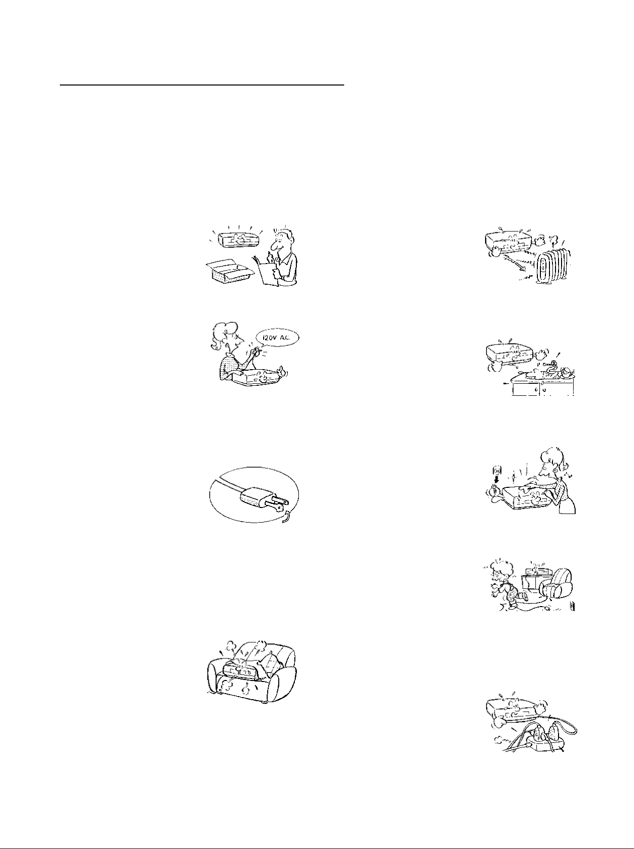
1, Read owner’s manual
After unpacking this product, read
the owner’s manual carefully, and
follow all the operating and other
instructions.
2. Power Sources
This product should be operated
only from the type of power source
indicated on the marking label, it
you are not sure of the type of
power supply to your home, con
sult your product dealer or local
power company. For products in
tended to operatef rom battery power, or other sources, refer
to the operating instructions.
3, Grounding or Polarization
This product may be equipped
with a polarized alternating cur
rent line plug (a plug having one
blade wider than the other). This
plug will fit into the power outlet
only one way. This is a safety
feature. If you are unable to insert
the plugfully into the outlet, try reversing the plug. If the plug
should still tail to fit, contact your electrician to replace your
obsolete outlet. Do not defeat the safety purpose of the
polarized plug.
4, Ventilation
Slots and openings in the cabinet
are provided for ventilation and to
ensure reliable operation of the
p rod u ct a n d to p rotect it fro m o ve rhealing, and these openings must
not be blocked or covered. The
openings should never be blocked
by placing the product on a bed,
sofa, rug or other similar surface. This product should not be
placed in a built-in installation such as a bookcase or rack
unless proper ventilation is provided or the manufacturer’s
instructions have been adhered to.
5. Heat
The product should be situated
away from heat sources such as
radiators, heat registers, stoves,
or other products (including am
plifiers) that produce heat.
6. Water and Moisture
Do not use this product near wa
ter - for example, near a bath tub,
wash bowl, kitchen sink, or laun
dry tub; in a wet basement; or
near a swimming pool and the
like.
7, Cleaning
Unplug this product from the wall
outlet before cleaning. Do not
use liquid cleaners or aerosol
cleaners. Use a damp cloth for
cleaning.
8. Power-Cord Protection
Power-supply cords should be
routed so that they are not likely
to be walked on or pinched by
items placed upon or against
them, paying particular attention
to cords at plugs, convenience
receptacles, and the point where they exit from the product.
9.
Overloading
Do not overload wall outlets; ex
tension cords, or integral
convenience receptacles as this
can result in a risk of fire or elec
tric shock.
Page 3
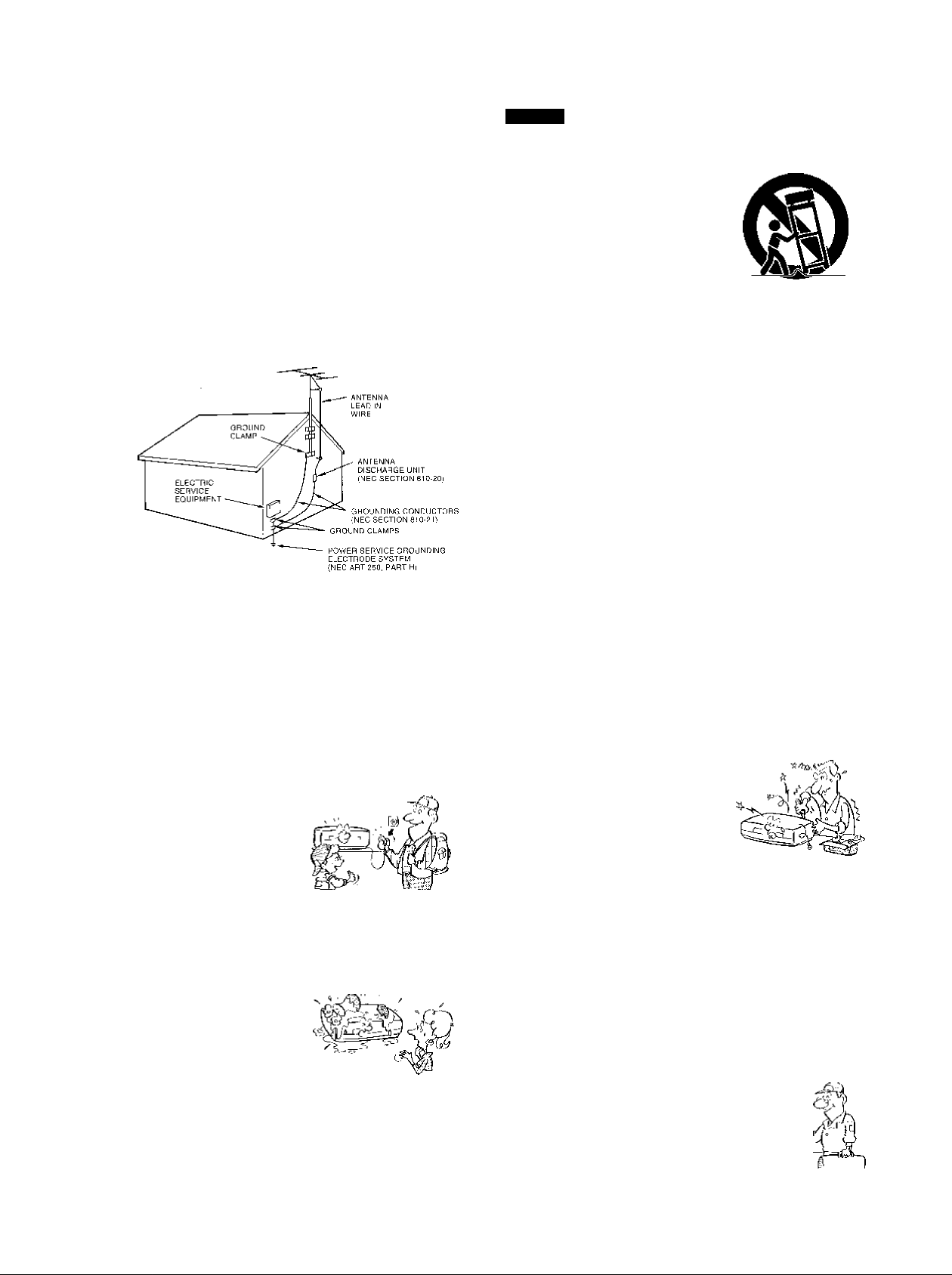
10. Outdoor Antenna Grounding
If an outside antenna or cable system is connected to the
product, be sure the antenna orcable system is grounded so
as to provide some protection against voltage surges and
built-up static charges. Article 810 of the National Electrical
Code, ANSI/NFPA 70, provides information with regard to
proper grounding of the mast and supporting structure,
grounding of the fead-in wire to an antenna discharge unit,
size ofgroundingconductors,1ocationof antenna-discharge
unit, connection to grounding electrodes, and requirements
for the grounding electrode.
EXAMPLE OF Af^TENNA GHOUNDINij AS PER
NATIONAL ELECTRICAL CODE
na-ional electrical code
11. Power Lines
An outside antenna system should not be located in the
vicinity of overhead power lines or other electric light or
power circuits, or where it can fall into such power lines or
circuits. When installing an outside antenna system, ex
treme care should be taken to keep from touching such
power lines or circuits as contact with them might be fatal.
15. Accessories
Do not place this product on an
unstable cart, stand, tripod,
bracket, ortable.The product may
fall, causing serious injury to a
chitd or adult, and serious dam
age to the product. Use only with
a cart, stand, tripod, bracket, or
table recommended by the manu
facturer, or sold with the product. Any mounting of the
product should follow the manufacturer’s instructions, and
should use a mounting accessory recommended by the
manufacturer,
A product and cart combination should be moved with care.
Quick stops, excessive force, and uneven surfaces may
cause the product and cart combination to overturn.
16. Damage Requiring Service
Unplug this product from the wall outlet and refer servicing to
qualified service personnel under the following conditions:
a) When the power-supply cord or plug is damaged.
b) If liquid has been spilled, or objects have fallen into the
product,
c) If the product has been exposed to rain or water.
d) If the product does not operate normally by following the
operating instructions. Adjust only those controls that are
covered by the operating instructions as an improper
adjustment of other controls may result in damage and
will often require extensive work by a qualified technician
to restore the product to its normal operation.
e) If the product has been dropped or damaged in anyway.
f) When the product exhibits a distinct change in per
formance - this indicates a need for service.
12. Lightning
Foraddedprotectionforthis prod
uct during storm, or when it is left
unattended and unused for long
periods of time, unplug it from the
wall outlet and disconnect the
antenna or cable system. This
will prevent damage to the prod
uct due to lightning and power-line surges.
13. Object and Liquid Entry
Never push objects of any kind
into this product through open
ings as they may touch dangerous
voltage points or short-out parts
that could result in afire orelectric
shock. Never spill liquid of any
kind on the product.
14. Attachments
Do not use attachments not recommended by the product
manufactureras they may cause hazards.
17. Servicing
Do not attempt to service this
product yourself as opening or
removlngcovers may expose you
todangerous voltageorotherhazards. Refer all servicing to
qualified service personnel.
18. Replacement Parts
When replacement parts are required, be sure the service
technician has used replacement parts specified by the
manufacturer or have the same characteristics as the origi
nal part. Unauthorized substitutions may result infire, electric
shock, or other hazards.
19. Safety Check
Upon completion of any service
or repairs to this product, ask the
service technician to perform
safety checks to determine that
-"-n-
I /
the product is in proper operating
condition.
Page 4

Various time modes.
With a T-t20 tape, it is possible to record over periods ranging from
2 to 168 hours.
A2, A6, A12, A18, A24, 24, 48, 72, 120 and 16S modes are
expiained in more cfetaii, (See page 21.)
Virtual real-time recording is possible.
It is possibie to virtuai reai-time record in A18 mode.
{See page 21.)
Internal time-date generator.
This VCR inciudes an internai lime-date generator, necessary for
documentation purposes (See page 15.)
On-screen programming.
Menu driven programming simplifies set-up of various functions
including bul not limited to lhe following:
time & dale search, tinner setting, and alarm recording.
Timer recording function.
With timer recording, it is possible to set tv^c programs for each day
of the week as V№ll as one daily program. Up to 15 programs total
are available for timer recording,
{See pages 25 - 28 )
Tape remaining function.
With this feature, it is possible to check the time remaining until the
end of tape during the recording process as well as playback
process. (See page 6, note ©.)
Alarm record function.
With a dry contacl closure upon the alarm input terminal, if is
possible to set the VCR into alarm mode When recording in the
alarm mode, the VCR automatically enters into a mode which
usually is a faster recording mode. This is done so that more
information can be recorded.
One-shot recording possible.
External trigger input makes it possible to record from 1 to 32 fields
and Manual mode.
Alarm memory search function.
This VCR provides an alarm memory function for finding the alarm
event during playback (See page 43.)
Repeat record function.
Repeat record furtdion enables the VCR to automatically rewind
the tape when it reaches the end and restarts the recording
process. (See page 36.)
Restart record function.
This function enables the VCR to automatically restart the
recording process in the event of a power failure. After power is
restored, the VCR will restart the recording process. (See page 24.)
Shuttle function.
With the shuttle dial, a wide varieiv of playback functions are
available. They include picture search, slow playback, field
advance playback, reverae field advance playback, and still
playback {See pages 40 - 41.)
Clean slow and still.
A clean crisp image is crucial and is the main purpose for the
existence of a surveillance recorder. This VCR offers a clean and
noiseless playback, that is essential for surveillance applications.
Time date search function.
With time date search, it is possible to search fora picture recorded
on a certain time and date. (See page 42.)
Head cleaning function.
Head cleaning is automatically performed at the end of timer
recording and at tape end in order to prevent head jamming. There
is also head cleaning once every two hours when operating in time
modes of 24 hours or more.
Auioinatic head clog detection.
When recording in time mode 120 and 168 hours or in the Oneshot mode: video head clog detection is autimatically carried out
once for every two hou^s. When the video head clog is found, head
cleaning is carried out for approximately 10 times. When cleaning is
still not possible, "E-6" is displayed.
Record check function.
By pressing the record check button during recording, the VCR
automatically replays the last few seconds of the recording. (See
page 5, note ®).
Wired remote control function (Option)
The wired remote control allows the following VCR functions.
- Fast Forward • Forward picture search
* Rewind • Reverse picture search
* Pause • Still
* Field advance (forward, reverse)
* Play * Stop
* Play back time
PLEASE READ...................................................................................................1
IMPORTANT PRECAUTIONS...........................................................................1
IMPORTANT SAFETY INSTRUCTIONS
INTRODUCTION ......................................................................................4 - 10
FEATURES..................................................................................................4
TABLE OF CONTENTS...............................................................................4
INSTRUCTIONS IN BRIEF.........................................................................5
VCR DISPLAY.............................................................................................9
WIRED REMOTE CONTROL (Optionj......................................................10
PREPARATION
CONNECTIONS........................................................................................11
CONTENTS OF SCREEN DISPLAY
SETTING THE CLOCK.............................................................................15
ON-SCREEN FUNCTIONS.......................................................................16
DISPLAY SCREEN...................................................................................17
COUNTER DISPLAY.................................................................................19
SETTING THE RECORDiNG/PLAYBACKTIME
LOADING AND UNLOADING A VIDEO CASSETTE
RECORDING OPERATION
RECORDING.............................................................................................23
.........................................
......................................................................
......................................................
!...............................................11 - 22
........................................................
......................................
..............................
23 - 3G
2 - 3
RESTART RECORDING............................................................
TIMER RECORDING..................................................................
ALARM RECORDING ...............................................................
ONE SHOT recording
SETTING OF OPERATION AFTER TAPE END DETECTION.
AUTO REWIND AFTER RECORDING
REPEAT RECORDING
RECORDING WITH THE SEQUENTIAL SWITCHER..............
PLAYBACK OPERATION..................................................................
PLAYBACK.................................................................................
13
21
22
PLAYBACK IN VARIOUS MODE-
TIME DATE SEARCH.................................................................
ALARM SEARCH .......................................................................
NOTICE ...................................................................................................44-50
SIGNAL LEVELS OF IN^UT/OUTPUT.....................................................44
DAILY AND PERIODIC -NSPEGTION.....................................................45
CAUTIONS DURING USE........................................................................47
BEFORE CALLING SERVICE PERSONNEL..........................................48
SPECIFICATIONS....................................................................................50
............................................................
...............................
........................................................
.............................................
............
...........
...........
............
...........
...........
...........
...........
39-43
...........
............
...........
............
24
25
29
31
34
35
36
37
39
41
42
43
Page 5
l^y :■
ilii
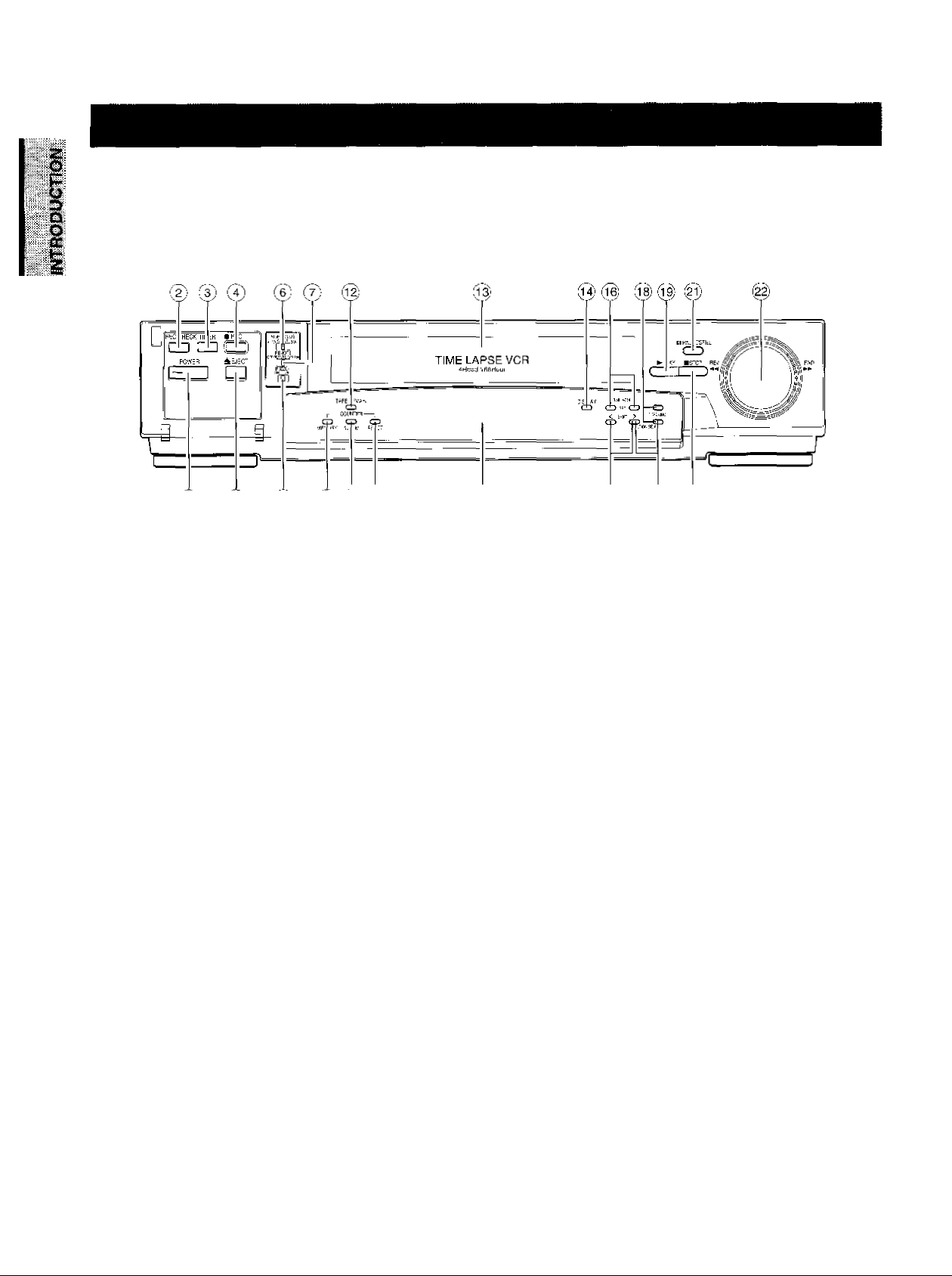
Front Panel
vl) ^
0) (1^
VCR DISPLAY 1_5) Q7)
® POWER button
Press to turn the power ON and OFF.
© REC CHECK button
Press this button while in record mode to check the picture
that was just recorded. After an approximate 2 second
playback the VCR automatically goes back into record
mode.
@ TIMER button
Press this button to set the VCR in timer recording mode.
® REC button
Press to set the VCR in record mode.
© EJECT button
Press to eject the cassette automatically from the cassette
compartment.
® VIDEO MODE switch
In the event of a weak color signal or insufficient S/N ratio,
set this switch to the appropriate setting (color or BfW).
AUTO : Automatically switches the circuit according
to the input signal or playback signal.
COLOR : Forcibly switches the circuit to color mode.
B W : Forcibly switches the circuit to black and
white mode.
Note: ------------------------------------------------------------------
Regardless ot what position the VIDEO MODE switch is in,
the EE output signal is the same as the input signal.
® REMOTE switch (mode lock)
OFF ; Set for normal operation.
REMOTE : Set for use with optional module connected
onto rear panel This will lock the front
panel. Set switch to this position for mode
lock.
OPTION : Set lor external operations when you use an
option module connected onto rear panel.
When switch is set to this position, the front
panel will be operationally limited. (See the
Instruction Manual supplied with the optional
module.)
® BUZZER switch
This is the on/off switch for the buzzer. The buzzer sounds
continually when dew condensation is detected, when the
VCR starts alarm recording, and when recording reaches
to tape end. The buzzer beeps five times with a recordprotected cassette being inserted when REC button or
TIMER button is pressed.
The buzzer sound may be cancelled by setting this switch
off.
® COUNTER MEMORY button
• Press once to set "COUNT. M" (counter memory) on the
VCR DISPLAY. The tape stops at a count of ‘"0000” in
fast-forward mode or rewind mode.
• Press twice to set "ALARM M" (alarm memory) on the
VCR DISPLAY. The tape stops automatically at the first
alarm event detected in fast-forward mode or rewind
mode, Then the VCR is set to playback after still mode.
• Press three times to cancel this function.
® COUNTER ALARM button
Press to display the tape counter or the alarm counter on
the VCR DISPLAY.
® COUNTER RESET button
• Press to reset the tape counter to “0000" while in the
tape counter mode.
• Press to reset the alarm counter to “A-OO" while in the
alarm counter mode.
Page 6

® TAPE REMAIN button
The approximate time remaining on the tape is dispiayed
on the counter (in a 2 hour scale using a T-120 tape) whiie
this button is being pressed.
® CASSETTE COMPARTMENT
insert a cassette into this compartment to load the tape-
® DISPLAY button
Press to dispiay the MENU screen and change the
settings.
® SHIFT < ! > button
Press to seiect a desired menu on the screen.
® TIME MODE A V /SET+ - buttons
• Press either oi the buttons to set the recording time
mode and piaybacktime mode.
• Press either the + or the - button to set the mode and
the numehcai vaiue for each menu on the screen.
© LOCATION SELECT button > / v
Press to change the position of superimposed characters
on the screen.
® TRACKiNG buttons ( A / v )
Adjust to eliminate noise from piayback picture.
® PLAY button
Press to start the playback mode.
@ STOP button
Press to stop tape running.
@ PAUSE/STILL button
• Press during recording to pause recording.
• Press during playback for a still picture.
@ SHUTTLE dial
Turn this dial clockwise and hold:
• To fast forward the tape during the stop mode.
• To operate the forward picture search during the play
back.
• To operate the forward slow play during the still mode.
Turn this dial counter clockwise and hold:
• To rewind the tape during the stop mode.
• To operate the reverse picture search during the play
back.
• To operate the reverse slow play during the stifi mode.
Page 7
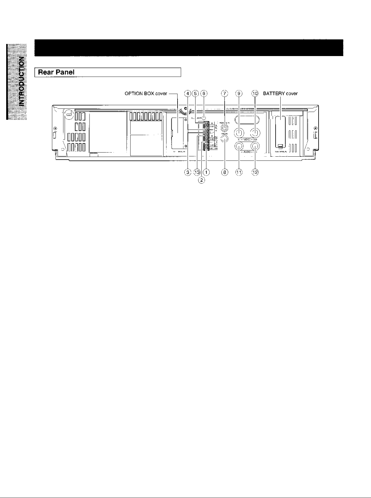
® TAPE END OUT terminal
Signal output terminal to annunciate to other devices that
the tape has run out on the VCR.
m VIDEO OUT connector (BNC)
Output connector for video signal. Connect with a monitor
TV.
@ REC TRIGGER OUT terminal
Signal output terminal to control the switching interval of
the video cameras when connected to a sequential
switcher or multiplexer.
@ ALARM OUT terminal
Output terminal to transmit an alarm signal to peripheral
equipment.
® ALARM RESET terminal
Input terminal to reset alarm recording.
Alarm recording is reset when this terminal is connected to
the ground terminal during recording.
ALARM IN terminal
Input terminal to start alarm recording.
The VCR goes into alarm recording mode when this
terminal is connected to the ground terminal while in the
record mode, record pause mode, or stop mode.
Ce) ALL CLEAR button
Pressing this button will clear the entire time-date, and
timer program memory The power will be turned off at the
same time. Pressing the POWER button will restore
power
@ REMOTE IN jack
Input jack for optional wired remote control.
® MIC IN jack
Input jack for audio signals from a microphone. The RCA
jack input (audio input) is automatically switched off when
this jack is utilized.
® VIDEO IN connector (BNC)
Input connector tor video signal. Connect with an externaf
video source such as a video camera, etc.
® AUDIO IN jack (RCA type)
Input jack for audio signal. Connect with an external audio
source.
® AUDIO OUT jack (RCA type)
Output jack for audio signal. Connect with an externaf
audio equipment.
® ONE SHOT IN terminal
Input terminal to start one shot recording.
The VCR goes into one shot recording mode when this
terminal is connected to the ground terminal while in the
L01, L02 or L03 record mode.
Notes: ----------------------------------------------------------------
> ALL CLEAR button
Do not use this function (ALL CLEAR) frequently.
Press this button only when an abnormality (ex. VCR
display does not turn ON.) occurs.
When this button is pressed, the power turns OFF and
each data stored (ex. dock, timer program, etc.) is cleared
and returns to the initial setting status. It will be necessary
to re-program the VCR after turning the unit on again.
• OPTION BOX cover
This VCR provides an optional port for connecting an
optional module to the rear of the unit.
If you would like additional information regarding the
available options for this VCR please consult your dealer.
The installation of the optional module should be per
formed only by qualified technical personnel.
Page 8
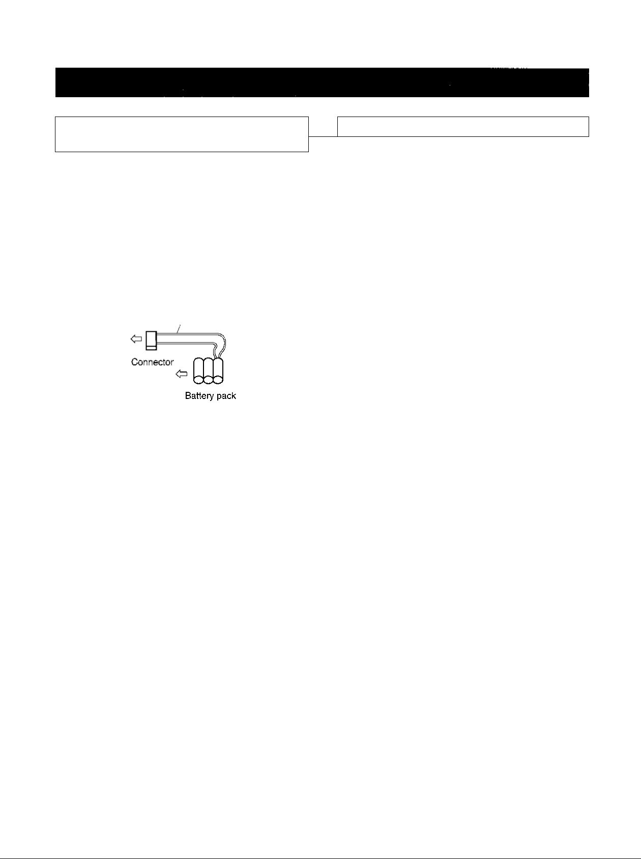
A Word on the Exclusive 3N-100AAS
Battery Pack
The nickel-cadmium battery pack (3N-100AAS) is used for
power source of the built-in clock and memory circuit.
Charging the Battery Pack
specification of Battery
■ Temperature
For charging
For operating
For storing
Charging time
O^C to 80^C
-20^C to 80^C
-30"C to 80X
more than 48 hours
1. Turn on the power of the VCR.
2. The battery pack in the VCR is charged.
Battery Installation
Removal:
1, Remove the battery cover,
2. Disconnect the connector in the VCR.
RED wire
Installation:
1. Install the battery pack placing the red wire upside, and
connect the connector on the battery pack to this VCR.
Make sure the polarities (+) and {-) are correct.
2. Close the battery cover.
Note:------------------------------------------------------------------
If the Battery Pack is removed, the memory data will be
erased. In such a case, perform the setting from the first step.
Notes:
Use only for this VCR.
Do not dispose of the batteries into fire
Do not short circuit the terminals.
Do not modify or disassemble.
Avoid dropping, unnecessary shocks.
8
Page 9

AV '
' K«.-.v ivi:; i:,;; fíjiios
w
H Counter/Aiarm Counter/Remalning Tape/Error Mes
sage indicator
T
PLAYI i REC
\4Mt
j- ? ?
COUNT. ALARM
1 i t Ì t í t f
U U U U
M MI
ALARM
PW.FAIL
sp L( U U
EP U U U
I Cassette indicator
Lights when a tape is inserted.
I Counter memory indicator
Lights when the counter memory is selected.
I Aiarm Memory indicator
Lights when the alarm memory Is selected.
I Aiarm indicator
Lights during alarm recording and blinks after an alarm
recording cycle is completed.
I PW.FAiL (Power Failure) indicator
Blinks when a power failure occurs.
I TAPE operation indicator
Displays as shown below, depending on operational
modes.
• Press the ALARM button to display the alarm counter.
- Press the ALARM button again to return to display the
counter.
- Press the TAPE REMAiN button to display the remaining
tape time.
• When an abnormality occurs during operation, the error
code is displayed.
E-1: Abnormality on reel rotation during tape running,
E"3: Abnormality on cylinder rotation during recording
and playback.
E-4: Abnormality on tape loading mechanism.
E-5: Video tape is cut.
E-6: Head clog.
E-8: Dew condensation.
S Dew indicator
Blinks when the dew condensation has developed inside
the VCR,
S Timer indicator
Lights when the timer recording button is pressed and the
VCR has been set in timer record mode.
¡Q Record/Playback Time indicator
Displays record/playback time mode.
Playback
Playback
Still
Slow
Field Advance
Reverse
Playback
Forward
Picture Search
Reverse
Picture Search
Reverse
Field Advance
PLAY
PLAY
II
I PLAY
I ►
iPLAYl
II ►
PLAY
I PLAYi
iPLAYl
IPLAYl
M II
Record
Pause
I
Time-lapse
Fast Forward
Rewind
Other than playback
REC
REC
REC
I ►
I
Page 10
:„н^.
..........
.
MiiilMiiMMliniillMil^^ AiiiiM
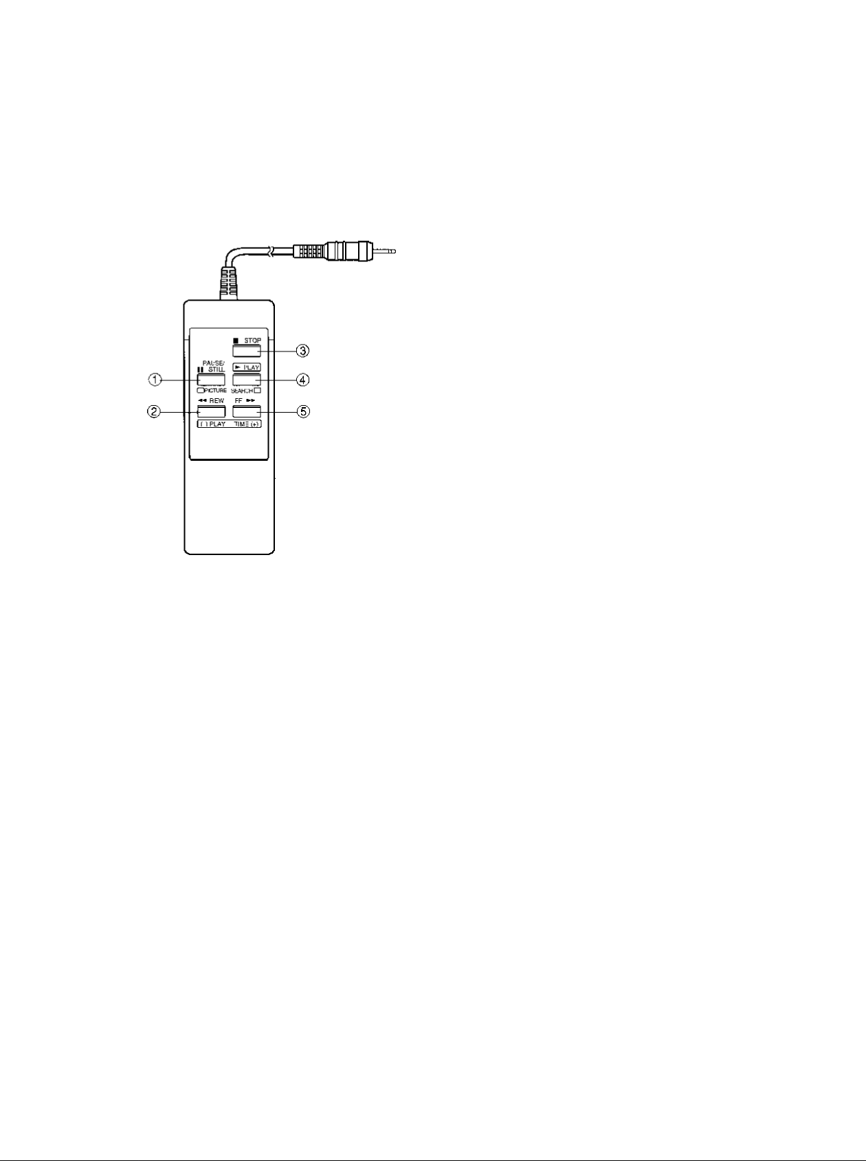
® PAUSE/STILL button
• Press during recording to pause the recording.
• Press during playback to play back a still picture.
© REW button
• Press to rewind the tape.
• Press during playback for reverse picture search.
To release the reverse picture search mode, press the
PLAY button.
• Press the REW button while pressing the PLAY button,
the time mode can be selected.
• Each time pressing the REW button during still playback
mode, the Reverse Field Advance playback (one field)
will be carried out.
@ STOP button
Press to stop tape running.
® PLAY button
Press to start play back.
® FF button
• Press to fast forward mode.
• Press during playback for forward picture search mode.
To release the forward picture search mode, press the
PLAY button,
• Press the FF button while pressing the PLAY button, the
Time mode can be selected.
• Each time pressing the FF button during still playback
mode, the Field Advance playback (one field) will bo
carried out.
'•tin: .tiiir 1^1 IB
Note:
-----------------------------------------------------------------
If your wish to obtain the wired remote control, please consult
your dealer.
10
Page 11
^.i, i"
il"
Preparation
:::-;^!';i
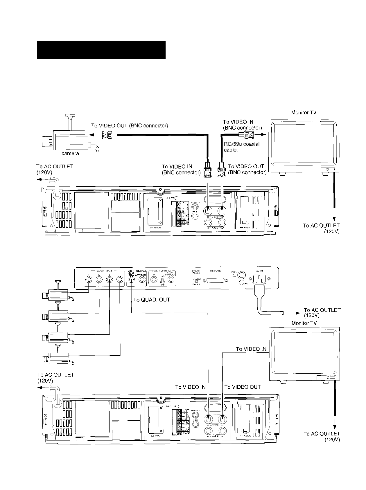
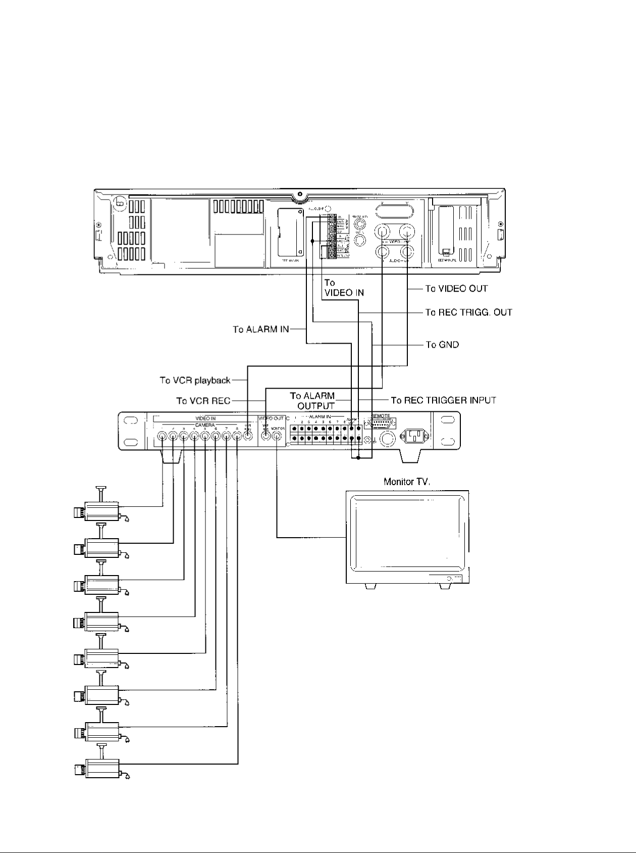
Connections
Connection with a Video Camera
: V":
■
Quadrant picture unit
11
Page 12
Typical Connection with the Sequential Switcher
When connected with a sequential switcher, set the alarm recording mode to MANUAL by menu screen.
For further details, consult the instruction manuals of the connected devices.
Frame Sequential Switcher
AC120V
To AC outlet
When using the VCR connected to a frame sequential switcher, pay
attention to the following matters.
■ When playing back in the A12, A18 or A24-hour mode, mixing ot
pictures from other channels may occur If this occurs, play back in a
mode other than the A12, A18 or A24-hour mode.
■ If the following phenomena occur during playback in a time mode of
24 hours or longer, adjust by using the TRACKING button.
1. Mixing of signals from another channel.
Go to slow playback and press the TRACKING button to adjust
until the picture appears from the channel you want to view.
2. Picture waves up and down.
Press the TRACKING button during still picture playback and
adjust the picture until the picture stops waving up and down.
12
Page 13
Y
■ - - ■ • r ■ - - : ^ ^ ■ '
The normal MENU screen provides six menus after the initial screen for clock setting. Each MENU screen is shown below.
Press the DISPLAY button for a MENU screen. The menu is selected by pressing the SHIFT button. Then press the SET button to
proceed to the next screen. Use the SHIFT button and tho SET button for settings and adjustments in the same manner. To return
to the initial screen press the DISPLAY button.
Monitor Screen (initial screen) MENU Screen (initial screen)
HCLCCK 5EF|
SETUP
[ITSPI AV MODE
TIME DATE SEARCH
tWD=:OISPLAYl
Monitor Screen (normal screen) MENU Screen (normal screen)
fCLOCK ADJUST~I
SbILP
DrSFLAY MODE
PROGRAM
ALARM RECAI I
TIME DATE SEARCH
8/26/96 WED
17:30:02 A 2
END-EDISPLAY]
CLOCK ADJUST
LSETUP
DISPLAY MODE
PROGRAM
ALARM RECALL
TIME DATE SEARCH
END-EDISPLAY]
CLOCK ADJUST
SETUP
________
I DISPLAY MOdFI
PROGRAM
ALARM RECALL
TIME DATE SEARCH
END=[DTSPLAY]
CLOCK SET Screen
CLOCK SET
(DAYLIGHT
SAVING TIME]
(MONTH) (DAY) (niAR)
1 / 1 / '95
SUN
(TIME) 0:00
MENU-[DISPLAY]
OUT
CLOCK ADJUST Screen
CLOCK ADJUST
(DAYLIGHT
SAVING TIME) IN
(MONTH) (DAY) (YEAR)
S / 28 / '96
WED
(TIME) 17:30
M£NU=[D]SPLAY1
SETUP Screen
ALARM REC TIME IBS
ISHOT REC FIELD IF
RESTART REC OFF
TAPE END MODE STOP
SPEED A 2H
INTERVAL 0,?S
ALARM STOP
MLNU=[CrSPLAY]
DISPLAY Screen
(UAIE) ON
(DAY OF THE WEEK) ON
(TIME)
(SPEED)
(VCR)
(ALARM)
a2H/£4H)
(CHAR.LINES)
MENU-EDISPLAY]
ON
ON
OFF
OH
24H
Comment
Setting of clock.
Unless the dale-time is
adjusted, the “PROGRAM”
and ALARM RECALU' will
not appear on the MENU
screen.
Correction of date-time.
Setting of alarm recording
mode'jrecording time,
recording model
Setting of One-Shot
recording mode (number of
recording fields, recording
intervals).
Setting of recording for
restoration of power following
a power failure.
Setting of operation after
detection or tape end (tape
end detection mode for tape
end detection during
recording and when an alarm
recording Is made).
Setting of display screen
(date, day of week, time,
recording time, VCR number,
alarm).
Setting of time display (24H,
12H).
6
13
Page 14

PROGRAM Screen
MOI ON
CLOCK ADJUST
SEfUP
DI5P-AY MODE
I PROGRAM 1
ALARM RECALL
TIME DATE SEARCH
END-[DISPLAY I
MOZ ON
TÜI ON -TU2 ON -■
^E1
Vit?
THl
THE ON
ALARM RECALL Screen
MENU • ■
C_0CK ADJUST
SETUP
DISPLAY MODE
PROGRAM AL5 -/
lALARM RECALLI AI
TIME DATE SEARCH
end=:disrlay]
1 • ^
ALl ■ ■ /
AL2
AL3 --/
AL4 --/
AL7 --/
1ST
TIME DATE SEARCH Screen
C.OCK ADJUST
SETUP
DISPLAY MODE
PROGRAM
ALARM RECALL
ITINF DATE SEARCHl
HAY
HOUR
MINUTE
SEARCH FORKARD
^ 120L
-- 120H
ON
ON
ON
HENJ-EDISPLAY]
ALARM RECALL
TIME DATE SEARCH •
REVERSE
i20K
12ÜH
120H
12DH
120H
IEOH
1
0
DO
recording.'din
Alarm recall
display
Set the day and
time to be
searched and
searching
direction.
№
pML.,...
end=:display]
H£NU=[DISP_AV}
14
Page 15

1еттш0 fflE еьйск;
An internal clock generates time and date for superimposing on the monitor screen. Adjust the time from the MENU screen (initial
screen). After the clock is set, the data and time modes are displayed on the monitor screen {live picture).
Operation
In case of setting to 5:30 PM, V^ednesday, August 28, 1996;
9
K
<
CL
m
Ш
CL
Press the DISPLAY
button,
DISPLi\V V
m CD CD -o
T <
CD CD vO
.:catcn:--:i rc’’
Press the + SET button.
ms PLAY VTUENr:r:=,-s
< =ИгтХ
CD О VCD
irri-K^NISt.tCl
Press the + SET button
and set the DAYLIGHT
SAVING TIME to IN
DIgp ДУ V l'.<L'.iC'.iA
CD C—> yii-
CD О vo
-OCATa^i F^-
[clock sftI
-SETUP
d:sp-ay mode
TIME DATE SEARCK
END-LDISPI AY]
CLOCK SET
[DAYLIGHT
CAVING TIME) [ CDTl
(MONTH) (DAY) (YEAR)
1 / 1 / '9b
SUN
(TIME) [):U0
MENU'-[DISPLAY]
CLOCK ADJUST
(DAYLIGHI
SAVING TIME) |~7n1
(MONTH) (i)AY) (YEAR)
I / I '05
GUN
(TIME) 1:00
MENU=[DISPLAY]
Press the > SHIFT
button to blink Year and
press the + or - SET
button to set to "96”.
DISPLAY VTMEMCnrA
Press the > SHIFT
button to blink Time in
hours and press the +
SET button to set to ''^7"
DISPLAY VTIK'EK'0:1V^
^D ^D sEr
Press the > SHIFT
button to blink Time in
8
minutes and press the +
SET button to set to "30”.
V-'^E'^CCE,^
^D ^D =ET 55
CD о rf- CD nCD
>
a VCD
#
C»Yir,-KS:±Cr
< 3M-rT
O CD vCC)
rf^lON EELEC’
< shftT
о о vO
C^pllg'JriiLhC
CLOCK SET
(DAYLIGHT
SAVTNC IIME) IN
(MDNIK) (DAY) (YEA О
Й / ES /
WFD
(TIME) 1:00
MENU-[I)1SPLaY1
□ OCK SET
(DAYLlGhf
SAVING TIME) IN
(MONTH) (DAY) (YEAR)
e / 2B / ^96
WED
i.TiMEj [i7|:ao
MENU=IDISPLAY]
CLOCK SET
(UAY LIGHT
SAVING TIME) IN
(MONTH) (DAY) (YEAR)
8 ! 28 / '96
WED
(TIME) 17-Щ]
MENL-[DISPLAY]
15
Press the > SHIFT
button to biink Month
and press the + SET
button to set to “8”.
DISPLA.y
lUEMCDE/4
CD ЕЁ- ^ aQ
< SHIFT T
CD О VCD
limiONfiF. -':;i
Press the > SHIFT
button to blink Day and
press the + SET button
to set to “28".
DUPLAY v"iHF uriiit A
C^D (^D vF"
< ?M|rT T
CD O VCD
ON ¿ELECT
CLOCK SET
(DAYLIGHT
SAVí^G TIME) IN
(MONTH) (DAY) (YEAR)
m / 1 / '9и
(TIME) 1:00
(DAYLJGH"
SAVING "IME)
(MONTH) (DAY) (YEAR)
(IIME) 1:00
TUE
MENU-EDISPI AY]
CLOCK SET
В /¡Ш / ’УЬ
MON
H£NJ-[D:SPLAY]
Press the DISPLAY
button to start display of
the set date and time.
¥
\а1';ё'^о:е.'\
CD £ET ^D
< SHF- >
О о vo
Lca'\-i:>. VFi r;:-
niS°LAY
Iclqck adjust I
SETUP
DISPLAY MODE
PROGRAM
ALARM RECALL
TIME DATE search
END-LDISPLAY]
Press the DISPLAY
button to return to the
;n
10
normal screen.
DISPLAY
О EET О
¥ ^ ~
■ < SHIFT ^
■R/'SKINCi
О CD О
LCCi-|CN IICLlC'
17;30:C2 A 2
WED
Page 16

aN^sgweiN FufiisyioNi
When the power is turned ON, the time and date modes are displayed on the monitor screen (live picture). On-screen displays are
not available in the event of no video input signal.
Date-Time Display
VCR display
® Date
I—I
I 8/28/96 WEDi
¡17:30:02 A 2|
I
------------------1-----------------------------
@ Time
0) Date : Displayed with the month-day-year.
@ Day oi the week : Automatically set to the correct day of the week when the date is set.
@ Time : Set to 24-hour cycle at factory.
It is possible to modify to 12-hour (AM/PM) cycle display.
© Playback/Recording Time : Playback or Recording time display
On-Screen Position
Press the LOCATION SELECT button to adjust the display to desirable position.
The display moves in the direction shown by the arrows.
CD ^CD
LCCATICT in rc"
Press this button : To down
Press this button : To right
: Day of the week
|_j
Playback/Recording time
z
0
1
2
iaeli
&
However, during the date-time display screen, pay attention to the following when
setting the date and time display positions:
When the display is set to an end of the monitor screen as shown in the figure,
synchronization instability or color flickering may occur in some monitor TVs.
16
Page 17

■ EN • . •. : ^
Set the MENU screen to DISPLAY screen, and select or set each item.
Before operation, set the MENU screen to DISPLAY screen (See page 13.).
Note:------------------------------------------------------------------------------------
Press the DISPLAY button twice to return from the display screen to the monitor screen.
MM
iv,',-''.
Operation
Erasing the date display.
Press the < or > SHIFT button to blink DATE and press
the or - SET button to go to OFF.
DISPLAY vTr;Er/GC€/;.
'Hacking
Ó "CD
LCCú.TIC'NSr.nr-
Changes between OFF and ON
each time the + or - SET button
is pressed.
Erasing the day of the week display.
Press the < or > SHIFT button to blink DAY OF THE
WEEK and press the + or - SET button to go to OFF.
DISPLAY Y ’-'E
CD j
<
CD "CD ^CD
'W’ LOCATCfSiLECT
Changes between OFF and ON
each time the SET button is
pressed.
Erasing the time display.
Press the < or > SHIFT button to blink TIME and press
the + or - SET button to go to OFF.
Changes between OFF and ON
DISPLAY yTklEktcnEA each time the + or - SET button
^ is pressed.
CD ^CD
L0"iTlGN SE.ECT
Display Screen
(DATE}
(DAY ÜF THE WEEK)
(TIME)
(SPEED)
(VCR)
(ALARM)
(1PH/24H)
(CHAR.LINES)
HENU=[DISPLAY]
(DAIt)
(DAY OF THEWEEK) IOFFI
(TIME)
(SPEED) ON
(VCR)
(ALARM) ON
(12N/24H) 24F
(CHAR.LINES)
MENU=[OISPLAY]
(DATE) DN
[DAY OF THE WEEK)
(TIME)
(SPIED)
(VC^)
(ALARM) ON
(12H/24H) ZAH
(CHAR.LINES) 6
M:hU-[DL$PLAY]
CN
ow
ON
OFF
ON
6
ON
ON
OFF
6
ON
ON
OFF
Monitor Screen
e;28/96
17:30:C2 A 2
Erasing the speed display.
Press the < or > SHIFT button to blink SPEED and press
the + or - SET button to go to OFF.
DISPLAY VlklEk^CDE.^
CD CD ¿ET CD
< ■» >
Ci>¥ CD
LÜCAT0N SF.
TR.iCKJNij
VCD
Changes between OFF and ON
each time the + or - SET button
is pressed.
17
(DATE) O'J
(DAY OF THF WEEK) ON
(^IME) ON
(SPEED) [oFfI
(VCR) OFF
(ALA^M) ON
(I2H/2^H:i 24H
(CHAR.LINES) 6
MENU-EDISPLAY]
e/28/90 WED
17;30:02
Page 18

Note:
Press the DISPLAY button twice to return from the display screen to the monitor screen.
Operation Display Screen
Dispiaying the VCR number.
Press the < or > SHIFT button to blink VCR and press
the + or - SET button to set the VCR number.
DISPLAY V
CD CD i IT CD
CDiCD
TFAiIX'sCS
LCyjJillCi-J SELECT
Changes as shown below each
time the SET button is pressed.
OFF ^ V01 V02 ^ V03 ^
V04 ^ VOS V06 ^ V07 ^
VOS ^ OFF
Dispiaying the number oi alarms.
Press the < or > SHIFT button to biink ALARM and press
the + or - SET button to go to OFF.
DISPLA.V vTVrVcc:.^
CDiO ^CD
L_j
c >
—i ■ —
-CiC.i,rOr-,oELE[;T
■RACK 'JG
Changes between OFF and ON
each time the + or - SET button
is pressed. When an alarm is
input, the day of the week display
changes to the alarm number.
Displaying the hour display.
Press the < or > SHIFT button to blink (12H/24H) and
press the + or - SET button to go to 12FI.
Changes between 12FI and 24FI
DISPLAY
f~~i SET c: 3 At 1
< At >
CD ! CD
LCC.«|'I0K EELEST
each time the + or - SET button
is pressed.
r* DISPlAY
(DATE)
(DAY OF THE W£Ek>
(TTMF)
(SPEED)
(VCR)
(ALARM)
(I2H/24H)
(CHAR.LINES)
■ • DISPLAY
(DATE)
(DAY OF THE WEEK)
(TIME)
(SPFFO)
(VCR)
(ALARM)
a2D/24H)
(CHAR.LINES)
1 menu=[display:
(DATE)
(DAY OF THE WEEK)
(TIMI)
(SPEED)
(VCR)
(ALARM)
(I2H/24H)
(CHAR.LINES)
•
ON
ON
ON
ON
\M1
ON
24H
MENU=[DISPLAY]
6
ON
ON
ON
ON
OFF
QU
24H
6
ON
ON
ON
ON
OFF
ON
UM
HFNU=[mSPLAY]
6
Monitor Screen
VCR number
8/28/96 WED
17:30:02 A 2 VOl
Alarm number
8/28/96 ACl
17:30:13 A 2
1
This function enables to indicate and record information
from cash register or ATM using a specified option box.
Press the < or > SHIFT button to blink CHAR.LINES
1.
and the + or - button to go to "6”.
2.
Press the + or - button to select the characters of line
number. Each time pressing the + or - SET button^ the
display changes as follows.
If you select
[DATE] ON:
[TIME] ON
f}
6^1->2^3^4^5
[DATE] OFF:
[TIME] OFF
■}
(DATE;
(DAY OF THE WEEK)
{TIME)
(SPEED)
CVCR)
(ALARM)
(I2H/?4H)
(CHAR,LINES)
HENJ=[DISPLAY]
ON
ON
ON
ON
OFF
ON
12H
O]
18
Page 19

CbUNTliR DISPLAYS
Counter Memory
When the counter is set to “0000" at a location that you want to see again during recording and playback, the tape will slop in the
vicinity of “0000” during rewind and fast forvi'ard.
, ic
" №
When the alarm counter is displayed, press the
i
ALARM button to set the display to the counter
display.
2
UJ
fB12
I
------
COUNTER--------1
CD O CD
MEMORY ¿1^1 RESET
Press the RESET button at the location you want to
see,
|:Xil
I
----
COUNTER
-----
1
CD CD Q
MEMORY ALARM R*F
►
; n M r J
r i U LJ
^ nnnn
► U LJ U U
5P
5P J_J
Alarm Memory
When you want to view the location where alarm recording was performed.
Press the STOP button,
► FLA^ ■S'^OP
( L. )
|oi2.
TrecI
/ n n n
r r U U
fALARM
/ t
n
} f L
Press the COUNTER MEMORY button to make
"COUNT.M” (Counter Memory) to light.
H
J
f
I
----
uCUNTER’-----1
Q CD CD
ME-WV AU^RM RESFT
Turn the SHUTTLE dial to set rewind or fast forward
after STOP button is pressed.
4
H
Ti
]fr
Turn the SHUTTLE dial to set rewind or fast forward.
i-^c:
4^
[play
■ ■
■ 1
r
f n M n
' u < u
f n n 1 i
t U J u
n n n n jQ
When the tape reaches the
alarm recorded position, The
VCR automatically enters the
still picture mode.
1 ^LlI
O J
t t L
—
f t
H
D
L
H
i
19
Press the COUNTER MEMORY button twice to make
“ALARM. M"to light
I alarm!
; j I i i n
f f j_i u
I
------
COUNTER--------,
^ CD CD
m™ry reset
U J
i * C
Press the PLAY button,
^PLAY BSTCP
c:
Page 20

Notes: ---------------------------------------------------------------------------------------------------------------------------------------------------
In the cases shown below, Alarm Memory search may be not carried out.
■ If the alarm recording is not carried out for more than those listed in the following chart then, the alarm may be skipped.
■ If the alarm recording Interval is not left for more than those listed in the following chart then, the alarm may be skipped.
■ If there is not enough time between the beginning of the alarm search and the first alarm activation If the time period is shorter
than those listed in the following chart then, the first alarm may be skipped.
Record
mode
A2 or A6 2 s 7 s
A12 15 s 50 s 35 s
A18 7s 25 s 15s
A24
1 Miinimum alarm recording
time needed
30 s 95 S 65 s
Minimum alarm recording
interval needed
Minimum recording time needed between
start of search and first alarm activations
5s
Tape Remain
When the TAPE REMAIN button is depressed during recording or playback, the counter display changes to the remaining tape
display. The remaining time is the approximately estimated time in the A2-hour mode to tape end.
IREC
►
u
t «
* The remaining time is the approximate remaining time.
* Displays the remaining tape time estimated in the A2-hour mode.
During computation of the remaining time, the following display appears.
IREC
►
• When the VCR has been used in the recording mode over a long period, it may take considerable time for computation. When
operating at fast speed in the A2-hour mode, the computation is faster.
J t i
f f
TAPE REMAIN
CD
Q
<
Note:-----------------------------------------------------------------------------------------------------------------------------------------------------
It is possible to compute the remaining time forT-120, T-90, T-60 and T-30 tape. The display will not be correct for other kinds of
tape.
Error Message
When an abnormality occurs during operation, the error code is displayed.
At the same time, the buzzer will sound continuously.
f I
j j
• When the error code “E-1 ” to “E-4” are
displayed, consult with your dealer.
• When the error code “E-5” is displayed,
the tape is cut. Replace with a new tape.
• Regarding the error code "E-6 " Display
When recording in time mode 120 and 168 hours or in the One-shot mode, video head clog detection is automatically carried
out once for every two hours. When the video head clog is found, head cleaning is carried out for approximately 10 times.
When cleaning is still not posible, ''E-6" is displayed and the RED display blinks on the monitor although recording continues.
In such a case, cleaning of the video heads is required.
•
Code Number Condition of Abnormality
E-1 Abnormality on reel rotation during tape running.
E-3 Abnormality on cylinder rotation during recording and playback.
E-4 Abnormality on tape loading mechanism.
E-5 Video tape is cut.
E-6 Head clog.
E-8 Dew condensation.
20
Page 21

SETTING THE RECORbiNG/RLAYBACK TIME
I Before perfornning playback/гecoгciing^ it is necessary to set the desired time mode,
TIME MODE button: Recording/Playback time
Consult the following table to select a correct mode for your purpose.
VIRTUAL REAL TIME & TIME LAPSE VCR INFORMATION CHART
Record/Play Available Time
Mode display
A2 2H
FP A 6
A12
A' u 1. .■. ^ ,11X ■ ; ; '-1.^^
(Using T-120)
.....
ÎvÎmiîfiealTimèïmide»
A24
24 24 H
48 48 H
sp 72
120 120 H
sp 168
LOI
L02 7,200 H ri)
L03
10,800 H (*1)
(Using T-160)
2 H 40 M
6 H
14 H 18 H40 M
8 H 1/60S
,■■■ = «
1Ô H' ^
26 H
72 H
168 H
3,600 H {*1}
34 H 40 M
32 H 0.20s
64 H 0.40s
96 H
160 H
224 H 1.4s
Recording
interval
1/60S
0.12s
0.22s
0.60s
1.0s
60s (*1)
120s (*1) 2fields/2 min (*1)
180s (*1)
Recording field
60.0 fields/s Possible Continuous
60.0 fields/s Possible Continuous
8.57 fields/s
4.62 fields/s
5.00 fíelds/s Impossible Intermittent
2.50 fields/s
1.67 fields.fs
1.00 fields/s
0.71 fields/s
2 fields/1 min (*1) Impossible Intermittent
2 fields/3 min (*1 ) Impossible
Audio record
Possible Continuous
■ ■ "
Possible
Impossible Intermittent
Impossible Intermittent
Impossible Intermittent
Impossible Intermittent
Impossible Intermittent
Continuous
Tape running
:!: .:
...............
Intermittent
i 5'' a■■
: ^,'r II
■ ■
(^1 ): Without an alarm trigger input and an one-shot trigger input.
• The possible recording time depends on the type of video tape used.
• Audio recording is possible in the A2, A6, At2, A18 and A24 hour modes.
• The A12, A24, 24, 48, 72, 120 and 168 modes are time lapse modes.
• For one-shot recording, set the VCR in the LÛ1, L02 or L03 record mode.
• In LOI, L02 or L03 modes, the VCR is set to recording pause mode. The alarm recording starts by an alarm trigger signal
input, and the VCR is set to recording pause mode again to wait for next alarm trigger input. Also the one-shot recording starts
by an one-shot trigger signal input, and the VCR is set to recording pause mode again to wait for next one-shot trigger input.
When recording pause mode continues for appointed time (LOI : 1 min, L02: 2 min, L03: 3 min.) without an alarm trigger and
an one-shot trigger input, the VCR forwards the tape 2 fields with recording to protect the tape and the video head from
damage.
■ HOW TO OPERATE 24 HOUR VIRTUAL REAL TIME MODE
• In order to operate 24 hour virtual real time mode, please use T-160 VHS video tape with A18 record mode. A18 mode means
that T-120 tape will run 18 hours. However, if you use longer length of video tape which is T-160, it will record up to 24 hours
with A18 mode. Also, when you use A18 mode for recording, you will get 20 fields of video information per second, A24 mode
will be less than 5 fields video information per second. {Refer to the above chart for the details.)
• When using the T-160 tape, it will be necessary to replace the tape with new one and make a cleaning of the mechanical deck
of this VCR more frequently. Because, the thickness of T-160 tape is about 3/4 of T-120 tape, so durability, mechanical
21
strength, etc. of the tape are inferior to T-120 tape.
Page 22

LèigN¥Wtyit»tLaai(Ma:A:Mgegg
Cassette compartment
EC
?
I Loading a cassette
Insert a cassette in the Cassette Compartment.
■ Power goes on automatically and the cassette indicator
lights.
:ECC-lt< Mvri-tTfr"
a i=ia
□
T
Cassette Indicator
Blinks when inserting or removing a cassette.
Remains lighted when a cassette is inserted even if the
power is turned OFF.
Unloading a Cassette
Turn the power ON.
POWER
Press the EJECT button.
A EJECT
Safety Tab
A video cassette is equipped with a safety tab to prevent
accidental erasure. When the tab is removed, recording is
not possible.
Cassette indicator
n n n n
► u u u u
.K U
t r
H
h
L
If you wish to record on a cassette with the tab removed,
use adhesive tape to cover the hole.
22
Page 23

Rec
r< C yiijr jri M i Ui
Turn on the power for this VCR as well as associated
devices of the surveillance system including the video
camera and monitor TV.
Adjust the monitor TV so that the picture from the
video camera is displayed properly.
Check that the date time display on the monitor TV is
correctly displayed.
ÉiiiéiiiiÀM
Insert a video cassette to this VCR.
• Check that the safety tab on the video cassette has
not been removed.
CD a Q
TIME LAPSE VCR
Ï
Select the recording time mode.
[CÜ1
rf rf
'v'"r;EMCCEA
C) SET
Press the REC button.
[0^
#REC
o
n n
u u u u
« nnnn
► u u u u
t \
3= J i _/
1rr
' i u
Set the various functions such as timer recording,
alarm recording, restart recording, tape end, etc.
Notes:
When the PAUSE button is pressed during recording, the VCR goes to the pause mode. To release, press either the PAUSE
button again or the REC button. If the VCR is in pause mode for longer than 10 minutes the VCR will automatically go into stop
mode to protect the video tape and heads.
Repeat recording, restart recording, alamn recording, etc. also operate during recording.
When recording is interrupted or the recording time is changed, the pictures may be disturbed at that location.
It a power failure should occur, it is possible to resume recording in the same time mode as long as the power is restored within
approximately 10 days.
During repeat recording, pay attention to the following points.
•Timer recording and alarm recording is not possible during automatic rewind.
• The buzzer does not sound even at tape end.
• When an operation button is pressed during automatic rewind, the repeat recording function does not operate. Reset to the
recording mode.
The time mode button is not accepted during alarm recording or timer recording.
Make sure to carry out daily check for repeat recording or timer recording
23
Page 24

RESTART RECORDING
Setting the Restart Recording
On the SETUP screen set RESTART REC to ON,
Press the DISPLAY
button. The MENU
screen appears on the
monitor screen.
DiaPLAy
0 SET O aQ
¥
< SHIR >
CD CD vo
LCO^-lcr-j FFI cf-
Press the < or >
SHIFT button to blink
SETUP and press the +
or - SET button.
DISPLAY
vT';e';cce.'\
g ^ I O CD
^■^CD
CLOCK ADJU^sl
SETUP
DISPLAY MODE
PROGRAM
AL.ARM RECALL
TIME DATE search
CL3CK ADJUST
i SETUP i
DISPI AV MODE
FRDGRAH
Al ARM RECALL
TIME DATE SEARCH
■ ' ■ i ■ ■ , • ;
bND=[DISPl AV]
END“[DISPLAV]
Press the < or >
SHIFT button to blink
RESTART REC.
Dg.V
VlMEMrPE A
5TT ^D
ALARM REC TIME 15S
ISHOT REC hlLLD IF
RESTART REC OFF
TAPE END MODE STOP
SETUP
SPEED A
INTERVAL 3.2S
ALARM STOP
(±i!^o
HEMU=[DISPLAY]
Press the + or - SET
button to go to ON.
CD
VTME MCDEAs
C 1 SF" r t aC^
Tr
CD VCD
LXATlO'g s" Fcr
DISPLAY
alarm RFC TIME 15S
ISHDT REC FIELD IF
RESTART REC I ONI
TAPE END MODE STOP
SETUP
SPEED A ?M
INTERVAL 0.£S
alarm stop
MENU“ID[SPLAV]
Note:
When a power failure occurs (10 days or [ess in duration) during recording or timer recording, the VCR resumes automaticaily to
the same mode when the power is restored regardless of whether "RESTART REC" is ON or OFF.
When the power is recovered after more than 10 days have passed, the tape rermains at the position where it stopped when the
power failure occurred.
24
Page 25

ilK
TherG are two kinds of timer recording. One is daily timer recording, and the other is weekly timer recording.
Once the timer programs are set, the VCR can retain all programmed information in the event of a power failure (10 day maximum
memory storage). Before setting timer programs, make sure that the present time is correct. (See page 15-16.)
' Setting the Timer Program
The timer programs are set on the two pages of PROGRAM screen which provides “on/skip", start time, end time and recording
time mode for setting.
The blinking position moves to right direction or downward with the > SHIFT button, and to opposite direction with < SHIFT
button. When the program event is set to SKIP, timer recording will not be carried out even if the start or end time is set.
PROGRAM Screen (2)
Monday 1 -
3-
Tuesday 1 —
2-
Wednesday 1 —
S'-
Thursday 1 —
ON, SKIP displays —
Starting hour display
2-
PROGRAM Screen (1)
-
Moi rw
TUI
TU2
WEI
WE^
THl
TH2
i
ON
ON
ON
ON
UN
ON
ON
LT
--
■■
->
--
--¥--
--
--
h ENLmlMKPLAY]
'
'
----
'— Starting rninute d splay
Ending hour display
ITM
IZJH
iZOH
12DH
20H — Recording ti-ne display
IZOH
IZOH
IZOH
IZDH
----
Ending minute display
Daily Timer Recording
rnzirJmm
To record every day for certain period starting at certain time, set dally timer recording.
In case of recording every day from 8:30 to 17:00 in A24 mode;
Press the DISPLAY
button. The MENU
screen appears on the
monitor screen.
DISPLAY
c?
vTik'E UQ:eA
SET
^ ^ TRACKINii
O CD ^CD
.:>:xf.iO',3ELEC'
Press the < or >
SHIFT button to blink
PROGRAM.
DISPLAY
CD
•YTIMI'sVJDEA
C±> ETT O
< 3iirr >
CD^CD CD
LCCJiilCrJEELEC-^
CLOCK ADJUST
SETUP
DISPLAY MODE
PROGRAM
ALARM RFCALl
TINE DATE SEARCH
END-LDISPLA^l
CLOCK ADJUST
SETUP
DISPLAY MODE
PROPRANi
ALARM recall
TIME DAIE SEARCH
END=[DlSPLAyj
Press the < SHIFT
button to proceed to
PROGRAM screen (2).
DISPLAY
VTMrhfCDr/%
CD SET Ó
o
C 3K-1 >
^ CD VCD
120H of DLY line blinks.
Press the < SHIFT
button to blink start time
of DLY line; and press
once the + or - SET
button to display the
present time.
DISPLAY
CD
CDs-rCD
< ShF >
r-i o
t
Press the + or - SET
button.
DSPLAV VT'.'EYCDC^
CD CD ^ CD -CD
> -RACKNC
OW CD vO
LXi'.TICN T.tLEC"
■ Then ON of fy.Ol line blinks
on Program Screen (1j,
Mui [onI-■
MOZ ON -TUI ON -TU2 ON -WF1 GN -WE2 ON Till ON -TH2 ON -■
12DH
12DH
120H
]20ll
120H
12UH
12QH
120H
MKNU-[D[bPLAY]
Press the + or - SET
button and the > SHIFT
button to set start time to
8:30.
DISFlAV vTMEMCT^r.-.
^D SE" ^D ^^D
V'MPf.VIDiA
I C^n.-.TlOH SE.EGT
LOCATir/-. ^SILfcC
-CD
TniCKiHft
vCD
CD*0 -CD
-Tp ON ¿ELECT
ERI ON -•
FR2 ON -■
SAL ON -■
SA? ON ■■
SLll ON - ■
SU2 ON -■
DLY ON -•
MENU=;i:i5PLAY]
1 ~
■ •
PROGRAM
ON - - :
FRI
FR2
ON :
SAI
GN - - :
SAZ DN : ■ 120H
ON :
SUI
S'JZ
ON
DLY
UN G;
FRI ON ^
FR2 ON ^
SAI ON ■ ; -■
SAZ ON
SUL UN
SU? ON
DLY ON Qs}’
: - I2DH
-* 120H
i--n?0Hl
----
► - -
----
> - '
-* - -
T-- 120H
MENIH[DISPLAY]
-- IZOH
-- 12DH
-- 120H
-- 120H
-- IZOH
menj-ldisplayj
IZOH
120H
I?0H
1?0H
• ■
IZOH
IZOH
IZOII
IZUH
12CH
IZOH
- 120H
25
Page 26

Press the > SHIFT
button to blink end time.
Set end time to 17:00
with the SET button and
the > SHIFT button in
the same manner as 6.
FP.l ON
FR£ ON
SAl ON
SA2
ON
SUl ON
$02 ON
DLY ON
I20H
I20H
I20H
I20H
120H
I20H
I20H
DISPLAY
o
Press the > SHIFT
button and the + SET
8
button to set recording
time mode to A24H,
•yilhIthiCOtA
3bl CZ)
< iHiFlT
CD CT
-iffiVOK SELECT
FRl ON 12GU
FR2 ON
$A1 ON IZOH
SAZ ON : IZOH TIMER
ON IZOH
SUl
GUZ ON - IZOH
DLY ON 8:30-»[ni:30 IZOH
FRl ON
FR2 ON
$A1 ON
$A£ ON
SUl ON
DISPLAY
CD
yTIMEKODEA.
^D SET
< shift'^T'
o o
aCD
■'pJ.riKI'-Ji:
^CD
.CC,ii"CN SE.ECT
SU2 ON
OLY ON
FRl ON
FR2 ON
SAl ON
Sa2 on
SUl ON
SU2 ON
DLY ON 30-H7
The A TIME MODE button is pressed, the display
changes as follows.
120H ^ 168H ^ L01 ^ L02 ^ L03 ^ A2 ^ A6 A12
^ A18 ^ A24 ^ 24 ^ 48 ^ 72 ^ 120
The V TIME MODE button is pressed, the display
changes in the reverse direction.
-----------
IF A POWER FAILURE SHOULD OCCUR-----------------If a power failure occurs, the PW.FAIL display appears
in the VCR display. To erase this display press one of
the operations buttons.
It the power failure is recovered within 10 days, and the
battery is charged continuously for more than 48 hours
in the ambient temperature, the date/time data and
timer recording programs remain in the memory.
MEMJ=[DTSPI AY]
. _.
----
120H
HENU=[OISPLAY]
I20H
120H
-- -► --r-- 120H
120H
------ i -- 12011
120H
120H
MENU-[0rSFLAY]
-- 120H
-- 12QH
-- 120H
-- 120H
-- 120H
-- 120H
30|IZOHl
menu=:d]splay]
Press the TIMER button.
I f 1
J. \J
'■ J
T
The power goes off and the TIMER display lights in the
VCR display.
Recording starts at the programmed start time.
Notes:
■ If the TIMER button is pressed at the moment between
■ To cancel the timer recording, press the POWER button or
■ The time difference between start time and end time
■ The accuracy of the time display depends on the condi
■ During timer power off mode, alarm recording will not
During the 12 hour display, the display appears as follows.
---------------------------------------------------------------
start time and end time, recording starts immediately.
the TIMER button.
should be more than 1 minute. If they are same, timer
recording doesn’t work.
tions of use and the environment. Set clock to the exact
time by daily check.
operate at all.
oHl
—
■ •
FRl ON
l-R?ON
SAl ON
SAZON
SUl ON :
SU2ON
DLYON
|REC|
PROCIIAM
: — ■+ -:
.
---
^ .
. — ^ :
. — ^ :
------
► -:--- IZOH
.
------
► -:
.
----
^ :
!c' : J T TWFR
• ■
--- IZOH
--- IZOH
--- IZOH
--- IZOH
--- IZOH
--- IZOH
^ENU-[DISPLAY]
p n 1 /
M 1
H
26
Page 27

Weekly Timer Recording
To record every week for certain period on a certain day of the week, set the weekly timer recording.
With the weekly timer recording, 2 programs are possible for each day of the week.
in case of setting A18 from 8:00 to 19.00 on all weekdays, and A18 from 9:00 to 17.00 on Saturday and Sunday.
Press the DISPLAY
button.
<■
CD
Ö
Tlk':li'0L'':/\
CD .-^CD
^ TTlíiflKlNÚ
CD vo
LCQ'i.'IO-J SEL'C"
DISPLAY
o
Press the > SHIFT
button to blink PRO
GRAM.
DISPUY viMEMCPrA
CD ^D
< Gllin > TF^CKNG
CD O CD
Press the + SET button.
DISPLAY v-.iE-.^cnrA
< ¿hftX
CD O ^^CD
LCi^ATiOH gc'.Dfrr
Press the + SET button
to set the starting hour to
CLOCK ADJUST
SETUP
DISPLAY MODE
PROGRAM
ALARM RLCAI L
TIME DATE SEARCH
END=[DrSPLAYl
8 and press the >
SHIFT button.
DISPLAY
CD O
Press the + SET button
to set the starting minute
CLOCK ADJUST
SETUP
DISPLAY MODE
1 " 1
■ «
MOl
MÜ2UN TUI ON -
I PROGRAM
ALARM RECALL
^IME DATE SEARCH
PROGRAM
[HI-
I
END-[DISPlAY]
-,
-----
► - *
- : - - H
1 Press the
• ■ ■ •
120H
120H
-
12DH
TU2ON - Í— 120H
' :
-----
*
- ■
* - -
Í -
[DISPLAY]
120H
120H
120H
1 -gll Un IjUL.lv* 1
WEION WE2CN - 1£0H CD CD
“HI CN -
'H2 ON -
-:
-----
MENU-
to 00 and press the >
SHIFT button.
DISPI AY
CD
+
SET button i
^
to set the ending
19 and press the
SHIFT button.
DISPLAY
Tl'sli'stíDEA
5tT z-^CD
£3Hin
•:CN =FI FHT
t
vT:Vi;ViX'E/\
CD ÜLI O C3
< s
CD
si\ 'CD
< Eh Ft'X
Í
CD Q
ilO'J SE-.ECT
■FjiCKIMÜ
VCD
hour to
>
ih.iC'iiNü
MO: OW
mz ON --Í--
TUl ON
TU? GN WEI ON
WEE ON
ONTHl
TH2 ON
HOI ON
MG2 ON
rut ON ; TUE ON
WEI UN -WE2 ON
THl ON ■ -
THE ON --Í--
N01
H02ON
TUI ON
TU2ON
WEI
WE2ON
THl ON
TH2
ON
ON
ON
e®
8:00->[l9l
- - ;
- - ;
...
- -:
...
-- IEOH
-- l?nH
- 120H
-- IZOH
-- 120H
-- 1?0H
■ IEOH
-- 12ÜH
MENU=[JISPLAY]
MFNJ-[0ISPLAY]
PROGRAM
00
----
>
---
> - -
-----
► _ _
----
► - -
-- 120H
--
----* -,
1
-----
, . _ ,
MENU-[DIS
12ÜH
120H
120H
IEOH
120H
120H
120H
1?Dh
• ■
120E
120h
120H
120H
120H
120H
PLAY]
27
Press the > SHIFT
button to blink the M01
start time.
DISPLAY vTiMEM^:iEA
^D ^D SET
< SHir >
o o
TPiiCKINi;
On SELECT '
r
■ •
MÜ1 OnB:
M02 ON - - : : ■ - 120H
TUI
TU2
WEI ON : 120H
WE2 ON 12ÜH
THl
TH2 ON
program
----
0N - ■ : 120H
ON ; 120H
ON : 120H
MENU-
: 120H
[DISPLAY]
• ■
Press the + SET button
to set the ending minute
8
to 00 and press the >
SHIFT button.
DISPLAY
VTILEktCLA
^D ^D SE" C*
< SHIFT X
CD O
^^'ON BE^C~
MCI ON
MCE ON
ON
TLl
ON
TL2
WEI ON
WEE ON
THl ON
TH2 ON
8:U0-» 120H
20H
120H
120H
120H
IRAK
I20H
120H
MENU=[DISPLAYJ
Page 28

Press the + SET button
to set to A18.
DISPLAY
V" 'JE 'JCDE/-,
o
SHF
TRACJ<ir-.Ci
-Ci A" CN SELECT
PROGRAM
D
MOION 8 00 -Hi OOlAlBHl
GN --
MO?
-- IZOH
TUI ON - - - - IZOH
TUZON IZOH
WEION -- - - IZOH SUl ON 9 OD-»17 :D0 AI8H
ON - -
WL?
THl ON -- -- IZOH
THZON - -
■ - ^
- - IZOH
IZOH
MENU-EDISPLAY]
^ ^ Following the same
1 procedures as steps
from 4 to 10, set FRl,
SA1 and SU1,
OISHLAY v-vrvcr:.-.
CD ^D -T
< <’.hin'w'
CD O CD
'-^D
rcT
D
FRl ON 8 00-H9 :D0 A18H
FRZON
SAl ON 9 00-»17 :D0 AISII
SAZON
SUZON
DLYON 8 30-» 17 :00 AZ4H
PROGRAM
-* - -
--
--
MFNU=[
- -
- -
OTSPI AY]
"T1
IZOH
1ZÛH
IZOH
10
11
12
Press the > SHIFT
button twice to bfink the
TU1 start time. Repeat
steps from 5 to 9.
DISPLAY ^ ''■=
CD O i - o
o o
< SHI F >
''-CD
VO
Set to WEI and THl
fotlowing the steps from
4 to 10.
DISPLAY
VTIk'Ek'ODEA
CD
O SF ÇD '’''■CD
o
< :HR
jiA,.
T=ACJ':irJo
VCD
lO^J SELEC"
When TH2 ending
minute blinks, press the
> SHIFT button. The
screen changes to the
next screen.
DISPLAY
CD CD SF O /\^D
ïr^iCiINC,
< KHFT >
o
hlC''Jÿ=LECT
VCD
MOI ON 8
M02 ÜN -TOl ON □
TU? ON -Wbl ON -WE2 ON -THl ON -TH? ON --
MOI ON 8 00 19 00 AI8H
MOZ ON IZOH
TUI GN a 00-»19 GO A18H
TUZ ON
WEI ON 8 00 19 00 A18H
WEZ GN IZOH
TNI GN 18 00 19 GO A18H
TH? GN 1 ZGH
FRI [ÏÏÏÏ] - FR? ON -£A1 ON
SAZ ON
sut ON
SIJ? ON
DLY ON
ÜU -H9:00 AI8H
MENU=[DISPLAY1
-»
MENL-LDISPLA7]
- - :
-------------
» - -
8:30-» 17
MENU-IDISPLA^'J
120H
120II
120H
12ÜH
IZOH
IZOH
IZOH
IZOH
IZOH
IZOH
IZOH
IZOH
IZOH
1 ZOH
00 AZ4H
14
15
16
Press the > SHIFT
button to blink the ON of
DLY. Press the + SET
button to set to SKIP if
you don’t need daily
timer recording.
DISPLAY
o
aO
TFACKISC-
HF g
VCD
Cf-J SELECT
Î
Press the TIMER button.
TIMER
¥
FRl ON
FR? ON
SAL ON
SAZ ON
SJl ON
SJZ ON
DLY 5KrPO;30
[Rjc]
!►
0Q-H9
00 A18H
-- 17CH
00 -H
00 AIBH
-- IZGH
00 -H7
00 AISH
-- IZOH
17:00 AZ4IÎ
HLNU-EOISPLAV]
U J u
ML f
Overlapping Programs
When the setting times 1 and 2 for the day of the week and the daily times overlap, recording will be carried out as shown
below
Example:
Recording
contents
if the timer recording button is pressed after 10:00, FR1 is recorded and FR2 is not implemented. (The order of priority for
recordings in case of overlapping is FRl, FR2, DLY).
8:00 19:00
FRl
FR2
10:00 17:00
DLY
/ J / /7 /T7
V
—FRl
----------
X X X X X X X y X y :>( X ^ X X >=: :k X k X X X >;|/ ? / / / .^ / /
------------------------ FR2 4- FRl
-------------------------------------
-------------------
“ ^ DLY —4
21:00
1
28
Page 29

ALARM RECORDING
If an alarm condition arises, the alarm function operates with an alarm input signal.
Operation at Alarm Input
When there is an alarm during recording, recording pause or stop modes, the VCR automatically goes into alarm recording mode.
The VCR can be programmed to record in the following time modes during alarm recording: A2, A6, A12, At 8, A24.
Alarm input
!S)ii:rr
Recording
Recording pause
Stop
When there is an alarm input in the STOP mode, a slight delay will occur in start of the alarm recording.
When the pause mode continues for 10 minutes the VCR goes to the stop mode. This ooours in order to protect the video heads
and tape. While in pause mode, the video head is constantly tracing the same location.
Alarm recording will not operate from power off mode and timer power off mode.
A2. A6. A12: A18,
i I A2^it^rsi v
Alarm Recording
Recording
Recording pause
Stop
Event Recording
If event recording is desired, set the VCR’s recording mode to L01, L02 or L03. In order to accomplish this press the time mode
button until TOT’, “L02’’ or T03’ is shown.
If there is no alarm input present when in T01T “L02" or T03 ’ mode, the VCR automatically forwards 2 fields with recording every
appointed time <L01: Imin, L02: 2min, LOS: 3min.) to protect the tape and the video head from damage.
Warning at Alarm Recording
When an alarm signal is input, the buzzer sounds and the alarm display on the VCR DISPLAY lights.
Alarm display lights and then blinks when alarm recording is finished.
The day of the week disp ay
changes to the alarm number
r'
Changes to a display of A2, .A6, A12, A18 or A24,
Turn off the BUZZER switch to stop the buzzer.
To stop the alarm display blinking, press the ALARM button to change the counter display to the alarm counter and then press
the RESET button.
8/28/96 AOi
1/:30:13 A 2--
during alarm recording.
Changes to a display of A2,
A6, A12, At8 or A2A.
Alarm Recall Display
Check the alarm input information on the ALARM RECALL screen.
ALARM RLCALL
CLOCK ADJUST
SETUn
UiSf'LAY MOUh
PROGRAM
ALARM REC.ALL
TTMF DATF SEARCH
END=ED]SPLAV]
At 1ST, the first (oldest) alarm input information is displayed.
At ALl, the latest alarm input information is displayed.
When more than seven items are input, the old information is erased and the new information is stored in the memory.
To erase the alarm recall contents, press the ALARM button to change the counter display to alarm counter and press the
RESET button.
29
ALl 8/19/96M0N 20;35;Q9
AL2 a/ 7/96VJED 21:36:16
AL3 7/2B/96THU
ALA 7/12/96FRI
AL6 6/20/96IHU 23:14:10
AL6 4/ l/9ht1UN 21:07:13
AL7 --/--/
---------
IS“ 4/ 1/96M0N 21:07:13
HENU-[DlS=^LAy]
0:14:12
19:14:12
Page 30

.... r.;.: i..-.j.-..:...o.-...;:^:.k..:-;....:..,....:
Connecting the Alarm Terminals
Connecting the ALARM IN/OUT terminals
.........
► When the alarm switch is ON, alarm recording starts. 11 is possible to confirm the warning from outside by connecting the
switching input of external interface devices such as alarm lamp or alarm buzzer to the alarm output. Please do not use the
alarm output for power source to any of external devices.
Connecting alarm reset input
' When the alarm switch is ON, alarm recording starts. However, when a closure is applied across the ALARM RESET and
GND terminals, the alarm record condition resets and the VCR returns to the original record mode it was in before the alarm
condition occurred.
Note:
When simuHaneously connecting alarm input and alarm reset input, be sure to carefully check the voltage levels.
30
Page 31

Setting the Alarm Recording
.......
;:Tl:i::L ... ..................
■
....
; i! ..:..... ■ ■■
.... ^ z ... :,,o - ■
■ • : : ? = . = : :,,q ^ "V ,
Press 1he DISPLAY
button,
DlSr^LAY VTIklEkvjDzA
L_J SET
■ CD <=> -O
lC^'IO-J SELEC"
Press the > SHIFT
CLOCK ADJUSI
SFTIJP
CliPLAV MOCE
FROi^RAM
ALARM RECALL
TMh date EEARCH
bND=nT^PlAy]
Press the > SHIFT button to blink SPEED and press
the + SET button to set the recording time mode.
SETUP
Display
O
•THEMC0E,'\
CD 5E" "^^D
iii/ii.:Kirii:j
I
alarm RFC TIME IDS
ISHOT RFC FIELD IF
RESTART REC U-h
lAPF END MODE STOP
S=^EED UTWl
1 N I PRVAL 0.
ALARM STOP
MENU-EDISPLAY]
button to blink SETUP
and press the + SET
button,
i!
Ul SPLAY
CD
u;
V’r/£MID:EA,
CD SE"
< •Ff.iVsS':;
CD O '^CD
'•KIO'J se,eqt
CLOCK ADJUSI
I5FTUP I
nrSPLAY MODE
PRQCKAM
ALARM RECALL
TIME DATE SEARCH
END-[DISPLAYJ
Press the + SET button to set the alarm recording
time.
DIS^-AY vTVFrAi:E.^
^D O SE- ^ '^^D
SiCKr-Jo
cb'’0 ^CD
'.OCATOK sn T'::t
Al ,ARH REC TIME
ISHOT REC FIELD
RESTART REC CFF
TARF END MCDE STOP
SETUP
SPEED
INTERVAL O.ZS
ALARM STOP
MENU-[D1SR_AY]
nm
A
Ih
Each time the + SET button is pressed, the display
Each time the + SET button is pressed, the display
changes as follow^s.
A2H^A6H > A12H ^ A18H ^ A24H ^ A2H
Each time the - SET button is pressed, the display
changes in the reverse order.
Press the > SHIFT button to blink TAPE END
ALARM and press the + SET button to set operation
after tape end detection.
SETUP
D.SPLAY
CD
vTriiEV';oE/\
CD SET
< SHiF Ti
CD O
’■'li.iJK '•jl
-CD
. -3FI f:;;t
ALARM REC TIME 15S
ISHOT REC FIELD IF
RESTART REC OFF
TAPP END MODE STOP
SPEED A
IN“ERVAL 0.2S
MENU-rOISPLAY]
AIARM [^T0P|
changes as follows.
15S ^ 30S ^ 1 MOOS 1M30S ^ 2M00S ^ 2M30S -
3M00S ^ 6M00S ^ CONT. ^ MANUAL -> 5S ^ 15S
Each time the - SET button is pressed, the display
Each time the + SET button is pressed, the display
changes as follows.
^STQP CONT.—
changes in the reverse direction.
Display
5S
15S
30S
1MOOS
1M30S
Recording time
5 seconds recording
15 seconds recording
30 seconds recording
1 minute recording
1 minute and 30 seconds recording
STOP... Stops at tape end when any alarm condition has
occurred.
CONT .. Performs an operation selected by TAPE END
MODE on MENU SCREEN when tape end is
detected.
2M00S 2 minutes recording
2M30S
2 minutes and 30 seconds recording
3MOOS 3 minutes recording
6M00S
CONT,
MANUAL
6 minutes recording
Recording to tape end
Recording during alarm input
31
Page 32

отШотштшШйШ
It is possible with this VCR to carry out one-shot recording to record only when there is a trigger input from outside or for use as a
data file, it a trigger is input to the one-shot input on the back, there wiil be recording for the field numbers set at the time intervai
set.
------------
Operation of One-shot Recording
Connecting the One-shot terminal
------------------
©a
©I
To One-shot in
ToGND
Consult with your dealsr about the remote control switch.
@D
©0
@ D
© D
©0
@ D
@0
Example: When setting for a total of four fields at an interval
of 0.5 seconds.
4-fields recording
I 0.5sec I
■ - 1
one field recording
и LT
U
Press the A TIME MODE button to select L01, L02 or
103.
lool
irr/
L U t
V'.MEWOjE/
I f M П > /
u u и и
(±>==e: d
Press the DISPLAY
button.
C.OCK ADJUS"
5-TUP
DISPLAY MODE
PROGRAM
ALARH RECALL
TIME DATE SEARCH
END-EDISPLAYJ
DISPLAY
'•yrikC МС'Г'Е/Ч
BE"
< SHIFT >
О О
uDCATOhSE-tC"
Press the > SHIFT
button to make SETUP
blink and press the -h
SET button.
DISPLAY
CD
V"f''L VCCIA
Ö
w
< Ш
CD a vo
-lehON SELECT
aCD
•hackinc
CLOCK ADJUST
I^ETUP I
DISPLAY MODE
PROGRAM
ALARM RECALL
TIME DATE SEARCH
END-EDISFLAY]
Press the > SHIFT button to make 1 SHOT REG
FIELD blink and press the -i- SET button to set the
number of recording fields.
SETUP
DISPLAY
О
4-^‘imevodea
SET
< EH^T
•Dh SELECT
T
-чСЗ
ALARM REC TIME IbS
ISHOT REC FIELD cm
RESTART RFC DFF
TAPE END MODE STOP
SPEED A EH
INTERVAL 0.2S
ALARM STOP
MbNU=[UiSPLAY]
Each time pressing the -f SET button the display changes
as follows.
1F^2F ^ 4F^ 8F^ 16F^32F ^ MANUAL
Each time pressing the - SET button, the display changes
in the reverse direction.
Display Recording fields
IF
1 field
2F 2 fields
4P 4 fields
8F 8 fields
16F
32F
16fields
32 fields
MANUAL Accepting the one-
shot input.
Note:
Because the head is constantly tracing the same location, it can cause damage to the head and tape. For this reason, if there is
no one-shot input when the time mode is set to L01, L02 or L03 the VCR automatically records 2 fields every 1, 2 or 3 minutes
to protect the tape and heads. Choose the time mode suited to your particular purpose.
32
Page 33

Press the > SHIFT button to make INTERVAL blink.
Press the + SET button to set the time interval be
tween the individual recording fields.
Press the DISPLAY
button twice to erase the
display.
ALARM REC TIME 15S
ISHOT REC FIELD IF
DISPWV
Each time pressing the + SET button, the display changes
as follows.
0.2s -> 0.5s ^ 1 .Os -> 2.0s
Each time pressing the - SET button, the display changes
in the reverse order.
SE-
aii-T ■ TRACKINO
cb a ^CD
5ELFC"
Display
0.2s
0.5s
1.0s
2.0s 1 field per 2.0 seconds
1 field per 0.2 seconds
1 field per 0.5 seconds
1 field per 1.0 seconds
RES“ART REC OEF
TAPE END MODE ETOP
Time interval
S E T tJ P
SPEED A ZH
INTERVAL [O.ZSi
ALARM STOP
MENU-[D1SPI.AY]
DISPLAY VI'MEK>DDEA
CD 5itT ^3
¥
< SHFT >
O CD VC3
LOCATION SELEC"
Press the REC button.
Input from the remote control switch.
8
<Tq
?
Remote control switch
8/28/95 WED
17:30:0? LOl
To release the One-shot Recording mode
Press the v or a TIME MODE button to change the time display on the VCR display to a display other than LOl, L02 and LOS.
Note:
One-shot input is not accepted during recording pause.
33
Page 34

QPERATidN AFTEft TAPE END DETECTION
The VCR can be programmed to respond differently when the tape reaches its end. The following describes how to set the different
modes of operation.
How to Set to Stop at End of Tape
Press the DISPLAY
button.
DISPLAY vт^м=^»JJ=A
CD CD
-OCIATON SELECT
Press the < or >
SHIFT button to blink
SETUP and press the ■
SET button.
CD
VTr/EWCD€/\
^D SIT
<
CD* CD -^CD
jDCaTOH select
DISPLAY
Press the < or >
SHIFT button to biink
TAPE END MODE.
ylMF MnnF/\
DISPLAY
CD
SET
< ?;-:FT > ■^HACKING
CD A CD ""CD
LOCATON 5ele::t
CLOCK ADJUST
SETUP
DISPLAY MODE
PROGRAM
ALARM RECALL
TIME DATE SEARCH
END=[DISPLAV]
CLOCK ADJUST
I SETUP I
DISPLAY MODE
PROGRAM
ALARM RECALL
TIME DATE SEARCH
END-LDISPLAY]
SETUP
ALARM REC TIME
SPEED
'.SHOT RFC FTFLD
INTERVAL 0.2S
RESTART REC OFF
“APE END MOCF [ST^
ALARM STOP
MENU-LDISPLAYJ
15S
A 2H
IF
Press the + or - SET
button to set the opera
tion after tape end
detection.
DISPLAY
Y'vi'.'cdea
<±>^CD aCD
o
^ V TRACKIN':
cdTcd c:)
L0C4.TICW lELECT
ALARM REC TIME
SPEED
ISHOT RFC FIELD
INTERVAL 0.25
RESIARI REC OFF
TAPE END MODE jST0P|
ALARM ST0=^
menu=[d:splay]
Each time the -h SET button is pressed, the display
changes as follows.
STOP (REW STOP) ^ (REW ^ REC)
{
__________________________________
I
Each time the - SET button is pressed, the display
changes in the reverse order.
Display Operation after detection of tape end
STOP
REWSTOP
REWREC
Stops at tape end.
Rewinds to beginning of tape and stops.
Set to carry out repeat recording.
Rewinds to beginning of tape and records.
155
A £H
IF
i> - Il _ C"
Caution:
If you need Auto Rewind function even for the case that alarm recording starts during recording, please set TAPE END ALARM to
“CONT.” in the MENU SCREEN.
Note:
The buzzer, screen display and counter displays operate as foilows depending on the setting for operations after tape end
detection,
Setting contents
STOP
REWSTOP Buzzer sounds at tape top
REW^ REC
Buzzer
Buzzer sounds at tape end
Screen display Counter display
TAPE END blinks Counter display blinks
TAPE END blinks Counter display blinks
34
Page 35

The VCR can be programmed to automatically rewind the tape when the tape reaches its end.
How to Set to Auto Rewind at End of Tape
■■is
, ¡wre.
tz<
ißßö
Press the DISPLAY
button.
DISPWY
VTr/EVCCiA
C±> CD
CD
О
V Й1-1-
V "=i4C;'<’W3
CD CD
L0Ci,T ON SE.ECT
Press the < or >
SHiFT button to biink
SETUP and press the +
SET button.
DISPLA.y Y'
О a
. . ..
<±>“^0 -CD
■^^locai On
Press the < or >
SHIFT button to blink
TAPE END MODE.
DISPLAY
О
.:гт CD - CD
Giiin >
CD CD
LCCi"ICNiEi:C"
CLÜCK .ADJUST
SETUP
DISPLAY MODE
PKÜGKA:^
ALARM RECALL
“IMF ПМЕ SEARCH
ENÜ=[DTSPIAY]
■ • ME^JU
CLOCK ADJUST
1 SETUP 1
DISPLAY MODE
PROGRAM
ALARM RECALL
TIME DATE SEARCH
FND=[D[SPLAY]
SETUP
ALARM REC TIME
SPEED
ISHOT REC FIELD
INTERVAL 0.2S
RESTART REC OFF
TAPE END MODE ISTQPj
ALARM Slop
MENU=[DrSPLAY]
15S
A EK
IF
Press the + or - SET
button to select REW
STOP.
DISPLAY
О CD^CD aCD
< ♦ >
cd'o
LXi.TICf-J S:LEC"
Al ARM REC TIME
ISHOT RED FIELD
RESIAKI KEC OFF
lA^E END MODE I REH-^STOP I
SETUP
SPEED
INTER\/AL 0,2S
ALARM STOP
M£NU=rDI5PLAV]
A 2H
15S
IF
Press the DISPLAY
button twice to erase the
display.
DISPLAY uiiDCA
^D O sLi aO
< iiHII- >
■ CD CD ^CD
-llCAl ONiltLi.Cr
е/2Я/9й WED
l/:33:02 A 2
When tape end is detected during recording, the tape
automatically rewinds and stops at beginning of the tape.
Caution:------------------------------------------------------------
If you need the VCR to Auto Rewind even if an alarm condi
tion occurred then set TAPE END ALARM to “CONT." in the
MENU SCREEN
35
Note:
Alarm recording does not operate during auto-rewind.
Page 36

The VCR can be programmed to automatically restart recording when the tape reaches its end. With this function, the VCR will
automatically rewind the tape and begin recording.
How to Set to Repeat Record at End of Tape
Press the DISPLAY
button.
CD arr
¥
<'■ i.jr| \ HACKiNij
Cb ^ CD CD
Press the < or >
SHIFT button to blink
SETUP and press the
SET button.
CD
•YllMiKOLitA
^D I t rjiP ^^D
TF;icriiKin
< SHiK
a.
*■ LC<.At;NitLtCl
DISPLAY
Press the < or >
SHIFT button to blink
TAPE END MODE.
DISPLAY
v''.':':ccEA
CD ‘-r C±> CD
o
< > T=LiC-:|N3
O A O ^^^D
VCD
CLOCK ADJU.SI REC.
SETUP
display mode
PROGRAM
Ai.ARM RI-CAL1
TIME DATE SEARCH
END-EDISPLAY]
CLOCK ADJUST
I SETUP I
Dli^PLAY HUDt
PROGRAM
ALARM RECAL L
TTMF HATF SFARCH
END-[DISPLAY]
SETUP
AlARM RFC TTMF 15S
SPEED A Eh
l.SKOT RFC FT FID IF
INI ERVAL C.^S
RESTART REC OFF
TAPE END MODE |5TCP|
ALARM SI CP
MENU-EDISPLAY]
Press the + or - SET
button to select REW
DIS=L.V^ vT.i=M:nr.\
CD CD O
■ Now the Repeat Recording
Setting is completed.
< WF )■ ■ -J-
O' o ^o
.Oi:i.TOfiSEL:':r
ALARM REC TIME IDS
SPEED A 2H
ISHDT RFC FTFI D IP
[NTERVAL G.2S
RESTART REC OFF
tape end moll iREW-^IUCl
ALARM SI UP
MENU-EDISPLAY]
Press the DISPLAY
button twice to erase the
display.
Di-PL.'^^Y yiME'sTC'I'EA
^D SET ^D '•'"^D
f
CD CD CD
.OC'i.TOHSE.E'r
■ When tape end is detected during recording, the VCR
automatically rewinds the tape and goes to recording
mode at beginning of the tape.
Caution:------------------------------------------------------------
If you need the VCR to repeat record even if an alarm condi
tion occurred then set TAPE END ALARM to "CONT.” in the
MENU SCREEN.
Notes:
When the VCR is working in repeal recording, make sure to carry out daily checks.
Alarm recording does not operate during auto-rewind.
36
Page 37

This VCR can work with a sequential switcher connected for recording.
Connection with the Sequential Switcher
For detailed operations and connections o1 the switcher, consult the Instruction Manual of the sequential switcher.
In case of using the sequential switcher for 4 channels (and recording for A1S hours);
Notes:
Each time a video track is recorded, the video camera is automatically switched by the position of the vertical synchroniza
tion signal.
The video camera switching time differs according to the time mode.
Record/playback picture is snowy or noisy when operating with a BAfV multiplex or B/W quad, please select the VIDEO
MODE switch to B/W mode. (See page 5.)
In A18 record mode, quick response switcher is necessary.
37
Page 38

REC Trigger Output Selection in the Alarm Recording
REC Trigger output can be selected during the alarm recording.
Press the DISPLAY
button,
DISPLAY
¿ET
^ SHFT _>
о VCD
LCCA^ON SE.E:rr
Press the > SHIFT
button to blink SETUP.
О
VTIh'EhÜDEA
C> SET CD /'-^D
< ¿HIF- >
О о
SELECT
DISPLAY
Press the + SET button.
DISPLAY VTWEWCCEA
□ О Ж’ aO
< $hiftT
CD о VCD
I CCATICfJ 5£LEC’
■ Change to SETUP Screen (1),
CLOCK ADJUST
SETUP
DISPLAY MODE
PROGRAM
ALARM RECALL
TIME DATE SEARCH
END-rorSPLAYl
CLOCK ADJUST
SETUP
DISPLA'^ MODE
PROGRAM
ALARM RECALL
TIME DATE SEARCH
END=[DISPLAY]
ALARM REC TIME
SPEED A 2H
ISHOT REC FIELD
INTERVAL 0.2S
RESTART REC OFF
TAPE END MODE STOP
Al ARM
MENU-EDISPLAY]
ПШ
IF
STOP
Press the < SHIFT
SETUP
button.
And press the + SET
button to set the REC
trigger SEL.
DiSP_Ay
vti',jevo:e.'\
о <
< SHFT
CD BE- Ф ^CD
LCCA’IO^ SELEC"
О
TTiiCKING
VO
REC I -ilGGER SEL. hlXbU
USAGE TIME TOTAL OH
HEAD OH
MENU-TDISPLAY]
Each time the + SET button is pressed, the display
changes as follows.
^FIXED ^ PULSE—
Press the DISPLAY
button twice to erase the
display.
DISPLAY YTl'^^EV0X,;f^
^ ^D SET о aO
♦ < ^..=r >
■ о о vo
LOCiiTICr-J SELECT
8/28/95 WED
17:30:02 A 2
!;yn!;Ííí;íyí;Í!r!í
0i
REC TRIGGER SEL.
FIXED
Normal Recording Alarm Recording One shot Recording
A2, A6 A12 - 168 A2, A6
LOW (OV) PULSE (*1)
HIGH (5V)
A12 - A24
L01 - L03
HIGH (5V) PULSE (*1)
PULSE PULSE (*1) PULSE (*1) PULSE (*1) PULSE (*1) PULSE (*1)
PULSE (*1) detail
Record mode
A2 A6 A12 A18 A24 24
5V
OV
a (ms) 20 20 32 32 32 32
b (ms)
32 ~ 36
32-36
116 - 120 48 - 52
216 ~ 220 180 - 220
Record mode
72 120
168 L01 - L03
a (ms)
48
32 32 32 32 32
b (ms) 380 ^ 420 580 - 620 980 - 1020 1380 - 1420 Depend on the condition
38
Page 39

Playback operation
Turn the power ON for the monitor TV.
Insert a tape which has been recorded on.
rroiij.V'ji »-rr i
f
a a &i
I
___
x.-.r jrr.- .
a
' r
o o
T'MELAPyL VCR
Press the PLAY button.
Select the playback time mode.
I
Tracking Adjustment
Use the V , A TRACKING button to adjust when noise appears on the playback screen.
► PLAy ■ STOP
CT3=)
vTiML r;0DE/\
O 5ET ^
iplaT
II
Zi
n n n n
►
U "J u u
i 1
G
r.?' 'i' ■=' i'''":'
Press either v or ^ TRACKING button so that a
^CD
TROCK'NS
VO
clearer picture is obtained.
When returning the tracking to a standard adjustment
value, press a and v buttons simultaneously.
Notes:
When restart record is selected, and a power failure occurs, the VCR will automatically go into record mode when power is
restored.
When the PAUSE button is pressed during playback, the VCR will go into still mode. To return to playback, press the PAUSE or
PLAY button. If the VCR is in still mode for longer 10 minutes the VCR will automatically resume normal playback.
Reverse playback is released after 1 minute and the VCR returns to normal playback.
The time mode cannot be changed during reverse playback (only in A2- and A6-hours).
When playing back a tape that has been recorded in the A12, A18, A24, 24,48, 72,120 and 168 hour modes, pay attention to
the following points.
• The picture may be somewhat horizontally unstable however, this is not a malfunction of the VCR.
• The upper section of the picture on the monitor screen may be distorted. This is not an abnormality.
When playing back tapes recorded in various time modes, the picture may be slightly unstable depending on the time mode.
Recording time mode
A2, A12, A24, 24,48, 72, 120, 168, L01, L02, L03 hour
A6, A18 hours
Time mode for playback
A2, A12, A24, 24, 48,72, 120, 168 hour
A6, A18 hours
39
The picture may be vertically unstable during playback in the A12, A18, A24, 24, 48, 72, 120 and 168 hour modes. This is not an
abnormality.
When returning to normal playback after picture search, the picture may wobble for a short while.
Page 40

Using the SHUTTLE Dial
You can also activate the picture search and slow playback of various speed by turning the shuttle dial on the VCR.
STOP
1 OD
. LJ
--------------
L£J
m
1-^
_____^ ;i
SHUTTLE dial
r-
The playback speed changes by turning the dial as shown below:
2nd STEP
REW
Reverse
PICTURE
SEARCH
/SP:-x5\
\EP\-x 1SJ
Reverse
SLOW
PLAY
(-X 1/30)
Turn dial to the Reverse direction
Return to
center
1st STEP
REW REW REW
, Reverse
PLAY
I
play
(-X1)
Reverse
SLOW
PLAY
(-X 1/30)
Reverse
SLOW
PLAY
(-X 1/30)
Return to
center
PLAY
STILL
Dial CENTER
STOP
PLAY
STILL
Turn dial to the Forward direction
1st STEP
Return to
center
FF FF FF
Forward
PICTURE
SEARCH
PLAY
/ SP:x5 T
\EP■.x^5J
Forward
SLOW
PLAY
(x 1/30)
STILL
2nd STEP
FoHivard
PICTURE
SEARCH
f SP: x5 \
\EP\x^5)
Forward
SLOW
PLAY
(X 1/30)
Return to
center
Forward
(x 1/30)
If you release the dial, it turns to the center position.
Notes:
As the SHUTTLE dial is turned in the stop mode, the VCR is set to the FF or REW mode and it does not go back to stop mode
until you press the STOP button. Turning the dial back to initial position does not return the VCR to the slop mode.
The reverse playback mode will be released automatically after 1 minute and the forward playback wifi start.
The still picture mode will be released automatically after 10 minutes and forward playback will start,
The reverse slow mode will be playback up to 255 fields.
FF
PLAY
SLOW
PLAY
40
Page 41

PtAYBAOKlN VARIOUS MOPES
The following operations are possible during playback.
slips
Picture Search
It is possible to carry out fast forward and rewind while
viewing picture and thus quickly locate the section you wish lo
view (image played back at speed of 5 limes faster than A2
mode).
Turn the SHUTTLE dial all the way to the letter right during
playback. (See page 40.)
To return to playback, release the SHUTTLE dial.
Slow Playback
Used for creating a clear playback in the time-lapse mode of a
RECORDED TAPE.
Press the TIME MODE button during playback to set to one of
the times. (See page 39.)
YTIMEMDKA
C3 srr
To return to normal playback, press the button to set to A2 or
A6 hours.
Reverse Playback
Used to carry out reverse playback of recorded tapes.
Turn the SHUTTLE dial to the reverse direotion during
playback, (See page 40.)
Still Playback
Used to take a photograph, for example, of a particular scene.
Press the PAUSE button during playback.
II PAUSE.'STIIL
To return to playback, press either the PAUSE button or the
PLAY button.
■ If still playback continues for ten minutes, the unit auto
matically returns to playback.
Field Advance Playback
Used when you want to analyze a scene in more details
during playback.
Turn the SHUTTLE dial to the forward direction during still
playback.
To return to still playback, release the SHUTTLE dial. (See
page 40.)
■ If the SHUTTLE dial is turned to end, a field advance
playback is continuously carried out.
To return to still playback, press the PAUSE button.
Reverse Field Advance Playback
Used when you want to analyze a scene in more detail during
playback.
Turn the SHUTTLE dial to the reverse direction during still
playback.
liial
To return to playback, release the SHUTTLE dial.
■ When reverse playback continues for one minute, the unit
automatically returns to playback.
Notes:
If the screen waves up and down during still playback:
■ Press the TRACKING button in a still playback to adjust
--------------------------------------------------------------
the picture so that the screen waving stops.
T=l,iiC<NG
VCD
41
To return to still playback, release the SHUTTLE dial. (See
page 40.)
■ If the SHUTTLE dial is turned to end, a reverse field
advance playback is continuously carried out.
To return to still playback, press the PAUSE button,
■ The reverse field advance is allowed up to 255 fields.
If noise occurs during slow playback or still playback;
■ Set the slow (field advance) playback mode and press the
TRACKING button to adjust the tracking.
There may still be some residue of noise even after
tracking adjustment.
Page 42

ìMhUI
Searching a picture at a desired day and time is possible by specifying the day and hour on the MENU screen.
The VCR automatically records the current date and time (day/hour/minute). Accordingly, make sure before recording that the date
and time is exactly adjusted.
Search Operation
In case of searching the picture at day of 28, 17:30 minutes in
reverse direction;
Press the DISPLAY
button.
CD
v"ME?,t:oEA.
CD CD
< SI-:FT >
CD CD
LCCATION SELECT
^CD
DISPLAY
Press the SHIFT button
to blink TIME DATE
SEARCH and press the
SET button.
Y"WEM0:tA.
0I3PLAY
C±) a:
CD
CD O
Press the SET button to
set the DAY to 28 and
press the > SHIFT
button.
DISPLAY
v"memi!X;Ea
o
^D CC?
O vcr>
< shiftT
CD
3E.ECT
SELECT
CLOCK ADJUST
SETUP
DISPIA'^ MODE
PRDGRAM
ALARM RECALL
TIME DATE SEARCH
LNl)=[DtSPLAY]
TIME DaTF CEARCil •
DAY
HOUR
MIKUTE
MEHU-EDISPLAY]
• TIME DATE SEARCH •
DAY
HOUR
HltJUTE
MENU-EDISPLAY]
0
QD
FORWARD
REVERSE
[m
0
00
FORWARD
REVERSE
Press the SET button to
set the HOUR to 17 and
press the > SHIFT
button.
3I5PLA^ ^ '
O CD
■IT CZy ^^^D
CD O O
■ÍWMüNbEL:':'
Press the SET button to
set the MINUTE to 30.
I
o
V” '.itMLHJtY
<±> -, ä ^CD
^ 3HhlX
CD & VCD
-CCA ¿iLECT
DISPLAY
Press the SHIFT button
to blink the REVERSE,
and press the SET
button,
Dl$P_AY v-''rM:oFA
^D ^D iET ^CD
<. SHIFT
Í
t"
VCD
J SELES’’
• TIME DATE SEARCH • I
DAY 28
HOUR
MINUTE 00
FORWARD
REVERSE
MENU=[0I$PLAY]
• TIME DATE SEARCH
DAY
HOUR
MINUTE
FORWARD
REVERSE
MENU-[DISPLAY]
• TIME DATE SEARCH
DAY
HOUR
MINLTE
FORWARD
REVERSEl
MENU-[DISPLAY1
m
28
28
17
30
Note:
Time date search is not carried out if the time adjustment has been not completed.
Time date search is not carried out for tapes recorded by a unit which can’t automatically record data of time and date.
Time date search will not operate when searching a section of tape that has an alarm on it. In this case perform alarm search.
Time date search may cause a time error listed in the following to the specified time.
Time date search may not be carried out in the areas at REC start and REC end shown below.
REC start REC end
►I
-----
less than-I
Imin.
f* less than A
Record mode
A2, A6, At 2,
A18, A24,24
48, 72
120
168
A (Not carry out in
the REC end area
at maximum)
1 min. 1 min.
3 min. 3 min.
4 min. 4 min.
5 min. 5 min.
Time error to the
specified time at
maximum
MMMk
i5:ìBSi?ìaSiiS:
42
Page 43

With the alarm search function, it is possible to search for
alarm that has been recorded on the tape.
Search Operation
tMpm
Press the STOP button.
--PLAY «STOP
1'^
_____
|a„ahm I ■'
► t / U U t I
^ , n n n - l-l P
Turn the SHUTTLE dial to set rewind or fast forward.
|(31
rpLAVj
1 1
n n n n !-!
u t U *
Í 1
When the tape reaches the
H
3
alarm recorded position, The
VCR automatically enters the
still picture mode.
Press the COUNTER MEMORY button twice to make
Press the PLAY button.
‘ ALARM M" to light.
H
t
■► PLAy «STOP
I
-------
COUNTER
o CD CD
yimy ALARM RESET
----------
[CÜI
Í n n n ^ /-/
r J u u * *
1
Notes: --------------------------------------------------------------------------------------------------------------------------------------------------
In the cases shown below, Alarm Memory search may be not carried out.
■ If the alarm recording is not carried out for more than those listed in the following chart then, the alarm may be skipped.
■ If the alarm recording interval is not (eft for more than those fisted in the following chart then, the alarm may be skipped.
■ If there is not enough time between the beginning of the alarm search and the tirst alarm activation. If the time period is shorter
than those listed in the following chart then, the first alarm may be skipped.
43
Record
mode
A2 or A6
A12
A18
A24
Milnimum alarm recording
time needed
2 s
15s
7s 25 s
30 s
Minimum alarm recording
interval needed
7s
50 s
95 s
Minimum recording time needed between
start of search and first alarm activations
5 S
35 s
15s
65 s
Page 44

Notice
.
..............m'"~'
VOUTPUTTERMfNALi
^ i;-J,,-, i; ■;j ^'- ;■ ,'^
.....
44
Page 45

y.'.< <1^ >}y. ;:<<co:|>x :c<C|:;:|:|:|^ yy< «c y,y <co '}}}<<
daily an
This VCR has been designed to stand the use over long periods. Nevertheless; we recommend you to carry out regular daily
inspection to insure problem-free use.
^■ ■ 11
*'**^5î^s5s!^№i5'^i?^s5i^îasiS^;îiii^i^ss“i^îSs^îss5^?|îi^iSf<^îîii5<^
Note: ----------------------------------------------------------------------------------------------------------------------------------------------
It is particularly important to carry out daily checks when using the VCR for repeat recording.
Order of Daily Checks
Turn the power ON for this VCR and for the connected
devices in the surveillance system including the video
camera and monitor TV.
Does the correct picture appear in the monitor TV?
Is the date-time display correct on the monitor TV?
Press the PLAY button.
>■ PWY ■ STOP
Is the playback picture normal?
Is there anything abnormal about the recorded date
and time?
Press the REC button.
8
• REC
'Çp
Rewind the tape several digits on the section you
recorded the previous day.
Press the v or a TIME MODE button to go to the
A2-hour mode.
IÔ5I
vTiMÉ «xieA
SET CD
n n n n
u u u u
SP O
J 1
Check the playback picture recorded in A2 hour mode.
After checking these matters change to the mode you
10
H
t
want to set to.
Page 46

Steps to Take after Daily Checks
If an abnormality is found, turn the power switch to OFF and remove the power plug from the household AC outlet. Then consult
with your dealer.
A Request for Periodic Checks
This VCR includes a time gauge to display the total usage
time. The total usage time is displayed on the SETUP (2)
screen.
Periodically make sure the usage time.
Total time: Max. 99999 hours
(approximate value)
Time since the last maintenance: Max. 9999 hours
(approximate value)
Regularly dean and replace parts in this VCR using the
displayed usage times as a guide.
For further details, consult your dealer.
Press the DISPLAY
button.
DISPLAY
0 C3 aO
¥
< SHIR >
o CD O
I CCi"ICN SFI -T-
Press the SHIFT button
to blink SETUP and
press the SET button.
DISPLAY viUE modea.
CD
< ♦ > -R*nK:NC
-^CD
O SCD -^CD
LOCnCN SELECT
Press the < SHIFT
button to change to
SETUP screen (2).
DISPLAY yiniSlCOEA
GET
.CCATONoTLICr:
VCD
nnCK ADJUST
DISPLAY MODE
PROGRAM
ALARM RECALL
TIME DATE SEARCH
END-fDlSPLAYl
SETUP
ALARM REC TIME 15S
SPEED A 2H
ISHOT REC FIELD IF
INTERVAL Q.2S
RES“ART REC OFF
TAPE END MODE STOP
ALARM STOP
MENU=[DtSPLAY]
SETUP
RE C TRIGGER SEL. F IX ED
USAGE TIME TOTAL OH
HEAD OH
HENU-EDISPLAY]
Tape Usage Frequency
Replace tapes using the table below as a guide.
Recording
time mode
A2 100
A6
A12 40
A18 33
A24 20
24 20
Usage Irequency
(Using T-120) (Using T-160)
100
Recording
time mode
50 48
50
72
20 120
16 168
10
L01 - LOS
10
Usage frequency
(Using T-120) (Using T-160)
10 5
7 3
4 2
3 1
1
46
Page 47

CAUTtONS DURING
Dew Condensation
This VCR includes a safety function to prevent operation when dew condensation occurs and thus protects against damage to
tapes, the video heads and other parts.
If condensation occurs
The DEW display blinks on the VCR display
and a buzzer sounds continually (when
BUZZER switch is ON).
* To turn the buzzer off, turn the BUZZER
switch to OFF.
Remove the cassette tape.
, ,,,
«li
What is condensation?
If you pour cold beer in a glass, water droplets gather on
the surface of the glass. This phenomenon is known as
condensation.
When condensation occurs.
If you continue to use the video device in this state, the
tape will cling to the internal parts of the VCR, causing
damage to the tape and video heads.
♦
With the POWER switch ON, wait until the Dew
display stops blinking.
This may take several hours depending on
surrounding conditions.
Times when condensation occurs.
• When the video device has been suddenly transferred
from a cold place to a warm place.
• When using the device in a room where the heating has
just been turned on or exposed directly to the cold air
from an air conditioner.
When the device is suddenly transported from an airconditioned room or vehicle to a place with high tempera
ture and humidity in summer.
• When used in a room with high humidity where steam is
rising, for example.
47
Page 48

Cu.: C..CÎ ^ íij^j
RPFrilíP t'ALLINfî
■WMáMMMniáÉáaMMáÉáiiiM^
If you suspect a breakdown, check the following points before calling your serviceman for follow-up service.
PERSONNEL
iiiiiiiiiiiliiiiii^^
Installation
Power does not go ON.
There is no camera picture.
The camera picture is indistinct.
■ Is the power plug securely inserted to an AC outlet?
■ Is the VCR properly connected to the TV, video camera and other
devices?
■ Is there any problem with the connection of the connecting cords?
■ Is the cannera properly focused?
Function/O pe ratio n
The VCR does not operate even when the control
buttons are pressed.
The clock does not run after restoration of power
following a power failure.
. ...
The buzzer does not sound.
■ Has a video tape been inserted?
■ Is the REMOTE switch OFF?
■ Is the Dew lamp blinking?
The VCR is not operating because the safety functions are operat
ing. Wait until the blinking stops with the Power switch ON.
■ Has the VCR's power plug been removed from the AC outlet for a
long period? Insert the power plug in the AC outlet and carry out
continuous charging for 48 hours or longer.
■ Is the BUZZER switch set to OFF? if off, the buzzer does not work.
Recording
Playback, fast forward and rewind are possible but
recording is not possible.
Recording has slopped. ■ Have more than 10 minutes passed since pressing the PAUSE
Nothing is being recorded.
Not possible to record after restoring power following
a power failure.
Repeat recording is not possible. ■ Is TAPE END MODE on REW^REC?
Tinner recording is not possible. m Is the present time setting correct?
Alarm recording is not possible.
■ Is the tab on the video cassette broken off?
■ Is the video tape at tape end?
button during recording?
■ Have you been carrying out regular daily checks?
If this phenomenon occurs often, something may be broken.
Consult with your dealer.
■ Is restart recording OFF?
■ Has the power failure lasted for longer than 10 days?
■ Has one of the operations buttons been pressed during automatic
rewind?
■ Is TAPE END ALARM on CONI'?
■ Is the timer setting correct?
■ Has the TIMER button been pressed?
■ Did a power failure continue for a long period after the timer was
set?
■ Has the POWER switch been turned ON?
■ Has the power plug been removed from the AC outlet?
■ Are the alarm sensor and the alarm input properly connected?
48
Page 49

Playback
There is excessive noise in the playback picture.
The playback picture is not clear.
The time-lapse mode playback picture or still
playback shakes up and down.
Two recorded sections appear in the playback
picture when using several video cameras and
changing cameras.
When the VCR power plug is inserted to the AC
outlet, recording starts and playback is not possible.
other matters
No screen display appears.
Recording does not continue automatically after
restoring power following a power failure.
Black/white picture appears in playback through
color camera signals are recorded.
Pictures are colored in playback through black/
white camera signals are recorded.
■ Adjust with the TRACKING button.
■ The video head may be clogged or worn out.
Consult with your dealer.
■ Press the TRACKING button in a still playback mode and adjust.
■ Are you using an external synchronous or gen-lock synchronous
video camera?
Consult with your dealer.
■ Is restart recording setto ON?
■ Has DISPLAY MODE been set?
■ Is the On-Screen position correct?
■ Did the power failure continue for more than 10 days?
■ Playback is carried out with the VIDEO MODE switch set to B/W
position.
■ Recording is carried out with the VIDEO MODE switch set to B/W
position.
■ Playback is carried out with the VIDEO MODE switch set to COLOR
position.
■ Recording is carried out with the VIDEO MODE switch set to
COLOR position,
Cautions: -----------------------------------------------------------------------------------------------------------------------------------------------
■ Do not install the VCR in a location near heat sources, such as radiators or air ducts, or in a place subject to direct sunlight,
excessive dust, mechanical vibrations or impacts.
■ Allow adequate air circulation to prevent internal heat build-up. Do not place the VCR on soft surfaces (rugs, blankets, etc.), too
near materials such as curtains and draperies or in a built-in installation such as a bookcase or rack.
■ Keep the VCR and the video cassettes away from strong magnetic fields.
■ To disconnect the lead, pull it out by the plug. Never pull the lead itself.
■ Do not drop any inflammable or metallic objects, or liquid into the VCR. This may cause damage to the VCR.
■ Do not hit or shake the VCR when moving it. This may cause damage.
■ Remove the cassette from the VCR when not in use.
■ Save the originai carton and packing materials: they will come in handy if you ever have to transport your VCR.
For maximum protections, repack the VCR as it was originally packed at the factory.
■ Do not use volatile liquids such as insect spray near the VCR.
Do not leave rubber or plastic products touching the VCR for a long time. They will damage the finish.
Notes: ---------------------------------------------------------------------------------------------------------------------------------------------------
■ When the TIME MODE is changed during recording, noises will occur for an instant on the screen and sound at that the TIME
MODE changed area in the playback.
■ When the TIME MODE is changed during playback, noises will occur for an instant on the screen and sound.
■ In the cases shown below, the VCR sets the power on first for 1 - 2 s, and turns the power to off with display “OFF”.
• When the ALL clear button is pressed.
• When the power cord plug is connected after disconnected during the VCR display “OFF”.
• When the power supply is resumed from power failure during the VCR display ' OFF”.
49
Page 50

SPECIFICATIONS
Power suppiy 120V AC, 60 Hz
Power consumption 1QVJ
External dimensions 17 X 3-5/8 X 12-1/2 inch (Wx H X D), 430 x 92 x 318 mm (W x H x D)
Weight 11 ibs (5.0 kg)
Signai system Standard NTSC color teievision system
Recording System Rotary 2-head azimuth
Cassette VHS marked, 1/2 inch cassette tape
Tape speed A2-hourmode: 33.35mm/s, A6-hour mode: 11.12mm/s
Recording/ptayback time mode A2/A6/A12/A1S/A24/24./48/72/120/168 hours (when T-120 is used)
Fast forward/rewind time Within 2 minutes (when T-120 is used)
Video input (BNC) 1 .OV(p-p), 75 Unbalanced Luminance signai
Video output (BNC) I.OV(p-p), 75 il Unbalanced Luminance signai
Horizontal resoiution 350 iines (monochrome mode), 300 lines (color mode) (A2-hour mode)
Video S/N More than 45 dB (A2-hour mode): monochrome mode
More than 43 dB (A2-hour mode): color mode
Audio input Line input; 308mV (rms), more than 47k Q, pin jack
Microphone Input: 0.245mV (rms), less than 5k Q, o3.5 jack
Audio output 388mV (rms), less than 4.7k Q, pin jack
No. of audio tracks 1 track
Audio frequency characteristics 100 Hz to 10 kHz (A2-hour mode)
Audio S/N More than 43 dB (A2-hour mode)
Operating conditions Temperature: 4rF to 104"F (5"C to 40"C)
Humidity: less than 80%
Storage conditions -4"F to 140"F (-20"C to 60"C)
Connector section
Alarm input Ground input: 0 to 0.5V
Aiarm reset input Ground input: 0 to 0.5V
Aiarm output DC 5V, impedance: 220 il, less than 10mA
Recording trigger output During time lapse: 0/5V negative pulse signal (pulse v/idth: 33ms)
A2 and A6-hour mode: OV
Alarm recording: 0/5V (Programmable)
Except above-mentioned: 5V
Tape end output Open/Short, impedance: 220 LI, less than 20mA
One shot input Ground input: Oto 0.5V
Design and specifications are subject to change without notice.
Accessories
instruction manual
Warranty card
Dew caution sheet
(1)
(1)
(1)
u
t
50
 Loading...